1
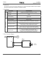
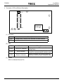
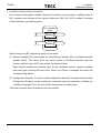
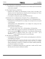
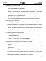
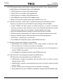
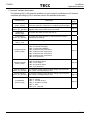
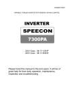
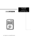
7300PA
LonWorks
Application Manual
TECO Frequency Inverter
7300PA LonWorks
Communication Interface
Application Manual
Version: 01
7300PA
LonWorks
Application Manual
Table of Content
1 Introduction............................................................................................................................ 2
2 Specification .......................................................................................................................... 2
3 Wire Connection Diagram ..................................................................................................... 2
4 Terminals, LED and Button Description .............................................................................. 3
5 Installation Method ................................................................................................................ 4
6 Inverter Setting ...................................................................................................................... 4
1. Set Method ......................................................................................................................... 4
2. Inverter Communication Status ....................................................................................... 4
7 Lonworks Communication illustration................................................................................. 5
8 VSD illustration ...................................................................................................................... 6
1. Configuration Property Description................................................................................. 8
2. Network Variable Description ......................................................................................... 13
1/18
7300PA
LonWorks
Application Manual
1 Introduction
The manual covers communication between PA-L interface card and 7300PA inverter installed
with such card with other modules in LonWorks network.
2 Specification
Communicatio
n Specification
Part Number
4H300D5960002
Transceiver
Echelon free topology transceiver (FTT-10A).
Baud Rate
78 kps
Connect Medium
Twisted wire
Communication Status
3 LED indicators
Product Features
Outline Dimension
63mm x 86mm
Network Variables and
Configuration Properties
Controlling Functions
Monitoring Function
20 Network Variables and 26 Configuration Properties
Inverter RUN/STOP, Forward/Reverse RUN. Frequency Command,
External Fault, Fault Reset. 4 Multi-Function Commands.
All the Output of Analog, Digital Output Terminal.
Inverter status, Fault Content, Output Frequency, Voltage, Current
and DC voltage. All Outputs of Digital Output Terminal.
All Inputs of the Analog, Digital terminal, PID Feedback Value.
AUX Function Setting, PID Gain, 3 Jump Frequency,
2 Group Acceleration and Deceleration Time,
Stall prevention Level during Running and Acceleration.
Number of Auto Restart Attempt. Energy saving.
Setting Function
3 Wire Connection Diagram
7300 PA
IM
PA-L
2CN
CN1
TB1
To Lon
Networks
2/18
7300PA
LonWorks
Application Manual
4 Terminals, LED and Button Description
LED1
SW1
ECHELON
FTT-10A
CN1
LED2 LED3
TB1
(1) Terminals
Description
CN1
Connect with 7300PA 2CN terminal on control board
TB1
Lon Network terminal
(2) LED
LED
Function
Description
LED1
SERVICE Indicator
LED2
Send Indicator
Blinking indicates sending the data of
inverter to communication interface card.
LED3
Receive Indicator
Blinking indicates the inverter receiving
data from communication interface card.
Blinking indicates PA-L card without
configuration.
(3) Button
SW1: LonWorks Service Pin
3/18
7300PA
LonWorks
Application Manual
5 Installation Method
(1) Cut off inverter power supply
(2) Plug two inside isolation pins
in holes on 7300PA control
board.
(3) Set up PA-L interface card on
the control board. The two
installation holes should be
right to isolation pins, CN1 to
2CN of the control board.
(4) Connect the LonWorks net
wire to terminal TB1 on PA-L
interface card.
PA-L CN1
Control Board 2CN
Isolation Pin
Control Board
6 Inverter Setting
1. Set method
(1) Start inverter 7300PA, and switch to PRGM mode, then set the following parameters.
Sn-08 = 1100 (Frequency and RUN/STOP command provided by RS-485,
continuously running in communication error.)
Sn-23 = 1
(Inverter Address: 1)
Sn-24 = 1100 (Baud Rate 19200 BPS, without parity check)
Cn-31 = 01.0 s (communication checkout time: 1s)
Restarting power supply after setting the parameters ensures normally communication
between Inverter 7300PA and PA-L interface card .
(2) In stop mode, switch inverter 7300PA to PRGM mode and set the following parameters.
Sn-02 = 4
(V/f pattern set by parameter)
Cn-03 = Cn-01 set value
It is also available for setting parameters provided by PA-L using Config. software now.
(3) Then, switching 7300PA inverter to DRIVE mode, It is available for controlling the
inverter 7300PA by LonWorks network.
2. Inverter Communication Status
If there is error in communication between PA-L inverter card and 7300PA, the digital
operator will show the warning message. Follow is the description:
(1) The digital operator will blink 'RS-485 comm Ready' or 'CALL' while receiving no data in
1s after inverter start. Such message will disappear in receiving data.
(2) The digital operator will display warning 'RS-485 comm Fault 1' or 'CPF21' if receiving
no data in 1s after communication succeed.
(3) If the baud rate, data bits, stop bit or parity of data received by the inverter is not correct,
the digital operator will blink 'RS-485 comm Fault 2' or 'CPF22'.
4/18
7300PA
LonWorks
Application Manual
7 LonWorks Communication Illustration
PA-L interface card applies LonMark object and LonWorks communication. LonMark object of
PA-L interface card consists of two objects: Node and VSD (S/N: 6010 LonMark Functional
Profile Definition), as following figure:
PA-L Interface
Card
Node
Object
VSD
Object
Data of node and VSD objectors divided into two sorts:
(1) Network Variable (NV): also divided into Input Network Variable (NVI) and Output Network
Variable (NVO). The former (NVI) can control status of LonWorks interface card and
inverter, while the later (NVO) can monitor the status of them.
Each network variable has individual type. On the LonWorks network, network variables
with same type can bind with each other. When one of them is changed, the others will
correspondingly adjust.
(2) Configuration Property: to control inverter configuration and save the parameters and data.
Configuration Property can be modified by LonWorks network configuration software (as
LonMaker Integration Tool, etc) only. Other devices can not modify them.
VSD object content will be illustrated in the next section.
5/18
7300PA
LonWorks
Application Manual
8 VSD Illustration
VSD object provides 20 network variables (6 input network variables and 14 output network
variables) and 26 configuration properties. The function of VSD object is briefly described:
Variable Speed Motor Drive Object (1)
nviDrvSpeedStpt
SNVT_switch
nviDrvSpeedScale
SNVT_lev_percent
LonMark Mandatory
Network Variables
LonMark Optional
Network Variables
nvoDrvSpeed
SNVT_lev_percent
nvoDrvCurnt
SNVT_amp
nvoDrvVolt
SNVT_volt
LonMark Mandatory
Configuration Properties
nciNmlSpeed
nciMinSpeed
nciRampUpTm
nciSndHrtBt
nciNmlFreq
nciMaxSpeed
nciRampDownTm
LonMark Optional
Configuration Properties
nciRcvHrtBt
nciLocation
nciMinOutTm
nciDrvSpeedScale
nviOpCommands
SNVT_state
nviDoCommands
SNVT_state
7300PA
Network Variables
nvoOpStatus
SNVT_state
nvoOpStatus2
SNVT_state
Continued on the next page
6/18
7300PA
LonWorks
Application Manual
Continued from the previous
page
nviAo1Command
SNVT_lev_percent
nvoDrvFreqHz
SNVT_freq_hz
nviAo2Command
SNVT_lev_percent
nvoDcVolt
SNVT_volt
nvoFault
SNVT_state
nvoAi1Value
SNVT_lev_percent
7300PA
Network Variables
nvoAi2Value
SNVT_lev_percent
nvoDiStatus
SNVT_state
nvoDoStatus
SNVT_state
nvoPIDCommand
SNVT_lev_percent
nvoPIDFeedback
SNVT_lev_percent
7300PA
Configuration Properties
nciEnergySave
nciPID_Pgain
nciPID_Dtime
nciProFreq1
nciProFreq3
nciAutoRstart
nciStallLevRun
nciRampDownTm2
nciAuxSel
nciPID_Itime
nciFeedBackScl
nciProFreq2
nciProFreqBW
nciStallLevAcc
nciRampUpTm2
7/18
7300PA
LonWorks
Application Manual
1. Configuration Property Description
The following are the configuration properties provided by PA-L interface card. The property
type will be listed below the parameter name. If the type begins with SNVT, such property
can be used as network variable.
Some of the configuration property has the one corresponding to inverter 7300PA. Such
property has two adjusting methods.
Refresh Method
Inverter Parameter
LonWorks Network Data
Adjusting via LonWorks Network
Refreshed right away
Refreshed right away
Adjusting via inverter operation panel
Refreshed right away
Refreshed in the next start.
The parameters Cn, Sn in inverter 7300PA only can be modified in PRGM mode. If the
configuration property corresponding to parameter Cn, Sn is required modifying, such
action should be done after switching to PRGM mode when the inverter is in stop mode.
Parameter Name
Description
Range
7300PA Refer to
page
Parameter
nciNmlSpeed
(SCPTnomRPM)
Configure rated speed of the motor with
default 1800 RPM.
0 - 65535RPM
nciNmlFreq
(SCPTnomFreq)
Configure rated frequency of the motor
with default 60.0Hz.
0 - 100.0Hz
Cn-02*1 Page 10
0 - 40.000%
Cn-15*1
-
100.000 - 109.000%
Cn-14*1
-
0.0 - 6000.0 sec
Bn-01
Page 10
0.0 - 6000.0 sec
Bn-02
Page 10
0.0 - 6553.4 sec
-
Page 10
Configure max receive time of
nviDrvSpeedStpt, nviDrvSpeedScale.
(SCPTmaxRcvTime)
Default 0 s.
0.0 - 6553.4 sec
-
Page 11
Configure min send time of nvoDrvCurnt,
nvoDrvSpeed, and nvoDrvVolt.
(SCPTminSendTime)
Default 0.5 s.
0.0 - 6553.4 sec
-
Page 11
String length:
31 characters.
-
-
-163.84% - 163.83%
-
-
nciMinSpeed
Configure lower frequency limit on
(SCPTminSetPoint) percentage of rated frequency.
nciMaxSpeed
Configure upper frequency limit on
(SCPTmaxSetPoint) percentage of rated frequency.
nciRampUpTm
Configure acceleration time of the motor.
(SCPTrampUpTm)
nciRampDownTm
(SCPTrampDownTm)
nciSndHrtBt
Configure deceleration time of the motor.
Configure max send time of nvoDrvCurnt,
(SCPTmaxSendTime) nvoDrvSpeed and nvoDrvVolt. Default 0 s.
nciRcvHrtBt
nciMinOutTm
nciLocation
(SCPTlocation)
Label the location of the motor or inverter.
nciDrvSpeedScale Configure nviDrvSpeedScale default
(SCPTdefScale) value.
-
Page 10
8/18
7300PA
LonWorks
Application Manual
Parameter Name
Description
Range
7300PA Refer to
Page
Parameter
nciEnergySave
(SNVT_switch)
Configure energy-saving available or
unavailable.
0-1
Sn-09
nciAuxSel
(SNVT_count)
Configure the functions of analog input
terminal Aux.
0 - 11
Sn-19
0.01 - 10.00
Bn-14
Page 12
0.0 - 100.0 sec
Bn-15
Page 12
nciPID_Dtime
Configure differential time of PID function.
(SNVT_time_sec)
0.0 - 1.0 sec
Bn-16
Page 12
nciFeedBackScl
Configure PID feedback value gain.
(SNVT_multiplier)
0.01 - 10.00
Bn-13
Page 12
nciPID_Pgain
Configure proportion gain of PID function.
(SNVT_multiplier)
nciPID_Itime
Configure integrate time of PID function.
(SNVT_time_sec)
*1
*1
Page 11
Page 11
nciProFreq1
(SNVT_freq_hz)
Configure prohibit frequency 1.
0.0 - 180.0 Hz
Cn-16*1 Page 12
nciProFreq2
(SNVT_freq_hz)
Configure prohibit frequency 2.
0.0 - 180.0 Hz
Cn-17*1 Page 12
nciProFreq3
(SNVT_freq_hz)
Configure prohibit frequency 3.
0.0 - 180.0 Hz
Cn-18*1 Page 12
nciProFreqBW
(SNVT_freq_hz)
Configure range of prohibit frequency.
0.0 - 25.5 Hz
Cn-19*1 Page 12
0 - 10
Cn-36*1 Page 12
Configure acceleration stall prevention
level.
30 - 170 (%)
Cn-28*1 Page 12
Configure running stall prevention level.
30 - 170 (%)
Cn-30*1 Page 12
nciAutoRstart
(SNVT_count)
nciStallLevAcc
(SNVT_count)
nciStallLevRun
(SNVT_count)
Configure number of auto restart attempt.
nciRampUpTm2
Configure 2nd acceleration time.
(SNVT_time_sec)
0.0 - 6000.0 sec
Bn-03
Page 10
nciRampDownTm2
Configure 2nd deceleration time.
(SNVT_time_sec)
0.0 - 6000.0 sec
Bn-04
Page 10
*1. These parameters only can be modified after switching to Program mode.
9/18
7300PA
LonWorks
Application Manual
(1) Motor Rated Speed (nciNmlSpeed)
• nciNmlSpeed can configure the rated speed of motor. Please input the relevant data
on the motor nameplate.
(2) Motor Rated Frequency (nciNmlFreq)
• nciNmlFreq can configure the rated frequency of motor, which is the base of the
frequency command, output frequency, frequency lower limit and upper limit. Please
input the data comply with the motor nameplate.
• It is available for setting this property under PRGM mode only.
(3)Acceleration Time 1(nciRampUpTm), Deceleration Time 1 (nciRampDownTm),
Acceleration Time 2 (nciRampUpTm2) and Deceleration Time 2 (nciRampDownTm2)
• nciRampUpTm and nciRampUpTm2 can configure the running time from zero speed
to nominal speed.
nciRampUpDown and nciRampUpDown 2 can configure the running time from
nominal speed to zero speed.
Actual accelerate/ decelerate time is:
SET value of accel./ decel. time × nviDrvSpeedStpt x nviDrvSpeedScale
• Inverter 7300PA has two groups of acceleration and deceleration time. The multifunction input terminals
5
- 8 and multi-function 1-4 providing by nviOpCommands
are both available for switching. Please refer to page 16 or Sn-15 ~ Sn-18
description in 'Inverter 7300PA user manual' for more information.
(4) Max Send Time (nciSndHrtBt)
• nciSndHrtBt sets Max send time of PA-L interface card sending data of nvoDrvCurnt,
nvoDrvSpeed and nvoDrvVolt.
• If network variables in PA-L are bound with other network variables, PA-L interface
card will inform the later to modify automatically as long as the former is modified.
Setting nciSndHrtBt can compel Pa-L interface send network variables periodically,
even the said variables is not modified.
• Setting 0 to nciSndHrtBt indicates that max. send time is invalid, and PA-L sends
data only when the network variables are modified.
10/18
7300PA
LonWorks
Application Manual
(5) Max Receive Time (nciRcvHrtBt)
• nciRcvHrtBt sets Max receive time of PA-L interface card receiving data of
nviDrvSpeedStpt and nviDrvSpeedScale.
• If the said variables have still not been refreshed by other module in the LonWorks
network in the specified time, the interface card will change them to default value
and pause the communication with the inverter. If there is any module sending
operation and frequency command periodically, such function will monitor the
communication error of LonWorks network.
• Setting 0 to nciSndHrtBt indicates that max receive time is invalid. The inverter will
run at the default speed as long as LonWorks network fault on communication.
(6) Min Send Time (nciMinOutTm)
• nciMinOutTm sets Min send time of PA-L interface card sending data of nvoDrvCurnt,
nvoDrvSpeed and nvoDrvVolt.
• If network variables in PA-L are bounded with other network variables, PA-L interface
card will inform the later to modify automatically as long as the former is modified.
Setting nciSndHrtBt can avoid certain network variables densely sending to
influence the performance of LonWorks network.
• Setting 0 to nciMinOutTm indicates that min send time is invalid.
(7) Energy-saving Selection (nciEnergySave)
• nciEnergySave divides into 'State' and 'Value', while can configure the energy saving
function is available or not.
State = 0 or Value = 0%, such function is unavailable.
State = 1 or Value = 100%, such function is available.
• It is available for setting this property under PRGM mode only.
(8) Multi-function Analog Input Terminal Aux Selection (nciAuxSel)
• nciAuxSel can configure the inverter multi-function analog input terminal Aux
function.
• If nciAuxSel is set to 9, which starts PID function, terminal Vin or Ain are set as PID
feedback value.
• For more information on multi-function terminal Aux function, please refer to Sn-19
description in Inverter 7300PA user manual.
• For more information on PID function, please refer to PID function in Inverter 7300PA
user manual.
• It is available for setting this property under PRGM mode only.
11/18
7300PA
LonWorks
Application Manual
(9) PID Proportion Gain (nciPID_Pgain), Integrate Time (nciPID_ITime), Differential Time
(nciPID_Dtime) and Feedback Scale (nciFeedBackScl)
• nciPID_Pgain can configure PID proportion gain.
• nciPID_ITime can configure PID integrate time.
• nciPID_Dtime can configure PID differential time.
• nciFeedBackScl can configure PID feedback scale.
• Before executing PID, please ensure that nciAuxSel is set to 9.
(10) Prohibit Frequency1 (nciProFreq1), Prohibit Frequency2 (nciProFreq2), Prohibit
Frequency3 (nciProFreq3) and Prohibit Frequency Range (nciProFreqBW)
• Inverter 7300PA has three groups of prohibit frequency to prevent mechanical
resonance frequency. After setting, the motor will accelerate/ decelerate in prohibit
range frequency range, but not running in constant speed in the range.
• Any of the prohibit frequency setting to 0 means such function is invalid.
• Prohibit frequency range setting to 0 means all the prohibit frequencies are invalid.
• Setting of prohibit frequency should comply with the following regulation:
nciProFreq1 > nciProFreq2 > nciProFreq3
• It is available for setting this property under PRGM mode only.
(11) Number of Auto Restart Attempt (nciAutoRstart)
• nciAutoRstart can configure number of auto restart attempt in particular faults.
Such number set to 0 means auto-restart is unavailable.
• For more information on auto restart function, please refer to Cn-36 description in
Inverter 7300PA user manual.
• It is available for setting this property under PRGM mode only.
(12) Stall Prevention Level during Acceleration (nciStallLevAcc),
Stall Prevention Level during Running (nciStallLevRun)
• nciStallLevAcc configure acceleration stall prevention level of Inverter (inverter
nominal current: 100%).
• nciStallLevRun configure running stall prevention level of Inverter (inverter nominal
current: 100%).
• Inverter nominal current is based on the one labeled on nameplate.
• Such parameter of Inverter 7300PA is available for setting under PROGRAM mode.
12/18
7300PA
LonWorks
Application Manual
2. Network Variable Description
The following list on 20 network variables (6 input network variables and 14 network
variables) providing by PA-L interface card is the detailed description.
Variable Name
nviDrvSpeedStpt
(SNVT_switch)
nviDrvSpeedScale
(SNVT_lev_percent)
nvoDrvCurnt
(SNVT_amp)
nvoDrvSpeed
(SNVT_lev_percent)
nvoDrvVolt
(SNVT_volt)
Description
Refer to
page
To control run, stop and provide low-resolution frequency
Page 15
command (frequency command is in nciNmlFreq percentage).
To control (nviDrvSpeedStpt) fine scale of frequency command.
Negative value is the reverse running command.
To monitor the output current. Unit is 0.1A.
To monitor the output frequency. Output frequency show in
nciNmlFreq percentage.
To monitor output voltage. Unit is 1V.
Page 16
-
nviOpCommands
(SNVT_state)
To control following command:
• BIT 0: External Fault (EB).
• BIT 1: Fault Clear (RESET).
• BIT 2: Multi-function command 1.
• BIT 3: Multi-function command 2.
• BIT 4: Multi-function command 3.
• BIT 5: Multi-function command 4.
• BIT 6-15: Reserved.
Page 16
nviDoCommands
(SNVT_state)
To control output of multi-function output terminals.
• BIT 0: R2A-R2C output.
• BIT 1: DO1 output.
• BIT 2: R1A-R1C output.
• BIT 3-15: Reserved
Page 16
nviAo1Command
(SNVT_lev_percent)
To control the output of multi-function analog output terminal
AO1. 100% is corresponding to 10V.
Page 17
nviAo2Command
(SNVT_lev_percent)
To control the output of multi-function analog output terminal
AO2. 100% is corresponding to 10V.
Page 17
To monitor the inverter status:
• BIT 0 : running
• BIT 1 : reverse running
• BIT 2 : operation is ready
• BIT 3 : fault
• BIT 4-15 : reserved
Page 18
nvoOpStatus
(SNVT_state)
13/18
7300PA
LonWorks
Application Manual
Variable Name
Description
Refer to
Page
nvoOpStatus2
(SNVT_state)
To monitor the inverter status.
• BIT 0 : Running
• BIT 1 : Zero speed
• BIT 2 : Frequency Agree
• BIT 3 : Setting Frequency Agree
• BIT 4 : Frequency Detection 1
• BIT 5 : Frequency Detection 2
• BIT 6 : Reserved
• BIT 7 : Under Voltage detection
• BIT 8 : Inverter no output
• BIT 9-10 : Reserved
• BIT 11 : Over Torque detection
• BIT 12 : Frequency command loss
• BIT 13-15 : Reserved
Page 18
nvoDrvFreqHz
(SNVT_freq_hz)
nvoDcVolt
(SNVT_volt)
To monitor output frequency, unit is 0.1Hz.
To monitor DC voltage, unit is 1V.
-
To monitor present fault content.
• BIT 0 : Over Current (OC) or ground fault (GF)
• BIT 1 : Over Voltage (OV)
• BIT 2 : Inverter Over Load (OL1, OL2)
• BIT 3 : Inverter Over Heat (OH)
• BIT 4 : Reserved
• BIT 5 : Reserved
• BIT 6 : Reserved
• BIT 7 : External Fault (EFxx)
• BIT 8 : Control Loop Fault (CPFxx)
• BIT 9 : Motor Over Load (OL3)
• BIT 10 : Reserved
• BIT 11 : Reserved
• BIT 12 : Under voltage or MC Damage (UVx)
• BIT 13-15:Reserved
Page 17
nvoAi1Value
(SNVT_lev_percent)
To monitor multi-function terminal VIN+AIN input, in
percentage.
Page 18
nvoAi2Value
(SNVT_lev_percent)
To monitor multi-function terminal AUX input, 100% to input
10V.
nvoFault
(SNVT_state)
-
14/18
7300PA
LonWorks
Application Manual
Variable Name
Description
nvoDiStatus
(SNVT_state)
To monitor multi-function digital input terminal status:
• BIT 0 : Terminal 1 close
• BIT 1 : Terminal 2 close
• BIT 2 : Terminal 3 close
• BIT 3 : Terminal 4 close
• BIT 4 : Terminal 5 close
• BIT 5 : Terminal 6 close
• BIT 6 : Terminal 7 close
• BIT 7 : Terminal 8 close
• BIT 8-15 : Reserved
nvoDoStatus
(SNVT_state)
To monitor multi-function output terminal status:
• BIT 0 : Multi-function terminal R2A-R2C output
• BIT 1 : Multi-function terminal DO1 output
• BIT 2 : Multi-function terminal R1A-R1C output
• BIT 8-15 : Reserved
nvoPIDCommand
(SNVT_lev_percent)
Reserved
nvoPIDFeedback
(SNVT_lev_percent)
To monitor input of PID feedback value, shown in percentage.
0 means PID does not start.
Refer to
Page
-
Page 17
-
(1) RUN/STOP Command (nviDrvSpeedStpt.State)
• nviDrvSpeedStpt divides into 'State' and 'Value' to control RUN/STOP command and
frequency command.
• nviDrvSpeedStpt.State content:
nviDrvSpeedStpt.State = 0 :
STOP command
nviDrvSpeedStpt.State = 1 :
RUN command
nviDrvSpeedStpt.State = -1 : command idle (default)
• Under following circumstances, such variable will be default value.
• After power on the machine and before reading the network variable.
• No nviDrvSpeedStpt or nviDrvSpeedStpt commands received during the min.
receiving time (nciRcvHrtBt).
(2) Frequency Command (nviDrvSpeedStpt.Value)
• nviDrvSpeedStpt.Value and nviDrvSpeedScale control the frequency command. The
actual frequency command is as following:
Command = nclNmlFreq x nviDrvSpeedStpt.Value x nviDrvSpeedScale
• the 1 unit of nviDrvSpeedStpt.value shows 0.5%, which range from 0%~100%.
Thusly, 0 means to 0%, 200(and above 200) means 100%.
15/18
7300PA
LonWorks
Application Manual
(3) Frequency Command Scale and Forward/ Reverse RUN (nviDrvSpeedScale)
• nviDrvSpeedScale range from -163.84% to 163.84%. Positive value represents
forward running command while negative value reverse command.
• Default value of nviDrvSpeedScale is determined by nciDrvSpeedScale.
• Here is an illustration on the relationship between frequency command said variable
and actual frequency command.
nciNmlFreq
nviDrvSpeedStpt.Value
nviDrvSpeedScale Actual Frequency
60Hz
100%
100%
Forward Run 60Hz
60Hz
80%
-75%
Forward Run 36Hz
50Hz
80%
-100%
Reverse Run 40Hz
(4) Inverter Operation Command (nviOpCommands)
• nviOpCommands can configure inverter external fault, fault clear (reset) and multifunction command. Description is as following:
Bit
Function
0
Set external fault.
Malfunction terminals R3A-R3C close as there is no output in inverter.
1
Fault clear (RESET), It can clear fault while nviDrvSpeedStpt.State = 0.
2
Multi-function command 1
(Actual function is determined by Sn-15, default is Multi-step speed 1).
3
Multi-function command 2
(Actual function is determined by Sn-16, default is Multi-step speed 2).
4
Multi-function command 3
(Actual function is determined by Sn-17, default is JOG command).
5
Multi-function command 4
(Actual function is determined by Sn-18, default is external fault).
6-15
Reserved
(5) Multi-function Terminal Output (nviDoCommands)
• nviDoCommands matching with 7300PA parameters setting can configure the output
of multi-function terminal DO1, R1A-R1C and R2A-R2C.
Bit
Function
0
Set R2A-R2C action. (It is available while Sn-20=0F only.)
1
Set DO1 action. (It is available while Sn-21=0F only.)
2
Set R1A-R1C action. (It is available while Sn-22=0F only.)
3-15
Reserved
16/18
7300PA
LonWorks
Application Manual
(6) Multi-function Analog Terminal Output (nviAo1Command, nviAo2Command)
• When Sn-26=0A, nviAo1Command is available for setting inverter analog input
terminal Ao1.
100% compares to Ao1 output 10V.
• When Sn-27=0A, nviAo2Command is available for setting inverter analog input
terminal Ao2.
100% compares to Ao2 output 10V.
(7) Inverter Fault Status (nvoFault)
• nvoFault can monitor the inverter fault status.
Bit
Function
0
Over current (OC) or ground fault (GF)
1
Over voltage (OV)
2
Inverter over load (OL1, OL2)
3
Inverter over heat (OH)
4-6
Reserved
7
External Fault (EF3, EF5, EF6, EF7, EF8)
8
Control loop exception (CPF02), EEPROM exception (CPF03),
EEPROM code exception (CPF04) or A/D exception (CPF05).
9
Motor over load (OL3)
10-11
12
13-15
Reserved
Under voltage or instantaneous stop protection (UV1), control loop voltage over
lower (UV2) or MC fault (UV3)
Reserved
(8) Inverter Multi-function Output Terminals Monitor (nvoDoStatus)
• The following is the nvoDoStatus bit and content description:
Bit
Function
0
Multi-function terminal R2A-R2C output.
(Comply with Sn-20. Factory set: running)
1
Multi-function terminal DO1 output.
(Comply with Sn-21. Factory set : zero Speed)
2
Multi-function terminal R1A-R1C output.
(Comply with Sn-22. Factory set : frequency agree)
3-15
Reserved
17/18
7300PA
LonWorks
Application Manual
(9) Inverter Status Monitor (nvoOpStatus, nvoOpStatus2)
• The following is the nvoOpStatus bit and content description:
Bit
Function
0
1: Running
1
1: Reverse, 0: Forward
2
1: Inverter is ready to operate. (DRIVE mode with no alarm, fault)
3
1: Exception but not CPF00, CPF01.
4-15
Reserved
• The following is the nvoOpStatus2 bit and content description:
Bit
Function
0
1 : Running
1
1 : Zero Speed
1 : Frequency Agree
2
3
4
(
Frequency Command -
Cn-22
)
< Output frequency <
(
Frequency Command +
Cn-22
)
1 : Frequency Agree and (Cn-21 - Cn-22) < output frequency < (Cn-21 + Cn-22)
1 : Frequency detection 1
Cn-22
(Refer to right figure )
Cn-21
F out
5
1 : Frequency detection 2
(Refer to right figure)
6
Reserved
7
1 : Under voltage detection
8
1 : Inverter has no output.
9-10
F detection 1
1
0
1
F detection 2
0
1
0
Reserved
11
1 : Over torque detection (Detection Level : Cn-26, Detection Time : Cn-27)
12
1 : Frequency command loss.
13-15
Reserved
(10) Inverter Analog Input Monitor (nvoAi1Value)
• Monitor input of Multi-function analog terminal VIN, AIN, with range 0-100%.
• nvoAi1Value 0-100% compares to VIN input 0-10V, or AIN input 4-20mA. If both VIN,
AIN are input, the inputs of VIN, AIN will be added before transferring to percentage.
18/18