1
engineering
mannesmann
Rexroth
TRANS 01-D Version 5VRS
Motion and Logic Control System
for Indramat DIAX02 Drives
Reference Manual
DOK-CONTRL-TRANS01D*RM-ANW2-AE-P
274706
Indramat
TRANS 01-D
Title
Kind of documentation
Docu-type
TRANS 01-D Motion and Logic Control System
Reference Manual
DOK-CONTRL-TRANS01D*RM-ANW2-AE-E1,44
Internal filing remarks
Purpose of this document
Course of modifications
To familiarize the reader with the configuration and operation of the
TRANS 01-D
Revision
Date
Remarks
A
4/97
Initial Release
B
1/98
Changes to:
Section 3 (Programming)
Section 4 (Parameters)
Section 5 (I/O Functional Description)
Section 6 (Diagnostics and Monitoring)
Added:
Appendices A - D
Copyright
INDRAMAT GmbH, 1998
Copying this document, and giving it to others and the use or communication
of the contents thereof without express authority, are forbidden. Offenders are
liable for the payment of damages. All rights are reserved in the event of the
grant of a patent or the registration of a utility model or design (DIN 34-1).
Validity
Published by
All rights are reserved with respect to the content of this documentation and
the availability of the product.
The Rexroth Corporation • Indramat Division
5150 Prairie Stone Parkway • Hoffman Estates, Illinois • 60192
Ph. (847) 645-3600 • Fax (847) 645-6201
ii About this documentation
DOK-CONTRL-TRANS01D*RM-ANW2-AE-E1,44
TRANS 01-D
Contents
1 Introduction
1-1
1.1 TRANS 01-D Control..................................................................................................................................1-1
1.2 Technical Specifications.............................................................................................................................1-1
1.3 Purpose of Manual .....................................................................................................................................1-2
2 CTA 10-1 Operation
2-1
2.1 Performing Tasks with the CTA 10-1 .........................................................................................................2-1
2.2 Display and Keypad Overview....................................................................................................................2-1
3 Programming
3-1
3.1 Enabling Program Changes .......................................................................................................................3-1
3.2 Programming Capability Description ..........................................................................................................3-2
3.3 Application Programming Requirements....................................................................................................3-3
Start of the Program ............................................................................................................................3-3
End of the Program .............................................................................................................................3-3
Axis Enable and Disable (G20, G21)...................................................................................................3-4
Basic Homing Program .......................................................................................................................3-5
Homing and Zero Offset (NC Code G74 & G69).................................................................................3-6
Positioning (NC Code G00, G01, G90 & G91) ..................................................................................3-10
With / Without Lag During Positioning (G61 & G62) .........................................................................3-10
Enable/Disable Feed To A Positive Stop (G75 & G76) .....................................................................3-11
Adaptive Depth Control (G08) ...........................................................................................................3-12
External Feedback Devices - Distance Coded Linear Scale.............................................................3-16
Rotary Motion Control........................................................................................................................3-18
Feedrate (NC Code F).......................................................................................................................3-22
Dwell (NC Code G04)........................................................................................................................3-22
Tool Corrections (NC Code T)...........................................................................................................3-22
Spindle Speed Control (NC Code S) .................................................................................................3-27
Spindle Positioning Control (NC Code P) ..........................................................................................3-27
Auxiliary Functions (NC Code M) ......................................................................................................3-29
Program Jumps .................................................................................................................................3-29
3.4 Programming Examples...........................................................................................................................3-35
Display Program Blocks ....................................................................................................................3-35
Program Entry Mode .........................................................................................................................3-36
Positioning .........................................................................................................................................3-38
Dwell Time.........................................................................................................................................3-44
DOK-CONTRL-TRANS01D*RM-ANW2-AE-E1,44
Contents I
TRANS 01-D
Auxiliary Functions.............................................................................................................................3-46
Home Axis .........................................................................................................................................3-48
4 Parameters
4-5
4.1 Introduction.................................................................................................................................................4-5
CTA 10-1 .............................................................................................................................................4-5
Visual TRANS......................................................................................................................................4-6
Serial Communications........................................................................................................................4-6
4.2 Process Parameters...................................................................................................................................4-8
P00 TRANS 01-D Number .................................................................................................................4-8
P01 Trans Group Number ..................................................................................................................4-9
P02 Axis Configuration .....................................................................................................................4-10
P03 Auxiliary Outputs at Emergency Stop........................................................................................4-12
P04 Auxiliary Outputs at Immediate Stop.........................................................................................4-13
P05 Automatic/Manual Switching .....................................................................................................4-14
P06 System Options.........................................................................................................................4-15
P07 Language ..................................................................................................................................4-16
P08 Maximum Path Speed...............................................................................................................4-17
P09 Maximum Path Acceleration .....................................................................................................4-18
P10 Process Position Units ..............................................................................................................4-19
4.3 Axis Parameters .......................................................................................................................................4-20
Aa00 Parameter Set .........................................................................................................................4-20
Aa01 Special Functions - Feed to Positive Stop ..............................................................................4-21
Aa01 Special Functions - Adaptive Depth ........................................................................................4-22
Aa01 Special Functions - Home Switch Monitoring..........................................................................4-23
Aa02 Units ........................................................................................................................................4-25
Aa03 Feed Constant.........................................................................................................................4-27
Aa04 Positioning Feedback Type - Motor Encoder ..........................................................................4-28
Aa04 Positioning Feedback Type - Linear Scale..............................................................................4-29
Aa04 Positioning Feedback Type - External Rotary Encoder ..........................................................4-30
Aa04 Positioning Feedback Type - External Rotary Absolute Encoder ...........................................4-31
Aa05 Gear Ratio...............................................................................................................................4-32
Aa06 Overtravel Limits .....................................................................................................................4-33
Aa07 Bipolar Torque Limit ................................................................................................................4-34
Aa08 Axis Gains ...............................................................................................................................4-35
Aa09 Ramp.......................................................................................................................................4-36
Aa10 Speeds ....................................................................................................................................4-37
Aa11 Directions ................................................................................................................................4-38
Aa12 Homing Reference ..................................................................................................................4-39
Aa13 Reference Position..................................................................................................................4-40
Aa14 Overload Factor ......................................................................................................................4-41
Aa15 Maximum Tool Correction.......................................................................................................4-42
Aa16 Axis AF Switching....................................................................................................................4-43
Aa17 Control Windows .....................................................................................................................4-44
II
Contents
DOK-CONTRL-TRANS01D*RM-ANW2-AE-E1,44
TRANS 01-D
Aa18 External Encoder Control Window .......................................................................................... 4-45
Aa19 Deactivate Absolute Encoder Function ...................................................................................4-46
Aa20 Maximum Speed to Positive Stop ........................................................................................... 4-47
Aa21 Positive Stop Torque %...........................................................................................................4-48
Aa22 Home to Stop Distance ...........................................................................................................4-49
Aa30 Maximum Speed for Adaptive Depth ......................................................................................4-50
Aa31 Linear Encoder: Pre-Limit .......................................................................................................4-51
Aa32 Linear Encoder: Maximum Deflection .....................................................................................4-52
Aa33 Linear Encoder Resolution......................................................................................................4-53
Aa34 Linear Encoder Direction.........................................................................................................4-54
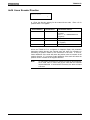
4.4 Spindle Parameters..................................................................................................................................4-55
User Selectable Parameter (P, Q, R and S) Sets .............................................................................4-55
General Parameter and Motor Parameter Sets.................................................................................4-55
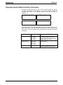
Displaying Spindle Motor/Controller Information ...............................................................................4-56
SP1 Positioning Speeds ...................................................................................................................4-57
SP2 Control Windows.......................................................................................................................4-58
SP3 KV Factor..................................................................................................................................4-59
SP4 Bi-polar Velocity Limit ...............................................................................................................4-60
SP5 Gear Ratio ................................................................................................................................4-61
SP6 Thresholds ................................................................................................................................4-62
SP7 Ramp - RPM1 ...........................................................................................................................4-63
SP8 Ramp - RPM2 ...........................................................................................................................4-64
SP9 Ramp 3 .....................................................................................................................................4-65
SP10 Gain 1 .....................................................................................................................................4-66
SP11 Gain 2 .....................................................................................................................................4-67
SP12 Gain RPM ...............................................................................................................................4-68
SP13 POS-Gain ...............................................................................................................................4-69
SP14 PQ-Functions..........................................................................................................................4-70
SA1 Maximum Speeds .....................................................................................................................4-73
SA2 Zero Velocity Window ...............................................................................................................4-74
SA3 Velocity Window .......................................................................................................................4-75
SA4 Bipolar Torque Limit..................................................................................................................4-76
SA5 Motor Overtemperature Warning..............................................................................................4-77
SA6 Motor Overtemperature Shutdown ...........................................................................................4-78
SA7 Directions..................................................................................................................................4-79
SA8 Resolution of External Feedback..............................................................................................4-80
SA9 Reference Offsets.....................................................................................................................4-81
SA10 Motor Oscillation Settings .......................................................................................................4-82
SA11 Function 1 ...............................................................................................................................4-83
SA12 Function 2 ...............................................................................................................................4-85
SM1 Feedback .................................................................................................................................4-87
SM2 Poles / Slip Limit.......................................................................................................................4-88
SM3 Flux / Current ...........................................................................................................................4-89
SM4 Sign ..........................................................................................................................................4-90
DOK-CONTRL-TRANS01D*RM-ANW2-AE-E1,44
Contents III
TRANS 01-D
SM5 Motor Functions .......................................................................................................................4-91
SM10 Feedback ...............................................................................................................................4-92
SM11 Poles / Slip Limit.....................................................................................................................4-93
SM12 Flux / Current .........................................................................................................................4-94
SM13 Sign ........................................................................................................................................4-95
SM14 Motor Functions .....................................................................................................................4-96
5 I/O Functional Description
5-1
5.1 Introduction.................................................................................................................................................5-1
5.2 I/O Hardware Configuration and Reconfiguration ......................................................................................5-2
5.3 Enables.......................................................................................................................................................5-3
Enable..................................................................................................................................................5-3
Enable-Forward ...................................................................................................................................5-3
5.4 Operator Interface ......................................................................................................................................5-4
Automatic/Manual................................................................................................................................5-4
Forward ...............................................................................................................................................5-5
Reverse ...............................................................................................................................................5-5
Toolchange..........................................................................................................................................5-6
Fault Clear ...........................................................................................................................................5-6
5.5 Cycle Interface............................................................................................................................................5-7
Inputs...................................................................................................................................................5-7
Outputs ..............................................................................................................................................5-10
5.6 Auxiliary Functions ...................................................................................................................................5-13
Auxiliary Function Outputs.................................................................................................................5-13
Auxiliary Acknowledgments...............................................................................................................5-14
Line Control Interface Guidelines ......................................................................................................5-15
5.7 Emergency Stop Circuit............................................................................................................................5-16
Emergency Stop ................................................................................................................................5-16
5.8 I/O Network Signals..................................................................................................................................5-17
Input Signals ......................................................................................................................................5-17
Output Signals ...................................................................................................................................5-18
Multiplexing........................................................................................................................................5-19
6 Diagnostics and Monitoring
6-1
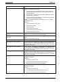
6.1 System Diagnostics - Codes and Messages..............................................................................................6-1
Status Messages (001-199) ................................................................................................................6-2
Warning Messages (201-399) .............................................................................................................6-3
Shutdown Messages (400 - 599).........................................................................................................6-4
Fatal System Errors...........................................................................................................................6-13
TRANS 01-D-specific Messages.......................................................................................................6-14
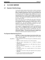
A CLC DDE SERVER
A-1
A.1 Dynamic Data Exchange .......................................................................................................................... A-1
The Dynamic Data Exchange Server ................................................................................................. A-1
IV
Contents
DOK-CONTRL-TRANS01D*RM-ANW2-AE-E1,44
TRANS 01-D
Dynamic Data Exchange Interface ..................................................................................................... A-2
A.2 The Communication Servers Main Window.............................................................................................. A-3
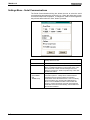
Settings Menu - CLC Server Configuration ........................................................................................ A-4
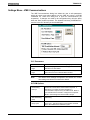
Settings Menu - Serial Communications ............................................................................................ A-6
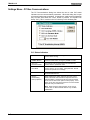
Settings Menu - VME Communications.............................................................................................. A-7
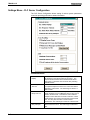
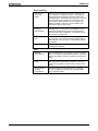
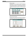
Settings Menu - PC Bus Communications ......................................................................................... A-8
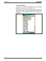
A.3 AT Modem Configuration Dialog............................................................................................................. A-11
A.4 SERVER Topic Name............................................................................................................................. A-12
B Direct ASCII Communication
B-1
B.1 Overview ................................................................................................................................................... B-1
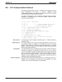
B.2 CLC Communication Protocol................................................................................................................... B-2
Reading Data from the CLC / TRANS 01-D ....................................................................................... B-3
Writing Data to the CLC / TRANS 01-D ............................................................................................. B-3
Communication Errors........................................................................................................................ B-3
Checksum .......................................................................................................................................... B-4
End of Message.................................................................................................................................. B-4
Backspaces and White spaces .......................................................................................................... B-5
Numeric Data Formats ....................................................................................................................... B-5
Format of Data Sent to the CLC / TRANS 01-D................................................................................. B-5
B.3 Command Classes/ Subclasses ............................................................................................................... B-6
Parameters ......................................................................................................................................... B-6
Variables............................................................................................................................................. B-6
Program Communication.................................................................................................................... B-6
I/O Registers....................................................................................................................................... B-6
B.4 Drive and CLC / TRANS 01-D Parameters and Subclasses .................................................................... B-1
Parameter Data Subclass................................................................................................................... B-1
Name Text Subclass .......................................................................................................................... B-1
Units Text Subclass............................................................................................................................ B-1
Upper Limit, L: Lower Limit Subclasses ............................................................................................. B-1
Attribute Subclass............................................................................................................................... B-1
Parameter Lists Subclasses............................................................................................................... B-2
SERCOS Parameter Sets .................................................................................................................. B-2
B.5 Parameter Lists......................................................................................................................................... B-3
Listing a Parameter ............................................................................................................................ B-3
Parameter List Block Transfer............................................................................................................ B-4
B.6 User Program Variables............................................................................................................................ B-1
'P': Data .............................................................................................................................................. B-1
'T': Label Text ..................................................................................................................................... B-2
B.7 Input/Output Registers .............................................................................................................................. B-2
I/O Register Access (RB), (RX), (RD) ................................................................................................ B-2
Set Current I/O State with Mask (RM) ................................................................................................ B-3
I/O Forcing Selection (RF).................................................................................................................. B-3
I/O Forcing State Change (RC) .......................................................................................................... B-4
DOK-CONTRL-TRANS01D*RM-ANW2-AE-E1,44
Contents V
TRANS 01-D
I/O Binary Forcing State (RS) ............................................................................................................. B-4
Erase All Forcing Masks (RE) ............................................................................................................ B-4
B.8 Communication Error Codes and Messages ............................................................................................ B-1
C Interbus Fieldbus Interface
C-1
C.1 Introduction ............................................................................................................................................... C-1
Topology ............................................................................................................................................. C-1
Data Objects....................................................................................................................................... C-1
Process Data Channel........................................................................................................................ C-1
Communications Channel .................................................................................................................. C-2
List of Data Accesses via Various Data Channels ............................................................................. C-2
C.2 Process Data Channel.............................................................................................................................. C-3
Default Configuration of the Process Data Channel of the Fieldbus Card ......................................... C-3
Application-Specific Configuration of the Process Data Channel....................................................... C-3
Process Data Input Description with Object 6000 .............................................................................. C-4
Process Data Output Description with Object 6001 ........................................................................... C-5
Monitoring the Process Data Channel of the Fieldbus Cards............................................................. C-6
Multiplex Channel ............................................................................................................................... C-7
C.3 Communications Channel......................................................................................................................... C-8
Direct Access to Data Objects............................................................................................................ C-8
C.4 Diagnosis on the Fieldbus Interface ......................................................................................................... C-8
Bit Assignment of Diagnostic Objects 5FF5 and 5FF6....................................................................... C-9
Bit Assignment of Diagnostic Objects 5FF0 and 5FF2..................................................................... C-12
CLC-D Diagnosis.............................................................................................................................. C-13
C.5 Interbus-S Slave Boards DBS03.1 or DBS 4.1....................................................................................... C-14
Applications ...................................................................................................................................... C-14
Function Overview ............................................................................................................................ C-14
Interbus-S Interface .......................................................................................................................... C-15
DBS03.1 Board Hardware ................................................................................................................ C-16
Appendix D Drawings
VI
Contents
D-1
DOK-CONTRL-TRANS01D*RM-ANW2-AE-E1,44
TRANS 01-D
1
Introduction
1.1
TRANS 01-D Control
The TRANS 01-D is designed for operation under control of a remote Line
Control ( such as a programmable controller ) which interfaces to the TRANS
01-D via the Cycle Interface ( DEA Card ) or through an I/O Network. The
TRANS 01-D will control three servo type axis and one spindle axis. The
drives will connect to the control via SERCOS ring. The I/O signals can be
received either through a DEA interface card ( if only Discrete I/O is used ) or
through an Interbus-S card (DBS 3.x).
Access to the TRANS 01-D’s controls, parameters and program is provided
at several different levels to allow for maximum security of machine
operations. For Operator security level access to the TRANS 01-D is provided
by a separate Cycle Interface ( DEA Card ). This allows certain manual
operations and does not require a CTA-10 ( Indramat provided MMI Interface
). For Toolsetter security level, the operator will have access to a CTA-10 and
can display current program, parameter and tool correction data. Another
level of security, via password, has been added to prohibit editing program
and parameter menus without prior authorization.
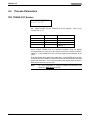
1.2
Technical Specifications
Number of feed axes controlled
three
Number of spindle axes controlled
one
Dimensioning system
inch or metric
Programming resolution
0.0001 inches; 0.001 mm
Maximum traverse
+/-838.8600 in; +/-8388.600 mm
Feedrate
programmable
Rapid traverse rate
programmable (parameter Aa10)
Jogging
Forward/reverse
Number of program blocks
up to 200
Repetition cycles/blocks
up to 99
Programmed tool position corr.
10 registers per axis
Dwell time
programmable from 0.01 to 99.99 sec
Auxiliary function outputs
w/DEA discrete I/O card
w/DBS (Interbus-S) I/O card
11 individually programmable on/off
7 individually programmable on/off
DOK-CONTRL-TRANS01D*RM-ANW2-AE-E1,44
Introduction 1-1
TRANS 01-D
1.3
Purpose of Manual
This is the user's manual for the Indramat TRANS 01-D motion controller. In
addition to this introductory chapter, it contains the following six chapters.
• CTA 10-1 Operation describes the man-machine interface that may be
used to control the TRANS 01-D.
• Programming describes the available G-code functions and the required
formats for other program functionality, and provides examples of
programming with the CTA 10-1.
• Parameters describes each parameter and the various methods that may
be used to modify them.
• I/O Functional Description covers the available interfaces to the machine
builder's equipment, and the power interrupt handling features of the
TRANS 01-D.
• Diagnostics describes the various status and other diagnostic messages
available on the TRANS 01-D.
Four appendices are also provided for the CLC DDE Server, Direct ASCII
Communication, Interbus-S I/O, and various engineering drawings.
1-2
Introduction
DOK-CONTRL-TRANS01D*RM-ANW2-AE-E1,44
TRANS 01-D
DOK-CONTRL-TRANS01D*RM-ANW2-AE-E1,44
Introduction 1-3
TRANS 01-D
2
CTA 10-1 Operation
The CTA 10-1 is the human-machine interface that connects to the TRANS 01D’s RS232/RS485 port (a wiring diagram for this connecting cable is in
Appendix A). The CTA 10-1 unit requires a 24Vdc supply.
2.1
Performing Tasks with the CTA 10-1
Though not a substitute for a PC, a CTA 10-1 provides a convenient means
to perform the following tasks:
• set operating mode under manual control
• select a connected axis for monitoring and control
• start and stop program cycle under manual control
• monitor actual position, following error, and velocity of the selected axis
• jog an axis under manual control
• view current diagnostic messages for the selected axis
• view or edit tool correction values
• view or edit parameter values
• view or edit current program
• easier setup and configuration of Indramat SERCOS power.
Once the TRANS 01-D has been set up and a program installed, the
operation of the control can be done via I/O inputs through the DEA card. It is
then possible to disconnect the CTA 10-1 HMI and connect it to another
TRANS 01-D without disrupting the operation of the first TRANS 01-D.
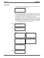
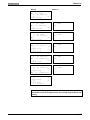
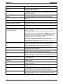
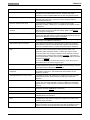
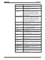
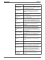
2.2
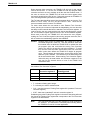
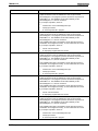
Display and Keypad Overview
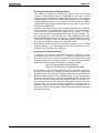
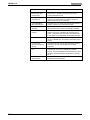
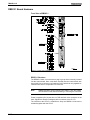
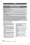
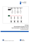
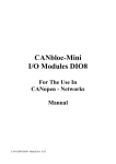
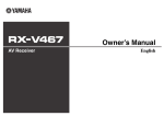
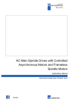
The human-machine interface is not menu driven; it is driven by the keypad of
the CTA 10-1. Figure 2-1 shows the displays that are available for controlling
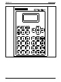
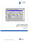
aspects of the TRANS 01-D. Figure 2-2 shows the CTA 10-1 keypad. Table
2-1 lists the various keys and which functions they control.
Initialization
Display
Trans 01-D
CTA10*-T01-01V30
CLC-D 2.1 262564
CLC*DP-T01-05V26
<P>
Parameter Mode
1.Input Param
2.Review
3.ESC
Input Parameters
1.Process Param
2.Axis Paramet
3.ESC
Review Parameter
1.Process Param
2.Axis Paramet
3.ESC
<N>
Programming Mode
1.Program Entry
2.Review
3.ESC
Axis Monitor
Display
1
C
Y
C
N000
Act=
Dev=
Vel=
Menu
Manual Mode
1.Hand
2.Continuous
3.Single Block
4.Single Cycle
Tool Offset
Z-Axis
± 0.00000
± 0.00000
± 0.00000
Diag
System:
_-Axis:
Task A:
AXIS
T__=0.000000
T__=0.000000
T__=0.000000
T__=0.000000
Task B:
Select Axis-Axis
1.X-Axis
2.Y-Axis
3.Z-Axis
4.S-Axis
Inputs:
Outputs:
o
o
o
o
p
p
p
p
op
Figure 2-1: Keypad-Driven Displays on the CTA 10-1
DOK-CONTRL-TRANS01D*RM-ANW2-AE-E1,44
CTA 10-1 Operation 2-1
TRANS 01-D
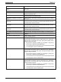
Figure 2-2: CTA 10-1 Keypad
2-2
CTA 10-1 Operation
DOK-CONTRL-TRANS01D*RM-ANW2-AE-E1,44
TRANS 01-D
Key
Function
ESC
Menu
Key
The <ESC> key clears any data in a
numerical field, or backs up to the
previous menu.
In Auto mode, the <Menu> key is
disabled.
In Manual mode, this key allows selection
of one of four operating modes, Hand,
Continuous, Single Block, and Single
Cycle.
Diag
P
N
Function
0
JOG
In Auto mode, the <Stop> key’s LED is lit
when the cycle has been stopped.
In Manual mode, this key stops the cycle.
In Auto mode, both the forward and
reverse<Jog> keys are disabled.
The <Diag> key displays messages
indicating any current diagnostic
condition. The arrow keys are used to
scroll between System-level, Physical I/O,
Task A, Task B, and connected Drive
diagnostics.
The <blank> key returns the display to the
Main Menu.
In Auto mode, the <Tool Offset> key
allows viewing of tool correction values.
In Auto mode, the <Home> key is
disabled.
In Manual mode, this key allows the user
to enter tool correction values.
In Manual mode, this key homes the
selected axis or moves it the current
reverse vector.
In Auto mode, the <P> key is disabled.
➪
The <Save> key saves the current
program block.
CLEAR
The <CLEAR> key’s LED is lit to indicate
an error has occured. This key should be
pressed to attempt to clear the error.
In Manual mode, this key accesses a
short list of parameters for editing.
In Auto mode, the <N> key allows review
of the currently executing program block.
In Manual mode, this key allows review or
editing of the current program, block by
block.
Within menus, the arrow keys are used to
scroll up or down.
In Manual mode, the <Feedrate Override>
key’s LED is lit to indicate that the the axis
can be jogged at its rapid jog speed. This
key is only enabled after the axis has
been homed.
The <Axis> key is used to select an axis.
AXIS
CR
CTA 10-1 Reinitialization key sequence:
<ESC>+<CR>
Access to Text Window for Serial Port
Messages: <CR>+<Menu>.
In Auto mode, this key is disabled.
1
In Manual mode, the <Start> key starts
the cycle.
In Auto mode, this key is disabled.
ENTER
In both modes, this key’s LED is lit to
indicate a program is running.
In menus, press the <Enter> key to select
the blinking option.
When editing parameter or tool correction
values, press this key to load the new
value.
When editing a program, press this key
load the data and move the cursor.
Table 2-1. Keypad Functions.
DOK-CONTRL-TRANS01D*RM-ANW2-AE-E1,44
CTA 10-1 Operation 2-3
TRANS 01-D
2-4
CTA 10-1 Operation
DOK-CONTRL-TRANS01D*RM-ANW2-AE-E1,44
TRANS 01-D
3
Programming
This chapter contains:
• Overview of all possible G code functionality that will be available on the
TRANS 01-D.
• A discussion of required programming formats for each type of function
which can be selected.
• A description of the procedures required for entry of each possible type of
program line.
3.1
Enabling Program Changes
Because it is important to protect the part program from accidental or
unauthorized alterations, program changes must be enabled as follows:
1. Portable CTA-10 -- Connect the serial cable from the CTA-10 to the
selected TRANS 01-D.
2. Establish communication between the CTA-10 and the selected
TRANS 01-D.
3. Enter the Password to enable Program Entry/Edit Mode. The current
password is pre-set at 1234.
DOK-CONTRL-TRANS01D*RM-ANW2-AE-E1,44
Contents
3-1
TRANS 01-D
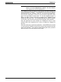
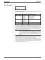
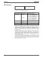
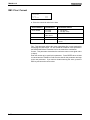
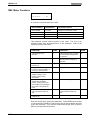
3.2
Programming Capability Description
The TRANS 01-D has 200 programmable NC Blocks. The following functions
can be programmed in each NC Block, depending on which parameters are
selected.
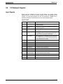
NC CODE
FUNCTION
G00
Rapid Feed Positioning
G01
Programmed Feedrate Positioning
G04
Dwell time
G08
Adaptive Depth
G20
Re-enable Axis
G21
Disable Axis
G36
Rotary Positioning - Shortest Path
G37
Rotary Positioning - Positive Direction Only
G38
Rotary Positioning - Negative Direction Only
G61
With Lag Finishing
G62
Without Lag Finishing
G69
Home to a Positive Stop
G74
Homing
G75
Enable Feed to a Positive stop
G76
Disable Feed to a Positive Stop
G90
Position command - Absolute (Destination)
G91
Position command - Incremental (Distance)
X, Y, Z
Axis designation
F
Feedrate or Dwell Time
T
Tool Correction register number to be used
S
SERCOS spindle RPM speed (Must be enabled in Parameters)
P
Spindle position
M
Auxiliary functions
Jx
Program jumps:
JN
-- Unconditional jump
Ju
-- Jump to subroutine
JR
-- Reverse vector programming
JS
-- Jump and stop
JC
-- Conditional jump
JW
-- Conditional Jump with a Wait Time
JReturn-- Return from subroutine
Table 3-1: Available Program Functions
3-2
Contents
DOK-CONTRL-TRANS01D*RM-ANW2-AE-E1,44
TRANS 01-D
3.3
Application Programming Requirements
Remote operation of the TRANS 01-D via the Operator Interface requires that
certain rules for machining, reverse movements and tool change programs must
be established and scrupulously observed by the programmer. This is necessary
to insure that program execution will always be started in the proper manner,
independent of unexpected events and actions, and that the system will always
remain controllable in all operating situations via the Operator and Cycle
Interfaces. If the programming rules are not obeyed, the TRANS 01-D will,
depending on the type of violation, refuse to issue a Ready signal for the start of
automatic operation, or it will not be possible to execute a homing command or
manual operation selected from the Operator Station. The various programming
situations and the requirements for each are summarized in the following
sections.
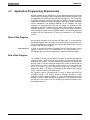
Start of the Program
All machining programs must start with NC Block 000. If several different
machining programs are to be written, branching must be accomplished such
that an unconditional or conditional jump from NC Block 000 will be executed
to jump to the start of the program.
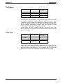
First Positioning
In order to assure that machining programs will be executed with a correct
absolute reference under all circumstances, the first positioning in a
machining program should be programmed in Absolute Positioning Mode.
End of the Program
The TRANS 01-D user has the ability to program Incremental and Absolute
positional moves. These moves can be executed in program NC Blocks With
or Without Lag Finishing. The G62 (Without Lag) command in a program NC
Block is used for velocity contouring between the current NC Block and the
next program NC Block. Because of this contouring, the last motion NC
Block in a profile, must be programmed With Lag Finishing (G61).
Additionally, when a NC Block is programmed with Without Lag Finishing
(G62), it cannot contain any NC Block jumps.
All programs must be terminated with a Jump To Block 000 And Stop
command (JS000). This applies equally to machining programs, reverse
programs, and tool change programs. It is very important that all programs
end with a Jump To Block 000 And Stop command. The TRANS 01-D uses
this signal for many items, such as monitoring of thermal overloads, Home
Switch Monitoring, etc.
DOK-CONTRL-TRANS01D*RM-ANW2-AE-E1,44
Contents
3-3
TRANS 01-D
Axis Enable and Disable (G20, G21)
If the machine process requires the servo axis to be enabled and/or disabled
during the process, the G20, G21 commands allow this enabling/disabling to
be done under part program control. This adds greater control and flexibility
for the axis being used. The G20 and G21 commands are available for all
types of axis in the TRANS 01-D system. When the user programs the
specified axis with a G21 command, the axis will be disabled. The status of
the servo drive will change from AF (enabled) to Ab (ready for operation, but
with no torque on the motor). This disabling will remove the current flow to
the servo motor. The axis is still monitored in the TRANS 01-D system, but
no additional motion commands can be given to the disabled axis or an error
will result.
To program the Axis Enable/Disable commands, the entered G-code, either
G20 or G21 must be followed by the axis to be enabled/disabled. Ex: N021
G21 X0. A numerical value must follow the axis designation (X, Y or Z), or
the TRANS 01-D program syntax checker will issue an error. However, the
numerical value following the axis is ignored by the TRANS 01-D during
program execution. The same program syntax must be followed for the G20
command. Subsequent program blocks can be executed using the other axis
in the system while an axis is disabled, but the disabled axis cannot be
programmed with any additional motion blocks until the axis has been reenabled.
Note:
3-4
Contents
For information specific to Clamping a rotary axis using G20 and
G21, refer to the Rotary Motion Control section.
DOK-CONTRL-TRANS01D*RM-ANW2-AE-E1,44
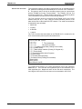
TRANS 01-D
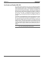
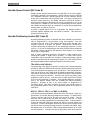
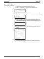
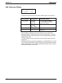
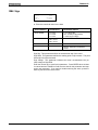
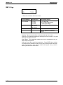
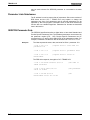
Basic Homing Program
When incremental feedbacks are used, a homing program for travel to the
reference position is required at NC Block 195. It must conform to the
following requirements:
1. No instruction for travel to a particular position is permitted if there is no
prior instruction for homing.
2. The program must always contain a Homing instruction (Block 195 is
Default NC Block).
3. The program must always be terminated with a Jump To Block 000 And
Stop instruction. The simplest such program in NC Block 195 could be
Homing at a feedrate of 100 UPM (Units per Minute) with a Jump to Block
000 and Stop.
Note:
Absolute feedbacks, when used in TRANS 01-D systems, do not
require homing, but any profile used to return the axis to its home
position should begin in Block 195.
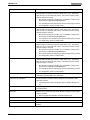
N195
G74
Z0.000 F100
J S 000
Block 195 = D efaultN C Block for
hom ing program
H om ing com m and
Zero offset= 0
Feedrate = 100 U PM
J specifies Jum p
S specifies Stop
TargetN C Block = 000
Figure 3-1: Simple homing instruction
The homing program must be designed so that safe retraction is possible
under any condition, including power shutdown. To insure this, the TRANS
01-D has been provided with "reverse vectors" which will determine the NC
Block number to which the program will jump if a Homing (Reverse)
command is issued in Manual or Automatic modes.
The
DOK-CONTRL-TRANS01D*RM-ANW2-AE-E1,44
Contents
3-5
TRANS 01-D
Reverse Vector is initially set to NC Block 195, but can be changed to any NC
Block number in the machining program. Each time the TRANS 01-D
executes a Jump To Block 000 And Stop, the reverse vector is reset to 195.
The reverse vector number is retained even if a power failure occurs.
As described in the section titled, "Auxiliary Functions (NC Code M)",
auxiliary outputs can be issued at various points in the program and the
TRANS 01-D waits for an acknowledgment for each output turned on or off
before it executes the next NC Block. The one exception to this is that a
jump to a reverse program is performed even if the acknowledgments do not
match their associated outputs, provided that the first NC Block of that
program performs only auxiliary output functions. (This is useful for an
emergency return or upon recovery from a power failure.)
This first NC Block in the reverse program (usually 195) should force the
auxiliary outputs into a state where they match their acknowledgments. The
next NC Block then will usually be a homing command. This should only be
performed if it is indeed safe to force auxiliary outputs off and move.
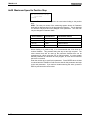
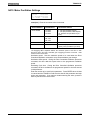
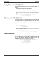
Homing and Zero Offset (NC Code G74 & G69)
G74 Standard Homing
When G74 Homing is selected during dialog programming, the CTA 10 will
display ZERO OFFSET? Note that a reference value is entered as a system
parameter (Ax13). This reference value is used to establish the machine
reference point as some point other than Home, such as the center point of
the slide. If all references to the part are to be programmed with respect to
this machine reference point, a zero offset value of 0 must be entered.
However, if the measurements in the program are to be programmed with
respect to some other reference, such as the face of the workpiece, the
distance from the machine reference point to the workpiece reference point is
entered as the zero offset, providing a new reference point which is offset
some specified distance from the machine reference point.
The value entered as the zero offset is added to the reference position after
homing has occurred. Thus, the zero offset can be used by the programmer
in order to program the measurements in a machining program with respect
to one of the surfaces of the work piece.
In order to assure correct measuring references, programs which use zero
offset referenced measurements must be started with a homing instruction
which sets the corresponding zero offset.
Note that the control is at Home when the slide is at the position where the
first marker pulse (zero pulse) occurs after closure of the Home Limit switch,
and that no movement of the slide will occur when programming a zero offset.
The zero offset provides the flexibility to change the reference point whenever
a different part is handled on the TRANS 01-D transfer line, or to correct
differences between actual and designed Home position.
Note:
3-6
Contents
For information specific to Homing a rotary axis, refer to the
Rotary Motion Control section.
DOK-CONTRL-TRANS01D*RM-ANW2-AE-E1,44
TRANS 01-D
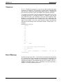
G69 Home to a Positive Stop
Home to Positive stop is a feature used for convenience to initialize the
position of an Indramat multi-turn absolute feedback. This is a requirement
encountered in the commissioning of machines using absolute feedback
devices.
When first installed, or whenever the feedback-to-machine
orientation is disrupted, the feedback will report a position that is not relevant
to the actual machine state. A method must be available to orient the
machine to a known position, then load the absolute feedback with that value.
SERCOS equipped Indramat drives contain a feature that allows this via the
setting of a SERCOS procedure. The SERCOS Ident used is P-0-0012. This
function is also available in Indramat’s Visual TRANS software, in easy to use
graphic screens. G69 offers an alternative method to perform this orientation.
It achieves this by moving the slide in the following sequence:
1. The axis moves in a parameter-dictated direction until a stalled-motor
condition is detected; that is, a positive stop is found. The length of this
move is limited to the total travel distance as defined in the travel limit
parameters (Aa06), plus 10%. If the stop is not found in this distance, an
error results.
2. The axis reverses direction and moves away from the stop a distance
equal to the value programmed in parameter Aa22 (“Home to Stop
Distance”).
3. When the axis has reached the above position, the absolute encoder
value is reset to the value stored in the Reference Position parameter
(Aa13).
Note:
G69 is intended for use only during initial machine commissioning,
or when alterations have been made to the drive train that destroy
the relationship between the absolute encoder and the actual
machine position. This could occur for example during removal of
the motor, gearbox, or ballscrew. A move to a positive stop is not
always a repeatable function. Changes in drive train temperature,
friction, or compliance, as well as contamination in the area of the
stop (such as cutting chips), can cause the relationship between
actual slide position and the absolute encoder setting to be
different between two homes to positive stops. For this reason,
axis position should be accurately checked after the operation.
Note:
G69 should not be programmed as a machine operator accessible
function. It should only be accessible to maintenance personnel.
During machine commissioning, it is advisable to disable the
function via parameter Aa12 after the absolute feedback is set, to
prevent unintentional repeats of the function afterwards. An
alternative to this function is to use the absolute encoder
initialization routine available in Visual TRANS software.
Note:
Do not program a G69 function in the default block for homing
(N195). This will cause the TRANS to execute the procedure
every time the TRANS-01 is commanded to return, resulting in
possible position errors. See warnings above.
DOK-CONTRL-TRANS01D*RM-ANW2-AE-E1,44
Contents
3-7
TRANS 01-D
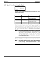
Associated Parameters
Aa11: Directions
The homing direction parameter will determine the direction the axis will
move when first searching for the positive stop. A ‘0’ programmed in
this parameter will cause the axis to search in the “plus” direction. A ‘1’
will cause the axis to search in the “minus” direction.
Aa12: Homing Reference
This parameter indicates the method used to determine the initial home
position. Home to a Positive Stop is enabled here, by selecting option
‘4’.
Aa14: Reference Position
This parameter contains the absolute value that should be used for
home position when it is found. The actual position register is loaded
with this value at the end of a G69 function.
Aa20: Positive Stop Feedrate
Aa20 contains the maximum feedrate that can be programmed when
executing any positive stop functions. This also applies to G69, Home
to Positive Stop.
Aa21: Positive Stop Torque %
This two-part parameter indicates the percentage of available torque the
motor should be limited to when (1) Approaching the positive stop (“To
the Stop”), and (2) once the positive stop is detected (“At the Stop”).
These values are used for both Move to Positive Stop (G75) and Home
to Positive Stop (G69).
Aa22: Home to Stop Distance
During a G69 function, the TRANS-01D uses this parameter to
determine the distance the axis should move away from the positive
stop, before stopping and setting reference position. The value is nonsigned, as the direction is determined by the inverse of the state of
parameter Aa11.
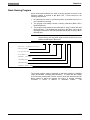
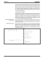
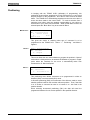
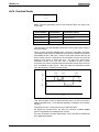
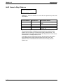
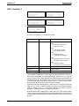
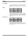
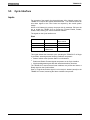
Programming
G69 is programmed similar to any move command.
Required block contents:
3-8
Function:
G69 is entered into the block as the block function.
Axis Word (X, Y, or Z):
The block must contain the axis-word for the desired axis. The axis word must
have a value associated with it equal to zero (example: “X0”). Zero offsets, such
as those available with G74, are not available with G69. Zero Offsets are used to
temporarily change axis offsets, as an aid to simplify part programming for
multiple parts. G69 is intended for machine commissioning and repair only, and
therefore should not be used to temporarily change axis co-ordinates. Only one
axis is allowed per G69 operation.
Feedrate (F):
It is suggested that a feedrate always accompany a G69 function in a block for
clarity and safety. The feedrate entered must be less than or equal to the value
entered in Axis Parameter Aa20 (“Maximum Speed to Positive Stop”), or an error
will result during execution. If no feedrate value is entered, the TRANS 01-D will
default to the value in Aa20 (max. speed to positive stop).
Lag Finishing:
G69 always operates with G61 (“With Lag Finishing”). An error will result if an
attempt is made to execute a G69 function with G62 (“Without Lag Finishing”)
active. G62 is a modal value, however, it is recommended that G61 always
accompany a G69 move for clarity and certainty.
Contents
DOK-CONTRL-TRANS01D*RM-ANW2-AE-E1,44
TRANS 01-D
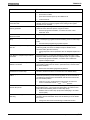
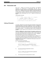
N190
G69
G61
Z0.000 F10
J S 000
Block Number (e.g., 190)
Homing to a positive stop command
With Lag Finishing
Axis to be initialized
Zero offset = 0
Feedrate = 10 UPM
J specifies Jump
S specifies Stop
Target NC Block = 000
Figure 3-2: Example Program Block
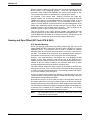
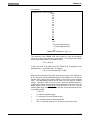
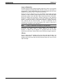
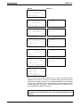
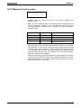
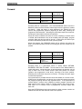
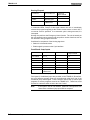
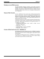
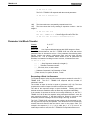
Operation
Using the previous example (N190 G69 G61 Z0 F10 JS000), with the
following parameter conditions:
• Aa06: Overtravel Limits: = +20.000 and -0.400
• Aa11: Directions - Homing = 1 (Find stop in Negative Direction)
• Aa14: Reference Position = 4.000
• Aa22: Home to Stop Distance = 0.500
The motion profile would be as follows:
-
+
Directions
Starting Point
F=10 UPM
Step 1: Move to Positive Stop
F=10 UPM
Step 2: Move out “Home to Stop Distance”
Final “Reference Position”
Value of position is 4.000
Figure 3-3: Example Motion Profile
Note:
Step 1 will attempt a move of 22.44. ([+20 - -0.4]*1.10). If the
positive stop is not found in this range, a “Positive Stop Missing”
error will result.
Note:
Any subsequent G74 (homing) commands would move to the
position defined here as “reference position”. Any Zero offset
value in them would be added to the value of the reference
position parameter after reaching this point, and its value would
change to that result.
DOK-CONTRL-TRANS01D*RM-ANW2-AE-E1,44
Contents
3-9
TRANS 01-D
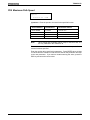
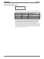
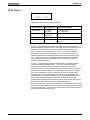
Positioning (NC Code G00, G01, G90 & G91)
G00 and G01 specify that a positioning move will be executed in this program
NC Block. G00 specifies the speed to use for the commanded move will be
at the Rapid Speed entered into the axis parameter . In this case, a Feedrate
is not required in this NC Block. G01 specifies a positional move, but the
programmer is prompted to enter a Feedrate value to be used for this move .
If the programmer does not enter a Feedrate in this NC Block, it will be
executed using the last feedrate value used for a positional move.
Two types of positioning can be selected in the system, absolute (G90) and
incremental (G91).
Note:
For information specific to Positioning a rotary axis, refer to the
Rotary Motion Control section.
In absolute positioning (G90), all movements of the slide are made to some
absolute distance from the machine reference position, which will either be
Home or some offset position from Home. Thus, if the slide is at +2 inches
from Home, a command to travel to +3 inches results in a one inch feed in
the positive direction.
In incremental positioning (G91), all movements of the slide are made in the
commanded direction to the distance specified, starting from the current
position of the slide. Thus, if the slide is at +2 inches from Home, a
command to travel +3 inches incrementally results in the slide positioned at
+5 inches from Home.
With / Without Lag During Positioning (G61 & G62)
When a position command is issued, the servo motor moves the axis in
response to that command. There will always be some finite lag time
between the time the command is issued and the time the servo motor brings
the axis into position. It is important to note that, in a program NC Block, the
TRANS 01-D does the positioning first, then performs any miscellaneous
functions such as jumps or turning auxiliary functions on or off when it
finishes the movement.
When programming your positioning commands, you will be required to
respond to the "With/Without Lag?" display.
With Lag Finishing (G61) specifies that the axis must be in position before
any miscellaneous functions remaining in the NC Block are executed or
before the next NC Block is executed. This would be required at full depth,
for exampleIt is important to note that this is also required where you have
programmed miscellaneous functions, such as auxiliary outputs (see the
section titled "Auxiliary Functions (NC Code M)" for more information) which
are to turn on only when the axis is in position.
Without Lag Finishing (G62) specifies that the velocity profile will be
contoured from one NC Block’s feedrate to the next NC Block’s feedrate to
avoid a stoppage of motion between NC Blocks. The position programmed in
a G62 NC Block will be the position at which the axis has reached the next
NC Block’s feedrate. The move is considered to be finished once the axis is
accellerating/decelerating into the subsequent feedrate, but prior to the time
the position is actually reached. Thus, any auxiliary functions in this NC Block
may be turned on while the axis is still in motion. Therefore, With Lag
Finishing may not be necessary to your positioning operation, but you may
need to select it to insure that auxiliary functions are not turned on too soon.
3-10
Contents
DOK-CONTRL-TRANS01D*RM-ANW2-AE-E1,44
TRANS 01-D
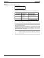
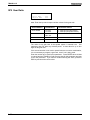
Enable/Disable Feed To A Positive Stop (G75 & G76)
This function may be used when it is necessary to position the slide against a
positive mechanical stop. The slide will move at the feedrate programmed in
this block. The available torque of the motor will be reduced to the
percentage value specified in parameter Aa21, "% Torque To Pos Stop".
When the Trans 01-D senses that the motor has stalled, the motor's available
torque will be changed to the percentage value programmed in parameter
Aa21, "% Torque at Pos Stop". This torque value will still be used for any
Dwell or other waiting period, i.e., auxiliary function acknowledgments. The
torque value will be switched back to its previous value when the Trans 01-D
executes a G76 program command.
The distance (G91 incremental) or destination (G90 absolute) programmed
with this function is the maximum distance the slide will be allowed to travel
and should be a point just past the expected positive stop. If the slide
reaches this position without the motor stalling, movement will stop, the
diagnostic POS STOP MISSING will be displayed and a soft fault will result.
To recover, you must press the CE (Clear Error) key. An incremental
distance (G91 command) programmed in a block following a feed-to-positivestop will be based on that point where the stall occurred.
If the theoretical programmed position is too close to the positive stop, the
error message 'Positive Stop Missing' will be displayed.
The TRANS-01-D will recognize the positive stop in two ways. 1) The
feedback velocity falls below 1% of the commanded velocity and 2) the torque
value exceeds the pre-set value in parameter Aa21 - % Torque to the Stop for
48 mS. If both of the aforementioned situations occur together for 120 mS,
the TRANS 01-D will consider the positive stop as found. It will then reduce
the drive’s torque level to the value set in Aa21 - % Torque at the Stop.
When the theoretical end position of the G75 block is programmed, the
theoretical end position should be at least four times the following error past
the mechanical positive stop. The following error is calculated as follows:
Following Error = Programmed speed in G75 block/Kv factor (Aa08) * 1000.
DOK-CONTRL-TRANS01D*RM-ANW2-AE-E1,44
Contents
3-11
TRANS 01-D
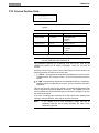
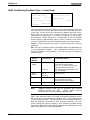
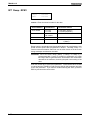
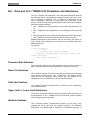
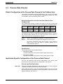
Adaptive Depth Control (G08)
Adaptive Depth arises from the final depth of a positional move being
dependent on the location of the part surface and not the referenced position
of the motor encoder. This is made possible by using an external encoder to
determine the final position. This form of positioning has the following
advantages:
• It compensates for both drive-train and work piece variations while the tool
is actually performing the cut.
• Using incremental positioning it’s possible to program distances relative to
the face of the part.
The TRANS 01-D begins adjusting the final depth of a positional move using
the secondary device when a G08 ( Adaptive Depth Command ) is issued in
the NC block of the part program. This G08 command must be preceded by a
G62 ( without lag command )
In an ideal situation once a G08 command has been issued the drive will
continue to move until the position reading from the External Encoder ( EE )
is equal to that of the G08 command. But the final position also takes into
account whatever minimal deflection that may have existed ( e.g. due to
vibration, mechanical bindage etc. ) on the EE. To do this the TRANS 01-D
takes a snap-shot of the EE feedback position when it reaches the first NC
block containing a G62 move preceding a G08 NC part. In reality the final
positional reading of the EE equals the deflection seen on the EE when the
first G62 NC block preceding a G08 was issues plus the distance
commanded in the G08 NC block.
The final destination point of this G62 move must be such that the EE has
been depressed by at least 50 micro-meters and not more than the value set
in TRANS 01-D Axes Prm # 31 ( Linear Encoder Pre-Limit ).
If the value of the position in the final G62 block plus the position value
located in the G08 block is greater than the value in TRANS 01-D Prm # 6 an
over travel fault ‘ Position out of bounds ’ will occur.
Once the TRANS 01-D is in any other NC block other than one that contains
a G08 command then the EE is not being used for positioning.
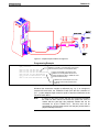
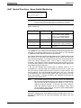
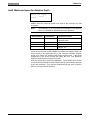
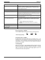
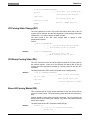
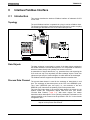
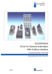
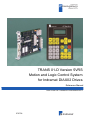
Hardware and Software Requirements
3-12
Contents
Indramat Servo Drive
DIAX 03 Type Drive
Firmware
TRANS 01-D 05V44 or higher
DIAX 03 Drive DSM 2.2 ELS 04V28
Indramat Interface Card
DLF (latest revision)
Indramat Encoder Cable
Type 03-0349
Online Programming Tool
Indramat Visual TRANS software
External Linear Encoder
Heidenhain MT25W (incremental measuring
device)
DOK-CONTRL-TRANS01D*RM-ANW2-AE-E1,44
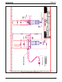
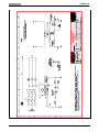
TRANS 01-D
Figure 3-4: Adaptive Depth Hardware Arrangement
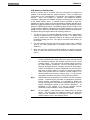
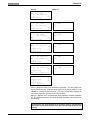
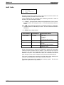
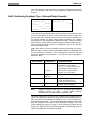
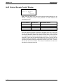
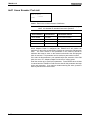
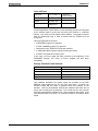
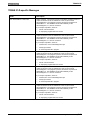
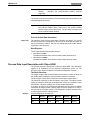
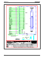
Programming Example
At Z=10 the TRANS 01-D takes a snap shot of the
N000 JC005:001
deflection on the EE. This will be taken into account
......
when the EE is to position 0.5 units (Block N012).
N009 G01 F90 G61 Z10 F100
N010 G01 G90 G62 Z20 F200
At Z=27 the TRANS 01-D expects to see
N011 G01 G90 G62 Z27 F50 M22200010000
deflection on the EE greater than 50 micro
N012 G08 G91 Z.5 F10 M22200010001
meters and less the value in TRANS 01-D #31
N013 G04 F0.20 M22210010000 JS000
......
(Linear Encoder Pre-limit).
N195 G74 Z0 F100 M00010000000 JS000
TRANS 01-D moves a depth of 0.5 units
on the EE from the EE's position at NC
block 10.
Figure 3-5: Jump On Event Programming Example and Program Sequence
Whatever the amount the encoder is deflected (e.g., by λ) as it begins to
execute NC block N012, the TRANS 01-D will move the axis a distance of
(0.5 - λ) under adaptive depth control to equal 0.5 total linear deflection at the
end of NC block N012.
Note:
DOK-CONTRL-TRANS01D*RM-ANW2-AE-E1,44
If motion on the probe occurs after the G62 command preceding
the G08 has been issued, but before the probe has come in
contact with the part then this positional variation will not be
accounted for by the TRANS 01-D. But this error will be
accounted for once the probe moves onto the part (unless there is
physical damage to the EE).
Contents
3-13
TRANS 01-D
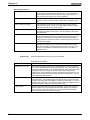
Set-up Procedure
1. Ensure that the DIAX 03 drive system is powered off. Install the DLF
board.
2. Attach the Heidenhain External Encoder to the DLF board using the
Indramat 03-0349 cable.
3. Power up the DIAX 03 drive system.
4. Start communicating with Visual TRANS ( using RS232 ) through the
serial port “ X27 ” on the CLC-D card on the DIAX-03 drive.
5. Using Visual TRANS check that SERCOS prm “ S-0-0030 Manufacturer
Version ” displays the correct version of DSM -“DSM 2.3-ELS-04V28”.
6. The DIAX 03 has to be configured in Metric ( TRANS 01-D Axes prm # 2
) for this particular version of DSM firmware.
7. CLC-D card prm # “ C 0-0306 In position window ” needs to be set to “
.001mm ” to ensure that the DIAX 03 drive and EE home correctly.
Configuration Procedure
1. Put the TRANS 01-D into prm mode.
2. TRANS 01-D Axes prm # 1 Part 2 needs to be a “ 1” to activate the G08
(Adaptive Depth Command) in the NC part program block. If a G08 is
used in a program without this prm activated the following alarm appears:
“ 779 Adaptive Depth not configured for this axis ”
3. TRANS 01-D Axes prm # 3 ( Feed Constant ) needs to contain an
accurate value, of the axis ballscrew that the Adaptive depth is being
programmed on, as this value is used to ensure consistency between the
Motor Encoder feedback and the External Encoder feedback.
4. TRANS 01-D Axes prm # 30 ( Adaptive Depth Max Speed ) needs to be
set to maximum allowable velocity when programming a G08 ( Adaptive
Depth Command ). Using Visual TRANS this prm corresponds to Axes
Prm # 317. If a value greater than this prm is programmed in a G08
command block the following alarm appears: “ 780 Maximum Adaptive
Depth feedrate exceeded ”
5. TRANS 01-D Axes prm # 31 ( Linear Encoder Pre-limit ) contains the
value that the TRANS 01-D will compare to the EE position at the
beginning of the G08 NC block. If the position from the EE is greater than
Axes Prm # 31, the TRANS 01-D will move to the position within the
preceding G62 block plus the Pre- limit deflection value and then the
following alarm appears: “ System: 511 Adaptive Depth Pre-Limit Error ”
6. Using Visual TRANS make SERCOS Prm “ P 0-0075 Interface
Feedback 2 ” equal to “ 2 ”. This configures the DLF board as the source
of secondary feedback.
7. Exit from Prm Mode.
8. To ensure that the External Encoder is feeding information back to the
DIAX 03 drive, push the tip of the MT25W in & out. The position display
on SERCOS Prm “ S-0-0053 Position Feedback Value 2 Ext. Feedback ”
should change correspondingly.
3-14
Contents
DOK-CONTRL-TRANS01D*RM-ANW2-AE-E1,44
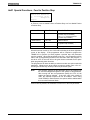
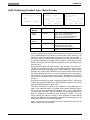
TRANS 01-D
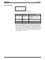
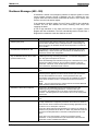
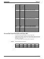
Alarm / Diagnostic
Number
Cause
Action Required to Reset
Condition
425
“Task B: 425 Depth: Probe reading >
w3; not zeroed (30)”
Ensure that CLC-D card prm C-0-0 306
In-Position Window is less than 50
micro meters.
When referencing the motor encoder (
performing a G74 ) the EE was not set
to a value less than 50 micro meters.
511
“Adaptive Depth Pre-Limit Error ”
The EE is deflected more than TRANS
01-D prm # 31 at the beginning of the
G08 part.
1. The part may be out of tolerance and
this is a correct diagnostic.
2. The Pre-Limit value in TRANS 01-D
prm # 31 is too small.
3. There is some mechanical blockage
with the EE.
512
“ Adaptive Depth Part Not Found ”
The TRANS 01-D has reached the
position commanded in the G62 block
preceding the G08 command plus the
Pre-limit value and still has not detected
more than 50 micro meters deflection
on the EE.
779
“ Adaptive Depth not configured for this
axis ”
A G08 was issued in an NC part
program block without TRANS 01-D
Axis prm 1 being enabled for Adaptive
Depth programming.
780
“Maximum Adaptive Depth feedrate
exceeded ”
The feedrate programmed in the G08 is
greater than the value in TRANS 01-D
Axes prm # 30.
781
“Maximum Adaptive Depth deflection
exceeded”
The distance traveled by the EE is
greater than TRANS 01-D Axes prm #
32
DOK-CONTRL-TRANS01D*RM-ANW2-AE-E1,44
1. The part may be out of tolerance and
this is a correct diagnostic.
2. Test to ensure data is being read
from EE by monitoring SERCOS prm S
0-0053 when EE is in motion. There is
an error in reading the EE data.
Problem with EE or Feedback cable or
DLF card
Make TRANS 01-D Axis prm 1 such
Adaptive Depth programming is
enabled.
Decrease the feedrate less then the
value in TRANS 01-D Axes prm # 30 or
increase this prm greater than the value
on the G08 command - depends on the
mechanical limitation of the system.
Either decrease the distance in the G08
NC block or increase the value in
TRANS 01-D Axes prm # 32 - need to
consider mechanical limitations.
Contents
3-15
TRANS 01-D
External Feedback Devices - Distance Coded Linear Scale
Note:
This information applies only to TRANS 01-D software versions
5V59 and later.
For the use of Distance Coded Linear scales, the operation of the TRANS 01D will remain the same except for the following cases:
• When referencing for the first time after powering up or in those instances
where the axis has lost its reference.
• When executing a Home command (G74) when the axis is referenced
• When the user has made changes to the Reference position since the last
time it was Homed or Referenced.
Relevant parameters for Distance Coded Linear scales include:
• S-0-0115 Position Feedback Type (set second LSB to 1 to set distance
coded linear scale as feedback type for servo drive)
• S-0-0118 Resolution of Linear Feedback
• S-0-0165 distance coded linear scale
Dimension 1
Distance-coded Reference
• S-0-0166 distance coded linear scale
Dimension 2
Distance-coded Reference
• S-0-0178 distance coded linear scale Absolute Offset 2
Operation of Servo Drive with Distance Coded Linear Scale
The Distance Coded Linear scale is a hybrid device that initially acts like an
incremental feedback device, but once it is referenced to the machine
position grid, it will act as an absolute feedback device. The advantage of the
Distance coded scale is the user does not have to re-establish a Home
position, it only needs to establish where it is in relation to the machine
reference point if axis reference is ever lost.
On power-up or when axis has lost its reference, the system will not be
referenced. S-0-0403, LSB will be 0. When a Drive Generated Homing
Command is issued, the axis will traverse the distance necessary to pass two
marker pulses, in the direction specified in the Homing Parameter as the
Homing direction. After it has traversed this distance, it will stop moving and
display its absolute position as defined by the scale. At this time the servo
drive will set S-0-0403, LSB to a 1 to signal that the axis is referenced. Any
subsequent Drive Generated Homing Commands that are issued will be
ignored by the drive.
3-16
Contents
DOK-CONTRL-TRANS01D*RM-ANW2-AE-E1,44
TRANS 01-D
TRANS 01-D Operation
The TRANS 01-D treats the Distance Coded Linear scale as an incremental
feedback device in those cases where the axis will loose its reference, i.e.:
Exiting parameter mode, certain drive errors, or when the system has lost all
power. In these cases, if reference is lost, the G74 command initiates a Drive
Controlled Homing Procedure to once again reference the scale to the
machine slide.
If the axis has not lost its reference, the G74 command moves the slide to the
already established Home position. When the axis has been moved to its
established Home position, the Home output from the TRANS 01-D Cycle
interface goes high.
If the user has changed the value of the TRANS 01-D Reference position by
changing the value of the axis word in the Homing Block, the system does not
re-establish the Home position, unless it has lost reference. However, it does
move the axis to the newly designated Home position and output the Home
signal to notify the line control that the axis is at the Home position. If the
Reference position parameter value has been changed, the TRANS 01-D
once again issues a Drive Generated Homing Command to re-establish its
Home position.
The user should enter the value to be displayed when at the Home position
using the already established methods, Axis word in the G74 Homing block
and by entering a value into the Reference Position parameter (CTA-10 Aa13
or Axis parameter A-0-0318). These two values are summed and placed into
S-0-0054 (Position Feedback 2, Reference Distance) as the value to be
displayed when at the Home position.
DOK-CONTRL-TRANS01D*RM-ANW2-AE-E1,44
Contents
3-17
TRANS 01-D
Rotary Motion Control
The TRANS 01-D executive software is configured to include the ability to
control a rotary application. This option can be used for applications such as
rotary tables or lift and transfer drives. The software will allow programming
rotary positions in UNITS/TABLE REVOLUTION. Rotary speeds are also
entered in these same units.
Note:
The TRANS 01-D can only be configured to control one rotary
axis. When used in a multi-axis system, only one of the axes may
be rotary.
Rotary software uses conventional TRANS 01-D programming techniques.
Only certain motions and/or working units change. The program commands
G20 and G21 are functional in rotary operation.
Associated Parameters
Since the system of units for rotary motions is arbitrary, the UNITS parameter
gives the user the option of specifying the UNITS/TABLE REV to be used for
his application. The software and/or hardware Travel Limits can be used to
limit the motion to less than one revolution. As an example, the motion on a
typical rotary crank arm transfer drive should not travel greater that 180° for
its total travel. Using the Travel limits, any motion outside of 270° - 90° will
cause an Overtravel fault.
The standard parameters used for Rotary operation are described below.
Parameter
Description
A02
UNITS /TABLE REVOLUTION
A05
GEAR RATIO
A10
SPEEDS -- Homing Speed, Rapid Speed, Jogging Speed,
Jogging Rapid, Max Cutting and Max Speed to Positive Stop
are all expressed in unit/table rev/min.
A11
DIRECTIONS:
Homing Direction: Determines the direction the axis will move
when commanded to Home.
Program Direction: This parameter will determine what
direction the motor will turn when using G37 and G38 G-codes.
Homing and Zero Offset (NC code G74)
A “0” or a “1” in the Homing direction parameter will cause it to Home in only
one direction. When Homing is selected during programming, the TRANS
01-D will display ZERO OFFSET?. The value entered as the zero offset will
determine the value of the home position on the absolute grid of the table. For
example, if degrees are used as the units (360 units/table rev), and 10 is
programmed as the zero offset, home position will be called "10 degrees". If
an absolute move to zero degrees is commanded after that, the table would
move 10 degrees. No additional motion will occur with the inclusion of a zero
offset. It is simply a value to be used for home position once it is reached. If a
value other than zero is programmed in the parameter for reference position,
this value will be added to the zero offset in the homing block to determine the
value for home. Using the above example again, if -25 was programmed as
the reference position, home would be called -25 +10, or -15 degrees. Since
the display will only show positive values, this would appear as 360-15, or 345
degrees.
3-18
Contents
DOK-CONTRL-TRANS01D*RM-ANW2-AE-E1,44
TRANS 01-D
Positioning (NC code G90, G91)
When an axis is designated as rotary in the servo drive setup, all positional
moves will be made according to the modulo value specified. A rotary axis
can be interpolated along with a linear axis. Positioning of the rotary axis can
be performed as either absolute positioning (G90) or Incremental positioning
(G91). The G90 and G91 commands are modal in the rotary mode of the
TRANS 01-D.
G90
This is the default mode for rotary operation. By default, all G01 rotary motion
commanded in the TRANS 01-D will be absolute, using the shortest path for
the move. When a positional move is commanded, the axis will move to the
programmed destination using the shortest possible path, positive or negative
direction, whichever is less than one-half of a table revolution away from the
commanded position. The destination may be any value between 0 and the
number set in the parameters as UNITS/TABLE REV. No negative values are
allowed. To specify a direction for the G90. absolute move, in the cases
where the shortest path is not desirable or possible, the user has the ability to
use two additional G-codes. These two G-codes, G37 and G38 can be used
to specify what direction the axis must take when executing the programmed
move.
G91
This command for a rotary axis does not require an additional rotary
operation G-code. The G01 positional move command will cause the rotary
axis to move the incremental distance specified in this program block. This
type of move will cause the axis to move the specified distance from its
present position. Direction may be specified by programming the distance as
a positive or negative value. The value of the distance is limited to plus or
minus the value for the maximum travel distance of the digital drive system in
modulo mode.
Note:
The G91 command is not valid for G36, G37 nor G38 moves.
NC code G36
This modal command can be used to specify that the ensuing absolute
moves for the rotary axis should use the shortest path positioning mode. This
is the default mode for all absolute moves. If all absolute positional moves to
be made will be made using the shortest path, this command will not be
necessary. This command is necessary when the user has completed a
move using either the G37 or G38 command and they want the next series of
moves to be executed using the shortest path mode. In that case, the user
must program the first absolute move that is to use the shortest path using
this command. This modal command will then be used for each succeeding
program block until it is changed by programming a G37 or G38.
NC code G37
This G-code gives the user the ability to program an absolute (G90) move
inside of the modulo value that is greater than 180 degrees away from their
current position and choose positive as the direction the axis should travel to
that position instead of the axis taking the “shortest path”.
G90
When a positional move is commanded, the axis moves to the programmed
destination in the positive direction only. The destination may be any value
between 0 and the number set in the parameters as UNITS/TABLE REV. If
travel limits are enabled, a programmed move to a destination outside of the
specified travel range will generate a travel limit violation error.
Note:
DOK-CONTRL-TRANS01D*RM-ANW2-AE-E1,44
G91 type positioning is not supported for use with the G37
command.
Contents
3-19
TRANS 01-D
NC code G38
The intent of this G-code is to give the user the ability to program an absolute
(G90) move inside of the modulo value that is greater than 180 degrees away
from their current position and choose negative as the direction the axis
should travel to that position instead of the axis taking the “shortest path”.
G90
When a positional move is commanded, the axis will move to the
programmed destination in the negative direction only. The destination may
be any value between 0 and the number set in the parameters as
UNITS/TABLE REV. If travel limits are enabled, a programmed move to a
destination outside of the specified travel range will generate a travel limit
violation error.
Note:
G91 type positioning is not supported for use with the G37
command.
Clamping using G20/G21 program commands
When the cutting force exerted on a rotary table is high, it is possible for the
position of the drive train to shift. For this reason, many machine builders will
clamp the drive train to prevent unwanted movement. If it is not, the system
may attempt to hold a position, or even move the drive train, causing servo
overload. The program command G21 is functional in rotary mode to
accommodate this need. This program command should be used for no other
purpose than clamping or braking the drive train. If G21 is commanded during
program execution, the AC
Servo Controller Enable will be removed, the drive will go from AF to Ab,
allowing free movement of the servo motor (no servo lock). A programmed
Auxiliary output can also be used to notify the line control when it is safe to
energize the clamp or brake. The Controller Enable will be restored when the
G20 program command is executed. During the time that the G21 command
is in operation, no movements should be commanded, otherwise an error will
appear on the display, resulting in a fault. Only dwell times, block jumps, or
waits for acknowledgments should be performed while the G21 command is
active.
While the G21 function is in operation, the destination will be made equal to
the actual position, so that no jump will occur if the motor is rotated. This
means that the next positioning command made after a clamping operation
should be an absolute move. Incremental moves would be made referenced
to the present position (including any move made while clamped) rather than
the last commanded position. If incremental moves are required after a move
to positive stop, they should be preceded by an absolute move to the last
position, to correct for any shift in position during clamping.
The last move made before a clamping operation should be programmed with
lag finishing (G61), so that the motor is stopped in position before the
Controller Enable is removed. If the block is programmed without lag
finishing, the commanded position may not be reached before power to the
motor is dropped.
3-20
Contents
DOK-CONTRL-TRANS01D*RM-ANW2-AE-E1,44
TRANS 01-D
Typical sequence of events for Rotary Operation:
1. Program is running, table is being positioned.
2. Table is in position (G61 move). Auxiliary output is turned on to signal the
Line Control that the table is ready to be clamped
3. Table is clamped through Line Control logic. Ack. is sent to TRANS 01-D
signaling table is clamped.
4. Execute G21 program command. TRANS 01-D brings servo drive from
AF to Ab and sets servo motor brake. Turn on programmed Aux. output
to signal that the drive is disabled
5. Machining takes place.
6. Machining is completed.
machining is complete.
Ack. is sent to TRANS 01-D signaling
7. Execute G20 program command. TRANS 01-D brings drive from Ab to
AF and releases brake. Aux. Output is turned on to signal table is ready
to be unclamped.
8. Table is unclamped through Line Control logic. Ack. is brought low to
confirm table is unclamped.
9. TRANS 01-D begins execution of next program block
DOK-CONTRL-TRANS01D*RM-ANW2-AE-E1,44
Contents
3-21
TRANS 01-D
Feedrate (NC Code F)
In order to enable position commands, a feedrate must be programmed. It is
good practice to always enter a feedrate in a NC Block, unless program
operation dictates a NC Block without a feedrate. Feedrate values are modal.
If a feedrate is programmed in a NC Block, it will be used for any positional
moves in each subsequent NC Block, unless the feedrate is changed in a
subsequent NC Block. Feedrate values up to the rapid speed parameter's
value (Ax10) may be programmed.
Dwell (NC Code G04)
A dwell is programmed to allow time for some action to occur, such as a dwell
programmed after a forward cutting motion to allow a drill to clean the hole
and prevent burrs.
Dwell times can be programmed from 0.01 to 99.99 seconds.
Tool Corrections (NC Code T)
The TRANS 01-D includes a feature which allows programmed corrections to
be entered to compensate for changes in the tool or part dimensions.
Program entry is in a two digit tool correction register, which has an
associated correction (or compensation) value. Ten (10) Tool Correction
registers are available per servo axis, plus additional registers for External
Tool Correction. The registers for each axis are;
X axis
T10 - T19
External Register
T01
Y axis
T20 - T29
External Register
T02
Z axis
T30 - T39
External Register
T03
The values in registers Tx1 - Tx9 per axis can be either positive (+) or
negative(-). Positive values will be assumed if no sign is entered along with
the register’s value. These values can be entered through the CTA-10
keypad or through the RS232 port on the front if the TRANS 01-D. Register
Tx0 is used in the program to clear the Tool Correction memory (i.e. X axis is
T10, Y axis is T20, etc.). External registers do not have a clear, as any new
value entered will overwrite the existing value.
When the TRANS 01-D is operating, the correction value in the specified tool
correction register will be added to the programmed position value. The
target position of the TRANS 01-D is the sum of the programmed position
and the correction value. If the total distance programmed exceeds one of
the software Travel Limits, the TRANS 01-D will issue the soft fault “Axis
position is out of bounds”.
Zero setting of the tool correction memory is accomplished by specifying tool
correction register Tx0. Tx0 is only used to clear the value in the correction
memory and cannot be used as an actual tool offset value.
Tool Correction registers can be viewed in both Manual and Automatic modes
by pressing the Tool Correction Register key on the CTA-10. Tool Correction
registers can only be edited in Manual mode.
3-22
Contents
DOK-CONTRL-TRANS01D*RM-ANW2-AE-E1,44
TRANS 01-D
Entering Tool Correction Register Values
The TRANS 01-D allows the toolsetter the ability to enter one or more
correction (compensation) values to compensate for tool wear or, when
changing tools, to compensate for differences between tools. The operating
program is written to refer to one of these values by its tool correction register
number (as described above). The correction value in the referenced register
is then added to the programmed dimensions to compensate for tool wear or
the difference between tools.
To enter a new value or edit a Tool Correction register’s value, in Manual
mode, press the Tool Registers key on the CTA-10. This will display the
current selected axis’s tool correction registers and their values. To edit a
value, move the arrow to the appropriate register and press ENTER. The
CTA will prompt you to enter the new value. After entering the new value,
pressing ENTER again will store the new value. Press the ESC key to return
to the main CTA display screen. Pressing the AXIS key on the CTA-10 will
scroll the user through the register sets for the different axis.
Note that tool correction values can be positive or negative, up to +/- 3.0000
inches (30.000 mm). The value entered into a register is limited by the axis
parameter Ax15 "Maximum Tool Correction".
Programming Tool Corrections
To program a Tool Correction offset into a program NC Block, the function
command Txx must be used. When the Txx function is programmed in a NC
Block, the Tool Correction register programmed must coincide with the axis
programmed (see table on previous pages). The following example shows
how a Tool Correction register is specified in a program NC Block.
N001 G01 G90 G62 Z4.56 F8 T31 M1000000
N002 G01 G90 G62 Z0.0 F150 T30 M0100000 JS000
In this example, Tool Correction register #31 was programmed. Before this
NC Block is executed, the TRANS 01-D will verify that the programmed
position plus the Tool Correction register’s value will not move the slide
beyond a software Overtravel Limit (parameter Ax6). If the move will take it
beyond the Overtravel Limit if executed, the TRANS 01-D will issue an error
(Axis move is out of bounds) before the program NC Block is executed. It is
recommended to clear the Tool Correction memory after the end of each axis’
program cycle. To do this, the return NC Block in the cycle must be
programmed with the Tx0 Tool Correction register for the appropriate axis. In
the example above, Tool Correction register T30 clears the Tool Correction
memory for the Z axis.
DOK-CONTRL-TRANS01D*RM-ANW2-AE-E1,44
Contents
3-23
TRANS 01-D
External Tool Correction
Tool Correction registers can also be programmed from an external device to
the TRANS 01-D through the RS232/485 port on the front of the TRANS 01D. The protocol used to do this is the same protocol used to communicate
with the TRANS 01-D using “Terminal Mode”. The TRANS 01-D has Tool
Correction registers T01 - T04 set aside for this function. Programming these
Tool Corrections is the same as it is for the internal registers.
The Tool Correction device is connected to the TRANS 01-D at the CLC/D
board’s serial port A (i.e., X27), using an RS-232 electrical protocol or the
data can be sent via the Interbus-S PCP channel. The serial communication
characteristics are as follows:
• 9600 baud
• no parity
• 8 data bits
• 1 stop bit
The Tool Correction data transmitted to the TRANS 01-D is contained in the
CLC communication protocol packet described below:
> FP 0.1 123...456 $cs\r\n
|||||||||||
| |
|||||||||||
| End of Message
|||||||||||
Hex ASCII Checksum
| | | | | | | | | | Variable Length Data (Floating Point number)
| | | | | | | | | Blank (0x20)
| | | | | | | | Data Number Identifier (Floating Pt. Register #1)
| | | | | | | Period (0x2E)
| | | | | | Data Set Identifier (Active Program)
| | | | | Blank (0x20)
| | | | Command Subclass (Data)
| | | Command Class (Floating Point Variable)
| | Blank (0x20)
| Blank ((0x20)
Start Character (0x3E)
To compute the checksum, do a 16-bit accumulation of all of the characters
before the '$'. Then add the most significant byte of the checksum to the
least significant byte. Negate this value to form the two's complement. The
last 2 digits of this result is the checksum to be transmitted to the CLC/D.
3-24
Contents
DOK-CONTRL-TRANS01D*RM-ANW2-AE-E1,44
TRANS 01-D
For example:
Checksum on: > FP 0.1 1.23 $
0x3E
20
20
46
50
20
30
2E
31
20
31
2E
32
33
20
---2C7
C7 (least significant byte)
+2 (most significant byte)
--C9
TRANS 01-D Checksum = -(C9) = 37
The response of the TRANS 01-D after receiving a valid communication
packet is to simply echo back the packet header. For example, the TRANS
01-D’s response to the above example would be;
> FP 0.1 $1C\r\n
If there is an error in the data sent to the TRANS 01-D, a message is sent
starting with an "!" in the data field. For example:
> FP 0.1 !13 Checksum Error: 37 $2F
After the correct External Tool offset value has been sent to the TRANS 01D, you must also send a handshaking signal to the TRANS 01-D to let it know
that the value currently in the offset register is valid for the current program
block. This handshaking requires you to send a non-zero value to a Global
Integer. Typically a value of one (1) is sent. When the TRANS executes a
program block with an external offset register specified, it checks to see if the
Global Integer’s value is not zero (0). To set this value to one (1), send the
following data string to the TRANS 01-D after the correct value has been sent
to the offset register:
> GP 0.2 1
•
G - indicates a global Integer.
•
P - indicates you want to read/write data.
•
O.2 - requests access to Global Integer #2.
•
The “1” is the data value sent. This can be any non-zero value.
DOK-CONTRL-TRANS01D*RM-ANW2-AE-E1,44
Contents
3-25
TRANS 01-D
During program block execution, the TRANS 01-D will look for this Integer
value to be non-zero. If it is zero, the TRANS 01-D will stop program block
execution and issue an error message to tell the user this situation exists. If
the value is non-zero, the TRANS 01-D will read the current register value
and set this global integer (GI2) to zero. Doing this prevents the TRANS 01-D
from executing another cycle with an invalid data value.
The Tx0 value that should be entered into the program block to clear the Tool
Offset is T10 for X axis, T20 for Y axis and T30 for Z axis. These are the
same commands used for internal Tool Offsets.
For those cases where the user wants to enter External Tool Correction
values, but they do not want to implement the handshaking, the user also has
the ability to send external data into the standard Tool Correction registers. In
order to do this, the user must send the tool data as specified above, except
the Tool Correction register specified must be one of the standard registers.
When used in this way, the TRANS 01-D will execute the user program,
reading the Tool Correction register’s value during program execution, but it
will not monitor the handshaking signal for data validation.
Caution: Because there will be no handshaking, the TRANS 01-D will not
set Global Integer #2’s value to 0. The user should be aware that
this method does not allow the TRANS 01-D to validate the data
per program cycle and could allow the wrong Tool Correction
value to be used for the specific part being machined. To avoid
this, the user must also make sure that the new Tool Correction
value is sent down before the TRANS 01-D begins its program
cycle. This will assure the user that the correct value will be used
when the cycle is initiated. The checksum for the data string must
still be sent with the data. When entering Tool Correction register
values this way, the data header and checksum response is the
only way for the external device to know if the TRANS 01-D
received the data.
The table below shows the proper addressing for externally entering data into
the standard Tool Correction registers.
Axis
Standard Tool
Correction register #
Corresponds to
Floating point #
X axis
T11 - T19
11 - 19
Y axis
T21 - T29
21 - 29
Z axis
T31 - T39
Syntax example:
31 - 39
> FP 0.31 0.547
• F - indicates a floating point Integer.
• P - indicates you want to read/write data.
• O.31 - requests access to Floating Point register #31 (standard Z axis tool
correction register).
• 0.547 - data sent to standard Z axis tool correction register 31
Substituting any other Floating Point register in the above data string will send
the data to the Floating Point register that corresponds to the Tool Correction
register for the desired axis.
Note:
3-26
Contents
The Checksum was left out of this example to avoid confusion in
the example. The Checksum is necessary when sending data to
the TRANS 01-D card in an actual application.
DOK-CONTRL-TRANS01D*RM-ANW2-AE-E1,44
TRANS 01-D
Spindle Speed Control (NC Code S)
Spindle speeds may be programmed in any NC Block in the user program,
provided it is enabled in the parameters. Spindle velocity control is achieved
via a SERCOS command. Spindle speeds from 0 to the maximum spindle
speed (set in parameters) may be programmed. The value is programmed
directly in output speed (e.g., tool RPM). Whenever a NC Block contains a
spindle speed command, the spindle will first be commanded to run at the
new speed, the TRANS 01-D will wait for acknowledgment that the spindle
has reached that speed then the remainder of the NC Block (positioning,
homing, dwell, etc.) will be executed.
Any time a spindle speed of zero is commanded, the spindle's enable is
removed (spindle disabled) after zero RPM is reached. This allows the
spindle to be free to move.
Spindle Positioning Control (NC Code P)
A spindle positioning function is available and when enabled via parameters,
may be programmed in any NC Block in the user program. The G01
command must be used in the program NC Block along with the Pxx.x
program command to position the spindle. Because the TRANS 01-D
considers positioning the spindle as an axis positioning command, no other
axis (X, Y, or Z) can be programmed in the same NC Block When positioning
the spindle. Position values from 0.0 degrees to 359.9 degrees, in 0.1 degree
steps, may be programmed.
After a spindle positioning procedure, the spindle's enable remains high,
meaning the spindle is rigidly held in position. In cases where this is
undesirable, such as automatic tool changers, simply programming a spindle
speed of zero RPM after the positioning procedure (i.e. in the next NC Block)
will drop the spindle enable, allowing the spindle to be freely moved.
TDA, KDA or RAC (DIAX01)
The positioning of the spindle is carried out using a drive internal positioning
procedure. When the TRANS 01-D executes a spindle positioning command,
it sends the programmed position to the spindle drive. After the position has
been sent to the drive, the TRANS 01-D will initiate the positioning procedure.
This internal procedure will position the spindle according to the parameter
values set for speed and direction. Therefore, the sign of any position value
programmed will be ignored. It will also send a return signal to the TRANS
01-D once the positioning is complete. Every spindle positioning command
sent to the DIAX01 spindle drive will re-initiate the internal positioning
procedure. Because of this, if the same position is programmed in
successive blocks, each block executed will result in the spindle moving to
the programmed position, even if the programmed position is the same for
each block.
DDS 2.1, DDS 3.1, DDC 1.1 or DKS 1.1 (DIAX02)
{ XE "spindle positioning:DIAX02" }When this servo drive family is used as a
spindle drive, it uses two different procedures for orienting. To operate these
drives as spindles, the mode of the drive must be set to “rotary”. This will
allow the user to position the axis within the rotation of the tool. In rotary
mode, there are three possibilities for positioning direction. If shortest path is
chosen, the drive will position the spindle the same as it would position any
rotary axis. If Positive or Negative direction are chosen, the drive will execute
the internal “Drive Controlled Homing procedure” to position the spindle, using
the Marker Pulse as its reference and the programmed position as its offset
and zero reference. Therefore, the sign of any position value will be ignored.
DOK-CONTRL-TRANS01D*RM-ANW2-AE-E1,44
Contents
3-27
TRANS 01-D
Because it uses the Homing procedure, it will position differently than when
shortest path is chosen. The differences are listed below.
1. Shortest path, If the user has chosen “shortest path” for orienting, when
the TRANS 01-D executes the spindle positioning command, it will move
the spindle to the programmed position taking the shortest path (less than
180°) from its current position
2. Positive direction - If the user has chosen positive only for orienting, when
the TRANS 01-D executes the spindle positioning command, it will move
the spindle to the programmed position using the Drive Controlled
Homing procedure. The speed and direction it will use for the positioning
will be determined by the values entered into the axis Homing Speed and
Homing Direction parameters.
Because it is using the Homing
procedure, once the axis is positioned, any subsequent positioning
command will cause the axis to re-home itself to the new position. The
exception to this is if the subsequent positioning command is to the same
position, the axis will not re-position itself.
3. Negative direction - If the user has chosen negative only for orienting,
when the TRANS 01-D executes the spindle positioning command, it will
move the spindle to the programmed position using the Drive Controlled
Homing procedure. The speed and direction it will use for the positioning
will be determined by the values entered into the axis Homing Speed and
Homing Direction parameters.
Because it is using the Homing
procedure, once the axis is positioned, any subsequent positioning
command will cause the axis to re-home itself to the new position. The
exception to this is if the subsequent positioning command is to the same
position, the axis will not re-position itself.
DDS 2.2, DDS 3.2, DKR (DIAX03) and HDD, HDS (DIAX04)
When using either of these two drive families for spindle drives, the user must
use drive firmware type SHS. Drive firmware type SSE should not be used in
these drives for spindle applications. These drive families, with SHS type
firmware, operate similar to the DIAX01 family, except the spindle is
positioned directly with the programmed position. The direction of the
orientation can be changed by changing the sign of the programmed position.
3-28
Contents
DOK-CONTRL-TRANS01D*RM-ANW2-AE-E1,44
TRANS 01-D
Auxiliary Functions (NC Code M)
Auxiliary function outputs are available in the system. They are used to
operate position dependent functions such as solenoids, switches, clamps,
full depth indicators, lights that must be turned on dependent on a position,
etc.
Auxiliary functions can be turned on, off or left unchanged by entering a 0, 1
or a 2 in the proper command positions. When an auxiliary function is
selected, it is turned on or off at the completion of the G-code (movement or
dwell).
An acknowledgment may be required for the programmed auxiliary functions,
depending on the I/O system used. When the command is executed, the
TRANS 01-D awaits the acknowledgments for any functions which were
turned on or off before it executes the next NC Block.
Once an
acknowledgment is issued, the signal line must be held in that state until the
function output changes. If not, program execution halts and a soft fault
occurs.
There is one important exception to the above. The TRANS 01-D allows a
jump to the reverse program to be performed even if the acknowledgments
do not match their associated auxiliary outputs. This can occur on an
emergency return or upon recovery from a power failure. In this case, in the
first NC Block of the Homing program it is necessary to insure that all
auxiliary outputs are forced into a state where they match their
acknowledgments. The easiest way to do this is to program the first NC
Block of the reverse program (usually 195) to turn off all auxiliary functions
and program the next NC Block with a Homing function. Assuming all
acknowledgments will also be off then, homing will always be possible. When
programming this, of course, it must be certain that axis movement is
possible and safe with all outputs off.
Program Jumps
Several types of program jumps are available, as discussed in the following
paragraphs. If program jumps have been selected in a NC Block together
with other functions, their execution will occur at the end of the NC Block,
after all other functions have been executed.
Note:
Block Jumps cannot be programmed in a NC Block if motion is
programmed with G62 (Without Lag Finishing).
Unconditional Jump (NC Code JN)
With an unconditional jump the TRANS 01-D transfers control to another NC
Block anywhere in the program. This allows the programmer to change the
sequence of program execution. This is helpful when patching programs.
The required new program section can be written into some available NC
Block locations and tied to the original program by an unconditional jump
instruction. A jump instruction at the end of the new program section can
transfer control back to the original program.
Conditional Jump (NC Code JC)
A conditional jump transfers program control to the specified NC Block only if
the programmed condition exists on the conditional jump control inputs.
These are user interface inputs, allowing the user to determine via external
signals (such as selector switch inputs) whether a programmed jump should
be executed.
DOK-CONTRL-TRANS01D*RM-ANW2-AE-E1,44
Contents
3-29
TRANS 01-D
Example:
Assume the TRANS 01-D has three different programs which start at the
following NC Block numbers:
Program 1 --- Block 015
Program 2 --- Block 026
Program 3 --- Block 034
Any of these three programs can be executed, based on the position of a
selector switch, by programming the following routine (starting at NC Block
N000) with conditional jumps.
N000
N001
N002
N003
J
J
J
J
C
C
C
S
015 0 0 1
026 0 1 0
034 0 1 1
000
Block number
J specifies Jump
S specifies Stop
Target NC Block
Specified input line configuration
Line 1
Line 2
Line 3
Figure 3-6: Conditional Jump Example
In the above example, the program starting at NC Block N015 is executed
when Line 3 of the selector switch is high and all others are low. The
program at NC Block N026 is executed when Line 2 of the selector switch is
high and all others are low; and the program at NC Block N034 is executed
when Lines 3 and 2 are high and Line 1 is low.
Block 003 is programmed with a Jump To Block 000 And Stop. In the case
where the selector switch has an invalid input combination, this will cause the
program to return to the beginning and stop, rather than proceeding in an
uncontrolled manner.
Note:
Conditional jumps may point only to NC Blocks which contain valid
program instructions.
Jump And Stop (NC Code JS)
The Jump And Stop instruction causes an unconditional jump to the target
NC Block and subsequent stop of the program without execution of that target
NC Block. Continuation of the program occurs only after a Start signal is
issued again.
This instruction is used mainly at the end of a machining program, where a
Jump To Block 000 And Stop instruction is required. Jump And Stop can
also be used at other positions in a program, if it is desirable to continue the
program only after a renewed state.
3-30
Contents
DOK-CONTRL-TRANS01D*RM-ANW2-AE-E1,44
TRANS 01-D
Reverse Vector (NC Code JR)
When an executing user program is interrupted with a Home (Reverse)
signal, and the axis is to be returned to the Home position, it is often
necessary to execute different program sequences depending on the status
of the user program at the time the Return signal was received. For example,
if the tool is in the part, your Return (Reverse) program may be different than
if the tool were at the face of the workpiece. This situation may occur in slide
units, both during manual operation, when the Reverse input is triggered, and
during automatic operation when the Homing input is triggered.
A special type of jump command, the Reverse Vector Jump, specifies with
which NC Block the Return program is to start when a Reverse or Homing
signal is issued. The reverse vector is set to NC Block 195 when the TRANS
01-D is reset. Each time the TRANS 01-D executes a Jump To Block 000
And Stop (jump to beginning of program) the reverse vector is reset to NC
Block 195. As previously described, NC Block 195 is the beginning location
for the basic homing program. At any point in the forward program you can
use the Reverse Vector Jump command to set some NC Block other than NC
Block 195 as the start of your Return (Reverse) program.
A starting point programmed in this manner will remain effective until it is
replaced by a new reverse vector of the same type executed in your program.
This allows coordination of very complicated Reverse programs within the
user program with a minimum of programming overhead.
Reverse Vector JR000
Because NC Block 000, the starting NC Block of the program, could never be
used as a reverse vector, reverse vector JR000 is used for a special purpose.
Whenever the TRANS 01-D executes a NC Block containing a reverse vector
of JR000, it considers all following NC Blocks to be the return portion of the
part program, even if they specify forward motions. Reverse vector JR000 is
useful primarily in manual mode, but also has an important effect in automatic
mode.
In Manual Mode -- You should program a NC Block containing a Reverse
Vector Jump to JR000 to indicate the end of the Forward program (profile).
In Manual Mode, pressing and holding the FORWARD button at the operator
Station causes the TRANS 01-D to execute the Forward program. When the
TRANS 01-D completes execution of a NC Block containing a reverse vector
of JR000, the Forward input will be ignored and only the Return (Reverse)
input can be used.
Note:
if reverse vector JR000 is not programmed at the end of the
Forward program, depressing the Forward button while in manual
mode will cause the TRANS 01-D to execute the entire program,
both the Forward and Reverse profiles.
It is good practice to program a homing command in the part program after
reverse vector JR000, however it is not required. The TRANS 01-D operates
correctly without the homing command in all cases, except where all power
has dropped after execution of reverse vector JR000 and before execution as
the Jump to Block 000 and Stop. In that case, when power is re-applied the
TRANS 01-D has stored the fact that a reverse program was in progress and
it continues where it left off when the Home command is received (Automatic
Mode`) or the Reverse push-button is pressed (Manual Mode).
DOK-CONTRL-TRANS01D*RM-ANW2-AE-E1,44
Contents
3-31
TRANS 01-D
Some users omit the homing command in the reverse program because they
don't want to take the time for the system to execute the complete homing
process in each cycle. Instead, they program an absolute move to zero.
Unlike many other controls, this is not a problem in the TRANS 01-D,
because it executes the complete homing process only when first powered
up. Subsequent homing commands are essentially an absolute move to
zero, with the TRANS 01-D remembering where Home is and checking that it
is reached when commanded.
'Jump on Event' Program
Jump on Event is a jump that is executed when the Jump on Event input to
the TRANS 01-D goes high. When the Jump on Event input goes high, the
TRANS 01-D immediately jumps to NC Block N170 and begins to execute the
program from that point. When this happens, the TRANS 01-D sets an
internal flag to specify that it is running a “Jump on Event” program. While
this flag is set, no other Jump on Event inputs are recognized. After the
“Jump on Event” program is finished, the flag is reset.
Programming Blocks for the
'Jump on Event'
The 'Jump on Event' program begins with NC Block N170 and ends with
program NC Block N179. The 'Jump on Event' program can be extended if a
jump is made to another section of programming NC Blocks that are available
other than N170 to N179.
Programming Procedure
Inside a 'Jump on Event' program, you can use all the same programming
options as in the normal TRANS 01-D program. The program must start in
NC Block N170 and must end either with a programmed jump in NC Block
N179, with a 'Jump and Stop to 000', or a JReturn, which causes the
TRANS 01-D to return to the program block it was executing when the Jump
on Event input went high.
N000
N001
N002
G01
G04
G01
X99
F2
X110
F500
S1000
F500
Signal JUMP ON EVENT
N170
N171
N172
N179
G01 G91 X10 F50
JU070
JN 179
JN 003
N070 G04 F2 S500
N071 G01 G90 X99 F100
N072 Jreturn
N003 G01 A X50 F500 Traverse
N004 JS000
'JUMP ON EVENT'
Program
Figure 3-7: Jump On Event Programming Example and Program Sequence
3-32
Contents
DOK-CONTRL-TRANS01D*RM-ANW2-AE-E1,44
TRANS 01-D
Jump to Subroutine
Programs which contain identical program sequences in two or more places
can be simplified by designating these identical sections as subroutines or
subprograms. These subroutines can be executed (called) from the main
program by executing a Jump To Subroutine instruction.
When the Jump To Subroutine occurs, the TRANS 01-D transfers program
execution to the NC Block number specified in the Jump instruction while
storing the number of the NC Block which initiated the jump to subroutine.
When the TRANS 01-D encounters a JReturn instruction in the subroutine
sequence, it returns program control to the main program NC Block from
which it executed the Jump To Subroutine instruction. Program execution
then continues with the next NC Block. A Jump To Subroutine can be
executed from any point in the main program and a return to that point is
assured after completion of the subroutine.
Note:
A Jump To Subroutine must jump to a valid NC Block.
Subroutines are programmed just like main programs. Note, however, that a
subroutine must always contain a JReturn instruction as its last entry.
However, a JReturn may not appear in a program which has not been
declared as a subroutine, because this would confuse the program sequence.
JReturn
Used to return the user program back to the block that was left with a JU
(Jump to Subroutine). This block jump can also be used to return the
program back to the block that was being executed when the Jump on Event
input went high.
DOK-CONTRL-TRANS01D*RM-ANW2-AE-E1,44
Contents
3-33
TRANS 01-D
3.4
Programming Examples
This section first describes the procedure for displaying a program NC Block
without changing it. This can be done from the CTA 10. The following
paragraphs describe procedures for entering a program. This requires that
the Program password be used to enable Program Entry/Edit Mode.
Note that values must be entered for all parameters before an application
program can be entered.
Display Program Blocks
Use the following procedure to step through and display the NC Blocks of a
program:
1. You must select Manual Mode (selected from the CTA-10). Block display
can occur while the unit is operating, but you can only examine the various
lines within a NC Block while that NC Block is being executed. When
execution is complete, the next NC Block comes up in the display.
2. Establish communication between the CTA 10 and the selected
TRANS 01-D.
3. Press the N key on the CTA-10 The following screen will appear.
Programming Mode
1.
Program
Entry
2. Review
3, ESC
4. Select “ 2. Review ” by typing the number “ 2 ” (i.e. select corresponding
number on left of display) or arrow down to the desired option (Selected
line begins flashing) and press ENTER. If you make an error while
entering the NC Block number, press ESC (Escape), this returns the CTA10 to the previous screen.
5. The next screen requests which NC Block number is to be viewed.
Block Number?
N =
0
6. Enter which ever NC Block number that needs to be seen and type
ENTER. Press ESC twice to return to original screen.
3-34
Contents
DOK-CONTRL-TRANS01D*RM-ANW2-AE-E1,44
TRANS 01-D
Program Entry Mode
1. To enter programming mode complete Steps 1 to 3 in 3.5.1
2. Select “ 1. Program Entry ”. This will call up the Password screen.
Programming Mode
Password
Key in Password
and press ENTER
3. Enter the correct password (1234) and this will bring up the Program Mode
screen.
Programming Mode
1. Program
2. Edit
3, Quit
4. Select “1. Program”. This creates a screen requesting the number of NC
Blocks that will be programmed, using the CTA 10’s touch pad, key in the
desired NC Block number (0 -199) that will be programmed.
Block Number?
N =
0
5. The next screen lists the possible programming functions that are
available.
N001
1. Positioning
2. Dwell Time
3.
Aux
Function
4.
Special
Func
5. Home Axis
6. To Pos Stop
7.
Spindle
Func
8.
AF
Switching
9.
No
Operation
The following sections, Positioning, Dwell Time, Auxiliary Functions, and
DOK-CONTRL-TRANS01D*RM-ANW2-AE-E1,44
Contents
3-35
TRANS 01-D
Home Axis will deal with the respective choices of possible program NC
Blocks listed above
3-36
Contents
DOK-CONTRL-TRANS01D*RM-ANW2-AE-E1,44
TRANS 01-D
Positioning
In keeping with the TRANS 01-D’s philosophy of programming, this
positioning function allows programming of axis movements in a very logical
step-like manner for the programmer. All of the ten main screens are listed
below. The TRANS 01-D automatically progresses to the next menu when a
choice has been made in the current menu. To make a selection from a
particular menu either select the number corresponding to your choice or
arrow down to your choice and hit ENTER. When all the Menu choices are
selected press the “Block Store” key to save the NC Block.
Main Screen :
N000
1. Positioning
2. Dwell Time
3.
Aux
Function
This gives the choice of selecting what type of command is to be
programmed to the TRANS 01-D. Select “ 1. Positioning ” and Menu 0
appears.
Menu 0:
N000 POSITIONING
1. Normal
2. Rapid
This menu allows the user select whether to program the position in ‘Normal’
mode where a feed-rate has to be entered OR whether to program in ‘Rapid’
mode where the Feed-rate for the move is automatically taken from
Parameter Ax 10 -Max Axis Speed.
Menu 1 :
N000 POSITIONING
1. Absolute
2. Incremental
This positioning menu allows movement to be programmed in either an
Absolute (G90) or an Incremental (G91) mode.
In Absolute positioning (G90), all movements of the slide are made to some
absolute position based on the machine reference position. Thus, if the slide
is at +5 inches, a command to travel to +6 results in a 1 inch feed in the
positive direction.
When selecting Incremental positioning (G91) the slide will travel the
programmed distance from its current position in the specified direction.
DOK-CONTRL-TRANS01D*RM-ANW2-AE-E1,44
Contents
3-37
TRANS 01-D
Menu 2 :
N000 POSITIONING
1. Without Lag
2. With Lag
This positioning menu allows movement to be programmed either With Lag
(G61) or Without Lag (G62). Specifying positioning With Lag finishing (G61)
requires that the slide must be stopped in position before any miscellaneous
functions (e.g., auxiliary functions and NC Block jumps) remaining in this NC
Block are executed or before the next NC Block is executed.
Selecting positioning Without Lag finishing means the position lag from one
NC Block will not be completed before the next NC Block is executed.
Menu 3 :
N000 POSITIONING
Rotary
Shortest Path
Positive Dir.
Neg. Dir.
This positioning menu allows movement of a rotary axis to be further defined
by the direction of travel to the desired position. This option is only valid with
G90 (absolute) type moves. Only one type of motion can be selected.
Menu 4 :
N000 POSITIONING
Destination
Z=
This menu is not available if ‘Rapid’ has been selected in the first menu.
This positioning menu allows the destination of the axis to be specified (here
we have selected Z axis). Before entering a value ensure whether the TRANS
01-D is in either Absolute or Incremental positioning mode and whether the
units of measurement are inches or metric.
Menu 5 :
N000 POSITIONING
Feedrate
F=
This Feedrate menu allows you to enter a value to specify what speed will be
used to reach the required position entered in Menu 4. If you attempt to
select a feedrate greater than the parameter-specified (Ax10) a fault alarm
occurs.
3-38
Contents
DOK-CONTRL-TRANS01D*RM-ANW2-AE-E1,44
TRANS 01-D
Menu 6 :
N000 POSITIONING
Tool
Correction
T=
This menu allows for corrections to be entered to compensate for changes in
the tool. Program entry is in a two digit Tool Correction register, which has an
associated correction (or compensation) value. Ten tool correction registers
are available per axis, Tx0 - Tx9. The values in these registers can be either
positive (+) or negative(-). Positive values will be assumed if no sign bit is
entered along with the register’s value. These values can be entered through
the CTA keypad or through the RS232 port. When the TRANS 01-D is
operating, the correction value in the specified tool correction register will be
added to the programmed position value, i.e., the target position of the
TRANS 01-D is the sum of the programmed position and the correction value.
If the total distance programmed exceeds one of the software limits, the
TRANS 01-D will issue the soft fault “Axis position is out of bounds”.
Zero setting of the tool correction value is accomplished by specifying tool
correction register Tx0. Tx0 is only used to clear the value in the correction
register and cannot be used as an actual tool offset value.
Menu 7
Menu 7.1
N000 POSITIONING
1.
SPINDLE
RPM
2.
SPINDLE
POS
3. NON
N000 POSITIONING
Spindle - RPM
N000 POSITIONING
1. SPINDLE-RPM
2. SPINDLE-POS
3. NON
N000 POSITIONING
Spindle - POS
P=
S=
000 POSITIONING
1. SPINDLE - RPM
2. SPINDLE - POS
3. NON
This menu appears if a spindle drive is on the SERCOS ring in Process
Parameter No. 2 SPINDLE RPM?. Key in the speed in rpm at which the
spindle is to operate in this and subsequent NC Blocks, then press ENTER.
The maximum spindle rpm range is +/-=9999 rpm. However, your input
range is limited (in both + and - directions) by the maximum rpm specified in
parameter AS06. If the value of AS06 is reduced after your program is
entered, the instructions will be executed, but the spindle speed will be limited
by the new value in AS06, regardless of a higher speed entered in a program
NC Block.
SPINDLE POS: Enter the position you want the spindle to orient to. This
must be a value between 0.1 - 359.9. Positions must be entered in degrees,
with a resolution of 0.1 degree. This position is in relation to the marker pulse
on the spindle encoder. The position of the marker pulse is pre-defined as 0
degrees.
DOK-CONTRL-TRANS01D*RM-ANW2-AE-E1,44
Contents
3-39
TRANS 01-D
Menu 8 :
N000 POSITIONING
Aux. Function
M=
This allows you to program the Auxiliary Inputs/Outputs. When the output is
correctly acknowledged the program progresses to the next NC Block.
The outputs can be programmed in a state of “ 0 ” (Output turned off),“ 1 ”
(Output turned on), or “2” (Do not change). Some of the Aux. outputs are
acknowledgeable (This depends upon the selected I/O option. Refer to
Section 4, Parameters.). The status of the corresponding input must match
the status of the output or an Error or program pause will occur.
3-40
Contents
DOK-CONTRL-TRANS01D*RM-ANW2-AE-E1,44
TRANS 01-D
Menu 9
Menu 9.1
N000 POSITIONING
1. No Jump
2. JN uncond.
3.
JU
subroutine
N000 POSITIONING
1. No Jump
2. JN uncond.
3.
JU
subroutine
N000 POSITIONING
Jump
JN=
N000 POSITIONING
1. No Jump
2. JN uncond.
3.
JU
subroutine
N000 POSITIONING
Jump
JU=
N000 POSITIONING
4. JR reverse
5.
JS
jump&stop
6.
JC
condition
N000 POSITIONING
Jump
JR=
N000 POSITIONING
4. JR reverse
5. JS jump&stop
6.
JC
condition
N000 POSITIONING
Jump
JS=
N000 POSITIONING
4. JR reverse
5.
JS
jump&stop
6. JC condition
N000 POSITIONING
Jump
JC=
N000 POSITIONING
5.
JS
jump&stop
6.
JC
condition
7. JReturn
Menu 9 lists all the possible different types of jump commands that the
programmer may select. There are seven possible jump statements (See the
section titled "Program Jumps" for more detailed explanation on functionality
of each jump command). Once the appropriate jump command has been
selected then menu 9.1 appears. All that is required here is that the correct
three digit NC Block address be inserted.
When the user has programmed all of the above options, the NC Block
store button needs to be depressed to save the NC Program Block into
memory.
DOK-CONTRL-TRANS01D*RM-ANW2-AE-E1,44
Contents
3-41
TRANS 01-D
Note:
Not Selecting Anything And Hitting ‘ Enter ’, In Any Of The Above
Menus (Except Menu 5), Will Enter The Default Value For That
Menu.
Dwell Time
Using the information in the section titled "Program Entry Mode", select the
“2. DWELL TIME” programming NC Block.
N000
1. Positioning
2. Dwell Time
3.
Aux
Function
Menu 1
N000 DWELL TIME
Feedrate
F=
Menu 2
Menu 2.1
N000 DWELL TIME
1.
SPINDLE
RPM
2.
SPINDLE
POS
3. NON
N000 DWELL TIME
Spindle - RPM
N000 DWELL TIME
1.
SPINDLE
RPM
2.
SPINDLE
POS
3. NON
N000 DWELL TIME
Spindle - POS
S=
P=
N000 DWELL TIME
1.
SPINDLE
RPM
2.
SPINDLE
POS
3. NON
Menu 3
3-42
Contents
N000 DWELL TIME
Aux. Function
M=
DOK-CONTRL-TRANS01D*RM-ANW2-AE-E1,44
TRANS 01-D
Menu 4
Menu 4.1
N000 DWELL TIME
1. No Jump
2. JN uncond.
3.
JU
subroutine
N000 DWELL TIME
1. No Jump
2. JN uncond.
3.
JU
subroutine
N000 DWELL TIME
Jump
JN=
N000 DWELL TIME
1. No Jump
2. JN uncond.
3.
JU
subroutine
N000 DWELL TIME
Jump
JU=
N000 DWELL TIME
4. JR reverse
5.
JS
jump&stop
6.
JC
condition
N000 DWELL TIME
Jump
JR=
N000 DWELL TIME
4. JR reverse
5. JS jump&stop
6.
JC
condition
N000 DWELL TIME
Jump
JS=
N000 DWELL TIME
4. JR reverse
5.
JS
jump&stop
6. JC condition
N000 DWELL TIME
Jump
JC=
N000 DWELL TIME
5.
JS
jump&stop
6.
JC
condition
7. JReturn
Menu 1 allows the input of the dwell time in seconds. The time range from
0.01 to 99.99 seconds. Enter the decimal point in the proper position, or the
TRANS 01-D assumes whole seconds. If an error is made when inputting an
entry error, press ESC (Escape) and re-key the data.
Menu 2.1 appears only if the spindle has been enabled in Process Parameter
# 2. The subsequent menus are similar to those described in the section titled
"Positioning".
When the user has programmed all of the above options, the NC Block
store button needs to be depressed to save the NC Program Block into
memory.
DOK-CONTRL-TRANS01D*RM-ANW2-AE-E1,44
Contents
3-43
TRANS 01-D
Auxiliary Functions
Using the information in the section titled "Program Entry Mode", select the
“3. Aux Function” programming NC Block.
Programming Mode
1.
Program
Entry
2. Review
3, ESC
This allows you to program the Auxiliary Inputs/Outputs. When the output is
correctly acknowledged the program progresses to the next NC Block.
The outputs can be programmed in a state of “ 0 ” (Output turned off),“ 1 ”
(Output turned on), or “2” (Do not change). Some of the Aux. outputs are
acknowledgeable (This depends upon the selected I/O option. Refer to
Section 4, Parameters.). The status of the corresponding input must match
the status of the output or an Error or program pause will occur.
Menu 1
3-44
Contents
N000 AUX FUNC
Aux. Function
M=
DOK-CONTRL-TRANS01D*RM-ANW2-AE-E1,44
TRANS 01-D
Menu 2
Menu 2.1
N000 AUX FUNC
1. No Jump
2. JN uncond.
3.
JU
subroutine
N000 AUX FUNC
1. No Jump
2. JN uncond.
3.
JU
subroutine
N000 AUX FUNC
Jump
JN=
N000 AUX FUNC
1. No Jump
2. JN uncond.
3.
JU
subroutine
N000 AUX FUNC
Jump
JU=
N000 AUX FUNC
4. JR reverse
5.
JS
jump&stop
6.
JC
condition
N000 AUX FUNC
Jump
JR=
N000 AUX FUNC
4. JR reverse
5. JS jump&stop
6.
JC
condition
N000 AUX FUNC
Jump
JS=
N000 AUX FUNC
4. JR reverse
5.
JS
jump&stop
6. JC condition
N000 AUX FUNC
Jump
JC=
N000 AUX FUNC
5.
jump&stop
6.
condition
7. JReturn
DOK-CONTRL-TRANS01D*RM-ANW2-AE-E1,44
JS
JC
Contents
3-45
TRANS 01-D
Home Axis
Using the information in the section titled "Program Entry Mode", select the
“5. HOME AXIS ” programming NC Block.
N000 FUNCTION?
4.
Special
Func
5. Home Axis
6. To Pos Stop
This function specifies a position that the appropriate axis must return to
when the machine is referenced. The value in Menu 1 is the offset distance
to Home position that is displayed after it finishes Homing. Menu 2 specifies
the speed which the axis travels to the designated homing position.
The TRANS 01-D gives the user two feedrate options for homing. If the axis
is referenced for the first time, it uses the feedrate entered into the Homing
Speed parameter. If the axis has already been referenced, it used the
feedrate entered into the Homing block. This was done to allow a faster
return to the home position after the axis has been referenced, but defaulting
to a lower feedrate when seeking home for the first time.
Menu 1
N000 HOME AXIS
OFFSET
Z=
Menu 2
N000 HOME AXIS
Feedrate
F=
Menu 3
N000 HOME AXIS
1.
SPINDLE
RPM
2.
SPINDLE
POS
3. NON
N000 HOME AXIS
1.
SPINDLE
RPM
2.
SPINDLE
POS
3. NON
N000 HOME AXIS
1.
SPINDLE
RPM
2.
SPINDLE
POS
3. NON
Menu 4
3-46
Contents
Menu 3.1
-
-
N000 HOME AXIS
Spindle - RPM
S=
0
N000 HOME AXIS
Spindle - POS
P=
0
-
N000 HOME AXIS
Aux. Function
M=
0
DOK-CONTRL-TRANS01D*RM-ANW2-AE-E1,44
TRANS 01-D
Menu 5
Menu 5.1
N000 HOME AXIS
1. No Jump
2. JN uncond.
3.
JU
subroutine
N000 HOME AXIS
1. No Jump
2. JN uncond.
3.
JU
subroutine
N000 HOME AXIS
Jump
JN=
N000 HOME AXIS
1. No Jump
2. JN uncond.
3.
JU
subroutine
N000 HOME AXIS
Jump
JU=
N000 HOME AXIS
4. JR reverse
5.
JS
jump&stop
6.
JC
condition
N000 HOME AXIS
Jump
JR=
N000 HOME AXIS
4. JR reverse
5. JS jump&stop
6.
JC
condition
N000 HOME AXIS
Jump
JS=
N000 HOME AXIS
4. JR reverse
5.
JS
jump&stop
6. JC condition
N000 HOME AXIS
Jump
JC=
N000 HOME AXIS
5.
JS
jump&stop
6.
JC
condition
7. JReturn
When the user has programmed all of the above options, the NC Block
store button needs to be depressed to save the NC Program Block into
memory.
DOK-CONTRL-TRANS01D*RM-ANW2-AE-E1,44
Contents
3-47
TRANS 01-D
4
Parameters
4.1
Introduction
Parameters for the TRANS 01-D can be accessed through the CTA-10
interface panel, through Visual TRANS, a Windows based program, or
through the Serial communications protocol.
All of the TRANS 01-D
parameters are accessible with each method used. Each interface is unique
in the way it communicates information to the TRANS 01-D. A brief
description of each interface is described below.
The TRANS 01-D must be in Parameter Mode when editing parameter
values. Many of the parameters that are entered are used for internal
calculations and are also used to set other parameter values during the reinitializing when the TRANS 01-D system leaves Parameter Mode (moves
from Phase 2 to Phase 4). Therefore, please consult the descriptions in this
chapter to determine what parameters are written during this re-initialization.
All range values given in this chapter are relevant to the CTA-10.
CTA 10-1
The TRANS 01-D parameters are divided into three (3) different sets. The
sets are Process (P), Axis (A) and Spindle (S). The purpose of these
divisions is to enable the user to easily configure their unit with a minimum of
keystrokes.
The P parameter set is the first parameter set to be displayed. It encompasses
those parameters that are more process in nature. This group also includes
parameters that will be used to enable different axes, various functions, and I/O
configurations. When the different functions are enabled in this parameter set,
this causes those parameters specific to that function to be displayed in the
other sets. If a function is not enabled in the P set, its relative parameters will
not be displayed. This is done so the programmer does not have to contend
with parameters that are not relevant to his process. If a programmer does not
see the necessary parameters for his process, he knows that he has not
enabled that function in the P parameter set.
The second parameter set displayed is the A set. The A set is the servo
parameters. These are the parameters that are specific to each servo axis.
The information entered here is sent to the TRANS 01-D and the digital drive.
Using these parameters, the programmer will be able to configure the
TRANS 01-D to his specific application. Any options that are drive specific
(such as encoder options, operating modes, special functions, etc.) will be
handled here. In the Multi-axis version of the TRANS 01-D, all three servo
axis parameter sets are displayed here. The numbering will be Aa00, where
the “a” denotes axis designation. The axis designations will be X, Y, or Z.
The third parameter set is similar to the second set, except that it covers the
spindle axis. These are the parameters specific to the spindle axis. The
information entered here is sent to the TRANS 01-D and the spindle/digital
drive. Using these parameters, the programmer is able to configure the
spindle drive to his specific application. Any options that are spindle specific
(such as encoder options, operating modes, special functions, etc.) will be
handled here. The numbering will be S00, where the S denotes it is the
spindle axis.
DOK-CONTRL-TRANS01D*RM-ANW2-AE-E1,44
Contents 4-1
TRANS 01-D
When used in a data field, such as when numerical data must be entered, the
cursor shows up first on the extreme right digit of the first data field. In the
case where only one digit is in the data field, the cursor will show up at that
digit. As information is entered, the cursor will remain in that right digit
location while the data moves to the left. If you enter a value incorrectly, you
may press the CTA-10’s <ESC> key and re-enter the value.
Visual TRANS
Visual TRANS is a Windows based utility that can be used for programming,
monitoring and configuration of your TRANS 01-D system. For a complete
description of the Visual TRANS software, please see the Indramat Visual
TRANS Reference Manual.
The parameter sets that are accessible through Visual TRANS are structured
differently than the set used with the CTA-10. The set accessed with
Visual TRANS is the SERCOS parameter set that all TRANS 01-D systems
use. All parameters follow the SERCOS identification format:
• C-0-nnnn
TRANS 01-D card parameter
• A-0-nnnn
TRANS 01-D axis parameter; these numbers do not
correspond exactly to those of the CTA 10.
• T-0-nnnn
TRANS 01-D task parameters; Task C is the only valid task
in the TRANS 01-D.
Visual TRANS can only access the TRANS 01-D parameter sets when it is
actively communicating to the TRANS 01-D. The parameters are divided into
four (4) sets. These sets are: CLC Card Parameters (C set), Drive
parameters (D set), Axis parameters (A set) and Task parameters (T set).
To access the TRANS 01-D parameters, start the Visual TRANS program.
On the main Visual TRANS screen, choose the “Setup” option on the menu
bar. In the menu that drops down, choose “Drives”. This will take you to the
‘Drive Parameter Editor” screen. On the main menu bar on this screen,
choose “Parameters”. On this drop down menu, choose “Overview”. In the
lower, left hand corner of the screen, you may choose the parameter set you
wish to view/edit. In the sections that follow, the SERCOS designation for
each parameter will be listed to aid you in finding specific parameters.
Parameter ranges are displayed as you edit the values.
Serial Communications
The parameter labeling for this communication protocol is similar to that
viewed using Visual TRANS.
Only the syntax used to send/receive
parameters is different. The full description of the protocol used to upload
and download parameter information to the TRANS 01-D is described in full
in Chapter 7. To summarize, all parameters accessed via Serial Protocol
conform to the following format requirements:
• x
a digit in the 16-bit word that should not be changed
• d
SERCOS drive number
• a
axis number (same as the drive number)
• CP TRANS 01-D card parameter
• AP TRANS 01-D axis parameter that resides on the CLC card; these
numbers are not identical to those of the CTA 10
• TP TRANS 01-D card task parameters; used for internal position
interpolator (path planner).
4-2
Contents
DOK-CONTRL-TRANS01D*RM-ANW2-AE-E1,44
TRANS 01-D
To change the parameter values, the TRANS 01-D must be in Parameter
Mode. To write data to many of the system parameters, you do not have to
be in Parameter Mode, but it is recommended that you only edit parameter
values in Parameter Mode to avoid any unexpected changes in other
parameter values.
When using Serial Protocol, remember that the entire parameter value is
written to the TRANS 01-D. If the parameter you are writing to is a Hex value
(a set of 16 bits, 0000000000000000), you must send the complete bit pattern
for the entire parameter. Neglecting to set other option bits may cause
previous settings to be overwritten.
Ex: If the value in the parameter is 1000000000001011 and you want to
change only the LSB from a 1 to a 0, you must send down
1000000000001010. If you send 0000000000000000, the value of the
parameter will become 0000000000000000. If you send only 0, the
TRANS 01-D will give you an “invalid data format” error.
When entering values for the P set in the servo drive, add 32768 to the P
parameter number to obtain the correct number to use.
Ex: P-0-0006 + 32768 = 32774, Enter DP n.32774 to change the value of P0-0006.
DOK-CONTRL-TRANS01D*RM-ANW2-AE-E1,44
Contents 4-3
TRANS 01-D
4.2
Process Parameters
P00 TRANS 01-D Number
P00 Trans Number
( 0 - 15 )
Trans #: 00
nn - Unique number for this TRANS 01-D on the network.
number from 0 - 15
Access Method
Identification
Permissible Values
Visual TRANS
C-0-0002
0 - 15
Serial Protocol:
CP 2.0
0 - 15
CTA 10
P00
Can be any
0 - 15
Default: 0
When multiple TRANS 01-Ds are networked together using the RS485
communication link, each unit in the network must have a unique number to
identify it. If the TRANS 01-Ds are not linked together, this parameter is not
used.
Enter the number to be used for this parameter. Press ENTER when all data
is entered and the TRANS 01-D will store the data for this parameter and step
to the next parameter. If you make a mistake entering this value, press the
ESC key and enter the correct value.
Note:
4-4
Contents
For more information on using the RS485 communication link
refer to the DDE Server appendix.
DOK-CONTRL-TRANS01D*RM-ANW2-AE-E1,44
TRANS 01-D
P01 Trans Group Number
P01 Trans Group
Number (1 - 10)
Group #: 00
Under development.
DOK-CONTRL-TRANS01D*RM-ANW2-AE-E1,44
Contents 4-5
TRANS 01-D
P02 Axis Configuration
P02 Axis Config
Axis DSS#
E
I/O
X
01
n
nnnn
Y
02
n
nnnn
P02 Axis Enable
Axis DSS#
E
I/O
Z
03
n
nnnn
S
04
n
nnnn
DSS # - The rotary switch number on the SERCOS card plugged into the
digital servo drive. This number designates the axis number on the
TRANS 01-D fiber optic ring. This number cannot be changed here.
n - Enter a “ 1 ”to enable the axis. A “ 0 ”means the axis is disabled.
nnnn - Enter the I/O configuration to be used for this axis. See the table
below for the available options.
Access Method
Visual TRANS
Identification
Permissible Values
A-0-0300
0x0001 (DBS3)
0x0008 (DEA4)
0x000C (DEA4 & DEA5)
NOTE: This
parameter must
be set for each
axis in the
system.
NOTE: A “1” in the second least
significant bit (LSB) indicates that
the axis is enabled, e.g., 0x0018
would indicate that the axis is
enabled and has a DEA4 installed.
Serial Protocol:
AP a.300
Same as above
CTA 10
P02
n: 0 or 1 (disabled or enabled)
nnnn:
0000 - No I/O configuration
associated with this axis.
0001 - A DBS 3.x or DBS 4.x
(Interbus-S option card) is installed
for System I/O
1000 - A DEA 4.x card is installed
for System I/O
1100 - DEA 4.x & DEA 5.x cards are
installed for System I/O.
Default: Z axis enabled with
Interbus-S I/O
This parameter enables the axis in the system and tells the TRANS 01-D
which I/O configuration will be used for the system.
The DSS # will be displayed by the CTA 10 as a reference. To change the
axis number on the fiber optic ring, the rotary switch on the DSS card must be
moved and the digital drive must then be re-powered up. See Parameter
Aa00 for a complete description on changing the axis number.
Enter a 1 under the letter E for each axis you want to enable. Enter a 0 for
each axis you want to disable.
These designations follow the axis
designations used for CNC type machines. If an axis that is not on the ring is
enabled, the TRANS 01-D will issue an ”Axis n not found on ring” error
message. To correct this error, re-designate the axis correctly.
4-6
Contents
DOK-CONTRL-TRANS01D*RM-ANW2-AE-E1,44
TRANS 01-D
Note:
No servo operation is possible with the S axis, nor can a servo
axis (X, Y or Z) be designated as a spindle. You can, however,
use a digital servo drive as a spindle drive.
The TRANS 01-D has the option of using discrete I/O and/or handling I/O
across the Interbus-S network. To use discrete I/O, the user can install an
Indramat DEA 4.x and, if needed, a DEA 5.x I/O card into the digital drive.
When this I/O configuration is used, the user must tell the digital drive which
type of I/O card option is being used. To use the Interbus-S option, a
DBS 3.x or DBS 4.x option card must be plugged into the TRANS 01-D and
installed into the servo drive. The following table lists the options available.
The number in the left column is entered into the I/O field in this parameter.
After this parameter has been entered, the TRANS 01-D must be reset
(powered down and re-powered up) in order to initialize the changed I/O
structure.
Enter the number to be used for this parameter. Press ENTER when all data
is entered and the TRANS 01-D will store the data for this parameter and step
to the next parameter. If you make a mistake entering this value, press the
ESC key on the CTA 10 and enter the correct value.
DOK-CONTRL-TRANS01D*RM-ANW2-AE-E1,44
Contents 4-7
TRANS 01-D
P03 Auxiliary Outputs at Emergency Stop
P03 Auxiliary
Outputs at
Emergency Stop
nnnnnnn
n - Auxiliary Output status when an Emergency Stop occurs. Either a 0, 1, or
2 must be entered here.
Access Method
Identification
Permissible Values
Visual TRANS
C-0-0300
2222222 (Interbus S)
22222222222 (DEA I/O)
Serial Protocol:
CP x.300
Same as above
CTA 10
P03
for each of the seven Auxiliary
Function outputs:
n = 0 (off)
n = 1 (on)
n = 2 (unchanged)
Default: unchanged (for all
outputs)
In the event of an Emergency Stop, it may be necessary to re-configure the
Auxiliary Outputs in order to safely or more easily recover from the fault. This
parameter gives the user the ability to do that.
The number of outputs available is dependent on the I/O configuration
programmed in P02 Axis Enable. When Interbus-S is selected, the user has
seven (7) outputs available. When a DEA 4.x or DEA4.x/DEA 5.x cards are
used, the user has eleven (11) outputs available.
The TRANS 01-D recognizes an Emergency Stop as when the Emergency
Stop input on the DSS card goes low.
Enter the number to be used for this parameter. Press ENTER when all data
is entered and the TRANS 01-D will store the data for this parameter and step
to the next parameter. If you make a mistake entering this value, press the
ESC key on the CTA 10 and enter the correct value.
4-8
Contents
DOK-CONTRL-TRANS01D*RM-ANW2-AE-E1,44
TRANS 01-D
P04 Auxiliary Outputs at Immediate Stop
P04 Auxiliary
Outputs at
Immediate Stop
nnnnnnn
n - Auxiliary Output status when an Immediate Stop occurs. Either a 0, 1, or
2 must be entered here
Access Method
Identification
Permissible Values
Visual TRANS
C-0-0301
2222222 (Interbus S)
22222222222 (DEA I/O)
Serial Protocol:
CP x.301
Same as above
CTA 10
P04
for each of the seven Auxiliary
Function outputs:
n = 0 (off)
n = 1 (on)
n = 2 (unchanged)
Default: unchanged (for all outputs)
In the event of an Immediate Stop, it may be necessary to re-configure the
Auxiliary Outputs in order to safely or more easily recover from the situation.
This parameter gives the user the ability to do that.
The number of outputs available is dependent on the I/O configuration
programmed in P02 Axis Enable. When Interbus-S is selected, the user has
seven (7) outputs available. When a DEA 4.x or DEA4.x/DEA 5.x cards are
used, the user has eleven (11) outputs available.
The TRANS 01-D recognizes an Immediate Stop condition after a Soft Fault
has been cleared or if an Error occurred and was removed during the cycle.
Enter the number to be used for this parameter. Press ENTER when all data
is entered and the TRANS 01-D will store the data for this parameter and step
to the next parameter. If you make a mistake entering this value, press the
ESC key on the CTA 10 and enter the correct value.
DOK-CONTRL-TRANS01D*RM-ANW2-AE-E1,44
Contents 4-9
TRANS 01-D
P05 Automatic/Manual Switching
P05 Auto/Manual
Switching
1. End of Cycle
2. Immediate
1 or 2 - Select the option desired when the mode of the TRANS 01-D is
switched during a cycle.
Access Method
Identification
Permissible Values
Visual TRANS
C-0-0302
0 (immediate)
1 (end of cycle)
Serial Protocol:
CP x.302
Same as above
CTA 10
P05
1 (end of cycle)
2 (immediate)
Default: end of cycle
If the mode of the TRANS 01-D is changed while it is in cycle, changing from
Automatic to Manual mode, the user has the option of telling the TRANS 01-D
how they want it to respond. Do they want it to finish the cycle and then
change modes? If so, press 1. If they want it to come to an Immediate Stop
in mid cycle, press 2.
The programmer can also use the arrow keys to move the pointer to the
desired selection and press ENTER.
When the Numeric or ENTER key is pressed, the TRANS 01-D stores the
option and automatically steps to the next parameter.
4-10
Contents
DOK-CONTRL-TRANS01D*RM-ANW2-AE-E1,44
TRANS 01-D
P06 System Options
P06 System
Options
1. Spindle Pos
2. Imm Stop for
P06 System
Options
2. Imm Stop for
Spindle
n - Select a 0 or a 1 for the option desired.
Access Method
Identification
Permissible Values
Visual TRANS
C-0-0307
0x0000 (spindle positioning
disabled)
0x0001 (spindle positioning enabled)
Serial Protocol:
CP x.307
Same as above
CTA 10
P06
option 1 not selected (spindle
positioning disabled)
option 1 selected (spindle
positioning enabled)
Default: spindle positioning disabled
Spindle Positioning: When the TRANS 01-D is used to control a spindle,
selecting 1 will allow the user to program the spindle to a position as well as
to a speed. When option 1 is not selected, the user will not be able to
program a spindle position in a program block. If a position is programmed in
a program block without this option being selected, an error will result when
the program block is executed.
Immediate Stop for Spindle: Yet to be implemented.
When the Numeric data is entered, the TRANS 01-D will store the option and
automatically step to the next parameter.
DOK-CONTRL-TRANS01D*RM-ANW2-AE-E1,44
Contents 4-11
TRANS 01-D
P07 Language
P07
1.
2.
3.
Language
German
English
French
1, 2, or 3 - Select the option for the desired language
Access Method
Identification
Permissible Values
Visual TRANS
C-0-0001
0 (German)
1 (English)
2 (French)
Serial Protocol:
CP 0.1
Same as above
CTA 10
P07
1 (German)
2 (English)
3 (French)
Default: English
The messages generated by the TRANS 01-D are available in three
languages. When a language is selected, the information given by the
TRANS 01-D will be given in the selected language. This also includes the
information given by the digital servo drive when used as extended
messages.
When English and German are selected, all information will be in the
language selected. Selecting French will give all System messages in
French. All information received from the servo drive will remain in English or
German.
When the Numeric or ENTER key is pressed, the TRANS 01-D will store the
option and automatically step to the next parameter.
4-12
Contents
DOK-CONTRL-TRANS01D*RM-ANW2-AE-E1,44
TRANS 01-D
P08 Maximum Path Speed
P08 Max. Path
Speed
nnnnnn.nn
UPM
(n)nnnnnn - Enter the speed to be used for the specified function.
Access Method
Identification
Permissible Values
Visual TRANS
T-0-0020
nnnnnnn.nnn
Serial Protocol:
TP 3.20
Same as above
CTA 10
P08
0 - 9999999
Default: 1000 units per minute
Note:
When setting task parameter values, keep in mind that Task C is
the only valid task in the TRANS 01-D.
The values entered in this parameter will be used as the speeds for the
various functions specified.
Enter the number to be used for this parameter. Press ENTER when all data
is entered and the TRANS 01-D will store the data for this parameter and step
to the next parameter. If you make a mistake entering this value, press the
ESC key and enter the correct value.
DOK-CONTRL-TRANS01D*RM-ANW2-AE-E1,44
Contents 4-13
TRANS 01-D
P09 Maximum Path Acceleration
P09 Max. Path
Acceleration
nnnnnn.n
Us2
(n)nnnnn - Enter the acceleration rate to be used for the specified function.
Access Method
Identification
Permissible Values
Visual TRANS
T-0-0021
T-0-0022
nnnnnn.n (max. path accel.)
nnnnnn.n (max. path decel.)
Serial Protocol:
TP 3.21
TP 3.22
Same as above
CTA 10
P09
0.002 - 9999999
Default: 200 units per second2
Note:
When setting task parameter values, keep in mind that Task C is
the only valid task in the TRANS 01-D.
The values entered in this parameter will be used as the accel/decel rates for
the various functions specified.
Enter the number to be used for this parameter. Press ENTER when all data
is entered and the TRANS 01-D will store the data for this parameter and step
to the next parameter. If you make a mistake entering this value, press the
ESC key and enter the correct value.
Note:
4-14
Contents
Although Visual TRANS and Serial Protocol have access to
separate acceleration and deceleration parameters, TRANS 01-D
firmware version 5VRS requires that the same values be used for
both parameters.
DOK-CONTRL-TRANS01D*RM-ANW2-AE-E1,44
TRANS 01-D
P10 Process Position Units
P10 Units
1. Inches
2. Millimeters
Note:
This parameter is only available with CTA 10 software 1V33 or
greater.
Access Method
Identification
Visual TRANS
T-0-0005
Permissible Values
world position units:
0 (inches)
1 (mm)
Serial Protocol:
TP 3.5
Same as above
CTA 10
P10
world position units:
1 (inches)
2 (mm)
Default: inches
Note:
When setting task parameter values, keep in mind that Task C is
the only valid task in the TRANS 01-D.
This parameter specifies the measuring units that will be used by the
TRANS 01-D system for all motion commands. Only one unit may be
chosen.
Press the number key or use the cursor control keys to move the arrow to the
measuring system you want to use for this axis
• 1 - Inches: All programmed distances and destinations will be in inches.
Feedrates will be in inches per minute. All Tool Correction data will be in
inches.
• 2 - MM: All programmed distances and destinations will be in millimeters.
Feedrates will be in millimeters per minute. All Tool Correction data will in
millimeters.
This will set the new units into the system. All subsequent parameters that
relate to speeds and positions must be re-entered. The TRANS 01-D does
not re-calculate new values when the type of units used is changed, it will only
move the decimal point.
If the user is changing the measuring units after values have already been
entered in other parameters, those values must be re-entered.
Note:
DOK-CONTRL-TRANS01D*RM-ANW2-AE-E1,44
If the TRANS 01-D is only controlling a single axis and its
positioning units are set for rotary operation, the value of this
parameter is ignored.
Contents 4-15
TRANS 01-D
4.3
Axis Parameters
Aa00 Parameter Set
Aa00 Parameter
Set for: X axis
SERCOS# nn
Aa00 Parameter
Set for: X axis
SERCOS#
nn
SERCOS #
Error
d - Axis designation. Can be X, Y, Z, or S.
nn - Servo axis number set by the rotary switches located on the DSS card
plugged into the servo drive for this axis. This number must be 01, 02 or 03.
The TRANS 01-D will always designate drive #01 as the X axis, drive #02 as
the Y axis, drive #03 as the Z axis and drive #04 as the S or spindle axis. For
this reason, the following table must be followed when assigning axis and
drive numbers for the TRANS 01-D system:
Access Method
Permissible Values
DSS card switch
setting
01 (X axis)
02 (Y axis)
03 (Z axis)
04 (S axis)
After the password is entered and accepted by the TRANS 01-D, this
parameter will come up to show the programmer what axis parameter set it is
in. The current selected axis will be highlighted. To change to another axis
parameter set, the programmer must press the ESC key on the CTA-10 and
the TRANS 01-D will toggle through the parameter sets of all axis connected
to the TRANS 01-D.
The TRANS 01-D will display the SERCOS # of the first axis it finds on the
SERCOS ring (lowest drive #). If the number shown as the SERCOS number
does not match the table shown below, an ERROR will result. To correct this
error, the switches on the DSS card must be changed to fit the correct axis
designation. After the switch settings are changed, you must re-cycle the
power to the digital drive for the switch settings to take effect.
Each servo drive on the SERCOS ring must have a unique two digit identifier
number. This number is set using the two rotary switches mounted on the
DSS 1.3 card that is plugged into the digital drive U1 slot. The top switch is
the first digit and the bottom switch is the second digit.
Example
4-16
Contents
For drive number 03, the top switch would be set to “0” and the bottom switch
would be set to “3”.
DOK-CONTRL-TRANS01D*RM-ANW2-AE-E1,44
TRANS 01-D
Aa01 Special Functions - Feed to Positive Stop
Aa01 Special
Function Enables
1. Positive Stop
2.
Adaptive
Depth
n - Enter a 1 here to enable Feed to a Positive Stop, or a 0 to disable Feed to
a Positive Stop.
Access Method
Identification
Permissible Values
Visual TRANS
A-0-0301
bit 1 = 0, i.e., xxxxxxxxxxxxxxx0
(positive stop not available)
bit 1 = 1, i.e., xxxxxxxxxxxxxxx1
(positive stop available)
Serial Protocol:
AP a.301
Same as above
CTA 10
Aa01
0 (positive stop not available)
1 (positive stop available)
Default: positive stop not available
When this screen comes up, the cursor will be blinking in the lower right-hand
corner of the display. If the programmer will be required to program the
TRANS 01-D to position (or home) against a positive stop, this parameter
must be enabled. When this parameter is set to a 1, the programmer will be
able to call up programming functions G75 and G69 in their user program. If
this bit is set to 0, the user will not be given these commands as an option
when programming block functions.
The programmer will have the ability to select more than one option under this
parameter. When you are at the option you want to enable, enter a 0 or a 1.
Pressing the ENTER key will step to the next parameter option.
Note:
The functions selected in this parameter will not be enabled until
the user has stepped through all of the options in this parameter.
After moving into the next parameter (Aa02), the CTA 10 will
enable the options selected. If the user exits in the middle of
Aa01, the selected functions will not be enabled. When using
Visual TRANS or Serial Protocol, the options will be enabled when
the user exits Parameter Mode.
After ENTER is pressed, the TRANS 01-D will move to the next parameter.
DOK-CONTRL-TRANS01D*RM-ANW2-AE-E1,44
Contents 4-17
TRANS 01-D
Aa01 Special Functions - Adaptive Depth
Aa01 Special
Function Enables
1. Positive Stop
2.
Adaptive
Depth
n - Enter a 1 here to enable positioning using Adaptive Depth or 0 to disable
Adaptive Depth positioning.
Access Method
Identification
Permissible Values
Visual TRANS
A-0-0301
bit 6 = 0, i.e., xxxxxxxxxx0xxxxx
(adaptive depth disabled)
bit 6 = 1, i.e., xxxxxxxxxx1xxxxx
(adaptive depth enabled)
Serial Protocol:
AP a.301
Same as above
CTA 10
Aa01
0 (adaptive depth disabled)
1 (adaptive depth enabled)
Default: adaptive depth disabled
When this screen comes up, the cursor will be blinking in the lower right-hand
corner of the display. If the user program requires Adaptive Depth, then this
parameter must be set to 1. When enabled, the programmer will be allowed
to call programming function G08 in their user program. If this bit is set to 0,
the user will not be given G08 as an option when programming block
functions.
Note:
The functions selected in this parameter will not be enabled until
the user has stepped through all of the options in this parameter.
After moving into the next parameter (Aa02), the CTA 10 will
enable the options selected. If the user exits in the middle of
Aa01, the selected functions will not be enabled. When using
Visual TRANS or Serial Protocol, the options will be enabled when
the user exits Parameter Mode.
The programmer will have the ability to select more than one option under this
parameter. When you are at the option you want to enable, enter a 0 or a 1.
Pressing the ENTER key will step to the next parameter option.
Note:
4-18
Contents
Using Adaptive Depth programming requires additional hardware
for the servo drive. Check machine documentation or contact
your Indramat Application Engineer for the correct hardware
required.
DOK-CONTRL-TRANS01D*RM-ANW2-AE-E1,44
TRANS 01-D
Aa01 Special Functions - Home Switch Monitoring
Aa01 Special
Function Enables
3. Home Switch
Monitoring
Note:
This option should not be enabled when using an Absolute
Encoder for positioning (while absolute feedback is enabled).
n - Enter a 1 here to enable Home Switch Monitoring or 0 to disable Home
Switch Monitoring.
Access Method
Identification
Permissible Values
Visual TRANS
A-0-0301
bit 5 = 0, i.e., xxxxxxxxxxx0xxxx
(Home switch monitor disabled)
bit 5 = 1, i.e., xxxxxxxxxxx1xxxx
(Home switch monitor enabled)
Serial Protocol:
AP a.301
Same as above
CTA 10
Aa01
0 (Home switch monitor disabled)
1 (Home switch monitor enabled)
Default: Home switch monitor
disabled
The TRANS 01-D can monitor the Home Switch at all times and give an error
message if it is activated when the axis is off of the switch or if it is activated
in a different position than the first time it was activated.
If the Home Switch input should go high whenever the TRANS 01-D has the
axis moved off of the switch, the TRANS 01-D can monitor this input and
issue a warning diagnostic. This diagnostic and the error will be issued at the
end of the current machining cycle, such as when a Jump and Stop is
executed. This diagnostic is not a hard fault that requires a system reset, but
a soft fault that is meant to let the operator know that the Home switch input
was unstable during the last cycle.
If the axis has already been Homed and an absolute move to “0” is
commanded in a program block, the TRANS 01-D will check to make sure
the Home switch is made within the same revolution as it was when the axis
was first Homed. If it is not, the digital drive will issue a “35” error. If the axis
is commanded to move off of the Home switch and it does not move off of the
Home switch within 2.1 encoder revolutions, the TRANS 01-D will issue the
diagnostic ”Home Switch Error”.
Note:
The functions selected in this parameter will not be enabled until
the user has stepped through all of the options in this parameter.
After moving into the next parameter (Aa02), the CTA 10 will
enable the options selected. If the user exits in the middle of
Aa01, the selected functions will not be enabled. When using
Visual TRANS or Serial Protocol, the options will be enabled when
the user exits Parameter Mode.
The programmer will have the ability to select more than one option under this
parameter. When you are at the option you want to enable, enter a 0 or a 1.
Pressing the ENTER key will store this parameter and step to the next
parameter.
DOK-CONTRL-TRANS01D*RM-ANW2-AE-E1,44
Contents 4-19
TRANS 01-D
Aa02 Units
Aa02 Units
1. Inches
2. Millimeters
3. RPM
Press the number key or use the cursor control keys to move the arrow to the
measuring system you want to use for this axis
In this parameter the user specifies which measuring units will be used for
this axis. Only one unit may be chosen.
• 1 - Inches: All programmed distances and destinations will be in inches.
Feedrates will be in inches per minute. All Tool Correction data will be in
inches.
• 2 - MM: All programmed distances and destinations will be in millimeters.
Feedrates will be in millimeters per minute. All Tool Correction data will in
millimeters.
• 3 - RPM: Not yet implemented.
Access Method
Identification
Visual TRANS
A-0-0302
Permissible Values
axis units:
0 (inches)
1 (mm)
3 (units per table revolution)
Serial Protocol:
AP a.302
Same as above
CTA 10
Aa02
1 (inches)
2 (mm)
4 (units per table revolution)
Default: inches
When a Units selection is entered, the TRANS 01-D system will momentarily
initialize to Phase 4 and then return to Phase 2. This will set the new units into
the system. All subsequent parameters that relate to speeds and positions
must be re-entered. The TRANS 01-D does not re-calculate new values
when the type of units used is changed, it will only move the decimal point.
If the user is changing the measuring units after values have already been
entered in other parameters, those values must be re-entered.
Pressing any key except 4 will enable that measuring system. See the next
page for an explanation of key number 4.
4-20
Contents
DOK-CONTRL-TRANS01D*RM-ANW2-AE-E1,44
TRANS 01-D
Aa02 Units
3. RPM
4. Units/Rev.
Aa02 Units
Enter Units Per
Table Revolution
nnnnnnnn
Press the number key or use the cursor control keys to move the arrow to the
measuring system you want to use for this axis
nnnnnnnn - Enter the number of units per table revolution.
In this parameter the user specifies which measuring units will be used for
this axis.
• 4 - Units per table revolution: Used for Rotary applications. When this
option is selected, the user will be shown the screen, above right, where
he will be asked to enter the units for the rotary application. The value
entered here will be the number of units the TRANS 01-D will use for each
revolution of the rotary axis. This parameter determines how many
“display-programming” units one revolution of the drive train output (table,
for example) will be divided into. Any convenient value between 10 and
1000 may be set into this parameter, with three decimal place precision
(e.g., 10.000 to 1000.000). Speeds in both parameters and programs are
expressed in units/table rev/min. Tool Correction values will also be in
units per table rev.
Access Method
Identification
Permissible Values
Visual TRANS
A-0-0302
S-0-0103
3 (modulo)
0 - 214748.3647 (modulo value)
Serial Protocol:
AP a.302
DP d.103
Same as above
CTA 10
Aa02
10.000 - 1000.000
Default: 360
For example, if programming in degrees is desired, this parameter would be
360. Programming as well as the position display would then be in degrees,
with a resolution down to 0.001 degrees.
Speeds would be in
degrees/minute.
When a Units selection is entered, the TRANS 01-D system will momentarily
initialize to Phase 3 and then return to Phase 2. This will set the new units
into the system. All subsequent parameters that relate to speeds and
positions must be re-entered.
If the user is changing the measuring units after values have already been
entered in other parameters, those values must be re-entered.
Press the ENTER key when all data is entered and all of the information
entered for this parameter will be stored and the TRANS 01-D will jump to
parameter Aa04.
DOK-CONTRL-TRANS01D*RM-ANW2-AE-E1,44
Contents 4-21
TRANS 01-D
Aa03 Feed Constant
Aa03 Sys Config
Feed Constant
(Units)
nnnnnnnnnn
nnnnnnnnn - Enter the calculated Feed Constant for this axis in the units
selected in Parameter Aa02.
UM - The units of measure chosen in Parameter Aa02 will be displayed here
for the programmers reference. This is displayed for reference only and
cannot be changed in this parameter. The units can only be changed in
Parameter Aa02
Note:
This parameter is not used when a rotary application has been
selected for the axis (Axis Parameter Aa02 has been configured
with Units per Table Revolution).
Access Method
Identification
Permissible Values
Visual TRANS
S-0-0123
0 - 21478.3647
Serial Protocol:
DP d.123
Same as above
CTA 10
Aa03
Default: 1 inch or 10 mm
There are many different types of mechanical configurations available for use
with electronic servo systems. The parameters of the TRANS 01-D are
designed to accept all of them.
This number is the distance the axis will travel for one revolution of the motor.
Some formulas for calculating the axis Feed Constant:
for ballscrews:
Ballscrew lead
Gear ratio
for rack and pinion:
(Pinion diameter ) × π
Gear ratio
for roller systems:
(Roll diameter) × π
Gear ratio
If you have used the gear ratio in your calculation of the feed constant, you
must enter 1:1 in parameter Aa05. Otherwise, calculate your feed constant
without the gear ratio. Then enter your gear ratio in Aa05. The TRANS 01-D
will then internally calculate the current value for the system.
If you are unsure of the formula to use, call the Indramat Service Hot Line at
800-860-1055.
Use the arrow keys to move around within the data field. Press ENTER when
all data is entered and the TRANS 01-D will store all the data for this
parameter and step to the next parameter.
4-22
Contents
DOK-CONTRL-TRANS01D*RM-ANW2-AE-E1,44
TRANS 01-D
Aa04 Positioning Feedback Type - Motor Encoder
Parameter
Number
For A-Axis (0-34)
Aa04 Positioning
Feedback Type
Aa#=4
1.
Motor
Encoder ->
2. Linear Scale
3. Ext. Encoder
: Feedback Type
Aa04 Primary
Positioning
Encoder
1.
Motor
Encoder
2. Linear Scale
3. Ext. Encoder
Access
Method
Identification
Permissible Values
Visual
TRANS
A-0-0004
bit 11 = 0, i.e., xxxxx0xxxxxxxxxx (use
motor fdbk as primary device)
bit 11 = 1, i.e., xxxxx1xxxxxxxxxx (use
external fdbk as primary device)
Serial
Protocol:
DP d.4
Same as above
CTA 10
Aa04
1 (use motor encoder)
2 (use external linear scale)
3 (use external rotary encoder)
Default: use motor feedback
Press the number key or use the cursor control keys to move the arrow to the
type of positioning device you want to use for this axis. When selecting 1, the
digital servo drive will automatically configure itself for the motor encoder. If
the motor encoder is different than the last time the drive was powered up,
you will get a UL error on the digital drive H1 display. Pressing the S1 reset
switch on the digital drive will load the parameters for the new feedback into
the servo drive.
Every Indramat digital servo drive uses the motor encoder for axis control. It
can also use it for axis positioning. If your application will be using the motor
encoder for axis positioning, then select 1 for this parameter. After you have
selected 1 you must tell the TRANS 01-D if the motor encoder will be used as
the primary positioning device. If no other positioning device is connected to
the TRANS 01-D system, select 1 at this screen. By doing that, all positional
moves in the user program will be based upon the position from the motor
encoder.
Refer to the subsections for Aa04 Positioning Feedback Type - Linear Scale
or Aa04 Positioning Feedback Type - External Rotary Encoder if one of these
types of feedback devices are to be used.
The option entered here is written to the TRANS 01-D Axis parameter A-00004. If the external encoder is to be used as the primary positioning device,
the CTA-10 will set Axis parameter A-0-0004 bit 10 to a 1 for a linear scale or
an external rotary encoder. The data entered into this parameter determines
what the TRANS 01-D will write to Drive Parameter S-0-0032. The user
cannot change this option by writing to drive parameter S-0-0032 directly
because the TRANS 01-D will overwrite parameter S-0-0032 based upon the
data in A-0-0004 when it exits Parameter Mode.
When 1 is selected on the second screen, the TRANS 01-D will store the
data and step to the next parameter.
DOK-CONTRL-TRANS01D*RM-ANW2-AE-E1,44
Contents 4-23
TRANS 01-D
Aa04 Positioning Feedback Type - Linear Scale
Aa04 Positioning
Feedback Type
1.
Motor
Encoder
2. Linear Scale
->
3.
External
Encoder
Aa04 Linear
Scale Resolution
(UM/Pulse)
0.00
If the external linear scale will be used for primary axis positioning, select 2 at
the screen shown on the left. After that the user will be moved to the screen
on the right. At this screen you must enter the distance per pulse for the
linear scale you will be using. (usually contained in the linear scale
manufacturer’s documentation. It may also be contained in the machine
documentation. Please consult this documentation or call the Indramat
Service Hotline at 800-860-1055.) When a value is entered on the second
screen, the TRANS 01-D will store the data and step to the next parameter.
nnnnnn - Enter the distance per pulse of the linear scale being used for
positioning.
UM - The units of measure chosen in Parameter Aa02 will be displayed here
for the programmers reference. This is displayed for reference only and
cannot be changed in this parameter. The units can only be changed in
Parameter Aa02
Access
Method
Identification
Permissible Values
Visual
TRANS
A-0-0004
bit 11 = 0, i.e., xxxxx0xxxxxxxxxx (use
motor fdbk as primary device)
bit 11 = 1, i.e., xxxxx1xxxxxxxxxx (use
external fdbk as primary device)
S-0-0118
Set resolution for external linear scale:
0.0 - 21474.83647
Serial
Protocol:
AP a.4
Same as above
CTA 10
Aa04
AP a.118
1 (use motor encoder)
2 (use external linear scale)
3 (use external rotary encoder)
Default: use motor feedback
Note:
Additional interface cards may be necessary when external
feedback devices are used.
Please consult machine
documentation or call the Indramat at 800-860-1055.
The option selected here is written to the TRANS 01-D Axis parameter A-00004. If the external encoder is to be used as the primary positioning device,
the CTA-10 will set Axis parameter A-0-0004 bit 10 to a 1 for a linear scale or
an external rotary encoder. The data entered into this parameter determines
what the TRANS 01-D will write to Drive Parameter S-0-0032. The user
cannot change this option by writing to drive parameter S-0-0032 directly
because the TRANS 01-D will overwrite parameter S-0-0032 based upon the
data in A-0-0004 when it exits Parameter Mode.
4-24
Contents
DOK-CONTRL-TRANS01D*RM-ANW2-AE-E1,44
TRANS 01-D
The values entered in the last screen are entered into Drive Parameter S-00118. This parameter can also be set through Visual TRANS and the Serial
Protocol.
Aa04 Positioning Feedback Type - External Rotary Encoder
Aa04 Positioning
Feedback Type
1.
Motor
Encoder
2. Linear Scale
3.
External
Encoder ->
Aa04 Rotary
Resolution
(
LPR
)
If the external rotary feedback will be used for primary axis positioning, select
3 at the screen shown on the left. After that the user will be moved to the
screen on the right. At this screen you must enter the lines per revolution for
the external encoder you will be using (usually contained in the machine
documentation or the manufacturer’s specification sheet. Please consult this
documentation or call the Indramat Service Hotline at 800-860-1055). When a
value is entered on the third screen, the TRANS 01-D will store the data and
step to the next parameter.
nnnn - Enter the line count per revolution of the external encoder being used.
UM - The units of measure chosen in Parameter Aa02 will be displayed here
for the programmers reference. This is displayed for reference only and
cannot be changed in this parameter. The units can only be changed in
Parameter Aa02
Access Method
Identification
Permissible Values
Visual TRANS
A-0-0004
bit 11 = 0, i.e., xxxxx0xxxxxxxxxx (use
motor fdbk as primary device)
bit 11 = 1, i.e., xxxxx1xxxxxxxxxx (use
external fdbk as primary device)
S-0-0117
Set resolution for external rotary
encoder: 0.0 - 21474.83647
DP d.4
Same as above
Serial Protocol:
DP d.117
CTA 10
Aa04
1 (use motor encoder)
2 (use external linear scale)
3 (use external rotary encoder)
Default: use motor feedback
Note:
Additional interface cards may be necessary when external
feedback devices are used.
Please consult machine
documentation or call the Indramat at 800-860-1055.
The option selected here is written to the TRANS 01-D Axis parameter A-00004. If the external encoder is to be used as the primary positioning device,
the CTA-10 will set Axis parameter A-0-0004 bit 10 to a 1 for a linear scale or
an external rotary encoder. The data entered into this parameter determines
what the TRANS 01-D will write to Drive Parameter S-0-0032. The user
cannot change this option by writing to drive parameter S-0-0032 directly
because the TRANS 01-D will overwrite parameter S-0-0032 based upon the
data in A-0-0004 when it exits Parameter Mode.
DOK-CONTRL-TRANS01D*RM-ANW2-AE-E1,44
Contents 4-25
TRANS 01-D
The values entered in the last screen are entered into Drive Parameter S-00117. This parameter can also be set through Visual Trans and the Serial
Protocol.
Aa04 Positioning Feedback Type - External Rotary Absolute Encoder
When an external absolute encoder is required for positioning, please contact
the Indramat Service Hotline at 800-860-1055.
Note:
The External Absolute Encoder must be an Indramat GDM type
feedback. This encoder requires a DFF card to interface to the
Indramat drive, this card is only compatible with the DIAX 03 drive
family.
Other parameters that are associated with the setting up of these encoders:
• S-0-0391 External Encoder Monitoring Window
• P-0-0075 Interface Feedback 1 (Needs to be set to ‘4’ for a DFF card)
• S-0-0147 Homing Parameter (Fourth least significant bit from right needs
to be set to ‘1’ for homing with an external encoder)
4-26
Contents
DOK-CONTRL-TRANS01D*RM-ANW2-AE-E1,44
TRANS 01-D
Aa05 Gear Ratio
Aa05 Gear Ratio
Revs
In
:
Revs
Out
0001 :
0001
nnnn - Enter the input and output turns for the ratio.
Access Method
Identification
Permissible Values
Visual TRANS
S-0-0121
S-0-0122
1 - 2147483647 (gearbox input
revolutions)
1 - 2147483647 (gearbox output
revolutions)
Serial Protocol:
DP d.121
DP d,122
Same as above
CTA 10
Aa05
1 - 9999 (revs in and revs out)
Default: 1 : 1
When this screen first appears, the cursor will be on the extreme right digit for
Revs In. The programmer can move the cursor to any of the digits and begin
entering from there. As each digit is entered, the data will move to the left.
Enter the number to be used for this parameter. Press ENTER when all data
is entered and the TRANS 01-D will store the data for this parameter and step
to the next parameter. If you make a mistake entering this value, press the
ESC key and enter the correct value.
DOK-CONTRL-TRANS01D*RM-ANW2-AE-E1,44
Contents 4-27
TRANS 01-D
Aa06 Overtravel Limits
Aa06 Overtravel
Limits
1. +Limit nnnnnnn
Aa06 Overtravel
Limits
2. -Limit nnnnnnn
nnnnn - Enter the extreme +/- travel distances for this axis.
UM - The units of measure chosen in Parameter Aa02 will be displayed here
for the programmers reference. This is displayed for reference only and
cannot be changed in this parameter. The units can only be changed in
Parameter Aa02
Access Method
Identification
Permissible Values
Visual TRANS
S-0-0049
S-0-0050
± 2147483647 (positive travel limit)
± 2147483647 (negative travel limit)
Serial Protocol:
DP d.49
DP d,50
Same as above
CTA 10
Aa06
Default: 0
The values to be used as positive and negative software (over)travel limits
are entered here. When this screen first appears, the cursor will be on the
extreme right digit for the + Limit. As the numbers are entered, they will scroll
to the left.
The + Overtravel Limit screen will appear first. After entering the proper
value, press ENTER and the TRANS 01-D will jump to the - Overtravel Limit
value. After entering this value, pressing ENTER will store both values and
step the programmer to the next parameter.
Entering 0 for your + and - travel limits disables the travel limits.
Press ENTER when each Overtravel Limit is entered and the TRANS 01-D
will store all the data for this parameter and step to the next parameter.
4-28
Contents
DOK-CONTRL-TRANS01D*RM-ANW2-AE-E1,44
TRANS 01-D
Aa07 Bipolar Torque Limit
Aa07 Bipolar
Torque Limit %
400.0
nnnn - Enter the value, in percentage, for the selected torque to be used.
This value is a percentage of the system’s continuous torque. The bipolar
torque limit value determines the maximum allowable torque in either
direction.
Access Method
Identification
Permissible Values
Visual TRANS
S-0-0092
0 - 3276.7
Serial Protocol:
DP d.92
Same as above
CTA 10
Aa07
0 - 400%
Default: 400%
DOK-CONTRL-TRANS01D*RM-ANW2-AE-E1,44
Contents 4-29
TRANS 01-D
Aa08 Axis Gains
Aa08 Axis Gains
1. Set Gains
2. Load Default
Aa08 Axis Gains
KV
nnnnn
P
Gain
nnnnn
V
Loop
INT
nnnnn
nnn - Enter the gain factors to be used for the appropriate axis.
Access Method
Identification
Permissible Values
Visual TRANS
S-0-0104
S-0-0100
S-0-0101
0.1 - 29 (KV)
0.01 - 655.35 (Proportional Gain)
0 - 6553.5 (Velocity Loop Integral
Reaction Time)
Serial Protocol:
DP d.104
DP d.100
DP d.101
Same as above
CTA 10
Aa08
Default: dependent on attached
servo system
The screen on the left comes up first asking the programmer if they want to
set the gains themselves, or if they want to use the standard system gains.
If the programmer chooses “Set Gains”, the following options are given:
• KV - The position loop gain desired should be entered here. Default value
is 1. The KV –factor determines the gain of the position loop regulator
throughout the entire velocity range.
• P-Gain - The proportional gain should be entered here. This is a
proportional gain only for the velocity loop regulator.
• V-Loop INT - The velocity loop integral reaction time should be entered
here. This value relates the velocity loop proportional gain, Kp to the
velocity loop integral gain by the ratio:
Ki = Kp / tn
Where tn is the velocity loop integral reaction time.
The definition of tn is the time when the Ki gain equals the Kp gain.
If “Load Defaults” is chosen, the TRANS 01-D will automatically set the
default systems gains in the servo drive. These gains are based on the
assumption that the inertia relationship of motor to load is 1:1. The CTA-10
will tell the user when it is loading the default gains. After the default gains
have been set, if the programmer wants to change them, he can re-enter this
parameter and chose “Set Gains” and make the changes.
The programmer will have the ability to select more than one option under this
parameter. When you are at the option you want to enable, enter a 0 or a 1.
Pressing the ENTER key will step to the next parameter option.
4-30
Contents
DOK-CONTRL-TRANS01D*RM-ANW2-AE-E1,44
TRANS 01-D
Aa09 Ramp
Aa09 Ramp
Ramp:
nnnnnn
nnnnnn - Enter the value
acceleration/deceleration ramps.
to
be
used
as
the
specified
Access Method
Identification
Permissible Values
Visual TRANS
A-0-0021
A-0-0022
0 - System Max (max. acceleration)
0 - System Max (max. deceleration)
Serial Protocol:
AP a.21
AP a.22
Same as above
CTA 10
Aa09
Same as above
Default: 200
The Ramp will be the rate used as the primary acceleration rate for this axis.
The axis acceleration is limited to this value during a coordinated
(interpolated) move. On the drive level, the acceleration capability is limited
by the amount of peak torque that the drive and motor are rated for.
Press ENTER when all data is entered and the TRANS 01-D will store all the
data for this parameter and step to the next parameter
DOK-CONTRL-TRANS01D*RM-ANW2-AE-E1,44
Contents 4-31
TRANS 01-D
Aa10 Speeds
Aa10 Speeds
Homing
nnnnnnn
(UPM)
Aa10 Speeds
Maximum
nnnnnnn
(UPM)
Aa10 Speeds
Slow Jog:
nnnnnnn
(UPM)
Aa10 Speeds
Rapid Jog:
nnnnnnn
(UPM)
(n)nnnnn - Enter the speed to be used for the specified function.
Access Method
Identification
Permissible Values
Visual TRANS
S-0-0041
A-0-0020
A-0-0312
A-0-0026
0 - System Max (Homing speed)
0 - System Max (Max. velocity)
0 - System Max (Jogging speed)
0 - System Max (Rapid jogging
speed)
Serial Protocol:
DP d.41
AP a.20
AP a.312
AP a.26
Same as above
CTA 10
Aa10
Same as above
Default: 0
The values entered in this parameter will be used as the speeds for the
various functions specified.
Homing Speed: The speed specified here will be the speed used for Homing
if an axis has not already been Homed. If no speed is programmed in a
Homing block, the value in this parameter will be the default feedrate.
Rapid Speed: This will be the maximum speed that can be programmed in
any programming block. Also, if G00 (Rapid) is chosen as the speed for a
program block function, the speed entered here will be the speed used for
that block.
Jogging: This will be the speed used when the TRANS 01-D jogs this axis in
Hand mode. The value entered here cannot exceed the Rapid speed or the
Jogging Rapid value or an error will result.
Rapid Jog: This will be the speed used when the TRANS 01-D is set to rapid
jog this axis in Hand mode. The value entered here cannot exceed the Rapid
speed or an error will result. The axis must be Homed before this function
can be used. If the axis has not been homed, trying to Rapid Jog the axis will
not be possible.
Enter the number to be used for this parameter. Press ENTER when all data
is entered and the TRANS 01-D will store the data for this parameter and step
to the next parameter. If you make a mistake entering this value, press the
ESC key and enter the correct value.
4-32
Contents
DOK-CONTRL-TRANS01D*RM-ANW2-AE-E1,44
TRANS 01-D
Aa11 Directions
Aa11 Directions
Program
n
Jogging
n
Homing
n
n - Enter a 1 or a 0 to select the direction for the specified function. See note
below for Rotary operation.
Access Method
Identification
Visual TRANS
Permissible Values
0 (CW) or 1(CCW)
A-0-0309
A-0-0310
A-0-0305
program direction
jogging direction
homing direction
Serial Protocol:
AP a.309
AP a.310
AP a.305
Same as above
CTA 10
Aa11
Same as above
Default: 0
The direction of the motion can be changed here by toggling between 1 and
0. With a motion commanded in the positive direction, the TRANS 01-D will
cause the motor to turn in a clockwise direction, when looking at the front of
the motor shaft. If another direction is needed for any of the above functions,
the direction change must be made here.
Note:
When operating in Rotary mode, placing a 0 or a 1 here will Home
the axis in the specified direction only. Placing a 2 here will cause
the unit to always Home using the shortest path to Home. This
will cause the axis to Home in either direction, depending on its
position.
The programmer will have the ability to select more than one option under this
parameter. When you are at the option you want to enable, enter a 0 or a 1.
Pressing the ENTER key will step to the next parameter option.
Enter the number to be used for this parameter. Press ENTER when all data
is entered and the TRANS 01-D will store the data for this parameter and step
to the next parameter. If you make a mistake entering this value, press the
ESC key and enter the correct value.
DOK-CONTRL-TRANS01D*RM-ANW2-AE-E1,44
Contents 4-33
TRANS 01-D
Aa12 Homing Reference
Aa12 Homing
Reference
1. Switch/Mpulse
2. Switch
Aa12 Homing
Reference
3. Marker Pulse
4. Positive Stop
Press the number key or use the cursor control keys to move the arrow to the
referencing method you want to use for this axis.
Access Method
Identification
Permissible Values
Visual TRANS
A-0-0306
1 (home to marker pulse and switch)
2 (home to switch)
3 (home to marker pulse)
4 (home to positive stop)
Serial Protocol:
AP a.306
Same as above
CTA 10
Aa12
Same as above
Default: none
The user has the option of using the Marker pulse, the Home switch, both the
Marker and the Switch or a Positive Stop as the machine Home reference
point. When the TRANS 01-D is commanded to Home an axis (G74), the
Homing sequence used is the sequence pre-defined in the digital drive. The
Home position is determined by the drive and relayed to the TRANS 01-D via
the SERCOS channel. For a full explanation of the Homing routine, please
see the appropriate manual for the digital drive used.
Marker Pulse and Switch - The Home position will be the first marker pulse
encountered after the Home switch is made
Marker Pulse - The axis will home to the first marker pulse it encounters after
it receives the Home input (or Reverse in Manual mode).
Switch - The TRANS 01-D will Home to the first switch input it sees. The
position at which it saw the switch will be considered Home.
Note:
Homing to a switch is not available when using an Absolute
Encoder for positioning (while absolute feedback is enabled).
Home to a Positive Stop - When a G69 command is programmed in the
Homing block, the TRANS 01-D will execute a feed to a positive stop to an
incremental programmed distance. If the incremental distance is reached,
the TRANS 01-D will issue a “Positive ‘Stop Missing” diagnostic. If the
positive stop is encountered correctly, the TRANS 01-D will move away from
the Positive stop the distance entered in Parameter Ax22 (Home to Stop
Distance) and declare that position to be Home (machine zero). For a full
explanation of this feature, please see the Homing Section in the
Programming chapter.
Note:
Homing to a Positive Stop is only available on systems that use
absolute feedback devices.
When you have entered your option, the TRANS 01-D will store this and step
ahead to the next parameter.
4-34
Contents
DOK-CONTRL-TRANS01D*RM-ANW2-AE-E1,44
TRANS 01-D
Aa13 Reference Position
Aa13 Reference
Position
nnnnnnn
(UM)
nnnnnnn - Enter the position you want to use as your Home reference
position.
UM - The units of measure chosen in Parameter Aa02 will be displayed here
for the programmers reference. This is displayed for reference only and
cannot be changed in this parameter. The units can only be changed in
Parameter Aa02
Access Method
Identification
Permissible Values
Visual TRANS
A-0-0318
0 - max. system travel distance
Serial Protocol:
AP a.318
Same as above
CTA 10
Aa13
Same as above
Default: 0
In many cases, some position other than the home position, such as the
centerline of the slide, is used as the reference position (as shown in the
following diagram). All programmed distances are then specified in reference
to this point. Enter either 0 or the distance from Home to the location to be
used as the reference position into this parameter, positive or negative. The
value entered into this parameter will be summed with the value in the
Homing block axis word. At the end of the Drive Controlled Homing
procedure, this value will be displayed.
tool
homing dog
slide
ballscrew
home switch
Reference Position
-24.0 inches
Home
(machine zero)
CL
Entering a value in this parameter will not cause any motion at the end of the
Homing cycle. Only the position displayed will change.
Enter the number to be used for this parameter. Press ENTER when all data
is entered and the TRANS 01-D will store the data for this parameter and step
to the next parameter. If you make a mistake entering this value, press the
ESC key and enter the correct value.
DOK-CONTRL-TRANS01D*RM-ANW2-AE-E1,44
Contents 4-35
TRANS 01-D
Aa14 Overload Factor
Aa14 Overload
Factor %
nnnn
nnnn - Enter the percentage value for the Overload Factor you want to use
for this axis.
Access Method
Identification
Permissible Values
Visual TRANS
P-0-0006
1 - 65535
Serial Protocol:
DP d.32774
Same as above
CTA 10
Aa14
Same as above
Default: 100%
This parameter sets the allowable intermittent current (and torque) range of
the servo system.
There are three important current levels, continuous, intermittent, and peak.
Theoretically, peak current is dependent upon the drive selection and should
be available for 300 - 500 msec. However under load, the time that may be
spent at peak current is affected by the intermittent current level and the
switch-on time above or below this level: the more time spent above
intermittent current level, the less time is available at peak current.
Conversely, the more time spent below the intermittent current level, the more
time is available at peak current. Also, the higher the intermittent current
level, the less time is available at peak current.
Ip
300ms
100ms
500ms
Ii
Ic
t→
Time spent at peak current is limited because there is a limit to the drive’s
ability to dissipate heat. Thus generally speaking, according to the following
equation:
Intermittent Current = Continuous Current x Overload Factor
the higher the overload factor, the lower the maximum available torque
(which is dependent upon available peak current).
For more information on these relationships, refer to the DDS 2.10 SERCOS
Drive Application Manual.
4-36
Contents
DOK-CONTRL-TRANS01D*RM-ANW2-AE-E1,44
TRANS 01-D
Aa15 Maximum Tool Correction
Aa15 Maximum
Tool Correction
n.nnnn (UM)
nnnnnn - Enter the value to be used as the maximum allowable Tool
Correction value.
UM - The units of measure chosen in Parameter Aa02 will be displayed here
for the programmers reference. This is displayed for reference only and
cannot be changed in this parameter. The units can only be changed in
Parameter Aa02
Access Method
Identification
Permissible Values
Visual TRANS
A-0-0307
0-3
Serial Protocol:
AP a.307
Same as above
CTA 10
Aa15
Same as above
Default: 3 in. or 3 mm.
This parameter limits the maximum programmable values for tool correction.
This parameter is valid for both manual correction values and the external
correction value. Entering correction values larger that this maximum results
in an Immediate Stop condition in the part program at the point where the
correction value was to be used. The “Maximum Tool Correction Exceeded”
diagnostic message will be displayed.
Enter the number to be used for this parameter. Press ENTER when all data
is entered and the TRANS 01-D will store the data for this parameter and step
to the next parameter. If you make a mistake entering this value, press the
ESC key and enter the correct value.
DOK-CONTRL-TRANS01D*RM-ANW2-AE-E1,44
Contents 4-37
TRANS 01-D
Aa16 Axis AF Switching
Aa16 Axis AF
Switching
1. Disable
2. Enable
Press the number key or use the cursor control keys to move the arrow to
disable or enable AF switching.
Access Method
Identification
Permissible Values
Visual TRANS
A-0-0308
0 (disabled)
1 (enabled)
Serial Protocol:
AP a.308
Same as above
CTA 10
Aa16
1 (disabled)
2 (enabled)
Default: disabled
This parameter gives the user the ability to program the axis to disable the
current flow to the motor of a servo drive during a user program. It is used
most often on rotary tables, where it is necessary to disable the motor while
the table is clamped. During this condition, the display on the digital drive will
change from AF to Ab.
When numeric data is entered, the TRANS 01-D will store the option and
automatically step to the next parameter.
See the Section on Programming for a full description on the Axis AF
Switching commands.
4-38
Contents
DOK-CONTRL-TRANS01D*RM-ANW2-AE-E1,44
TRANS 01-D
Aa17 Control Windows
Aa17 Control
Windows
Position Window
nnnnnn.nnnn
UM
Aa17 Control
Windows
Monitoring
Window
nnnn.n%
nnnnnn.nnnn - Enter the values to be used for determining your In-position
Window.
nnnn.n% - Enter the value to be used for your Velocity Loop Monitoring
percentage.
Access Method
Identification
Permissible Values
Visual TRANS
S-0-0057
S-0-0159
0 - 214748.3647 (In-Position
Window)
0 - 6553.5 (Monitoring Window)
Serial Protocol:
DP d.57
DP d159
Same as above
CTA 10
Aa17
Same as above
Default:
0.001 (In-Position Window)
10% (Monitoring Window)
The programmer will have the ability to select more than one option under this
parameter. When you are at the option you want to enable, enter a 0 or a 1.
Pressing the ENTER key will step to the next parameter option.
Position Window:
When the axis position is found to be within the limits defined by this
parameter, it is considered to be “in position” and the drive will acknowledge
as such.
Monitoring Window:
The maximum following error which is allowed by the position loop can be
defined in the monitoring window. When the position error exceeds the
maximum window value, the drive sets an excessive position error in Class 1
Diagnostics, IDN S-0-0011.
This is also shown on the H1 display as a "28" error, Excessive Deviation.
When this error occurs, the maximum deviation which was encountered is
stored in parameter P-0-0098 in percent, with 100% = 360.
A procedure for setting this parameter is as follows:
1. Set this parameter (S-0-0159, Monitoring Window) to 50%.
2. Run the axis with its maximum velocity and acceleration for the
application.
3. Read the maximum model deviation from IDN P-0-0098.
4. Multiply the max. model deviation by 2 and enter into parameter S-0-0159.
DOK-CONTRL-TRANS01D*RM-ANW2-AE-E1,44
Contents 4-39
TRANS 01-D
Aa18 External Encoder Control Window
Aa18
Ext.
Encoder
Control Window
(UM)
0.00000
nnnn - Enter the value to be used for the maximum position difference to be
allowed. Leaving the value of this parameter at 0.0000 disables the
monitoring function.
Access Method
Identification
Permissible Values
Visual TRANS
P-0-0120
0 - 214748.3647
Serial Protocol:
DP d.32888
Same as above
CTA 10
Aa18
Same as above
Default: 0.0
When an external encoder is connected to the digital servo drive, to be used
as the primary positioning device, the Indramat servo drive constantly
monitors the difference between the external encoder and the motor encoder
for an additional error check on the machine mechanics. This monitoring is
designed to show that the relationship between the motor encoder and the
external encoder has changed. If the position difference between these two
encoders exceeds this value, the digital drive will issue a “36” error. The error
will alert the user to this condition. The cause of the difference can be loose
mechanics or a slipping drive belt.
4-40
Contents
DOK-CONTRL-TRANS01D*RM-ANW2-AE-E1,44
TRANS 01-D
Aa19 Deactivate Absolute Encoder Function
Aa19 Deactivate
Absolute Encoder
Function
n
n - Enter a 0 here to disable this function. Entering a 1 will enable this
function.
Access Method
Identification
Permissible Values
Visual TRANS
P-0-0138
0 (disabled)
1 (enabled)
Serial Protocol:
DP d.32906
Same as above
CTA 10
Aa19
Same as above
Default: disabled
When an Indramat digital servo drive is connected to a motor with a Multi-turn
absolute feedback, the user may want to disable the absolute function and
use the motor as if it was configured with a single-turn feedback. Entering a 1
in this parameter will cause the servo drive to operate as if it was connected
to a motor with a single turn feedback. In this configuration, when power is
applied to the system, the axis will have to be referenced before any program
can be executed,
If this parameter is set to a 0 (default), the motor-drive system will operate as
originally configured.
Note:
This parameter is only effective on servo systems that have a
multi-turn absolute feedback mounted on the servo motor. This
parameter is not functional on a system that has a single turn
feedback installed.
Enter the number to be used for this parameter. Press ENTER when all data
is entered and the TRANS 01-D will store the data for this parameter and step
to the next parameter. If you make a mistake entering this value, press the
ESC key and enter the correct value.
DOK-CONTRL-TRANS01D*RM-ANW2-AE-E1,44
Contents 4-41
TRANS 01-D
Aa20 Maximum Speed to Positive Stop
Aa20 Max. Speed
To Positive Stop
nnnnnnn
(UPM)
nnnnn - Enter the maximum speed to be used when feeding to the positive
stop.
UPM - The units per minute of the measuring system chosen in Parameter
Aa02 will be displayed here for the programmers reference. This is displayed
for reference only and cannot be changed in this parameter. The units can
only be changed in Parameter Aa02
Access Method
Identification
Permissible Values
Visual TRANS
A-0-0313
0 - System Max.
Serial Protocol:
AP a.313
Same as above
CTA 10
Aa20
Same as above
Default: 0
When feeding to a positive stop, it is recommended that it be done at a
reduced feedrate. This prevents hitting the stop at too high a speed. The
value entered here will be used as the maximum feedrate that can be
programmed in a block using the G75 or G69 command. If a value greater
that this parameter is entered in the user program, an error will occur before
the block is executed.
Enter the number to be used for this parameter. Press ENTER when all data
is entered and the TRANS 01-D will store the data for this parameter and step
to the next parameter. If you make a mistake entering this value, press the
ESC key and enter the correct value.
4-42
Contents
DOK-CONTRL-TRANS01D*RM-ANW2-AE-E1,44
TRANS 01-D
Aa21 Positive Stop Torque %
Aa21 Positive
Stop Torque %
To Stop: nnnnn%
Aa21 Positive
Stop Torque %
At Stop: nnnnn%
nn - Enter the value, in percentage of maximum, for the selected torque to be
used when feeding the axis to a positive stop.
% - The values entered above are in percentage of maximum. The Bipolar
Torque value entered into the digital drive is the maximum value the drive will
allow.
Access Method
Identification
Permissible Values
Visual TRANS
A-0-0314
A-0-0315
0 - 400%
Serial Protocol:
AP a.314
AP a.315
Same as above
CTA 10
Aa21
Same as above
Default: 0
When an axis is feeding to a positive stop, it is recommended that the speed
and torque of the servo system be reduced in the motion block during which
the axis will encounter the stop. This will reduce the stress on the system
mechanics. To the Stop is the reduced torque value to be used when the
stop is encountered.
After the stop has been encountered, the torque should be reduced again to
avoid holding against the stop with excessive torque. At the Stop is the
torque value to be used when up against the stop. Typically the torque used
against the stop is the amount of torque necessary to overcome any cutting
thrust and wind-up in the system.
Enter the number to be used for this parameter. Press ENTER when all data
is entered and the TRANS 01-D will store the data for this parameter and step
to the next parameter. If you make a mistake entering this value, press the
ESC key and enter the correct value.
DOK-CONTRL-TRANS01D*RM-ANW2-AE-E1,44
Contents 4-43
TRANS 01-D
Aa22 Home to Stop Distance
Aa22 Home to Pos
Stop Distance
nnnnnnnn
(UPM)
nnnnnnnn - Enter the distance to move after the positive stop has been
encountered.
Access Method
Identification
Permissible Values
Visual TRANS
A-0-0323
0 - max. distance allowed by travel
limits
Serial Protocol:
AP a.323
Same as above
CTA 10
Aa22
Same as above
Default: 0.0
This parameter defines the distance the axis should move away from the
positive stop in a Homing to a Positive Stop (G69) command block. This
value should be non-signed, as the direction will always be the inverse of Axis
Parameter Aa11, Homing Direction, value.
In the G69 -Home to Positive Stop function, after the move to the positive
stop indicates that the positive stop has been found, the value in this
parameter will be commanded as an incremental move away from the
positive stop.
4-44
Contents
DOK-CONTRL-TRANS01D*RM-ANW2-AE-E1,44
TRANS 01-D
Aa30 Maximum Speed for Adaptive Depth
Aa30 Max. Speed
Adaptive Depth
nnnnn
(UPM)
nnnnn - Enter the maximum speed to be used for the execution of a G08
command.
Note:
This parameter is only functional for the Adaptive Depth program
block. It is disabled for standard linear scale operation.
Access Method
Identification
Permissible Values
Visual TRANS
A-0-0317
0 - value in Axis Parameter Aa10,
Maximum Speed
Serial Protocol:
AP a.317
Same as above
CTA 10
Aa30
Same as above
Default: 0.0
When the user has set up their TRANS 01-D system for Adaptive Depth, the
value entered in this parameter will be the maximum allowable program
speed to be used in the adaptive depth (G08) program block. If the speed
programmed in the block exceeds this value, the error “780: Maximum
Adaptive Depth feedrate exceeded” will result.
Enter the number to be used for this parameter. Press ENTER when all data
is entered and the TRANS 01-D will store the data for this parameter and step
to the next parameter. If you make a mistake entering this value, press the
ESC key and enter the correct value.
DOK-CONTRL-TRANS01D*RM-ANW2-AE-E1,44
Contents 4-45
TRANS 01-D
Aa31 Linear Encoder: Pre-Limit
Aa31 Linear Enc.
Pre-Limit
nnnnn
(UM)
nnnnn - Enter in the minimum amount of deflection.
Note:
This parameter is only functional for the Adaptive Depth program
block. It is disabled for standard linear scale operation.
Access Method
Identification
Permissible Values
Visual TRANS
A-0-0311
0 - 2 inches or 50 mm
Serial Protocol:
AP a.311
Same as above
CTA 10
Aa31
Same as above
Default: 0.0
When Adaptive Depth is configured, the TRANS 01-D will monitor the
deflection on the linear encoder before it begins to execute the G08 program
block. The value entered in this parameter is the minimum amount of
deflection that must be seen on the external scale before the G08 program
block is executed. This parameter can be used as a part location monitor.
If the value in this parameter is not reached before the execution of the G08
block, the error “511: Adaptive Depth Pre-Limit Error” will be issued.
Enter the number to be used for this parameter. Press ENTER when all data
is entered and the TRANS 01-D will store the data for this parameter and step
to the next parameter. If you make a mistake entering this value, press the
ESC key and enter the correct value.
4-46
Contents
DOK-CONTRL-TRANS01D*RM-ANW2-AE-E1,44
TRANS 01-D
Aa32 Linear Encoder: Maximum Deflection
Aa32 Linear Enc.
Max. Deflection
nnnnn
(UM)
nnnnn - Enter in the maximum deflection allowed.
Note:
This parameter is only functional for the Adaptive Depth program
block. It is disabled for standard linear scale operation.
Access Method
Identification
Permissible Values
Visual TRANS
A-0-0316
0 - 2 inches or 50 mm
Serial Protocol:
AP a.316
Same as above
CTA 10
Aa32
Same as above
Default: 0.0
When the TRANS 01-D is configured for Adaptive Depth, this parameter sets
the maximum allowable deflection on the external linear scale. If this value is
exceeded in a G08 program block, the error “781: Maximum Adaptive Depth
deflection exceeded” will be issued. The value entered into this parameter
should be the maximum distance the scale can be deflected without causing
damage to the machine, tooling or the linear scale.
If the user programs a position that will take the unit outside of this value, the
same error will be issued.
Enter the number to be used for this parameter. Press ENTER when all data
is entered and the TRANS 01-D will store the data for this parameter and step
to the next parameter. If you make a mistake entering this value, press the
ESC key and enter the correct value.
DOK-CONTRL-TRANS01D*RM-ANW2-AE-E1,44
Contents 4-47
TRANS 01-D
Aa33 Linear Encoder Resolution
Aa33 Linear Enc.
Resolution
nnnnn
(UM)
nnnnn - Enter the resolution of the external linear scale
Access Method
Identification
Permissible Values
Visual TRANS
S-0-0118
0 - 21474.83647
Serial Protocol:
DP d.118
Same as above
CTA 10
Aa33
Same as above
Default: 0.0
When the TRANS 01-D is configured for Adaptive Depth, this parameter sets
the resolution of the external linear scale. The value to be entered here can
be found in the manufacturer’s documentation for the linear scale or in the
OEMs machine documentation.
Entering an incorrect value here will cause intermittent positioning errors and
mis-positioning of the axis when executing the G08 program block.
To determine if the value entered in this parameter is correct, mark off a
known distance on the machine slide and jog the axis this distance. Compare
the actual slide position with the marks to verify that the correct distance was
traversed.
Enter the number to be used for this parameter. Press ENTER when all data
is entered and the TRANS 01-D will store the data for this parameter and step
to the next parameter. If you make a mistake entering this value, press the
ESC key and enter the correct value.
4-48
Contents
DOK-CONTRL-TRANS01D*RM-ANW2-AE-E1,44
TRANS 01-D
Aa34 Linear Encoder Direction
Aa34 Linear Enc.
Direction
n
n - Enter the direction polarity for the external linear scale. Enter a 0 for
positive and a 1 for negative.
Access Method
Identification
Permissible Values
Visual TRANS
S-0-0115
bit 4 = 0, i.e., 0000000000000xxx
(positive)
bit 4 = 1, i.e., 0000000000001xxx
(negative)
Serial Protocol:
DP d.115
Same as above
CTA 10
Aa34
0 (positive)
1 (negative)
Default: positive
When the TRANS 01-D is configured for Adaptive Depth, this parameter
determines which direction the external scale will travel for increasing or
decreasing its position relative to the movement of the slide. If set to 0,
further deflection of the scale will cause the position value to increase in the
positive direction. If 1 is entered, further deflection of the scale will cause the
position value to increase in the negative direction.
Note:
DOK-CONTRL-TRANS01D*RM-ANW2-AE-E1,44
To determine if the direction is entered correctly in this parameter,
set a small value in Aa18 and jog the slide with the external
encoder deflected. If the direction is incorrect, the drive will issue
a 36 error.
Contents 4-49
TRANS 01-D
4.4
Spindle Parameters
DIAX01 Spd Param
1. P set
2. Q set
3. R set
Sx00 Select
4. S set
5.
General
Param
6. Motor Param
When a DIAX01 (TDA, KDA or RAC) series drive is connected to the Trans
01-D system to be used as a spindle drive, the screens shown above will be
displayed to allow the user the ability to chose which of the available
parameter sets they want to enter data into. Either a 0, 1, 2, 3, 4, 5, or 6 may
be entered here.
User Selectable Parameter (P, Q, R and S) Sets
The User Selectable Parameter sets are programmed by the user to
configure the DIAX01 drive to adapt its operation to a particular application.
These parameters sets are identified by the letters P, Q, R and S. The User
Selectable Parameter sets are designated as SPx, SQx, SRx. And SSx. For
additional information on the use of the additional parameter sets, contact an
Indramat Applications Engineer.
Note:
The only User Selectable Parameter set available for Trans 01-D
firmware version 5VRS is the P set. The Trans 01-D will default to
this set for normal operation.
General Parameter and Motor Parameter Sets
The General Parameters (also referred to as the A parameter set) are used to
define operating modes and limits. The General Parameter set is designated
as SAx.
The Motor Parameters (also referred to as the M parameter set) are used to
define the particular 2AD motor type interfaced with the DIAX01 drive. These
parameters are factory set and do not require field (user) modification. The
Motor Parameter set is designated as SMx.
After you have chosen the appropriate parameter set, the CTA-10 will step
you through the available parameters for data entry. See the following pages
for the descriptions of the various parameters in each parameter set.
Moving the cursor to the desired option or pressing the numerical key
associated with the desired option will step the user into the appropriate
parameter set. If you make a mistake entering this value, press the ESC key
and enter the correct value.
4-50
Contents
DOK-CONTRL-TRANS01D*RM-ANW2-AE-E1,44
TRANS 01-D
Displaying Spindle Motor/Controller Information
Pressing the right arrow key on the CTA-10 will also display the spindle
controller and spindle motor information, such as drive firmware version and
complete type codes. The following screens show how this data is
displayed.:
Controller Type
FW Type Code
TDA1.3-100-3-L00
11.95
HASE3V07
Motor Type Code
SERCOS FW Type
2AD 132C-B35-0B1
V 01.02
The values entered into these parameters cannot be changed, except for the
Motor Type Code. This value must be entered, as it is not read from the
motor itself. The following table shows the locations for the above mentioned
information.
Access Method
Identification
Permissible Values
Visual TRANS
S-0-0140
S-0-0030
S-0-0143
S-0-0141
Controller Type Code
Controller Firmware Type Code
SERCOS Interface Firmware Version
Spindle Motor Type Code
Serial Protocol:
DP 4.140
DP 4.30
DP 4.143
DP 4.141
Same as above
Default: depends on drive system
DOK-CONTRL-TRANS01D*RM-ANW2-AE-E1,44
Contents 4-51
TRANS 01-D
SP1 Positioning Speeds
SP1 Positioning
Speeds
Spindle
nnnnnn
Search
nnnnnn
nnnnnn - Enter the speed values to be used for the each option.
Access Method
Identification
Permissible Values
Visual TRANS
A-0-0322
P-0-1215
Spindle Positioning Speed
Home Switch Search Speed
Range depends on drive system
Serial Protocol:
AP 4.322
DP 4.33983
Same as above
CTA 10
SP1
Same as above
Default: 100
Spindle: The user should enter the speed value to be used for positioning the
spindle. This value will be the speed used to position the spindle when it is
commanded in a program block.
Search: When the “Position to Home Switch” option is selected in SP14, bit
6, this will be the speed used to search for the Home switch.
Enter the values to be used for this parameter. Pressing ENTER when data
is entered and the TRANS 01-D will store the data for this parameter and step
to the next parameter. If you make a mistake entering this value, press the
ESC key and enter the correct value.
4-52
Contents
DOK-CONTRL-TRANS01D*RM-ANW2-AE-E1,44
TRANS 01-D
SP2 Control Windows
SP2 Control
Windows
Position nnnnnn
Monitor
nnnnnn
nnnnnn - Enter the position tolerance values to be used for the each option
Access Method
Identification
Permissible Values
Visual TRANS
S-0-0057
S-0-0159
0.1 - 359.9º (Position Window)
0 - 169.9% (Monitoring Window)
Serial Protocol:
DP 4.57
DP 4.159
Same as above
CTA 10
SP2
Same as above
Default: 0.01 (Position Window)
10% (Monitoring Window)
Position Window: The value entered into this parameter sets the tolerance
window for the spindle in position output. If the spindle is positioned in a
program block, when the position of the spindle is within this distance from
the programmed position, the “Spindle In Position” bit will be set high.
Monitor Window: The value entered into this parameter sets the tolerance
window for the DEV>MAX error. If the following error (S-0-0189) exceeds the
value programmed here, then the drive shuts down issuing the error message
“DEV>MAX”. The maximum value of this parameter is 169.9°. If the position
loop gain factor = 1 then this corresponds to 470 rpm with following distance
in position control. If higher rpms are needed, then the KV factor parameter
(SP03) value must be increased. Position control without following distance is
recommended.
Enter the number to be used for this parameter. Press ENTER when all data
is entered and the TRANS 01-D will store the data for this parameter and step
to the next parameter. If you make a mistake entering this value, press the
ESC key and enter the correct value.
DOK-CONTRL-TRANS01D*RM-ANW2-AE-E1,44
Contents 4-53
TRANS 01-D
SP3 KV Factor
SP3 KV factor
nnnnnn
nnnnnn - Enter the value to be used as the position loop gain (KV factor)
when positioning the spindle.
Access Method
Identification
Permissible Values
Visual TRANS
S-0-0104
0.1 - 29
Serial Protocol:
DP 4.104
Same as above
CTA 10
SP3
Same as above
Default: 1
KV: The position loop gain desired should be entered here. Default value is
1. The KV –factor determines the gain of the position loop regulator
throughout the entire velocity range. This parameter can be used to regulate
the “stiffness” of the system when positioning the spindle.
Enter the number to be used for this parameter. Press ENTER when all data
is entered and the TRANS 01-D will store the data for this parameter and step
to the next parameter. If you make a mistake entering this value, press the
ESC key and enter the correct value.
4-54
Contents
DOK-CONTRL-TRANS01D*RM-ANW2-AE-E1,44
TRANS 01-D
SP4 Bi-polar Velocity Limit
SP4 Bi-Polar
Velocity Limit
nnnnnnnnnn
nnnnnn - Enter the value to be used as the velocity limit for the spindle drive.
Access Method
Identification
Permissible Values
Visual TRANS
S-0-0091
0 - 10,000 rpm
Serial Protocol:
DP 4.91
Same as above
CTA 10
SP4
Same as above
Default: depends on drive system
If the gear ratio has been properly input, then the bipolar velocity command
value is limited to this value so that the spindle can never turn faster. S-x0091 always relates to the load. If a gear ratio has been input, then set S-x0091 so that the maximum speed of the motor (SA1) is not exceeded.
Enter the number to be used for this parameter. Press ENTER when all data
is entered and the TRANS 01-D will store the data for this parameter and step
to the next parameter. If you make a mistake entering this value, press the
ESC key and enter the correct value.
DOK-CONTRL-TRANS01D*RM-ANW2-AE-E1,44
Contents 4-55
TRANS 01-D
SP5 Gear Ratio
SP5 Gear Ratio
Input REV
Output REV
nnn
nnn
nnn - Enter the input and output revolution values for the gear ratio.
Access Method
Identification
Permissible Values
Visual TRANS
S-0-0121
S-0-0122
1 - 9999 rpm (Input Revolutions)
1 - 9999 rpm (Output Revolutions)
Serial Protocol:
DP 4.121
DP 4.122
Same as above
CTA 10
SP5
Same as above
Default: 1:1
The value of any gear ratio in the spindle system is entered here. This
parameter does not allow any decimal points. It does allow for up to four
digits as the gear ratio.
If the second encoder is not used or speed limits are not under consideration,
it is not necessary to program a gear ratio, even if one is being used.
Enter the number to be used for this parameter. Press ENTER when all data
is entered and the TRANS 01-D will store the data for this parameter and step
to the next parameter. If you make a mistake entering this value, press the
ESC key and enter the correct value.
4-56
Contents
DOK-CONTRL-TRANS01D*RM-ANW2-AE-E1,44
TRANS 01-D
SP6 Thresholds
SP6 Thresholds
Torque
Power
nnnnnn
nnnnnn
nnnnnn - Enter the numerical value for the data.
Access Method
Identification
Permissible Values
Visual TRANS
S-0-0126
S-0-0158
1 - 100 % (Torque Threshold)
1000 - 127000 W (Power Threshold)
Serial Protocol:
DP 4.126
DP 4.158
Same as above
CTA 10
SP6
Same as above
Default: 100% (Torque Threshold)
1000 W (Power Threshold)
Torque threshold: The required torque threshold value is entered here
(specified in %). The smoothed torque actual value is checked in the drive as
to whether it has exceeded this value. Torque is not limited. If the threshold is
exceeded, bit #3 of S-0-0013 (class 3 diagnostics), is set, and, once the value
drops below the threshold, cleared. This bit is not currently monitored by the
Trans 01-D.
Power threshold: The value of the power threshold is set here (specified in
W). The DC bus output is checked in the drive as to whether it has exceeded
this value. The output is not limited. If the threshold is exceeded, then bit #7
of S-0-0013 (class 3 diagnostics), is set, and, once the value drops below the
threshold, cleared. This bit is not currently monitored by the Trans 01-D. S-0158 corresponds, with restrictions, to parameter P,Q,R,S-19 (LOAD-LIM) in
conventional main spindle drives. See applications description of AC main
spindle drives for functional description and programming.
Enter the number to be used for this parameter. Press ENTER when all data
is entered and the TRANS 01-D will store the data for this parameter and step
to the next parameter. If you make a mistake entering this value, press the
ESC key and enter the correct value.
DOK-CONTRL-TRANS01D*RM-ANW2-AE-E1,44
Contents 4-57
TRANS 01-D
SP7 Ramp - RPM1
SP7 Ramp - RPM1
Ramp1
nnnnnn
RPM1
nnnnnn
nnnnnn - Enter the numerical value for the data.
Access Method
Identification
Permissible Values
Visual TRANS
P-0-1201
P-0-1202
0 - 999 rad/s (Ramp 1)
0 - 30,000 rpm (RPM 1)
Serial Protocol:
DP 4.33969
DP 4.33970
Same as above
CTA 10
SP7
Same as above
2
Default: 0 (Ramp 1)
1 (RPM 1)
Ramp1 sets the acceleration and deceleration ramp to be used between zero
speed and the speed value programmed in RPM 1. Normally, Ramp 1 is
used to reduce acceleration rates near zero to soften forces on the drive train
during start/stops and direction reversals.
CAUTION: If one of the three ramps (Ramp 1, Ramp 2 or Ramp 3) is
programmed with 0 (zero) for maximum acceleration, the other
two ramps will be ignored and the acceleration and deceleration
rates will be the maximum, limited by the peak current rating of the
drive.
Enter the number to be used for this parameter. Press ENTER when all data
is entered and the TRANS 01-D will store the data for this parameter and step
to the next parameter. If you make a mistake entering this value, press the
ESC key and enter the correct value.
4-58
Contents
DOK-CONTRL-TRANS01D*RM-ANW2-AE-E1,44
TRANS 01-D
SP8 Ramp - RPM2
SP8 Ramp - RPM2
Ramp2
nnnnnn
RPM2
nnnnnn
nnnnnn - Enter the numerical value for the data.
Access Method
Identification
Permissible Values
Visual TRANS
P-0-1203
P-0-1204
0 - 999 rad/s (Ramp 2)
0 - 30,000 rpm (RPM 2)
Serial Protocol:
DP 4.33971
DP 4.33972
Same as above
CTA 10
SP8
Same as above
2
Default: 0 (Ramp 2)
1 (RPM 2)
Ramp 2 is active for acceleration and deceleration between RPM 1 and RPM
2. Ramp 2 can be used to produce a higher ramp rate than that set in Ramp
1 and is normally used up to base speed of the motor to produce a high
accel/decel rate in the constant torque region.
RPM 2 sets the upper limit for Ramp 2.
Enter the number to be used for this parameter. Press ENTER when all data
is entered and the TRANS 01-D will store the data for this parameter and step
to the next parameter. If you make a mistake entering this value, press the
ESC key and enter the correct value.
DOK-CONTRL-TRANS01D*RM-ANW2-AE-E1,44
Contents 4-59
TRANS 01-D
SP9 Ramp 3
SP9 Ramp - RPM3
nnnnnn
nnnnnn - Enter the numerical value for the data.
Access Method
Identification
Permissible Values
Visual TRANS
P-0-1205
0 - 999 rad/s (Ramp 3)
Serial Protocol:
DP 4.33973
Same as above
CTA 10
SP9
Same as above
2
Default: 0
Ramp 2 is active for acceleration and deceleration from RPM 2 to the
maximum speed of the motor (Parameter SA1). Ramp 3 can be used to
reduce accel/decel rates in the constant horsepower range (from base speed
to maximum speed) or to minimize overshooting at the command speed..
Enter the number to be used for this parameter. Press ENTER when all data
is entered and the TRANS 01-D will store the data for this parameter and step
to the next parameter. If you make a mistake entering this value, press the
ESC key and enter the correct value.
4-60
Contents
DOK-CONTRL-TRANS01D*RM-ANW2-AE-E1,44
TRANS 01-D
SP10 Gain 1
SP10 Gain1
P - Gain1
I - Gain1
nnnn
nnnn
nnnn - Enter the numerical value for the data.
Access Method
Identification
Permissible Values
Visual TRANS
P-0-1207
P-0-1208
0 - 9.99 (P-Gain 1)
0 - 9.99 (I-Gain 1)
Serial Protocol:
DP 4.33975
DP 4.33976
Same as above
CTA 10
SP10
Same as above
Default: depends on motor/drive
combo
P-Gain 1: This parameter is the proportional gain of the speed regulator
below GAIN RPM (Parameter Sx12). Normally, this value should not require
alteration in the field. The linear torque producing characteristics of the
drive’s velocity loop is controlled by the P-Gain. The P-Gain controls a
percentage of torque that is generated by the drive when the it detects a
difference between the commanded speed versus the actual speed of the
motor. If different velocity loop characteristics are desired, this parameter
can be used to control the proportional section of the loop, and normal
velocity loop principles apply.
I - Gain 1: This parameter defines the integral gain of the speed regulator
below GAIN RPM (Parameter Sx12). The I-Gain controls the torque
producing rate characteristics of the drive’s velocity loop. The I-Gain
influences a rate of torque generated by the drive when it detects a difference
between the commanded speed vs. the actual speed of the motor. Higher IGain values translate to a quicker response in the drive’s velocity loop to
generate torque. The characteristics of the drive/motor combination are
carefully analyzed to determine the value to be set in this parameter and this
value should not require alteration in the field. If different velocity loop
characteristics are desired, this parameter can be used to control the integral
section of the loop and normal velocity loop principles apply.
Enter the number to be used for this parameter. Press ENTER when all data
is entered and the TRANS 01-D will store the data for this parameter and step
to the next parameter. If you make a mistake entering this value, press the
ESC key and enter the correct value.
DOK-CONTRL-TRANS01D*RM-ANW2-AE-E1,44
Contents 4-61
TRANS 01-D
SP11 Gain 2
SP11 Gain2
P - Gain2
I - Gain2
nnnn
nnnn
nnnn - Enter the numerical value for the data.
Access Method
Identification
Permissible Values
Visual TRANS
P-0-1210
P-0-1211
0 - 9.99 (P-Gain 2)
0 - 9.99 (I-Gain 2)
Serial Protocol:
DP 4.33978
DP 4.33979
Same as above
CTA 10
SP11
Same as above
Default: depends on motor/drive
combo
P-Gain 2: This parameter defines the proportional gain of the speed regulator
above the GAIN RPM (Parameter Sx12).
I-Gain 2: This parameter defines the integral gain of the speed regulator
above the GAIN RPM (Parameter Sx12).
Enter the number to be used for this parameter. Press ENTER when all data
is entered and the TRANS 01-D will store the data for this parameter and step
to the next parameter. If you make a mistake entering this value, press the
ESC key and enter the correct value.
4-62
Contents
DOK-CONTRL-TRANS01D*RM-ANW2-AE-E1,44
TRANS 01-D
SP12 Gain RPM
SP12 Gain RPM
nnnnnn
nnnnnn - Enter the numerical value for the data.
Access Method
Identification
Permissible Values
Visual TRANS
P-0-1209
0 - 30,000 rpm
Serial Protocol:
DP 4.33977
Same as above
CTA 10
SP12
Same as above
Default: 1500
This parameter is the changeover speed from P/I-GAIN 1 to P/I-GAIN 2.
Enter the number to be used for this parameter. Press ENTER when all data
is entered and the TRANS 01-D will store the data for this parameter and step
to the next parameter. If you make a mistake entering this value, press the
ESC key and enter the correct value.
DOK-CONTRL-TRANS01D*RM-ANW2-AE-E1,44
Contents 4-63
TRANS 01-D
SP13 POS-Gain
SP13 POS - Gain
nnnn
nnnn - Enter the numerical value for the data.
Access Method
Identification
Permissible Values
Visual TRANS
P-0-1217
0 - 29
Serial Protocol:
DP 4.33985
Same as above
CTA 10
SP13
Same as above
Default: 16.6
When a spindle positioning command (P) is programmed in the user
program, this parameter sets the position loop gain that will be used for that
positioning when this parameter set is active. A POS-Gain value of 16.6
corresponds to a position loop gain of 1. The drive converts this position loop
gain into the proper gear ratio for the motor.
Enter the number to be used for this parameter. Press ENTER when all data
is entered and the TRANS 01-D will store the data for this parameter and step
to the next parameter. If you make a mistake entering this value, press the
ESC key and enter the correct value.
4-64
Contents
DOK-CONTRL-TRANS01D*RM-ANW2-AE-E1,44
TRANS 01-D
SP14 PQ-Functions
SP14 PQ - FUNCT
Bit 0
Special
Positioning
n
SP14 PQ - FUNCT
Bit 1
Spindle/Motor
Direction
n
SP14 PQ - FUNCT
Bit 2
I-Gain Active
n
SP14 PQ - FUNCT
Bit 6
Position to Home
Switch
n
SP14 PQ - FUNCT
Bit 8
Power Failure
Handling
n
n - Enter a 1 to enable the function, a 0 disables the specified function.
Access Method
Identification
Permissible Values
Visual TRANS
P-0-1216
xxxxxxxnxnxxxnnn
bit 0
(0 - disable special positioning
1 - enable special positioning)
bit 1
(0 - spindle/motor same direction
1 - spindle/motor not same dir.)
Bit 2
(0 - I-Gain always active
1 - I-Gain not always active)
Bit 6
(0 - Positioning w/ spindle encoder
1 - Positioning w/ home switch)
Bit 8
(0 - drive-controlled braking
1 - TRANS-controlled braking)
Serial Protocol:
DP 4.33984
Same as above
CTA 10
SP14
Same as above
Default: 0000000000000000
Special Positioning (Bit 0):
Position cam standard bit #0, PQFUNCT = 0
Bit #6 of P-x-1216 (PQFUNCT) = 1 and bit #0 of P-x-1216 (PQFUNCT) = 0
must be set.
The cam switch must be connected at input EXTPOS (X2, pin 37). The switch
output is on the width of the cam = 24 volt.
Once the command spindle position is activated, then the rising edge of the
cam switch signal is searched for with speed P-x-1215 (cam search speed).
Meanwhile, “HOMING” appears in display and diagnostics.
Positioning uses the speed S-0-0222 (spindle positioning speed) on the
rising edge of the cam switch signal with position offset S-0-0153 (spindle
angle position) + S-0-0151 (homing dimension offset 2). Meanwhile,
“POSORDER” appears in the display and diagnostics.
DOK-CONTRL-TRANS01D*RM-ANW2-AE-E1,44
Contents 4-65
TRANS 01-D
If the spindle position is within the position window (S-0-0057), then status
message “IN POS” appears in display and diagnostics. “Message in-position”
(S-0-336) is set.
The rotational direction used to find the cam edges can be fixed with function
bits. Positioning, however, always takes the shortest route!
Bit #0 and #1 from
S-0-0154
= 00
cam search direction is clockwise
(position spindle
parameter)
= 01
cam search direction is counterclockwise
=10
the rotational direction of the current actual
velocity value is assumed for the cam search
Bit #1 of P-x-1216
=0
rotational direction of motor and spindle is the
same
(position spindle
parameter)
=1
rotational direction of motor and spindle is not the
same
Position cam special bit #0, PQFUNCT = 1
This cam positioning means a more rapid positioning with the same
positioning accuracy in contrast to the cam positioning described in 8.2.1.
More rapid positioning because the cam search has the higher S-x-0222,
same precision because the cam edge search has the lower P-x-1215.
Bit #6 of P-x-1216 (PQFUNCT) and bit #0 of P-x-1216 (PQFUNCT) = 1 must
be set.
The cam switch is connected at input EXTPOS (X2, pin 37). The switch
output is on the width of the cam = 0 volt.
Once the spindle position command is activated, the falling edge of the cam
switch signal is searched for with position spindle speed (S-x-0222).
Meanwhile, “HOMING” appears in display and diagnostics.
The speed on the cam is reduced to cam search speed (P-x-1215). With this
speed, the rising edge of the cam switch signal is searched for. “HOMING”
is still in display and diagnostics.
If the cam search direction was positive:
Positioning uses position spindle speed (S-0-0222) on the falling edge of the
cam switch signal with offset spindle angle position (S-0-0153). Meanwhile,
“POSORDER” appears in display and diagnostics.
If the cam search direction was negative:
Positioning uses position spindle speed (S-0-0222) on the falling edge of the
cam switch signal with offset spindle angle position (S-0-0153) + homing
offset 2 (S-0-0151). Meanwhile, “POSORDER” appears in display and
diagnostics.
The physical width of the cam at the load must be entered in S-0-0151 so that
the same position can be achieved regardless of the direction of search.
If the spindle position is within the position window (S-0-0057) then message
“IN POS” appears in display and diagnostics. “Message in-position” (S-0-336)
is set.
The rotational direction for finding the cam edge can be fixed with function
bits. Positioning always, however, takes the shortest path!
4-66
Contents
DOK-CONTRL-TRANS01D*RM-ANW2-AE-E1,44
TRANS 01-D
Bit #0 and #1 of S-00154
= 00
cam search direction is clockwise
(position spindle
parameter)
= 01
cam search direction is counterclockwise
=10
the rotational direction of the current actual
velocity is used in the cam search
Bit #1 of P-x-1216
=0
cam search direction is clockwise
(Position spindle
parameter)
=1
cam search direction is counterclockwise
Spindle / Motor direction (Bit 1): If rotational direction of motor and spindle
are the same, set this bit to 0. If rotational direction of motor and spindle are
not the same, set this bit to 1.
I-Gain active (Bit 2): If the integral-action component of the speed controller
is always active, set this bit to 0. Dead-beat stop: if the velocity command
value (S-0-36) does not achieve the value programmed in zero velocity
window (S-0-124), then the integral-action component of the speed controller
is switched off (also see bit #4, P-0-1105)
Position to Home Switch (Bit 6): If you want Spindle positioning without a
spindle encoder, but with a Home limit switch instead, set this bit to 1. If you
are positioning the spindle with a second encoder interface and a spindle
encoder, set this bit to a 0.
Power Failure Handling (Bit 8): If set to a 1, with a power failure, the Trans
01-D controls the stoppage of the spindle motor using the appropriate
command values. For this option, the RAC drive requires the use of option Z
(internal bleeder resistor installed). If set to a 0, the drive will control the
braking.
Enter the number to be used for this parameter. Press ENTER when all data
is entered and the TRANS 01-D will store the data for this parameter and step
to the next parameter. If you make a mistake entering this value, press the
ESC key and enter the correct value.
DOK-CONTRL-TRANS01D*RM-ANW2-AE-E1,44
Contents 4-67
TRANS 01-D
SA1 Maximum Speeds
SA1 Max Speed
Programnnnnnnnnn
Motor nnnnnnnnn
n - Enter the numerical values for the data.
Access Method
Identification
Permissible Values
Visual TRANS
A-0-0320
1 - 10,000 rpm
Serial Protocol:
AP 4.320
Same as above
CTA 10
SA1
Same as above
Default: 1000
Program speed:
changed here.
This value is read from the Trans 01-D and cannot be
Motor speed: This sets the maximum speed the drive will allow the motor to
turn. The drive will not allow the motor to run at speeds greater than this
value. If a speed greater than this is programmed, an error will be issued by
the Trans 01-D.
Enter the number to be used for this parameter. Press ENTER when all data
is entered and the TRANS 01-D will store the data for this parameter and step
to the next parameter. If you make a mistake entering this value, press the
ESC key and enter the correct value.
4-68
Contents
DOK-CONTRL-TRANS01D*RM-ANW2-AE-E1,44
TRANS 01-D
SA2 Zero Velocity Window
SA2 Zero
Velocity Window
nnnnnnnnn
n - Enter the numerical value for the data.
Access Method
Identification
Permissible Values
Visual TRANS
S-0-0124
1 - 99 rpm
Serial Protocol:
DP 4.124
Same as above
CTA 10
SA2
Same as above
Default: 25
This window sets the minimum velocity in which the motor operates. If the
motor operates below this value, it is considered to be at zero velocity. If the
motor velocity is below this value, the “Spindle at 0 Speed” output will turn on
(high).
Enter the number to be used for this parameter. Press ENTER when all data
is entered and the TRANS 01-D will store the data for this parameter and step
to the next parameter. If you make a mistake entering this value, press the
ESC key and enter the correct value.
DOK-CONTRL-TRANS01D*RM-ANW2-AE-E1,44
Contents 4-69
TRANS 01-D
SA3 Velocity Window
SA3 Velocity
Window
nnnnnnnnn
n - Enter the numerical value for the data.
Access Method
Identification
Permissible Values
Visual TRANS
S-0-0157
1 - 99 rpm
Serial Protocol:
DP 4.157
Same as above
CTA 10
SA3
Same as above
Default: 50
The actual velocity may deviate from the commanded velocity by this amount
for the message Nact=Ncmd to be displayed and for the corresponding output
from the Trans 01-D will to go high. The message and output only come when
the drive is in velocity mode and the drive is enabled.
Enter the number to be used for this parameter. Press ENTER when all data
is entered and the TRANS 01-D will store the data for this parameter and step
to the next parameter. If you make a mistake entering this value, press the
ESC key and enter the correct value.
4-70
Contents
DOK-CONTRL-TRANS01D*RM-ANW2-AE-E1,44
TRANS 01-D
SA4 Bipolar Torque Limit
SA4 Bipolar
Torque Limit %
nnnn
nnnn - Enter the numerical value for the data.
Access Method
Identification
Permissible Values
Visual TRANS
S-0-0092
1 - 100 %
Serial Protocol:
DP 4.92
Same as above
CTA 10
SA4
Same as above
Default: 100%
This value corresponds to the torque command and actual values. It is a
percentage of the continuous torque available in the system. The torque is
always limited to this value. 100% must be programmed if no limit is desired!
The message “90% load” always refers to this torque limit value. This means
that it always responds just before a torque limit.
Enter the number to be used for this parameter. Press ENTER when all data
is entered and the TRANS 01-D will store the data for this parameter and step
to the next parameter. If you make a mistake entering this value, press the
ESC key and enter the correct value.
DOK-CONTRL-TRANS01D*RM-ANW2-AE-E1,44
Contents 4-71
TRANS 01-D
SA5 Motor Overtemperature Warning
SA5 Motor
Overtemp Warning
nnn
nnn - Enter the numerical value for the data.
Access Method
Identification
Permissible Values
Visual TRANS
S-0-0201
45 - 155ºC
Serial Protocol:
DP 4.201
Same as above
CTA 10
SA5
Same as above
Default: 145ºC
This parameter gives the user the ability to set the motor temperature that,
when reached, will tell the drive when to issue the message “Motor Overtemp
Warning”. The temperature warning can be set anywhere in the range of 45°
to 155° Celsius. It makes sense to set it 10 degrees below that value
programmed in S-0-0204 (motor shutdown temperature).
Enter the number to be used for this parameter. Press ENTER when all data
is entered and the TRANS 01-D will store the data for this parameter and step
to the next parameter. If you make a mistake entering this value, press the
ESC key and enter the correct value.
4-72
Contents
DOK-CONTRL-TRANS01D*RM-ANW2-AE-E1,44
TRANS 01-D
SA6 Motor Overtemperature Shutdown
SA6 Motor
Overtemp Shutdn
nnn
nnn - Enter the numerical value for the data.
Access Method
Identification
Permissible Values
Visual TRANS
S-0-0204
45 - 155ºC
Serial Protocol:
DP 4.204
Same as above
CTA 10
SA6
Same as above
Default: 145ºC
This parameter gives the user the ability to set the motor temperature that,
when reached, will cause the drive to shut down and issue the error message
“Motor Overtemp Shutdown”. The temperature can be set anywhere in the
range of 45° to 155° Celsius. It makes sense to set it 10 degrees above the
value programmed in S-0-0201 (motor overtemperature warning).
Enter the number to be used for this parameter. Press ENTER when all data
is entered and the TRANS 01-D will store the data for this parameter and step
to the next parameter. If you make a mistake entering this value, press the
ESC key and enter the correct value.
DOK-CONTRL-TRANS01D*RM-ANW2-AE-E1,44
Contents 4-73
TRANS 01-D
SA7 Directions
SA7 Directions
SA7 Directions
Velocity
Positioning
n
n
n - Enter 0 or 1 to set the desired direction.
Access Method
Identification
Permissible Values
Visual TRANS
S-0-0043
bit 0 = 0 i.e., xxxxxxxxxxxxxxx0
(motor turns CW w/positive S cmd)
bit 0 = 1 i.e., xxxxxxxxxxxxxxx1
(motor turns CCW w/positive S cmd)
S-0-0055
bit 0 = 0 i.e., xxxxxxxxxxxxxxx0
(motor turns CW w/positive P cmd)
bit 0 = 1 i.e., xxxxxxxxxxxxxxx1
(motor turns CCW w/positive P cmd)
Serial Protocol:
DP 4.43
DP 4.44
Same as above
CTA 10
SA7
Same as above
Default: CW
Velocity: This parameter sets the direction the motor will turn when it
receives the speed (S) command in a program block. If this bit is set to a 0,
with a positive speed command, the motor will turn clockwise (CW). If this bit
is set to a 1, with a positive speed command, the motor will turn counterclockwise (CCW).
Positioning: This parameter sets the direction the motor will turn when it
receives a positioning (P) command in a program block. If this bit is set to a
0, with a positive position command, the motor will turn clockwise (CW). If
this bit is set to a 1, with a positive position command, the motor will turn
counter-clockwise (CCW).
Enter the number to be used for this parameter. Press ENTER when all data
is entered and the TRANS 01-D will store the data for this parameter and step
to the next parameter. If you make a mistake entering this value, press the
ESC key and enter the correct value.
4-74
Contents
DOK-CONTRL-TRANS01D*RM-ANW2-AE-E1,44
TRANS 01-D
SA8 Resolution of External Feedback
SA8 Resolution
of Ext Feedback
nnnn
n - Enter the numerical value for the data.
Access Method
Identification
Permissible Values
Visual TRANS
S-0-0117
3 - 8192 lines per revolutions (LPR)
Serial Protocol:
DP 4.117
Same as above
CTA 10
SA8
Same as above
Default: 1024 LPR
If the DIAX01 drive system will be using an external feedback device for
spindle positioning, the resolution value for the attached external feedback
device must be entered here. This information is typically found in the
machine documentation or it can be obtained from the manufacturer of the
feedback device. If the value for this parameter is not known, contact the
Indramat Service Hotline at 1-800-860-1055 for assistance.
Enter the number to be used for this parameter. Press ENTER when all data
is entered and the TRANS 01-D will store the data for this parameter and step
to the next parameter. If you make a mistake entering this value, press the
ESC key and enter the correct value.
DOK-CONTRL-TRANS01D*RM-ANW2-AE-E1,44
Contents 4-75
TRANS 01-D
SA9 Reference Offsets
SA9 Ref-Offsets
Motor Fdbk nnnn
Ex
t. Fdbk
nnnn
nd
2
Motor
nnnn
n - Enter the numerical value for the data. Offsets values are in degrees (°).
Access Method
Identification
Permissible Values
Visual TRANS
S-0-0150
S-0-0151
P-0-1020
0 - 359.9º (Motor Feedback)
0 - 359.9º (External Feedback)
nd
0 - 359.9º (2 Motor)
Serial Protocol:
DP 4.150
DP 4.151
DP 4.33788
Same as above
CTA 10
SA9
Same as above
Default: 0
Motor Feedback: Shifts the motor zero point by the value entered here.
External Feedback: Shifts the zero point of the second encoder. This value
also affects the Home switch zero point, if Home switch positioning has been
enabled in Sx14, bit 6.
nd
2 motor: Shifts the motor zero point of the second motor with a two-motor
changeover.
Enter the number to be used for this parameter. Press ENTER when all data
is entered and the TRANS 01-D will store the data for this parameter and step
to the next parameter. If you make a mistake entering this value, press the
ESC key and enter the correct value.
4-76
Contents
DOK-CONTRL-TRANS01D*RM-ANW2-AE-E1,44
TRANS 01-D
SA10 Motor Oscillation Settings
SA10 Set Osc.
Speed
nnnnnnn
Of Speed nnnnnnn
Cyc Time
nnnnn
nnnnn(nn) - Enter the numerical value for the data.
Access Method
Identification
Permissible Values
Visual TRANS
S-0-0213
S-0-0214
S-0-0215
1 - 200 rpm(Oscillation Speed)
1 - 200 rpm(Oscillation Offset Speed)
32 - 655504.0 ms (Oscillation Cycle
Time)
Serial Protocol:
DP 4.213
DP 4.214
DP 4.215
Same as above
CTA 10
SA10
Same as above
Default: 1 rpm (oscillation & offset
speed), 32ms (oscillation cycle time)
The Engaging dither amplitude defines the maximum speed of the drive in both
directions during the Drive controlled gear engaging procedure command. Data
reference is the motor shaft.
Oscillation speed: Sets the maximum speed to be used when the Drive
Controlled Oscillation command is set to accommodate a gear change.
Oscillation Offset speed: During the Drive Controlled Oscillation procedure
command, the drive adds this speed value to the programmed oscillation
speed.
Oscillating Cycle time: During the Drive Controlled Oscillation procedure
command, the drive oscillates at its programmed speed for the time entered
in this parameter.
Enter the number to be used for this parameter. Press ENTER when all data
is entered and the TRANS 01-D will store the data for this parameter and step
to the next parameter. If you make a mistake entering this value, press the
ESC key and enter the correct value.
DOK-CONTRL-TRANS01D*RM-ANW2-AE-E1,44
Contents 4-77
TRANS 01-D
SA11 Function 1
SA11 FUNCT1
Bit 0
Torque/Power
Limiting
n
SA11 FUNCT1
Bit 3
Position to Ext.
Feedback
n
SA11 FUNCT1
Bit 5
N-Output RPM or
Bus Voltage
n
SA11 FUNCT1
Bit 6
N-Output Variable
or Torque
n
SA11 FUNCT1
Bit 7
N-Output RPM or
Motor Temp
n
n - Enter 0 to disable or 1 to enable the function.
Access Method
Identification
Permissible Values
Visual TRANS
P-0-1105
xxxxxxxxnnnxnxxn
bit 0
(0 - limit torque and power
1 - limit torque only)
bit 3
(0 - use external encoder
1 - ignore ext. encoder)
Bit 5
(0 - N-output is speed
1 - N-output is bus voltage)
Bit 6
(0 - N-output torque is smoothed
1 - N-output torque is actual)
Bit 7
(0 - N-output is speed
1 - N-output is motor temperature)
Serial Protocol:
DP 4.33873
Same as above
CTA 10
SA11
Same as above
Default: 0000000000000000
Torque/Power Limiting (Bit 0): When set to a 0, the bipolar torque limit value
limits torque and output on a percentage basis. When set to a 1, only the
torque is limited. This means that within the field weakening range where the
maximum torque has, for example, fallen to 50%, a reduction only then sets
in if the bipolar torque limit value is less than 50%. In this case, a limitation
would not take place until above twice the drop-off speed.
Position to External Feedback (Bit 3): When set to a 0, the Second encoder
input (X5) is used for spindle positioning (requires an external feedback
device). When set to a 1, the second encoder input (X5) is ignored.
(Exception: winding switch-over, see SA12 (FUNCT2)).
N-Output RPM or Bus voltage (Bit 5): When set to a 0, the N-output (analog
output) on the drive represents the speed of the spindle motor. When set to a
1, the N-output (analog output) on the drive represents the level of the internal
DC bus.
4-78
Contents
DOK-CONTRL-TRANS01D*RM-ANW2-AE-E1,44
TRANS 01-D
N-Output Variable or Torque (Bit 6): When set to a 0, the torque value on the
N-output (analog output) on the drive represents a smoothed representation
of the drives torque. When set to a 1, the torque value on the N-output
(analog output) on the drive represents the actual, un-smoothed value of the
drives torque.
N-Output RPM or Motor Temperature (Bit 7): When set to a 0, the N-output
(analog output) on the drive represents the speed of the spindle motor.
When set to a 1, the N-output (analog output) on the drive represents the
temperature of the spindle motor..
Enter the number to be used for this parameter. Press ENTER when all data
is entered and the TRANS 01-D will store the data for this parameter and step
to the next parameter. If you make a mistake entering this value, press the
ESC key and enter the correct value.
DOK-CONTRL-TRANS01D*RM-ANW2-AE-E1,44
Contents 4-79
TRANS 01-D
SA12 Function 2
SA12 FUNCT2
Bit 2
Motor Winding
Switching
n
SA12 FUNCT2
Bit 5
Velocity Ramp
for E-Stop
n
SA12 FUNCT2
Bit 6
RAC Chopper
Active
n
SA12 FUNCT2
Bit 8
Bleeder Monitor
or Torque
n
SA12 FUNCT2
Bit 10
Monitor External
feedback
n
n - Enter 0 to disable or 1 to enable the function.
Access Method
Identification
Permissible Values
Visual TRANS
P-0-1106
xxxxxnxnxnnxxnxx
bit 2
(0 - disable motor/winding
switching
1 - enable motor/winding
switching)
bit 5
(0 - TRANS-controlled braking
1 - drive-controlled braking)
Bit 6
(0 - do not raise bus voltage
1 - raise bus voltage)
Bit 8
(0 - disable bleeder monitor
1 - enable bleeder monitor)
Bit 10
(0 - internal monitor of ext. enc.
Active
1 - internal monitor of ext. enc.
inactive)
Serial Protocol:
DP 4.33874
Same as above
CTA 10
SA12
Same as above
Default: 0000000000000000
Motor Winding Switching (Bit 2): When set to a 0, normal function of the
second encoder input X5 is available, no motor or winding switch-over. When
set to a 1, two options are possible 1) Two motor switch-over possible if
second encoder input (X5) is implemented and SA11 FUNCT 1, bit #3 = 0,
and 2) Winding switch-over (Wye/Delta), if SA11 FUNCT1, bit #3 = 1
Velocity Ramp for E-Stop (Bit 5): When set to a 0, the drive’s decel ramp
does not function with E-stop and bleeder braking, the Trans 01-D will control
the stop. When set to a 1, the speed ramp in the drive is active with E-stop
and bleeder braking and the drive will decel the motor in an E-Stop condition.
RAC Chopper Active (Bit 6): When set to a 0, the bus voltage will not be
raised if the mains are low. When set to a 1, Raising the DC Bus voltage will
4-80
Contents
DOK-CONTRL-TRANS01D*RM-ANW2-AE-E1,44
TRANS 01-D
be activated with mains under-voltage (RAC3). This prevents a drop in peak
power with mains under-voltage.
Bleeder Monitor (Bit 8): If set to a 0, the bleeder monitoring in the drive is not
active. If set to a 1, Bleeder monitoring is active in RAC drives with Z1 option.
Monitor External Feedback (Bit 10): When set to 0, with position control
using an external encoder, the internal monitoring of the external encoder is
active. When set to 1, monitoring of the external encoder not is not active
Enter the number to be used for this parameter. Press ENTER when all data
is entered and the TRANS 01-D will store the data for this parameter and step
to the next parameter. If you make a mistake entering this value, press the
ESC key and enter the correct value.
DOK-CONTRL-TRANS01D*RM-ANW2-AE-E1,44
Contents 4-81
TRANS 01-D
SM1 Feedback
SM1 FEEDBACK
Feedback type
T Filter
n
n
n - Enter the numerical value for the data.
Access Method
Identification
Permissible Values
Visual TRANS
P-0-1002
P-0-1003
1 -6 (feedback type)
0 - 3 (T-filter)
Serial Protocol:
DP 4.33770
DP 4.33771
Same as above
CTA 10
SM1
Same as above
Default: 1 (feedback type), 3 (T-filter)
Feedback type: Type 1 indicates that the standard 1024 LPR (lines per
revolution) encoder is used. Type 3 indicates that Indramat's High Resolution
feedback is used.
Motor name plate example:
2AD 132 D-B35-0B1-BS01/ [dd1]
:
:.......0: No Feedback
:.......1: WI 519 1024 LPR Feedback
:.......3: HG 0101 High Resolution Feedback
T Filter: This parameter is the filtering factor for the signal from the motor
feedback. Used for feedback filtering. For the type 1 feedback , T-filtering should
be set at "3". For the type 3 feedback , T-filtering should be set at "1". NOTE: If a
high resolution feedback is used, only the values greater than or equal to 0.1 and 2
are permitted.
Enter the number to be used for this parameter. Press ENTER when all data
is entered and the TRANS 01-D will store the data for this parameter and step
to the next parameter. If you make a mistake entering this value, press the
ESC key and enter the correct value.
4-82
Contents
DOK-CONTRL-TRANS01D*RM-ANW2-AE-E1,44
TRANS 01-D
SM2 Poles / Slip Limit
SM2 POLES/ SLIP
LIMIT
Poles
n
Slip Limit
nnn
n - Enter the numerical value for the data.
Access Method
Identification
Permissible Values
Visual TRANS
P-0-1001
P-0-1004
2 - 8 (Poles)
1 - 7.9 (Slip Limit)
Serial Protocol:
DP 4.33769
DP 4.33772
Same as above
CTA 10
SM2
Same as above
Default: depends on motor/drive
combo
Poles: This is a physical parameter of the induction motor which defines the
number of poles. This parameter must be programmed as specified in the
DIAX01/2AD Parameter List for the given motor/drive combination. Please
refer to the appropriate DIAX01 drive controller manual for the correct
parameter lists.
Slip Limit: This parameter defines the slip limit as a multiple of the signature
slip (rated slip, parameter SM4).
Enter the number to be used for this parameter. Press ENTER when all data
is entered and the TRANS 01-D will store the data for this parameter and step
to the next parameter. If you make a mistake entering this value, press the
ESC key and enter the correct value.
DOK-CONTRL-TRANS01D*RM-ANW2-AE-E1,44
Contents 4-83
TRANS 01-D
SM3 Flux / Current
SM3 FLUX/
CURRENT
Flux
Current
nnn
nnn
n - Enter the numerical value for the data.
Access Method
Identification
Permissible Values
Visual TRANS
P-0-1005
P-0-1006
1 - 400 (Poles)
1 - 400 (Slip Limit)
Serial Protocol:
DP 4.33773
DP 4.33774
Same as above
CTA 10
SM3
Same as above
Default: depends on motor/drive
combo
Flux: This parameter defines the motor magnetizing flux current required for
developing the rated torque. Do not exceed the maximum value specified in
the DIAX01/2AD Motor Parameter List for the motor/drive combination.
Current: This parameter determines the maximum motor current (peak value
in Amps).
Enter the number to be used for this parameter. Press ENTER when all data
is entered and the TRANS 01-D will store the data for this parameter and step
to the next parameter. If you make a mistake entering this value, press the
ESC key and enter the correct value.
4-84
Contents
DOK-CONTRL-TRANS01D*RM-ANW2-AE-E1,44
TRANS 01-D
SM4 Sign
SM4 SIGN
Slip
Rpm
Volt
nnn
nnnnn
nnnn
n - Enter the numerical value for the data.
Access Method
Identification
Permissible Values
Visual TRANS
P-0-1007
P-0-1008
P-0-1010
0 - 414 (Sign Slip)
500 - 30,000 rpm (Sign RPM)
0 - 999V (Sign Voltage)
Serial Protocol:
DP 4.33775
DP 4.33776
DP 4.33778
Same as above
CTA 10
SM4
Same as above
Default: depends on motor/drive
combo
Sign Slip: This parameter defines the characteristic slip of the motor.
Sign RPM: This parameter defines the starting point of slip increase. The point
which slip limit will be activated.
Sign Voltage: This parameter indicates the motor’s characteristic idle (no
load) voltage at Sign RPM.
Enter the number to be used for this parameter. Press ENTER when all data
is entered and the TRANS 01-D will store the data for this parameter and step
to the next parameter. If you make a mistake entering this value, press the
ESC key and enter the correct value.
DOK-CONTRL-TRANS01D*RM-ANW2-AE-E1,44
Contents 4-85
TRANS 01-D
SM5 Motor Functions
SM5 MOTFUNCT
MOTFUNCT
Nn
n - Enter the numerical value for the data.
Access Method
Identification
Permissible Values
Visual TRANS
P-0-1015
depends on motor/drive combo
Serial Protocol:
DP 4.33783
Same as above
CTA 10
SM5
Same as above
Default: 35
This parameter controls various functions of the motor. The sum of the
selected function must be programmed in to this parameter. Refer to the
following Function Code Table
FUNCTION
Code
FUNCTION
Code
VOLTFACT (M 13) is
operative.
1
VOLTFACT (M 13) is not active
but the standard voltage boost
is operative.
0
SLIPFACT (M 14) is operative.
2
SLIPFACT (M 14) is not active.
Standard boost of slippage is
operative.
0
Voltage command amplitude is
limited to 7V.
4
No changes.
0
Voltage command voltage for
the motor output is limited to 7
V during no load operation.
8
N/A
0
Same as MOTFUNCT 8, but
voltage increases to the
maximum value during
deceleration.
12
N/A
0
DC current braking active
without optional bleeder
resistor. During main power
loss condition, RAC will utilize
DC current to decelerate the
motor.
16
DC current braking not active.
0
PWM Frequency changes 565
micro seconds for RAC 2.2250.
32
PWM frequency stays at 600
micro seconds for RAC 2.2250.
0
Bigger SLIP boost for water
cooled motor.
64
Normal SLIP boost.
0
Enter the number to be used for this parameter. Press ENTER when all data
is entered and the TRANS 01-D will store the data for this parameter and step
to the next parameter. If you make a mistake entering this value, press the
ESC key and enter the correct value.
4-86
Contents
DOK-CONTRL-TRANS01D*RM-ANW2-AE-E1,44
TRANS 01-D
SM10 Feedback
SM10 FEEDBACK
Feedback type
T Filter
n
n
n - Enter the numerical value for the data.
Access Method
Identification
Permissible Values
Visual TRANS
P-0-1022
P-0-1023
1 -6 (feedback type)
0 - 3 (T-filter)
Serial Protocol:
DP 4.33790
DP 4.33791
Same as above
CTA 10
SM10
Same as above
Default: 1 (feedback type), 3 (T-filter)
Feedback type: Type 1 indicates that the standard 1024 LPR (lines per
revolution) encoder is used. Type 3 indicates that Indramat's High Resolution
feedback is used.
Motor name plate example:
2AD 132 D-B35-0B1-BS01/ [dd2]
:
:.......0: No Feedback
:.......1: WI 519 1024 LPR Feedback
:.......3: HG 0101 High Resolution Feedback
T Filter: This parameter is the filtering factor for the signal from the motor
feedback. Used for feedback filtering. For the type 1 feedback , T-filtering should
be set at "3". For the type 3 feedback , T-filtering should be set at "1". NOTE: If a
high resolution feedback is used, only the values greater than or equal to 0.1 and 2
are permitted.
Enter the number to be used for this parameter. Press ENTER when all data
is entered and the TRANS 01-D will store the data for this parameter and step
to the next parameter. If you make a mistake entering this value, press the
ESC key and enter the correct value.
DOK-CONTRL-TRANS01D*RM-ANW2-AE-E1,44
Contents 4-87
TRANS 01-D
SM11 Poles / Slip Limit
SM11 POLES/ SLIP
LIMIT
Poles
n
Slip Limit
nnn
n - Enter the numerical value for the data.
Access Method
Identification
Permissible Values
Visual TRANS
P-0-1021
P-0-1024
2 - 8 (Poles)
1 - 7.9 (Slip Limit)
Serial Protocol:
DP 4.33789
DP 4.33792
Same as above
CTA 10
SM11
Same as above
Default: depends on motor/drive
combo
Poles: This is a physical parameter of the induction motor which defines the
number of poles. This parameter must be programmed as specified in the
DIAX01/2AD Parameter List for the given motor/drive combination. Please
refer to the appropriate DIAX01 drive controller manual for the correct
parameter lists.
Slip Limit: This parameter defines the slip limit as a multiple of the signature
slip (rated slip, parameter SM4).
Enter the number to be used for this parameter. Press ENTER when all data
is entered and the TRANS 01-D will store the data for this parameter and step
to the next parameter. If you make a mistake entering this value, press the
ESC key and enter the correct value.
4-88
Contents
DOK-CONTRL-TRANS01D*RM-ANW2-AE-E1,44
TRANS 01-D
SM12 Flux / Current
SM12 FLUX/
CURRENT
Flux
Current
nnn
nnn
n - Enter the numerical value for the data.
Access Method
Identification
Permissible Values
Visual TRANS
P-0-1025
P-0-1026
1 - 400 (Poles)
1 - 400 (Slip Limit)
Serial Protocol:
DP 4.33793
DP 4.33794
Same as above
CTA 10
SM12
Same as above
Default: depends on motor/drive
combo
Flux: This parameter defines the motor magnetizing flux current required for
developing the rated torque. Do not exceed the maximum value specified in
the DIAX01/2AD Motor Parameter List for the motor/drive combination.
Current: This parameter determines the maximum motor current (peak value
in Amps).
Enter the number to be used for this parameter. Press ENTER when all data
is entered and the TRANS 01-D will store the data for this parameter and step
to the next parameter. If you make a mistake entering this value, press the
ESC key and enter the correct value.
DOK-CONTRL-TRANS01D*RM-ANW2-AE-E1,44
Contents 4-89
TRANS 01-D
SM13 Sign
SM13 SIGN
Slip
Rpm
Volt
nnn
nnnnn
nnnn
n - Enter the numerical value for the data.
Access Method
Identification
Permissible Values
Visual TRANS
P-0-1027
P-0-1028
P-0-1030
0 - 414 (Sign Slip)
500 - 30,000 rpm (Sign RPM)
0 - 999V (Sign Voltage)
Serial Protocol:
DP 4.33795
DP 4.33796
DP 4.33798
Same as above
CTA 10
SM13
Same as above
Default: depends on motor/drive
combo
Sign Slip: This parameter defines the characteristic slip of the motor.
Sign RPM: This parameter defines the starting point of slip increase. The point
which slip limit will be activated.
Sign Voltage: This parameter indicates the motor’s characteristic idle (no
load) voltage at Sign RPM.
Enter the number to be used for this parameter. Press ENTER when all data
is entered and the TRANS 01-D will store the data for this parameter and step
to the next parameter. If you make a mistake entering this value, press the
ESC key and enter the correct value.
4-90
Contents
DOK-CONTRL-TRANS01D*RM-ANW2-AE-E1,44
TRANS 01-D
SM14 Motor Functions
SM14 MOTFUNCT
MOTFUNCT
Nn
n - Enter the numerical value for the data.
Access Method
Identification
Permissible Values
Visual TRANS
P-0-1035
depends on motor/drive combo
Serial Protocol:
DP 4.33803
Same as above
CTA 10
SM5
Same as above
Default: 35
This parameter controls various functions of the motor. The sum of the
selected function must be programmed in to this parameter. Refer to the
following Function Code Table
FUNCTION
Code
FUNCTION
Code
VOLTFACT (M 13) is
operative.
1
VOLTFACT (M 13) is not active
but the standard voltage boost
is operative.
0
SLIPFACT (M 14) is operative.
2
SLIPFACT (M 14) is not active.
Standard boost of slippage is
operative.
0
Voltage command amplitude is
limited to 7V.
4
No changes.
0
Voltage command voltage for
the motor output is limited to 7
V during no load operation.
8
N/A
0
Same as MOTFUNCT 8, but
voltage increases to the
maximum value during
deceleration.
12
N/A
0
DC current braking active
without optional bleeder
resistor. During main power
loss condition, RAC will utilize
DC current to decelerate the
motor.
16
DC current braking not active.
0
PWM Frequency changes 565
micro seconds for RAC 2.2250.
32
PWM frequency stays at 600
micro seconds for RAC 2.2250.
0
Bigger SLIP boost for water
cooled motor.
64
Normal SLIP boost.
0
Enter the number to be used for this parameter. Press ENTER when all data
is entered and the TRANS 01-D will store the data for this parameter and step
to the next parameter. If you make a mistake entering this value, press the
ESC key and enter the correct value.
DOK-CONTRL-TRANS01D*RM-ANW2-AE-E1,44
Contents 4-91
TRANS 01-D
5
I/O Functional Description
5.1
Introduction
This chapter provides a functional description of the TRANS 01-D interfaces
to the machine builder's equipment and describes the power interrupt
handling features of the TRANS 01-D. Also included here is a description of
how to configure or re-configure I/O hardware.
These interfaces to machine builder’s equipment are:
• Interface to the Operator Station which contains the pushbuttons for
manual controls
• Cycle Interface to the customer's Line Control, usually a programmable
control which controls automatic operation of the system
• I/O Networks.
When a network is present, Process Parameter P02 is used to specify
whether signals are accepted from the I/O Network or from the Cycle
Interface.
Other inputs and outputs are provided, including:
• Conditional Jump input lines
• Overtravel and limit switch inputs
• Emergency stop circuit inputs/outputs
• Auxiliary Function outputs
• Acknowledgment inputs
The various signals on the TRANS 01-D interfaces are described below.
DOK-CONTRL-TRANS01D*RM-ANW2-AE-E1,44
I/O Functional Description 5-1
TRANS 01-D
5.2
I/O Hardware Configuration and Reconfiguration
It is not necessary to enable the drive that contains the I/O card in order for
the TRANS 01-D system to function. It is, however, necessary to specify
where the DEA4 and/or the DEA5 I/O card(s) is(are) located. The
TRANS 01-D receives its discrete I/O information from the drive into which
the DEAx card is installed. When it wants to control the I/O, it sends the
command to the drive that contains the I/O card via the SERCOS telegram.
This drive then passes the I/O information to the I/O card. If the I/O card is
not specified, the TRANS 01-D does not know which drive needs the I/O
information.
In the case of the DBS3 card, there is a daughter card connector between the
TRANS 01-D and the DBS3 card. The TRANS 01-D sends and receives the
I/O data through this connector.
If the you wish to change drive numbers (change the SERCOS switch
settings), you must first disable all of the affected axes and cancel the I/O
card configuration settings (Process Parameter P02, Axis Configuration).
You can then power down the system, change the switch settings and then
power up the system. After the system has finished initializing, go into
Parameter mode and re-enable the affected axes and re-designate the I/O
configuration. Failure to follow this procedure could cause a “413: I/O Board
not found” error that can only be cleared by restoring the system pre-switch
change configuration. After that, follow this procedure to change drive
numbering configurations.
Similarly, if the I/O card is to be moved to another drive, remove associated
I/O configuration setting from the current drive, then power down the system.
Place the I/O card into its new drive location and power up the system. After
the system has finished initializing, go into Parameter mode and configure the
I/O card to the proper axis.
5-2
I/O Functional Description
DOK-CONTRL-TRANS01D*RM-ANW2-AE-E1,44
TRANS 01-D
5.3
Enables
There are two enable signals which must be provided by the machine builder
to enable operation of the TRANS 01-D. They are provided on the parallel
Cycle Interface or by the I/O Network (when the proper bits in parameter P02
are set).
Enable
Connector
X17 on DEA 4.X
Interbus-S
Object # 5FB1
Pin or Bit #
4
0
Status
Normally open
Type
Input to
TRANS 01-D
Table 5-1: Enable Signal
This signal is required to enable operation of the TRANS 01-D. Loss of the
Enable signal interrupts both Automatic and Manual operation. The Enable
line does not reset the program in any way. Enable is a master-release
whose purpose is to ensure that motion of the unit can occur only when the
machine is in the correct state, such as a workpiece in correct position,
guards closed, etc.
Enable-Forward
Connector
X17 on DEA 4.X
Interbus-S
Object # 5FB1
Pin or Bit #
1
1
Status
Normally open
Type
Input to
TRANS 01-D
Table 5-2: Enable-Forward Signal
This signal is required to enable operation of the Forward cycle in both
Manual and Automatic Modes. Loss of this signal stops execution of the
Forward program. This signal is ignored in both the Tool Change and
Homing/Reverse programs.
DOK-CONTRL-TRANS01D*RM-ANW2-AE-E1,44
I/O Functional Description 5-3
TRANS 01-D
5.4
Operator Interface
Operator manual controls are available through a parallel operator interface.
The machine builder can wire these signals to selector switches and
pushbuttons at the transfer station. The normal programmed movements
may be executed manually from this station, and they may be made only
when the necessary enables are present. The following signals are provided:
Automatic/Manual
Connector
X17 on DEA 4.X
Interbus-S
Object # 5FB1
Pin or Bit #
2
2
Status
Normally open
Type
Input to
TRANS 01-D
Table 5-3: Automatic / Manual Signal
With Automatic selected (input high), the TRANS 01-D will be in Automatic
Mode and can be operated only by control signals provided by the Line
Control. This is the normal mode of operation for the TRANS 01-D, where it
performs a single program cycle each time the Line Control issues a Start
signal.
Manual control at the unit Operator Station is possible only with the selector
switch in MANUAL (line open) and when the TRANS 01-D diagnostic
checking has not detected any interruptions. Should the TRANS 01-D refuse
to operate, it will diagnose and display the reason.
If the TRANS 01-D is in Automatic Mode and is executing a part program,
bringing this input low will force the TRANS 01-D into Manual Mode within the
conditions set up in parameter P05. The TRANS 01-D may be switched back
into Automatic Mode and restarted by the Start signal provided that no hand
jogging operations have been performed or any soft or hard faults have
occurred. (If hand operations have been performed, a restart in Automatic
Mode is not possible).
5-4
I/O Functional Description
DOK-CONTRL-TRANS01D*RM-ANW2-AE-E1,44
TRANS 01-D
Forward
Connector
X17 on DEA 4.X
Interbus-S
Object # 5FB1
Pin or Bit #
5
7
Status
Normally open
Type
Input to
TRANS 01-D
Table 5-4: Forward Signal
Generally wired to a push-button. The Automatic/Manual switch must be in
MANUAL position and the Enable-Forward signal must be present to enable
this button. While this button is held depressed, the TRANS 01-D will
perform the programmed operation (beginning at block 000), following the
programmed forward profile. Releasing the push-button stops the movement.
Pressing the button again continues the operation.
When the control completes execution of a block containing a reverse vector
of JR000, which indicates the end of the forward profile (full depth), program
execution halts and this input will be ignored. At this point, the Return input
should be activated to perform the return (reverse) profile.
When first pressed, the FORWARD button will be effective only when the
slide is in the Home position and the correct program and zero references are
present.
Reverse
Connector
X17 on DEA 4.X
Interbus-S
Object # 5FB1
Pin or Bit #
6
8
Status
Normally open
Type
Input to
TRANS 01-D
Table 5-5: Reverse Signal
Generally wired to a push-button which is usually labeled RETURN,
REVERSE or RETURN TO HOME. The unit must be in the Manual Mode to
enable this button. While this button is held depressed, the transfer unit will
jump to block 195 or the current reverse vector and perform its reverse
operation (as programmed in that block), returning to the Home position.
Releasing the push-button stops the movement. Pressing the button again
continues the operation.
If this push-button is pressed after the control has halted on a reverse vector,
JR000 (end of forward profile, see above), the control will continue executing
the program beginning with the next sequential block. If the push-button is
pressed before a reverse vector (JR000) is reached, program execution will
begin with the block whose number is currently stored in the reverse vector.
After reset, or if no reverse vector is programmed, execution begins with
block 195.
Once the RETURN button has been pressed, the other operator controls are
disabled until the slide has returned to the Home position.
DOK-CONTRL-TRANS01D*RM-ANW2-AE-E1,44
I/O Functional Description 5-5
TRANS 01-D
Toolchange
Connector
X17 on DEA 4.X
Interbus-S
Object # 5FB1
Pin or Bit #
Not Applicable
9
Status
Normally open
Type
Input to
TRANS 01-D
Table 5-6: Toolchange Signal
Generally wired to a push-button. The Automatic/Manual switch must be in
the MANUAL position to enable this button. While this button is held
depressed, the slide travels to its programmed Tool Change position in Block
N185. This will be a position of the slide which provides the proper clearance
for tool changing. Releasing the push-button stops the movement. Pressing
and holding the button again continues the operation.
When pressed, the TOOL CHANGE button will only become active if the
correct program and zero references are present (control at block zero and
the axis is homed).
Fault Clear
Connector
X17 on DEA 4.X
Interbus-S
Object # 5FB1
Pin or Bit #
7
3
Status
Normally open
Type
Input to
TRANS 01-D
Table 5-7: Fault Clear Signal
When a fault occurs in the TRANS 01-D system, this input is used to clear the
fault and get the TRANS 01-D back to a clear state. This signal only clears
the fault condition in the TRANS 01-D. If the conditions that originally caused
the fault are still present when the fault is cleared, the fault may reoccur.
5-6
I/O Functional Description
DOK-CONTRL-TRANS01D*RM-ANW2-AE-E1,44
TRANS 01-D
5.5
Cycle Interface
Inputs
For operation of the transfer line through discrete I/O or Network control, the
TRANS 01-D requires the signals described below. The machine builder will
wire these signals to the Line Control as required by the overall system
design.
When an I/O Network is present, the proper bits in parameter P02 must be
set to enable the TRANS 01-D to accept the Forward Enable, Restart,
Enable, Start, Homing, etc. from the Network Interface.
The signals on the Cycle Interface are:
Start
Connector
X17 on DEA 4.X
Interbus-S
Object # 5FB1
Pin or Bit #
3
5
Status
Normally open
Type
Input to
TRANS 01-D
Table 5-8: Start Signal
This signal initiates the Automatic cycle, operating the TRANS 01-D in Single
Cycle Mode, assuming that the following conditions are present:
• Selector switch at the Operator Station is on Automatic.
• Enable and Enable Forward signals are present on the Cycle Interface.
• All acknowledgments agree with their associated auxiliary functions.
The TRANS 01-D ensures that all start conditions are present and issues a
Ready signal on the Cycle Interface.
Start is a high-level-sensitive signal, but its receipt is latched (stored) in the
TRANS 01-D control, assuming the above conditions are present.
DOK-CONTRL-TRANS01D*RM-ANW2-AE-E1,44
I/O Functional Description 5-7
TRANS 01-D
Homing Request
Connector
X17 on DEA 4.X
Interbus-S
Object # 5FB1
Pin or Bit #
8
4
Status
Normally open
Type
Input to
TRANS 01-D
Table 5-9: Homing Request Signal
In Automatic Mode, receipt of this signal causes the unit to immediately
execute the program beginning at the current reverse vector or block 195, if
no reverse vector is specified. If an automatic cycle is being executed, it is
interrupted.
Homing also performs the Emergency Home function. The unit is homed per
the user-entered reverse program and can perform various functions such as
tool retraction during program execution.
Conditions for acceptance of the Homing signal are:
• Station is in Automatic mode.
• Enable signal is present on the Cycle Interface.
Conditional Jump Inputs
Connector
X17 on DEA 4.X
Pin or Bit #
12 = 2
X32 on DEA 5.X
Interbus-S
Object # 5FB2
0
19
20
Pin or Bit #
13 = 2
1
Pin or Bit #
14 = 2
2
Pin or Bit #
Pin or Bit #
Status
Normally open
Type
Input to
TRANS 01-D
21
1=2
3
22
2=2
4
23
Table 5-10: Conditional Jump Signals
Five inputs for conditional jumps are provided on the TRANS 01-D interface.
Up to 32 different program jumps can be performed using the 5 bits of the
conditional jump control signal. These could be used to call up various part
programs or reverse programs stored in the TRANS 01-D. These lines could
be wired to a selector switch or tied to the Line Control.
Note:
5-8
I/O Functional Description
If the system uses an I/O Network, parameter P02 specifies from
where these conditional jump inputs will be accepted.
DOK-CONTRL-TRANS01D*RM-ANW2-AE-E1,44
TRANS 01-D
Jump on Event
Connector
X17 on DEA 4.X
Interbus-S
Object # 5FB1
Pin or Bit #
15
10
Status
Normally open
Type
Input to
TRANS 01-D
Table 5-11: Jump On Event Signal
Certain applications require that the current operating program be interrupted
by an external signal or event and from that point continue in a different
manner. The 'Jump on Event' signal is level sensitive. The signal must be at
least 50 milliseconds long in order to ensure that the TRANS 01-D will
recognize it.
This input signal will be ignored if:
• a REVERSE program is in operation
• a TOOL CHANGE program is in operation
• Hand mode on the TRANS 01-D has been selected
• a JUMP ON EVENT program is being currently processed
• a START command has not been given
If the 'Jump on Event' signal has been received at the beginning of the
FORWARD program, the 'Jump on Event' program will take place
immediately.
Primary Overtravel Limit Switches
Connector
X12 on DSS module
Pin
E2 - Positive Overtravel limit
Pin
E3 - Negative Overtravel limit
Status
Normally open
Type
Input to DSS module
Table 5-12: Primary Overtravel Limit Switch Signals
Two hardware Overtravel limit switch inputs are provided on the DSS
SERCOS card plugged into the U1 slot of the servo drive. If desired, the
machine builder will wire these to physical travel limit switches on the
machine. This may be desirable, because the software travel limits are not
active until a homing cycle is performed. Prior to that time, the axis could be
manually jogged past the software limits. These inputs are active-high. If the
user does not want to use them, no connection needs to be made to these
inputs.
DOK-CONTRL-TRANS01D*RM-ANW2-AE-E1,44
I/O Functional Description 5-9
TRANS 01-D
Home Limit Switch
Connector
X12 on DSS module
Pin
E1
Status
Normally open
Type
Input to DSS module
Table 5-13: Home Limit Switch Signals
This switch is closed when the slide is physically at the Home position.
Because the TRANS 01-D performs time-critical monitoring of this switch, it
must be wired Directly To The Input, not through other logic (i.e., PLC, level
shifters, etc.).
Manual Spindle Enable
Connector
X32 on DEA 5.X
Interbus-S
Object # 5FB1
Pin or Bit #
6
6
Status
Normally open
Type
Input to
TRANS 01-D
Table 5-14: Spindle Enable Signal
When the TRANS 01-D is in Automatic Mode, program execution can only
occur if the connected spindle controller is operational and returning the
Spindle Ready signal. however, during manual mode, the spindle will only
run, and its diagnostic signals interrogated, if this signal is high. This allows
operation of the slide in manual mode without running the spindle, necessary
during startup, retooling, or in the case of a defective spindle drive train. This
signal is normally connected to the line controller (e.g., programmable
controller), or a manual operator device.
Outputs
Ready
Connector
X17 on DEA 4.X
Interbus-S
Object # 5F91
Pin Bit #
17
1
Status
Normally open
Type
Output from
TRANS 01-D
Table 5-15: Ready Signal
The TRANS 01-D issues the Ready signal to indicate that all conditions are
correct for the automatic cycle. Ready will continue to be present on the
Cycle Interface as long as all conditions for an automatic cycle remain
acceptable. These conditions are:
• Automatic Mode selected connector X17, pin 2 high.
• Axis normalized (homing performed since power-up or clear).
• Block 000 selected.
When the Ready line is high, a Start signal from the Line Control will be
accepted by the TRANS 01-D, as long as the Enables are also present.
5-10
I/O Functional Description
DOK-CONTRL-TRANS01D*RM-ANW2-AE-E1,44
TRANS 01-D
Home
Connector
X17 on DEA 4.X
Interbus-S Object # 5F91
Pin or Bit #
18
3
Interbus-S Object # 5F92
2 - X axis at Home
3 - Y axis at Home
4 - Z axis at Home
6 - S axis at Home
Status
Normally open
Type
Output from
TRANS 01-D
Table 5-16: Homing Signal
The Home output indicates that all enabled slides are in a position where the
tool is clear of the workpiece, therefore a part transfer is possible. It is also
related to the Home Limit switch, when used, and indicates that the slide is at
or behind the Home position. The following conditions must also be satisfied.
• Reference position is known (homing done since last reset).
• Slide is stopped and in position.
• No program is being executed.
The Home outputs are designed to show the user the status of each axis
after homing. If only one axis and a Spindle are used, the output on Pin #18
or Interbus-S Object 5F91 will be used. If multiple axis are configured, the
output on Pin 18 or Interbus-S Object 5F91 will be an all axis at Home output.
If the user requires additional outputs to determine when each axis is at
Home, the outputs in Interbus-S Object 5F92 can be used.
Note:
DOK-CONTRL-TRANS01D*RM-ANW2-AE-E1,44
The Spindle At Home output is not used in the logic for the Home
output.
I/O Functional Description 5-11
TRANS 01-D
No System Fault
Connector
X17 on DEA 4.X
Interbus-S
Object # 5F91
Pin
16
0
Status
Normally open
Type
Output from
TRANS 01-D
Table 5-17: No System Fault Signal
In both Automatic and Manual modes, loss of the Fault output is indicated
when the TRANS 01-D has diagnosed a malfunction. This signal indicates
that the respective unit is not operational. When a fault occurs, an operator
must determine and resolve the problem utilizing the diagnostic display
capabilities of the TRANS 01-D, then reset the TRANS 01-D, homing the axis
if necessary in order to bring it to Ready status once more.
5-12
I/O Functional Description
DOK-CONTRL-TRANS01D*RM-ANW2-AE-E1,44
TRANS 01-D
5.6
Auxiliary Functions
Auxiliary Function Outputs
Connector
X17 on DEA 4.X
Interbus-S
Object # 5F91
Pin or Bit #
21 - Aux function 1
7
22 - Aux function 2
8
23 - Aux function 3
9
24 - Aux function 4
10
25 - Aux function 5
11
26 - Aux function 6
12
27 - Aux function 7
13
28 - Aux function 8
29 - Aux function 9
30 - Aux function 10
31 - Aux function 11
Status
Normally open
Type
Output from
TRANS 01-D
Table 5-18: Auxiliary Function Output Signals
These programmable output signals are provided by the TRANS 01-D and
can be tailored to the user's needs for any additional status signals, such as
"Full Depth", "In Toolchange Position", etc. They are also used for clamping,
spindle control, tool expansion, etc.
Outputs are +24 Vdc, 100 mA per output, short circuit protected, optically
isolated from internal circuitry.
Note that each auxiliary function has an associated acknowledgment input.
When an auxiliary function is turned on or off, an acknowledgment is
required, because the control issues the output, then waits for the
acknowledgment before continuing with its cycle.
DOK-CONTRL-TRANS01D*RM-ANW2-AE-E1,44
I/O Functional Description 5-13
TRANS 01-D
Auxiliary Acknowledgments
Connector
X17 on DEA 4.X
X32 on DEA 5.X
Interbus-S
Object # 5FB2
Pin or Bit #
9 - Ackn 1
8
10 - Ackn 2
9
11 - Ackn 3
10
3 - Ackn 4
11
4 - Ackn 5
12
5 - Ackn 6
13
n/a - Ackn 7
14
n/a - Ackn 8
n/a - Ackn 9
n/a - Ackn 10
n/a - Ackn 11
Status
Normally open
Type
Output from
TRANS 01-D
Table 5-19: Auxiliary Acknowledgment Signals
Each of the acknowledgment inputs is associated with a corresponding
auxiliary function. When that function line is turned on or off under program
control, an acknowledgment of that action can be required to be returned to
the TRANS 01-D for programmed operations to continue.
Once an
acknowledgment is issued, it must remain unchanged in that state until the
corresponding auxiliary function output is changed. Otherwise, a soft fault will
occur.
Note:
5-14
I/O Functional Description
If the system uses a Line Control Network, parameter P02
specifies from where the acknowledgments will be accepted.
From the TRANS 01-D interface (DEA cards) or accept the
acknowledgment inputs only from the I/O Bus.
DOK-CONTRL-TRANS01D*RM-ANW2-AE-E1,44
TRANS 01-D
Line Control Interface Guidelines
Required Sequence of Auxiliary Function Timing:
1. Turn on an auxiliary function output.
2. TRANS 01-D waits until an acknowledgment is received.
3. Turn auxiliary function output off.
4. TRANS 01-D waits until an acknowledgment is received, then continues
its processing.
Note:
Example
If the state of an auxiliary output is changed, then the change must
be acknowledged. A change in an acknowledgment must always
be preceded by a change in the auxiliary output.
The system moves at rapid feedrate into position to cut a part and clamps the
workpiece during the rapid movement to save time. Prior to cutting, an
auxiliary output is issued to verify that the clamp is down.
An
acknowledgment will allow cutting to proceed.
Note that if the
acknowledgment is issued as soon as the clamp is down, it may be
diagnosed as a fault. It must not be given until the TRANS 01-D requests it
(via auxiliary output) and the clamp is down.
In your programmable controller, we suggest use of a contact which is closed
when an auxiliary output is issued. By placing this contact in the ladder rung
where the associated acknowledgment is generated, you enable the
acknowledgment by closing a contact in series with it.
Thus, the
acknowledgment never comes on before it is requested and goes off
immediately when the auxiliary output is dropped.
Of course, this may not apply in all cases. If necessary, you can bridge the
auxiliary output contact to prevent the acknowledgment from turning off until
the proper conditions have occurred.
DOK-CONTRL-TRANS01D*RM-ANW2-AE-E1,44
I/O Functional Description 5-15
TRANS 01-D
5.7
Emergency Stop Circuit
The TRANS 01-D system includes an Emergency Stop circuit for protection of
both the equipment and operating personnel through the DSS 1.3 card in the
servo drive.
It is important to connect pin 6 of X12 directly with no interruption in the
circuit. This is necessary to ensure that the TRANS 01-D will always detect
when an Emergency Stop condition exists.
The reason the Emergency Stop circuit is wired is so that the TRANS 01-D
can 1) detect when an E-Stop condition has occurred on the machine, and 2)
to determine and display the appropriate diagnostic.
Emergency Stop
Connector
- X12 on DSS 1.3
Pins
- E6
Status
- Normally closed
Type
- Inputs to Digital Drive through SERCOS (DSS 1.3) card.
This signal is normally supplied by the machine builder, depending on the
emergency stop design for the system. If this line opens, the servo drive will
shut down using the shutdown configuration specified in the drive parameters
and the display will show E5 . If this input is not provided, the machine builder
must wire pin 5 to +24 volts.
Note:
5-16
I/O Functional Description
See the DDS Drive Manual for a full description of the parameter
P-0-0007 (Error Reaction Mode).
DOK-CONTRL-TRANS01D*RM-ANW2-AE-E1,44
TRANS 01-D
5.8
I/O Network Signals
Input Signals
When using the TRANS 01-D with an I/O network, the signals usually
handled by the CTA-10 can become available to the user through the I/O
network. By using these signals, the user can operate the TRANS 01-D in
Automatic, Manual or Hand mode by the use of the available signals.
Input Port #3
Bit #
Description
Explanation
0
Parameter Mode
When this input is high, the TRANS 01-D will go into
Parameter Mode.
1
Programming
Mode
When this input is high, the TRANS 01-D will go into
Programming Mode.
2
Hand Mode
When this input is high, the TRANS 01-D will go into
Hand Mode.
3
Continuous
Cycle
When operating in Hand Mode, this input will cause
the TRANS 01-D to run the program continuously,
even if a Jump and Stop is programmed.
4
Single Block
When operating in Hand Mode, this input will cause
the TRANS 01-D to run the program one block at a
time. Each successive block is executed after a new
Cycle Start (bit #13) is issued.
5
Reserved
Not used at this time.
6
Reserved
Not used at this time.
7
Multi-plexing
See Table 5-22 for description
8
Multi-plexing
See Table 5-22 for description
9
Multi-plexing
See Table 5-22 for description
10
Multi-plexing
See Table 5-22 for description
11
Reserved
Not used at this time.
12
Communication
Header Enable
Set this input to a 1 to disable the required Indramat
Communications Protocol header.
13
Cycle Start
This input starts the program cycle in Hand Mode
14
Cycle Stop
This input stops the program cycle in Hand Mode
15
Rapid Jog
Not enabled at this time.
Table 5-20: Input Signals
DOK-CONTRL-TRANS01D*RM-ANW2-AE-E1,44
I/O Functional Description 5-17
TRANS 01-D
Output Signals
Output Port #2
Bit #
Description
Explanation
0
Parameter
Mode
This output will go high when the TRANS 01-D is in
Parameter Mode
1
Programming
Mode
This output will go high when the TRANS 01-D is in
Programming Mode
2
X Axis at
Home
Signifies that the X axis has been referenced
(Homed) and is on the Home Switch.
3
Y Axis at
Home
Signifies that the Y axis has been referenced
(Homed) and is on the Home Switch.
4
Z Axis at
Home
Signifies that the Z axis has been referenced
(Homed) and is on the Home Switch.
5
Spindle in
Position
When using a Spindle, this output will notify the user
that the Spindle has reached its commanded
position.
6
Spindle at
Home
Signifies that the S axis has been referenced
(Homed) and is at the Home position.
7
Program
Paused
This output will be high when the TRANS 01-D
program is paused or in an Immediate Stop
condition.
Immediate
Stop
8
Multiplexing
See Table 5-23 for description
9
Multiplexing
See Table 5-23 for description
10
Multiplexing
See Table 5-23 for description
11
Multiplexing
See Table 5-23 for description
12
Spindle at 0
Speed
This output will be high when the Spindle axis has
reached 0 speed.
13
Rapid Jog
Not enabled at this time.
14
Single Cycle
This output will go high when the TRANS 01-D is in
Hand Mode running the program in Single Cycle
Mode.
15
Automatic
Mode
This output will be high whenever the TRANS 01-D
is in Automatic Mode.
Table 5-21: Output Signals
5-18
I/O Functional Description
DOK-CONTRL-TRANS01D*RM-ANW2-AE-E1,44
TRANS 01-D
Multiplexing
The TRANS 01-D gives the user the ability to receive Position, Speed, Torque
and Diagnostic data through the I/O network, if the I/O network used can
support this data. By setting up the respective I/O bits, the information
requested can be sent out to a register designated by the I/O bus for further
processing.
Input Port #3
Axis
Bit #7
Bit #8
Information
Bit #9
Bit #10
0
Diagnos-tics
0
0
X
0
Y
0
1
Position
0
1
Z
1
0
Speed
1
0
S
1
1
Torque
1
1
Table 5-22: Multiplexed Input Signals
Output Port #3
Axis
Bit
#10
Bit
#11
Information
Bit #9
Bit #8
X
0
0
Diagnos-tics
0
0
Y
0
1
Position
0
1
Z
1
0
Speed
1
0
S
1
1
Torque
1
1
Table 5-23: Multiplexed Output Signals
Input Port #3 5FB3
Bit #
Bit #
Axis
7
8
9
10
Info
X
0
0
0
0
Diagnostics
Y
0
1
0
1
Position
Z
1
0
1
0
Speed
X
1
1
1
1
Torque
Input Port #2 5F92
Bit #
Bit #
Axis
10
11
9
8
Info
X
0
0
0
0
Diagnostics
Y
0
1
0
1
Position
Z
1
0
1
0
X
1
1
1
1
Table 5-24: Data Multiplexing Formats
DOK-CONTRL-TRANS01D*RM-ANW2-AE-E1,44
Speed
Torque
I/O Functional Description 5-19
TRANS 01-D
5-20
I/O Functional Description
DOK-CONTRL-TRANS01D*RM-ANW2-AE-E1,44
TRANS 01-D
6
Diagnostics and Monitoring
6.1
System Diagnostics - Codes and Messages
The CLC provides three types of diagnostic messages: Status Messages,
Warnings, and Shutdowns. Diagnostic messages are preceded by an
identifying code number. Indramat assigns these code numbers using the
following groups:
• Status Messages (001-199)
• Warning Messages (201-399)
• Shutdown Messages (400 - 599)
A second error code is often included within the primary error message.
• "X" indicates a hexadecimal error code
• "D" indicates a decimal error code
The Host can request the currently active diagnostic message for the CLC
system and for each user task. In addition, any parameters pertaining to Drive
Diagnostics can be accessed through drive service channel (Dx.x)
parameters. Refer to the Drive manual for descriptions of drive diagnostics.
See the Parameters section for more detailed descriptions of the CLC
System and Task parameters. For example:
• Parameter C-0-0122: Diagnostic Message
• Parameter C-0-0123: Diagnostic Code.
• Parameter C-0-0124: Extended Diagnostics.
• Parameter T-0-0122: Task Diagnostic Message (where s= A, B, C or D for
Task A - D)
• Parameter S-x-0095: Drive Diagnostic Message (where x= 1 - 8 for Drive
1 - 8)
DOK-CONTRL-TRANS01D*RM-ANW2-AE-E1,44
Diagnostics and Monitoring 6-1
TRANS 01-D
Status Messages (001-199)
A Status Message indicates the normal operating status of an axis, task, or
the system when there are no errors. A change in status that generates a new
status message overwrites the previous message. No user acknowledgment
is required for a change in a status message.
6-2
Diagnostics and Monitoring
Code
Description
001 Initializing
System
The CLC is initializing the executive firmware, the
SERCOS ring, and other devices at power-up or exit
from parameter mode.
002 Parameter Mode
The CLC is in parameter mode, and the drives are in
Phase 2.
003 Initializing Drives
SERCOS has been reconfigured and the ring is being
initialized.
004 System is Ready
The system has been initialized and is ready for
operation.
005 Manual Mode
All four user program tasks are in manual mode.
006 Automatic Mode:
ABCD
The user program tasks indicated at the end of the
message are in automatic mode, and the rest are in
manual mode. For example, "Automatic Mode: B"
indicates that only Task B is in automatic mode.
007 Program
Running: ABCD
The user program tasks indicated at the end of the
message are running, and the rest are not running or
are single-stepping.
008 Single-Stepping:
ABCD
The user program tasks indicated at the end of the
message are in single-step mode. The other tasks are
not running.
009 Select Parameter
Mode to Continue
An error during system initialization occurred and was
cleared, but the error condition was not corrected.
Switch into Parameter Mode to continue.
010 Breakpoint
Reached: ABCD
The user tasks indicated at the end of the message
have reached a user program breakpoint, and the rest of
the tasks are not running.
DOK-CONTRL-TRANS01D*RM-ANW2-AE-E1,44
TRANS 01-D
Warning Messages (201-399)
Warning messages are issued when an improper system condition exists.
The condition is important enough to be brought to an operator's immediate
attention, but not critical enough to shut down the system. However, a
warning may be a notification of an impending shutdown condition. Warnings
typically allow normal system operation to continue.
A warning sets the error bit associated with the affected task or the system
and displays the warning message. Once issued, the error condition must be
corrected and acknowledged to the system. The user acknowledges and
clears a warning with a low-to-high transition of the Clear All Errors bit of the
CLC's System Control Register.
After a warning condition has been corrected and acknowledged, the user
program can be resumed at the point where the error occurred. In SERCOS,
warnings are Class 2 Diagnostics.
Warning messages can be cleared by correcting the warning condition, or by
setting the CLC's clear error input.
Code
Description
200
201 Invalid jog type or
axis selected
This message is issued before a coordinated I/O jog
when an invalid type or axis is selected.
202 Drive xx is not
ready
This message is issued before a coordinated I/O jog
when a drive is not enabled.
203 Power Lost
During Program
This function is not currently implemented.
204 SERCOS Ring
was disconnected
The SERCOS ring was disconnected before a shutdown
error was cleared. The ring is now initialized. To
continue, activate the clear input. This message allows
detection of an intermittent break in the fiber optic ring.
205 Parameter
transfer warning in
Task yy
There is an error in the parameter transfer instruction.
This indicates a warning condition that does not shut
down the task. The parameter format, parameter
number, or stored value may be invalid. A
communication error message is displayed in the
diagnostic message for the task (A-D) in which the error
occurred (T-0-0122). Information on the actual
parameter number that caused the error is provided in
extended diagnostics (C-0-0124).
206 Battery is low:
replace it soon
A low voltage on the RAM backup battery has been
detected at power-up or initialization from parameter
mode. Replace the battery to prevent any loss of data.
207 Axis zz position
limit reached
The negative or positive travel limit of axis D was
reached, preventing a jog from occurring.
DOK-CONTRL-TRANS01D*RM-ANW2-AE-E1,44
Diagnostics and Monitoring 6-3
TRANS 01-D
Shutdown Messages (400 - 599)
A Shutdown is issued in an emergency situation or when the system or drives
cannot operate correctly. During a shutdown, the CLC switches the user
program tasks into manual mode, decelerates all motion to zero velocity, and
sets the error bit in the status register.
If the shutdown condition results from an E-stop or DDS-2 drive shutdown
condition, the CLC also disables the drives, disabling motor torque and
engaging the brake.
A low to high transition on the Clear All Errors bit in the System Control
Register will clear a shutdown. The CLC automatically sends a 'Reset Class 1
Diagnostics' command to each drive that has an error.
Code
Description
400 Emergency Stop
The Emergency Stop input is active (low). The E-Stop circuit has been
opened due to activation of the E-Stop push button or external logic. All
drives on the ring are disabled. Release the E-Stop button or correct the
error condition.
401 SERCOS Controller Error: DD
The SERCOS communications controller has indicated an error on the
SERCOS ring. Check the fiber optic connections, the addresses set on
the drives, and the drive configuration.
402 SERCOS Config. Error: see ext.
diag. or SERCOS Interface Error: XXXX
(versions before 01.20)
An error in the SERCOS service channel has occurred when the CLC was
initializing the timing and scaling parameters. The extended diagnostics
(C1.124) gives a description of the error.
If the extended diagnostic indicates a timing error or data limit error, check
the amount of data or drives on the ring and the minimum cycle time
parameter. Otherwise, check the fiber optic connections, the addresses
set on the drives, and drive firmware versions.
403 System Error
This error is not issued in current CLC versions and is reserved for future
use.
404 Invalid Switch into Phase D
The SERCOS communications controller did not allow a phase switch.
Check if power is applied to the drives and if the fiber optic connections
and the drive addresses are correct. If drive parameters were just
downloaded, switch back into parameter mode to reinitialize the interface.
If the above conditions are O.K., the SERCOS interface board may be
faulty.
Note: This error is issued only in versions that do not use the SERCOS
ASIC (firmware versions less than 01.20).
405 Phase D: Drive did not respond
A time-out in the SERCOS ring has occurred when the CLC was
initializing timing and scaling parameters. Check the fiber optic
connections, the addresses set on the drives, and the drive firmware
versions. This distinguishes a communication error from an actual phase
switch error.
406 System Error
This error is not issued in current CLC versions and is reserved for future
use.
407 Drive D Phase 3 Switch Error
The SERCOS phase 3 switch command failed for the drive indicated. This
usually indicates that configuration parameters for the drive are invalid or
have not been saved. Check the Drive Status message (parameter Dx.95)
for drive ‘D’ for a description of the error.
If the Drive Status indicates that parameters are invalid or lost, display the
Phase 2 error parameter list for Drive ‘D’. Switch into parameter mode and
change the invalid parameters or download a valid parameter file to the
drive.
If the drive is not communicating, check the connections and the
addresses. If drive parameters were just downloaded, switch back into
parameter mode to reinitialize the interface.
6-4
Diagnostics and Monitoring
DOK-CONTRL-TRANS01D*RM-ANW2-AE-E1,44
TRANS 01-D
Code
Description
408 SERCOS Controller is in test mode
The Indramat DAS2 SERCOS Controller is in test mode. Set the mode
switch on the front of the board to a position where this error does not
occur. Note: This error is not issued in versions that use the SERCOS
ASIC.
409 SERCOS Disconnect Error
The SERCOS fiber optic ring was disconnected or the drives were
powered down while in Phase 3 or 4. A more descriptive message will be
displayed in the extended diagnostics (C1.124 - Indicates the first drive in
which the drive data failed).
410 System Error
This error is not issued in current CLC versions and is reserved for future
use.
411 Drive D Phase 4 Switch Error
The SERCOS phase 4 switch command failed for the drive indicated. This
usually indicates that configuration parameters for the drive are invalid or
have not been saved. Check the Drive Status message (parameter Dx.95)
for drive ‘D’ for a description of the error.
If the Drive Status indicates that parameters are invalid or lost, display the
Phase 3 error parameter list for Drive ‘D’. Switch into parameter mode
and change the invalid parameters or download a valid parameter file to
the drive.
If the Drive Status indicates that there is a feedback error, voltage error, or
other hardware error; correct the problem and switch into and out of
parameter mode to reinitialize the interface.
412 No drives were found on ring
No drives were found when the CLC initialized the SERCOS ring to Phase
1. Check the addresses set on the drives, in the CLC program, and in the
CLC parameters. Also, check that power is applied to the drives and the
fiber optic connections are correct.
413 I-O board was not found
The selected I-O board was not found on the VME bus. The correct I-O
device must be enabled and the address selected on the device must
match the CLC parameter. A VME arbiter must be present in the rack (on
CLC/V, switch SW5-8 must be on). See the I-O device descriptions for
more information.
414 Parameters were lost
CLC System, Task, and Axis parameters were lost, and defaults have
been loaded. The RAM backup battery has failed or was not connected,
or an internal system error or new software version has corrupted the
memory.
415 Drive D was not found
A drive (D) that is used in a program or selected in the system parameters
was not found on the SERCOS ring. Check the fiber optic connections,
the address switches on the drives, and the user program and
parameters.
416 Invalid Instruction at XXXX
An invalid user program instruction was found by the CLC during
compilation. Recompile the program from the PC and download it again.
If the error still occurs, check the source program for an instruction that
may not be supported in this firmware version.
417 SYSTEM ERROR: pSOS #XXXX
An internal CLC operating system error has occurred. Contact Indramat
Service for assistance.
418 No program is active
No active user program was found on the CLC during initialization.
Download and activate a program from the user interface, then clear the
error.
419 Invalid Program File
A checksum or file format error was found in the active program file.
Recompile the program from the PC and download it again. If the error
still occurs, call Indramat Service for assistance.
420 Drive xx Shutdown Error
The drive has issued a shutdown error, which disables motion. Check the
SERCOS Drive Status message (parameter Dx.95) for a description of this
error. Refer to the drive manual for more information.
DOK-CONTRL-TRANS01D*RM-ANW2-AE-E1,44
Diagnostics and Monitoring 6-5
TRANS 01-D
Code
Description
421 User Program Stack Overflow
The subroutine call stack for a user program task has overflowed. Check
the program for the following conditions:
- there is not a return for every subroutine call
- a subroutine is calling itself
- program flow has caused multiple returns
- more than 256 subroutines are nested.
See the diagnostic message (Error! Reference source not found.) or
task error bit for each task to find out which task has this error.
422 Parameter transfer error in Task yy
There is an error in the parameter transfer instruction. The parameter
format, parameter number, or stored value may be invalid. A
communication error message is displayed in the diagnostic message for
the task (A-D) in which the error occurred (T-0-0122). Information on the
actual parameter number that caused the error is provided in extended
diagnostics (C-0-0124).
423 Unimplemented Instruction
The instruction is not implemented in this version. Recompile the program
without this instruction indicated by the current instruction pointer or
update the CLC firmware or PC software.
424 System Error
This error is not issued in current CLC versions and is reserved for future
use.
425 Instruction Error: see Task A diag.
An error has occurred in a user program instruction. A more specific
message is displayed in the diagnostic message for the task (A-D) in
which the error occurred (T-0-0122). This error usually applies to
coordinated motion instructions.
426 Drive xx is not ready
Drives must be enabled before motion commands are issued to them in a
user program. Check the Axis Disable bit in Axis D's Control Register,
Axis D's status bits, the fiber-optic ring, and the power circuit.
427 Calc: invalid table index D
In a user program calculation expression, the index to a point or event
table is invalid. See the diagnostic message for each task to find out
which task has this error, then check the variable that is used to index the
table.
428 Calc: division by zero
In a user program calculation instruction, an attempt was made to divide a
number by zero. See the diagnostic message for each task to find the
task and the instruction, then check the variables used in the expression.
429 Calc: too many operands
In a user program calculation instruction, more than 1000 operands and
operators were in the string. See the diagnostic message for each task to
find the task and the instruction.
430 Calc instruction: invalid operator
An invalid arithmetic operator was found in a user program calculation
instruction. Check the compiler and firmware version numbers, and call
Indramat service for assistance.
431 Calc error: see Task A diag.
An error has occurred in a user program calculation instruction. See the
task diagnostic message for a communication error message.
432 Calc: too many nested expressions
In a user program calculation instruction, more than 16 operations were
pending. See the diagnostic message for each task to find the task and
the instruction. Then check the number of operands in the expression,
looking for unbalanced parentheses.
433 Setup instruction outside of a task
The following commands must be placed in a task's main program:
TASK/AXES, KINEMATIC, and DATA/SIZE. This error is issued if any of
these commands are found in a subroutine. Move the instructions to Task
A, B, C, or D, following the TASK/START instruction or Axis Setup icon.
434 Axis D configured more than once
Axis D was selected more than once in a TASK/AXES command (axis
setup icon). Modify the program so that the axis is selected once.
435 Axis D not associated with a task
Axis D was not associated with a task using the TASK/AXES command
but was used in another command. Modify the program so that the axis is
selected.
6-6
Diagnostics and Monitoring
DOK-CONTRL-TRANS01D*RM-ANW2-AE-E1,44
TRANS 01-D
Code
Description
436 General Compiler Error: XXXX
An error was found in a compile-time instruction (TASK/AXES,
KINEMATIC) after program activation. See the task diagnostic message
for a description. If there is no task diagnostic message, call Indramat for
assistance.
437 Axis D not controlled by this task
Single-axis motion was started from a task not associated with an axis.
Motion can only be started from a task with axes selected in the
TASK/AXES command.
438 Invalid Axis Selected: D
Axis D was not found on the SERCOS ring or is an invalid axis number.
This error is issued during single-axis or ELS motion commands. Check
the constant or variable that contains the axis number.
439 Invalid Motion Type: D
The axis type does not match the type of motion used by the instruction.
This error is issued when a single-axis command is given to a coordinated
motion axis, for example.
440 I-O Transfer Error: see task diag.
An error occurred while reading or writing an I-O register. See the task
diagnostic message for a description.
441 DMA error while reading from local
RAM
442 DMA error while reading from VME
address
443 DMA error while writing to local
RAM
444 DMA error while writing to VME
address
445 DMA Access Time-out Error
446 DMA Time-out Error
447 VME SYSFAIL Detected
448 VME Communication Handshake
Error (D)
449 VME Bus Error
A VME bus error occurred while communicating to another card in passthrough mode through the serial port or during a VME transfer instruction.
Check the extended diagnostics for the type of error and the address at
which it occurred. If VME transfers were not being performed or if the
address does not match that in the program, an internal CLC system error
has occurred. Notify Indramat Service of this system error.
450 Event D: invalid event type
The event type selected in the event table is not valid or does not match
the type of motion or event. This error is also issued if an event/trigger
(event arm) is executed for a motion-based event.
451 Invalid event number D
The event number is not within the bounds selected with the data/size
command for this task.
452 More than D event timers armed
Only 'D' repeating timer events can be armed at one time. Check the
program flow to make sure that triggered events are being disabled.
453 Homing param. transfer error: D
A SERCOS communication error occurred during a drive-controlled
homing command. 'D' indicates the communication error code returned by
the drive. Try to home the axis again. If this error still occurs, call
Indramat for assistance.
454 Axis D homing not complete
The drive did not successfully complete the homing sequence. See the
drive diagnostics for a status or error message.
455 Invalid VME Data Transfer Class
During a VME/READ or VME/WRITE instruction, the transfer class (e.g.
I16, F32, etc.) is invalid.
456 Invalid VME Address
During a VME/READ or VME/WRITE instruction, the VME address does
not lie within the valid VME address range.
457 Table Bounds Error During VME
Read
The variable or point table index exceeds the size of the table configured
in the DATA/SIZE instructions.
DOK-CONTRL-TRANS01D*RM-ANW2-AE-E1,44
Diagnostics and Monitoring 6-7
TRANS 01-D
Code
Description
458 Table Bounds Error During VME
Write
The variable or point table index exceeds the size of the table configured
in the DATA/SIZE instructions.
459 Axis D target position out of bounds
The programmed position in an axis/move command exceeds the drive's
travel limits. Adjust the travel limits or check the variable or constant
containing the position.
460 Invalid program D from binary
inputs
The program selected from the Binary Program Select bits does not exist
on the card or is greater than the maximum number of programs.
461 System Error
This error is not issued in current CLC versions and is reserved for future
use.
462 System Error
This error is not issued in current CLC versions and is reserved for future
use.
463 Ratio command: invalid ratio
In the RATIO command, one of the factors is too large or the master factor
is zero.
464 Can't activate while program
running
A new program cannot selected through the Binary Program Select inputs
unless the program is stopped.
465 Drive D config. error, see ext. diag,
or Drive D: telegram type not supported
(versions before 01.20)
Drive D does not support a product-specific option or a drive configuration
calculation has failed. Product-specific options include ELS, single-axis
motion, or I-O cards.
The extended diagnostic message (C1.124, or in Status-System menu)
describes the error in more detail. It often shows the parameter that failed
along with a short message describing the error. If it indicates that a
parameter is invalid or a configuration is not supported, check the axis
configuration with the drive hardware or software.
If the extended diagnostic indicates an error such as ‘Handshake time-out’
or ‘Drive is not responding’, the SERCOS ring may have been
disconnected during initialization. Check the fiber optic connections and
the addresses of the drives on the ring.
466 Drive D: scaling type not supported
Drive D does not support an option such as ELS or single-axis motion,
which are product-specific. Check the axis configuration with the drive
hardware or software. Note: This error is issued only in versions that do
not use the SERCOS ASIC (firmware versions less than 01.20).
467 Invalid ELS Master Option
An option in the ELS/INIT command is invalid, not supported, or
inconsistent with the other options.
468 ELS adjustment out of bounds
The phase offset or fine ratio adjustment exceeded the bounds allowed by
the drive. The fine adjust must be between -100 and 300%.
469 Axis D accel <= 0 or > maximum
The acceleration or deceleration programmed for axis D is negative, zero,
or exceeds the maximum acceleration or deceleration parameter (Ax.21 or
Ax.22).
470 Axis D velocity > maximum
The velocity programmed for axis D is exceeds the maximum velocity
parameter (Ax.20).
471 Invalid VME Base Address Page:
0xXXXX
The base address page selected in the VME parameter is invalid. See the
VME descriptions.
472 VME Event Trigger Rejected
A CLC did not respond to the VME broadcast event message.
VME event description.
473 VME Event Trigger For Unit D
Failed
Unit D did not respond to the VME mailbox event message.
VME event description.
474 Drive D cyclic data size too large
Too much data is configured in the SERCOS cyclic telegram. The drives
currently support up to 16 bytes of configurable data. Remove I-O or
registration options from the parameter or program configuration.
475 Axis D capture already configured
An axis has been configured for the feedback capture function in a
previous user program command. Only one capture/setup command is
allowed for each axis.
6-8
Diagnostics and Monitoring
See the
See the
DOK-CONTRL-TRANS01D*RM-ANW2-AE-E1,44
TRANS 01-D
Code
Description
476 Axis D: Real Time Bit Setup Error
A SERCOS error occurred while the CLC was configuring the drive’s real
time bits for the feedback capture function. Clear the error, enter
parameter mode to reinitialize SERCOS, and then exit parameter mode.
477 Axis D: probe edge not configured
This error, issued in the capture/enable instruction, indicates that the
selected probe edge for the event has not been configured with the
capture/setup instruction.
478 Calc: operand out of range
The operand of a calculation function is out of the range of valid
arguments, as when a square root or a logarithmic of a negative number
is attempted.
479 Drive D: too many cyclic data
elements
The DDS 2.1 currently allows 4 cyclic data elements for the AT and MDT.
Remove options such as I-O cards and probing. Refer to the SERCOS
Cyclic Telegram Configuration
480 SERCOS Error: MDT is too large
The DDS 2.1 currently allows 104 bytes in the MDT. Remove options
such as I-O cards and probing, or reduce the number of drives on the ring.
Refer to the SERCOS Cyclic Telegram Configuration
481 Event D is already armed
An event that is currently armed has been armed again using event/trigger
(event arm) or the VME event instructions.
482 Checksum Error in Program
The currently active program’s checksum doesn’t match the checksum
that is stored in memory. This indicates that a system error has caused
the CLC to overwrite memory. Contact Indramat service for assistance.
483 Parameter Init. Error: see Task A
diag
There is an error in the parameter initialization or bit initialization
instruction; which is executed when exiting parameter mode. The
parameter format, parameter number, or stored value may be invalid.
A communication error message is displayed in the diagnostic message
for the task (A-D) in which the error occurred (T-0-0122). Information on
the actual parameter number that caused the error is provided in extended
diagnostics (C-0-0124).
In many cases, this error is issued when a drive is not on the ring or the
drive parameter is not found for a type of drive.
484 CLC SYSTEM ERROR
This error indicates a problem in the CLC executive firmware. See the
extended diagnostics parameter (C-0-0124) for more information, and call
the Indramat service department for assistance.
485 SERCOS I-O: too many registers
configured
More than 50 SERCOS I-O registers were configured in the CLC, which
exceeds the system limit. This includes both drive-resident I-O and
SERCOS I-O slaves.
486 SERCOS Device D is not a drive
The SERCOS device with address D was enabled in the user program or
parameters as an axis, but an I-O slave or other type of slave was
detected.
487 Cam D is invalid or not stored
In the cam/activate command, the selected cam (‘D’) is not stored on the
card or does not contain valid data. Check the variable or constant that
selects the cam. Check that there is a valid cam with index ‘D’ stored on
the CLC.
488 Cam Error: See Task A diag.
An error was issued during a cam command in task (A-D). See the task
diagnostic message (T-0-0122) for a description.
489 More than D cam axes selected
The CLC limits the number of axes configured as CLC Cam Axes to ‘D’.
490 System Memory Allocation Error
The dynamic memory space on the CLC has been exhausted. Contact
Indramat Service for assistance.
491 PC Communication Handshake
Error
The CLC/P did not respond to an ASCII message. Check the address
configuration on both the PC (config.sys and system.ini) and the CLC/P
(address jumper switches).
492 Programs were lost
User programs and data were lost. The RAM backup battery has failed or
was not connected, or an internal system error has corrupted the memory.
For the CLC/V, the card may have been removed from the VME rack.
DOK-CONTRL-TRANS01D*RM-ANW2-AE-E1,44
Diagnostics and Monitoring 6-9
TRANS 01-D
Code
Description
493 Data was restored from Flash
User programs and parameters have been restored from Flash EPROM.
If the card has just been installed in the VME rack and a valid program is
active, clear this error and proceed. If the card has not just been installed,
this indicates that the VME standby battery has failed and the previous
program and data has been replaced with that stored in Flash.
494 Sequencer init. error: see task T
diag
An error has occurred in a sequencer/initialize instruction in task ‘T’. The
task diagnostic (T-0-0122) and the extended diagnostic (C-0-0124) give a
more detailed description of the error.
495 Sequencer error: see task T diag.
An error has occurred in a sequencer/execute instruction in task ‘T’. The
task diagnostic (T-0-0122) and the extended diagnostic (C-0-0124) give a
more detailed description of the error.
496 Can't Execute this Instruction from
an Event
This user program instruction cannot be executed from within an event.
See the task error descriptions and the current program instruction. Some
operations, such as sequencer initialization, cannot take place during an
event. Move the instruction into a main user task or subroutine
497 Limit switch config. error, see ext.
diag
This error is issued at activation of a program when one of the PLS
parameters defined in the program is invalid. It is also issued when the
ELS setup is incorrect for PLS operation. Parameter C-0-0124 provides a
detailed description of the error as an extended diagnostic message.
498 Drive D Shutdown Warning
This error is issued when any drive has a Class 2 shutdown warning. The
tasks that stop for errors switch into manual mode and perform a
controlled stop of all axes. A drive warning indicates a condition that will
later cause a shutdown, but is serious enough to require immediate
attention. Since the warning may have already been cleared on the drive,
the extended diagnostic (C-0-0124) latches the class 2 diagnostic bits
(drive parameter S-0-0012) from the drive so that this condition can be
corrected.
Note: Class 2 warnings may not be detected by the CLC if drive
parameter S-0-0012 is being continuously read by the user interface or
user program, since the diagnostic change bit is reset whenever this
parameter is read.
499 Axis number D not supported in this
version
This version of CLC software is limited to less than D axes. The axis
number is limited to the number of axes allowed. Currently, the standard
version of CLC allows 4 axes, and the enhanced version 40 axes.
500 Axis D is not referenced
Axis D has not been homed, the reference position has not been set, or
the reference position has been lost. The reference position bit in drive
parameter S-0-0403 is zero. To enable or disable this error, use
parameter A-0-0006.
501 Drive D communications error
An error in drive communications has occurred while the CLC was reading
or writing a service channel parameter for an internal operation.
Parameter C1.124, extended diagnostics, has a detailed description of the
error.
502 ELS and cams not supported in this
version
The ELS and cam features are not supported in this version of the CLC.
GPS and GPE are the only firmware versions that include these features.
503 Executing empty block #D
This error is reserved for use by the TRANS01-D control. See the
documentation for this version.
504 Communication Timeout
During a timed serial port transmission, the serial port has not responded
within the time set in parameter C-0-0016. Timed transmissions used for
jogging through Visual Motion. If this error occurs, increase the timeout
value in C-0-0016.
505 Axis D is not configured
A user program command was issued to Axis D, but axis D is not
configured in the program. Modify the user program so that the correct
axis is addressed, or exclude the axis from the system using parameter A0-0007.
506 I-O Mapper initialization error
The I-O mapper was invalid at initialization, due to loss of memory or an
incompatibility in the mapper version.
6-10
Diagnostics and Monitoring
DOK-CONTRL-TRANS01D*RM-ANW2-AE-E1,44
TRANS 01-D
Code
Description
507 Option Card Power Supply Error
There is an external power supply or output driver error on a DEA-08.1C,
DEA-09.1C, or DEA-10.1C expansion cards connected to the CLC-D.
This error is issued only in Run Mode (phase 4). All inputs are read as 0,
and all outputs are turned off.
508 User Watchdog Timeout
Contact Indramat
509 CLC System Timing Error
Contact Indramat
511 Adaptive Depth Pre-Limit Error
Before executing an adaptive depth controlled move (G08), the linear
encoder has not attained the minimum amount of deflection, as set in Axis
Parameter Aa31, Linear Encoder Pre-Limit. That is, the tool (or axis) has
moved close enough to the surface of the part.
512 Adaptive Depth Part Not Found
Before executing an adaptive depth controlled move (G08), the linear
encoder has not attained any amount of deflection at all, i.e., the machine
as not located the part.
513 Positive Stop Not Found
Fault message. Programmed distance was achieved while executing a
positioning move to a positive stop (G75). Positive stop was not found.
Check:
•
condition of positive stop and motor drive train
•
if present, check for faulty wiring to solenoids, or for defective
solenoids.
514 CLC System Error
Hardware failure. Replace TRANS 01-D.
516 More than %d registration
functions enabled
Contact Indramat
517 Axis %d: Missed registration mark
limit exceeded
Contact Indramat
Power Supply Error on DEA/C:
The +24V signal voltage on each CLC/D must fall in the following range:
External Supply Voltage
Min.
Typical
Max.
+18V
+24V
+32V
Output Driver Error on DEA/C:
An output driver error turns the 'ERR' LED on the DEA/C card on. This
indicates that the current drawn by the outputs has caused the output drivers
to shut down. There is a protection circuit that prevents damage to the card
in this condition. This error is issued if the current is greater than 300mA for
more than 1 microsecond.
Troubleshooting
When a 507 error occurs, check parameter C-0-0031 to find the cards that
have the error condition. Check the ERR LED on the DEA/C. If it is on,
check the current draw of the devices connected to the outputs. If the ERR
LED is off, check the +24V external power supply signal to see if it is
connected and if it falls in the range above.
DOK-CONTRL-TRANS01D*RM-ANW2-AE-E1,44
Diagnostics and Monitoring 6-11
TRANS 01-D
Fatal System Errors
When a microprocessor exception or an unrecoverable system error occurs,
the CLC may stop communicating with Visual Motion and teach pendant
interfaces. If possible, control is passed to a CLC-resident monitor routine
that can provide debugging information to an ASCII terminal connected to the
Host serial port. If a fatal error repeatedly occurs and cannot be recovered,
call Indramat Service for assistance in debugging.
6-12
Diagnostics and Monitoring
DOK-CONTRL-TRANS01D*RM-ANW2-AE-E1,44
TRANS 01-D
TRANS 01-D-specific Messages
Code
Description
700 ACKN-INPUT 1 WAIT OFF
Status message. The machine function controlled by Auxiliary Function 1
output has turned off, but the TRANS 01-D has not yet received
acknowledgment. The program is paused, and 24V is still present at
ACKN-INPUT 1. The TRANS 01-D will wait indefinitely for the
acknowledgment, i.e., there is no timeout.
If you suspect a problem, check for:
701 ACKN-INPUT 1 WAIT ON
•
a stuck or shorted switch
•
an improperly programmed PLC contact.
Status message. The machine function controlled by Auxiliary Function 1
output has turned on, but the TRANS 01-D has not yet received
acknowledgment. The program is paused, and 24V is not present at
ACKN-INPUT 1. The TRANS 01-D will wait indefinitely for the
acknowledgment, i.e., there is no timeout.
If you suspect a problem, check for:
702 ACKN-INPUT 2 WAIT OFF
•
a broken wire on the acknowledgment input
•
a faulty input switch
•
an incorrectly timed PLC program.
Status message. The machine function controlled by Auxiliary Function 2
output has turned off, but the TRANS 01-D has not yet received
acknowledgment. The program is paused, and 24V is still present at
ACKN-INPUT 2. The TRANS 01-D will wait indefinitely for the
acknowledgment, i.e., there is no timeout.
If you suspect a problem, check for:
703 ACKN-INPUT 2 WAIT ON
•
a stuck or shorted switch
•
an improperly programmed PLC contact.
Status message. The machine function controlled by Auxiliary Function 2
output has turned on, but the TRANS 01-D has not yet received
acknowledgment. The program is paused, and 24V is not present at
ACKN-INPUT 2. The TRANS 01-D will wait indefinitely for the
acknowledgment, i.e., there is no timeout.
If you suspect a problem, check for:
704 ACKN-INPUT 3 WAIT OFF
•
a broken wire on the acknowledgment input
•
a faulty input switch
•
an incorrectly timed PLC program.
Status message. The machine function controlled by Auxiliary Function 3
output has turned off, but the TRANS 01-D has not yet received
acknowledgment. The program is paused, and 24V is still present at
ACKN-INPUT 3. The TRANS 01-D will wait indefinitely for the
acknowledgment, i.e., there is no timeout.
If you suspect a problem, check for:
DOK-CONTRL-TRANS01D*RM-ANW2-AE-E1,44
•
a stuck or shorted switch
•
an improperly programmed PLC contact.
Diagnostics and Monitoring 6-13
TRANS 01-D
Code
Description
705 ACKN-INPUT 3 WAIT ON
Status message. The machine function controlled by Auxiliary Function 3
output has turned on, but the TRANS 01-D has not yet received
acknowledgment. The program is paused, and 24V is not present at
ACKN-INPUT 3. The TRANS 01-D will wait indefinitely for the
acknowledgment, i.e., there is no timeout.
If you suspect a problem, check for:
706 ACKN-INPUT 4 WAIT OFF
•
a broken wire on the acknowledgment input
•
a faulty input switch
•
an incorrectly timed PLC program.
Status message. The machine function controlled by Auxiliary Function 4
output has turned off, but the TRANS 01-D has not yet received
acknowledgment. The program is paused, and 24V is still present at
ACKN-INPUT 4. The TRANS 01-D will wait indefinitely for the
acknowledgment, i.e., there is no timeout.
Only available when DEA 4.X and DEA 5.X I/O cards are present in
combination and configured correctly, or when Interbus-S I/O is used.
If you suspect a problem, check for:
707 ACKN-INPUT 4 WAIT ON
•
a stuck or shorted switch
•
an improperly programmed PLC contact.
Status message. The machine function controlled by Auxiliary Function 4
output has turned on, but the TRANS 01-D has not yet received
acknowledgment. The program is paused, and 24V is not present at
ACKN-INPUT 4. The TRANS 01-D will wait indefinitely for the
acknowledgment, i.e., there is no timeout.
Only available when DEA 4.X and DEA 5.X I/O cards are present in
combination and configured correctly, or when Interbus-S I/O is used.
If you suspect a problem, check for:
708 ACKN-INPUT 5 WAIT OFF
•
a broken wire on the acknowledgment input
•
a faulty input switch
•
an incorrectly timed PLC program.
Status message. The machine function controlled by Auxiliary Function 5
output has turned off, but the TRANS 01-D has not yet received
acknowledgment. The program is paused, and 24V is still present at
ACKN-INPUT 5. The TRANS 01-D will wait indefinitely for the
acknowledgment, i.e., there is no timeout.
Only available when DEA 4.X and DEA 5.X I/O cards are present in
combination and configured correctly, or when Interbus-S I/O is used.
If you suspect a problem, check for:
709 ACKN-INPUT 5 WAIT ON
•
a stuck or shorted switch
•
an improperly programmed PLC contact.
Status message. The machine function controlled by Auxiliary Function 5
output has turned on, but the TRANS 01-D has not yet received
acknowledgment. The program is paused, and 24V is not present at
ACKN-INPUT 5. The TRANS 01-D will wait indefinitely for the
acknowledgment, i.e., there is no timeout.
Only available when DEA 4.X and DEA 5.X I/O cards are present in
combination and configured correctly, or when Interbus-S I/O is used.
If you suspect a problem, check for:
6-14
Diagnostics and Monitoring
•
a broken wire on the acknowledgment input
•
a faulty input switch
•
an incorrectly timed PLC program.
DOK-CONTRL-TRANS01D*RM-ANW2-AE-E1,44
TRANS 01-D
Code
Description
710 ACKN-INPUT 6 WAIT OFF
Status message. The machine function controlled by Auxiliary Function 6
output has turned off, but the TRANS 01-D has not yet received
acknowledgment. The program is paused, and 24V is still present at
ACKN-INPUT 6. The TRANS 01-D will wait indefinitely for the
acknowledgment, i.e., there is no timeout.
Only available when DEA 4.X and DEA 5.X I/O cards are present in
combination and configured correctly, or when Interbus-S I/O is used.
If you suspect a problem, check for:
711 ACKN-INPUT 6 WAIT ON
•
a stuck or shorted switch
•
an improperly programmed PLC contact.
Status message. The machine function controlled by Auxiliary Function 6
output has turned on, but the TRANS 01-D has not yet received
acknowledgment. The program is paused, and 24V is not present at
ACKN-INPUT 6. The TRANS 01-D will wait indefinitely for the
acknowledgment, i.e., there is no timeout.
Only available when DEA 4.X and DEA 5.X I/O cards are present in
combination and configured correctly, or when Interbus-S I/O is used.
If you suspect a problem, check for:
712 ACKN-INPUT 7 WAIT OFF
•
a broken wire on the acknowledgment input
•
a faulty input switch
•
an incorrectly timed PLC program.
Status message. The machine function controlled by Auxiliary Function 7
output has turned off, but the TRANS 01-D has not yet received
acknowledgment. The program is paused, and 24V is still present at
ACKN-INPUT 7. The TRANS 01-D will wait indefinitely for the
acknowledgment, i.e., there is no timeout.
Only available when Interbus-S I/O is used.
If you suspect a problem, check for:
713 ACKN-INPUT 7 WAIT ON
•
a stuck or shorted switch
•
an improperly programmed PLC contact.
Status message. The machine function controlled by Auxiliary Function 7
output has turned on, but the TRANS 01-D has not yet received
acknowledgment. The program is paused, and 24V is not present at
ACKN-INPUT 7. The TRANS 01-D will wait indefinitely for the
acknowledgment, i.e., there is no timeout.
Only available when Interbus-S I/O is used.
If you suspect a problem, check for:
•
a broken wire on the acknowledgment input
•
a faulty input switch
•
an incorrectly timed PLC program.
714 DWELL-TIME
Status message. Executing a dwell time function (G04) as part of
program sequence.
715 FORWARD FINISHED
Manual mode, forward program cycle completed, but Forward input still at
24V (high).
Control (push-button) may be stuck, or PLC output may be latched high.
716 FORWARD IMMEDIATE STOP
Status message. Manual mode, forward program cycle begun at CTA-10
is interrupted, either by CTA-10 (Cycle Stop button) or a soft fault.
To continue:
DOK-CONTRL-TRANS01D*RM-ANW2-AE-E1,44
•
press Cycle Start button on CTA-10
•
press Fault Clear pushbutton on I/O control panel.
Diagnostics and Monitoring 6-15
TRANS 01-D
Code
717 FORWARD NO COMMAND
Description
Forward signal lost during manual mode program cycle.
Push-button may have been released, but also check for:
•
loose or broken connection to push-button switch
•
switch failure
•
lost PLC output.
718 FORWARD OPERATING
Status message. Manual mode, forward program cycle in progress.
719 IMMEDIATE STOP
Status message. TRANS 01-D status after a soft/hard fault condition has
been cleared. Servo drive power is present, and machine is ready for
Start/Restart signal (or Forward/Reverse signal high).
720 NO ENABLE
24V not present at Enable input.
721 NO ENABLE FORWARD
24V not present at Enable-Forward input.
722 NO START
Machine is in Auto mode and ready for Start signal (all axes are enabled
and homed, and there are no faults)
723 OPERATOR NO COMMAND
Status message. Machine is in Manual mode and ready for Start signal
from CTA-10.
724 READY MISSING
Status message. In Auto mode, one or more axes have not been homed.
725 REVERSE FINISHED
Status message. Manual mode, reverse program cycle completed, but
Reverse input still at 24V (high).
Control (push-button) may be stuck, or PLC output may be latched high.
726 REVERSE IMMEDIATE STOP
Status message. Manual mode, reverse program cycle begun at CTA-10
is interrupted, either by CTA-10 (Cycle Stop button) or a soft fault.
To continue:
727 REVERSE NO COMMAND
•
press Cycle Start button on CTA-10
•
press Fault Clear pushbutton on I/O control panel.
Reverse signal lost during manual mode program cycle.
Push-button may have been released, but also check for:
•
loose or broken connection to push-button switch
•
switch failure
•
lost PLC output.
728 REVERSE OPERATING
Status message. Manual mode, reverse program cycle in progress.
729 TOOL CHANGE FINISHED
Yet to be implemented
730 TOOL CHANGE IMMEDIATE
STOP
Yet to be implemented
731 TOOL CHANGE NO COMMAND
Yet to be implemented
732 TOOL CHANGE OPERATING
Yet to be implemented
734 X AXIS: ADAPTIVE DEPTH
Status message. X axis is operating in adaptive depth positioning mode.
735 X AXIS: HOMING
Status message. Executing a homing function (G74) on the previously
referenced (homed) X axis.
736 X AXIS: HOMING FINISHED
Status message. Successful completion of home reference sequence, but
24V still present at Home Request input.
737 X AXIS: HOMING TO POSITIVE
STOP
Status message. Executing a Homing to Positive Stop sequence (G69)
on the X axis.
740 Y AXIS: ADAPTIVE DEPTH
Status message. Y axis is operating in adaptive depth positioning mode.
741 Y AXIS: HOMING
Status message. Executing a homing function (G74) on the previously
referenced (homed) Y axis.
742 Y AXIS: HOMING FINISHED
Status message. Successful completion of home reference sequence, but
24V still present at Home Request input.
6-16
Diagnostics and Monitoring
DOK-CONTRL-TRANS01D*RM-ANW2-AE-E1,44
TRANS 01-D
Code
Description
743 Y AXIS: HOMING TO POSITIVE
STOP
Status message. Executing a homing to positive stop sequence (G69) on
the Y axis.
746 Z AXIS: ADAPTIVE DEPTH
Status message. Z axis is operating in adaptive depth positioning mode.
747 Z AXIS: HOMING
Status message. Executing a homing function (G74) on the previously
referenced (homed) Y axis.
748 Z AXIS: HOMING FINISHED
Status message. Successful completion of home reference sequence, but
24V still present at Home Request input.
749 Z AXIS: HOMING TO POSITIVE
STOP
Status message. Executing a homing to positive stop sequence (G69) on
the Y axis.
752 X AXIS: ESTABLISHING HOME
POSITION
Status message. During initial and subsequent G74 homing of the X axis,
checking the value of the Reference (Home) position defined in the Axis
Parameter Aa13, Reference Position.
753 Y AXIS: ESTABLISHING HOME
POSITION
Status message. During initial and subsequent G74 homing of the Y axis,
checking the value of the Reference (Home) position defined in the Axis
Parameter Aa13, Reference Position.
754 Z AXIS: ESTABLISHING HOME
POSITION
Status message. During initial and subsequent G74 homing of the Z axis,
checking the value of the Reference (Home) position defined in the Axis
Parameter Aa13, Reference Position.
755 ABSOLUTE POSITIONAL MOVE
Status message. Executing an axis move (G90) to an absolute position.
756 INCREMENTAL POSITIONAL
MOVE
Status message. Executing an axis move (G91) across an incremental
distance.
757 FEED TO POSITIVE STOP
Status message. Executing a positioning move to a positive stop (G75) as
part of program sequence.
758 ACKN-INPUT 1 LOST
During program cycle, the status of ACKN-INPUT 1 momentarily changes
while the status of Auxiliary Function 1 output does not (i.e., momentary
spike from 0V, or momentary loss of 24V). Axis motion is halted, control
program sequence is frozen.
759 ACKN-INPUT 2 LOST
760 ACKN-INPUT 3 LOST
DOK-CONTRL-TRANS01D*RM-ANW2-AE-E1,44
•
May be due to temporary condition (e.g., air bubble in cooling hose);
press FAULT CLEAR and START/RESTART
•
For momentary loss 24V input signal, check for faulty wiring at switch
•
For voltage spike, check for switch failure.
During program cycle, the status of ACKN-INPUT 2 momentarily changes
while the status of Auxiliary Function 2 output does not (i.e., momentary
spike from 0V, or momentary loss of 24V). Axis motion is halted, control
program sequence is frozen.
•
May be due to temporary condition (e.g., air bubble in cooling hose);
press FAULT CLEAR and START/RESTART
•
For momentary loss 24V input signal, check for faulty wiring at switch
•
For voltage spike, check for switch failure.
During program cycle, the status of ACKN-INPUT 3 momentarily changes
while the status of Auxiliary Function 3 output does not (i.e., momentary
spike from 0V, or momentary loss of 24V). Axis motion is halted, control
program sequence is frozen.
•
May be due to temporary condition (e.g., air bubble in cooling hose);
press FAULT CLEAR and START/RESTART
•
For momentary loss 24V input signal, check for faulty wiring at switch
•
For voltage spike, check for switch failure.
Diagnostics and Monitoring 6-17
TRANS 01-D
Code
Description
761 ACKN-INPUT 4 LOST
During program cycle, the status of ACKN-INPUT 4 momentarily changes
while the status of Auxiliary Function 4 output does not (i.e., momentary
spike from 0V, or momentary loss of 24V). Axis motion is halted, control
program sequence is frozen.
762 ACKN-INPUT 5 LOST
763 ACKN-INPUT 6 LOST
764 ACKN-INPUT 7 LOST
•
May be due to temporary condition (e.g., air bubble in cooling hose);
press FAULT CLEAR and START/RESTART
•
For momentary loss 24V input signal, check for faulty wiring at switch
•
For voltage spike, check for switch failure.
During program cycle, the status of ACKN-INPUT 5 momentarily changes
while the status of Auxiliary Function 5 output does not (i.e., momentary
spike from 0V, or momentary loss of 24V). Axis motion is halted, control
program sequence is frozen.
•
May be due to temporary condition (e.g., air bubble in cooling hose);
press FAULT CLEAR and START/RESTART
•
For momentary loss 24V input signal, check for faulty wiring at switch
•
For voltage spike, check for switch failure.
During program cycle, the status of ACKN-INPUT 6 momentarily changes
while the status of Auxiliary Function 6 output does not (i.e., momentary
spike from 0V, or momentary loss of 24V). Axis motion is halted, control
program sequence is frozen.
•
May be due to temporary condition (e.g., air bubble in cooling hose);
press FAULT CLEAR and START/RESTART
•
For momentary loss 24V input signal, check for faulty wiring at switch
•
For voltage spike, check for switch failure.
During program cycle, the status of ACKN-INPUT 7 momentarily changes
while the status of Auxiliary Function 7 output does not (i.e., momentary
spike from 0V, or momentary loss of 24V). Axis motion is halted, control
program sequence is frozen.
•
May be due to temporary condition (e.g., air bubble in cooling hose);
press FAULT CLEAR and START/RESTART
•
For momentary loss 24V input signal, check for faulty wiring at switch
•
For voltage spike, check for switch failure.
766 RETURN ILLEGAL
Programming Error. Program block contains a JReturn (Return from
Subroutine) command while not in subroutine.
767 Drive's Feed to Positive Stop
parameter set to Disabled
Configuration Error. Program block contains a Feed to Positive Stop
(G75) command, but Positive Stop is disabled in Axis Parameter Aa01
(Special Functions).
•
Change Special Functions parameter value for Positive Stop from 0
to 1.
768 Feed to Positive Stop already on
Programming Error. Feed to Positive Stop (G75) commanded in
successive blocks.
769 Positive Stop Max. feedrate
exceeded
Programming Error. Commanded feedrate for G69 or G75 move is higher
than the value in Axis Parameter Aa20, Maximum Speed to Positive Stop.
Program is halted.
•
Reduce programmed feedrate, then start program cycle.
770 Auto Mode
Status message. 24V present at Auto/Manual input.
771 Manual Mode
Status message. 24V not present at Auto/Manual input.
772 All Axis have NOT been homed
Attempted to start program cycle, but all of the axes have not been
homed.
6-18
Diagnostics and Monitoring
DOK-CONTRL-TRANS01D*RM-ANW2-AE-E1,44
TRANS 01-D
Code
Description
773 Internal Error
Hard fault. To clear,
•
press FAULT CLEAR
•
power down and then power up the TRANS 01-D
•
contact Indramat.
774 Waiting for External Tool
Correction Data
Status message. TRANS 01-D is executing a program block specifying an
external offset (tool correction) register and is waiting for the register
information to be validated.
775 Feedrate exceeds Maximum
Velocity parameter
Programming Error. Programmed feedrate is greater than value in
parameter Aa10, Maximum Speed. Program is halted.
•
Decrease programmed feedrate, or increase the value of Axis
Parameter Aa10.
776 Maximum of 9 consecutive G62
blocks exceeded
Programming Error.
777 Position request during Positive
Stop
After executing a move to a positive stop (G75), a position command, e.g.,
G91, is subsequently programmed before disabling Feed to Positive Stop
(G76).
•
779 Adaptive Depth not configured for
this axis
Configuration Error. Program block contains an adaptive depth
positioning (G08) command, but Adaptive Depth is disabled in Axis
Parameter Aa01 (Special Functions).
•
780 Maximum Adaptive Depth feedrate
exceeded
Change Special Functions parameter value for Adaptive Depth from 0
to 1.
Programming Error. Programmed feedrate is greater than value in Axis
Parameter Aa30, Maximum Speed for Adaptive Depth. Program is halted.
•
781 Maximum Adaptive Depth
deflection exceeded
Use G76 before programming a position request.
Decrease programmed feedrate, or increase value of Maximum
Speed for Adaptive Depth.
Programming Error. Programmed distance for adaptive depth positioning
move (G08) is greater than the value in parameter Aa32, Linear Encoder Maximum Deflection.
•
Reduce the commanded (programmed) distance.
782 DIAX02 drive required for
Feed/Home to Positive Stop
TRANS 01-D cannot execute a program block that contains a G75 or G69
command, because axis drive is not a member of the DIAX02 family.
783 Target position falls within blend
radius
Programming Error. While the TRANS 01-D attempts to execute two
consecutive positioning moves without lag (G62), the second feedrate is
not sufficiently slower than the first feedrate, and axis never reaches the
first commanded position.
•
784 Cannot Enable Axis while in
Positive Stop mode
Programming Error. The axis was moved to a positive stop (G75) and
then disabled (G21). The program then attempted to re-enable the axis
(G20) without first disabling Feed to Positive Stop (G76).
•
785 Axis NOT configured for AF
switching
Disable Feed to Positive Stop (G76) before attempting to re-enable
the axis (G20).
Configuration Error. Program block contains a Disable Axis (G21)
command, but Axis Parameter Aa16, Axis AF Switching is set to disable
this function.
•
DOK-CONTRL-TRANS01D*RM-ANW2-AE-E1,44
If this error occurs, use the following rule of thumb to reduce the
second commanded feedrate: Fnext ≤ 15% x Fprevious.
Change the value of Axis AF Switching to enable this function.
Diagnostics and Monitoring 6-19
TRANS 01-D
Code
Description
786 Axis not configured for Home to
Positive Stop operation
Configuration Error. Program block contains Home to Positive Stop (G69)
command, but Axis Parameter Aa12, Homing Reference, is not set for
homing to a positive stop.
NOTE: Axis must be equipped with absolute feedback to enable Home to
Positive Stop.
•
787 Jog Slow > Rapid speed
Change the Homing Reference value to enable this function.
Configuration Error. The value for Slow Jog speed is set greater than the
Rapid Jog speed, both set in Axis Parameter Aa10, Speeds.
•
Reduce the Slow Jog speed or increase the Rapid Jog speed.
788 Maximum subroutine nesting of 17
exceeded
Programming Error.
789 Jump Wait timeout
Soft fault. The Jump and Wait has timed out before the needed condition
occurred. Program is halted.
•
790 Rotary Modulo Exceeded in G90
mode
Programming Error. Value of the programmed absolute position is less
than zero, or larger than the number of Units per Table Revolution
(modulo) set in Axis Parameter Aa02, Units.
•
791 Spindle axis not configured
Change G62 to G61 in the final program block containing a position
command.
Programming Error. The value contained in the tool correction register
called in the program block is larger than the value set in Axis Parameter
Aa15, Maximum Tool Correction.
•
796 G69 Requires Software Travel
Limits Enabled
Change the Spindle Positioning value of the System Options
parameter from 0 (zero) to 1.
Programming Error. The final move in a forward profile (followed by
JS000[Jump and Stop]) is not programmed with Lag Finishing (G61).
Program sequence is halted.
•
795 Maximum Tool Correction
parameter exceeded
Change the value of the Axis Configuration parameter for the S axis
(#4) from 0 (zero) to 1.
Configuration Error. A spindle position (P) is commanded in a program
block, but the TRANS 01-D has not been configured, via System
Parameter P06, System Options, as a spindle positioning control.
•
794 Part Program must be stopped in
G61 mode
Change the value of the absolute position commanded in the program
block so that it is greater than zero and less than or equal to the Units
per Table Revolution value.
Configuration Error. A spindle position (P) is commanded in a program
block, but the S axis (#4) has not been enabled, via System Parameter
P02, Axis Configuration.
•
792 Spindle Positioning is Disabled
press FAULT CLEAR and START/RESTART.
Reduce the value in the tool correction register, change the program
block to call the correct tool correction register, or increase the
Maximum Tool Correction value.
Configuration Error. A Home to Positive Stop command has been
requested, but overtravel limits have been disabled, i.e., Axis Parameter
Aa06, Overtravel Limits, are set to 0 (zero).
Change the values in parameter Aa06 as required.
797 Adaptive Depth Enabled
Programming Error. With a DIAX02 drive, a Feed to Positive Stop (G75)
is commanded, but the axis is already enabled for adaptive depth control
(G08), or vice versa. These two commands are mutually exclusive.
Disable one function before programming the other.
798 G62 not allowed with Feed to
Positive Stop
Programming Error. Feed to Positive Stop (G75) is programmed G62
(without lag).
Change to G61 (Finishing with Lag).
6-20
Diagnostics and Monitoring
DOK-CONTRL-TRANS01D*RM-ANW2-AE-E1,44
TRANS 01-D
Code
Description
799 Home Switch Error
Soft Fault. While Axis Parameter Aa01 is configured to monitor the home
switch, one of three events occurred:
1.
the homed axis was commanded to move off the Home switch, but
the Home switch input does not go low (24V not present) within four
encoder revolutions
2.
the homed axis is away from the Home switch, but the Home switch
input goes high (24V present)
3.
the axis reaches the Home (Reference) position, but the Home switch
input does not go high (24V present).
NOTE: This message is displayed only after program cycle completion
(JS000 is executed).
Check for:
•
loose contact/wire at home switch
•
loose encoder coupling
•
faulty home switch
•
chips tangled in home switch
•
partially welded home switch contacts
•
excessive backlash in drive train.
800 Invalid Tool Correction Register
specified
Programming Error. Tool register specified for disabled axis.
801 Spindle Positioning not allowed in
G62 mode
Programming Error. Spindle axis position (P) is programmed G62 (without
lag).
Enable axis, or specify correct tool correction register.
Change to G61 (Finishing with Lag).
802 Program Mode
Status message.
803 Waiting for X axis in-position
Status message. The TRANS 01-D is waiting for the actual position of the
X axis to reach the In-Position tolerance (defined in Axis Parameter Aa17,
Control Windows) of the commanded (programmed) position. The control
will wait up to 30 seconds.
804 Waiting for Y axis in-position
Status message. The TRANS 01-D is waiting for the actual position of the
Y axis to reach the In-Position tolerance (defined in Axis Parameter Aa17,
Control Windows) of the commanded (programmed) position. The control
will wait up to 30 seconds.
805 Waiting for Z axis in-position
Status message. The TRANS 01-D is waiting for the actual position of the
Z axis to reach the In-Position tolerance (defined in Axis Parameter Aa17,
Control Windows) of the commanded (programmed) position. The control
will wait up to 30 seconds.
806 X Axis In-Position timeout
Hard Fault. X axis never reached In-Position tolerance of commanded
(programmed) position.
Check for:
807 Y Axis In-Position timeout
•
obstruction of axis drive train
•
In-Position Window (Axis Parameter Aa17) too small
•
velocity loop gain (Axis Parameter Aa08) too low.
Hard Fault. Y axis never reached In-Position tolerance of commanded
(programmed) position.
Check for:
DOK-CONTRL-TRANS01D*RM-ANW2-AE-E1,44
•
obstruction of axis drive train
•
In-Position Window (Axis Parameter Aa17) too small
•
velocity loop gain (Axis Parameter Aa08) too low.
Diagnostics and Monitoring 6-21
TRANS 01-D
Code
Description
808 Z Axis In-Position timeout
Hard Fault. Z axis never reached In-Position tolerance of commanded
(programmed) position.
Check for:
6-22
Diagnostics and Monitoring
•
obstruction of axis drive train
•
In-Position Window (Axis Parameter Aa17) too small
•
velocity loop gain (Axis Parameter Aa08) too low.
DOK-CONTRL-TRANS01D*RM-ANW2-AE-E1,44
TRANS 01-D
A
CLC DDE SERVER
A.1
Dynamic Data Exchange
The Microsoft Windows operating system specifies a method for transferring
data between applications which is called dynamic data exchange (DDE).
DDE is a message protocol that developers can use for exchanging data
between Windows-based applications. The CLC communication server uses
the dynamic data exchange management library (DDEML) which is built on
top of the DDE protocol. The DDEML provides services that the messagebased DDE protocol does not support. Under the DDEML a client application
requests information from a server application, or it sends unsolicited data to
the server. The client does this by passing predefined ASCII strings to the
server through the DDEML.
Before a client and server can exchange data, they must first agree upon
what they are going talk about. This is done by establishing a conversation.
Conversations are defined by a service name and a topic name. The CLC
server application uses this information to specify how and who to
communicate with. After having established a conversation, the client
application can now pass data. This is done by specifying an item name.
The item name identifies the specific data to be passed.
There are three basic types of data transactions which can be initiated by the
client application. A request transaction is used to obtain data from the
server.
The server application knows how to obtain the requested
information. The second type of transaction is an advise link. After a client
application establishes an advise link with a server, it is up to the server to
poll the data for changes. If the server finds that the data has changed it will
notify the client application. The third type of transaction is a poke. A poke
transaction is used to send data for a specific item to the server.
The Dynamic Data Exchange Server
CLC_DDE is a Windows based Dynamic Data Exchange (DDE) Server
application which is used to communicate with Indramat’s CLC motion control
cards. It has been implemented using windows dynamic data exchange
management library (DDEML).
Key Features
• Serial connection to a CLC card with support for an RS485 auto switching
adapter.
• Support for a modem connection to a CLC card (AT protocol).
• VME back plane communications from a XYCOM PC (Requires
XVME984.DLL).
• VME back plane communications from a GE FANUC Plug & Play PC
(Requires VPCMTK.DLL).
• Direct PC AT bus communication to a CLC-P card (Requires
CLC_P.DLL).
• Connection for editing a CLC compiled program file off line (Requires
CLC_FILE.DLL).
• Demonstration connection for testing client applications off line (Requires
DEMO.INI).
• Access to server parameters and status through DDE.
• Supports Request, Advise and Poke transactions.
DOK-CONTRL-TRANS01D*RM-ANW2-AE-E1,44
CLC DDE SERVER A-1
TRANS 01-D
Dynamic Data Exchange Interface
A windows application, known as a client, can pass information between other
applications known as servers using Dynamic Data Exchange (DDE). A
client establishes a conversation with a server specifying a Service and a
Topic. Once a conversation has been started, a client may request or send
information by specifying an item.
Service Name
The CLC communication server supports two DDE service names. The
standard service name is CLC_DDE. This should be used for all connections
except when connecting to a CLC compiled program file. For this case use
CLC_FILE.
Topic Name
When the standard service name is used to exchange CLC data, the topic
name identifies the method of connection to the CLC card and the card unit
number. Valid strings consist of a communication device name and a unit
number. Valid device names are SERIAL_, AT_MODEM_, XYCOM_,
GE_P&P_, DEMO_ or ISA_ and valid card unit numbers are '0' to 'F'.
Connections which use the CLC_FILE service should specify the CLC
program file as the topic name. If the file is not located in the same directory
as clc_dde.exe then the complete path should be included. To exchange
server data the service name should be CLC_DDE and the topic name
should be SERVER. This is the only topic which will not support an advise
link. See section SERVER Topic Name.
Example:
"SERIAL_0"
Serial connection to a CLC card designated as unit '0'.
"XYCOM_B"
as unit 'B'.
Xycom PC in VME rack talking to a CLC_V card designated
"ISA_1"
unit 1.
PC talking over the ISA bus to a CLC_P card designated as
"SERVER"
Exchange CLC_DDE server information.
Item Name
The item name identifies the specific data to exchange. When exchanging
CLC data the item name consists of a string which contains the class,
subclass and data identifiers of the information for the CLC card. The strings
follow the ASCII serial protocol. Refer to Appendix B. Direct ASCII
Communications for an explanation of these codes. When exchanging
server data the item name should consist of the section and entry name from
the INI file (clc_dde.ini). The two names must be divided by a pipe (‘|’)
character. Not all server data has read/write capabilities.
Example:
"RX 0.10"
Specifies register 10 in hexadecimal format.
"TP 2.20"
Specifies task B parameter 20.
"CP 1.122"
Specifies card parameter 122.
"SERIAL|Baudrate"
Specifies the baud rate to use for serial connections.
Note:
A-2
CLC DDE SERVER
Serial connections directed at different units will be passed
through the VME backplane to the proper unit (CLC-V only). This
allows communications with any CLC_V card in the VME rack with
only one serial connection.
DOK-CONTRL-TRANS01D*RM-ANW2-AE-E1,44
TRANS 01-D
A.2
The Communication Servers Main Window
CLC_DDE displays the unit number and current status for the selected CLC
control card. To display the status for a different CLC card or to disable this
feature, open the server configuration dialog box under the settings menu
item. Select the desired connection/unit from the CLC status display combo
box.
When CLC_DDE is in an icon state the tip of the arrow will change colors
depending on the communication state. A green tip means that the server is
actively communicating, and a red tip indicates that the server is in an error
state. If the monitored CLC card’s status indicates an error state while the
application is an icon, the server window will be restored to the normal state.
When the CLC DDE Server is running, either the icon or the dialog box below
is displayed.
If the icon is displayed, double-clicking the icon restores the dialog box. The
CLC DDE Server dialog box contains three selections on the main menu bar:
File, Settings and DDE.
DOK-CONTRL-TRANS01D*RM-ANW2-AE-E1,44
CLC DDE SERVER A-3
TRANS 01-D
Settings Menu - CLC Server Configuration
The CLC Server Configuration allows setting of various system parameters
as well as providing performance status information.
Communications
A-4
CLC DDE SERVER
CLC Status
Display
Selects the CLC device/unit (i.e. serial_0) combination to
be displayed in the status window of the server . The
request will be inserted into the standard client advise
loop queue. This feature can be turned off by selecting
“Disable Status”.
CLC Response
Time-out
The amount of time in seconds that the server will wait for
a completed response from the CLC control card before
diagnosing a disconnect. The valid range of values is 1900 seconds.
CLC Back Plane
Relay Time-out
CLC-V control cards have the ability to redirect incoming
serial messages over the VME back plane to other CLC-V
cards in the same rack. This allows a host to address
multiple control cards with one serial connection. These
transmissions may require more time than a direct serial
link. The relay time-out value is used for these
transactions. The valid range of values is 1-900 seconds.
Communication
Retry Attempts
The number of times the server will re-send a message
before it issues an error. The valid range of values is 0255.
DOK-CONTRL-TRANS01D*RM-ANW2-AE-E1,44
TRANS 01-D
Error Handling
Intercept CLC
Errors And
Display
Checking this box will cause the server to intercept CLC
error responses and displayed them in a message box.
Request and poke transactions will return failure to the
client application. Advise links will remain active, however
they will return nothing until the error is resolved. The
error response will be written to the error log file if that
feature is enabled. If this box is not checked the error
string will be returned to the client.
Make Error
Messages
System Modal
Checking this box will cause all server generated
message boxes to have system modal attributes. This
means that all applications will be suspended until the
user responds to the message box. The window can not
be forced to the background.
Log Errors To
File
Checking this box will cause the server to log all server
errors to a file. The current system date and time will be
associated with each log entry. As a default this feature is
not enabled.
View Log File
Pressing this button will cause the current error log file to
be displayed in notepad.
DDE
Maximum
Conversations
This is a static display of the maximum number of allowed
DDE conversations as specified in the INI file. The server
will refuse any DDE connection requests in excess of this
value.
Maximum Advise
Items
This is a static display of the maximum number of allowed
DDE advise links as specified in the INI file. The server
will refuse any requests for advise links in excess of this
value.
Self Terminate If
No Active
Conversations
Checking this box will cause the server to close itself
when the last DDE conversation with it has terminated.
This is the default state.
DOK-CONTRL-TRANS01D*RM-ANW2-AE-E1,44
CLC DDE SERVER A-5
TRANS 01-D
Settings Menu - Serial Communications
The Serial Communications dialog box allows the user to select the serial
communication parameters the server will use. When this dialog box is open
all communications are suspended. If changes are made to the configuration
they will take affect when the “Save” button is pressed.
A-6
CLC DDE SERVER
Baud Rate
Check the proper baud rate to use when communicating
serially with a CLC card.
Serial Port
Select the serial communications port to use on the PC.
Use Serial Event
Checking this box causes Windows to notify the server
when a completed message is in the receive queue. This
will increase the number of serial messages sent over
polling for a response. Slower computers may not be able
to utilize this feature.
RS485 Converter
(not available
with
TRANS 01-D)
This option should be used when an RS232 to RS485
converter is present. A delay will be inserted between
messages which is equal to at least one character
transmission at the selected baud rate. This is necessary
to ensure that the CLC card has had sufficient time in
which to turn the RS485 transmitter off and enable the
receiver. Please note that the converter must toggle the
transmitter and receiver automatically, and also that echo
back must be disabled.
DOK-CONTRL-TRANS01D*RM-ANW2-AE-E1,44
TRANS 01-D
Settings Menu - VME Communications
The VME Communications dialog box allows the user to edit parameters
which the server uses when talking over the VME bus using a XYCOM
embedded PC. When this dialog box is open all communications are
suspended. If changes are made to the configuration they will take affect
when the “Save” button is pressed. The dynamic link library “XVME984.DLL”
must be in the CLC directory or the windows path.
CLC Parameters
CLC Unit Number
The CLC unit number for the currently displayed data.
Short Address
Page
The address page in short VME memory space where the
selected CLC card resides.
Base Address
Page
The address page in Standard or Extended memory
space where the CLC's shared RAM is located.
Note:
The default server settings correspond to the default CLC control
card settings and should not need to be altered.
XYCOM Options
VME
Handshaking
Interrupt
Select the VME interrupt which all CLC-V control cards
should use to terminate a communication response. If
this option is not used, the server will poll for a
communication response every 55 milliseconds. Refer to
your XYCOM owners manual to configure the computers
BIOS to acknowledge the selected VME interrupt.
Allow Extended
VME Addressing
(A32)
Check this box if the XYCOM PC can support A32
addressing.
Release Bus
Every Cycle
Check this box if the PC should release the VME bus after
every cycle. This will increase communication overhead
due to the additional bus arbitration cycles
DOK-CONTRL-TRANS01D*RM-ANW2-AE-E1,44
CLC DDE SERVER A-7
TRANS 01-D
Settings Menu - PC Bus Communications
The PC Communications dialog box allows the user to view CLC status
indicators and set communication parameters. When this dialog box is open
all communications are suspended. If changes are made to the configuration
they will take affect when the “Save” button is pressed. The dynamic link
library “CLC_P.DLL” must be in the CLC directory or the windows path.
CLC Status Indicators
CLC Heart Beat
This indicator will blink indicating that the selected CLC
control card is running.
CLC Executing
pROBE+Monitor
This indicator will be marked if the selected CLC control
card has faulted and is running the pROBE+ monitor.
CLC Is In
Parameter Mode
This indicator will be marked when the selected CLC
control card is in parameter mode.
CLC Is In An
Error State
This indicator will be marked when the selected CLC
control card is in an error state. Card parameter 122 will
contain the specific error message.
CLC Unit Number
Use this pull down list to select the unit number to display
the status indicators for.
Use PC
Handshaking
Interrupt (IRQ 9)
When selected, this option will force all CLC-P control
cards to terminate communication responses with a PC
interrupt (IRQ 9). Hardware jumper S5 must be inserted
on the CLC-P card for this option to work properly. If this
option is not used, the server will poll for a communication
response every 55 milliseconds.
Note: When using the interrupt option on the CLC-P
control card, no other hardware devices may use IRQ
9.DDE Menu.
A-8
CLC DDE SERVER
DOK-CONTRL-TRANS01D*RM-ANW2-AE-E1,44
TRANS 01-D
DDE Conversations
The DDE Conversations dialog box displays the Conversation, Service and
Topic Handles for all of the current DDE conversations. The Item Count
column shows the total number of active advise links, request transactions
and poke transactions. Double click on a specific conversation entry in order
to view the item transaction list. A second method is to select the
conversation and then use the “expand” button. This dialog box is useful
when creating client applications which talk to the CLC communications
server.
DDE Conversation Item Dialog
The DDE Conversation Item dialog box can be used to view the item
transaction list for a conversation. The Service name, Topic string, Item
string, clipboard Format and Transaction Type are displayed in text format.
Use the “Next” and “Previous” buttons to cycle through the current list.
DOK-CONTRL-TRANS01D*RM-ANW2-AE-E1,44
CLC DDE SERVER A-9
TRANS 01-D
Communication Monitor
The DDE Communication Monitor displays all of the current DDE
conversations. The monitor can display DDE requests and/ or responses
depending the selection made under the Settings menu.
The active window builds a communications log of all DDE conversations that
occur while the monitor is running. Selecting Clear will empty the log.
Selecting Stop will stop the conversation monitoring and allow users to scroll
through the log. The Monitor window can be resized to enlarge the active
viewing area.
A-10
CLC DDE SERVER
DOK-CONTRL-TRANS01D*RM-ANW2-AE-E1,44
TRANS 01-D
A.3
AT Modem Configuration Dialog
CLC_DDE supports communications with a telephone modem which uses the
AT protocol. The server will initiate the modem link and instruct it to dial the
desired number by sending standard AT commands. The AT Modem
Configuration dialog box is automatically displayed when a DDE conversation
which specifies the “AT_MODEM_x” topic is started. The box will again
appear when the conversation is terminated. The dialog contains setup data
and connection status. To initiate the modem connection first enter the baud
rate, serial port and phone number. The next step is to select the “Connect”
button and watch the status box. After the sending and receiving modems
have connected press the “Cancel” button to close the dialog box.
The modems used for communication must respond to the AT protocol.
CLC_DDE will initialize the sending modem and establish a connection with
the receiving modem. The receiving modem should be configured in auto
answer mode. The CLC card must be configured to the same baud rate as
the receiving modem.
Baud Rate
Select the baud rate to use to talk to the sending modem.
Serial Port
Select the serial port to use to talk to the sending modem.
Telephone
Enter the complete phone number to dial including any
numbers required to get an outside line. Placing a
comma in the number will insert a delay.
Attempt To
Connect On Start
Up
Check this box if you wish CLC_DDE to automatically
attempt a connection when a conversation is started. The
telephone number is saved in the INI file. If this box is not
check the user will need to select the “Connect” button.
DOK-CONTRL-TRANS01D*RM-ANW2-AE-E1,44
CLC DDE SERVER A-11
TRANS 01-D
A.4
SERVER Topic Name
The “SERVER” topic name allows a DDE client application access to
CLC_DDE’s parameter set and status. The server will accept request and
poke transactions. When accessing a parameter the client application should
specify the section and entry names from the INI file. The two names must
be separated by a pipe character (‘|’). When requesting status information
the client should use “STATUS” as the section name ( i.e.
“STATUS|ErrorState” ). RW = Read/Write RO = Read Only
Section: GENERAL
Section: SERIAL
Section: VME
A-12
CLC DDE SERVER
Response_Timeout
RW
1-900 Seconds
Message response time out.
Relay_Timeout
RW
1-900 Seconds
Message time out when using
VME pass-through.
Communication_Retry
RW
0-255
Number of times to re-send a
message.
Suspend_Polling
RO
0 or 1
If 1 CLC_DDE status polling
will be disabled.
Display_CLC_Errors
RW
0 or 1
If 1 CLC_DDE will intercept &
display CLC Errors.
Log_Errors
RW
0 or 1
If 1 all server errors will be
logged to the error file.
Modal_Errors
RW
0 or 1
Displayed errors with the
system modal attribute.
Self_Terminate
RW
0 or 1
Close CLC_DDE when last
conversation terminates.
Monitor_List_Size
RW
1-500
# of entries in communication
monitor window.
Editor
RW
256
Characters
Name & path of text editor to
use to display error log.
Baudrate
RO
38400..300
Baud rate for serial connection
to CLC card.
Port
RO
1-4
COM port number to use for
serial connection.
Serial_Event
RW
0 or 1
Use serial event option to
increase performance.
RS485_Converter
RW
0 or 1
Activate RS485 adapter code.
Sustain_Bus
RW
0 or 1
Release every cycle option for
XYCOM PC.
A32_Addressing
RW
0 or 1
Use A32 addressing for
XYCOM PC.
VME_IRQ
RO
0-7
Number of VME IRQ to use ( 0
= disabled ).
DOK-CONTRL-TRANS01D*RM-ANW2-AE-E1,44
TRANS 01-D
Section: AT_MODEM
Section: PC
Section: DDE
Section: STATUS
Baudrate
RO
9600..300
Baud rate to use to
communicate with the modem.
Port
RO
1-4
COM port number the modem
is on.
Auto_Connect
RW
0 or 1
Initialize & connect on
conversation connection.
Phone
RW
50 Characters
Phone number to dial.
Initialize_Script
RW
100
Characters
Script to initialize modem.
Disconnect_Script
RW
100
Characters
Script to disconnect modem.
Dial_Prefix
RW
50 Characters
Script to send to modem
before phone number.
Escape_Sequence
RW
50 Characters
Script to send modem to return
to command mode.
PC_IRQ
RO
0 or 1
if 1 use PC interrupt for
communications.
Status
RO
200
Characters
CLC_DDE’s status request
item.
Max_Conversations
RO
1-3274
Maximum allowed
conversations.
Max_Advise_Items
RO
1-3500
Maximum allowed advise
items.
ErrorState
RO
0 or 1
If 1 CLC_DDE is issuing an
error.
ErrorText
RO
256
Characters
Error text message CLC_DDE
is displaying.
RequestState
RO
0 or 1
If 1 CLC_DDE is actively
communicating.
DOK-CONTRL-TRANS01D*RM-ANW2-AE-E1,44
CLC DDE SERVER A-13
TRANS 01-D
A-14
CLC DDE SERVER
DOK-CONTRL-TRANS01D*RM-ANW2-AE-E1,44
TRANS 01-D
B
Direct ASCII Communication
B.1
Overview
The Indramat CLC / TRANS 01-D Motion Control can send and receive drive
parameters, system parameters, user programs, and tables through its serial
port. By using the text-based protocol described in this section, a wide variety
of devices and programs can communicate with the CLC / TRANS 01-D. The
protocol also supports ASCII PC ISA/ESIA and VME bus communication.
DOK-CONTRL-TRANS01D*RM-ANW2-AE-E1,44
Direct ASCII Communication B-1
TRANS 01-D
B.2
CLC Communication Protocol
The ASCII protocol format for the CLC / TRANS 01-D is designed so that all
serial transmissions are similar in structure, facilitating simple
coding/decoding routines. The protocol is the same for sending or receiving
so that data may be easily handled and tracked.
All serial communications use the following standard protocol template.
Information is classified using a three level system: command class,
subclass, and data identifier.
>1 CS s.n 0123...CDEF $cs\r\n
||||||||| |
| | |
||||||||| |
| | |_ End of Message (ie., cr/lf)
||||||||| |
| |_ Two Digit ASCII Checksum
||||||||| |_________|_ Variable Length Data Field
|||||||||_ Number Within Set Data Identifier
||||||||_ ASCII period (0x2E)
|||||||_ Set Type Data Identifier
||||||_ optional ASCII space character (0x20)
|||||_ Command Subclass
||||_ Command Class
|||_ required ASCII space (0x20)
||_ Network Address (i.e. card position identifier)
|_ Start Character (0x3E)
B-2
Start Character
The beginning of each message is identified by the ">" character (ASCII 62
decimal, 3E hex).
Network Address
The network address can be used to support data transfer across a bus, or
communication system, to multiple CLC / TRANS 01-D cards. The network
address must be followed by an ASCII space character (0x20). An ASCII
space (" ") character may be used to address the VME card containing the
Host Communication serial port.
Data Identifier
The Data Identifier field is a variable length field used to identify the data set
being sent or requested. This identifier is in the format "s.n" or "s.n.x", where;
"s"= the set identifier, may be a program handle, drive number, task ID, etc;
and "n" = the numeric identifier used for items such as parameter numbers,
table indexes and register numbers. The third field, called a "Step x"
identifier, is used for parameter lists. No white space is allowed between the
identifiers and the separating dot operators.
Variable Length Data
This field contains the actual data being sent to or received from the CLC /
TRANS 01-D. All subclasses have read and write capability. The same
strings can be used for both responses and downloads.
Direct ASCII Communication
DOK-CONTRL-TRANS01D*RM-ANW2-AE-E1,44
TRANS 01-D
Reading Data from the CLC / TRANS 01-D
To read data, the data portion of the string sent from the Host is empty. For
example:
The Host system requests a Drive Status Message
>1 DP 1.95 \r\n
|_ No data sent, requesting current data
The CLC / TRANS 01-D responds with the current status of the specified
drive:
>1 DP 1.95 302 Position Mode Encoder 1 $cs\r\n
|_ Data (status message)
Writing Data to the CLC / TRANS 01-D
To write data, send data in the data portion with the same starting protocol.
Data received from the CLC / TRANS 01-D can be sent in the same format.
The CLC / TRANS 01-D responds with an acknowledgment or an error
message. For example:
The Host sends the CLC / TRANS 01-D the DDS drive Kv Parameter for
drive 1:
>1 DP 1.104 1.00$cs\r\n
|_ New data sent
The CLC / TRANS 01-D has successfully accepted the parameter, since
no error message was returned:
>1 DP 1.104 $cs\r\n
|_ No message: data stored successfully
Communication Errors
If there is a checksum error, a format error, or an error in the data sent to the
CLC / TRANS 01-D or the drive, the CLC / TRANS 01-D returns an error
string in the data field. The string begins with a "!" character, followed by an
error code and a descriptive message. Communication error codes and
messages are listed at the end of this section. For example:
>1 DP 1.104 !05 Greater than maximum value $cs\r\n
|| |_ Error message
||_ Error Code (decimal)
|_ Error indicator "!"
DOK-CONTRL-TRANS01D*RM-ANW2-AE-E1,44
Direct ASCII Communication B-3
TRANS 01-D
Checksum
A CLC / TRANS 01-D checksum is sent as two ASCII hexadecimal digits
preceded by an ASCII '$'. The checksum is optional when requesting data
from the CLC / TRANS 01-D. When sending data to the CLC / TRANS 01-D
the checksum is required, unless it is disabled in the checksum parameter.
To compute the checksum, add the hexadecimal ASCII values of all of the
characters before the '$', including the starting ">" character. Then add the
most significant digit of the checksum to the two least significant digits.
Negate ('+/-' on a calculator) this value to form the two's complement. The
checksum transmitted to the CLC / TRANS 01-D is the 2 least significant
digits of this number. This is the same checksum method used with the
Indramat CLM Positioning Control and Station Operator Terminal (SOT). For
example:
Checksum on >1 AP 1.1 2
3E hex
31
20
41
50
20
31
2E
31
20
+32
-----222
(sum)
22 (two least significant digits)
+ 2 (add two)
-----24
(two's complement) - Checksum
hexadecimal)
=
24
(DC
in
End of Message
An ASCII carriage return (CR = 13 in decimal or 0d hexidecimal) and linefeed
(LF, 10 decimal or 0a hex) combination is used for terminal compatibility. This
document uses the notation '\r'(return) and '\n'(newline), as used with the C
programming language, interchangeably with the CR LF notation. The CLC /
TRANS 01-D always sends a CR LF combination, but will accept either a
single LF or a CR LF from the Host device.
B-4
Direct ASCII Communication
DOK-CONTRL-TRANS01D*RM-ANW2-AE-E1,44
TRANS 01-D
Backspaces and White spaces
The ASCII backspace character (8 decimal or hex) erases the previous
character from the CLC / TRANS 01-D's serial buffer except at the start of a
message. This is useful for editing strings entered at a terminal. Also, any
whitespace character (tab or space) can be used as a delimiter in strings.
Whitespaces between fields or at the end of a message are discarded by the
CLC / TRANS 01-D.
Numeric Data Formats
The CLC / TRANS 01-D sends numeric data in ASCII parameter-specified
units and scaling format. The format of floating point data depends on the
data's use and how and where it is stored. Floating point data of fixed
precision (e.g., drive data) uses fixed resolution. The resolution of data stored
on the CLC / TRANS 01-D card (i.e., local or global variables) depends on the
storage precision used; 32 or 64-bit.
Floating point data that is too large or small to be printed in decimal format is
represented in scientific notation. Hexadecimal data is sent and received with
an '0x' prefix. Binary data is represented as a 16 digit string of ASCII "1" or
"0" characters. For example:
• Floating point position data:
(resolution = 0.0001 units)
0.0100
123.4567
-12.0000
12.3e+16
• Integer data: 0 1000 -10
• Hexadecimal data: 0x12AB 0x1234ABCD
• Binary data: 0000111100001111
Format of Data Sent to the CLC / TRANS 01-D
Any resolution can be used for data sent to the CLC / TRANS 01-D. Numbers
may be padded with zeros or spaces at either end as a visual formatting aid
when entering data from a terminal. Padding applies to data identifiers as well
as the data field.
The resolution of the data stored on the CLC / TRANS 01-D is the resolution
of the data the CLC / TRANS 01-D sends to the Host on request. Floating
point numbers may also be sent in scientific notation.
DOK-CONTRL-TRANS01D*RM-ANW2-AE-E1,44
Direct ASCII Communication B-5
TRANS 01-D
B.3
Command Classes/ Subclasses
The tables below list the command class identifier and the subclass identifier
for each of the available subclasses within the command class.
Parameters
Command Class
Command Subclass
A - CLC / TRANS 01-D Axis
Parameters
A - Attributes
B - Block List Parameter
D - Lists/Tables
H - Upper Limit
L - Lower Limit
P - Parameter Data
T - Name Text
U - Units Text
C - CLC / TRANS 01-D Card
Parameters
(Same subclasses as CLC / TRANS 01D Axis Parameters)
D - SERCOS Drive Parameters
(Same subclasses as CLC / TRANS 01D Axis Parameters)
T - Task Parameters
(Same subclasses as CLC / TRANS 01D Axis Parameters)
Command Class
Command Subclass
F - Floating Point Variables
P - Data
G - Global Integer Variables
T - Text Label
Variables
Program Communication
Command Class
B - TRANS 01-D
Command Subclass
A - CTA 10 Parameter Set
F - User Program
I/O Registers
Command Class
Command Subclass
R - I/O Registers
B - Current State in Binary
C - Forcing State Change
D - Current State in Decimal
E - Erase all Forcing Masks
F - Forcing Mask
S - Binary Forcing State
X - Current State in Hexadecimal
Input/Output Registers
B-6
Direct ASCII Communication
DOK-CONTRL-TRANS01D*RM-ANW2-AE-E1,44
TRANS 01-D
B.4
Drive and CLC / TRANS 01-D Parameters and Subclasses
The CLC / TRANS 01-D System/Axis, Task, and Drive parameters follow the
same general format. The subclasses are data elements (data, name, units,
etc.) as specified in SERCOS. CLC / TRANS 01-D parameters include
system configuration data that is entered during the configuration of the
system, as well as continuously updated system status values and messages
that monitor system operation.
• CLC / TRANS 01-D card parameters are accessed using parameter set
C1.
• CLC / TRANS 01-D axis parameters use the parameter sets A1 through
A4.
• DDS drive parameters are accessed using parameter sets D1 through D4.
• CLC / TRANS 01-D task parameters use the parameter set Task C.
Additional information on the parameter sets can be found in the section on
CLC / TRANS 01-D Parameters in this manual, and in the DDS-2 Drive and
SERCOS manuals.
For example:
>1 CP 1.122 $cs\r\n
|| | |_ number
|| |_ set: Axis, Task, or Drive Address
||_ subclass: Parameter data, name Text, High or Low
limits, Attributes
|_ class: type of parameter
Parameter Data Subclass
The P subclass specifies the actual parameter data, sent and received in
ASCII format according to its attributes (decimal, hexadecimal, text, etc.).
Name Text Subclass
The T subclass provides the name of the parameter, provided as a text string
in the language selected for the CLC / TRANS 01-D. The ability to specify
actual text for the parameter name permits the host software to be
independent of CLC / TRANS 01-D or Drive parameter updates.
Units Text Subclass
The U subclass returns the system units, "in" (inches) or "mm" (millimeters),
as an ASCII text string.
Upper Limit, L: Lower Limit Subclasses
The H and U subclasses return the range of permissible data entry that is set
by the DDS drive or CLC / TRANS 01-D for numeric data. Limits are always
returned as floating point type data.
Attribute Subclass
The A subclass request a hexadecimal longword (16 bits). Bits in this
longword are set for data type and scaling according to the SERCOS
specification. The attribute data is available for informational purposes, or
DOK-CONTRL-TRANS01D*RM-ANW2-AE-E1,44
Direct ASCII Communication B-7
TRANS 01-D
may be used to detect if a SERCOS parameter is a command or a status
value.
Parameter Lists Subclasses
The D subclass is used to request lists of parameters. Since new versions of
DDS drives and the CLC / TRANS 01-D may expand or change the
parameter sets, lists of all parameters and all required parameters can be
uploaded by the Host program. Parameters such as the DDS oscilloscope
function also use variable-length lists. Parameter list formats are described
later in this section.
SERCOS Parameter Sets
The SERCOS specifications allow a digital drive to have both Standard and
Product Specific Parameter Sets. The Standard parameters are accessed by
the parameter number (E.G., 1.95). Product Specific Parameters can be
accessed using a 'P' prefix, which adds 32768 to the parameter number. For
example, Parameter P-0-0005 can also be accessed as "1.32773" or "1.P5".
Examples:
The Host requests the name, data, and units for Drive 1 parameter 123:
>1 DT 1.123 \r\n
parameter 123
;request drive 1 text name for
>1 DP 1.123 \r\n
;request drive 1 parameter data
>1 DU 1.123 \r\n
measurement
;request drive 1 units of
The DDS drive responds, through the CLC / TRANS 01-D:
B-8
Direct ASCII Communication
>1 DT 1.123 Feed Constant $cs\r\n
"Feed Constant"
;the name is
>1 DP 1.123 6.2832 $cs\r\n
value is 6.2832
;the parameter
>1 DU 1.123 mm $cs\r\n
measurement units are in mm
;the
DOK-CONTRL-TRANS01D*RM-ANW2-AE-E1,44
TRANS 01-D
B.5
Parameter Lists
Some CLC / TRANS 01-D functions and parameters, and SERCOS
parameters, are implemented as variable-length data lists. Lists of
parameters are used to determine all the parameters present on the DDS
drive or CLC / TRANS 01-D card, and to classify or request parameters by
function or type. The DDS-2 oscilloscope function data tables are accessed
as parameter lists. Sequence numbers are used to list each parameter in the
list, allowing other transmissions to the CLC / TRANS 01-D during the list
upload.
List Parameter Command:
>1 xD a.x.n \r\n
|| | | |_ Step: Sequence number (0 to length+1)
|| | |_ Number: Parameter number
|| |_ Set: Axis, drive, or task number
||_ Subclass: Command, List Parameter or Table
|_ Class: A=axis, C= card, D=drive, T=task
Listing a Parameter
To request a parameter list, the Host sends the list parameter command with
the sequence number = 0 to the CLC / TRANS 01-D. The CLC / TRANS 01-D
responds with the sequence number replace with a count of the number of
items in the list. The Host then requests each list item sequentially, beginning
with sequence number = 1. The sequence number is then incremented by
one and the request repeated until all needed items or the entire list has been
received.
The CLC / TRANS 01-D requires parameter list sequence numbers to be
incremented sequentially. If an error occurs, the request for the current list
item may be immediately repeated, allowing the Host to request missed data
and ensuring that the data is sent in the proper order. The CLC / TRANS 01D will respond with an error if sent an invalid sequence number.
At the end of the upload, the Host must signal the CLC / TRANS 01-D to
close the list by sending a sequence number equal to the length of the list + 1.
If required, more than one parameter list can be active at one time. The Host
must always close a list when it is finished since each open list uses CLC /
TRANS 01-D resources.
Example of Parameter List request:
1)
The Host requests a List Parameter:
>1 DD 1.17.0 \r\n
;Parameter S-0-17
The CLC / TRANS 01-D responds with length of the list:
>1 DD 1.17.0 180 $cs\r\n
list
2)
;180 parameters in
The Host requests the first parameter in the list:
>1 DD 1.17.1 \r\n
The CLC / TRANS 01-D responds with the first parameter:
>1 DD 1.17.1 44 $cs\r\n
3)
DOK-CONTRL-TRANS01D*RM-ANW2-AE-E1,44
The Host requests the second parameter in the list:
Direct ASCII Communication B-9
TRANS 01-D
>1 DD 1.17.2 \r\n
The CLC / TRANS 01-D responds with the second parameter:
>1 DD 1.17.2 104 $cs\r\n
.
.
.
180)
The Host continues to sequentially request items in list.
181)
The Host closes the list by sending a sequence number = the list
length+1
>1 DD 1.17.181 \r\n
The CLC / TRANS 01-D acknowledges the end of the list:
>1 DD 1.17.181 !19 List is finished $cs\r\n
Parameter List Block Transfer
Classes:
C, A, D, T
Subclass:
B
Data Type:
List of space-delimited strings with ASCII integers or floats
For faster communications, the CLC / TRANS 01-D can send and receive
parameter lists 16 elements at a time. Drive parameter lists allowing block
transfer include cam tables, oscilloscope data, and any other non-text
parameter list. The ‘B’ subclass works similar to the ‘D’ parameter list
subclass, but instead of sending one item at a time, 16 elements are sent.
>u xB a.s.n \r\n
|| | | |_Step: Sequence number (0 to length+1)
|| | |_ Number: Parameter number
|| |_Set: Axis, drive, or task number
||_Subclass: Command, List Parameter or Table
|_Class: A=axis, C= system, D=drive, T=task
Requesting a Block List Parameter
To request the start of a list, the Host sends sequence number 0 to the CLC /
TRANS 01-D. The CLC / TRANS 01-D responds with the number of
elements in the list.
The number of steps in the list is equal to ((elements +15)/ 16). The Host
requests this number of steps from the list until the list is finished.
The data in the response strings is space delimited. Floating point and
decimal values are scaled the same as when they are printed individually.
If the number of elements in the list is not evenly divisible by 16, the CLC /
TRANS 01-D will fill the last response string with space-delimited zeros for
each remaining element. If the data cannot be printed in less than 220
characters, the error message “!55 List or string is too long” is issued.
The CLC / TRANS 01-D requires that step numbers be incremented by one,
but any previous step may be repeated. This allows the host to request any
missed data and ensures that the data is sent in the proper order. For
example, the sequence (1, 2, 3, 3, 4) is valid, but (1, 2, 3, 5) is not. If an
invalid step number is sent, the CLC / TRANS 01-D responds with an error.
B-10
Direct ASCII Communication
DOK-CONTRL-TRANS01D*RM-ANW2-AE-E1,44
TRANS 01-D
At the end of the upload, the Host must close the list by sending a sequence
number equal to (length of list + 1). The Host must always close a list when it
is finished since each new list uses CLC / TRANS 01-D resources.
Example:
0)
Host requests a list parameter using block transfer
>1 DB 1.32840.0 \r\n
;Parameter P-0-72 (cam table 1)
CLC / TRANS 01-D responds with the number of elements in the list:
>1 DB 1.32840.0 1024 $cs\r\n
1)
;1024 points in cam table = 64 steps
Host requests first 16 elements in list:
>1 DB 1.32840.1 \r\n
CLC / TRANS 01-D responds with first 16 elements:
>1 DB 1.32840.1 0.0 0.0015 0.002 0.01 0.015
elements…-- \r\n
2)
--11 more
Host requests elements 17-32:
>1 DB 1.32840.2 \r\n
CLC / TRANS 01-D responds with next 16 elements
>1 DB 1.32840.1 20.0 20.0015 --14 more elements…-- \r\n
3-64)
65)
Host continues to request items in list as above.
To close the list, host sends sequence number (steps+1)
>1 DB 1.32840.65 \r\n
CLC / TRANS 01-D acknowledges end of list:
>1 DB 1.32840.65 !19 List is finished $cs\r\n
Sending a Block List Parameter
To start sending a block list, the Host sends sequence number 0 to the CLC /
TRANS 01-D, along with the number of elements to be sent. The number of
steps in the list is equal to ((elements +15)/ 16). The Host sends this number
of steps from the list until the list is finished.
The data in the strings must be space delimited. The host can send the data
with any resolution, with or without decimal point.
If the number of elements in the list is not evenly divisible by 16, the host
must fill the last string with space-delimited zeros for each remaining element.
If the number of elements in the string is less than 16, the CLC / TRANS 01-D
responds with the message “!54 List or String is too short”. If the length of
the data portion of the string sent to the CLC / TRANS 01-D (minus protocol
header, checksum, and terminator) is greater than 220 characters, the CLC /
TRANS 01-D responds with the message “!55 List or string is too long”.
At the end of the download, the Host must close the list by sending a
sequence number equal to (length of list + 1). The string for this step must
include at least one data element. For simplicity, the host can send 16
space-delimited zeros.
Example:
0)
Host starts sending a list parameter using block transfer
>1 DB 1.32840.0 1024 $cs\r\n
;Parameter P-0-72 (cam table 1)
;1024 points in cam table = 64 steps
CLC / TRANS 01-D responds with an acknowledgment:
>1 DB 1.32840.0 $cs\r\n
1)
Host sends first 16 elements in list:
>1 DB 1.32840.1 0.0 0.0015 0.002 0.01 0.015
elements…-- $cs\r\n
DOK-CONTRL-TRANS01D*RM-ANW2-AE-E1,44
--11 more
Direct ASCII Communication B-11
TRANS 01-D
CLC / TRANS 01-D acknowledges:
>1 DB 1.32840.1 $cs\r\n
2-64)
Host continues to send items in list as above.
65)
To close the list, host sends sequence number (steps+1), with string
having at least one zero.
>1 DB 1.32840.65 0.0 $cs\r\n
CLC / TRANS 01-D acknowledges end of list:
>1 DB 1.32840.65 !19 List is finished $cs\r\n
B-12
Direct ASCII Communication
DOK-CONTRL-TRANS01D*RM-ANW2-AE-E1,44
TRANS 01-D
B.6
User Program Variables
The CLC / TRANS 01-D maintains a unique set of integer and floating point
variables for each user program. An additional set of integer and floating point
global variables is not related to a specific program and may be accessed by
any program or device on the bus. User variable data can be exchanged
between the Host and the CLC / TRANS 01-D using the same format as the
floating point and integer parameters. The current value of a variable is
obtained and changed using the P subclass.
Format:
>1 IP h.xx
|| | |_ number: variable table index number
|| |_ set: Program handle
||_ subclass: P=Send/receive Data, T=print text label
|_ class: I=Integer Variable, F=Float Variable
G=Global Integer,
H=Global Float
The user program handle provides access to the variables for any CLC /
TRANS 01-D resident user program. Use the program handle "0" to access
the active program's variables.
'P': Data
Type: Floating Point ("F") or Integer ("I")
Data in a CLC / TRANS 01-D variable table is accessed by supplying the
class (I or F), and the numeric index (e.g. 1 for I[1] or 15 for F[15]) of the
desired variable. The variable number "0" is used to request a count of the
variables used by the selected program.
DOK-CONTRL-TRANS01D*RM-ANW2-AE-E1,44
Direct ASCII Communication B-13
TRANS 01-D
'T': Label Text
Type: String
The text label for any variable can be obtained by using the T subclass. If no
text label is found, an ASCII space (" ") character is returned. Since the
program labels are fixed when the program is compiled, labels cannot be
changed with this command.
Examples:
The Host requests the number of integer variables used by program 1:
>1 IP 1.0 \r\n
The CLC / TRANS 01-D responds with:
>1 IP 1.0 20\r\n
;20 variables
The Host sends floating point data, 123.456 to Variable F12 for the program
with handle 2:
>1 FP 2.12 123.456 $cs\r\n
The CLC / TRANS 01-D acknowledges with:
>1 FP 2.12 $cs\r\n
The Host requests the label name for Variable I20 for the current program:
>1 IP 0.20 \r\n
The CLC / TRANS 01-D returns the name "count":
>1 IP 0.20 count\r\n
B.7
Input/Output Registers
The Host system may read the CLC / TRANS 01-D's input and output
registers at any time; including control, status, and programmable registers.
The CLC / TRANS 01-D's axis, system, and task status registers are normally
read-only, and are only changed by the CLC / TRANS 01-D I/O mapper
executive task or the register forcing commands (see below). Setting I/O
registers directly (using the RB, RX and RD commands) has the lowest
priority of all I/O access methods.
Directly accessing I/O registers should be done with caution. The CLC /
TRANS 01-D is a multitasking system, and as such the potential for I/O
contention always exists between user tasks, the Host communication, the
I/O Mapper, and the I/O subsystem. It is the programmer's responsibility to
anticipate contention problems and synchronize accesses to data between
asynchronous CLC / TRANS 01-D tasks when necessary.
The forcing commands (RM, RF, RC and RS) are provided primarily for
debugging purposes. Forcing commands should be used with extreme
caution since they can be used to override the state of system control
registers, and have higher priority than the CLC / TRANS 01-D's I/O mapper
or Host direct access commands.
The requirement for a checksum may be disabled by parameter. This practice
is not suggested. It results in no communication error checking of data sent to
the CLC / TRANS 01-D that may effect safe operation of the system.
B-14
Direct ASCII Communication
DOK-CONTRL-TRANS01D*RM-ANW2-AE-E1,44
TRANS 01-D
I/O Register Access (RB), (RX), (RD)
Input registers are accessed using "R(data type)" commands and a register
specifying index number within the range 1 to 200. The current contents of
the register may be read as a 16-bit binary number (command "RB"), a 4-digit
hex number (command "RX"), or a decimal integer number (command "RD").
Example:
>1 Rt 0.nnn $cs\r\n
| | |_ register number
| |_ set ID, always 0 for I/O registers
|_ subclass: type or format (B=binary, D==decimal,
X=hexadecimal)
I/O Register Read
Example:
Host requests the contents of register 1 in binary:
>1 RB 0.1 \r\n
The CLC / TRANS 01-D responds with:
>1 RB 0.1 0001001000110010 $cs\r\n
|
|_ least significant bit
|_ most significant bit
The checksum is optional when reading data from the CLC / TRANS 01-D.
Sending a "0" as the register index number returns the number of registers in
the current system.
DOK-CONTRL-TRANS01D*RM-ANW2-AE-E1,44
Direct ASCII Communication B-15
TRANS 01-D
I/O Register Write
The Host may send a value to a CLC / TRANS 01-D I/O register in
hexadecimal ("RX"), binary ("RB"), or decimal ("RD") using the same format
as an I/O read with the addition of a data field and checksum.
Example:
>1 RX 0.121 0x0040 $cs\r\n
| | |
|_ 16 bit hex word to write
| | |_ I/O register number 121
| |_ always 0 for I/O registers
|_ read/write to register in hex
Set Current I/O State with Mask (RM)
The RB, RD and RX commands affect every bit of the destination I/O register,
the new data word replaces the old word. RM allows you to specify a mask in
addition to data bits, limiting the I/O register bits that are changed.
The most significant 16 bits in this 32-bit word provide the mask selecting the
bits that may be changed. A "1" enables change, "0" masks any change. The
least significant 16 bits changes the state of the I/O register bits. If RM is
used to read the register, the CLC / TRANS 01-D returns the state of all bits.
See the notes above for changing I/O register bits.
Format:
>1 RM 0.2 0x00600040
| ||__|_ 16 bit word of new bit states
|__|_ 16 bit mask of bits to change
Example:
>1 RM 0.2 0x00600040 ;bit 6 is turned on, bit 7 off
RM is a single use, independent equivalent of setting a mask with an RF
command, then setting the actual I/O bit states with an RC or RS command.
Since RM contains its own mask it does not affect the forcing mask set with
RF. See the RF, RC and RS commands below.
I/O Forcing Selection (RF)
The forcing selection (RF) and forcing state (RC and RS) commands allow
the Host to selectively force the state of individual bits in the I/O registers.
Forcing commands take priority over the CLC / TRANS 01-D I/O mapper and
I/O devices.
The forcing remains in effect until the mask for each forced bit is cleared, or
until there is a timeout error on the serial port. When the forcing state
changes for bits in a CLC / TRANS 01-D control register, all edge detection is
reset.
If a bit in the 16-bit forcing mask is set to 0, the corresponding bit in the I/O
register is controlled by the I/O Mapper and physical I/O. If the forcing mask
bit is set to 1, the I/O register bit is forced by the Host "RC" or "RS" command.
The data format of the "RF" 16-bit forcing mask word is always binary.
Example:
B-16
Direct ASCII Communication
DOK-CONTRL-TRANS01D*RM-ANW2-AE-E1,44
TRANS 01-D
>1 RF 0.2 0000000001001000
|__|_ bits 4 and 7 are forced bits
and are
controlled by the Host all
other bits
are controlled by the
physical I/O and
the CLC / TRANS 01-D I/O
Mapper
I/O Forcing State Change (RC)
The most significant 16 bits in this 32-bit word select which bits in the I/O
register may be affected, and the least significant 16 bits changes the states
of those bits. If it is read, it returns the state of all bits.
The data format of the "RC" state change word is always a 32-bit
hexadecimal longword.
Format:
>1 RC 0.2 0x00600040
| ||__|_ 16 bit word of new bit states
|__|_ 16 bit mask of bits to change
Example:
>1 RC 0.2 0x00600040
|
|_ bit 6 on, bit 7 off
|_ allow changes to bits 6 and 7
I/O Binary Forcing State (RS)
The "RS" command is used to read and write the state of the forcing bits for
the selected register. If bits are to be affected, the desired bits in the I/O
register must have had forcing enabled by a forcing mask set with the "RF"
command.
The data format of the "RS" 16-bit forcing state word is always binary.
Example:
>1 RS 0.2 0000000100000001
|_______|_ bits 1 and 9 are turned
on, all other
bits turned off if the
bits have
forcing enabled by an "RF"
command
Erase All Forcing Masks (RE)
This command sets all forcing masks and states to zero and returns the I/O
system to normal control. The command only takes effect at the time that it is
sent.
Caution should be used when using this command. The I/O registers are
directly affected and clearing the mask(s) may cause immediate unwanted
motion in the system.
The data format of the "RE" command is ASCII integer.
Example:
>1 RE 0.1 1
| |_ set to 1 to erase forcing masks
|_ always '0.1'
DOK-CONTRL-TRANS01D*RM-ANW2-AE-E1,44
Direct ASCII Communication B-17
TRANS 01-D
B.8
B-18
Communication Error Codes and Messages
Direct ASCII Communication
Error Code
Description
!01 SERCOS Error
Code#xxxx
(xxxx=Error code)
This is the code set in the data status word of the DDS-2
drive if SERCOS communication is invalid. Call
Indramat Service if this error occurs.
!02 Invalid Parameter
Number
The requested or sent parameter does not exist on the
CLC / TRANS 01-D or the drive, or the format of the
parameter is incorrect.
!03 Data is Read Only
The data in this parameter may not be modified.
!04 Write Protected in
this mode/phase
The data in this parameter can not be written in this
mode or communication phase. Switch into parameter
mode (phase 2) to enter the parameter.
!05 Greater than
maximum value
The parameter exceeds the maximum allowed value.
!06 Less than
minimum value
The parameter is less than the minimum allowed value.
!07 Data is Invalid
Parameter data is invalid, or the format of the parameter
is invalid. See the DDS or CLC / TRANS 01-D
Parameter Descriptions.
!08 Drive was not
found
The requested drive was not found on the SERCOS
ring.
!09 Drive not ready for
communication
The requested drive or the SERCOS ring has not been
initialized.
!10 Drive is not
responding
The drive did not respond to a service channel request.
Check system diagnostics for the state of the SERCOS
ring.
!11 Service channel is
not open.
When switching between initialization phases, data from
the drive is momentarily invalid, and this message is
sent instead of the requested data.
!12 Invalid Command
Class
A serial port command is invalid or not supported at this
time.
!13 Checksum Error:
xx (xx= checksum that
CLC / TRANS 01-D
calculated)
The CLC / TRANS 01-D detected an invalid or missing
checksum in data that was sent to it. As a debugging
aid, the checksum that the CLC / TRANS 01-D
calculated on the incoming data is also sent with this
message.
!14 Invalid Command
Subclass
A serial port command option is invalid or not supported.
!15 Invalid Parameter
Set
The parameter set number (task or axis) is invalid.
!16 List already in
progress
An attempt has been made to start a parameter or
program list that is already in progress.
!17 Invalid Sequence
Number
The sequence number of a parameter or program list is
invalid or has been sent out of order.
!18 List has not
started
A parameter or program list has not been initiated (i.e.
sequence number was sent before list was started).
!19 List is finished
This is an acknowledgment that a parameter or program
list is complete. It does not indicate an error.
!20 Parameter is a
List
This parameter is a variable-length list, and its data
cannot be displayed as a normal parameter.
DOK-CONTRL-TRANS01D*RM-ANW2-AE-E1,44
TRANS 01-D
Error Code
Description
!21 Parameter is not a
List
Only Variable-Length List parameters can use the
Parameter List sequence.
!22 Invalid Variable
Number
The variable mnemonic was not 'I' or 'F', or the variable
number is greater than the maximum number of
variables allocated.
!23 Insufficient
program space
This message is sent after the CLC / TRANS 01-D
receives a "P W" program header if not enough
contiguous memory is left on the CLC / TRANS 01-D to
store the program. Other programs may need to be
deleted or their order rearranged. Check system
parameters C1.91, C1.92 and C1.93 for CLC / TRANS
01-D memory status.
!24 Maximum number
of files exceeded
The CLC / TRANS 01-D allows up to 10 programs
resident in the CLC / TRANS 01-D. This error message
is sent when the CLC / TRANS 01-D receives a "PW"
program header and there are already 10 programs
stored on the CLC / TRANS 01-D. One of the CLC /
TRANS 01-D resident program files must be deleted to
make room to download the program.
!25 Invalid program
header
The format of the program header sent to the CLC /
TRANS 01-D is invalid, or this command is not available
for reading or writing.
!26 Checksum Error
in Program
This message is sent at the end of a download if the
checksum of the data does not match the checksums
sent in the program or program header.
!27 Invalid Program
Handle
The format of the handle is incorrect, or this command is
not available for reading or writing.
!28 Function not
Implemented
The function is not implemented in this version of the
CLC / TRANS 01-D.
!29 File not Found
A program corresponding to the requested program
handle was not found (e.g., the program is not resident
in the CLC / TRANS 01-D).
!30 Invalid I/O
Register
The I/O register mnemonic is invalid or a register
number greater than the maximum number of registers
was sent.
!31 Invalid Table
Index
The ABS, REL, or EVT table name was incorrect, or the
index number was greater than the maximum number of
points or events.
!32 Communication
Error 32
This error is not used by the CLC / TRANS 01-D at this
time.
!33 Invalid Data
Format
The format of the data received by the CLC / TRANS
01-D is invalid (e.g., non-digits are sent in a decimal
number).
!34 Active program
can't be deleted
The active program cannot be deleted at any time.
!35 Parameter mode
is required
The action requested can only be performed in
Parameter Mode.
!36 Invalid Event
Number
The event number selected in the ABS or REL point
table is out of the range of the total number of events.
!37 Invalid Event
Function
The function name selected in the event table does not
exist on the CLC / TRANS 01-D card or is not defined as
an event function.
DOK-CONTRL-TRANS01D*RM-ANW2-AE-E1,44
Direct ASCII Communication B-19
TRANS 01-D
B-20
Direct ASCII Communication
Error Code
Description
!38 Program file
version mismatch
The version of the file system on the card does not
match that of the downloaded file. Upgrade to the latest
versions of the Visual Motion compiler and CLC /
TRANS 01-D executive.
!39 Can't activate
while program running
A new program cannot be activated unless all user tasks
are stopped.
!40 No programs are
active
No programs are active on the CLC / TRANS 01-D card.
Download a program to the card.
!41 System Error:
pSOS #XXXX
This is an internal CLC / TRANS 01-D system error. Call
Indramat Service for assistance.
!42 Mapper String DD:
invalid operator
An invalid boolean operator was found in I/O Mapper
String "DD" when it was sent to the CLC / TRANS 01-D.
!43 Mapper String DD:
too many operations
Sending the string "DD" exceeded the maximum number
of boolean operations allowed by the CLC / TRANS 01D I/O mapper.
!44 Mapper String DD:
invalid register
A register in Mapper String "DD" exceeds the maximum
number of registers or is 0.
!45 Mapper String DD:
invalid bit or mask
The bit number or mask sent in string "DD" exceeds 16
bits.
!46 Mapper String DD:
register is read-only
An assignment to a read-only register or bit was made in
I/O mapper string "DD" (e.g., attempting to write to a
CLC / TRANS 01-D status register).
!47 Invalid Unit
Number
The unit number (second character in string) is not a
number between '1' and 'F' or an ASCII space character.
!48 VME Bus Error
A VME bus error occurred while communicating to
another card in pass-through mode through the serial
port.
!49 VME
Communication
Handshake Error (D)
The card addressed by the unit number in pass-through
mode does not exist or its parameters are not
configured properly. Change the unit number to
correspond to a card in the rack or set it to a space. (No
longer issued on CLC / TRANS 01-D-D.)
!50 Invalid Download
Block
The block sent during a program download is incorrect
in length or is not in hexadecimal format.
!51 Unit D: Invalid
VME Base Address
Page
The VME base address page parameter is set to an
invalid address for the indicated VME unit number.
!52 Axis Disabled
The parameter set for the requested axis does not exist.
Either this axis is disabled or the CLC / TRANS 01-D
does not support this number of axes.
!53 Waiting for
service channel
When switching between drive initialization phases, data
from the drive is momentarily invalid. This message is
sent instead of the requested data. This message will
also be issued whenever a service channel transaction
cannot be completed. Continue to retry the message
until a valid response is returned.
!54 List or String is
too short
The text string or parameter list is smaller than the
minimum length allowed by the CLC / TRANS 01-D or
the drive, or the size of a value does not match the
attributes sent from the drive.
!55 List or String is
too long
The text string or parameter list exceeds the maximum
length allowed by the CLC / TRANS 01-D or the drive, or
the size of a value does not match the attributes sent
from the drive.
DOK-CONTRL-TRANS01D*RM-ANW2-AE-E1,44
TRANS 01-D
Error Code
Description
!56 PC
Communication
Handshake Error
The CLC / TRANS 01-D/P is not responding to an ASCII
message. Check the address configuration on both the
PC (config.sys and system.ini) and the CLC / TRANS
01-D/P (address jumper switches).
!57 Mapper String D:
string space is full
The CLC / TRANS 01-D’s memory that was allocated for
I-O mapper strings (8KBytes) has been exhausted.
Optimize the mapping program so that it fits into
memory.
!58 Cannot store cam:
already active for axis
D
Cam data cannot be changed unless no axes are
currently using it. Deactivate the cam for axis ‘D’, then
send the cam again.
!59 SERCOS
handshake/busy
timeout
This is an internal error generated by the SERCOS
ASIC. Change modes or reset the card. If it happens
again, call Indramat Service.
!60 Executable
program is too large
(ddK)
The executable portion of the user program downloaded
to the CLC / TRANS 01-D exceeds the maximum limit,
which is indicated in the message (‘dd’) in kilobytes.
Optimize the program and download it again, or update
the firmware to a version that has a larger program limit.
!61 System Memory
Allocation Error
The dynamic memory space on the CLC / TRANS 01-D
has been exhausted. Call Indramat Service for
assistance.
!62 Cam X data is < 0
or greater than 360
All values in the x-column (right hand column) of the
cam file sent to the CLC / TRANS 01-D must be
between zero and the modulo value of the master.
!63 X-Column does
not start at 0 or end at
360
In the cam file sent to the CLC / TRANS 01-D, the first
point must be zero and the last point must be the
modulo value of the master. Check the beginning and
end of the cam file.
!64 Not supported in
user prog file version
1.1
The requested feature is not present in the file version of
the user program from which the data was requested or
sent. To use this feature, a compiler upgrade is
necessary.
!65 Sequencer: invalid
sequence (D)
The sequence number (D) is zero or is greater than the
allocated maximum number of sequencers for this
program.
!66 Sequencer: invalid
step (D)
The sequencer step number (D) is zero or is greater
than the allocated maximum number of steps for this
program.
!67 Invalid function
number (D)
The function number (D) selected for a sequencer step
is invalid or refers to a function that does not exist on the
card.
!68 Function D not
accessible in a step
The function referred to with the number (D) cannot be
entered in a sequencer step. It needs to be declared
accessible by the sequencer in the user program.
!69 Too many
functions are used (D)
The total number of functions used by all steps exceeds
the number (D) allocated for the program in the data
sizing instruction, or the number of functions used in a
step exceeds the number of functions remaining.
Reduce the number of functions used or allocate more
function slots in the data sizing instruction.
!70 Maximum steps
per sequence
exceeded (D)
The number of steps in a sequence exceeds the number
(D) allocated for the program in the data sizing
instruction.
DOK-CONTRL-TRANS01D*RM-ANW2-AE-E1,44
Direct ASCII Communication B-21
TRANS 01-D
B-22
Direct ASCII Communication
Error Code
Description
!71 Maximum
functions per step
exceeded (D)
Up to (D) functions can be used in one sequencer step.
This is a CLC / TRANS 01-D system limit, which in
version GPS-02.00 is 100.
!72 Program does not
include a PLS
PLS data was requested from a program that does not
support the Programmable Limit Switch function or
does not have any PLS’s configured.
!73 Invalid ABS or
REL point index (D)
Point D is zero or is greater than the allocated maximum
number of points for the selected point table
!74 Error in command
execution
A procedure command set in the CLC / TRANS 01-D or
drive parameter has not been successfully completed.
!75 Comm. port buffer
overflow
The serial port receive buffer has overflowed. In current
versions of the CLC / TRANS 01-D, this buffer is 512
bytes. To avoid this error, the host must communicate
in half duplex or use XON-XOFF handshaking correctly.
!76 Invalid Block
This message is reserved for the TRANS01-D version of
the CLC / TRANS 01-D. See the documentation for this
version.
!77 Can't save
sequencer while it is
running
Sequencer data can only be save while the program is
not running, or while no user tasks are running a
sequencer.
!78 Service channel in
use
The SERCOS service channel is being used by a user
program task or by a CLC / TRANS 01-D internal
process, and has suspended the transmission of a list or
text string. See the description of parameter C-0-0010,
bit 12.
!79 PID block number
does not exist
This error is issued when the selected PID block is not
initialized in the user program.
DOK-CONTRL-TRANS01D*RM-ANW2-AE-E1,44
TRANS 01-D
C
Interbus Fieldbus Interface
C.1
Introduction
This section describes the Interbus-S fieldbus interface of Indramat's CLC-D
control card.
Topology
The serial fieldbus interface is operated via a plug-in card as a fieldbus slave.
The firmware of the plug-in card implements the bus level for a slave coupling
and exchanges data with the CLC via an internal dual port ram.
Figure C-1: Topological Structure of Master/Slave Communication with Interbus-S
Data Objects
The data exchange is conducted by means of the data objects assigned to
the fieldbus interfaces. Several data objects for 2 or 4 byte data are defined to
which the master directly and cyclically has access in real time.
A transmission of longer data blocks, e.g., parameter lists, and accessing the
CLC mode can only occur acyclically via data exchange objects. These four
objects are byte arrays of various lengths, via which data can be exchanged.
The fieldbus interface supports two separate channels to transfer data:
Process Data Channel
The process data channel is used for the exchange of data blocks in real
time. The exchange of data takes place on the CLC in the SERCOS cycle.
Thus, "max" {SERCOS cycle, bus cycle}', i.e., the maximum of bus and
SERCOS cycle, determines the updating cycle for the process data.
The input and output data of the process data channel are written by the
fieldbus master into configuration objects 6000 and 6001 (see section
"Process Data Channel,” page C-1). With these objects, the master
determines which data object is to be cyclically exchanged. Parameters or I/O
objects identified by the master must be specified in the CLC in the relevant
configuration lists.
Note:
DOK-CONTRL-TRANS01D*RM-ANW2-AE-E1,44
The CLC is still presently supporting a write access of parameter
objects via the process data channel.
Interbus Fieldbus Interface C-1
TRANS 01-D
Communications Channel
The communications channel supports the acyclic transmission of data where
time is not a critical factor. All data objects defined for the fieldbus can be
taken into consideration as per the determined data access.
Parameter objects specified in the CLC in the relevant configuration lists can
thus be accessed directly via the data objects.
Accessing the data of any parameter, list or the CLC mode is conducted
indirectly via data exchange objects. The data is transmitted with a data
storage protocol.
Note 1:
The CLC is still presently supporting a write access of parameter
objects via the process data channel.
Note 2:
It is not permitted to write access data already written into the
process data channel.
List of Data Accesses via Various Data Channels
The fieldbus interface makes it possible to:
• write access parameters via the process data channel
• directly read access parameters configured in the CLC via the
communications channel
• transmit parameters via the communications channel using data exchange
objects
• transmit digital inputs/outputs via the process data channel
• directly access digital inputs/outputs via the communications channel
• switch from operating into parametrization mode via the communications
channel using data exchange objects
• read access diagnostic objects via the process data channel
• directly read access diagnostic objects via the communications channel
C-2
Interbus Fieldbus Interface
DOK-CONTRL-TRANS01D*RM-ANW2-AE-E1,44
TRANS 01-D
C.2
Process Data Channel
Default Configuration of the Process Data Channel of the Fieldbus Card
The default configuration supports applications on the CLC-D wth TRANS
01-D firmware. This is the only Interbus-S configuration possible with Trans
01-D firmware, up to and including version 5 VRS.
Default Configuration of the Process Data Channel of the
Fieldbus Card
The process data channel occupies five words on the bus (in both data
directions). These five words on the bus are assigned to the following objects:
OUT:
Word 1:
Word 2:
Word 3:
Word 4:
Word 5:
com-Out
5FB1
5FB2
5FB3
5FF1
IN:
com-IN
5F91
5F92
5F10(H)
5F10(L)
Table C-1: Default assignment of the process data channel with Interbus-S
The user can only use four of the five bus words directly. Word 1 is used for
the communications channel even if it is not being used. In other words, it is
always reserved for the communications channel.
Note 1:
Word 1 can be disabled by setting bit 12 of DD word 5FF1 to 1.
Note 2:
These usable process objects are assigned on the CLC card.
The master is informed, via the user's id code, of the number of
words on the bus and about a possible support of the
communications channel.
Data Direction
The bus specification fixes the data direction.
• Data direction input
The data transmission from slave to master is data direction input.
• Data direction output
The data transmission from master to slave is data direction output.
Application-Specific Configuration of the Process Data Channel
The user can determine each desired configuration of the process data
channel himself using the objects for configuration of this channel.
Process Input Data Description
Object 6000
This object illustrates the structure and thus the number of words and their
assignment to objects (indices) for process input data.
Using "read" and "write" of the communications channel, the user can read
the existing structure and determine a new configuration for the process input
data by inputting a new structure.
DOK-CONTRL-TRANS01D*RM-ANW2-AE-E1,44
Interbus Fieldbus Interface C-3
TRANS 01-D
Note:
The documentation on the fieldbus specific slave assemblies DBS03.1 - describes the communication channel services
supported.
The master uses this configuration for its knowledge about the position of the
individual objects on the bus.
Note:
A maximum of 5 words per data direction are configured on the
bus with the fieldbus option cards even if the specific fieldbus
permits longer project data blocks. The first word is always used
for the communications channel.
Process Output Data Description
Object 6001
The structure of the process output data is stored in this object. The current
structure and thus the assignment on the bus can be read with this object via
the communications channel. The user can change the process data channel
by entering a new structure.
Data Direction
The bus specification fixes the data direction.
• Data direction input
The data transmission from slave to master is data direction input.
• Data direction output
The data transmission from master to slave is data direction output.
Process Data Input Description with Object 6000
The process data input description is stored in object 6000. This description
applies to all fieldbusses as per interbus-S specification profile 12. The
structure of this object is depicted in the default configuration example.
The Basic Structure
Example:
The length of object 6000 is determined by the maximum number of words on
the fieldbus without taking the communications channel into account.
The bus length in bytes (hex) is entered in the first byte of object 6000.
The entries for each byte on the bus follow in rising order. The object number
(index) is entered for each byte as two byte data. A byte for a subindex is also
left available. This byte is always zero for the fieldbus assemblies.
If an object is made up of several bytes (standard word structure for fieldbus
assemblies is always at least 2 bytes), there must then always be an entry in
the first byte for the object number. The assignment of object numbers to the
remaining bytes uses the subindex (zero).
Default configuration in interbus-S
OUT:
Word 1:
Word 2:
Word 3:
Word 4:
Word 5:
com-Out
5FB1
5FB2
5FB3
5FF1
IN:
com-IN
5F91
5F92
5F10(H)
5F10(L)
Table C-2: Default assignment of the process data channel in interbus-S
C-4
Interbus Fieldbus Interface
DOK-CONTRL-TRANS01D*RM-ANW2-AE-E1,44
TRANS 01-D
Value
Definition
1
Byte no.
0x08
Bus length of the process data chan.in bytes
2
0x5F
1st byte on bus; 5F91
3
0x91
1st byte on bus; 5F91
4
0x00
Subindex of object 5F91 (always 00)
5
0x00
2nd byte on bus; object 5F91 (Word)
6
0x00
2nd byte on bus; object 5F91 (Word)
7
0x00
Subindex of object 5F91 (always 00)
8
0x5F
3rd byte on bus; 5F92
9
0x92
3rd byte on bus; 5F92
10
0x00
Subindex of object 5F92 (always 00)
11
0x00
4th byte on bus; object 5F92 (Word)
12
0x00
4th byte on bus; object 5F92 (Word)
13
0x00
Subindex pf pbject 5F92 (always 00)
14
0x5F
5th bytes on bus; 5F10
15
0x10
5th byte on bus; 5F10
16
0x00
Subindex of object 5F10 (always 00)
17
0x00
6th byte on bus; object 5F10 (D-Word)
18
0x00
6th byte on bus; object 5F10 (D-Word)
19
0x00
Subindex of object 5F10 (always 00)
20
0x00
7th byte on bus; object 5F10 (D-Word)
21
0x00
7th byte on bus; object 5F10 (D-Word)
22
0x00
Subindex of object 5F10 (always 00)
23
0x00
8th byte on bus; object 5F10 (D-Word)
24
0x00
8th byte on bus; object 5F10 (D-Word)
25
0x00
Subindex of object 5F10 (always 00)
Table C-3: Default data contents of object 6000 in interbus-S
Process Data Output Description with Object 6001
The process data output description is stored in object 6001.
This description contains a copy of the position and the number of the output
words on the bus. The structure is the same as the process input data
description in object 6000.
The description relates to the following default configuration.
Example:
Default configuration in Interbus-S
OUT:
Word 1:
Word 2:
Word 3:
Word 4:
Word 5:
com-Out
5FB1
5FB2
5FB3
5FF1
IN:
com-IN
5F91
5F92
5F10(H)
5F10(L)
Table C-4: Default assignment of the process data channel in Profibus
DOK-CONTRL-TRANS01D*RM-ANW2-AE-E1,44
Interbus Fieldbus Interface C-5
TRANS 01-D
Byte no.
Value
Definition
1
0x08
Bus length of the process data chan.in bytes
2
0x5F
1st byte on bus; 5FB1
3
0xB1
1st byte on bus; 5FB1
4
0x00
Subindex to object 5FB1 ( always 00)
5
0x00
2nd byte on bus; object 5FB1 (Word)
6
0x00
2nd byte on bus; object 5FB1 (Word)
7
0x00
Subindex to object 5FB1 (always 00)
8
0x5F
3rd byte on bus; 5FB2
9
0xB2
3rd byte on bus; 5FB2
10
0x00
Subindex to object 5FB2 (always 00)
11
0x00
4th byte on bus; object 5FB2 (Word)
12
0x00
4th byte on bus; object 5FB2 (Word)
13
0x00
Subindex to object 5FB2 (always 00)
14
0x5F
5th byte on bus; 5FB3
15
0xB3
5th byte on bus; 5FB3
16
0x00
Subindex to object 5FB3 (always 00)
17
0x00
6th byte at bus; object 5FB3 (Word)
18
0x00
6th byte at bus; object 5FB3 (Word)
19
0x00
Subindex to object 5FB3 (always 00)
20
0x5F
7th byte at bus; 5FF1
21
0xF1
7th byte at bus; 5FF1
22
0x00
Subindex to object 5FF1 (always 00)
23
0x00
8th byte at bus; object 5FF1 (Word)
24
0x00
8th byte at bus; object 5FF1 (Word)
25
0x00
Subindex to object 5FF1 (always 00)
Table C-5: Default data contents of object 6001 in Interbus-S
Monitoring the Process Data Channel of the Fieldbus Cards
Data transmission via fieldbusses is generally error free. If data is transmitted
from master to slaves, it is subjected to extensive checks before the slave
assumes it as valid and makes it effective. Data detected as faulty during
transmission (hamming distance = 4 with all supported fieldbusses) is not
relayed to the CLC-D. This, of course, also applies to data sent to the master.
Behavior with Bus Failure
It is possible that the fieldbus completely fails. This can be due to a break in
the cable or a slave failure. In this case, the data entered once would be
retained until the next update. This could lead to application-related problems.
The fieldbus assemblies are therefore equipped with a monitor. These are
watchdog terminals which make a very specific response caused by a bus
failure possible.
Watchdog Function
Via object
6003 PD monitoring span
the time can be set in [ms] once the error reaction is set after the fieldbus
fails.
C-6
Interbus Fieldbus Interface
DOK-CONTRL-TRANS01D*RM-ANW2-AE-E1,44
TRANS 01-D
Note:
When setting PD monitoring span it should be taken into account
that fieldbus cycles can fail under normal operating conditions.
Error Reaction with Bus Failure:
The fieldbus board enables the setting of two error reactions for the process
data channel. These can meet various demands.
Via object
6004
error reaction PD channel
the following options are available:
Output Data Remain Intact:
If object 6004 is set to value 0x0000, the output data remains intact even with
a bus failure. In other words, the previously output data remains effective. A
bus failure is signalled in the status register of the CLC-D.
Output Data Cleared:
It makes sense for critical applications, in particular those in which motion is
controlled by the output signals, to be able to clear the outputs.
If the value 0x0001 is entered in object 6004, then the output data will be
cleared if the fieldbus fails.
Note:
All data is entered only dynamically in the objects. After the board
is switched off, the default setting once again becomes effective if
the user does not secure the data of the objects before hand. (See
documentation on the fieldbus specification of slave board
DBS03.x or DBS4.4).
Multiplex Channel
The Interbus-S fieldbus interface to the TRANS 01-D has a 5 word wide
process data channel. This means that standard applications can be
processed without a problem.
With some applications it is, however, necessary, to relay the data of
numerous axes to the master. This would considerably exceed the data width
of a slave in the fieldbus ring.
It is for this reason that a multiplex system has been installed in the process
data channel for the transmission of data for the fieldbus interface. The
multiplex system permits different axis data within the process data channel
in both data directions. This data is on a preset index coming from the master
in the form of current real time data.
Only the base objects of the multiplex system are configured in the process
data channel. Permissible base objects are all elements of the data blocks.
The options in the base objects can be dynamically selected via an index that
operates as an object offset within the multiplex system, as the current
objects of the process data channel.
The depth of the multiplex channel is preset by a master by the TRANS 01-D.
Example of an Object of the Multiplex Channel
The master configures object 5F10 in the process data channel as the input
object. With the cyclical setting of the index, the master can now visualize the
object 5F10. This object can, for example, be the actual positions of an axis.
DOK-CONTRL-TRANS01D*RM-ANW2-AE-E1,44
Interbus Fieldbus Interface C-7
TRANS 01-D
C.3
Communications Channel
Direct Access to Data Objects
There is direct access to all objects defined on the fieldbus except for data
exchange objects via the communications channel. It must thus be noted
that:
• it is not possible to write access data objects already written into via the
process data channel
• write access to parameter objects are, as with the process data channel,
presently not being supported
• write access to CLC inputs, not accounted for in the I/O logic (see section
"I/O logic"), may be permitted but have no effect
• read access to CLC outputs, not accounted for the I/O logic (see section
"I/O logic") are permitted but only supply a base load value
• read access to parameter objects not configured on the CLC are permitted
but only supply a base load value
• read access to parameter objects configured on the CLC as drive
parameters, but not in the drive telegram as well (see parameter S-00016) are not supported as a PCP object.
C.4
Diagnosis on the Fieldbus Interface
There are a total of three 16 bit objects available for diagnostic handling on
the fieldbus interface as well as an internal 16 bit field and a diagnostic object.
The CLC (objects 5FF5 and 5FF6) and the fieldbus card (internal 16 bit field
and object 5FF2) each update two of these 16 bit fields.
Using these objects, the fieldbus master can detect the status of the fieldbus
interface of the CLC and the CLC can generate its diagnostic.
Objects 5FF2, 5FF5 and 5FF6 are single 16 bit objects that can also be
configured in the process data channel.
Note:
For the master to be able to recognize the validity of the process
data or interfere in the communications channel at any time, at
least diagnostic object 5FF5 should be configured in the proces
data channel.
Object 5FF0 is an array of all three 16 bit objects and the internal 16 bit field.
It makes a diagnosis possible with just one data access and offers
information about the states (5FF2 and 5FF5) as well as fault codes (5FF6
and the specific fieldbus problem) of the slave boards.
Note:
C-8
Interbus Fieldbus Interface
Object 5FF0 ("Diagnostic fieldbus') can only be accessed via the
communications channel because it is an array object.
DOK-CONTRL-TRANS01D*RM-ANW2-AE-E1,44
TRANS 01-D
Bit Assignment of Diagnostic Objects 5FF5 and 5FF6
Bit field 'Status CLC-D' (object 5FF5)
15
14
13
12
11
10
9
8
7
6
5
4
3
2
1
0
x15
x14
x13
---
---
---
---
---
---
---
---
---
---
---
x1
x0
x0
Status bit for the Process data channel (PD channel):
x1
x13 - x15
---
= 0 -->
the process data channel is OK, the data are valid,
= 1 -->
there is no error pending for the process data channel, the data are
invalid. A precise diagnosis is possible with the help of the 8 lower
bits of the bit field 'fault code CLC-D' (object 5FF6).
No interference bit for the PD channel is set here. The data are thus
not valid because the slave is (still) not ready.
Status bit for the Communications channel:
= 0 -->
the communications channel is OK, the previous data access was
successful.
= 1 -->
No error has occurred in the communications channel (data
transmission error).
A more precise diagnosis can be obtained with the help of the 8
higher bits of bit field 'fault code CLC-D' (object 5FF6).
Fieldbus interface specification:
Bit 15
Bit 14
Bit 13
0
0
1
Interbus-S
0
1
0
Profibus
0
1
1
still free
1
0
0
still free
1
0
1
still free
1
1
0
still free
1
1
1
still free
0
0
0
Table C-6: Fieldbus interface specification
still free
Free status bit.
DOK-CONTRL-TRANS01D*RM-ANW2-AE-E1,44
Interbus Fieldbus Interface C-9
TRANS 01-D
Bit Field 'Fault Code CLC-D' (Object 5FF6)
15
---
14
13
12
11
10
9
8
7
6
5
4
3
2
1
0
---
---
y4
y3
y2
y1
y0
---
---
---
x4
x3
x2
x1
x0
The interference bits in object 5FF6 are broken down in 8 bits each for the
process data and the communications channel. The lower 8 bits are for the
process data channel, the higher for the communications channel.
The interference bits for the process data channel are written first:
The errors in the process data channel are bit coded and show a faulty
configuration of the process data or multiplex channels (MUX-). The slave
recognizes them by means of the initialization or after a reconfiguration and
keeps them pending until a new correct configuration as no sensible cyclical
data exchange is possible.
x0
x1
x2
x3
Interference bit for support of data objects:
= 0 -->
All data objects are supported in the process data channel
= 1 -->
at least one data object is not available via the process data
channel
Interference bit for access to data objects:
= 0 -->
access to the data objects if correct
= 1 -->
at least one data object has been incorrectly accessed (read or
write access not permitted)
Interference bit for object length of process data:
= 0 -->
the lengths of the process data channel fixed by the master agree
with the lengths specified for the fieldbus
= 1 -->
the lengths of the process data channel fixed by the master do not
agree with the length of at least one data object specified for the
fieldbus
Interference bit for configuration as fieldbus and SERCOS object:
= 0 -->
all drive parameters are configured in the relevant drive telegram
= 1 -->
at least one drive parameter is not configured in the drive telegram
Possible causes are:
- one configuration list has been incorrectly parametrized
- drive parameter not transmitted to the drive telegram in
configured operating mode (see A-0-0001, A-0-0003 and A-0-0070)
- data object set in the process data channel does not belong to
this SYNAX application.
x4
Interference bit for multiplex channel length:
= 0 --> the length of the multiplex channel set in object 5FFE ('Start-offset
multiplex channel') is permissible
= 1 -->
C-10
Interbus Fieldbus Interface
the length of the multiplex channel set in object 5FFE ('Start-offset
multiplex channel') is not permissible. This state occurs, for
example, if the start object and the length of the multiplex channel
have been selected so that at least one multiplex object falls into a
different object class.
DOK-CONTRL-TRANS01D*RM-ANW2-AE-E1,44
TRANS 01-D
The interference bits for the communications channel are described below.
They remain pending until the next correct access to a data object.
If the diagnostic object 5FF6 ('fault code CLC-D') is not configured in the
process data channel, then note the following when diagnosing problems.
Note:
y0
y1
y2
y3
After an error in communications channel, immediately read
diagnostic object 5FF6 ("fault code CLC-D") before further
diagnosis to avoid clearing interference bits with next valid access.
Interference bit for support of data objects:
= 0 -->
the data object is supported in the communications channel
= 1 -->
the ata object is not available via the communications channel
Interference bit for Access to data objects:
= 0 -->
the access to data object was correct,
= 1 -->
incorrect access to data object (write request cannot be read
Interference bit for Write-Request with data exchange objects:
= 0 -->
access to data exchange object is correct
= 1 -->
a write request is still active via a data exchange object meaning
that a new access is not permitted. This conflict can only occur in a
multi-master system.
Interference bit for Read-Request with data exchange objects:
= 0 --> access to data exchange object is correct
= 1 -->
y4
---
the data for the read request via data exchange object have not yet
arrived
Posible causes are:
- interference in slave system
- faulty receiver address in data telegram
(see point y4),
- the read request was too early (e.g., with P-0-0072).
In the last case, the read request must be repeated.
Interference bit for Data content in data exchange object:
= 0 -->
the data telegram has been sent to the correct recipient
= 1 -->
the receiving address in the data telegram protocol does not agree
with the physical bus address. The telegram is discarded. No
reaction telegram can be read (see point y3).
Free interference bit
DOK-CONTRL-TRANS01D*RM-ANW2-AE-E1,44
Interbus Fieldbus Interface C-11
TRANS 01-D
Bit Assignment of Diagnostic Objects 5FF0 and 5FF2
Bit Field 'Status Fieldbus' (Object 5FF2)
15
14
13
12
11
10
9
8
7
6
5
4
3
2
1
0
x15
---
---
---
---
---
---
---
---
---
x5
x4
x3
---
x1
x0
x0, x1
Status bit for internal (DPR) communication of the fieldbus slave:
Bit 1
Bit 0
0
0
a reset has been conducted on the DPR
0
1
the DPR has only been initialized by the fieldbus card
1
0
the DPR is complete, i.e., the CLC has also initialized it
1
1
the internal communication of the fieldbus slave,
especially the watchdog function, is not working
correctly
Table C-7: Status bit for the internal (DPR) communication of the fieldbus slave
x3
x4
x5
x15
---
Status bit for the active bus capabilities of the fieldbus slaves:
= 0 -->
the fieldbus slave is not (yet) ready for data exchange
= 1 -->
the fieldbus slave can actively participate on the bus
Status bit for communications channel:
= 0 -->
the communications channel can not (yet) be used
= 1 -->
the communications channel is available
Status bit for Reconfiguring the process data channel:
= 0 -->
the process data channel is being reconfigured on the fieldbus card
at this moment
= 1 -->
the process data channel on the fieldbus card is configured
Status bit for the Multiplex channel
= 0 -->
the multiplex channel is not (yet) active
= 1 -->
the multiplex channel is active
Free status bit.
Bit Field 'Diagnostic Fieldbus' (Object 5FF0)
This object is made up objects 5FF2, 5FF5, 5FF6 and the following internal
16 bit field described:
15
14
13
12
x15
x14
x13
---
11
--x0 - x7
C-12
Interbus Fieldbus Interface
10
9
8
7
6
5
4
3
2
1
0
---
---
---
x7
x6
x5
x4
x3
x2
x1
x0
Interface specific Fault code:
DOK-CONTRL-TRANS01D*RM-ANW2-AE-E1,44
TRANS 01-D
x13 - x15
---
Specification of the fieldbus interface:
Bit 15
Bit 14
Bit 13
0
0
1
Interbus-S
0
1
0
Profibus
0
1
1
still free
1
0
0
still free
1
0
1
still free
1
1
0
still free
1
1
1
still free
0
0
0
Table C-8: Fieldbus interface specification
still free
Free interference bit.
Note:
The single 16 bit fields are transmitted into the following series:
5FF6 ('fault code CLC-D'), 5FF5 ('status CLC-D'), internal bit field
(see above), 5FF2 ('status fieldbus').
CLC-D Diagnosis
The CLC-D diagnoses the following interference and faults which can occur in
conjuntion with the fieldbus interface and can then prevent a continuous bus
communication:
Interference on the Fieldbus
This includes all errors that could lead to the setting of a bus-specific
interference bit in object 5FF0 ('fault code fieldbus', additional 16 bit field).
The CLC generates the diagnostic
"no communication via the fieldbus is possible"
The diagnostic message can be cleared via system input _E:C01.03 ("CLC
error clear external communication").
Communications Interference between CLC and the Interface
Card of the Fieldbus
If both firmware versions of the CLC-D and relevant interface card are
incompatible, then no internal communication of both slave boards is built up.
In this case, the diagnostic
"non-supported firmware version of the interface card"
is generated. Progression of the CLC is prevented till a permitted firmware
version is installed on the interface card. This error cannot be cleared.
In both cases, fieldbus communications is inteferred with so that the master
cannot clear it. A control of the SYNAX application is not possible.
DOK-CONTRL-TRANS01D*RM-ANW2-AE-E1,44
Interbus Fieldbus Interface C-13
TRANS 01-D
Note:
C.5
The master recognizes all of these errors and eliminates them. A
diagnostic message on CLC-D is not needed.
Interbus-S Slave Boards DBS03.1 or DBS 4.1
Applications
The interbus-S slave boards DBS03.1 enables the integration of CLC-D
control board into an interbus-S system. The board supports the real-time
process data channel with up to 16 words. It enables a non-cyclical data
exchange between master and slave via the PCP channel of interbus-S.
This enables the transmission of parameters and data blocks of CLC-D
control board as well as parameters of the drive controllers connected to this
control.
The parametrization of interbus-S board DBS03.1 is also supported.
To achieve the highest degree of flexibility that is possible while applying the
object structure of board DBS03.1, the user can freely configure both the
process data channel and the PCP.
The PCP channel occupies one word of the process data channel in the bus.
A reconfiguration of the process data channel is only possible via the PCP
channel - that is the communications channel of the interbus-S.
Note:
The use of a master circuit of the 4th generation is recommended!
Function Overview
The DBS03.1 board has the following features:
• interbus-S slave supports PCP 2.0
• long-distance bus circuit with galvanically-isolated interfaces
• freely-configurable process data channel 1 of 16 word data width at the
bus
• intrinsic microprocessor for support of the PCP protocol and object
management
• process data channel and PCP channel monitoring
• data exchange for CLC-D control board via dual port RAM
• hardware and software synchronization using the CLC-D control board
• LED diagnostics display integrated into the front panel in accordance with
interbus-S guidelines
• implementation of an object structure to simplify access to variables and
parameters belonging to the control board and drive
• Upload / download function via 4 arrays of 16 to 128 bytes are used (PCP
service).
C-14
Interbus Fieldbus Interface
DOK-CONTRL-TRANS01D*RM-ANW2-AE-E1,44
TRANS 01-D
Interbus-S Interface
The interbus-S interface of board DBS03.1 is constructed as a long-distance
bus circuit and corresponds to interbus-S certification standards and
requirements.
To guarantee European standards for EMC safety the board on the bus side
has been entirely galvanically decoupled. To maintain resistance to
interference, the user may only use those connectors on the front that
guarantee complete shielding and are laid out so that there is absolutely no
contact between incoming and outgoing connectors.
As per standard DIN E 19258 the interbus-S is equipped with a DBS03.1 with
9-pin D-subminiature connector for an incoming and outgoing bus.
• X 40
incoming bus
9-pin D-subminiature connector
• X 41
outcoming bus
9-pin D-subminiature bushing
Note:
The plug-in connector configuration corresponds to DIN E 19258
standards.
Based on the bus structure of the interbus-S, all participants of an interbus-S
ring must be switched on to guarantee the bus function. The failure of a
participant means a breakdown of bus operations.
Note:
If it is desirable to maintain bus functions with the DBS board
powered down, then DBS 4.1 interbus-S board with repeater
function must be used.
Eight LEDs are on DBS03.1 board for the purpose of diagnosing the interbusS function. It is located on the front panel. The definition can be found in
section "DBS03.1 Diagnostic,” page C-20.
DOK-CONTRL-TRANS01D*RM-ANW2-AE-E1,44
Interbus Fieldbus Interface C-15
TRANS 01-D
DBS03.1 Board Hardware
Front View of DBS03.1
Figure C-2: Front view of the DBS03.1
DBS03.1 Structure
The DBS03.1 board is conceived as a plug-in group which is directly inserted
into the control board. Once it has been screwed onto the control board, with
three guide pins, it becomes a unit with the CLC-D which can only together be
inserted in the drive or a separate CCD card rack.
Note:
Additional boards can be inserted onto DBS03.1 into the system.
This should be noted when dismantling or removing the card rack!
Power is supplied (+5V) by the drive or CCD card rack via a connector on the
back. Signals are always exchanged via the connector to the CLC-D.
The interface to the CLC-D is a 68020 bus. Only one DBS03.1 board can be
switched together with the CLC-D.
C-16
Interbus Fieldbus Interface
DOK-CONTRL-TRANS01D*RM-ANW2-AE-E1,44
TRANS 01-D
Note:
The DBS03.1 board may not be operated together with a profibus
slave board DPF05.1.
The DBS03.1 has the following interfaces:
Interface to the Drive or CCD
Card Rack
This interface is used to supply power to the DBS03.1 board, if the CLC-D
does not supply the power.
Interface to CLC-D or Other
Card Racks
Information is exchanged between CLC-D and other card racks via this
interface. The interface is a 68020 bus interface with partial coding of the
address space so that other card boards can also be mounted.
External Inputs
There are three hardware outputs (+24V) on the DBS03.1. This inputs can
only be used with the CLC-D if this is supported by the appropriate firmware.
The signal states at this input are transmitted from the interbus-S (on/off
state) to the CLC-D. They can aso be queried by the interbus-S master via
the PD or the PCP channel.
Note:
External Power Source
The external inputs are not supported by the CLC-D!
The DBS03.1 board has no interbus-S repater function which is maintained
by an external power source if the DBS board is removed from the internal
power source.
Note:
If a repeater function is needed with an external power source,
then a DBS4.1 board must be used.
Serial Interface
A serial interface is on the DBS03.1 board for testing. The user cannot
access it. This interface needs a special firmware version.
Interbus-S Long-Distance Bus,
Incoming Interface
This is the interbus-S standard interface as per DIN E 19258 for long-distance
bus participants via a 9-pin D-subminiature connector. The interface is
completely galvanically isolated. It contains a duplex circuit based on an RS
485. It couples with the previous participant of the interbus-S ring.
Interbus-S Long-Distance Bus
Outgoing Interface
This is the interbus-S standard interface as per DIN E 19258 for long-distance
bus participants via a 9-pin D-subminiature bushing. The interface is
completely galvanically isolated. It contains a duplex circuit based on an RS
485. A strobe signal to detect a relaying interbus-S is included.
DOK-CONTRL-TRANS01D*RM-ANW2-AE-E1,44
Interbus Fieldbus Interface C-17
TRANS 01-D
Signal Configuration X40 Connector on Interbus-S, Incoming Bus
X40
Signal
Designation
X40
Signal
Designation
1
DO 1
Out RS 485
6
/DO 1
Out RS 485
2
DI 1
IN RS 485
7
/DI 1
IN RS 485
3
GND 1
reference potential
8
---
Not used
4
---
Not used
9
---
Not used
5
--Not used
----Table C-9: Signal configuration X40 connector on interbus-S, incoming bus
Plug-in connector:
9-pin D-subminiature connector strip.
Signal Configuration X41 Connector on Interbus-S, Outgoing Bus
X40
Signal
Designation
X40
Signal
Designation
1
DO 2
Out RS 485
6
/DO 2
Out Rs 485
2
DI 2
IN RS 485
7
/DI 2
IN RS 485
3
GND 2
reference potential
8
---
not used
4
---
not used
9
RBST
remote bus
control
5
+5V 2
Table C-10: Signal configuration X41connector on Interbus-S, outgoing bus
Plug-in connector: 9 pin D-subminiature bushing strip
Signal Configuration X3 Connector, External Inputs
X3
Designation
Input voltage high
Input voltage low
1
E1
+16 V... +32 V
-0.5 V ... +8 V
2
E2
+16 V... +32 V
-0.5V ... +8 V
3
E3
+16 V... +32 V
-0.5 V ... +8 V
4
0VL
reference potential 0V
reference potential 0V
Table C-11: Signal configuration X3 connector, external inputs
C-18
Interbus Fieldbus Interface
DOK-CONTRL-TRANS01D*RM-ANW2-AE-E1,44
TRANS 01-D
Signal Configuration X4 Connector on CLC-D Card
X4
Signal
Spec.
X4
Signal
Spec.
X4
Signal
Spec.
A1
DP 16
B,TS
B1
DP 17
B,TS
C1
DP 18
B,TS
A2
DP 19
B,TS
B2
DP 20
B,TS
C2
DP 21
B,TS
A3
DP 22
B,TS
B3
DP 23
B,TS
C3
GND
A4
DP 24
B,TS
B4
DP 25
B,TS
C4
DP 26
B,TS
A5
DP 27
B,TS
B5
DP 28
B,TS
C5
DP 29
B,TS
A6
GND
B6
DP 30
B,TS
C6
DP 31
B,TS
A7
AP 0
B,TS
B7
+5V
UN5
C7
AP 1
B,TS
A8
AP 2
B,TS
B8
AP 3
B,TS
C8
AP 4
B,TS
A9
AP 5
B,TS
B9
GND
C9
AP 6
B,TS
A10
AP 7
B,TS
B10
AP 8
B,TS
C10
AP 9
B,TS
A11
AP 10
B,TS
B11
AP 11
B,TS
C11
AP 12
B,TS
I,T
A12
+5V
A13
/EBUSINT
B12
/R-WN
I,T
C12
/RES
O,OC
B13
/DSACK1
O,OC
C13
GND
A14
A15
/DSACK0
O,OC
B14
/DS
I,T
C14
/AS
I,T
SIZ0
I,BT
B15
SIZ1
I,BT
C15
/EBUS
I,T
A16
PCLOCKP
I,T
Explanations:
B16
CON-CYC
I,T
C16
+5V
Table C-12: Connector configuration X4, interface to CLC
I
=
input
O
=
output
B
=
bidirectional
OC =
open collector
TS =
tristate
UN =
rated voltage +5V
UN5
Signal Configuration X5 Connector on CLC-D Card
X5
Signal
Spec.
X5
Signal
Spec.
X5
A1
B1
C1
A2
B2
C2
A3
B3
C3
A4
B4
C4
A5
B5
C5
A6
B6
C6
A7
B7
C7
A8
B8
C8
Signal
A9
B9
C9
A10
B10
C10
A11
B11
C11
A12
B12
C12
A13
B13
A14
B14
+5V
C14
+5V
B15
GND
C15
GND
A15
A16
GND
Spec.
C13
B16
PE
C16
Table C-13: Connector configuration X5, interface to drive / card rack
DOK-CONTRL-TRANS01D*RM-ANW2-AE-E1,44
Interbus Fieldbus Interface C-19
TRANS 01-D
DBS03.1 Diagnostics
LED Diagnostics on the Front
Panel
Arrangement of the Diagnostics
-LED
The DBS03.1 panel has a total of 8 diagnostic LEDs on the front. These
enable the diagnostic states between the interbus-S ring and communications
between the DBS03.1 board and the CLC-D.
A
B
C
D
H13
H14
Figure C-3: LED diagnostic arrangement
LED Diagnostic Definitions
• H13A (green) UL
Power source of INTERBUS-S - drive OK
The power source comes from the 5V of DBS03.1 board via the DC/DC
converter and made available to the galvanically isolated bus drivers.
• H13B (green) BA
Bus active
INTERBUS-S Process data transmission active
This LED is always on if the master has activated his cyclical data traffic
on the BUS.
• H13C (green) TR
Transmission active
If PCP communications are supported on theINTERBUS-S ring with this
participant, then this LED is activated. PCP initialization and object
structure reading are also evaluated as PCP communications (Get.OV).
• H13D (green) RC
Remote Check
This LED checks bus in the ring leading from this participant to the next. If
this path is OK, then the LED is swtiched on. The LED is st with the
initialization of the INTERBUS-S ring if detected that it is OK.
• H14A (green) SW-RUN
Software-RUN
This LED is used with the LED H14C. It support the diagnostic of the
correct software RUN and displays the successful synchronization
between CLC-D and DBS03.1.
LED
H14A
and
H14C
simultaneously specify via their flash frequency the current SERCOS cycle
time.
If synchronization between CLC-D and DBS03.1 is corrected, then these
LEDs flash alternately. A rhythmic flashing indicates a working
INTERBUS-S interface but a faulty synchronization of the CLC.
• H14B (green) +24 V
external +24V applied
This LED is only used with DBS 4.2 board.
• H14C (green) SW-RUN
software RUN
See description on LED H2A.
• H14D (red) RD
Remote-Bus disable
This LED is on if the relaying bus is not working. Whether a relaying bus is
mounted or not is detected by that board with the RBST signal which is
connected to +5V via a relaying bridge. If a relaying cable is mounted, but
the connection to the next participant has broken down, then this LED is
switched on if the master runs his bus check.
C-20
Interbus Fieldbus Interface
DOK-CONTRL-TRANS01D*RM-ANW2-AE-E1,44
TRANS 01-D
D
Drawings
Figure D-1: TRANS 01-D Inputs/Outputs (DEA 4.1)
DOK-CONTRL-TRANS01D*RM-ANW2-AE-E1,44
Drawings D-1
TRANS 01-D
Figure D-2: TRANS 01-D Inputs/Outputs (DEA 5.X)
D-2 Drawings
DOK-CONTRL-TRANS01D*RM-ANW2-AE-E1,44
TRANS 01-D
Figure D-3: MT25W Outline and Dimensions
DOK-CONTRL-TRANS01D*RM-ANW2-AE-E1,44
Drawings D-3
TRANS 01-D
Figure D-4: DDS 1.3 Terminal Diagram
D-4 Drawings
DOK-CONTRL-TRANS01D*RM-ANW2-AE-E1,44
TRANS 01-D
Figure D-5: IKS0149 Cable
DOK-CONTRL-TRANS01D*RM-ANW2-AE-E1,44
Drawings D-5
TRANS 01-D
Figure D-6: IKS 349 Cable
D-6 Drawings
DOK-CONTRL-TRANS01D*RM-ANW2-AE-E1,44
TRANS 01-D
Figure D-7: CLC-D/TVD/DDS/MDD Interconnection Diagram, Sheet 1 of 4
DOK-CONTRL-TRANS01D*RM-ANW2-AE-E1,44
Drawings D-7
TRANS 01-D
Figure D-8: CLC-D/TVD/DDS/MDD Interconnection Diagram, Sheet 2 of 4
D-8 Drawings
DOK-CONTRL-TRANS01D*RM-ANW2-AE-E1,44
TRANS 01-D
Figure D-9: CLC-D/TVD/DDS/MDD Interconnection Diagram, Sheet 3 of 4
DOK-CONTRL-TRANS01D*RM-ANW2-AE-E1,44
Drawings D-9
TRANS 01-D
Figure D-10: CLC-D/TVD/DDS/MDD Interconnection Diagram, Sheet 4 of 4
D-10 Drawings
DOK-CONTRL-TRANS01D*RM-ANW2-AE-E1,44
TRANS 01-D
Index
!
!01 SERCOS Error Code#xxxx (xxxx=Error
code) B-1
!02 Invalid Parameter Number B-1
!03 Data is Read Only B-1
!45 Mapper String DD\: invalid bit or mask B3
!46 Mapper String DD\: register is read-only
B-3
!47 Invalid Unit Number B-3
!48 VME Bus Error B-3
!04 Write Protected in this mode/phase B-1
!49 VME Communication Handshake Error (D)
B-3
!05 Greater than maximum value B-1
!50 Invalid Download Block B-3
!06 Less than minimum value B-1
!07 Data is Invalid B-1
!51 Unit D\: Invalid VME Base Address Page
B-3
!08 Drive was not found B-1
!52 Axis Disabled B-3
!09 Drive not ready for communication B-1
!53 Waiting for service channel B-3
!10 Drive is not responding B-1
!54 List or String is too short B-3
!11 Service channel is not open. B-1
!55 List or String is too long B-3
!12 Invalid Command Class B-1
!56 PC Communication Handshake Error B-4
!13 Checksum Error\: xx (xx= checksum that
CLC calculated) B-1
!57 Mapper String D
!14 Invalid Command Subclass B-1
!58 Cannot store cam
string space is full B-4
!15 Invalid Parameter Set B-1
already active for axis D B-4
!16 List already in progress B-1
!59 SERCOS handshake/busy timeout B-4
!17 Invalid Sequence Number B-1
!60 Executable program is too large (ddK) B-4
!18 List has not started B-1
!61 System Memory Allocation Error B-4
!19 List is finished B-1
!62 Cam X data is < 0 or greater than 360 B-4
!20 Parameter is a List B-1
!63 X-Column does not start at 0 or end at 360
B-4
!21 Parameter is not a List B-2
!22 Invalid Variable Number B-2
!23 Insufficient program space B-2
!24 Maximum number of files exceeded B-2
!25 Invalid program header B-2
!26 Checksum Error in Program B-2
!27 Invalid Program Handle B-2
!28 Function not Implemented B-2
!29 File not Found B-2
!30 Invalid I/O Register B-2
!31 Invalid Table Index B-2
!32 Communication Error 32 B-2
!64 Not supported in user prog file version 1.1
B-4
!65 Sequencer
invalid sequence (D) B-4
!66 Sequencer
invalid step (D) B-4
!67 Invalid function number (D) B-4
!68 Function D not accessible in a step B-4
!69 Too many functions are used (D) B-4
!70 Maximum steps per sequence exceeded
(D) B-4
!33 Invalid Data Format B-2
!71 Maximum functions per step exceeded (D)
B-5
!34 Active program can't be deleted B-2
!72 Program does not include a PLS B-5
!35 Parameter mode is required B-2
!73 Invalid ABS or REL point index (D) B-5
!36 Invalid Event Number B-2
!74 Error in command execution B-5
!37 Invalid Event Function B-2
!75 Comm. port buffer overflow B-5
!38 Program file version mismatch B-3
!76 Invalid Block B-5
!39 Can't activate while program running B-3
!77 Can't save sequencer while it is running
B-5
!40 No programs are active B-3
!41 System Error\: pSOS #XXXX B-3
!42 Mapper String DD\: invalid operator B-3
!78 Service channel in use B-5
!79 PID block number does not exist B-5
!43 Mapper String DD\: too many operations
B-3
0
!44 Mapper String DD\: invalid register B-3
001 Initializing System 6-2
DOK-CONTRL-TRANS01D*RM-ANW2-AE-E1,44
Index 1
TRANS 01-D
002 Parameter Mode 6-2
427 Calc\: invalid table index D 6-6
003 Looking for drives 6-2
428 Calc\: division by zero 6-6
004 System is Ready 6-2
429 Calc\: too many operands 6-6
005 Manual Mode 6-2
430 Calc instruction\: invalid operator 6-6
006 Automatic Mode\: ABCD 6-2
431 Calc error\: see Task A diag. 6-6
007 Program Running\: ABCD 6-2
432 Calc\: too many nested expressions 6-6
008 Single-Stepping\: ABCD 6-2
433 Setup instruction outside of a task 6-6
009 Select Parameter Mode to Continue 6-2
434 Axis D configured more than once 6-6
010 Breakpoint Reached: ABCD 6-2
435 Axis D not associated with a task 6-6
436 General Compiler Error\: XXXX 6-7
2
437 Axis D not controlled by this task 6-7
201 Invalid jog type or axis selected 6-3
438 Invalid Axis Selected\: D 6-7
202 Drive D is not ready 6-3
439 Invalid Motion Type\: D 6-7
203 Power Lost During Program 6-3
440 I-O Transfer Error\: see task diag. 6-7
204 SERCOS Ring was disconnected 6-3
441 DMA error while reading from local RAM
6-7
205 Parameter transfer warning in Task A 6-3
206 Battery is low: replace it soon 6-3
442 DMA error while reading from VME
address 6-7
207 Axis D position limit reached 6-3
443 DMA error while writing to local RAM 6-7
444 DMA error while writing to VME address
6-7
4
400 Emergency Stop 6-4
401 SERCOS Controller Error\: DD 6-4
403 System Error 6-4
447 VME SYSFAIL Detected 6-7
448 VME Communication Handshake Error (D)
6-7
405 Phase D\: Drive did not respond 6-4
449 VME Bus Error 6-7
406 System Error 6-4
450 Event D\: invalid event type 6-7
407 Drive D Phase 3 Switch Error 6-4
451 Invalid event number D 6-7
408 SERCOS Controller is in test mode 6-5
452 More than D event timers armed 6-7
409 SERCOS Disconnect Error 6-5
453 Homing param. transfer error\: D 6-7
410 System Error 6-5
454 Axis D homing not complete 6-7
411 Drive D Phase 4 Switch Error 6-5
455 Invalid VME Data Transfer Class 6-7
412 No drives were found on ring 6-5
456 Invalid VME Address 6-7
413 I-O board was not found 6-5
457 Table Bounds Error During VME Read 67
414 Parameters were lost 6-5
415 Drive D was not found 6-5
416 Invalid Instruction at XXXX 6-5
417 SYSTEM ERROR\: pSOS #XXXX 6-5
418 No program is active 6-5
419 Invalid Program File 6-5
420 Drive D Shutdown Error 6-5
421 User Program Stack Overflow 6-6
458 Table Bounds Error During VME Write 68
459 Axis D target position out of bounds 6-8
460 Invalid program D from binary inputs 6-8
461 System Error 6-8
462 System Error 6-8
463 Ratio command\: invalid ratio 6-8
464 Can't activate while program running 6-8
423 Unimplemented Instruction 6-6
465 Drive D config. error, see ext. diag, or
Drive D: telegram type not supported 68
424 System Error 6-6
466 Drive D\: scaling type not supported 6-8
425 Task B
467 Invalid ELS Master Option 6-8
422 Parameter transfer error in Task A 6-6
425 Depth
Probe reading> w3 not zeroed (30) 3-15
Index
446 DMA Timeout Error 6-7
404 Invalid Switch into Phase D 6-4
413 I-O board was not found 6-5
2
445 DMA Access Timeout Error 6-7
468 ELS adjustment out of bounds 6-8
469 Axis D accel <= 0 or > maximum 6-8
425 Instruction Error\: see Task A diag. 6-6
470 Axis D velocity > maximum 6-8
426 Drive D is not ready 6-6
471 Invalid VME Base Address Page\: 0xXXXX
6-8
DOK-CONTRL-TRANS01D*RM-ANW2-AE-E1,44
TRANS 01-D
472 VME Event Trigger Rejected 6-8
473 VME Event Trigger For Unit D Failed 6-8
474 Drive D cyclic data size too large 6-8
516 More than %d registration functions
enabled 6-11
517 Axis %d: Missed registration mark limit
exceeded 6-11
475 Axis D capture already configured 6-8
476 Axis D\: Real Time Bit Setup Error 6-9
477 Axis D\: probe edge not configured 6-9
478 Calc\: operand out of range 6-9
479 Drive D\: too many cyclic data elements
6-9
7
700 ACKN-INPUT 1 WAIT OFF 6-13
700 ACKN-INPUT 1 WAIT ON 6-13
702 ACKN-INPUT 2 WAIT OFF 6-13
480 SERCOS Error\: MDT is too large 6-9
703 ACKN-INPUT 2 WAIT ON 6-13
481 Event D is already armed 6-9
704 ACKN-INPUT 3 WAIT OFF 6-13
482 Checksum Error in Program 6-9
705 ACKN-INPUT 3 WAIT ON 6-14
483 Parameter Init. Error\: see Task A diag 6- 706 ACKN-INPUT 4 WAIT OFF 6-14
9
707 ACKN-INPUT 4 WAIT ON 6-14
484 CLC SYSTEM ERROR 6-9
708 ACKN-INPUT 5 WAIT OFF 6-14
485 SERCOS I-O\: too many registers
709 ACKN-INPUT 5 WAIT ON 6-14
configured 6-9
710 ACKN-INPUT 6 WAIT OFF 6-15
486 SERCOS Device D is not a drive 6-9
711 ACKN-INPUT 6 WAIT ON 6-15
487 Cam D is invalid or not stored 6-9
712 ACKN-INPUT 7 WAIT OFF 6-15
488 Cam Error\: See Task A diag. 6-9
713 ACKN-INPUT 7 WAIT ON 6-15
489 More than D cam axes selected 6-9
714 DWELL-TIME 6-15
490 System Memory Allocation Error 6-9
715 FORWARD FINISHED 6-15
491 PC Communication Handshake Error 6-9
716 FORWARD IMMEDIATE STOP 6-15
492 Programs were lost 6-9
717 FORWARD NO COMMAND 6-16
493 Data was restored from Flash 6-10
718 FORWARD OPERATING 6-16
494 Sequencer init. error: see task T diag 6719 IMMEDIATE STOP 6-16
10
720 NO ENABLE 6-16
495 Sequencer error: see task T diag 6-10
496 Can't Execute this Instruction from an
Event 6-10
721 NO ENABLE FORWARD 6-16
722
497 Limit switch config. error, see ext. diag 6- 723
10
724
498 Drive D Shutdown Warning 6-10
725
499 Axis number D not supported in this
726
version 6-10
727
5
500 Axis D is not referenced 6-10
NO START 6-16
OPERATOR NO COMMAND 6-16
READY MISSING 6-16
REVERSE FINISHED 6-16
REVERSE IMMEDIATE STOP 6-16
REVERSE NO COMMAND 6-16
728 REVERSE OPERATING 6-16
729 TOOL CHANGE FINISHED 6-16
501 Drive D communications error 6-10
730 TOOL CHANGE IMMEDIATE STOP 616
502 ELS and cams not supported in this
version 6-10
731 TOOL CHANGE NO COMMAND 6-16
503 Executing empty block #D 6-10
504 Communication Timeout 6-10
505 Axis D is not configured 6-10
506 I-O Mapper initialization error 6-10
732 TOOL CHANGE OPERATING 6-16
734 X AXIS: ADAPTIVE DEPTH 6-16
735 X AXIS: HOMING 6-16
736 X AXIS: HOMING FINISHED 6-16
507 Option Card Power Supply Error 6-11
737 X AXIS: HOMING TO POSITIVE STOP
6-16
508 User Watchdog Timeout 6-11
740 Y AXIS: ADAPTIVE DEPTH 6-16
509 CLC System Timing Error 6-11
741 Y AXIS: HOMING 6-16
511 Adaptive Depth Pre-limit Error 3-15, 6-11 742 Y AXIS: HOMING FINISHED 6-16
512 Adaptive Depth Part Not Found 3-15, 6- 743 Y AXIS: HOMING TO POSITIVE STOP
11
6-17
513 Positive Stop Not Found 6-11
746 Z AXIS: ADAPTIVE DEPTH 6-17
514 CLC System Error 6-11
DOK-CONTRL-TRANS01D*RM-ANW2-AE-E1,44
747 Z AXIS: HOMING 6-17
Index 3
TRANS 01-D
748 Z AXIS: HOMING FINISHED 6-17
789 Jump Wait timeout 6-20
749 Z AXIS: HOMING TO POSITIVE STOP
6-17
790 Rotary Modulo Exceeded in G90 mode
6-20
752 X AXIS: ESTABLISHING HOME
POSITION 6-17
791 Spindle axis not configured 6-20
753 Y AXIS: ESTABLISHING HOME
POSITION 6-17
794 Part Program must be stopped in G61
mode 6-20
754 Z AXIS: ESTABLISHING HOME
POSITION 6-17
795 Maximum Tool Correction parameter
exceeded 6-20
755 ABSOLUTE POSITIONAL MOVE 6-17
796 G69 Requires Software Travel Limits
Enabled 6-20
756 INCREMENTAL POSITIONAL MOVE 617
757 FEED TO POSITIVE STOP 6-17
792 Spindle Positioning is Disabled 6-20
797 Adaptive Depth Enabled 6-20
758 ACKN-INPUT 1 LOST 6-17
798 G62 not allowed with Feed to Positive
Stop 6-20
759 ACKN-INPUT 2 LOST 6-17
799 Home Switch Error 6-21
760 ACKN-INPUT 3 LOST 6-17
761 ACKN-INPUT 4 LOST 6-18
8
762 ACKN-INPUT 5 LOST 6-18
800 Invalid Tool Correction Register specified
6-21
763 ACKN-INPUT 6 LOST 6-18
764 ACKN-INPUT 7 LOST 6-18
766 RETURN ILLEGAL 6-18
767 Drive's Feed to Positive Stop parameter
set to Disabled 6-18
768 Feed to Positive Stop already on 6-18
801 Spindle Positioning not allowed in G62
mode 6-21
802 Program Mode 6-21
803 Waiting for X axis in-position 6-21
804 Waiting for Y axis in-position 6-21
769 Positive Stop Max. feedrate exceeded 6- 805 Waiting for Z axis in-position 6-21
18
806 X Axis In-Position timeout 6-21
770 Auto Mode 6-18
807 Y Axis In-Position timeout 6-21
771 Manual Mode 6-18
808 Z Axis In-Position timeout 6-22
772 All Axis have NOT been homed 6-18
773 Internal Error 6-19
774 Waiting for External Tool Correction Data
6-19
A
A02 3-18
775 Feedrate exceeds Maximum Velocity
parameter 6-19
A05 3-18
776 Maximum of 9 consecutive G62 blocks
exceeded 6-19
A11 3-18
777 Position request during Positive Stop 619
Aa01 4-21, 4-22, 4-23
A10 3-18
Aa00 4-20
779 Adaptive Depth not configured for this
axis 3-15, 6-19
Aa02 4-24, 4-26
780 Maximum Adaptive Depth feedrate
exceeded 3-15, 6-19
Aa04 4-27, 4-28, 4-29, 4-30
781 Maximum Adaptive Depth deflection
exceeded 3-15, 6-19
Aa06 4-32
782 DIAX02 drive required for Feed/Home to
Positive Stop 6-19
783 Target position falls within blend radius
6-19
Aa03 4-26
Aa05 4-26, 4-31
Aa07 4-33
Aa08 4-34
Aa09 4-35
Aa10
784 Cannot Enable Axis while in Positive Stop Aa11
mode 6-19
Aa11
785 Axis NOT configured for AF switching 6Aa12
19
4
Index
4-36
4-37
3-8
4-38
786 Axis not configured for Home to Positive
Stop operation 6-20
Aa12 3-8
787 Jog Slow > Rapid speed 6-20
Aa14 4-40
788 Maximum subroutine nesting of 17
exceeded 6-20
Aa14 3-8
Aa13 4-39
Aa15 4-41
DOK-CONTRL-TRANS01D*RM-ANW2-AE-E1,44
TRANS 01-D
Aa16 4-42
Auxiliary Function 4
Aa17 4-43
wait for OFF acknowledgment 6-14
Aa18 4-44
wait for ON acknowledgment 6-14
Aa19 4-45
Auxiliary Function 5
Aa20 4-46
wait for OFF acknowledgment 6-14
Aa20 3-8
wait for ON acknowledgment 6-14
Aa21 4-47
Auxiliary Function 6
Aa21 3-8
wait for OFF acknowledgment 6-15
Aa22 4-48
wait for ON acknowledgment 6-15
Aa22 3-8
Aa30 4-49
Aa31 4-50
Auxiliary Function 7
wait for OFF acknowledgment 6-15
wait for ON acknowledgment 6-15
Aa31 6-11
auxiliary function outputs 5-13
Aa32 4-51
auxiliary function timing 5-15
Aa33 4-52
auxiliary functions 3-29
Aa34 4-53
auxiliary outputs
absolute encoder
deactivate function 4-45
positioning feedback type 4-30
absolute positioning 3-10
acceleration
coordinated (interpolated) motion 4-35
maximum path 4-18
adaptive depth 4-22
at emergency stop 4-12
available number of 4-12, 4-13
auxiliary outputs at immediate stop 4-13
axis
enable/disable 3-4
gains 4-34
axis clamping 3-20, 4-42
Axis Configuration 4-10
linear encoder direction 4-53
linear encoder max. deflection 4-51
B
linear encoder pre-limit 4-50
Backspaces and White spaces B-5
linear encoder resolution 4-52
Base object C-7
maximum speed 4-49
Baud Rate A-6
part not found 6-11
bipolar torque limit 4-33
pre-limit error 6-11
bipolar torque limit, spindle 4-74
programming 3-12
bi-polar velocity limit, spindle 4-59
AF switching 4-42
AT Modem A-11
auto/manual mode
P05 5-4
auto/manual mode signal
enable signal 5-3
start signal 5-4
block 185
toolchange signal 5-6
block 195
reverse signal 5-5
braking, spindle
power failure 4-69
Bus failure C-6
Automatic Mode 4-14
reverse vector 3-31
auxiliary acknowledgments 5-14
Auxiliary Function 1
wait for OFF acknowledgment 6-13
wait for ON acknowledgment 6-13
Auxiliary Function 2
wait for OFF acknowledgment 6-13
wait for ON acknowledgment 6-13
Auxiliary Function 3
wait for OFF acknowledgment 6-13
wait for ON acknowledgment 6-14
DOK-CONTRL-TRANS01D*RM-ANW2-AE-E1,44
C
Checksum B-4
clamping, axis 3-20, 4-42
CLC
Back Plane Relay Time-out A-4
Response Time-out A-4
Server Configuration A-4
Status Display A-4
CLC DDE Server A-3
Communication Error Codes and Messages
B-1
Index 5
TRANS 01-D
!01 SERCOS Error Code#xxxx (xxxx=Error
code) B-1
!48 VME Bus Error B-3
!02 Invalid Parameter Number B-1
!49 VME Communication Handshake Error
(D) B-3
!03 Data is Read Only B-1
!50 Invalid Download Block B-3
!04 Write Protected in this mode/phase B-1
!05 Greater than maximum value B-1
!51 Unit D\: Invalid VME Base Address Page
B-3
!06 Less than minimum value B-1
!52 Axis Disabled B-3
!07 Data is Invalid B-1
!53 Waiting for service channel B-3
!08 Drive was not found B-1
!54 List or String is too short B-3
!09 Drive not ready for communication B-1
!55 List or String is too long B-3
!10 Drive is not responding B-1
!56 PC Communication Handshake Error B4
!11 Service channel is not open. B-1
!57 Mapper String D
!12 Invalid Command Class B-1
string space is full B-4
!13 Checksum Error\: xx (xx= checksum that
CLC calculated) B-1
!58 Cannot store cam
already active for axis D B-4
!14 Invalid Command Subclass B-1
!15 Invalid Parameter Set B-1
!59 SERCOS handshake/busy timeout B-4
!16 List already in progress B-1
!60 Executable program is too large (ddK)
B-4
!17 Invalid Sequence Number B-1
!61 System Memory Allocation Error B-4
!18 List has not started B-1
!62 Cam X data is < 0 or greater than 360
B-4
!19 List is finished B-1
!20 Parameter is a List B-1
!63 X-Column does not start at 0 or end at
360 B-4
!21 Parameter is not a List B-2
!64 Not supported in user prog file version
1.1 B-4
!22 Invalid Variable Number B-2
!23 Insufficient program space B-2
!24 Maximum number of files exceeded B-2
!25 Invalid program header B-2
!65 Sequencer
invalid sequence (D) B-4
!66 Sequencer
!26 Checksum Error in Program B-2
invalid step (D) B-4
!27 Invalid Program Handle B-2
!67 Invalid function number (D) B-4
!28 Function not Implemented B-2
!68 Function D not accessible in a step B-4
!29 File not Found B-2
!69 Too many functions are used (D) B-4
!30 Invalid I/O Register B-2
!70 Maximum steps per sequence exceeded
(D) B-4
!31 Invalid Table Index B-2
!32 Communication Error 32 B-2
!33 Invalid Data Format B-2
!71 Maximum functions per step exceeded
(D) B-5
!34 Active program can't be deleted B-2
!72 Program does not include a PLS B-5
!35 Parameter mode is required B-2
!73 Invalid ABS or REL point index (D) B-5
!36 Invalid Event Number B-2
Communication Errors B-3
!37 Invalid Event Function B-2
Communication Protocol B-2
!38 Program file version mismatch B-3
conditional jump 3-29
!39 Can't activate while program running B3
conditional jump input signals 5-8
!40 No programs are active B-3
control windows 4-43
!41 System Error\: pSOS #XXXX B-3
control windows, spindle 4-57
!42 Mapper String DD\: invalid operator B-3
CTA 10-1 2-1
!43 Mapper String DD\: too many operations
B-3
displays 2-2
!44 Mapper String DD\: invalid register B-3
!45 Mapper String DD\: invalid bit or mask
B-3
!46 Mapper String DD\: register is read-only
B-3
continuous current 4-40
keypad 2-3
tasks 2-1
CTA 10-1 parameter sets 4-5
CTA-10
program cycle interrupted 6-15
!47 Invalid Unit Number B-3
6
Index
DOK-CONTRL-TRANS01D*RM-ANW2-AE-E1,44
TRANS 01-D
ready in Manual mode See Operator No
Command
current range 4-40
enable signal 5-3
enable-forward signal 5-3
encoder See positioning feedback type
current reverse vector See reverse vector
deactivate absolute encoder function 4-45
cycle interface input
linear, direction 4-53
conditional jump 5-8
linear, maximum deflection 4-51
home switch 5-10
linear, pre-limit 4-50
homing request 5-8
linear, resolution 4-52
jump on event 5-9
spindle positioning 4-69
limit switch 5-9
encoder (external) control window 4-44
spindle enable 5-10
end forward cycle See forward cycle
start 5-7
End of Message B-4
cycle interface output
end of program 3-3
home 5-11
Erase All Forcing Masks (RE) B-4
no system fault 5-12
Error Handling A-5
ready 5-10
Error reaction C-7
E-stop circuit 5-16
D
DDC 1.1 spindle positioning 3-27
F
DDE A-2, A-5
failure, power
Conversations A-9
spindle braking 4-69
Dde Server A-1
fault clear signal 5-6
DDS 2.1 spindle positioning 3-27
feed constant 4-26
DDS 2.2 spindle positioning 3-28
feed to a positive stop 3-11
DDS 3.1 spindle positioning 3-27
feed to positive stop 4-21
DDS 3.2 spindle positioning 3-28
feedback devices, external
deactivate absolute encoder function 4-45
distance coded linear scale 3-16
Default configuration C-4, C-5
feedrate 3-22
DIAX01 spindle positioning 3-27
first positioning 3-3
DIAX02 spindle positioning 3-27
Format of Data Sent to the CLC B-5
DIAX03 spindle positioning 3-28
forward cycle
DIAX04 spindle positioning 3-28
enable-forward 5-3
direction 4-37
end with reverse vector 5-5
spindle/motor 4-69
distance
home to positive stop 4-48
distance coded linear scale 3-16
forward signal
enable-forward signal 5-5
manual mode signal 5-5
function enables See special functions
DKR spindle positioning 3-28
DKS 1.1 spindle positioning 3-27
Drive and CLC Parameters and Subclasses
B-1
G
G00 3-10
DSS # 4-10
G01 3-10
dwell 3-22
G04 3-22, 6-15
Dynamic Data Exchange A-1
G08 3-12
function enable 4-22
E
EMC safety C-15
emergency stop
auxiliary outputs 4-12
enable
program changes 3-1
DOK-CONTRL-TRANS01D*RM-ANW2-AE-E1,44
max. deflection, linear encoder 4-51
maximum speed 4-49
pre-limit, linear encoder 4-50
resolution, linear encoder 4-52
G20 3-4
axis clamping 3-20
Index 7
TRANS 01-D
G21 3-4
shortest path for rotary axis 4-37
axis clamping 3-20
zero offset 3-6
G36 3-19
homing direction 4-37
G37 3-19
homing program
G38 3-20
enable-forward signal 5-3
G61 3-10
homing reference 4-38
G62 3-10
homing request 5-8
adaptive depth control 3-13
homing speed 4-36
jumps 3-29
programming 3-12
G69 3-7
function enable 4-21
I
I/O Binary Forcing State (RS) B-4
I/O configuration
home to stop distance 4-48
P02 4-11
homing reference 4-38
maximum speed 4-46
G74 3-6
distance coded linear scale 3-17
procedure 5-2
I/O Forcing Selection (RF) B-3
I/O Forcing State Change (RC) B-4
I/O network
rotary operation 3-18
input signals 5-17
G75
output signals 5-18
function enable 4-21
I/O Register Access (RB), (RX), (RD) B-2
maximum speed 4-46
I/O Register Read B-2
programming 3-11
I/O Register Write B-3
G76
I-Gain
programming 3-11
G90 3-10
rotary operation 3-19
G91 3-10
activation, spindle 4-69
I-Gain1, spindle 4-65
I-Gain2, spindle 4-66
immediate stop
rotary operation 3-19
auxiliary outputs 4-13
Gain RPM, spindle 4-67
incremental positioning 3-10
Gain1, spindle 4-65
input signal
Gain2, spindle 4-66
conditional jump 5-8
gains
home switch 5-10
axis 4-34
homing request 5-8
gear ratio 4-26, 4-31
jump on event 5-9
gear ratio, spindle 4-60
overtravel limit switches 5-9
spindle enable 5-10
H
HDD spindle positioning 3-28
start 5-7
input signals
HDS spindle positioning 3-28
I/O network 5-17
home output signal 5-11
Input/Output Registers B-2
home position 4-39
intermittent current 4-40
home switch 4-38
Item Name A-2
spindle positioning 4-69
home switch input signal 5-10
J
home switch monitoring 4-23
JC 3-29
home to a positive stop 4-38
JN 3-29
home to stop distance 4-48
jogging direction 4-37
homing 3-5
jogging speed 4-36
positive stop 3-7
JR 3-31
positive stop parameters 3-8
JR000
reference position 4-39
8
Index
DOK-CONTRL-TRANS01D*RM-ANW2-AE-E1,44
TRANS 01-D
end forward cycle 5-5
reverse signal 5-5
mode
switching between auto and manual 4-14
JReturn 3-33
monitor window, spindle 4-57
JS 3-30
monitoring window 4-43
JU 3-33
motor encoder
jump
positioning feedback type 4-27
condition, input signals 5-8
motor overtemp shutdown, spindle 4-76
conditional 3-29
motor overtemp warning, spindle 4-75
reverse vector 3-31
motor speed, spindle 4-71
unconditional 3-29
multiplexing 5-19
Jump And Stop 3-30
Jump on Event 3-32
N
jump on event input signal 5-9
no system fault output signal 5-12
Jump to Block 000 and Stop
program termination 3-3
Jump To Subroutine 3-33
not homed status See Ready Missing
number, TRANS 01-D 4-8
number, Trans group 4-9
Numeric Data Formats B-5
K
KDA spindle positioning 3-27
O
KV 4-34
operator controls
KV factor, spindle 4-58
auto/manual mode signal 5-4
fault clear signal 5-6
L
forward signal 5-5
Lag Finishing 3-10
reverse signal 5-5
language 4-16
limit
toolchange signal 5-6
output signal
(over)travel 4-32
auxiliary functions 5-13
bipolar torque 4-33
home 5-11
bipolar torque, spindle 4-74
no system fault 5-12
bi-polar velocity, spindle 4-59
limit switch input signals 5-9
linear encoder
ready 5-10
output signals
I/O network 5-18
direction 4-53
overload factor 4-40
maximum deflection 4-51
overtemperature
pre-limit 4-50
shutdown, spindle 4-76
resolution 4-52
warning, spindle 4-75
Linear Encoder Pre-Limit 6-11
overtravel limits 4-32
linear scale
positioning feedback type 4-28
P
P Data B-1
M
P00 4-8
Manual Mode 3-34, 4-14
P01 4-9
reverse vector 3-31
P02 4-10
marker pulse 4-38
P03 4-12
maximum path acceleration 4-18
P04 4-13
maximum path speed 4-17
P05 4-14
maximum speed for adaptive depth 4-49
auto/manual mode signal 5-4
maximum speed to positive stop 4-46
P06 4-15
maximum tool correction 4-41
P07 4-16
microprocessor exception 6-12
P08 4-17
DOK-CONTRL-TRANS01D*RM-ANW2-AE-E1,44
Index 9
TRANS 01-D
P09 4-18, 4-19
I/O Forcing Selection (RF) B-3
Parameter Data Subclass B-1
I/O Forcing State Change (RC) B-4
Parameter Lists B-3
I/O Register Access (RB), (RX), (RD) B-2
parameter set 4-20
Input/Output Registers B-2
parameter sets
Set Current I/O State with Mask (RM) B-3
CTA 10-1 4-5
program direction 4-37
serial protocol 4-6
program start 3-3
Visual TRANS 4-6
program termination 3-3
password 3-1, 3-35
proportional gain 4-34
path
maximum acceleration 4-18
R
maximum speed 4-17
RAC spindle positioning 3-27
PC Bus A-8
ramp 4-35
PCP channel C-14
ramp1 4-62
peak current 4-40
ramp2 4-63
P-Gain 4-34
ramp3 4-64
P-Gain1, spindle 4-65
rapid jog speed 4-36
P-Gain2, spindle 4-66
rapid speed 4-36
POS-Gain, spindle 4-68
Reading Data from the CLC B-3
position loop gain 4-34
ready output signal 5-10
position window 4-43
Reference Position 4-39
position window, spindle 4-57
positional move 3-10
positioning
homing 3-8
registers
tool correction 3-22, 3-23
absolute 3-10
return 3-33
incremental 3-10
reverse program
special, spindle 4-69
spindle 3-27
spindle w/ encoder or home switch 4-69
positioning feedback type
external rotary absolute encoder 4-30
external rotary encoder 4-29
linear scale 4-28
motor encoder 4-27
enable-forward signal 5-3
reverse signal
auto/manual mode signal 5-5
block 195 5-5
JR000 5-5
reverse vector 5-5
reverse vector 3-31
auxiliary functions 3-29
positioning speeds, spindle 4-56
end forward cycle 5-5
Positive Stop
homing 3-6
home to stop distance 4-48
homing 3-7
maximum speed to 4-46
torque percentage 4-47
power failure
spindle braking 4-69
power loss
reverse vector 3-31
rotary
units 4-25
rotary (external) absolute encoder
positioning feedback type 4-30
rotary (external) encoder
positioning feedback type 4-29
rotary operation
disable servo current flow 4-42
power threshold 4-61
RPM1 4-62
process position units 4-19
RPM2 4-63
program changes
RPM3 4-64
enable 3-1
RS485 Converter A-6
Program Communication
Erase All Forcing Masks (RE) B-4
I/O Binary Forcing State (RS) B-4
10
Index
DOK-CONTRL-TRANS01D*RM-ANW2-AE-E1,44
TRANS 01-D
S
S-0-0115 Position Feedback Type
distance coded linear scale 3-16
S-0-0118 Resolution of Linear Feedback
distance coded linear scale 3-16
S-0-0165 Distance-coded Reference
Dimension 1
distance coded linear scale 3-16
S-0-0166 Distance-coded Reference
Dimension 2
distance coded linear scale 3-16
S-0-0178 Absolute Offset 2
distance coded linear scale 3-16
feed to positive stop 4-21
home switch monitoring 4-23
speed 3-10
homing 4-36
jogging 4-36
maximum path 4-17
maximum, for adaptive depth 4-49
maximum, to positive stop 4-46
rapid 4-36
rapid jog 4-36
spindle 3-27
spindle motor 4-71
spindle
SA1 4-71
bipolar torque limit 4-74
SA2 4-72
bi-polar velocity limit 4-59
SA3 4-73
control windows 4-57
SA4 4-74
direction, -motor 4-69
SA5 4-75
Gain RPM 4-67
SA6 4-76
Gain1 4-65
SERCOS ring
Gain2 4-66
number 4-8, 4-20
gear ratio 4-60
SERCOS rotary switch number 4-10
I-Gain activation 4-69
Serial Communications A-6
KV factor 4-58
Serial Event A-6
motor overtemp shutdown 4-76
Serial Port A-6
motor overtemp warning 4-75
serial protocol
motor speed 4-71
parameter sets 4-6
SERVER
Topic Name A-12
POS-Gain 4-68
positioning speeds 4-56
positioning w/ encoder or home switch 4-69
Service Name A-2
ramp1 4-62
Set Current I/O State with Mask (RM) B-3
ramp2 4-63
shortest path
ramp3 4-64
homing rotary axis 4-37
shutdown messages See 400 - 599 and 700 899
software travel limits 4-32
SP1 4-56
SP10 4-65
SP11 4-66
SP12 4-67
SP13 4-68
SP14 4-69
SP2 4-57
SP3 4-58
SP4 4-59
SP5 4-60
RPM1 4-62
RPM2 4-63
RPM3 4-64
special positioning 4-69
torque/power threshold 4-61
velocity window 4-73
zero velocity window 4-72
spindle enable input signal 5-10
spindle positioning 3-27, 4-15
DIAX01 3-27
Spindle speed 3-27
start of program 3-3
start signal 5-7
SP6 4-61
status messages See 001 - 199 and 700 899
SP7 4-62
switch
SP8 4-63
SP9 4-64
special functions
home 4-38
switching
AF 4-42
adaptive depth 4-22
DOK-CONTRL-TRANS01D*RM-ANW2-AE-E1,44
Index 11
TRANS 01-D
auto/manual 4-14
W
T
warning messages See 200 - 399 and 700 899
T Label Text B-2
window
TDA spindle positioning 3-27
external encoder control 4-44
threshold
monitoring 4-43
spindle power 4-61
position 4-43
spindle torque 4-61
spindle monitor 4-57
spindle position 4-57
timing
velocity, spindle 4-73
auxiliary function 5-15
zero velocity, spindle 4-72
tool change
enable-forward signal 5-3
Without Lag Finishing 3-10
jumps 3-29
tool correction 3-22
external transfer 3-24
Writing Data to the CLC B-3
maximum 4-41
program block 3-23
toolchange signal
auto/manual mode signal 5-6
block 185 5-6
Z
zero offset
homing 3-6
zero velocity window, spindle 4-72
Topic Name A-2
torque
%max. to positive stop 4-47
bipolar limit, spindle 4-74
bipolar, limit 4-33
maximum, relative to overload factor 4-40
torque threshold 4-61
TRANS 01-D-specific messages See 700 899
travel limits 4-32
U
UL error 4-27
unconditional jump 3-29
units 4-24, 4-26
process position 4-19
units per table revolution 4-25
unrecoverable system error 6-12
User Program Variables B-1
V
velocity
bi-polar limit, spindle 4-59
velocity loop integral reaction time 4-34
velocity window, spindle 4-73
Visual TRANS parameter sets 4-6
V-Loop INT 4-34
VME
Communications A-7
12
Index
DOK-CONTRL-TRANS01D*RM-ANW2-AE-E1,44
READER COMMENT CARD AND REGISTRATION FORM
We welcome your evaluation of this manual. Please complete this form to help us to improve
our publications and also to receive notification of revisions to this manual.
Publication:
TRANS 01-D REFERENCE MANUAL
Revision B, JANUARY 1998
Please indicate the degree to which each statement applies to you by circling whether you
c strongly agree, d agree, e are uncertain, f disagree, or g strongly disagree with the statement.
1.
The manual is well organized.
2.
I can find the information I want.
3.
The index is thorough.
4.
The information is easy to understand.
5.
The manual is clearly written.
6.
Concepts and vocabulary are easy to understand.
7.
Examples are clear and helpful.
8.
The manual contains enough illustrations.
9.
Layout and format enhance the manual's usefulness.
10.
The quality of this manual would influence any repeat purchase decision.
11.
The scope of the information in the manual meets my needs.
cdefg
cdefg
cdefg
cdefg
cdefg
cdefg
cdefg
cdefg
cdefg
cdefg
cdefg
Name
Company
Address
City
Telephone (____)
Comments:
Dept
State
Zip
------------------------------------------ Tape
Closed
--------------------------------------------
From:
Technical Documentation Department
Rexroth Corporation/Indramat Division
5150 Prairie Stone Parkway
Hoffman Estates, Illinois 60192
U.S.A.
------------------------------------------ Tape
Closed
--------------------------------------------
The Rexroth Corporation, Indramat Division
Main Office
5150 Prairie Stone Parkway
Hoffman Estates, IL 60192
Tel: (847) 645-3600
FAX: (847) 645-6201
Rexroth/Indramat Technical Center
2110 Austin Avenue
Rochester Hills, MI 48309
Tel: (810) 853-8290
FAX: (810) 853-8298
Part No. 274706
Indramat