1
engineering
mannesmann
Rexroth
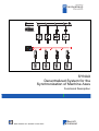
SYNAX
Decentralized System for the
Synchronization of Machine Axes
Functional Description
DOK-SYNAX*-SY*-06VRS**- FK01-EN-P
Rexroth
Indramat
About this documentation
Title
Type of documentation
Document type code
Internal file reference
SYNAX
SYNAX Decentralized System for the Synchronization of Machine Axes
Functional Description
DOK-SYNAX*-SY*-06VRS**-FK01-EN-P
• Schuber 40-06V-EN
• SY106E_F.doc
• Document number: 120-2200-B303-01 EN
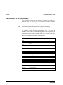
The purpose of the
documentation:
This documentation serves to
• help familiarize the user with SYNAX
• familiarize the user with how to synchronize a sequential to a master
axis
• select the applications required for the functions
Editing sequence
Copyright
Document designations of
previous editions
Status
Comments
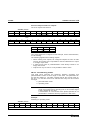
209-0061-4301-01
08.95
Version 02VRS
DOK-SYNAX*-SY*-03VRS*G-ANW1-EN-P
08.96
Version 03VRS
DOK-SYNAX*-SY*-04VRS*-FKB1-EN-P
04.97
Version 04VRS
DOK-SYNAX*-SY*-05VRS*-FKB1-EN-P
02.98
Version 05VRS
DOK-SYNAX*-SY*-06VRS*-FK01-EN-P
06.99
Version 06VRS
INDRAMAT GmbH, 1999
Copying this document, and giving it to others and the use or
communication of the contents thereof without express authority are
forbidden. Offenders are liable for the payment of damages. All rights are
reserved in the event of the grant of a patent or the registration of a utility
model or design (DIN 34-1).
Validity
Published by
All rights are reserved with respect to the content of this documentation
and the available of the product.
INDRAMAT GmbH • Bgm.-Dr.-Nebel-Str. 2 • D-97816 Lohr a. Main
Telefon 09352/40-0 • Tx 689421 • Fax 09352/40-4885
Dept. BAP (KST), ESP (STS, TI)
Note
This document is printed on paper bleached without the use of chlorine.
DOK-SYNAX*-SY*-06VRS**-FK01-EN-P
SYNAX
About this documentation
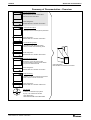
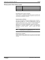
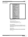
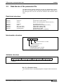
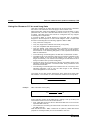
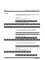
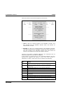
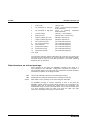
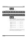
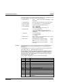
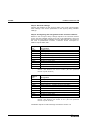
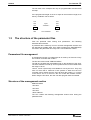
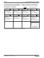
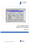
Summary of Documentation - Overview
Functional Description:
Help familiarize the user with SYNAX
and the functions of SYNAX
FK
Order designation:
DOK-SYNAX*-SY*-06VRS**-FK01-EN-P
282801
Parameter Description:
Description of the SYNAX system parameters
PA
Order designation:
DOK-SYNAX*-SY*-06VRS**-PA01-EN-P
282801
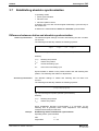
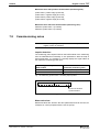
Trouble Shooting Guide:
Explanation of the diagnostics states
How to proceed when eliminating faults
WA
Order designation:
DOK-SYNAX*-SY*-06VRS**-WA01-EN-P
282801
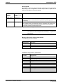
Firmware Version Notes:
Description of the new and changed
functions between SYNAX version 06VRS
and previous SYNAX 05VRS
FV
Order designation:
DOK-SYNAX*-SY*-06VRS**-FV01-EN-P
282801
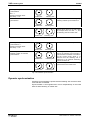
Project Planning:
Selection of units and hardware components
Basic control in cabinet construction
PR
Order designation:
DOK-SYNAX*-SY*-06VRS**-PR01-EN-P
282801
CD: SynTop
Win3 1 and
Win95&NT
7]R8ST
Collection of Windows help systems
SynTop, user interface for SYNAX
Order designation:
SWD-SYNTOP-INB-04VRS-MS-CD600
DOK-SYNAX*-SY*-06VRS**-FK01-EN-P
Order designation:
DOK-SYNAX*-SY*-06VRS**-4001-EN-P
About this documentation
SYNAX
DOK-SYNAX*-SY*-06VRS**-FK01-EN-P
Contents I
SYNAX
Contents
1 Introduction
1-1
1.1 The SYNAX solution ............................................................................................................................ 1-1
Mechanical coupling with a main shaft.......................................................................................... 1-1
Electronic coupling with SYNAX.................................................................................................... 1-2
1.2 The range of SYNAX functions ............................................................................................................ 1-4
1.3 The system components of SYNAX..................................................................................................... 1-8
1.4 SYNAX Reference List....................................................................................................................... 1-13
Referenced firmware................................................................................................................... 1-13
Supplementary documentation ................................................................................................... 1-14
1.5 Adapting SYNAX to a machine .......................................................................................................... 1-14
1.6 Safety guidelines for control units ...................................................................................................... 1-16
General information..................................................................................................................... 1-16
Protection against contact with electrical parts .......................................................................... 1-17
Protection by protective low voltage (PELV) against electrical shock......................................... 1-18
Protection against dangerous movements.................................................................................. 1-19
Protection against magnetic and electromagnetic fields during operations and mounting ......... 1-21
Protection during handling and installation.................................................................................. 1-21
Battery safety .............................................................................................................................. 1-22
2 Master axis and cam switch group
2-1
2.1 General information on the master axis ............................................................................................... 2-1
2.2 Real master axis .................................................................................................................................. 2-2
The function of the real master axis .............................................................................................. 2-2
Electronic measuring gear ............................................................................................................ 2-3
Actual value smoothing ................................................................................................................. 2-5
Monitoring master axis position..................................................................................................... 2-6
Monitoring the master axis encoder .............................................................................................. 2-7
Binary I/Os of the real master axis ................................................................................................ 2-9
Parameters for the real master axis ............................................................................................ 2-10
2.3 Virtual master axis ............................................................................................................................. 2-11
Functions of the virtual master axis............................................................................................. 2-11
Operating states.......................................................................................................................... 2-12
Basic function .............................................................................................................................. 2-13
Positioning................................................................................................................................... 2-15
Binary I/O of the virtual master axis ............................................................................................ 2-17
Parameters for operating the virtual master axis ........................................................................ 2-20
2.4 Additive master axis command value ................................................................................................ 2-21
2.5 Standard cam switches...................................................................................................................... 2-22
Binary I/Os of the standard cam switches................................................................................... 2-23
DOK-SYNAX*-SY*-06VRS**-FK01-EN-P
II Contents
SYNAX
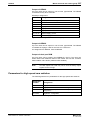
Parameters of the standard cam switch...................................................................................... 2-24
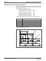
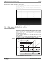
2.6 High speed standard cam switch ....................................................................................................... 2-24
Functional Principle..................................................................................................................... 2-24
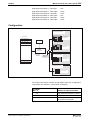
Configuration ............................................................................................................................... 2-25
Parameters for high speed cam switches ................................................................................... 2-27
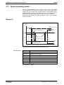
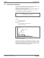
2.7 Speed operating points ...................................................................................................................... 2-28
Binary I/O .................................................................................................................................... 2-28
Parameters for the speed switching point ................................................................................... 2-29
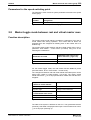
2.8 Master toggle mode between real and virtual master axes ............................................................... 2-29
Function description .................................................................................................................... 2-29
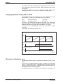
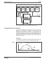
Change from real to virtual master axis ...................................................................................... 2-30
Changeover from virtual to real master axis ............................................................................... 2-34
3 Following axis
3-1
3.1 Following axes operating modes ......................................................................................................... 3-1
3.2 Synchronization.................................................................................................................................... 3-1
Gear functions ............................................................................................................................... 3-2
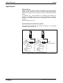
3.3 Speed synchronization......................................................................................................................... 3-5
Applications ................................................................................................................................... 3-6
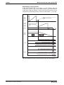
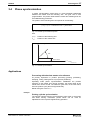
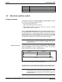
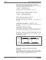
3.4 Phase synchronization......................................................................................................................... 3-7
Applications ................................................................................................................................... 3-7
Effective phase offset.................................................................................................................... 3-8
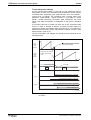
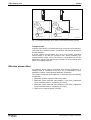
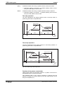
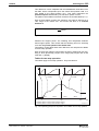
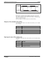
3.5 Electronic cam ................................................................................................................................... 3-12
Electronic cam operating mode................................................................................................... 3-12
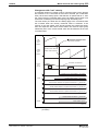
Cam with finite movement........................................................................................................... 3-13
Cam with infinite movement ........................................................................................................ 3-13
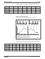
Electronic cam table.................................................................................................................... 3-16
Changing between cam profile 1 and 2....................................................................................... 3-17
Overview of electronic cam ......................................................................................................... 3-17
Changing the hub in cam mode .................................................................................................. 3-18
Changing the phase offset in cam mode .................................................................................... 3-19
Binary I/Os of the electronic cam ................................................................................................ 3-20
Parameters of the electronic cam ............................................................................................... 3-20
3.6 Electronic pattern control ................................................................................................................... 3-21
Primary function .......................................................................................................................... 3-21
Interface configuration................................................................................................................. 3-26
Pattern computer......................................................................................................................... 3-27
The structure of the electronic pattern control ............................................................................ 3-32
Monitoring the target positions .................................................................................................... 3-35
Pattern control parameters.......................................................................................................... 3-37
CLC error messages ................................................................................................................... 3-39
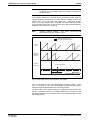
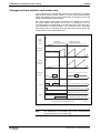
3.7 Establishing absolute synchronization ............................................................................................... 3-41
Difference between relative and absolute synchronization ......................................................... 3-41
Dynamic synchronization ............................................................................................................ 3-42
Speed adjustments during synchronization................................................................................. 3-43
Position adjustments during sychronization ................................................................................ 3-44
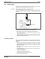
3.8 Setup mode........................................................................................................................................ 3-46
DOK-SYNAX*-SY*-06VRS**-FK01-EN-P
Contents III
SYNAX
Function principle ........................................................................................................................ 3-46
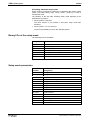
Binary I/Os of the setup mode..................................................................................................... 3-48
Setup mode parameters.............................................................................................................. 3-48
3.9 Idle ..................................................................................................................................................... 3-49
Idle speeds .................................................................................................................................. 3-50
Binary I/Os of idle mode.............................................................................................................. 3-51
Idle mode parameters ................................................................................................................. 3-51
3.10 Free auxiliary modes (special modes) ............................................................................................. 3-52
Relative setup mode ................................................................................................................... 3-52
Master-Slave mode ..................................................................................................................... 3-54
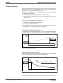
3.11 Using I/Os to control the following axis ............................................................................................ 3-56
Setting up the operating mode .................................................................................................... 3-56
Referencing ................................................................................................................................. 3-58
Drive halt ..................................................................................................................................... 3-59
Binary I/Os of the following axis .................................................................................................. 3-60
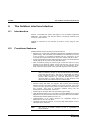
4 Internal and external I/O logic
4-1
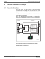
4.1 General information ............................................................................................................................. 4-1
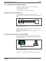
4.2 External I/O connection options ........................................................................................................... 4-2
External I/O coupling via DEA cards ............................................................................................. 4-2
Coupling the external I/O via a dual port RAM.............................................................................. 4-2
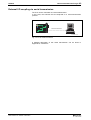
External I/O coupling via serial transmission ................................................................................ 4-3
I/O logic summary ......................................................................................................................... 4-4
4.3 Available external I/Os ......................................................................................................................... 4-4
I/Os of the DEA cards in the drives ............................................................................................... 4-5
I/Os of the DEA cards on the CLC ................................................................................................ 4-6
I/Os on the dual port RAM of the CLC-P....................................................................................... 4-7
I/Os in serial protocols................................................................................................................... 4-7
4.4 Available internal I/Os .......................................................................................................................... 4-9
Master axis inputs ....................................................................................................................... 4-10
Master axis output....................................................................................................................... 4-12
Outputs of the standard cam switch............................................................................................ 4-14
High speed cams of the master axis ........................................................................................... 4-14
Following axis inputs ................................................................................................................... 4-15
Following axis outputs................................................................................................................. 4-22
Drive cams .................................................................................................................................. 4-27
Pattern control inputs .................................................................................................................. 4-27
Pattern control outputs ................................................................................................................ 4-28
Auxiliary markers......................................................................................................................... 4-28
CLC inputs................................................................................................................................... 4-28
CLC outputs ................................................................................................................................ 4-30
R/S Flip-Flops.............................................................................................................................. 4-33
4.5 Allocating internal/external I/Os (I/O logic)......................................................................................... 4-34
Direct allocations......................................................................................................................... 4-34
AND/OR links .............................................................................................................................. 4-34
Using markers ............................................................................................................................. 4-35
The allocation list......................................................................................................................... 4-35
DOK-SYNAX*-SY*-06VRS**-FK01-EN-P
IV Contents
SYNAX
4.6 I/O logic parameters........................................................................................................................... 4-37
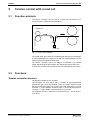
5 Tension control with a load cell
5-1
5.1 Function principle................................................................................................................................. 5-1
5.2 Functions.............................................................................................................................................. 5-1
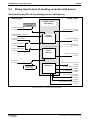
Tension controller structure........................................................................................................... 5-1
Monitoring and diagnosis of the tension control............................................................................ 5-3
Controlling several axes................................................................................................................ 5-3
5.3 Binary I/Os of the tension control......................................................................................................... 5-3
Overview binary I/Os of the tension control................................................................................... 5-3
Binary inputs of the tension control ............................................................................................... 5-4
Binary outputs of the tension control............................................................................................. 5-5
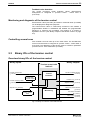
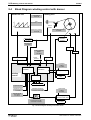
5.4 Block diagram ...................................................................................................................................... 5-6
Tension controller affecting parameter "Gear ratio - fine adjustment" .......................................... 5-6
Tension controller affecting parameter "Master axis gear - output revolutions"............................ 5-7
5.5 Tension control parameters ................................................................................................................. 5-8
6 Dancer Control
6-1
6.1 Function principle................................................................................................................................. 6-1
6.2 Functions.............................................................................................................................................. 6-1
Dancer control ............................................................................................................................... 6-1
Monitoring and diagnoses of the dancer control ........................................................................... 6-3
Controlling several axes................................................................................................................ 6-3
6.3 Binary I/Os of the dancer control.......................................................................................................... 6-4
Overview binary I/Os of the dancer control ................................................................................... 6-4
Binary inputs of the dancer control................................................................................................ 6-4
Binary outputs of the dancer control.............................................................................................. 6-5
6.4 Block Diagram...................................................................................................................................... 6-6
6.5 Parameter overview of the dancer control ........................................................................................... 6-7
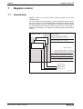
7 Register control
7-1
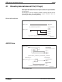
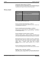
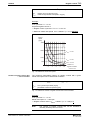
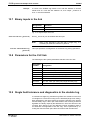
7.1 Introduction .......................................................................................................................................... 7-1
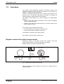
7.2 Functions.............................................................................................................................................. 7-2
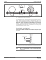
Register control with position measurement ................................................................................. 7-2
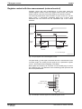
Register control with time measurement (external control)........................................................... 7-4
Correction processes .................................................................................................................... 7-5
Correcting several axes ................................................................................................................ 7-6
General definition of terms ............................................................................................................ 7-6
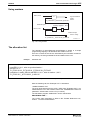
7.3 Binary I/Os of the register control......................................................................................................... 7-8
Binary inputs.................................................................................................................................. 7-8
Binary outputs ............................................................................................................................... 7-9
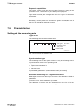
7.4 Insetting control.................................................................................................................................. 7-10
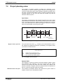
7.5 Project planning notes........................................................................................................................ 7-12
7.6 Parametrization .................................................................................................................................. 7-14
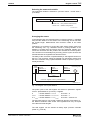
Settings at the measuring axis .................................................................................................... 7-14
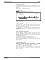
Settings at the controlled axis ..................................................................................................... 7-20
Direct correction with position measurement .............................................................................. 7-24
DOK-SYNAX*-SY*-06VRS**-FK01-EN-P
Contents V
SYNAX
Indirect correction with position measurement............................................................................ 7-29
Direct correction with time measurement.................................................................................... 7-30
Block diagram ............................................................................................................................. 7-33
7.7 Parameter overview ........................................................................................................................... 7-36
7.8 Commissioning notes......................................................................................................................... 7-37
8 Winding Control without sensors
8-1
8.1 Function principle................................................................................................................................. 8-1
8.2 Functions.............................................................................................................................................. 8-2
Winding up and down.................................................................................................................... 8-2
Calculating diameters.................................................................................................................... 8-2
Tensing the web............................................................................................................................ 8-3
Switching from operating to standstill web tension ....................................................................... 8-4
Reference axis of the winding drive .............................................................................................. 8-4
Changing rolls ............................................................................................................................... 8-4
8.3 Binary I/Os of the winding control ........................................................................................................ 8-5
Binary inputs winding control without sensors............................................................................... 8-5
Binary outputs winding control without sensors ............................................................................ 8-5
8.4 Parametrization .................................................................................................................................... 8-6
Presets and limit values ................................................................................................................ 8-7
Block diagram for winding control ................................................................................................. 8-8
8.5 Commissioning the winding control ..................................................................................................... 8-9
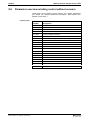
8.6 Parameter overview winding control without sensors ........................................................................ 8-11
9 Winding control with dancer
9-1
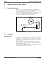
9.1 Function principle................................................................................................................................. 9-1
9.2 Functions.............................................................................................................................................. 9-1
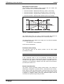
Dancer control ............................................................................................................................... 9-1
Diameter calculation...................................................................................................................... 9-3
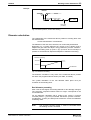
Monitoring and diagnoses of the winding control with dancer....................................................... 9-4
Rotational direction of the winding axis......................................................................................... 9-4
Reference axis of the winder......................................................................................................... 9-5
9.3 Binary input/output of winding controller with dancer........................................................................... 9-6
Overview binary I/Os of the winding control with dancer............................................................... 9-6
Binary inputs of the winding control with dancer ........................................................................... 9-7
Binary outputs of the winding control with dancer......................................................................... 9-8
9.4 Block Diagram winding control with dancer ....................................................................................... 9-10
9.5 Parameter overview of winding control with dancer........................................................................... 9-11
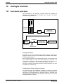
10 Analogue channels
10-1
10.1 Functional principles ........................................................................................................................ 10-1
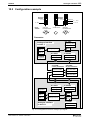
10.2 Configuration example ..................................................................................................................... 10-3
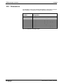
10.3 Parameters ...................................................................................................................................... 10-4
11 Jogging function
11-1
11.1 Operating principle of the jogging inputs.......................................................................................... 11-1
DOK-SYNAX*-SY*-06VRS**-FK01-EN-P
VI Contents
SYNAX
Via jog inputs affected parameters ............................................................................................. 11-1
Activate jogging (following axis) .................................................................................................. 11-2
Jogging rate................................................................................................................................. 11-2
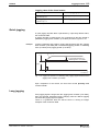
Quick jogging .............................................................................................................................. 11-3
Long jogging................................................................................................................................ 11-3
Jog limits ..................................................................................................................................... 11-4
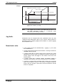
Some basic rules......................................................................................................................... 11-4
11.2 Examples ......................................................................................................................................... 11-5
Jogging fine adjustment gearbox transmission (A-0-0060)......................................................... 11-5
Jogging the "position command offset" (A-0-0004)..................................................................... 11-5
Jogging the master drive gear output revolutions (A-0-0126) ..................................................... 11-6
Jogging the master axis speed (C-0-0006) ................................................................................. 11-6
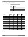
11.3 Binary I/Os of the jogging function ................................................................................................... 11-7
11.4 Jogging function parameters............................................................................................................ 11-8
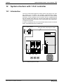
12 System structure with 1 CLC controller
12-1
12.1 Introduction ...................................................................................................................................... 12-1
12.2 Drive administration ......................................................................................................................... 12-2
Projected drives .......................................................................................................................... 12-2
Deactivating a defective drive ..................................................................................................... 12-2
Checking the drive configuration................................................................................................. 12-3
12.3 Parameters ...................................................................................................................................... 12-3
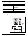
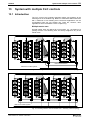
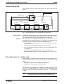
13 System with multiple CLC controls
13-1
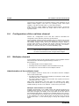
13.1 Introduction ...................................................................................................................................... 13-1
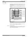
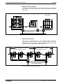
13.2 The CLC link .................................................................................................................................... 13-3
Hardware configuration ............................................................................................................... 13-3
CLC link with single ring.............................................................................................................. 13-4
CLC link with double ring............................................................................................................. 13-5
13.3 Configuring the link participants....................................................................................................... 13-6
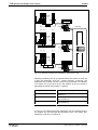
13.4 Single - double ring configuration..................................................................................................... 13-7
13.5 Master axis configuration ................................................................................................................. 13-7
13.6 Binary outputs in the link.................................................................................................................. 13-9
13.7 Binary inputs in the link .................................................................................................................. 13-10
13.8 Parameters for the CLC link........................................................................................................... 13-10
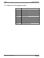
13.9 Single fault tolerance and diagnostics in the double ring............................................................... 13-10
Error in the primary ring............................................................................................................. 13-12
Error in the secondary ring........................................................................................................ 13-13
Double LWL break .................................................................................................................... 13-14
Reconfiguration to a double ring ............................................................................................... 13-14
13.10 Additive master axis command value in the CLC link .................................................................. 13-15
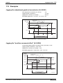
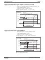
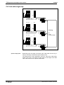
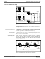
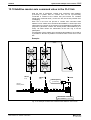
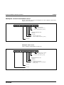
13.11 Configuration Examples............................................................................................................... 13-16
Machine with modular construction........................................................................................... 13-16
Rotary printer with two folding units .......................................................................................... 13-17
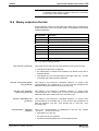
14 Glossary
14-1
DOK-SYNAX*-SY*-06VRS**-FK01-EN-P
SYNAX
15 Index
Appendix A: SynTop
Appendix B: Interfaces
Appendix C: Terminal
Directory of Customer Service Locations
DOK-SYNAX*-SY*-06VRS**-FK01-EN-P
Contents VII
15-1
VIII Contents
SYNAX
DOK-SYNAX*-SY*-06VRS**-FK01-EN-P
Introduction 1-1
SYNAX
1
Introduction
1.1
The SYNAX solution
Up until recently, the sychronization of axes of motion in such machinery
as printing or textile machines has been realized with a mechanical
longitudinal shaft and a variety of gears. However the constantly rising
demands for greater precision and productivity, as well as reductions in
cost, frequently cannot be satisfied with these concepts.
SYNAX, a decentralized system, offers the optimum technical and
economic solution. The master axis and the following axis are hereby no
longer mechanically but rather electronically coupled.
It is also possible, with SYNAX, to implement auxiliary and feed axes in
the most ideal way.
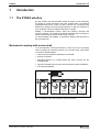
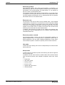
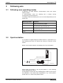
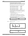
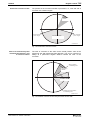
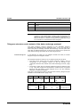
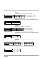
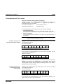
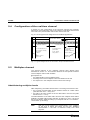
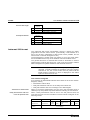
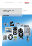
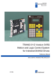
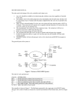
Mechanical coupling with a main shaft
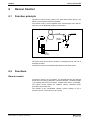
In a conventionally constructed machine, a main drive runs all printing
units or cylinders of a printing machine over one main shaft. This results
in a series of disadvantages:
• large-scale and expensive gearboxes are needed,
• precision is limited,
• disturbing torques of a cylinder affect the entire machine via the
machine shaft,
• spurious oscillations as a result of low mechanical natural oscillations
• and very little flexibility.
feeder
printing
unit 1
printing
unit 2
rotating
press
folder
SY6FB001.FH7
Fig. 1-1: Printing machine with main drive and one main shaft
DOK-SYNAX*-SY*-06VRS**-FK01-EN-P
1-2 Introduction
SYNAX
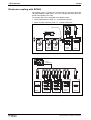
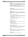
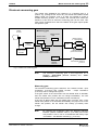
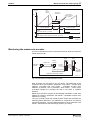
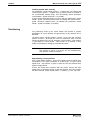
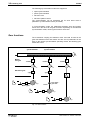
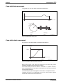
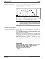
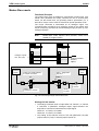
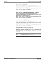
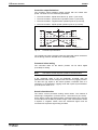
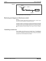
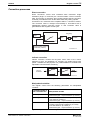
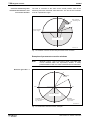
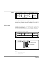
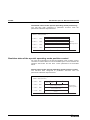
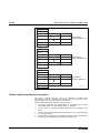
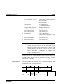
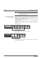
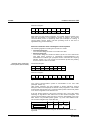
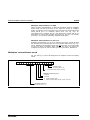
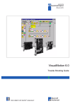
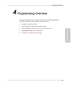
Electronic coupling with SYNAX
The printing units or cylinders are coupled with an electronic shaft and
individual intelligent digital drives. The CLC controller board produces the
master axis signals in this case.
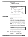
The printing units can be equipped in two different ways:
• with a partial electronic shaft, i.e., a real master axis and
• with a complete electronic shaft, i.e., a virtual master axis.
angle encoder
feeder
printing
unit 1
printing
unit 2
rotating
press
folder
SY6FB002.FH7
Fig. 1-2: A printing machine partially equipped with individual drives
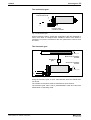
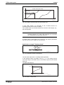
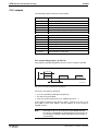
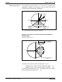
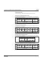
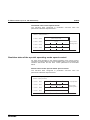
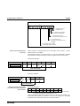
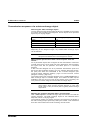
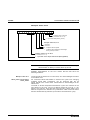
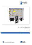
virtual
master axis
feeder
printing
unit 1
printing
unit 2
rotating
press
folder
SY6FB003.FH7
Fig. 1-3: A printing machine completely equipped with single drives
DOK-SYNAX*-SY*-06VRS**-FK01-EN-P
Introduction 1-3
SYNAX
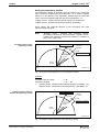
The decisive advantages of this
solution:
• Costs are reduced because numerous mechanical parts have been
eliminated.
• Higher precision and greater speed.
• Extreme flexibility.
• Energy consumption significantly reduced.
• No reactions from parasitic inductions such as cylinder bounce and
folding blade.
• Expansion is no problem because of the modular construction.
• Potential savings in costs as machine components are modular.
• Individual printing units or cylinders can be switched on or off with
great flexibility.
• A high level of synchronization precision of up to just under 0.005°, a
high degree of synchronous operation with no lag error as well as
drive-internal position control with a cycle time of 0.25 ms.
• No reactions of the machine to the disturbing torque of a cylinder.
• Practically no spurious oscillations from high mechanical natural
frequencies.
• Minute settings of whole-number gearbox translations equal to from
1:65 000 to 65 000 : 1, speed ratios, longitudinal registers and so on.
• Printing units can be commissioned and tested individually.
• The modular construction makes it possible to interconnect up to 40
drives.
• Absolute angle encoder with a resolution of 1/2 000 000th revolution
for the master axis.
• Simple parametrization makes it possible to easily adapt various
machines and controllers.
• A comfortable diagnosis of all operating states as well as a rapid
commission in the event of a problem.
• A broad spectrum of digital electronics for the drive, of highly dynamic
motors, of interfaces for specific applications and of additional
components.
• SYNAX solution for auxiliary and feed drives.
DOK-SYNAX*-SY*-06VRS**-FK01-EN-P
1-4 Introduction
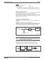
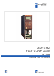
1.2
SYNAX
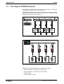
The range of SYNAX functions
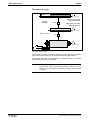
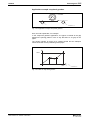
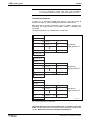
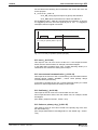
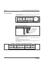
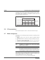
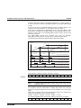
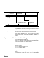
Using SYNAX, it is possible to build machines which have no mechanical
main shafts, couplings, drives, cams and so on.
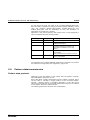
Digital intelligent drives replace the mechanical gears, a fiber optics cable
replaces the mechanical line shaft, while the CLC controller board
replaces the function of the master axis.
SY6FB004.FH7
Fig. 1-4: Conventional machine construction with a mechanical line shaft
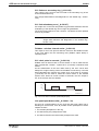
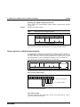
SY6FB005.FH7
Fig.1-5: Machine construction with electronic line shaft and single digital drives
SYNAX offers the following functions to replace the gearbox:
• electronic gearbox - with phase synchronization
• electronic gearbox - with velocity synchronization
• electronic cam
• electronic pattern control
DOK-SYNAX*-SY*-06VRS**-FK01-EN-P
Introduction 1-5
SYNAX
Electronic gearbox
The electronic gearbox with phase synchronization is equivalent to a
differential gear with servo motor capable of being coupled. The gearbox
transmission can be parametrized, the offset phase, i.e., the position of
the servo motor, can be altered online.
The electronic gearbox with velocity synchronization, on the other hand,
is equivalent to a PIV gear with servo motor for the transmission ratio.
The base gearbox transmission can be parametrized and the gearbox
transmission factor can be altered online.
Electronic cam
The electronic cam can be used in many versatile ways. In the simplest
of applications, it reproduces a mechanical cam which translates rotating
motion into linear motion. The geometry of the curve is stored in the drive
in the form of a supporting point table. The phase offset of the cam with
respect to the master axis, the offset of the linear axis as well as the
stretching of the cam itself can all be altered online.
In addition, almost all laws of motion for the master and following axes
can be preset. Areas of applications are, for example, rotay knives and
intermittent feed units.
Electronic pattern controls
The electronic pattern controls can only be mechanically realized in a
highly simplified version. In simple terms, it represents a basic cam in
which segments of the cam were modified independent of each other.
These electronic pattern controls are primarily used in textile machines.
Idle mode
In idle mode, the following axis is driven independently of the ELS master
with a preset set.
Setup mode
In setup mode it is possible to position the following axis without regard to
the ELS master axis.
In addition to these drive functions, SYNAX offers other functions which
have, up until the present, been realized in separate control units. These
are:
• master axis
• cam switch group
• winding control
• tension control
• register and inset control
• communications
DOK-SYNAX*-SY*-06VRS**-FK01-EN-P
1-6 Introduction
SYNAX
Master axis
The function of the ELS master generally produces the position of the
master axis in terms of the virtual master axis for which, as is the case
with conventional drives, acceleraiton, speed and position can be preset.
Alternatively, a high-resolution single-turn absolute encoder can
aditionally be mounted to support a real master axis.
The function of the master axis also makes a series of status signals
available, such as speed switching points, standstill, errors and so on.
Cam switch group
Using the cam switch group means various switches can be turned on
and off dependent on the angular position of the ELS master axis.
Winding controls
The winding function for unwinding and winding up with central driven
winders uses the master axis velocity and the winding velocity on the
core (the actual speed of the winding motor) to calculate the current reel
diameter.
In the design as winding without sensor
• this information is used to specify the torque of the winding drive via
the lever bar in such a way that the web is winded up or down with a
controlled tension.
In the case of a winding control with dancer control
• the tension is enforced via a dancer. The position of the dancer is
controlled by the dancer controller.
Tension control
Tension control with load cell
controls dependent of the measured value of a load cell the tension to
the desired command value.
In the case of a dancer control
• tension is enforced via a dancer. The position of the dancer is
controlled by the dancer control.
Register and insetter control
The register and insetter control corrects any deviations between a
register marker and the printing cylinder position and, for example, the
position of a printing cylinder in terms of a desired variable.
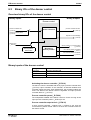
I/O logic
The I/O logic implemented can be programmed. It can link external
binary signals with such internal control and status signals as operating
mode, ready signals, error messages and so on.
Analogue inputs
It is possible to set some parameters via analogue inputs.
DOK-SYNAX*-SY*-06VRS**-FK01-EN-P
Introduction 1-7
SYNAX
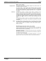
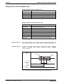
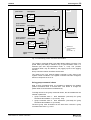
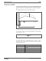
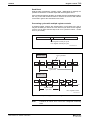
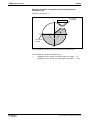
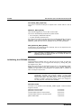
Communication
Various interfaces and protocols are available for the communication with
higher-ranking control units, e.g., PCs, PLCs or master computers.
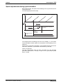
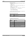
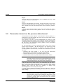
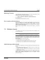
CLC link
In complex machines, several motional controls are combined together in
one control link (CLC link).
fold A
fold. B
cross communication
data bus to master system
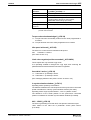
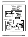
Fig. 1-6: CLC link in a newspaper printing machine
Each CLC is capable of calculating its own master axis position. Each
drive in the link can be assigned to any master axis. The combining of
the CLC controls uses the CLC plug-in card DAQ. The DAQ cards for the
cross communications between the CLC controls are linked by a fiber
optic cable link ring thus creating the CLC link.
Coupling via a doubled fiber optic cable ring ensures a one-error
tolerance within the CLC link. The system tolerates the failure of a single
motion control and the damaging of a fiber optic line between the DAQ
modules.
DOK-SYNAX*-SY*-06VRS**-FK01-EN-P
1-8 Introduction
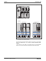
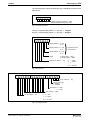
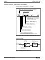
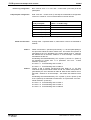
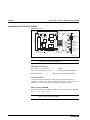
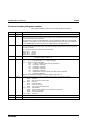
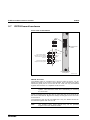
The system components of SYNAX
SYNAX systems consist of up to 40 digital intelligent drives, a CLC-D or
CLC-P plug-in controller board, a fiber optics cable connection between
these components, which meets SERCOS interface standards, as well
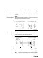
as a number of optional plug-in modules for the digital intelligent drives.
The digital intelligent drives are made up of drive controllers and their
matching motors.
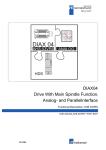
Drive controller
As drive amplifier, it is possible to use the DIAX03, DIAX04 or
ECODRIVE family.
The program of the unit includes
• compact controllers up to 93 kW to supply power to single motors and
• modular units up to 35 kW for drive groups.
DIAX03
L1
L2
L3
ECODRIVE
L1
L3
L2
A1
X5
A2
A3
N L
B1 B2 L- L+
220 V
Steuerspannung
Aux.
220 V
Steuerspannung
Aux.
X6
BR
TM+
TM-
A2
N L K B1 B2 X10
A3
Motor
•
•
•
•
Netz/Mains
A1
Motor
Netz/Mains
U5
S1
H1
Barcode
Typenschild
11121314 1516 1718 5 6 7 8
1 2 3 4 5 6 7 8 9 1 2 3 4
U1
U3
U2
U4
H2
U5
S2
S1
1
X9
H1
U1
6
U3
1
X8
X2
7
1
1
S1
S3
S2
1
8
3
3
8
1
2
2
7
0
7
9
6
0
5
9
X7
Barcode
H1
H2
10
X3
1
X4
S2
4
4
5
6
1.3
SYNAX
1
5 6 7 8
1 2 3 4
X9
6
1
U2
L+
X8
U4
DIGITAL COMPACT CONTROLLER DKR
X2
7
L-
1
1
L1
A1
L2
A2
XE1 L3
A3
DANG
XE2
High oltage.
Danger of electrical shock.
Do not touch electrical connections
for
5 minutes after switching
Read and follow
Instructions for Electrical Drives"
manual,
DOK-GENERL-DRIVE******-SVS...
DKC**.3
X7
10
X3
1
DIGITAL COMPACT CONTROLLER DKR
X4
DKR 3.1
DKR 2.1
SY6FB007.FH7
Fig. 1-7: Compact controller examples
DOK-SYNAX*-SY*-06VRS**-FK01-EN-P
Introduction 1-9
SYNAX
DIAX03
DDS02.2
DDS02.2
DDS03.2
DIAX04
single axis unit
DANG
High V oltage.
Danger of electrical shock.
Do not touch electrical connec tions
fo
5 minutes after switching power
Read and follow "Safety
Instructions for Electrical Drives"
manual,
DOK-GENERL-DRIVE******-SVS...
U
V
DANG
High V oltage.
Danger of electrical shock.
Do not touch electrical connec tions
fo
5 minutes after switching power
Read and follow "Safety
Instructions for Electrical Drives"
manual,
DOK-GENERL-DRIVE******-SVS...
DANGE
High V oltage.
Danger of electrical shock.
Do not touch electrical connec tions
for
5 minutes after switching power
Read and follow "Safety
Instructions for Electrical Drives"
manual,
DOK-GENERL-DRIVE******-SVS...
double axis unit
DANGE
DANG
High V oltage.
Danger of electrical shock.
Do not touch electrical connec tions
for
5 minutes after switching power
Read and follow "Safety
Instructions for Electrical Drives"
manual,
DOK-GENERL-DRIVE******-SVS...
W
High V oltage.
Danger of electrical shock.
Do not touch electrical connec tions
fo
5 minutes after switching power
Read and follow "Safety
Instructions for Electrical Drives"
manual,
DOK-GENERL-DRIVE******-SVS...
U
HDS 02.2
HDS 03.2
HDS 04.2
V
DANGE
High V oltage.
Danger of electrical shock.
Do not touch electrical connec tions
for
5 minutes after switching power
Read and follow "Safety
Instructions for Electrical Drives"
manual,
DOK-GENERL-DRIVE******-SVS...
DANGE
High V oltage.
Danger of electrical shock.
Do not touch electrical connec tions
for
5 minutes after switching power
Read and follow "Safety
Instructions for Electrical Drives"
manual,
DOK-GENERL-DRIVE******-SVS...
W
HDD02.2
SY6FB169.FH7
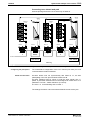
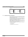
Fig. 1-8: Modular drive controller examples
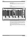
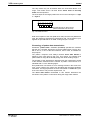
The single axis unit family DIAX04 (HDS) and all units of the DIAX03
family are outfitted with 1 to 3 slots for optional additional plug-in
modules.
In the double axis units HDD of the DIAX04 family and all ECODRIVE
families, the slots are filled with the SERCOS interface DSS module.
DOK-SYNAX*-SY*-06VRS**-FK01-EN-P
1-10 Introduction
SYNAX
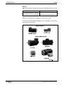
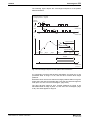
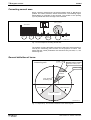
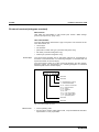
Motors
The motor program includes mounting and assembly motors up to 93
kW.
Mounting motor
Kit motors
Synchronous motors 0.15 - 122 Nm
Asynchronous motors up to 93 kW
Asynchronous motors up to 55 kW
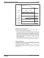
Fig. 1-9: Power range of rotary motors
Either air or liquid cooling is available for almost every motor.
All rotary motors MKD/MKE, MDD/MHD, 2AD, 1MB, MBW, LAF and LSF
linear motors can be used.
Fig. 1-10:
Motor series
DOK-SYNAX*-SY*-06VRS**-FK01-EN-P
Introduction 1-11
SYNAX
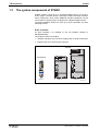
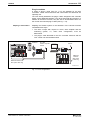
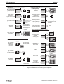
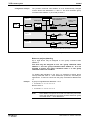
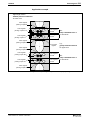
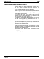
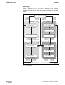
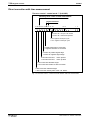
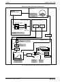
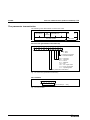
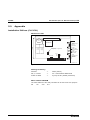
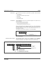
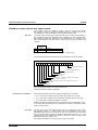
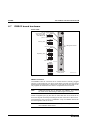
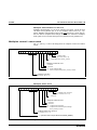
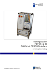
Plug-in modules
A series of plug-in cards (see Fig. 1-12) are available for all drive
controllers. These ensure that drive and control tasks and demands are
optimally met.
The CLC directly addresses the plug-in cards, assigned to the controller
board, via the SERCOS interface. The drives thus fulfill two functions. In
addition to their drive function, they are also a decentralized carrier for
the control unit oriented plug-in cards (see Fig. 1-12).
Adapting the SYNAX system to the hardware of the relevant machine
necessitates two steps:
Adapting to the hardware
• The drive concept with respect to motor, drive amplifier and the
measuring system, i.e., basic drive configuration, must be
determined.
• The plug-in cards allocated to the CLC controller functions and the
CLC control unit must be determined.
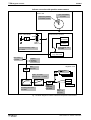
CCD box
U
U
U
U
H
POWE
PC, SPS
master computer
service
Service
X
+24
0
CLC-P
CLC-D
SERCOS
interface
fiber optics
cable ring
SERCOS interface
fiber optics cable ring
SY6FB009.FH7
Fig. 1-11: CLC configurations
DOK-SYNAX*-SY*-06VRS**-FK01-EN-P
1-12 Introduction
SYNAX
Plug-in modules functionally allocated
to the CLC control unit:
Plug-in modules functionally allocated
to the drives:
DLF high-resolution
position interface
DLF
Way
DEA digital input
and output
interface
DEA04/
DEA08
GDS 1.1
DEF position
interface for
square-wave signals
DZF high-resolution
gear-tooth encoder
interface
DEF
Way
DZF
gear-tooth encoder
rack-and-pinion
encoder
DFF high-resolution
master axis
encoder interface
DFF
analogue interface
with position
value output DAE
(only ELS5)
DAE
master axis position
SSI-output interface
DSA
+/- 10V analogue
incremental encoder
emulation
fiber optic cable
SERCOS
interface
travel limit switch
referencing switch
measuring input
DSS
Plug-in modules allocated to the CLC-D
in the CCD box
e.g. SPS
drive cam
DEA digital input
and output
interface
SSI
DEA05/
DEA06
DAQ
CLC link and/or
ARCNET
coupling card
DAQ
e. g. SPS
Interface module allocated to either the drive
or the CLC control unit:
high-resolution
digital servo
feedback
interface
X4
motor feedback
with MDD, MKD
e. g. SPS
INTERBUS-S
slave circuit
DBS
e. g. SPS
Profibus
slave circuit
X4
high-resolution
master axis
encoder interface
e. g. SPS
DeviceNet
slave circuit
EnDat/SSI
encoder
interface
DPF
GDS 1.1
DCF
EnDat
DAG
e. g. SPS
SSI
Way
SSI
motor feedback
or master axis
encoder
DEA digital
input and
output interface
DEA
28...30
SY6FB142.FH7
Fig. 1-12: Allocation by function of the plug-in cards to the drives and the CLC
plug-in controller board in a SYNAX systems configuration.
DOK-SYNAX*-SY*-06VRS**-FK01-EN-P
Introduction 1-13
SYNAX
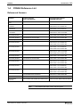
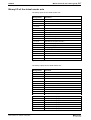
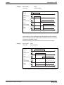
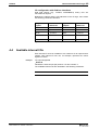
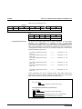
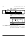
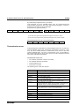
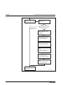
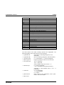
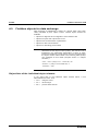
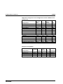
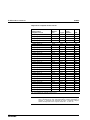
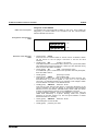
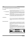
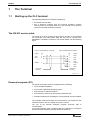
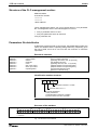
1.4
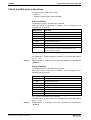
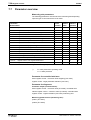
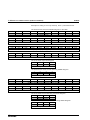
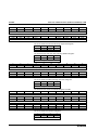
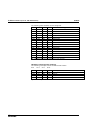
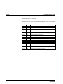
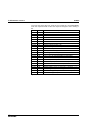
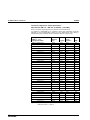
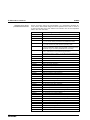
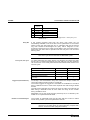
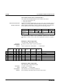
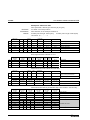
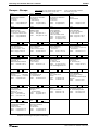
SYNAX Reference List
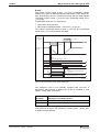
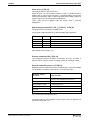
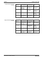
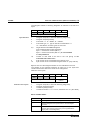
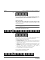
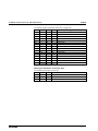
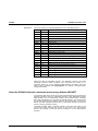
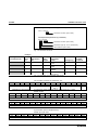
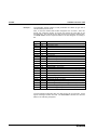
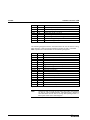
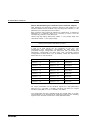
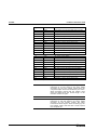
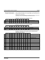
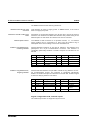
Referenced firmware
Product:
Product firmware
(order designation):
Printed board firmware
(EPROM labelling):
CLC-P / CLC-D &
CCD
FWA-CLC*DP-SY*-06VRS-MS
FWC-CLC*DP-SY*-06VRS-MS
CLC-D & CCD
+ Profibus
FWA-CLC*DP-SP1-06VRS-MS
FWC-CLC*DP-SY*-06VRS-MS
FWC-DPF5.2-CP2-03VRS-NN
CLC-D & CCD
+ Interbus-S
FWA-CLC*DP-SS1-06VRS-MS
FWC-CLC*DP-SY*-06VRS-MS
FWC-DBS3.1-CI1-02VRS-NN
CLC-D & CCD
+ DeviceNet
FWA-CLC*DP-SD1-06VRS-MS
FWC-CLC*DP-SY*-06VRS-MS
FWC-DCF01*-CD1-01VRS-NN
CLC-D &
drive family DIAX03
FWA-DIAX03-SY1-06VRS-MS
FWC-CLC*DP-SY*-06VRS-MS
FWC-DSM2.3-ELS-05VRS-MS
Drive family DIAX03
FWA-DIAX03-ELS-04VRS-MS
FWC-DSM2.3-ELS-04VRS-MS
Drive family DIAX03
FWA-DIAX03-ELS-05VRS-MS
FWC-DSM2.3-ELS-05VRS-MS
CLC-D & Profibus
drive family DIAX03
FWA-DIAX03-SP1-06VRS-MS
FWC-CLC*DP-SY*-06VRS-MS
FWC-DPF5.2-CP2-03VRS-NN
FWC-DSM2.3-ELS-05VRS-MS
CLC-D & Interbus
drive family DIAX03
FWA-DIAX03-SS1-06VRS-MS
FWC-CLC*DP-SY*-06VRS-MS
FWC-DBS3.1-CI1-02VRS-NN
FWC-DSM2.3-ELS-05VRS-MS
CLC-D & DeviceNet
drive family DIAX03
FWA-DIAX03-SD1-06VRS-MS
FWC-CLC*DP-SY*-06VRS-MS
FWC-DCF01*-CD1-01VRS-NN
FWC-DSM2.3-ELS-05VRS-MS
CLC-D &
drive family DIAX04
FWA-DIAX04-SY1-06VRS-MS
FWC-CLC*DP-SY*-06VRS-MS
FWC-HSM1.1-ELS-05VRS-MS
Drive family DIAX04
FWA-DIAX04-ELS-05VRS-MS
FWC-HSM1.1-ELS-05VRS-MS
CLC-D & Profibus
drive family DIAX04
FWA-DIAX04-SP1-06VRS-MS
FWC-CLC*DP-SY*-06VRS-MS
FWC-DPF5.2-CP2-03VRS-NN
FWC-HSM1.1-ELS-05VRS-MS
CLC-D & Interbus
drive family DIAX04
FWA-DIAX04-SS1-06VRS-MS
FWC-CLC*DP-SY*-06VRS-MS
FWC-DBS3.1-CI1-02VRS-NN
FWC-HSM1.1-ELS-05VRS-MS
CLC-D & DeviceNet
drive family DIAX04
FWA-DIAX04-SD1-06VRS-MS
FWC-CLC*DP-SY*-06VRS-MS
FWC-DCF01*-CD1-01VRS-NN
FWC-HSM1.1-ELS-05VRS-MS
Ecodrive
FWA-ECODRV-SSE-02VRS-MS
FWA-ECODRV-SSE-03VRS-MS
FWC-DKC2.1-SSE-02VRS-MS
FWC-DKC2.1-SSE-03VRS-MS
Ecodrive03
FWA-ECODR3-SGP-01VRS-MS
FWC-ESM2.1-SGP-01VRS-MS
User interface
SYNTOP
SWA-SYNTOP-INB-04VRS-MS-CD600-COPY
SWD-SYNTOP-INB-04VRS-MS-CD600
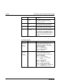
Fig. 1-13: Referenced firmware
Note:
DOK-SYNAX*-SY*-06VRS**-FK01-EN-P
The software with suffix -COPY may be copied.
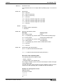
1-14 Introduction
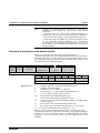
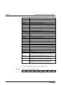
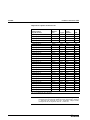
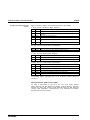
SYNAX
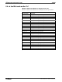
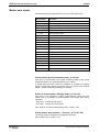
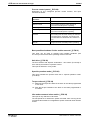
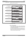
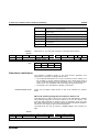
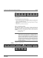
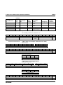
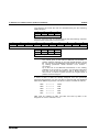
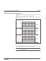
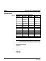
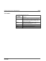
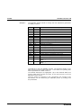
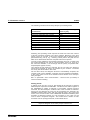
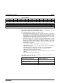
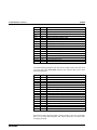
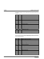
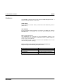
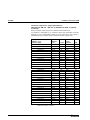
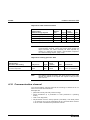
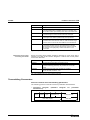
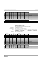
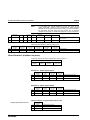
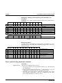
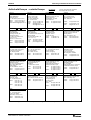
Supplementary documentation
Order text:
Title:
DOK-SYNAX*-SY*-06VRS**-FK01-EN-P
SYNAX - Functional Description
DOK-SYNAX*-SY*-06VRS**-PA01-EN-P
SYNAX - Parameter Description
DOK-SYNAX*-SY*-06VRS**-PR01-EN-P
SYNAX - Project Planning
DOK-SYNAX*-SY*-06VRS**-WA01-EN-P
SYNAX - Trouble Shooting Guide
DOK-SYNAX*-SY*-06VRS**-FV01-EN-P
SYNAX - Version notes
DOK-SYNAX*-SY*-06VRS**-4001-EN-P
SYNAX - Schuber 40-06V
SWD-SYNTOP-INB-04VRS-MS-D0600
General Support for SYNAX - Version 06VRS
DOK-DIAX03-ELS-05VRS**-50M1-EN-P
DIAX03 - Schuber 50-05V
DOK-DIAX04-ELS-05VRS**-60M1-EN-P
DIAX04 - Schuber 60-05V
DOK-ECODRV-SSE-03VRS**-57M1-EN-P
ECODRIVE - Schuber 57-03V
DOK-ECODR3-SGP-01VRS**-7201-EN-P
ECODRIVE03 - Schuber 72-01V
Fig. 1-14: Supplementary documentation
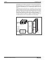
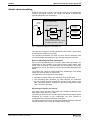
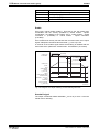
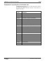
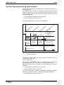
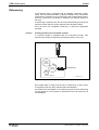
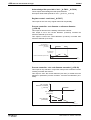
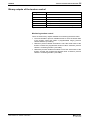
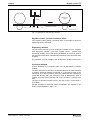
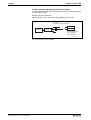
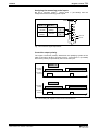
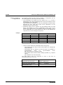
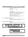
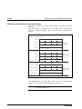
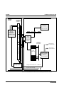
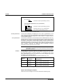
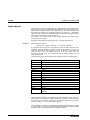
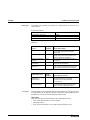
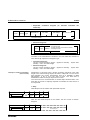
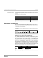
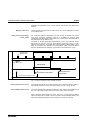
1.5
Adapting SYNAX to a machine
The hardware adaptation of SYNAX to a specific machine is achieved
with the selection of the corresponding motor/drive combination, in
particular with the already described plug-in cards.
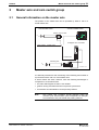
DDS
DDS
DDS
control signals
from and
to the CLC
DFF
CLC-D
rotating
press
DEA
folder
SY6FB010.FH7
Fig. 1-15: Applications example of Fig. 1.2
DOK-SYNAX*-SY*-06VRS**-FK01-EN-P
Introduction 1-15
SYNAX
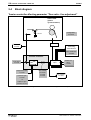
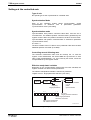
All adaptation of the software is done almost exclusively with parameters.
Axis-overreaching C and axis-related A, S and P parameters are
available for this purpose. The CLC controller board centrally takes care
of a conform parametrization of the entire SYNAX system (CLC and
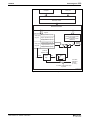
drives).
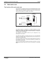
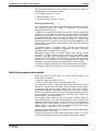
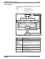
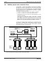
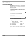
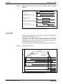
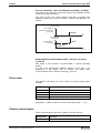
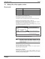
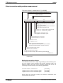
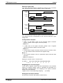
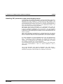
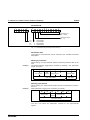
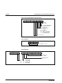
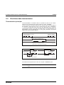
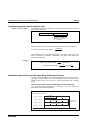
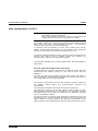
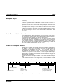
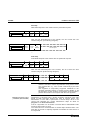
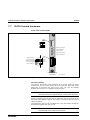
The individual axes and functions are controlled via binary inputs and
outputs. With the aid of the I/O logic, these internal input and output
signals are linked to external inputs and outputs. External I/Os are the
DEA plug-in cards with 15 inputs and 16 outputs each, as well as
memory in the dual port ram of the CLC-P or the CLC-D which can be
accessed via a serial protocol such as Siemens 3965R or ARCNET.
The logic program is created in a textfile. It is loaded onto the CLC
controller board in the form of a parameter list once it is compiled.
external I/O
internal I/O
...
input
signals
15I/16O
DEA 4
I/O
logic
parallel
or serial
communications
interface
output
signals
PC-Bus
or
RS 232
or
ARCNet
drive ...
drive 2
drive 1
master axis
SY6FB011.FH7
Fig. 1-16: I/O logic
DOK-SYNAX*-SY*-06VRS**-FK01-EN-P
1-16 Introduction
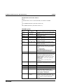
1.6
SYNAX
Safety guidelines for control units
General information
These instructions must be read and understood before the equipment
is used to minimize the risk of personel injury and / or property damage.
Follow these safety instructions at all times.
If the product is resold, rented and / or otherwise transferred or passed
on to others, these safety instructions must accompany it.
WARNUNG
Improper use of this equipment, failure to follow the
attached safety instructions, or tampering with the
product, including disabling of safety device, may
result in personal injury, severe electrical shock,
death, or property damage.
• Indramat is not liable for damages resulting from failure to observe
the warnings given in these instructions.
• Operating, maintenance and safety instruction in the appropriate
language must be ordered and received before initial start-up, if the
instructions in the language provided are not understood perfectly.
• Proper and correct transport, storage, assembly and installation as
well as care in operation and maintenance are prerequisites for
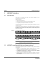
optimal and safe operation of this equipment.
• Trained and qualified personnel:
Only trained and qualified personnel may work on this equipment or in
its vicinity. Personnel is qualified if they have sufficent knowledge of
the assembly, installation, and operation of the product as well as of
all warnings and precautionary measures noted in these instructions.
Furthermore, they should be trained, instructed and qualified to switch
electrical circuits and equipment on and off, to ground them, and to
mark them according to the requirements of safe work practices and
common sense. They must have adequate safety equipment and be
trained in first aid.
• Use only spare parts approved by the manufacturer.
• All safety regulations and requirements for the specific application
must be followed as practiced in the country of use.
• The equipment is designed for installation on commercial machinery.
• Start-up is only permitted once it is sure that the machine in which the
products are installed complies with the requirements of national
safety regulations and safety specifications of the application.
European countries: see Directive 89/392/EEC (Machine Guideline).
• Operation is only permitted if the national EMC regulations for the
application are met.
The instructions for installation in accordance with EMC requirements
can be found in the Indramat document "EMC in Drive and Control
Systems".
The machine builder is responsible for the adherence of the limiting
values as prescribed in the national regulations and specific
regulations for the application concerning EMC.
• Technical data, connections, and operational conditions are specified
in the product documentation and must be followed.
DOK-SYNAX*-SY*-06VRS**-FK01-EN-P
Introduction 1-17
SYNAX
Protection against contact with electrical parts
Note:
This section pertains to equipment and drive components with
voltages over 50 Volts.
Touching live parts with potentials of 50 Volts and higher applied to them
can be dangerous and cause severe electrical shock. In order for
electrical equipment to be operated, certain parts must have dangerous
voltages applied to them.
Danger
DOK-SYNAX*-SY*-06VRS**-FK01-EN-P
High Voltage!
Danger to life, severe electrical shock and risk of injury
⇒ Only those trained and qualified to work with or on
electrical equipment are permitted to operate,
maintain and / or repair this equipment.
⇒ Follow general construction and safety regulations
when working on electrical installations.
⇒ Before switching on power, the ground wire must be
permanently connected to all electrical units
according to the connection diagram in the Project
Planning Manual.
⇒ At no time may electrical equipment be operated if
the ground wire is not permanently connected, even
for brief measurements or tests.
⇒ Before beginning any work, disconnect mains or the
voltage source from the equipment. Lock the
equipment against being switched on while work is
being performed.
⇒ Wait 5 minutes after switching off power to allow
capacitors to discharge before beginning work.
Measure the voltage on the capacitors before
beginning work to make sure that the equipment is
safe to touch.
⇒ Never touch the electrical connection points of a
component while power is turned on.
⇒ Before switching the equipment on covers and
guards provided wih the equipment must be installed
to prevent contact with live parts. Before operating
cover and guard live parts properly so they cannot be
touched.
⇒ A leakage current protective device must not be used
for an AC drive! Indirect contact must be prevented
by other means, for example, by an overcurrent
protective device.
European countries: according to EN 50178/1994,
section 5.3.2.3
⇒ Electrical components with exposed live parts must
be installed in a control cabinet to prevent direct
contact.
European countries: according to EN 50178/1994,
section 5.3.2.3
1-18 Introduction
SYNAX
Danger
High discharge current!
Danger to life, risk of severe electrical shock and risk of
injury!
⇒ All units and the motors must be connected to a
grounding point with the ground wire or must be
grounded themselves before switching on power.
⇒ The discharge current is greater than 3.5 mA. A
permanent connection to the supply system is
therefore required for all units.
European countries: according to EN 50178/1994,
section 5.3.2.3.
⇒ U.S.: See National Electrical Codes (NEC), National
Electrical Manufacturers Association (NEMA), and
local building codes. The user of this equipment must
consult the above noted items at all times.
⇒ The ground wire must always be connected before
start-up, even during the performance of tests.
Otherwise, high voltages may be present at the unit
housing, which can result in severe electrical shock
and personal injury.
Protection by protective low voltage (PELV) against electrical shock
All connections and terminals with voltages ranging between 5 and 50
volts on Indramat products are protective low voltages designed in
accordance with the following standards on contact safety:
• international: IEC 364-4-411.1.5
• European countries within the EU: see EN 50178/1994, section
5.2.8.1.
WARNUNG
High
electrical
voltages
due
to
incorrect
connections!
Danger to life and limb, severe electrical shock and / or
serious bodily injury!
⇒ Only that equipment or those electrical components
and cables may be connected to all terminals and
clamps with 0 to 50 volts if these are of the protective
low voltage type (PELV = Protective Extra Low
Voltage).
⇒ Only connect those voltages and electrical circuits
that are safely isolated. Safe isolation is achieved, for
example, with an isolating transformer, an
optoelectronic coupler or when battery-operated.
DOK-SYNAX*-SY*-06VRS**-FK01-EN-P
Introduction 1-19
SYNAX
Protection against dangerous movements
Dangerous movements can be caused when units have bad interfaces or
motors are connected incorrectly.
There are various causes of dangerous movements:
• Improper or incorrect wiring or cable connections
• equipment is operated incorrectly
• probe parameters or encoder parameters are set incorrectly
• broken components
• errors in software or firmware
Dangerous movements can occur immediately after equipment is
switched on or even after an unspecified time of trouble-free operation.
Although the monitoring circuits in the drive components make improper
operation almost impossible, personnel safety requires that proper safety
precautions be taken to minimize the risk of electrical shock, personal
injury and / or property damage. This means that unexpected motion
must be anticipated since safety monitoring built into the equipment
might be defeated by incorrect wiring or other faults.
DOK-SYNAX*-SY*-06VRS**-FK01-EN-P
1-20 Introduction
SYNAX
Dangerous movements!
Danger
Danger to life, electrical shock and risk of injury or
equipment damage!
⇒ In the drive component monitoring units, every effort
is made to avoid the possibility of faulty operation in
connected drives. Unintended machine motion or
other malfunction is possible if monitoring units are
disabled, by-passed or not activated.
⇒ Safe requirements of each individual drive application
must be considered on a case-by-case basis by users
and machine builders.
Avoiding accidents, electrical shock, personal injury
and / or property damage:
⇒ Keep free and clear of the machine‘ s range of motion
and moving parts. Prevent people from accidentally
entering the machine‘s range of movement:
- use protective fences
- use protective railings
- install protective coverings
- install light curtains
⇒ Fences should be strong enough to withstand
maximum possible momentum.
⇒ Mount the Emergency Stop (E-Stop) switch in the
immediate reach of the operator. Verify that the
Emergency Stop works before start-up. Do not use if
not working.
⇒ Isolate the drive power connection by means of an
Emergency Stop circuit or use a safe lock-out system
to prevent unintentional start-up.
⇒ Make sure that the drives are brought to standstill
before accessing or entering the danger zone.
⇒ Disconnect electrical power to the equipment using a
master lock-out and secure against reconnection for:
- maintenance and repair work
- cleaning of equipment
- long periods of discontinued equipment use
⇒ Avoid operating high-frequency, remote control, and
radio equipment near equipment electronics and
supply leads. If use of such equipment cannot be
avoided, verify the system and the plant for possible
malfunctions at all possible positions of normal use
before the first start-up. If necessary, perform a
special Electromagnetic Compatibility (EMC) test on
the plant.
DOK-SYNAX*-SY*-06VRS**-FK01-EN-P
Introduction 1-21
SYNAX
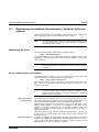
Protection against magnetic and electromagnetic fields during
operations and mounting
Magnetic and electromagnetic fields in the vicinity of current-carrying
conductors and permanent motor magnets represent a serious health
hazard to persons with heart pacemakers, metal implants and hearing
aids.
Health hazard for persons with heart pacemakers,
metal implants and hearing aids in proximity to
electrical equipment!
WARNING
⇒ Persons with pacemakers and metal implants are not
permitted to have access to the following areas:
- Areas in which electrical equipment and parts are
mounted, operating or are being commissioned.
- Areas in which parts of motors with permanent
magnets are being stored, repaired or mounted.
⇒ If it is necessary for a person wearing a heart
pacemaker to enter into such an area then a
physician must be consulted prior to doing so.
⇒ Persons with metal implants or hearing aids must
take care prior to entering into areas described
above. It is assumed that metal implants or hearing
aids will be consulted prior to doing so.
Protection during handling and installation
All Indramat products should be handled and assembled according to the
instructions in the documentation.
CAUTION
DOK-SYNAX*-SY*-06VRS**-FK01-EN-P
Risk of injury caused by crushing, shearing, cutting,
and thrusting movements!
⇒ Observe installation instructions and safety
regulations before handling and working on the
product.
⇒ Use suitable installation in using lifting or moving
equipment. Refer to the user manual for the product.
⇒ Take precautions to avoid pinching and crushing.
⇒ Only use suitable tools specified in the user manuals
and use them according the instructions.
⇒ Use lifting devices and tools correctly and safely.
⇒ Wear appropriate protective clothing, e.g., protective
goggles, safety shoes, protective gloves.
⇒ Never stand under suspended loads.
⇒ Clean up liquids from the floor to prevent personnel
from slipping.
1-22 Introduction
SYNAX
Battery safety
Batteries contain reactive chemicals. Incorrect handling can result in
injury or equipment damage.
Risk of injury due to incorrect handling!
CAUTION
Note:
⇒ Do not attempt to reactivate dead batteries by heating
or other methods (danger of explosion and
corrosion).
⇒ Never charge batteries (danger from leakage and
explosion).
⇒ Never throw batteries into a fire.
⇒ Do not take batteries apart.
⇒ Handle carefully. Incorrect extraction or installation of
a battery can damage equipment.
Environmental protection and disposal! The batteries
contained in the product should be considered as hazardous
material for land, air, and sea transport in the sense of the
legal requirements (danger of explosion). Dispose of batteries
separately from other refuse. Observe the legal requirements
in the country of installation.
DOK-SYNAX*-SY*-06VRS**-FK01-EN-P
SYNAX
Master axis and cam switch group
2
Master axis and cam switch group
2.1
General information on the master axis
2-1
The position of the master axis can be specified by either a real or a
virtual master axis.
real master axis
virtual master axis
master axis encoder
ϕ
L
CLC-D
"intelligent drive controller"
"ELS master - control word"
"master axis
following axis
ϕ
F
SY6FB012.FH7
Fig. 2-1: The master axis functions
It is basically irrelevant for the functioning of the following axis whether it
synchronizes with a real or a virtual master axis.
A virtual master axis does, however, have the following advantages in
comparison to a real master axis:
• the main shaft angular encoder is not needed
• greater running smoothness and more precise synchronism
• acceleration and deceleration can be precisely defined
Note:
DOK-SYNAX*-SY*-06VRS**-FK01-EN-P
One master axis revolution should basically equal one
machine cycle. One machine cycle corresponds, for example,
to one extrusion of a print format of a printing machine.
2-2 Master axis and cam switch group
2.2
SYNAX
Real master axis
The function of the real master axis
The movement of a following axis can be synchronized with that of a real
master axis. This requires the mounting of an angle encoder onto the
relevant master axis. Suitable encoders are listed in the "SYNAX project
planning" (DOK-SYNAX*-SY*-06VRS**-PR01-EN-P).
"intelligent
drive controller"
master axis
ϕ
master axis
encoder
L
"master axis
position"
following axis
ϕ
A:E
F
SY6FB013.FH7
Fig. 2-2: Real master axis with one following axis
The master encoder is connected to an encoder interface (ref. DOKSYNAX*-SY*-06VRS**-PR01-EN-P). The encoder interface may be an
optional plug-in module (drive families DIAX03, DIAX04) or an additional
on-board interface (ECODRIVE).
The evaluation of the master encoder may be configured for any
following axis in the system.
The master axis position is cyclically read by the CLC via the SERCOS
interface. The position value is extrapolated linearly and transmitted to all
following axes simultaneously.
The CLC is notified of the location of the encoder interface by means of
the parameter "real master - encoder drive address" (C-0-0005). The
drive address must be input.
There is no external signal to activate this master axis function. The CLC
starts working with the master axis as soon as the system is in operating
mode.
DOK-SYNAX*-SY*-06VRS**-FK01-EN-P
SYNAX
Master axis and cam switch group
2-3
Electronic measuring gear
The master axis establishes the reference of a following axis to a
product, e.g., printing format. That is why one master axis rotation should
always equal one machine cycle. It is often not possible to locate a
suitable mounting position for a master axis encoder that meets this
demand. In this case an electronic measuring gear can be used. This
gear is then programmed so that one rotation at the gear output equals
one product cycle.
Measuring gear
Master
encoder
Master encoder
- offset
Master encoder input revolutions
Master position,
0 ... 360 Degrees
C-0-0145
C-0-0144
Position feedback
value 3:
+
C-0-0066
+
Filter
P-0-0052
C-0-0146
C-0-0143
Offset position
feedback value 3:
Master position
in absolute format
(32 Bit incremental)
Master encoder output revolutions
P-0-0087
C-0-0148
Real master absolute
reference
Set absolute reference
_E:L01.24
Fig. 2-3: Electronic measuring gear
Note:
The electronic measuring gear is drive-supported as of
firmware ...-ELS-05V16 (DIAX03, DIAX04) and ...-SGP01V09 (ECODRIVE).
Measuring gear
The electronic measuring gear is drift-free. The "master encoder - input
revolutions" (C-0-0144) and "master encoder - output revolutions"
(C-0-0143) can be changed at any time.
If the gear values of the real master axis are altered while at standstill,
then the master axis position will not change immediately. The new
master axis position is not re-calculated until the next start-up.
If the ratio is altered while the real master axis is turning, then a new
master axis position is re-calculated immediately. No jump occurs in the
master axis position, but the master axis velocity (C-0-0067) does
change.
Note:
DOK-SYNAX*-SY*-06VRS**-FK01-EN-P
By changing the measuring gear, the absolute reference
between "position feedback value 3" (P-0-0052) and master
axis position is lost. It can be re-established with binary input
"real master - set absolute measuring" (_E:L01.24).
2-4 Master axis and cam switch group
SYNAX
Master axis position
Display formats
The master axis position (C-0-0066) displays the position within one
revolution in terms of 0° to 360°.
The "ELS master - actual position value absolute format" (C-0-0146)
specifies the position within 4096 revolutions. This position is displayed in
a 32 bit format (incremental). The value specified in bits 0 to 20 equals
the master axis position (C-0-0066); while bits 21 to 31 contain the
revolutions.
Reference
A master axis position in absolute format makes it possible to have
reference positions that exceed 360 degrees. If a multiturn encoder, e.g.,
a GDM, is used as a master axis encoder, then this master axis position
is unequivocally within 4096 revolutions. A rotation of the real master axis
of a maximum of + 2047 revolutions is detected upon switch-over into the
operating mode. This is taken into account when calculating the start
value.
If a single-turn encoder is used, e.g., GDS, then the position is only
unequivocal within one revolution. The number of revolutions in C-0-0146
is uncertain.
Offset
An offset between "actual position value 3" (P-0-0052) and the master
axis position can be specified ahead of the resolver gearbox with "offset
position feedback value 3" (P-0-0087) or after it with "master encoder offset" (C-0-0145).
Establishing the absolute master axis position
Using "set absolute dimension" the master axis position (C-0-0066 and
C-0-0146) can be set to a position pre-selected with parameter "real
master - absolute reference" (C-0-0148).
"Set absolute dimension" is activated with the binary input "set absolute
dimension" (_E:L01.24).
For reasons of precision, the absolute dimension should be set while the
real master axis is standing still.
The binary output "acknowledge set absolute dimension" (_A:L01.24)
signals that the master axis position relates to the absolute dimension.
DOK-SYNAX*-SY*-06VRS**-FK01-EN-P
SYNAX
Master axis and cam switch group
2-5
Actual value smoothing
A filter of higher order is used to smooth the signal of a real master axis
encoder. The signal noise on the master axis speed is filtered and
periodic interference can be damped.
Master encoder filter
Master
encoder
Smoothing: C-0-0042
Current phase
deviation:
C-0-0139
Maximum positive
phase deviation:
C-0-0140
Measuring
gear
Correction
Maximum negative
phase deviation:
C-0-0141
Phase correction: C-0-0136
Correction value smoothing: C-0-0138
Acceleration correction: C-0-0137
Fig. 2-4: Master axis filter of the real master axis
The filter time constant is set with parameter "real master - actual value
smoothing time constant" (C-0-0042).
The correction parameters C-0-0136, C-0-0137 and C-0-0138 are used
to minimize phase offset between input and output signals of the filter.
Note on adjusting the filter parameters
SynTop, the commissioning tool, is used to set the filter parameters. An
oscilloscope is also needed. In the SynTop dialog "Real master axis:
actual value smoothing" the parameters can be changed. The phase
deviations (C-0-0139, C-0-0140, C-0-0141) are cyclically displayed in the
dialog.
The master axis velocity is monitored with the oscilloscope. The analog
output of a drive controller is used for this.
The parameters are programmed in two steps:
• The filter to smooth master axis velocity is set in the first step.
• The smoothing filter generates an offset between the measured
encoder position and the master axis position at the output of the
filter. This phase offset is minimized in the second step with the help
of the correction parameter.
Smoothing the master axis velocity
The actual value smoothing uses filter time constant (C-0-0042). The
start value is a low value, e.g., 50ms.
The setting is conducted at a constant but low master axis velocity. While
monitoring the velocity on the oscilloscope, the time constant is
increased until the signal is sufficiently smoothed.
The setting thus found is then checked and possibly optimized, with two
to three velocities over a mean and a high velocity range.
DOK-SYNAX*-SY*-06VRS**-FK01-EN-P
2-6 Master axis and cam switch group
SYNAX
The correction parameters are not altered in the first step. They are
permanently set to the following values:
• Acceleration correction = 100 %
• Phase correction = 2 %
• Correction value smoothing = 15 ms
Correcting a phase shift
In the second step, the position offset between the measured (real) and
the smoothed master axis signal is minimized. The correction
parameters are used for this.
In addition to monitoring the master axis velocity during the optimizing
process, it is also necessary to monitor any phase offset. Since phase
offsets are not generated in the form of an analog signal, it is visualized
via the diagnosis parameters in the SynTop dialog. The current phase
deviations (C-0-0139) as well as maximum deviation in positive and
negative directions (C-0-0140, C-0-0141) are cyclically displayed in the
SynTop dialog. The maximum values must be set to zero prior to taking
each measurement.
It generally suffices to optimize phase correction (C-0-0136) and
smoothing correction (C-0-0138). Acceleration correction (C-0-0137)
generally retains ist standard value of 100%.
Optimization takes place at constant master axis velocity. Phase
correction is slowly increased which means that the phase offset
decreases. The signal noise is increased by switching phase correction
onto the master axis signal. The smoothing correction counteracts this
interference. It is necessary to set the smallest possible value since
smoothing correction influences the phase position of the correction.
To achieve an optimum setting, take measurements at various velocities.
In conclusion, check phase offset when running up and when braking.
Monitoring master axis position
When monitoring the master axis, any change in the position of the
master axis is recognized
• when the system is switched on and
• when the input "RM position monitoring enable" is set.
The monitoring function is performed once each time the machine is
switched on. As part of the procedure, the most recently stored position
is compared with the first actual position value read. The maximum
permissible deviation is determined in parameter "real master - position
window" (C-0-0025). If the current master axis position deviates from the
last one stored by a value greater than is permitted, then output "real
master moved" (_A:L01.08) is set to 1.
The message "real master moved" (_A:L01.08) is buffered until the
higher-ranking system, e.g., PLC, acknowledges. This also applies if the
machine is switched off when it is in an error state. It is acknowledged by
setting the input "real/virt. Master - clear error" (_E:L01.16). Output "real
master moved" (_A:L01.08) is also cancelled by the CLC when input
"real/virt. Master - clear error" (_E:L01.16) is set.
Monitoring can otherwise again be activated by setting input "RM position
monitoring enable" (_E:L01.15).
As long as this input is set, then output "real master moved" (_A:L01.08)
is set, if the real master axis is located outside of the position window.
DOK-SYNAX*-SY*-06VRS**-FK01-EN-P
SYNAX
Master axis and cam switch group
master axis
position
last
position
stored
moving the
master axis
360°
2-7
"real masterposition window"
(C-0-0025)
0°
machine operating
1
0
1
machine
OFF
running up
machine
machine operating
output
"real master moved" _A:L01.08
input
acknowledge: "real/virt. master - clear error" _E:L01.16
0
t
SY6FB015.FH7
Fig. 2-5: Real master axis: monitoring the master axis position
Monitoring the master axis encoder
A second, redundant encoder is mounted to the main shaft to monitor the
master axis encoder:
DDS
master axis
redundant
encoder
DDS
master
encoder
encoder
interface
master axis position
encoder
interface
SERCOS
interface
redundant master axis position
SY6FB016.FH7
Fig. 2-6: Real master axis with redundant encoder
Both encoders are connected to any two drives. The addresses of the
respective drives are entered in parameter "real master - encoder drive
address" (C-0-0005) and "real master - redundant encoder drive
address" (C-0-0072). Set in parameter "ELS master - control word"
(C-0-0004) whether the encoders will work in the same or opposite
direction.
Master axis encoder monitoring is automatically activated if a valid drive
address is entered in parameter "real master - redundant encoder drive
address" (C-0-0072).
The CLC cyclically reads both actual position values and generates the
absolute position difference. This difference is compared to a maximum
permissible deviation. The permissible deviation is set in parameter "real
master - redundant encoder monitoring window" (C-0-0073).
DOK-SYNAX*-SY*-06VRS**-FK01-EN-P
2-8 Master axis and cam switch group
Note:
SYNAX
As long as the maximum permissible deviation is not
exceeded, the real master axis will continue to follow the
master encoder.
If the position difference is outside of the monitoring window, then the
leading encoder is switched into. The CLC sets the outputs "virtual / real
master error" (_A:L01.03) and "real master axis - redundant encoder
error" (_A:L01.02). Until the error is cleared, the master axis will continue
to run with the actual value of the encoder which was acknowledged as
leading at the time the error occurred.
Note:
Inputting "real/virt. Master - clear error" (_E:L01.16) will
always switch into the master encoder.
master encoder position
redundant encoder position
actual
value
effective
master axis
position
position
difference
monitoring window
"real master axis - redundant encoder error"
SY6FB017.FH7
Fig. 2-7: Real master axis: monitoring master axis position
An error remains set until it is acknowledged ("real/virt. Master - clear
error", _E:L01.16). It is not even automatically cleared once the position
difference again is located within the monitoring window.
The peak value of the position difference is displayed in parameter "real
master - redundant encoder max. position difference" (C-0-0074) for use
with diagnostics and as an auxiliary value for the parametrization of the
monitoring window.
DOK-SYNAX*-SY*-06VRS**-FK01-EN-P
SYNAX
Master axis and cam switch group
2-9
Binary I/Os of the real master axis
Binary inputs of the real master axis
Designation
Function
_E:L01.15
RM position monitoring enable
_E:L01.16
Real/virt. Master - clear error
_E:L01.23
Real master - set absolute reference
_E:L01.24
Real master - set absolute measuring
Fig. 2-8: Binary inputs of the real master axis
Binary outputs of the real master axis
Designation
Function
_A:L01.02
RM redundant encoder error
_A:L01.03
Virtual/real master error
_A:L01.08
Real master moved
_A:L01.09
Real master positive direction
_A:L01.10
Virtual/real master standstill
_A:L01.23
Real master - set absolute reference acknowledge
_A:L01.24
Real master - set absolute measuring acknowledge
_A:L01.25
ELS master command value additive achieved
Fig. 2-9: Binary outputs of the real master axis
Rotational direction
The current direction of the master axis is signalled via output "real
master positive direction" (_A:L01.09). Positive velocity equals status "1".
Standstill message
If master axis velocity drops below the value in "real master - standstill
window" (C-0-0003), then output "virtual/real master standstill"
(_A:L01.10) is set.
speed of
master axis
standstill
window
output
"virt./real master
standstill" 1
_A:L01.10 0
output
"real master 1
positive direction" 0
_A:L01.09
t
SY6FB018.FH7
Fig. 2-10: Real master axis: standstill message and rotational direction
DOK-SYNAX*-SY*-06VRS**-FK01-EN-P
2-10 Master axis and cam switch group
SYNAX
Parameters for the real master axis
Below is a list of all CLC systems parameters needed to run the real
master axis.
(For details see "SYNAX Parameter Description", DOK-SYNAX*-SY*06VRS**-PA01-EN-P.)
Parameter
number
Designation
C-0-0003
Real master - standstill window
C-0-0004
ELS master - control word
C-0-0005
Real master - encoder drive address
C-0-0025
Real master - position window
C-0-0042
Real master - actual value smoothing time constant
C-0-0052
ELS master - speed operating points
C-0-0066
ELS master - actual position value
C-0-0067
ELS master - actual speed value
C-0-0072
Real master - redundant encoder drive address
C-0-0073
Real master - redundant encoder monitoring window
C-0-0074
Real master - redundant encoder maximum position
difference
C-0-0136
Real master - phase correction
C-0-0137
Real master - acceleration correction
C-0-0138
Real master - correction value smoothing time constant
C-0-0139
Real master - actual phase deviation
C-0-0140
Real master - maximum positive phase deviation
C-0-0141
Real master - maximum negative phase deviation
C-0-0143
Master encoder - output revolutions
C-0-0144
Master encoder - input revolutions
C-0-0145
Master encoder - offset
C-0-0146
ELS master - actual position value absolute format
C-0-0148
Real master - absolute reference
C-0-0149
ELS master command value additive
C-0-0150
ELS master command value offset speed
C-0-0161
ELS master command value additive - positive limit
C-0-0162
ELS master command value additive - negative limit
A-0-0159
ELS master command value additive selection
P-0-0052
Position feedback value 3 (for diagnostics only)
P-0-0053
Lead drive position
P-0-0059
SSI-emulator-resolution
P-0-0087
Offset position feedback value 3
P-0-0108
Leed drive polarity
only with FWA-DIAX03-ELS04VRS-MS:
P-0-0076
Interface position feedback value 3
P-0-0077
Position feedback 3 type parameter
only with FWA-DIAX03-ELS05VRS-MS
FWA-DIAX04-ELS05VRS-MS
FWA-ECODR3-SGP-01VRS-MS:
S-0-0115
Position feedback 2 type parameter
P-0-0185
Function of external encoder
Fig. 2-11: Parameters of the real master axis
DOK-SYNAX*-SY*-06VRS**-FK01-EN-P
SYNAX
2.3
Master axis and cam switch group
2-11
Virtual master axis
Functions of the virtual master axis
In systems with no real master axis, the virtual master axis fulfills the
purpose of generating arithmetic master axis positions. The master axis
position is calculated in a modulo format, a range of 0° to 360°, and
cyclically transmitted to the drives.
DDS
CLC
following axis
ϕ
master axis
position ϕ
L
A:E
F
SY6FB019.FH7
Fig. 2-12: Virtual master axis with one following axis
DOK-SYNAX*-SY*-06VRS**-FK01-EN-P
2-12 Master axis and cam switch group
SYNAX
Operating states
The virtual master axis is controlled with binary inputs. The following
figure depict the various operating states of the master axis dependent
on the binary inputs:
"enable"
=
virtual master - enable"
"stop"
=
"VM stop position 1 active" or
"E-stop"
=
"VM stop position 2 active"
"virtual master - E-stop"
n=0
STANDSTILL
"enable" = 1
and "stop" = 0
"enable" = 1
and "stop" = 1
"enable" = 1
and "stop" = 0
VIRTUAL MASTER
AXIS FOLLOWS
SETPOINT VALUE
"enable" = 1
and "stop" = 1
POSITIONING
"enable" = 0
"enable" = 1
and "stop" = 0
"enable" = 1
and "stop" = 1
STOP
"E-Stop" = 1
E-STOP
SY6FB020.FH7
Fig. 2-13: Operating states of the virtual master axis
State
Movement initiated
STANDSTILL
master axis velocity = 0
VIRTUAL
MASTER AXIS
FOLLOWS
VELOCITY
COMMAND
VALUE
In the simplest case, the virtual master axis always
follows the current speed command value (see " Basic
function", page 2-13). The binary inputs for activating a
stop position are not used.
STOPPING
The master axis brakes until standstill with "virtual
master - deceleration" (C-0-0009) . No stop position is
approached.
POSITIONING
The master axis moves to a selected stop position (see
"Positioning", page 2-15).
E-STOP
The master axis brakes until standstill with "virtual
master - emergency stop deceleration" (C-0-0010) . No
stop position is approached.
Fig. 2-14: Operating states
DOK-SYNAX*-SY*-06VRS**-FK01-EN-P
SYNAX
Master axis and cam switch group
2-13
Basic function
The virtual master axis is enabled with the input signal "virtual master
enable" (_E:L01.06). As long as this signal is applied, position setpoint
values are generated and cyclically transmitted to the following axes.
If no stop position is active (see "Positioning", page 2-15), then the
master axis will continue to adhere to the speed command value.
It is possible to program different ramps for velocity changes and master
axis braking. The parameter "virtual master - bipolar acceleration"
(C-0-0008) is active when accelerating the master axis, when
approaching a stop position, and when changing setpoint values.
The ramp for decelerating to a standstill is set with the parameter "virtual
master - deceleration" (C-0-0009). This parameter is activated when the
master axis is stopped by cancelling the input "virtual master enable"
(_E:L01.06).
If the signal "virtual master enable" (_E:L01.06) is again set when
decelerating to a standstill, then the master axis will accelerate to the
current speed command value (C-0-0006 or C-0-0054).
The acceleration change is limited by the parameter "virtual master bipolar jerk" (C-0-0077). The jerk limit affects both the "virtual master bipolar acceleration" (C-0-0008) and the "virtual master - deceleration"
(C-0-0009).
master axis
jerk
virtual master - bipolar jerk (C-0-0077)
master axis
acceleration
virtual master bipolar acceleration (C-0-0008)
master axis
speed
virtual master - deceleration (C-0-0009)
C-0-0006 or C-0-0054
master axis
position
360°
0°
input "virtual master enable" (_E:L01.06)
1
0
1
0
input "virtual master stop position n active" (_E:L01.07 or _E:L01.08)
t
SY6FB021.FH7
Fig. 2-15: Virtual master axis - basic functions
DOK-SYNAX*-SY*-06VRS**-FK01-EN-P
2-14 Master axis and cam switch group
SYNAX
Master axis velocity source
The setpoint value is specified by either the parameter "virtual master speed command 1" (C-0-0006) or by one of the velocities in parameter
"virtual master - speed commands" (C-0-0054).
Parameter "ELS master - control word" (C-0-0004) sets whether one
speed command (C-0-0006) or eight speed command values (C-0-0054,
selected via the I/Os) are used.
Selection in
parameter
C-0-0004
Inputs for selecting
velocity command value
_E:L01.09, _E:L01.10,
_E:L01.11
Active
velocity
command value
bit 15 = 0
x
C-0-0006
bit 15 = 1
000
C-0-0054 Element 1
100
C-0-0054 Element 2
010
C-0-0054 Element 3
110
C-0-0054 Element 4
001
C-0-0054 Element 5
101
C-0-0054 Element 6
011
C-0-0054 Element 7
111
C-0-0054 Element 8
Fig. 2-16: Master axis velocity values
The master axis velocity can be altered during operation by
• writing in parameter C-0-0006 or C-0-0054 or
• by using the jog inputs.
Virtual master - speed command presetting
If the input "virtual master - speed command preset" (_E:L01.02) is active
when switching the eight speeds, then the newly selected speed is preset
with the value preset in "virtual master - speed command pre-setting"
(C-0-0053).
Given a positive edge "virtual master - speed command preset"
(_E:L01.02), then the currently selected speed is preset with the relevant
element from parameter "virtual master - speed command pre-setting"
(C-0-0053).
Jogging master axis velocity
Jogging inputs "virtual master jog -" (_E:L01.12) and "virtual master jog
+" (_E:L01.13) affect the active speed command value.
A quick signal at one of the jogging input alters velocity by a fixed amount
(incremental width). This incremental width, given in rpm/min., can be
programmed. If a jogging signal is applied for any length of time, then the
velocity is continuously changed by the set incremental width.
DOK-SYNAX*-SY*-06VRS**-FK01-EN-P
SYNAX
Master axis and cam switch group
2-15
Limiting master axis velocity
The parameter "virtual master speed 1 - positive limit" (C-0-0030) and
"virtual master speed 1 - negative limit" (C-0-0031) make it possible to
set a permissible velocity range. This limit directly effects parameter
"virtual master - speed command 1" (C-0-0006).
If eight speed command values are used, then the parameters "virtual
master - speed command positive limits" (C-0-0055) and "virtual master speed command negative limits" (C-0-0056) limit parameter "virtual
master - speed commands" (C-0-0054).
Positioning
The positioning mode of the virtual master axis permits a precise
deceleration to a stop position and approaching a new position out of
standstill.
The binary inputs "VM stop position 1 active" (_E:L01.07) and "VM stop
position 2 active" (_E:L01.08) are used for positioning. Each of these
inputs has assigned to it one C parameter "virtual master - stop position
1" (C-0-0026) or "virtual master - stop position 2" (C-0-0027). A stop
position is activated by setting the corresponding input.
Note:
If both inputs "VM stop position 1 active" (_E:L01.07) and "VM
stop position 2 active" (_E:L01.08) are set simultaneously,
then position 2 takes precedence.
Approaching a stop position
If the "virtual master enable" (_E:L01.06) is applied, then the master axis
accelerates to the speed command. If, at this point, an input "virtual
master axis - stop position n active" is also set, then the selected stop
position is approached.
At first, the master axis continues with the current velocity and then
brakes with "acceleration bipolar" to the stop position. Once the position
has been reached, output "virtual master - in position" (_A:L01.19) is set.
DOK-SYNAX*-SY*-06VRS**-FK01-EN-P
2-16 Master axis and cam switch group
SYNAX
master axis
speed
master axis
position
stop position 1
input
"virtual master
enable"
(_E:L01.06)
1
0
output
"virtual master
stop position 1
active" (_E:L01.07)
output
"virtual master
in position"
(_A:L01.19)
output
"virt./real master
standstill"
(_A:L01.10)
1
0
1
0
1
0
t
SY6FB022.FH7
Fig. 2-17: Virtual master axis - approaching a stop position
Starting up out of a stop position
The inputs "virtual master enable" (_E:L01.06) and "VM stop position n
active" are set and the master axis is standing.
• If a new value is written over the existing activated stop position, then
the master axis will move to the new stop position. The positioning
direction is set by the polarity of the current speed command value.
"Virtual master - bipolar acceleration" (C-0-0008) and "virtual master bipolar jerk" (C-0-0077) take effect when accelerating to positioning
speed and when braking. Positioning speed is limited to the current
speed command value.
• If input "virtual master axis - stop position n active" is cancelled, then
the master axis will accelerate to the current speed command value.
Positioning interrupt
If "virtual master enable" (_E:L01.06) is cancelled during the positioning
procedure, then the master axis will brake immediately to standstill with
"virtual master - deceleration" (C-0-0009).
If input "virtual master axis - stop position n active" is cancelled during
positioning, then the master axis will again follow the current speed
command value.
DOK-SYNAX*-SY*-06VRS**-FK01-EN-P
SYNAX
Master axis and cam switch group
Binary I/O of the virtual master axis
The binary inputs of the virtual master axis
Designation
Function
_E:L01.01
Virtual master E-stop
_E:L01.02
VM speed command preset
_E:L01.03
--
_E:L01.04
--
_E:L01.05
Switch to virtual master
_E:L01.06
Virtual master enable
_E:L01.07
VM stop position 1 active
_E:L01.08
VM stop position 2 active
_E:L01.09
VM selection of speed cmd bit 0
_E:L01.10
VM selection of speed cmd bit 1
_E:L01.11
VM selection of speed cmd bit 2
_E:L01.12
Virtual master jog -
_E:L01.13
Virtual master jog +
_E:L01.14
VM jogging speed reduced
_E:L01.15
RM position monitoring enable
_E:L01.16
Real/Virt. master - clear error
...
...
_E:L01.20
VM preset position
_E:L01.25
ELS master command value additive - enable
Fig. 2-18: Binary inputs of the virtual master axis
The binary outputs of the virtual master axis
DOK-SYNAX*-SY*-06VRS**-FK01-EN-P
Designation
Function
_A:L01.01
Virtual master E-Stop
_A:L01.02
RM redundant encoder error
_A:L01.03
Virtual/Real master error
_A:L01.04
--
_A:L01.05
Virtual master axis active
_A:L01.06
VM enable acknowledge
_A:L01.07
VM speed command value achieved
_A:L01.08
Real master moved
_A:L01.09
Real master positive direction
_A:L01.10
Virtual/real master standstill
_A:L01.11
VM speed switching signal 1
_A:L01.12
VM speed switching signal 2
_A:L01.13
VM speed switching signal 3
_A:L01.14
VM speed switching signal 4
_A:L01.15
VM speed switching signal 5
_A:L01.16
VM speed switching signal 6
_A:L01.17
VM speed switching signal 7
_A:L01.18
VM speed switching signal 8
2-17
2-18 Master axis and cam switch group
SYNAX
_A:L01.19
Virtual master in position
_A:L01.20
VM preset position acknowledge
_A:L01.21
VM negative jogging limit exceeded
_A:L01.22
VM positive jogging limit exceeded
_A:L01.25
ELS master command value additive achieved
Fig. 2-19: Binary outputs of the virtual master axis
Enable
Once input "virtual master enable" (_E:L01.06) is set, the master axis
accelerates with the velocity specified by "virtual master - bipolar
acceleration" (C-0-0008) to the velocity set in "virtual master - speed
command 1" (C-0-0006) or "virtual master - speed command"
(C-0-0054).
Once master axis velocity has reached the command value, then output
signal "VM speed command value achieved" (_A:L01.07) is set.
A removal of the enable signal means that braking is initiated with the
decel value set in parameter "virtual master - deceleration" (C-0-0009).
master axis
acceleration
(C-0-0008)
(C-0-0008)
(C-0-0009)
new speed command value
master axis
speed
input
"virtual master
enable" 1
(_E:L01.06) 0
output
"virtual master speed 1
command value
0
achieved" (_A:L01.07)
output
1
"virtual/real
0
master standstill"
(_A:L01.10)
t
SY6FB023.FH7
Fig. 2-20: Diagram of a simple switching on and off during idle mode
Standstill signal
The output "Virtual/real master standstill" (_A:L01.10) is set to 1 once the
master axis is standing.
DOK-SYNAX*-SY*-06VRS**-FK01-EN-P
SYNAX
Master axis and cam switch group
2-19
E-stop
Input signal "virtual master E-stop" (_E:L01.01) immediately initiates
braking to the point of standstill using the deceleration value which has
been programmed. The CLC confirms the E-stop with the output signals
"virtual/real master E-stop" (_A:L01.01) and "virtual/real master error"
(_A:L01.03).
To deactivate the E-stop, it is necessary to
• cancel the E-stop input and
• set the input "virtual/real master - clear error" (_E:L01.16).
The outputs "virtual/real master E-stop" (_A:L01.01) and "virtual/real
master error" (_A:L01.03) are then cancelled.
master axis
acceleration
C-0-0008
C-0-0010
master axis
speed
input
"idle mode acknowledge" (_E:F#.6)
1
0
input
"virtual master E-stop" (_E:L01.01)
1
0
input
"virt./real master clear error" (_E:L01.16)
1
0
output
"virtual master E-stop acknowledge"
(_A:L01.01)
1
0
output
"virtual/real master error" (_A:L01.03)
1
0
t
SY6FB024.FH7
Fig. 2-21: E-stop function of the virtual master axis
The emergency stop is not generally equipped with jerk limit. If
deceleration with jerk-limit is needed, then it can be activated in "ELS
master - control word" (C-0-0004):
Parameter
C-0-0004
Emergency stop with jerk limit
Bit 8 = 0
not active
Bit 8 = 1
active
Fig. 2-22: Emergency stop with jerk limit
If the jerk limit is active, then parameter "virtual master - bipolar jerk"
(C-0-0077) is also effective.
DOK-SYNAX*-SY*-06VRS**-FK01-EN-P
2-20 Master axis and cam switch group
SYNAX
Parameters for operating the virtual master axis
The following is a list of all relevant CLC system parameters required to
operate the virtual master axis.
(For details see "SYNAX Parameter Description", DOK-SYNAX*-SY*06VRS**-PA01-EN-P.)
Parameter
number
Designation
C-0-0004
ELS master - control word
C-0-0006
Virtual master - speed command 1
C-0-0008
Virtual master - bipolar acceleration
C-0-0009
Virtual master - deceleration
C-0-0010
Virtual master - emergency stop deceleration
C-0-0026
Virtual master - stop position 1
C-0-0027
Virtual master - stop position 2
C-0-0028
Virtual master - speed increment
C-0-0030
Virtual master speed 1 - positive limit
C-0-0031
Virtual master speed 1 - negative limit
C-0-0045
Reserved (virtual master - position increment)
C-0-0052
ELS master - speed operating points
C-0-0053
Virtual master - speed command presetting
C-0-0054
Virtual master - speed commands
C-0-0055
Virtual master - speed command positive limits
C-0-0056
Virtual master - speed command negative limits
C-0-0066
ELS master - actual position value
C-0-0067
ELS master - actual speed value
C-0-0075
Virtual master - preset position
C-0-0077
Virtual master - bipolar jerk
C-0-0149
ELS master command value additive
C-0-0150
ELS master command value additive
C-0-0160
ELS master - actual additive position value
C-0-0161
ELS master command value additive - positive limit
C-0-0162
ELS master command value additive - negative limit
A-0-0159
ELS master command value additive selection
P-0-0053
Lead drive position
P-0-0059
SSI-emulator-resolution
P-0-0108
Lead drive polarity
Fig. 2-23: Parameters for operating the virtual master axis
DOK-SYNAX*-SY*-06VRS**-FK01-EN-P
SYNAX
2.4
Master axis and cam switch group
2-21
Additive master axis command value
A "ELS master - command value additive" (C-0-0149) can be added to
the position of a virtual or a real master axis. This can be used to offset
the master axis over the entire SYNAX ring or any selected following
axis. Each slave axis can be programmed as to whether the additive
component effects a drive or not with parameter "ELS master - command
value additive selection" (A-0-0159):
• A-0-0159 = 0: master axis command value additive not effective
• A-0-0159 > 0: master axis command value additive effective
In applications with one CLC control, any value ranging from 1 to 32
can be set in A-0-0159.
In the CLC link of several CLC controls, " ELS master - command
value additive " (C-0-0149) can work beyond the CLC (see section
13.10 "Additive master axis command value in the CLC link"). The
address of the CLC which distributes the additive command value
within the CLC link must then be entered in parameter A-0-0159.
A change of the additive position command value is performed with the
"ELS master - command value offset speed" (C-0-0150). Once the
parametrized value is reached, then binary output "position command
value additive achieved" (_A:L01.25) is set.
ELS master
command additive Enable
Offset speed
Master
command value
additive
C-0-0149
Master - actual
position value
C-0-0150
+
C-0-0066
Master
position:
P-0-0053
P-0-0053
Command
value
additive
selection:
A-0-0159
A-0-0159
=0
=0
Command value additive
not effective
P-0-0053
P-0-0053
P-0-0053
A-0-0159
A-0-0159
A-0-0159
=1
=1
=1
Command value additive
effective
Fig. 2-24: The effects of the "master axis position command value additive"
DOK-SYNAX*-SY*-06VRS**-FK01-EN-P
2-22 Master axis and cam switch group
SYNAX
The "ELS master - command value additive" must be enabled using a
binary input. The additive command value is taken into account only if
input "ELS master command value additive - enable" (_E:L01.25) is set.
Master
position
Master
speed
Master cmd. value
additive (C-0-0149)
*)
Actual master cmd.
additive (C-0-0160)
ELS master command value additive - Enable
Fig. 2-25: ELS master command value additive - Enable
∗ If the enable signal is reset during an offset adjustment, the additive
component is no longer added to the master position. A remainining
command difference is buffered and is taken into account with the
next raising edge at the enable input.
Note:
2.5
Neither a jerk nor an acceleration limit for the offset results so
that only very slow offset speeds make sense.
Standard cam switches
Depending upon the angle position of the master axis, the standard cam
switches can be used to switch signals on and off. The ON actuating and
OFF actuating angles can be programmed. Six cams are available for
this purpose.
The standard cam switches can be used with either the real or the virtual
master axis.
The standard cam swtiches are always active. No external signal is
needed to switch this function on.
Standard cam switches are suitable for simple applications only.
Example: Aligning a master axis encoder.
DOK-SYNAX*-SY*-06VRS**-FK01-EN-P
SYNAX
Master axis and cam switch group
2-23
Binary I/Os of the standard cam switches
Each cam has an output "virtual/real master cam switch bit n" assigned
to it. Output n is set if the master axis position exceeds the value "cam
switch bit n actuating angle".
An example for three cams is listed below:
Standard cam switch bit 1 ON angle
= 90°
Standard cam switch bit 1 OFF angle
= 225°
Standard cam switch bit 2 ON angle
= 330°
Standard cam switch bit 2 OFF angle
= 20°
Standard cam switch bit 3 ON angle
= 200°
Standard cam switch bit 3 OFF angle
= 240
The following outputs are available on the CLC for the cam switches:
Designation
Function
_A:N01.01
Standard cam switch bit 1
_A:N01.02
Standard cam switch bit 2
_A:N01.03
Standard cam switch bit 3
_A:N01.04
Standard cam switch bit 4
_A:N01.05
Standard cam switch bit 5
_A:N01.06
Standard cam switch bit 6
Fig. 2-26: Standard cam switch outputs
360°
270°
180°
90°
0°
outputs
1
0
1
0
1
0
cam switch 1
(_A:N01.01)
cam switch 2
(_A:N01.02)
cam switch 3
(_A:N01.03)
SY6FB025.FH7
Fig. 2-27: Standard cam switch with three cams
DOK-SYNAX*-SY*-06VRS**-FK01-EN-P
2-24 Master axis and cam switch group
SYNAX
Parameters of the standard cam switch
The following is a list of all relevant CLC system parameters for the
standard cam switches.
(For details see "SYNAX Parameter Description", DOK-SYNAX*-SY*06VRS**-PA01-EN-P.)
Parameter
number
Designation
C-0-0016
Cam switch group 1 - switch 1 ON angle
C-0-0017
Cam switch group 1 - switch 1 OFF angle
C-0-0018
Cam switch group 1 - switch 2 ON angle
C-0-0019
Cam switch group 1 - switch 2 OFF angle
C-0-0020
Cam switch group 1 - switch 3 ON angle
C-0-0021
Cam switch group 1 - switch 3 OFF angle
C-0-0022
Cam switch group 1 - switch 4 ON angle
C-0-0023
Cam switch group 1 - switch 4 OFF angle
C-0-0034
Cam switch group 1 - switch 5 ON angle
C-0-0035
Cam switch group 1 - switch 5 OFF angle
C-0-0036
Cam switch group 1 - switch 6 ON angle
C-0-0037
Cam switch group 1 - switch 6 OFF angle
Fig. 2-28: Parameter for standard cam switch
2.6
High speed standard cam switch
Functional Principle
Depending on the position of the angle of the master axis, the high-speed
cam switch can be used to set binary outputs. The cams can be output
on an I/O card in the drive, an I/O card in a CCD box or on the dual port
RAM of a CLC-P. Up to 32 high-speed cams can be parametrized
depending on the output unit.
The high speed cam switches can be used with either the real or the
virtual master axis.
An output n is set if the master axis position lies between "high speed
cam switch n - on angle" and "high speed camswitch n - off angle".
Example
360°
270°
180°
90°
0°
outputs
high speed
cam 1
1
0
1
0
1
0
high speed cam 2
high speed cam 3
SY6FB026.FH7
Fig. 2-29: High speed cam switch with three cams
DOK-SYNAX*-SY*-06VRS**-FK01-EN-P
SYNAX
Master axis and cam switch group
High speed cam switch 1 - ON angle
= 90°
High speed cam switch 1 - OFF angle
= 225°
High speed cam switch 2 - ON angle
= 330°
High speed cam switch 2 - OFF angle
= 20°
High speed cam switch 3 - ON angle
= 200°
High speed cam switch 3 - OFF angle
= 240°
2-25
Configuration
output:
I/O card(s) at the drive
C-0-0050
max. 2 cards with
16 cams each
switch ON angle 1
switch OFF anlge1
DEA 04
master axis
position
switch ON angle 2
switch OFF angle 2
DEA08
max. 24 cams
high speed
standard
cam switch
cycle time:
t SERCOS
I/O card at CCD-box
control word
C-0-0049
DEA 28
max. 24 cams
switch ON angle 32
switch OFF angle 32
DPRAM of a CLC-P
max. 32 cams
SY6FB143.FH7
Fig. 2-30:
:
High-speed cam output
The output unit and the number of high-speed cams are configured in
"high speed cam switches - control word" (C-0-0049):
C-0-0049
Bit 1- 0
Number of high speed cams
0 0
High speed cam switches not active
0 1
16 at DEA04
1 0
24 at DEA08 and DEA28
32 at DEA04 and DPRAM
Fig. 2-31: Number of high speed cams
DOK-SYNAX*-SY*-06VRS**-FK01-EN-P
2-26 Master axis and cam switch group
SYNAX
C-0-0049
Bit 9 - 8
Cam output on ...
0 0
1...2 I/O cards - type DEA04
0 1
dual port RAM of an CLC-P
1 0
1 I/O card - type DEA28
1 1
1 I/O card - type DEA08
0 0
High-speed cams can be used in the I/O logic if all
A-0-0036 = 0
Fig. 2-32: Selecting the output unit
If cams are output via input modules in the drive (DEA04, DEA08), then
the I/O card must be configured in parameter "digital I/O status"
(A-0-0036) for the relevant drive.
A-0-0036
Configuration
bit 1 = 0
no DEA for high speed cam
bit 1 = 1
I/O card for high speed cam
inserted
Fig. 2-33: Settings in parameter A-0-0036
Output via DEA04
Up to 16 cams can be output on a maximum of two I/O cards, type
DEA04. The I/O cards are inserted into any two drive controllers.
The cams are allocated to the DEA cards in such a way that cams 1
through 16 are assigned to the cards with the low drive addresses, while
the cards with the higher addresses are used for cams 17 to 32. The
cams are counted according to the sequence of the ON and OFF
actuating angles in the "high speed cam switches - ON/OFF angle"
(C-0-0050).
DEA04 pin assignment:
Cams 1 ... 16
Cams 17 ... 32
Pin
Pin
reserved for
1
reserved for
1
..
Binary inputs
..
for the I/O logic
15
..
Binary inputs
..
for the I/O logic
15
16
High Speed Cam 1
16
High Speed Cam 17
17
High Speed Cam 2
17
High Speed Cam 18
18
High Speed Cam 3
18
High Speed Cam 19
..
.....
..
.....
..
.....
..
.....
31
High Speed Cam 16
31
High Speed Cam 32
35
external power supply,
ground
35
external power supply,
ground
37
external power supply, 24 V
37
external power supply, 24 V
Fig. 2-34: DEA04 assignment with the use of high-speed cams
DOK-SYNAX*-SY*-06VRS**-FK01-EN-P
SYNAX
Master axis and cam switch group
2-27
Output via DEA08
Up to 24 cams can be output on one I/O card, type DEA08. The DEA08
is inserted into any drive controller.
DEA08 pin assignment:
Pin
Assignment
1 ... 11
binary inputs of the I/O logic
22 ... 32
-"-
43 ... 52
-"-
12 ... 19
high-speed cam 1 ... 8
33 ... 40
high-speed cam 9 ... 16
53 ... 60
high-speed cam 17 ... 24
21, 42, 62
external supply, ground
41, 61
external supply, 24 V
Fig. 2-35: DEA08 assignment with the use of high-speed cams
Output via DEA28
Up to 24 cams can be output on one I/O card, type DEA28. The DEA28
is available as a plug-in card for the CLC-D in a CCD box.
Pin assignment for DEA28: same as DEA08.
Output via dual port RAM
Up to 32 cams can be output in the DPRAM of a CLC-P. The cams are
written behind the feedback values of the master axis into the ’real-time
data feedback value buffer’ (address offset 0x0808).
Note:
I/O card outputs not used may not be used as binary output
signals for the I/O logic.
Parameters for high speed cam switches
The following lists all CLC parameters for the high speed cam switches.
Parameter
number
Designation
C-0-0049
High speed cam switches - control word
C-0-0050
High speed cam switches - ON/ OFF angle
C-0-0130
Internal I/O: high speed cam switches outputs (for
diagnostics)
A-0-0036
Digital I/O - configuration
Fig. 2-36: Parameter for high speed cam switch
DOK-SYNAX*-SY*-06VRS**-FK01-EN-P
2-28 Master axis and cam switch group
2.7
SYNAX
Speed operating points
With the speed switching signals functions specific to the applications
can be activated according to the speed of the master axis. Binary
outputs are set or reset when speeds exceed programmable values.
Speed operating points are programmed in rpm. One binary output is
assigned to every two operating points. Eight outputs are available.
Speed switching signals are always output in terms of the effective
master axis speed.
Binary I/O
master axis
speed
[rpm]
upper
speed switching point 2
upper speed switching point 1
lower speed switching point 1
lower
speed switching
point 2
outputs
speed switching signal 1
_A:L01.11
1
0
1
0
speed switching signal 2
_A:L01.12
SY6FB027.FH7
Fig. 2-37: Virtual master axis with two speed switching points
Internal outputs
Output
Function
A:L01.11
VM speed switching signal 1
A:L01.12
VM speed switching signal 2
A:L01.13
VM speed switching signal 3
A:L01.14
VM speed switching signal 4
A:L01.15
VM speed switching signal 5
A:L01.16
VM speed switching signal 6
A:L01.17
VM speed switching signal 7
A:L01.18
VM speed switching signal 8
Fig. 2-38: Internal outputs
DOK-SYNAX*-SY*-06VRS**-FK01-EN-P
SYNAX
Master axis and cam switch group
2-29
Parameters for the speed switching point
The following is a list of all CLC system parameters relevant to the speed
switch group.
Parameter
number
Designation
C-0-0052
ELS master - speed operating points
Fig. 2-39: Parameter for the speed switching signals
2.8
Master toggle mode between real and virtual master axes
Function description
The master toggle mode makes it possible to changeover from real to
virtual master axis during operation. This means that all drives are
switched which are assigned as following axes to the master axis of a
SYNAX ring.
The master toggle mode between real and virtual master axis is set in
parameter "ELS master - control word" (C-0-0004) using one of the
following bit combinations:
Parameter C-0-0004
Command value source (see
"Basic function", page 2-13)
00000000 00x10001
C-0-0006
10000000 00x10001
C-0-0054
Fig. 2-40: Bit combination for master toggle mode
For the master toggle mode, the real master function must be preset
(see table above, bit 0 in "ELS master - control word").
The changeover between real and virtual master axis takes place via the
binary input "switch to virtual master" (_E:L01.05). The output "virtual
master axis active" (_A:L01.05) specifies which master axis has the lead.
It applies:
Output
"Switch to virtual master"
positive edge
change to virtual master axis
negative edge
change to real master axis
Output
"virtual master axis active"
0
real master axis active
1
virtual master axis active
Fig. 2-41: Definition of the I/Os
The state of the system is buffered on the CLC. This guarantees that the
previously valid state is displayed with output "virtual master axis active"
(_A:L01.05) upon powering up.
DOK-SYNAX*-SY*-06VRS**-FK01-EN-P
2-30 Master axis and cam switch group
SYNAX
Change from real to virtual master axis
The change from real to virtual master axis is triggered by a positive
edge at input "switch to virtual master" (_E:L01.05). The virtual master
axis restarts with the current values of position and speed of the real
master axis. It then becomes the master axis for the following axes.
The behavior of the virtual master axis after the changeover depends on
the state of the binary inputs at the time of the changeover and on the
command value source which has been set. Inputs "virtual master
enable" (_E:L01.06), "virtual master stop position 1 active" (_E:L01.07)
and "virtual master stop positon 2 active" (_E:L01.08) determine whether
the master axis stops immediately, travels to a stop position or follows
the current speed command value. The command value source
(C-0-0006 or C-0-0054) determines the speed of the virtual master axis
after the changeover.
The effects of binary inputs "virtual master enable" (_E:L01.06) and "VM
stop position n active":
Enable
Stop
active
Behavior of the virtual master axis after
switching
0
x
Behavior
The master axis brakes with "virtual master deceleration" (C-0-0009) to standstill.
1
0
Continue at constant velocity
The virtual master axis restarts with the actual velocity of
the real master axis and then follows the current velocity
command value.
1
1
Positioning
The virtual master axis restarts with the actual velocity of
the real master axis and the proceeds to the selected
stop position.
Fig. 2-42: The effects of "virtual master enable" (_E:L01.06) and "VM stop
position n active":
Effective velocity command value:
Command
value source
(bit 15,
C-0-0004)
Velocity
select
(binary
inputs)
Velocity command value of the
virtual master axis
after changeover
C-0-0006
xxx
preset velocity (C-0-0006) effective
C-0-0054
bit
2 1
0 0
0 1
0 1
1 0
1 0
1 1
1 1
C-0-0054
0
1
0
1
0
1
0
1
bit
2 1 0
0 0 0
preset velocity (element of the command
value list selected C-0-0054) effective
the speed of the real master axis at the
time of changeover is copied into the first
element of the command value list
C-0-0054 and is effective as the command
value.
Fig. 2-43: Effective velocity command value
DOK-SYNAX*-SY*-06VRS**-FK01-EN-P
SYNAX
Master axis and cam switch group
2-31
Approaching a stop position
If the virtual master axis is to travel to a stop position after the
changeover, then the input "virtual master enable" (_E:L01.06) and one
of the inputs "VM stop position n active" must be set at the time of the
changeover (positive edge at input "switch to virtual master", _E:L01.05).
real
master
axis
position
real master standstill
virtual
master
axis
position
position at the time of
master axis changeover
stop
position 1
master
axis
velocity
real
1
0
inputs
outputs
virtual
"change-over to virtual master" (_E:L01.05)
1
0
"virtual master enable" (_E:L01.06)
1
0
"virtual master stop position 1 active" (_E:L01.07)
1
0
"virtual master axis active" (_A:L01.05)
1
0
"virtual master in position" (_A:L01.19)
1
0
"Virtual/Real master standstill" (_A:L01.10)
t
SY6FB028.FH7
Fig. 2-44: Changeover of real to virtual master axis with active stop position 1
DOK-SYNAX*-SY*-06VRS**-FK01-EN-P
2-32 Master axis and cam switch group
SYNAX
Travel with preset velocity
If input "virtual master enable" (_E:L01.06) is set at changeover and no
stop position is active, then the master axis will follow the current velocity
command value. Depending upon what has been set in "ELS master control word" (C-0-0004), the command value is taken either from
parameter "virtual master - speed command 1" (C-0-0006) or "virtual
master - speed commands" (C-0-0054). After changeover, the virtual
master axis either accelerates or decelerates to the current command
value.
If command value list C-0-0054 has been set as the command value
source, in order to be able to assume a preset command value it is
necessary to select a list element other than element ’0’. The selection is
made via the three binary inputs "VM selection of speed cmd bit n" (see
"Basic function", page 2-13).
The bit combination ’000’ triggers the special function described in the
following section.
real
master
axis
position
real master standstill
position at the time of
master axis changeover
virtual
master
axis
position
C-0-0006
master
axis
velocity
real
virtual
1
0
"change-over to virtual master axis" (_E:L01.05)
1
0
"virtual master enable" (_E:L01.06)
1
0
"virtual master axis active" (_A:L01.05)
inputs
outputs
1
0
"virtual master speed
command value achieved" (_A:L01.07)
t
SY6FB029.FH7
Fig. 2-45: Changeover from real to virtual master axis with constant velocity
(C-0-0006)
DOK-SYNAX*-SY*-06VRS**-FK01-EN-P
SYNAX
Master axis and cam switch group
2-33
Changeover with "real" velocity
If command value list C-0-0054 is set as command value source and the
first element of the command list has been selected (bit combination
’000’) via the three binary inputs "VM selection of speed cmd bit n", then
the current velocity command value of the real master axis is taken over
at the time of switching into the first report group elementary item.
The limit values (C-0-0055 and C-0-0056) apply to the command value
list C-0-0054 when the velocity command value is assumed. If the
velocity of the real master axes should exceed the prorammed limits,
then the respective limit value will be written into the first report group
elementary item of the current actual value and be effective as the new
command value.
real
master
axis
position
real master standstill
position at the time of
master axis switching
virtual
master
axis
position
C-0-0054, first element
master
axis
velocity
inputs
outputs
real
virtual
1
0
"change-over to virtual master" (_E:L01.05)
1
0
"virtual master enable" (_E:L01.06)
1
0
"virtual master selection of speed command bit 0" (_E:L01.09)
1
0
"virtual master selection of speed command bit 1" (_E:L01.10)
1
0
"virtual master selection of speed command bit 2" (_E:L01.11)
1
0
"virtual master axis active" (_A:L01.05)
1
0
"virtual master speed
command value achieved " (_A:L01.07)
SY6FB030.FH7
Fig. 2-46: Change to virtual master axis with assumption of real velocity
(C-0-0054)
DOK-SYNAX*-SY*-06VRS**-FK01-EN-P
2-34 Master axis and cam switch group
SYNAX
Changeover from virtual to real master axis
The changeover from virtual to real master axis is triggered by a negative
edge at input "switch to virtual master" (_E:L01.05). The real master axis
guides the following axis once the virtual master is standing and the real
master has passed the virtual master.
If the actual position value of the real master axis is different from that of
the virtual master axis position at the time of changeover, then no
command values are transmitted to the following axis for the time being.
This represents an abrupt change in the command value. Command
value transmission is activated when the real master axis achieves the
actual position of the virtual master axis.
virtual
master
axis
positio
n
standstill of
virtual master axis
position at time of
master axis switch
real master
axis position
standstill of real master axis
effective
master axis
position
master axis
velocity
real
virtual
1)
1
0
"change-over to virtual master" (_E:L01.05)
1
0
"virtual master enable" (_E:L01.06)
1
0
"virtual master active" (_A:L01.05)
inputs
outputs
1
0
"Virtual/real master standstill"
(_A:L01.10)
1) Edge ignored if master axis running!
t
SY6FB031.FH7
Fig. 2-47: Changeover from virtual to real master axis
Note:
The changeover to real master axis is only performed when
the virtual master axis is at standstill.
DOK-SYNAX*-SY*-06VRS**-FK01-EN-P
SYNAX
Following axis
3
Following axis
3.1
Following axes operating modes
3-1
A distinction is made between synchronization mode and various
auxiliary modes.
In synchronisation mode, the following axis is always moving
synchronously to the master axis.
In auxiliary modes the following axis can be moved independently of the
master axis.
Operating modes
Function
synchronization
Synchronity with the leading axis; the following and
master axes are firmly coupled.
setup
Moving into specific angular positions without
synchronization with the master axis.
idle
Moving at constant speed without synchronization
with the master axis.
user-defined auxiliary
mode
Free selectable special mode
Fig. 3-1: Following axis operating modes
3.2
Synchronization
It is possible for digital intelligent Indramat drives to synchronize up to
forty following axes with one master axis using the "electronic shaft"
system.
Below is a schematic diagram of a following axis in synchronization:
DDS
master axis position ϕ
following axis
ϕ
L
A:E
F
SY6FB035.FH7
Fig. 3-2: Synchronizing a following axis
Using master axis position ϕL the set point position ϕF of the following
axis is calculated in the drive.
A load gearbox on the motor of the following axis is taken into account in
this calculation. This means that all parameters, e.g., actual position,
speed and so on, relate to the gearbox output.
DOK-SYNAX*-SY*-06VRS**-FK01-EN-P
3-2 Following axis
SYNAX
The following synchronization modes are supported:
• speed synchronization
• phase synchronization
• electronic cam
• electronic pattern control
The synchronization can be separately set for each slave drive in
parameter "synchronization mode" (A-0-0003).
In "synchronization" mode, the relationship between slave and master
axis is set in the drive via the gear functions. Depending on the selected
synchronization mode, various gear functions are active.
Gear functions
The mechanical coupling unit between motor and load as well as the
gear ratio between slave and master axis are set via parameters in the
drive. In the various synchronization operating modes, the following gear
modes are active:
Phase
synchronization
Speed
synchronization
Electronic cam
Master axis
nLeit
Master
axis gear
variable
variable
nLeit*
variable
nLeit*
nLeit*
Electronic gear
rigid
nMot.
rigid
nFolge
variable
Fine adjust gear ratio
Mech. gear
nFolge
nMot.
nMot.
nFolge
Fig. 3-3: Gear functions
DOK-SYNAX*-SY*-06VRS**-FK01-EN-P
SYNAX
Following axis
3-3
The mechanical gear
Load gear output
revolutions S-0-0122
n2
n1
Load gear input
revolutions S-0-0121
Fig. 3-4: Mechanical gear
All drive-internal position, speed and acceleration data are illustrated in
terms of the load. To compute these variables in terms of the load it is
necessary to input the mechanical ratio into parameters S-0-0121 and
S-0-0122.
The electronic gear
Master axis
nLeit, ϕLeit
Master drive revolutions
S-0-0236
Electronic
gear
Slave drive revolutions
S-0-0237
nLast, ϕLast
Fig. 3-5: Electronic gear
Using the electronic gear, a basic ratio between slave and master axis
can be set.
The number of revolutions must be entered as a whole number.
The electronic gear ratio is set in parametrization mode and cannot be
altered when in operating mode.
DOK-SYNAX*-SY*-06VRS**-FK01-EN-P
3-4 Following axis
SYNAX
The master axis gear
Master axis
nLeit, ϕLeit
master
axis gear
Master axis gear input
revolutions P-0-0156
variable
Master axis gear output
revolutions P-0-0157
nLeit*, ϕLeit*
Electronic gear
rigid
nLast, ϕLast
Fig. 3-6: Master axis gear
The master axis gear is switched between master axis and electronic
gear function and is active in all synchronization operating modes.
The master axis gear can be altered in operational mode. It supports
speed adjustment when operational.
Note:
In the case of position-controlled axes (cams, phasesynchronous axes) the absolute position reference to the
master axis is lost during a dynamic change of the master
axis gear.
DOK-SYNAX*-SY*-06VRS**-FK01-EN-P
SYNAX
3.3
Following axis
3-5
Speed synchronization
In this mode, the following axis runs at speeds synchronous to the
master axis. The ratio is fixed by the transmission ratio.
Using the fine adjustment, the transmission ratio can be changed in very
small increments, even during operation.
An additive speed can be altered with a speed offset during operation.
The following equation describes the relationship:
nFolge = nLeit × transmission ratio
×(1 + fine adjustment) + speed offset
Fig. 3-7: Speed synchronization equation
whereby:
nFolge:
speed of following axis
nLeit:
speed of master axis
gear ratio:
Slave drive rotation / Lead drive rotation
(S-0-0237 / S-0-0236)
nfollowing
fine adjustment
ratio
speed offset
nmaster
SY6FB036.FH7
Fig. 3-8: Speed synchronization
One of the parameters "fine adjustment" (A-0-0060) or "velocity
synchronization - speed offset" (A-0-0031) can be altered during
operation using the jogging inputs. The parameter "jogging mode with
speed synchronization" (A-0-0013) is used to determine which of these
three parameters is affected by the jogging inputs.
DOK-SYNAX*-SY*-06VRS**-FK01-EN-P
3-6 Following axis
SYNAX
Applications
Web transport
Pulling, cooling and simple transport roll feeds do not need a reference
position to the master axis. They are operated speed-synchronously.
Web speed is preset at the circumference of the roll feed with electronic
gears.
To generate, e.g., a web extension or to influence web tension, an
advance or backward slip can be set. Using parameter "fine adjust",
speed can be changed starting from the preset gear ratio in increments
of 0.01%.
Master axis gear is set to 1:1.
Synchronizing the impression cylinder
The impression cylinders run with speeds synchronous to the printing
cylinders or to the master axis.
v
back
printing
cylinder
v
back
printing
cylinder
printing
cylinder
ink
Aniloxdrum
walze
printing element
speed
synchronization
printing
cylinder
Aniloxink
drum
printing element
SY6FB037.FH7
Fig. 3-9:
Example: following axis in speed synchronization (impression cylinder)
DOK-SYNAX*-SY*-06VRS**-FK01-EN-P
SYNAX
3.4
Following axis
3-7
Phase synchronization
In phase synchronization mode there is a fixed positional relationship
between the master and the following axis. The gear ratio is free
programmable. The phase offset between master and following axis can
be modified during production.
The position of the following axis corresponds to the following:
ϕ
Folge
=ϕ
Leit
× transmission ratio + phase offset
Fig. 3-10: Phase synchronization equation
with:
ϕFolge:
Position of the following axis
ϕLeit:
Position of the master axis
ϕ following
ratio
phase offset
ϕ master
SY6FB038.FH7
Fig. 3-11: Phase synchronization
Applications
Processing with absolute master axis reference
Of primary importance in product processing (printing, perforating,
stamping, cutting, folding and so on) is precise positioning.
Operating mode phase synchronization establishes the position
reference to the master axis. During operation, the phase offset to the
master axis can be moved. The electronic gear ratio, on the other hand,
fixes the product cycle (the format) permanently.
Master axis gear is set to 1:1.
Example
Printing cylinder sychronization
The printing cylinders must be synchronized to each other or the master
axis when running. Parameter "phase offset" can be used for
adjustments in the in-phase register during operation.
DOK-SYNAX*-SY*-06VRS**-FK01-EN-P
3-8 Following axis
SYNAX
back
printing
cylinder
ϕ
printing
cylinder
Aniloxink
walze
drum
printing element
back
printing
cylinder
ϕ
printing
cylinder
angle
synchronization
Aniloxink
walze
drum
printing element
SY6FB039.FH7
Fig. 3-12: Example: Following axis in phase synchronization (printing cylinder)
Transport rolls
Transport rolls feeding a constant web length need rigid control behavior
on the part of the position control in combination with a speed adjustment
to correct lengths.
In mode ’phase synchronization’ the drive runs position controlled.
Format length is set with the electronic gear. During operation, the
required section length can be corrected or a preprinted web can be
adjusted by changing the speed of the transport roll via the master axis
gear in very small increments.
Effective phase offset
The effective phase offset is generated from several components. A
resulting value is calculated on the CLC and is transmitted to drive
parameter "position command value additional" (S-0-0048).
The "position command value additional" is generated from the following
components:
• parameter "position command offset" (A-0-0004)
• parameter "group command value additive 1" (A-0-0132), scaled with
"group command value 1 - weighting" (A-0-0134)
• parameter "group command value additive 2" (A-0-0155), scaled with
"group command value 2 - weighting" (A-0-0157)
• output of CLC internal register controller.
DOK-SYNAX*-SY*-06VRS**-FK01-EN-P
SYNAX
Following axis
CLC
offset speed
phase offset
3-9
drive
A-0-0004
*)
A-0-0005
group command
value additive 1
offset speed
weighting
iel
+
A-0-0132
+
A-0-0134
A-0-0154
group command
value additive 2
offset speed
S-0-0048
Additive position
command
weighting
A-0-0155
A-0-0157
A-0-0158
*) effective in
synchronization
mode 1
(P-0-0155 = 1)
register controller
output
Fig. 3-13: Generating "position command value additive"
The "position command offset" (A-0-0004) always affects one drive. The
speed offset (A-0-0005) is effective only if synchronization mode 1 is
selected (see also "Synchronization mode 1", 3-45). The "position
command offset" may be altered by the jogging inputs of the jogging
function.
Group command values can affect several axes.
The output of the CLC internal register controller is only active if the
register control is enabled. If no register controller has been configured,
then this component is set to ’0’.
Using group command values
With a group command value it is possible to distribute one additive
position command value to several axes. This allows to change the
phase offset for several drives simultaneously.
To assign drives to the group command values, the drive addresses are
entered in parameter
• "group command value 1 - drive addresses" (A-0-0133) for "group
command value additive 1" (A-0-0132) resp.
• "group command value 2 - drive addresses" (A-0-0156) for "group
command value additive 2" (A-0-0155).
The drive group must be defined in the drive which receives a group
command value from e.g. a PLC.
DOK-SYNAX*-SY*-06VRS**-FK01-EN-P
3-10 Following axis
SYNAX
Configuration example
The "position command value additive" is to be simultaneously changed
in three drives with addresses 3, 4 and 11. The PLC transmits "group
command value additive 1" (A-0-0132) to drive 3.
A-0-0133 :
drive 3
Offset speed
PLC
3 group command value 1
- drive addresses
4
11
+
A-0-0132
Additive position
command
S-0-0048
Iel3
A-0-0134
A-0-0154
+
drive 4
S-0-0048
Iel4
A-0-0134
+
drive 11
S-0-0048
Iel11
A-0-0134
Iel = electronic gear ratio (S-0-0236 : S-0-0237)
Fig. 3-14: Example: group command value configuration
Notes on project planning
Up to eight drives may be assigned to one "group command value
additive n".
One drive may be assigned to one one "group command value
additive 1" and one "group command value additive 2". It is not
possible to assign two group command values 1 or two group
command values 2 to one drive.
To simplify data handling on the PLC it is possible to always layout
"Group command value n - drive addresses" (A-0-0133, A-0-0156) for
eight drives. To remove a drive from the group overwrite its address with
’0’.
Example
A group is originated with addresses 1 to 8.
• A-0-0133 = 1 2 3 4 5 6 7 8
Remove drive 3:
• A-0-0133 = 1 2 0 4 5 6 7 8
Note:
If the additive component A-0-0132 is to effect only one’s own
drive, then the address of this drive must be entered in "group
command value 1 - drive addresses".
DOK-SYNAX*-SY*-06VRS**-FK01-EN-P
SYNAX
Following axis
Application example
Eight single values
additive position command
for each color
Color register
printing couple D2
Color register
printing couple D1
Color register
printing couple C1
Color register
Level D
Color register
Level C
Color register
printing couple C2
Eccentric
register
Color register
printing couple B2
Color register
printing couple B1
Color register
printing couple A1
Color register
Level B
Color register
Level A
One
group command value 1
for each level
e.g.,
group command value 2
for upper unit
One
group command value 1
for each level
Color register
printing couple A2
Fig. 3-15: Example: Register adjustment in newspaper printing
DOK-SYNAX*-SY*-06VRS**-FK01-EN-P
3-11
3-12 Following axis
3.5
SYNAX
Electronic cam
Electronic cam operating mode
There is a fixed positional relationship between the master and following
axis in this mode.
This relationship is derived from the principle of the mechanical cam, but
goes beyond simple imitation. This means that it is possible to convert
rotary motion into rotary motion.
The electronic cam operating mode can be described in terms of the
following equations:
a) When switching synchronization on (or when changing from setup to
synchronization, for example), the following equation is applied
absolute in the drive:
xF (ϕ L ) = h × tab (ϕ L − ϕ V ) + x V
Fig. 3-16: Function electronic cam with synchronization activation
b) As long as synchronization (cam) is active, the drive only calculates
positional differences:
∆xF (ϕ L ) = h × ∆tab (ϕ L − ϕ V ) + x V
Fig. 3-17: Function of electronic cam during synchronization
whereby
ϕL
ELS master - actual position value
C-0-0066
ϕV
Phase offset - begin of profile
P-0-0061
xF
Command position of following axis
h
Cam shaft distance
P-0-0093
tab ( ϕ ) Cam shaft profile 1
P-0-0072
tab ( ϕ ) Cam shaft profile 2
P-0-0092
xV
position command offset
or
A-0-0004
During each probe cycle, values are readout of the table and position
setpoints calculated using the above equation.
DOK-SYNAX*-SY*-06VRS**-FK01-EN-P
SYNAX
Following axis
3-13
Cam with finite movement
The profile of a cam with finite movement looks like this:
value
ϕL - ϕV
360°
ϕL
r
x
master
axis
following
axis
SY6FB040.FH7
Fig. 3-18: Mechanical analog: cam
Cam with infinite movement
A profile for a cam with infinite movements looks like this:
value
100%
ϕL-ϕV
360°
SY6FB041.FH7
Fig. 3-19: Profile for cam with infinite movement
During each probe cycle, values are readout of the table and position
setpoints calculated using the above equation.
If the limit value given on the table is exceeded in a positive direction,
then the starting point of the table is not attached to the end point which
has now been reached.
The following also generally applies if exceeded in a negative direction.
Together with hub h, the following curve of the cam position setpoint
results with infinite movement at the load:
DOK-SYNAX*-SY*-06VRS**-FK01-EN-P
3-14 Following axis
SYNAX
position setpoint
modulo value (S-0-0103)
h
cam shaft
distance (P-0-0093)
ϕL
360°
SY6FB042.FH7
Fig. 3-20: Position command value curve with "infinite cam"
In cam mode, infinite, it is necessary to set a modulo format as a
processing mode for the axis (A-0-0001).
The "modulo value" (S-0-0103) is taken into account for the display, e.g.,
the actual position.
Note:
The "modulo value" (S-0-0103) for modulo axes must be
entered in degree (e.g., 360). If the parameter is not correctly
set, unwanted axis movements will occur.
A modulo value of 360 degree and a range of 360 degree guarantees
that the axis will not be subject to long-term drift.
Application example "Rotating blade"
ϕF
ϕF=0
SY6FB043.FH7
Fig. 3-21: Application example: rotating blade
The hub must equal 360° in a rotating blade application.
In the example shown, the blade cuts at ϕF = 0°. The cutting process
runs at this angle. The blade must run at the same speed as the material
being cut.
The table looks like this:
ϕF
100%
ϕL-ϕV
360°
SY6FB044.FH7
Fig. 3-22: Table - rotating blade
DOK-SYNAX*-SY*-06VRS**-FK01-EN-P
SYNAX
Following axis
3-15
Application example: step-back gearbox
n = constant
ϕF
ϕF
SY6FB045.FH7
Fig. 3-23: Application example: step-back gearbox
Here, the hub equals 800°, for example.
In the "step-back gearbox application", the paper is braked at the gap
between the printing plates in such a way that there is no gap on the
paper.
The printing cylinder is turning at a constant speed and the transport
rollers cause the correct positioning of the paper.
value
100%
360°
Fig. 3-24: Table for step-back gearbox
DOK-SYNAX*-SY*-06VRS**-FK01-EN-P
ϕL-ϕV
SY6FB046.FH7
3-16 Following axis
SYNAX
Electronic cam table
The cam profile is stored in a table. The following depicts the
arrangement of the supporting points in the table. The distances between
them is the constant dϕ. The final table value is located at angle 360° dϕ.
The following depicts the curve of the setpoint position xF.
x
F
x
h
xV
360° - d ϕ
dϕ
ϕV
ϕL
ϕL-ϕV
SY6FB047.FH7
Fig. 3-25: Setpoint position curve
The cam table consists of 1024 elements distributed in equal distances
over a range of ϕL = 360°.
d=
360°
≈ 0.35°
1024
Fig. 3-26: Element distribution for cams
The profile values have a permissible range of -200% to +200%.
Maximum resolution is indicated with six places behind the decimal point.
A profile can look like this:
Number
Value
0
0.000000
1
1.100000
2
2.300000
..
1022
0.400000
1023
0.000000
Fig. 3-27: Cam profile
DOK-SYNAX*-SY*-06VRS**-FK01-EN-P
SYNAX
Following axis
3-17
The profile is made up of support points weighted in per cent. There is a
linear interpolation between the support points dependent upon master
axis position.
The position setpoint of the cam is determined using these values
mulitplied by the hub. The hub can be changed in operating mode.
Changing between cam profile 1 and 2
The following two I/Os are intended for use when switching from "cam
shaft profile 1" (P-0-0072) to "cam shaft profile 2" (P-0-0092):
Input
"select cam table 2"
(_E:F#.30)
Output:
"cam table 2 active"
(_A:F#.30)
As soon as the master axis has passed the phase "cam shaft switch
angle" (P-0-0094) in either a positive or negative direction, the drive
switches to the cam set in input "select cam table 2" (_E:F#.30).
The active cam is acknowledged with output "cam table 2 active"
(_A:F#.30).
An example of switching from profile 1 to 2.
Example: "cam shaft switch angle 1/2" (P-0-0094) = 22.5°
ϕF
100%
cam 1
cam 1
360°
cam 2
360°
cam 2
360°
360°
"select cam table 2" (_E:F#.30)
input
"cam table 2 active" (_A:F#.30)
output
22.5°
ϕL-ϕV
SY6FB048.FH7
Fig. 3-28: Example for switching from profile 1 to 2
Overview of electronic cam
The following diagram offers an overview of the primary function of cam
mode.
This function is run independently in the drive. The drive only needs "ELS
master - actual position value" (C-0-0066) and the "position command
offset" (A-0-0004) to operate. The setpoint position of the following axis is
calculated from the master axis position.
The parameters shown in a dark frame can be altered in operating mode.
DOK-SYNAX*-SY*-06VRS**-FK01-EN-P
3-18 Following axis
SYNAX
following
axis
C-0-0066
ELS-master
actual pos.
value
ϕL
P-0-0061
Phase
offset begin
of profile
ϕV
_E:F#.30
P-0-0093
cam table
2 active
cam
shaft
distance
cam 1
A-0-0004
position
command
offset
xV
(P-0-0072)
tab K
+
+
-
setpoint
+ position
+
+
=0
0°
360°
cam 2
ϕ
following
axis
(P-0-0092)
tab K
=1
0°
360°
ϕ
SY6FB049.FH7
Fig. 3-29: Overview of the primary functions in electronic cam mode
Changing the hub in cam mode
The hub can be changed when in operating mode. It should, however, be
noted that if synchronization is active and drive enable on, then only
differences are processed. See equation 1 (see "Electronic cam
operating mode", page 3-12, Point b). The motional sequence after the
hub has been moved depends on when the new hub takes affect. The
moment of the switch is set in parameter "Cam shaft distance switch
angle" (P-0-0144). A new hub does not take effect until the master axis
passes the switch angle.
Finite cam:
The following is an example of the motion sequence after the hub has
been moved from 100mm to 50 mm for two different switch angles.
Example:
position setpoint
cam shaft distance (P-0-0093) 100 mm => 50 mm
1
2
3
300°
360°
ϕL
SY6FB050.FH7
Fig. 3-30: Hub change with a finite cam
DOK-SYNAX*-SY*-06VRS**-FK01-EN-P
SYNAX
Following axis
3-19
• Switch angle is 160°.
If the hub is changed at point 1, then the displayed line sequence 2
results.
This behavior ensures that even in the event of jump-type changes of
the hub, no jump is applied to the position command of the drive.
• Switch angle is 300°.
If the hub is changed by degree using a table with a "zero", then the
drive will run the profile labelled 3.
Infinite cam - axis with modulo format:
If the hub is altered while in operating mode ( ≠ modulo value), then
unwanted synchronization motions can occur upon activation of
synchronization.
Note:
In the case where hub ≠ modulo value it is necessary to set
the axis for "relative synchronization" (see A-0-0003).
position setpoint
modulo value (S-0-0103)
h
cam shaft
distance (P-0-0093)
360°
ϕL
SY6FB051.FH7
Fig. 3-31: Hub change with an infinite cam
Should "absolute synchronization" be set by mistake, then it is possible
that unwanted synchronization movements can occur upon activation of
synchronization.
Note:
In the case of infinitely revolving axes, where the hub can be
changed in operating mode, the modulo format should always
be set (see A-0-0003).
⇒ Danger of unwanted axis movements!
Changing the phase offset in cam mode
The phase offset between the cam and the master axis can be changed
in operating mode. The offset is set in parameter "phase offset begin of
cam shaft profile" (A-0-0096). With "phase offset begin of cam shaft
profile speed" (A-0-0119), the drive-internal variable "phase offset begin
of profile" (P-0-0061) follows.
DOK-SYNAX*-SY*-06VRS**-FK01-EN-P
3-20 Following axis
SYNAX
Binary I/Os of the electronic cam
Designation
Function
_E:F#.05
Synchronization mode
_E:F#.30
Select cam table 2
_A:F#.05
Sync. mode acknowledge
_A:F#.30
Cam table 2 active
Fig. 3-32: Binary I/Os of the electronic cam
Parameters of the electronic cam
Parameter
number
Designation
A-0-0001
Axis type
A-0-0002
Position command offset - preset value
A-0-0003
Synchronization mode
A-0-0004
Position command offset
A-0-0005
Position command offset speed
A-0-0007
Incremental jogging position of following axes
A-0-0017
Position command offset - positive limit
A-0-0018
Position command offset - negative limit
A-0-0096
Phase offset begin of cam shaft profile
A-0-0119
Phase offset begin of cam shaft profile speed
A-0-0124
Cam shaft distance
A-0-0132
Group command value additive 1
A-0-0133
Group command value 1 - drive addresses
A-0-0134
Group command value 1 - weighting
A-0-0153
Jogging mode with phase synchronization
A-0-0154
Group command value 1 - offset speed
A-0-0155
Group command value additive 2
A-0-0156
Group command value 2 - drive addresses
A-0-0157
Group command value 2 - weighting
A-0-0158
Group command value 2 - offset speed
A-0-0161
Group command value 1 - positive limit
A-0-0162
Group command value 1 - negative limit
A-0-0163
Group command value 2 - positive limit
A-0-0164
Group command value 2 - negative limit
S-0-0228
Position synchronization window
P-0-0061
Phase offset begin of profile
P-0-0072
Cam shaft profile 1
P-0-0085
Dynamic phase offset
P-0-0092
Cam shaft profile 2
P-0-0093
Cam shaft distance
P-0-0094
Cam switch angle
P-0-0108
Lead drive polarity
P-0-0142
Synchronization acceleration
P-0-0143
Synchronization velocity
DOK-SYNAX*-SY*-06VRS**-FK01-EN-P
SYNAX
Following axis
P-0-0144
Cam switch angle hub
P-0-0151
Synchronization window with modulo format
P-0-0154
Synchronization direction
P-0-0155
Synchronization mode
3-21
Fig. 3-33: Parameters of the electronic cam
3.6
Electronic pattern control
Primary function
A following axis working in electronic pattern control mode computes
the position command value itself in terms of
• the position of the master axis
• tables and parameters stored in the drive
• target positions stored in the drive (these can only be cyclically
changed with a pattern computer).
There is a path-path-coupling between the master axis and slave drive.
The following drive positions within one master axis revolution to four or
six target positions. If a single target position is altered, then the pathpath-coupling within the range between the previous and the following
target positions is also altered similarly to the stroke offset in cam mode.
The path-path-coupling in the remaining range stays unchanged.
Note:
Master axis position
Control pattern mode is only possible with absolute axes
meaning that it cannot be used with modulo axes, e.g., in
printing machines.
The master axis can assume positions ("ELS master - actual position
value" (C-0-0066)) with values ranging from 0° to 360°. This range is
further divided into two ranges, as depicted below:
range A
0°
range B
180°
ϕ
360° master
axis
SY6FB052.FH7
Fig. 3-34: The range of value of the master axis positions
The drive can run to two or three target positons in each of these ranges.
A differentiation is made between two and three-step operating modes.
Note:
DOK-SYNAX*-SY*-06VRS**-FK01-EN-P
Parameter "lead drive polarity" (P-0-0108) must be set for
each following axis so that the rotational direction in each
following axis is positive (given the set rotational direction of
the master axis).
3-22 Following axis
SYNAX
Case 1:
Virtual/real master axis turning a positive direction with the machine
⇒ "lead drive polarity" (P-0-0108) = 0 (positive polarity) must be set in
every drive with pattern control mode.
Case 2:
Virtual/real master axis turning a negative direction with the machine
⇒ "lead drive polarity" (P-0-0108) = 1 (negative polarity) must be set in
every drive with pattern control mode.
Two-step operation
The drive approaches two target positions when in two-step mode. A
positioning procedure is depicted below.
x
target position 2
target position 1
target position 1
target position 2
step 1
step 2
0°
step 1
step 2
180°
360°
ϕ
master
axis
SY6FB053.FH7
Fig. 3-35: Positioning in two-step mode
Three-step operation
The drive approaches three target positions in three-step operation. A
positioning procedure is depicted below.
x
target position 2A
target position 1B
target
position 3A
target position 2B
target position 1A
target position 3B
step 1
0°
step 2
step 3
step 1
180°
step 2
step 3
360°
ϕ master
axis
SY6FB054.FH7
Fig. 3-36: Positioning in three-step mode
Function of the pattern control table
Tables which depict the traversing profile for a pattern control axis in
standardized form are stored in the drive.
The traversing path of the current increment is derived from the
difference between the present target (k) and the target position of the
step just completed (k-1).
DOK-SYNAX*-SY*-06VRS**-FK01-EN-P
SYNAX
Following axis
3-23
This difference is then multiplied with the standardized value taken from
the table, which is dependent upon the master axis position read. It is
then added to the target position (k-1). This value represents the
position setpoint determined by the electronic pattern control.
The pattern control tables have been scaled to the number 65535 (216-1).
Each of these tables contains 512 elements. One table is depicted on a
180° range of the master axis. This means that there is a constant
distance of
180°
≈ 0.35°
512
Fig. 3-37: Distance between two support points
between the support points. The following axis interpolates between
these support points. This means that the following axis runs smoothly
even with very small speeds of the master axis.
Two pattern control tables have been defined for two-step and two tables
for three-step operation.
Each of these four pattern control tables is further divided into two (twostep) or three (three-step) ranges. Each range (step) begins with 0 and
ends with 1 (65535).
Tables for two-step operation
Two tables apply to two-step operation. They look like this:
P-0-0062 pattern control profile 2A
1
P-0-0064 pattern control profile 2B
1
0
511
0
n
0
511
0
P-0-0063
n
P-0-0065
x
step 1
0°
step 2
step 1
180°
P-0-0063: pattern control profile 2A switch angle 1
P-0-0065: pattern control profile 2B switch angle 1
step 2
360°
ϕ MA
SY6FB055.FH7
Fig. 3-38: Operating principle of the pattern control tables for two-step operation
DOK-SYNAX*-SY*-06VRS**-FK01-EN-P
3-24 Following axis
SYNAX
The table consists of 512 numbers. Table 2A above can look like this:
Element
number
0
1
2
3
..
Contents
0
0
2
7
Element
number
169
170
171
172
Contents
65535
65535
0
1
167
168
65527
65532
..
509
510
65533
65535
65535
Fig. 3-39: Table 2A - as depicted above
Tables for three-step operation
Two tables apply to three-step operation. They look like this:
P-0-0066 pattern gearbox table 3A
1
P-0-0069 pattern gearbox table 3B
1
0
n
0
0
511
P-0-0068
P-0-0067
n
511
0
P-0-0070 P-0-0071
x
step 1
step 2
step 3
0°
step 1
step 2
step 3
180°
360°
P-0-0067: pattern control profile 3A- switch angle 1
P-0-0068: pattern control profile 3A- switch angle 2
P-0-0070: pattern control profile 3B- switch angle 1
P-0-0071: pattern control profile 3B- switch angle 2
ϕ
master
axis
SY6FB056.FH7
Fig. 3-40: Operating principle of pattern control tables for three-step operation
The table is made up of 512 numbers. Table 3A above can look like this:
Element
number
0
1
2
..
169
170
171
172
Contents
0
2
7
..
65532
65535
0
1
Element
number
307
308
309
310
311
..
510
511
Contents
65532
65535
65535
0
2
..
65533
65535
..
Fig. 3-41: Table 3A - as depicted above
DOK-SYNAX*-SY*-06VRS**-FK01-EN-P
SYNAX
Following axis
3-25
Threshold angles of the pattern control tables
One threshold angle belongs to each two-step table. Two threshold
angles belong to each three-step table. These threshold angles given in
angular degree specify the point at which the table jumps from 65535 to
0.
The following parameters have been defined for the threshold angles:
"pattern control profile 2A - switch angle 1"
(P-0-0063)
"pattern control profile 2B - switch angle 1"
(P-0-0065)
"pattern control profile 3A - switch angle 1"
(P-0-0067)
"pattern control profile 3A - switch angle 2"
(P-0-0068)
"pattern control profile 3B - switch angle 1"
(P-0-0070)
"pattern control profile 3B - switch angle 2"
(P-0-0071)
These threshold angles are created during initialization of the following
axis and serve diagnostics or control of the tables (⇒ in preparation).
The following errors initiate an error reaction when checking the four
pattern control tables:
• the number of elements of the table is uneven, 0 or 512
• the table does not start with 0
• the table does not end with 1 (65535)
• exactly one jump from 1 to 0 is not contained in a two-step table
• exactly two jumps from 1 to 0 are not contained in a three-step table
If the tables stored in the following axis are correct, then the following
axis can correctly calculate the threshold angle (⇒ in preparation).
The threshold angle is calculated:
ϕ lim it = n lim it ×
180 °
512
Fig. 3-42: Threshold angle calculation
Example:
Element no. 170 = 65535
⇒ n limit = 170
Element no. 171 = 0
P-0-0064 pattern control profile 2B
1
0
n
0
170
511
P-0-0065
SY6FB057.FH7
Fig. 3-43: Example: pattern control table 2B
Results:
P − 0 − 0065 = n lim it ×
Fig. 3-44: Results
DOK-SYNAX*-SY*-06VRS**-FK01-EN-P
180°
= 59.7656°
512
3-26 Following axis
Angle displacement - table start
SYNAX
Parameter "phase offset begin of profile" (P-0-0061) displaces the
following axis with respect to the master axis.
Example: P-0-0061 = 330°
x
step 1
-30°
step 2
step 3
step 1
step 2
180°
0°
step 3
360°
ϕ master
axis
SY6FB058.FH7
Fig. 3-45: Example fo -30° angle displacement - table start P-0-0061
Note:
The angle offset profile is only taken into consideration in the
drive when computing the position command value not with
master data transmissions. The user must make sure that the
transmission of the target positions is concluded before the
target position becomes active.
Interface configuration
No pattern data transmission
Parameter "pattern data - source" (C-0-0011) can switch pattern data
transmission off.
A drive that happens to be in electronic pattern control mode will then
finish a fixed pattern. This pattern is stored in "pattern control - target
position XX" (A-0-0041 to A-0-0046).
The target positions are entered directly here. Parameter "pattern control
- grid dimension" (A-0-0032) and "pattern control - compensation value
weighting" (A-0-0033) are not taken into account in this case.
Parameters "pattern control - step mode A" (A-0-0047) and "pattern
control - step mode B" (A-0-0048) set the step mode required. If two-step
is selected then "pattern control - target position 2" (A-0-0042 and
A-0-0045) is not taken into account.
Parameters A-0-0041 to A-0-0048 can be changed during operation.
Using this function, it is possible to simply check the tables, for example,
without using a pattern computer.
Serial interface
Parameter "pattern data - source" (C-0-0011) can be used to select
one of the two interfaces (RS 232) for pattern data transmission.
These occupy terminals X27 or X28 on the CLC.
The following transmission rates can be set
• 9.6 kbaud
• 19.2 kbaud
• 38.4 kbaud
DOK-SYNAX*-SY*-06VRS**-FK01-EN-P
SYNAX
Following axis
3-27
Transmission parameters
8 data bits, 1 stop bit, even parity
are preset and cannot be altered.
The connectors are assigned to the serial interfaces as follows:
CLC (X27, X28)
pattern
computer
9-pin, D-subminiature connector
signal
pin
signal
TxD
RxD
2
3
RxD
TxD
SGND
7
SGND
connector
housing
connector
housing
SY6FB059.FH7
Fig. 3-46: Connector assignment of the serial interface
Pattern computer
The purpose of the pattern computer is to send pattern data to the CLC.
This data must be transmitted to the CLC in a preset fashion.
Pattern data
The pattern computer transmits whole number grid values to the CLC.
The grid value is a target position within the grid. The permissible range
of values is between 0 and 4095. The grid is set in parameter "pattern
control - grid dimension" (A-0-0032).
The pattern computer also transmits a correction value to the CLC. This
value makes it possible to correct the target position within the grid. It can
accept values between -15 and +15. This correction is weighted with
parameter "pattern control - compensation value weighting"
(A-0-0033).
The CLC processes the pattern data into target positions and sends
these via the SERCOS interface to the drive.
The target position is the result of the weighted sum of the grid value and
the correction value:
t arg et position =
[gridvalue + correctionvalue × weightingcomp. value)] × grid dim ension
Fig. 3-47: Target position
Example:
"pattern control - grid dimension" (A-0-0032) = 1 mm
"pattern control - compensation value weighting" (A-0-0033) = 5.0 %
grid value = 7
correction value = -3
DOK-SYNAX*-SY*-06VRS**-FK01-EN-P
⇒ target position = 6.85 mm
3-28 Following axis
SYNAX
Note:
If master data transmission is active then the value of 1 must
be set in parameter master axis gear input revolutions
P-0-0156 and master axis gear output revolutions P-0-0157.
Transmission protocol
In range A it is necessary (master axis angle 0°..180°) and range B
(master axis angle 0°..360°) to always transmit three data blocks.
Each data block contains information from the pattern computer for
calculating one target position for all pattern controls - following axes
connected.
The following depicts how a data block is constructed:
start data block
info byte
1
2
5
target position 1
4 axis 1
3
8
target position 1
7 axis 2
6
3n+2
target position 1
3n+1 axis n
3n
data block
target position 1
end data block 3n+3
start data block
1
info byte
2
5
target position 2
4 axis 1
3
8
target position 2
7 axis 2
6
3n+2
target position 2
3n+1 axis n
3n
data block
target position 2
end data block 3n+3
start data block
1
info byte
2
5
target position 3
4 axis 1
3
8
target position 3
7 axis 2
6
3n+2
target position 3
3n+1 axis n
3n
end data block 3n+3
data block
target position 3
SY6FB060.FH7
Fig. 3-48: Construction of a data block
The target position of the second data block is ignored in two-step
mode. The drive approaches the target positions specified in data blocks
1 and 2. Data block 2 must be transmitted nonetheless!
DOK-SYNAX*-SY*-06VRS**-FK01-EN-P
SYNAX
Following axis
3-29
The following figure depicts the definition of the individual elements in the
data blocks.
7
0
x x x x x x x x
number of bytes to send (0 ... 255]
(without data block start and end)
Fig. 3-49: Data block start
4 drives x 3 bytes/target position + 1 info byte = 13 bytes
8 drives x 3 bytes/target position + 1 info byte = 25 bytes
7
0
x x x x x x x x
target position 1 1: yes
0: no
target position 2 1: yes
0: no
precisely one bit
must be set!
target position 3 1: yes
0: no
range
0: range A [0 ... 180°]
1: range B [180 ... 360°]
Number of axes [0 ... 15]
0 ⇒ 1 axis
1 ⇒ 2 axes
...
15 ⇒ 16 axes
Fig. 3-50: Info byte
23
byte 2
16 15
x x x x x x x x
8
x x x x x x x x
7
byte 0
0
0 x 0 x x x x x
comp. value [0 ... 15]
comp. value sign
0: positive
1: negative
increment:0: 3-step
1: 2-step
grid value [0 ... 4095
No. of axes [0 ... 15]
0 ⇒ 1 axis
1 ⇒ 2 axes
...
15 ⇒ 16 axes
Fig. 3-51: Target position
DOK-SYNAX*-SY*-06VRS**-FK01-EN-P
3-30 Following axis
SYNAX
The step mode may not be altered within the three data blocks of a
range. This means that in all three blocks either three or two-step
mode must be specified.
The three bytes of the target position are sent in the order byte 0 ⇒ byte
1 ⇒ byte 2.
7
0
x x x x x x x x
longitudinal parity of all the blocks
(without data block start and end)
Fig. 3-52: Data block end
With the exception of the first (data block start) and the last (data block
end), the checksum of all bytes is in data block end. The checksum is put
together as per DIN 66219. An XOR - linking of bytes - is used.
Chronology of pattern data transmission
Parameter "pattern data - source" (C-0-0011) specifies the interface
that the CLC controller board uses to receive pattern data. The PC bus,
with a CLC-P, or one of the two interfaces, X27 or X28, is available for
this purpose.
The pattern computer must always transmit three data blocks in
advance of the next range to the CLC. This means, for example, that
pattern data for range B are already being sent while sending range A.
The duration of this transmission depends upon the transmission speed
of the interface selected and the number of pattern control drives. It is
identified with T1 in the following figure.
Every data block is checked. An error message ensues in the event of an
error. Once checked, the values are decoded and the target positions
calculated. The target positions are then transmitted via SERCOS by the
CLC to the drives. This process requires time, T2.
The three data blocks transmitted in this fashion determine the
movement of the pattern control drive during the range which follows.
DOK-SYNAX*-SY*-06VRS**-FK01-EN-P
SYNAX
Following axis
3-31
The following figure depicts the chronological sequence of the pattern
data transmission:
a) target position 1, range B
b) target position 2, range B
c) target position 3, range B
pattern
computer
T1
a)
CLC
b)
0°
180°
ϕ
360°
master axis
180°
ϕ
360°
master axis
T2
CLC
T3
a)
drive
c)
b)
c)
0°
x
a)
target position 1
b)
target position 2
c)
target position 3
step 1
0°
step 2
step 3
step 1
step 2
step 3
180°
range B
0°
180°
ϕ
360°
master axis
ϕ
360°
master axis
SY6FB061.FH7
Fig. 3-53: Chronological sequence of the pattern data transmission
It is necessary to ensure that all three data blocks for range B or A are
processed while in range A or B, and the drive receives three target
positions.
Should the drive receive less than three target positions within one given
range, this is the case for example with T3<0, then the drive will signal an
error (Error 75, see "CLC error messages", page 3-39).
The drive will also signal an error if target positions for range A are
transmitted while in range A (Error 74, see "CLC error messages", page
3-39). The same applies to range B.
DOK-SYNAX*-SY*-06VRS**-FK01-EN-P
3-32 Following axis
SYNAX
The structure of the electronic pattern control
The following figures schematically depict the functional structure of the
electronic gearbox. The pattern computer transmits the pattern data to
the CLC in advance. It processes these to target positions and then
transmits them to the drive.
There, the target positions are written into a shift register.
Using the "lead drive position" (P-0-0053) and the selected step mode,
the status logic selects the correct table. The shift register is moved one
increment ahead after each step, upon reaching the target position. With
a two-step mode, for example, the shift register is moved two steps
ahead after the first target position.
The traversing path of the current increment is derived from the
difference between the present target position to be approached (k) and
the target position of the step just completed (k-1).
This difference is then multiplied with the standardized value taken from
the table, which is dependent upon the master axis position read. It is
then added to the target position (k-1).
As input variable, both the status logic and the table use the master axis
position to which the parameter "phase offset begin of profile" (P-0-0061)
was added. The addition of this angle causes a displacement of the table
with respect to the master axis position.
As input variable, both the status logic and the table use the master axis
position to which the parameter "phase offset begin of profile" (P-0-0061)
was added. The addition of this angle causes a displacement of the table
with respect to the master axis position.
A permanent position offset is produced via parameter "position
command offset" (A-0-0004) by means of
• jogging inputs
• or by directly writing into this parameter.
DOK-SYNAX*-SY*-06VRS**-FK01-EN-P
SYNAX
Following axis
pattern
computer
3-33
binary I/O
CLC controller card
SERCOS master
SERCOS slave
drive
displacement
step type,
range A
register
target position 3 (k+3)
A-0-0004
position command offset
or S-0-0048
position command value
additional
target position 2 (k+2)
target position 1 (k+1)
target position 3 (k+0)
step type,
+
+
+
target position 2 (k-1)
range B
+
-
target position 1 (k-2)
setpoint
+ position
drive
pulse for
displace. reg.
Dx
2 step
3 step
status
logic
table
selection
ϕ
+
+
P-0-0053
lead drive
position
(0...360°)
P-0-0061 phase offset begin
of profile
SY6FB062.FH7
Fig. 3-54: The construction of an electronic pattern control
DOK-SYNAX*-SY*-06VRS**-FK01-EN-P
3-34 Following axis
SYNAX
Status logic
The status logic is depicted in the figure below in the form of a status
diagram. Switching into the next state is dependent upon both the
specified step-mode and the "lead drive position" (P-0-0053) or threshold
angles.
Start
P-0-0053
in range A
and 2 step
P-0-0053
in range B
and 2 step
table 2 A
P-0-0062
clock displ. reg.
P-0-0053 >
P-0-0063
P-0-0053
in range B
and 3 step
P-0-0053
in range A
and 3 step
table 3A
P-0-0066
displ. reg. step
P-0-0053 >
P-0-0067
displ. reg. step
P-0-0053 >
displ. reg. in 2 step
P-0-0053
in range B and
3 step
P-0-0053
in range B
and 2 step
displ. reg. step
P-0-0053
in range B
and 2 step
table 2B
P-0-0064
P-0-0053
in range B
and 3 step
table 3B
P-0-0069
displ. reg. step
P-0-0053 >
P-0-0068
P-0-0065
displ. reg. step
P-0-0053 >
P-0-0070
displ. reg. step
P-0-0053 >
displ. reg. 2 step
P-0-0053
in range A
and 2 step
P-0-0053
in range A
and 3 step
P-0-0071
displ. reg. step
P-0-0053
in range A
and 2 step
P-0-0053
in range A
and 3 step
SY6FB063.FH7
Fig. 3-55: Status logic
DOK-SYNAX*-SY*-06VRS**-FK01-EN-P
SYNAX
Following axis
3-35
Monitoring the target positions
The target positions received from the pattern computer are stored in
parameters A-0-0050 to A-0-0055.
The reason for storing these target positions is to support the diagnostics
of the telegrams transmitted from the pattern computer. In the event of
an error, the drive can approach a target position other than the one
transmitted by the pattern computer.
The CLC checks the calculated target position for validity, taking
parameter "position command value" (A-0-0004) into account.
Two criteria are monitored:
• The width of the increments resulting from two sequential target
positions is limited.
• Target positions are limited, i.e., pattern limit values are monitored.
If the target positions need to be limited, then the limited value is
transmitted into the shift register of the drive.
Limiting the increments
Parameter "pattern control status" (C-0-0014) can activate increment
limiting. Bit 15 is used for this purpose.
bit 15 = 0:
increment width not monitored
bit 15 = 1:
increment width monitoring active
The CLC checks every value sent by the pattern computer
as to whether the width of the increment has been
exceeded. Parameter "pattern control - limits between
received target positions" (A-0-0049) contains the limit
values for this purpose.
An acknowledged overtravelling causes the drive to stand
still in its last valid position.
Monitoring increment width has priority over maintaining pattern limit
values. In other words, maximum increment width must always be
maintained.
The following figure depicts the allocation of the six elements of
parameter "pattern control - limits between received target positions"
(A-0-0049) which support limit value input, if bit 15 = 1.
x/mm
7
A-0-0049
4th element
6
A-0-0049
3rd element
4
A-0-0049
5th element
A-0-0049
2nd element
3
A-0-0049
6th element
2
A-0-0049
1st element
1
0°
180°
360°
ϕ
MA
SY6FB064.FH7
Fig. 3-56: Allocation of the elements of parameters A-0-0049
DOK-SYNAX*-SY*-06VRS**-FK01-EN-P
3-36 Following axis
SYNAX
The following depicts how the pattern control behaves if the threshold
value is exceeded. The relevant parameters in this case are:
A-0-0049, Element 3 = 2.9 mm
A-0-0049, Element 4 = 10 mm
A-0-0049, Element 5 = 10 mm
x/mm
3A
7
1B
6
A-0-0049
3rd element
A-0-0049
4th element
A-0-0049
5th element
2A
4
3
2B
1A
2
3B
1
0°
180°
ϕ
360°
master axis
SY6FB065.FH7
Fig. 3-57: Response to overtravelling increment width threshold (two examples)
The affects of the pattern limit values
Parameters "negative/positive pattern limit" (A-0-0039/A-0-0040)
describe the maximum path to be traversed by a pattern control axis.
With the use of bit 14 in parameter "pattern control status" (C-0-0014) the
error reaction can be selected.
bit 14 = 0:
drive remains in last valid position if pattern limit values
exceeded
bit 14 = 1:
drive moves to maximum or minimum position in grid if
pattern limit values exceeded
The compensation value is also taken into account and
retained int he presence of an error.
Example:
A positive overranging of the pattern limit value C-0-0014: bit 14 = 0,
bit 15 = 0
x/mm
A-0-0040 = 6.6 mm
7
6
4
3
2
1
0°
180°
360°
ϕ
MA
SY6FB066.FH7
Fig. 3-58: Error reaction: drive at standstill
DOK-SYNAX*-SY*-06VRS**-FK01-EN-P
SYNAX
Following axis
Example:
3-37
A positive overranging of pattern limit value C-0-0014: bit 14 = 1, bit
15=0.
x/mm
A-0-0040 = 6.6 mm
7
6
4
3
2
1
0°
180°
360°
ϕ
MA
SY6FB067.FH7
Fig. 3-59: Error reaction: greatest possible movement of the drive within grid
Pattern control parameters
All the relevant parameters for the electronic pattern control are listed
below. For details see "SYNAX Parameter Description".
DOK-SYNAX*-SY*-06VRS**-FK01-EN-P
Parameter
number
Designation
C-0-0011
Pattern data source
C-0-0014
Pattern control status
A-0-0001
Axis type
A-0-0002
Position command offset presetting
A-0-0003
Synchronization mode
A-0-0004
Position command offset - target value
A-0-0005
Position command offset speed
A-0-0007
Incremental jogging position of following axis
A-0-0017
Position command offset - positive limit
A-0-0018
Position command offset - negative limit
A-0-0032
Pattern control - grid dimension
A-0-0033
Pattern control - compensation value weighting
A-0-0039
Negative pattern limit
A-0-0040
Positive pattern limit
A-0-0041
Pattern control - target position 1A
A-0-0042
Pattern control - target position 2A
A-0-0043
Pattern control - target position 3A
A-0-0044
Pattern control - target position 1B
A-0-0045
Pattern control - target position 2B
A-0-0046
Pattern control - target position 3B
A-0-0047
Pattern control - step mode A
A-0-0048
Pattern control - step mode B
A-0-0049
Pattern control - limits between received target positions
3-38 Following axis
SYNAX
A-0-0050
Pattern control - received target position 1A
A-0-0051
Pattern control - received target position 2A
A-0-0052
Pattern control - received target position 3A
A-0-0053
Pattern control - received target position 1B
A-0-0054
Pattern control - received target position 2B
A-0-0055
Pattern control - received target position 3B
A-0-0132
Group command value additive 1
A-0-0133
Group command value 1 - drive addresses
A-0-0134
Group command value 1 - weighting
A-0-0154
Group command value 1 - offset speed
A-0-0155
Group command value additive 2
A-0-0156
Group command value 2 - drive addresses
A-0-0157
Group command value 2 - weighting
A-0-0158
Group command value 2 - offset speed
A-0-0161
Group command value 1 - positive limit
A-0-0162
Group command value 1 - negative limit
A-0-0163
Group command value 2 - positive limit
A-0-0164
Group command value 2 - negative limit
S-0-0048
Position command value additional (for diagnostics only)
P-0-0061
Phase offset begin of profile
P-0-0062
Pattern control profile 2A
P-0-0063
Pattern control profile 2A - switch angle 1
P-0-0064
Pattern control profile 2B
P-0-0065
Pattern control profile 2B - switch angle 1
P-0-0066
Pattern control profile 3A
P-0-0067
Pattern control profile 3A - switch angle 1
P-0-0068
Pattern control profile 3A - switch angle 2
P-0-0069
Pattern control profile 3B
P-0-0070
Pattern control profile 3B - switch angle 1
P-0-0071
Pattern control profile 3B - switch angle 2
P-0-0085
Dynamical phase offset
P-0-0142
Synchronization acceleration
P-0-0143
Synchronization velocity
P-0-0151
Synchronization init window for moduloformat
P-0-0154
Synchronization direction
P-0-0155
Synchronization mode
Fig. 3-60: Pattern control parameters
DOK-SYNAX*-SY*-06VRS**-FK01-EN-P
SYNAX
Following axis
3-39
CLC error messages
Errors that occur in conjunction with a serial interface are signalled by the
CLC. The CLC also checks the data received from the pattern computer
for plausibility.
The errors are placed as binary signals onto the internal outputs of the
CLC.
The following error messages are defined:
"Pattern control serial interface overtravel"
This message is produced when the interface assembly of the CLC is
overtravelled.
"Pattern control serial interface parity error"
This message is produced with a parity error of the interface assembly of
the CLC.
Possible causes:
• varying interface settings between CLC and pattern computer
"Pattern control serial interface (frame error)"
This message is produced with a frame error of the interface assembly of
the CLC.
"Pattern control longitudinal parity error"
This message is produced if the longitudinal parity in the protocol of the
pattern data is incorrect:
Possible causes:
• faulty arithmetic algorithm in the pattern computer,
• stoachastic transmission error on the serial line or
• insufficient description of the dual port RAM with a CLC-P.
"Pattern data incorrect sequence"
The sequence of the transmitted pattern data is monitored by the CLC.
The following sequence must be maintained:
Target position 1A, 2A, 3A, 1B, 2B, 3B, 1A, 2A, ...
It is, however, permitted to repeat the entire transmission of three data
blocks. That means that the following sequence can result:
Target position 1A, 2A, 3A, 1A, 2A, 3A, 1B,2B, 3B, 1A, 2A, ...
Any other sequence is not permitted and will trigger an error reaction.
"Pattern data setpoint pos. limit value overtravelled, positive"
The target position calculated from the grid value is greater than
parameter "positive pattern limit" (A-0-0040).
"Patter data setpoint pos. limit value overtravelled, negative"
The target position calculated from the grid value is smaller than
parameter "negative pattern limit" (A-0-0039).
DOK-SYNAX*-SY*-06VRS**-FK01-EN-P
3-40 Following axis
SYNAX
"Pattern data maximum increment width exceeded"
The increment width, i.e., the difference between two target positions, is
greater than the limit value specified in parameters A-0-0041 to
A-0-0046.
"Pattern control error"
This signal represents the summary of all possible errors which are in
anyway related to the pattern control and detected by the CLC.
"Pattern control data buffer overtravelled"
The input buffer for the pattern data is organized linearly on the CLC.
Three complete data blocks are stored there.
The number of bytes received is too large.
"Pattern data start byte error"
The number of bytes of a pattern data block to be sent is defined in data
block start. Add the number 2 to this value (for data block start and end),
then you have the total number of bytes of this data block.
Due to the pattern data telegram specification, this number is always a
multiple of three. The CLC therefore checks the first byte using this
criterion.
"Pattern data target position equivocal"
Bits 0 to 2 of the info byte define the target position.
Precisely one bit must be set. If none or several bits have been set, then
this error message is generated.
"Pattern data number of axes faulty"
The CLC compares the actual number of pattern data received with the
number specified in data block start. If this number does not agree, then
this error message is generated.
DOK-SYNAX*-SY*-06VRS**-FK01-EN-P
SYNAX
3.7
Following axis
3-41
Establishing absolute synchronization
In operating modes
• phase synchronization
• electronic cam
• electronic pattern control
a following axis runs with a fixed angular relationship, synchronously to
the master axis.
A difference is made between relative and absolute synchronization.
Difference between relative and absolute synchronization
Relative synchronization
The absolute angular settings of master and following axis are not taken
into account.
The following axis basically satisfies the following equation:
ϕ Fo lg e, k = ∆ϕ Fo lg e, k (∆ ϕ Leit ) + ϕ Fo lg e, k −1
Fig. 3-61: Following axis equation (relative synchronization)
whereby:
ϕFolge:
following axis position
ϕLeit:
master axis position
k:
current calculating cycle
k-1:
most recent calculating cycle
Synchronization is based on the present master axis and following axis
position. The following axis makes no adjustments.
Absolute synchronization
The absolute settings of master and following axis are taken into
account.
The following axis basically satisfies the following equation:
ϕ Fo lg e = ∆ϕ Fo lg e ( ϕ Leit )
Fig. 3-62: Following axis equation (absolute synchronization)
whereby:
ϕFolge:
following axis position
ϕLeit:
master axis position
When establishing absolute synchronization, it is necessary for the
following axis to generally make some adjustment. The following
example should clarify this behavior.
Example:
Establishing relative and absolute sychronization
Operating mode: synchronization
DOK-SYNAX*-SY*-06VRS**-FK01-EN-P
ratio
=1
angle offset
= + 45°
3-42 Following axis
SYNAX
operating state prior to activation:
Both axes are in a random position.
synchronization
ratio = 1
"position command offset"
(A-0-0004) = +45°
master axis
following axis
After activation of relative
sychronization:
The position has not been changed by
switching relative synchronization on.
Master axis
Following axis
After the master axis has rotated 180°
The following axis has rotated with the
master axis in terms of the ratio. With
the example here, the ratio = 1, and
the following axis has rotated 180°.
Master axis
Following axis
Fig. 3-63: Relative synchronization
Operating state prior to activation of
synchronization = 1
Both axes are in a random position.
"position command offset"
(A-0-0004) = +45°
Master axis
Following axis
Absolute synchronization is now
activated. Position of axis after
synchronization:
Master axis
Following axis
After rotation of master axis by 180°
Activating absolute synchronization,
means the following axis executes a
sychronization movement to be able to
set the correct phase offset. It is
assumed that the following axis is
referenced, or an absolute measuring
system has been set.
The following axis is now moving
synchronous to the master axis.
Master axis
Following axis
Fig. 3-64: Absolute synchronization
Dynamic synchronization
Activating synchronization requires that the following axis and the master
axes both are at standstill.
Synchronization is drive-guided and occurs independently of the initial
state of either following or master axis.
DOK-SYNAX*-SY*-06VRS**-FK01-EN-P
SYNAX
Following axis
3-43
Speed adjustments during synchronization
During the first step, the speed of the following axis is sychronized to that
of the master axis.
The following depicts this first step:
x
xsoll,synch
t
dx
dt
dxsoll, synch
dt
dxsoll, intern
"synchronization acceleration"
(P-0-0142)
dt
t
speed
adjustment
(1st step)
"synchronization
mode"
SY6FB068.FH7
Fig. 3-65: Example of 1st step: matching of speeds during synchronization
The example shows a following axis in the act of braking, i.e., at the start
of synchronization neither speed nor acceleration of the following axis is
equal to 0.
At the start of command acceleration, synchronization directly goes to the
value set in parameter "sychronization acceleration" (P-0-0142).
There is no jerk limit.
The first sychronization step has been concluded once the internally
generated speed (dxsoll, intern/dt) is equal to the synchronized speed
(dxsoll, synch/dt).
DOK-SYNAX*-SY*-06VRS**-FK01-EN-P
3-44 Following axis
SYNAX
Position adjustments during sychronization
As part of the second step, the following axis reduces the position error
to the master axis.
The following axis continues to internally generate position command
values. As part of this process, the following axis superimposes a ramp
over the position command value profile. This ramp is determined by the
following parameters:
• "synchronization acceleration" (P-0-0142) and
• "synchronization velocity" (P-0-0143).
The following depicts the second sychronization step:
x
xsoll,synch
t
dx
dt
change
"position command offset"
(A-0-0004)
dxsoll, synch
dt
dxsoll, intern
P-0-0142
P-0-0143
P-0-0142
dt
P-0-0142
P-0-0143
t
"synchronization
mode"
speed
adjustment
(1st step)
position
adjustment
(2nd step)
surface = position error
at the end of 1st step
"end of synchronization"
(_A:F#.13)
SY6FB069.FH7
Fig. 3-66: Example of 2nd step: position adjustments during sychronization with
standard application
The hatched surface under the ramp equals the position error upon
completion of the first step.
There is no jerk limit.
The second synchronization step is completed once the internally
generated position (xsoll, intern) is equal to the sychronized position.
With the following changes of "position command offset" (A-0-0004) the
parameter
• "synchronization acceleration" (P-0-0142) and
• "synchronization velocity" (P-0-0143)
are used to follow-up in standard applications. Standard application
means "synchronization mode 0", which is selected with parameter
• "synchronization mode" (P-0-0155) = 0.
DOK-SYNAX*-SY*-06VRS**-FK01-EN-P
SYNAX
Following axis
3-45
Synchronization mode 1
If "synchronization mode 1" is selected (P-0-0155=1), then once the
absolute synchronization is established, the following parameters
become uneffective:
• "synchronization acceleration" (P-0-0142),
• "synchronization velocity" (P-0-0143),
• "synchronization window for modulo format" (P-0-0151) and
• "synchronization direction" (P-0-0154).
A change of "position command offset" (A-0-0004) is given to the position
controller after it has been filtered at the drive with a PT1 filter. The time
constant of this filter is set in parameter "filter time constant additional
pos. command" (P-0-0060).
P-0-0155 = 1
dx
dt
change
"position command
offset"
(A-0-0004)
dxsoll, synch
dt
dxsoll, intern
dt
P-0-0142
P-0-0142
P-0-0060
(A-0-0005)
P-0-0143
t
"synchronization
mode"
speed
adjustment
(1st step)
position
adjustment
(2nd step)
"end of synchronization"
(_A:F#.13)
SY6FB070.FH7
Fig. 3-67: Example: position adjustment with synchronization mode 1
The adjustment speed for the phase offest, in this case, must be set in
parameter "position command offset speed" (A-0-0005).
Note:
In register control applications, "synchronization mode 1"
must be selected.
Synchronization direction
The direction of sychronization is fixed by parameter "synchronization
direction" (P-0-0154).
If the distance of the axis to the synchronized position is less than
"synchronization init window for modulo format" (P-0-0151), then the
shortest possible path is used, independent of P-0-0154, for
sychronization.
This only fixes the direction of the ramp (shown in the picture in grey).
The actual direction of movement can deviate from the set direction in
the case of a rotating axis.
DOK-SYNAX*-SY*-06VRS**-FK01-EN-P
3-46 Following axis
3.8
SYNAX
Setup mode
Setup mode is one of the auxiliary modes. This mode allows to position
the following axis independently from the master axis.
Example:
Mounting stereotype plates to a printing cylinder
When mounting plates to printing cylinders, it is first necessary to bring
the axis into a specific position, or move it to different positions during
mounting.
plate
back
printing
cylinder
printing
cylinder
set-up mode
ink
drum
printing element
SY6FB032.FH7
Fig. 3-68: Example: setting up the following axis - stereotype plates
A differentiation is made between the following positioning modes:
• With auxiliary mode ’set-up’ the following axis proceeds to move to
absolute target positions.
• With special mode ’relative set-up’ the axis moves along a specified
travel path starting from the current position (see chapter 3.10, "Free
auxiliary modes (special modes)").
Function principle
Set-up mode means that a following axis can be moved to fixed positions
independently of the master axis. The following functions are thus
available:
• After this mode is activated, the current actual position is accepted
into the position setpoint of the following axis. This option ensures that
the drive stops at the position it had at the time of activation ("hanging
axis without brakes").
• After this mode is activated, assume a position preset with
parameters.
• Selecting different positions with binary inputs, then positioning of the
axis to preset positions.
• Positioning via jogging inputs.
• Positioning via parameter transmission.
• The following axis signals that it is in position.
• Setup mode with reduced torque.
DOK-SYNAX*-SY*-06VRS**-FK01-EN-P
SYNAX
Following axis
3-47
Set-up positions and set-up speed
Set-up positions are programmed via parameters "set-up position 0...3"
(A-0-0056 ... A-0-0059). A separate set-up speed is assigned to each
set-up position.
A set-up position can be activated via binary inputs "Select setup position
bit 0/1" (_E:F#.15/16).
Activating a set-up position via binary inputs
set-up
position 0
(A-0-0056)
set-up
position 1
(A-0-0057)
set-up
position 2
(A-0-0058)
set-up
position 3
(A-0-0059)
select setup
position bit 0
0
1
0
1
select setup
position bit 1
0
0
1
1
Binary
input
Fig. 3-69: Binary inputs for selecting setup positions
If set-up position 1, 2 or 3 is activated, the axis immediately moves to the
selected position.
If set-up position 0 is activated, the CLC reads the actual position from
the drive and copies this value to "set-up position 0" (A-0-0056). Set-up
position 0 is then transmitted as a position command to the drive.
Note:
If set-up position 0 is selected when set-up mode is active,
the axis keeps the current position.
If the actual position of the drive lies outside of the parametrized
minimum/maximum values, then the relevant output "ngative/positive
jogging limit exceeded" (_A:F#.28/29) is set.
The presently active setup position (A-0-0056 to A-0-0059) may be
changed by the jogging inputs.
Setup speeds
For each of the four setup positions, a corresponding setup speed can be
set. The four setup speeds are entered in parameter A-0-0099 in the
form of a list. Upon activation of a setup position, the respective speed is
transmitted to the drive.
Setup
position
bit 1
Setup
position
bit 0
Setup
position
Set-up speed
(A-0-0099)
0
0
A-0-0056
element 1
0
1
A-0-0057
element 2
1
0
A-0-0058
element 3
1
1
A-0-0059
element 4
Fig. 3-70: Setup speeds
DOK-SYNAX*-SY*-06VRS**-FK01-EN-P
3-48 Following axis
SYNAX
Activating ’absolute setup mode’
Setup mode is configured in parameter "configuration idle mode / setup
mode" (A-0-0009). Binary input "set-up mode" (_E:F#.04) is used to
activate this mode.
The behavior of the axis after activating setup mode depends on the
selected set-up position:
• Set-up position 0 selected
The drive remains in the position it had when setup mode was
activated.
• Set-up position 1, 2 or 3 selected
The drive immediately moves to the selected position.
Binary I/Os of the setup mode
The following I/Os are available:
Designation
Function
_E:F#.04
Set-up mode
_E:F#.15
Select setup position bit 0
_E:F#.16
Select setup position bit 1
_A:F#.04
Set-up mode acknowledge
_A:F#.14
Set-up in position
_A:F#.15
Set-up position bit 0 ack.
_A:F#.16
Set-up position bit 1 ack.
Fig. 3-71: I/O of setup mode
Setup mode parameters
Parameter
number
Designation
A-0-0001
Axis type
A-0-0009
Configuration idle mode / set up mode
A-0-0034
Setup positions - positive limits
A-0-0035
Setup positions - negative limits
A-0-0056
Setup position 0
A-0-0057
Setup position 1
A-0-0058
Setup position 2
A-0-0059
Setup position 3
A-0-0099
Setup speeds
S-0-0057
Position window
S-0-0108
Feedrate override
S-0-0124
Standstill window
S-0-0193
Positioning jerk
S-0-0260
Positioning acceleration
S-0-0393
Command value mode for modulo format
Fig. 3-72: Setup mode parameters
DOK-SYNAX*-SY*-06VRS**-FK01-EN-P
SYNAX
3.9
Following axis
3-49
Idle
In this mode the following axis rotates at a specified speed, e.g., idle
speed, independent of the master axis. Jogging inputs can be used to
change this speed.
The "velocity command value" (S-0-0036) of the following axis is tracked
in "idle speed 0" (A-0-0011) taking "idle acceleration" (A-0-0012) into
account.
"idle speed 0" (A-0-0011)
speed
"idle acceleration"
(A-0-0012)
0
1
output E:F#.06
"idle mode"
0
1
output A:F#.06
"idle mode acknowledge"
0
input E:F#.26
"idle mode - speed cmd enable"
1
0
output A:F#.25
"idle speed achieved"
1
0
1
drive
enable
0
"A b"
"A f"
setpoint enable = 1: acceleration with "idle acceleration" (A-0-0012)
to "idle speed 0" (A-0-0011)
0: decel with "idle acceleration" (A-0-0012) to setpoint 0.
"A b" = Drive ready for operation
"A f" = Drive in idle mode
SY6FB033.FH7
Fig. 3-73: Idle mode
This speed is retained, independent of the master axis, as long as idle
mode is active. There is no coupling to the master axis.
Example
Turning an ink drum
If a printing unit is shutdown, then it becomes necessary for an ink drum
to turn at a certain speed, independent of the master axis movements, to
prevent the ink from drying on the drum.
DOK-SYNAX*-SY*-06VRS**-FK01-EN-P
3-50 Following axis
SYNAX
back
printing
cylinder
printing
cylinder
idle mode
ink
drum
printing element
SY6FB034.FH7
Fig. 3-74: Example: idle mode of a following axis - ink drum
Idle speeds
Four speeds can be preset for the idle mode. Each of the four idle
speeds have their own limit values allocated to them.
The selection of an idle speed occurs via the binary inputs "select idle
speed bit 0" (_E:F#.33) and "select idle speed bit 1" (_E:F#.34) .
Idle
speed
bit 1
Idle
speed
bit 0
0
0
Idle speed 0
A-0-0011
A-0-0023 / A-0-0024
0
1
Idle speed 1
A-0-0115
A-0-0109 / A-0-0110
1
0
Idle speed 2
A-0-0116
A-0-0111 / A-0-0112
1
1
Idle speed 3
A-0-0117
A-0-0113 / A-0-0114
Limit value
positive/negative
Speed
Fig. 3-75: idle speeds
Note:
"Idle acceleration" (A-0-0012) applies to each of the four idle
speeds.
The active idle speed can be changed by:
• a jog input or
• writing into parameter "Idle speed n".
DOK-SYNAX*-SY*-06VRS**-FK01-EN-P
SYNAX
Following axis
Binary I/Os of idle mode
Designation
Function
_E:F#.06
Idle mode
_E:F#.26
Idle mode - speed cmd enable
_E:F#.33
Select idle speed bit 0
_E:F#.34
Select idle speed bit 1
_A:F#.06
Idle mode acknowledge
_A:F#.25
Idle speed achieved
_A:F#.33
Idle speed bit 0 acknowledge
_A:F#.34
Idle speed bit 1 acknowledge
Fig. 3-76: Binary I/Os of idle mode
Idle mode parameters
Parameter
number
Designation
A-0-0011
Idle speed
A-0-0012
Idle acceleration
A-0-0016
Idle speed increments
A-0-0023
Idle speed - positive limit
A-0-0024
Idle speed - negative limit
A-0-0109
Idle speed 1 - positive limit
A-0-0110
Idle speed 1 - negative limit
A-0-0111
Idle speed 2 - positive limit
A-0-0112
Idle speed 2 - negative limit
A-0-0113
Idle speed 3 - positive limit
A-0-0114
Idle speed 3 - negative limit
A-0-0115
Idle - speed 1
A-0-0116
Idle - speed 2
A-0-0117
Idle - speed 3
Fig. 3-77: Idle mode parameters
DOK-SYNAX*-SY*-06VRS**-FK01-EN-P
3-51
3-52 Following axis
SYNAX
3.10 Free auxiliary modes (special modes)
Each following axis supports up to three auxiliary modes. Two of these
modes are reserved for setup mode and idle mode. The 3. auxiliary
mode is free programmable. To distinguish from the reserved modes
the 3. auxiliary mode is also called a ’special mode’.
The 3. auxiliary mode is enabled with binary input "special mode"
(_E:F#.23).
Basically each operating mode supported by a drive may be selected as
a ’special mode’. Typical special modes are described below.
Relative setup mode
In ’relative setup mode’ a following axis can be moved over a specified
distance.
Activating relative setup mode
’Relative setup mode’ is configured in parameter "special operation
mode" (A-0-0070) and is enabled via binary input "special operation
mode" (_E:F#.23).
When ’relative setup mode’ is enabled, the actual position of the
folllowing axis is copied as command value into parameter "target
position" (S-0-0258). The axis remains in the actual position.
Specifying travel distance
The relative travel distance is set in parameter "setup mode relative travel distance" (A-0-0135). When parameter A-0-0135 is changed, the
new value is transmitted automatically to the drive.
• Transmission of a new travel distance is started immediately, if
’relative setup mode’ is enabled.
• If ’realtive setup mode’ is not active, transmission starts when special
operating mode is enabled (_E:F#.23).
Input "relative position command lock" (_E:F#.27) works like a start
siganl: after a positive edge at this input the axis starts moving over the
programmed distance.
After reaching a new position, output "setup in position" (_A:F#.14) is set.
DOK-SYNAX*-SY*-06VRS**-FK01-EN-P
SYNAX
Following axis
3-53
Setup speed
New target positions are approached with "positioning speed" (S-0-0259).
Depending on the configuration of both setup modes, it applies to the
setting of the effective positioning speed:
Special
mode
’relative
setup mode’
Auxiliary
mode ’setup
mode’
(absolute)
Effective setup speed
configured
not configured
The setup speed for ’relative setup’ is set manually with the commissioning
program SynTop or via communication in parameter "positioning speed"
(S-0-0259).
configured
not configured
Parameter S-0-0259 is also used in ’absolute setup mode’. Upon activation of
this operating mode, the "positioning speed" is overwritten with "setup speed"
(A-0-0099). The positioning speed thus always equals the previously last
active setup speed in ’absolute setup mode’.
Fig. 3-78: Effective setup speed
Note:
If ’Absolute setup mode’ is configured, then parameter
S-0-0259 cannot be changed either manually or via parameter
transmission.
Binary I/Os of the ’relative setup mode’
The following I/Os are available:
Designation
Function
_E:F#.23
Special operation mode
_E:F#.27
Relative position command lock
_A:F#.23
Special operation mode acknowledge
Fig. 3-79: I/O of ’relative setup mode ’
’Relative setup mode’ parameters
Parameter
number
Designation
A-0-0001
Axis type
A-0-0070
Special operation mode
A-0-0099
Setup speeds
A-0-0135
Setup mode relative - travel distance
S-0-0057
Position window
S-0-0108
Feedrate override
S-0-0124
Standstill window
S-0-0193
Positioning jerk
S-0-0260
Positioning acceleration
S-0-0393
Command value mode for modulo format
Fig. 3-80: ’Relative setup mode’ parameters
DOK-SYNAX*-SY*-06VRS**-FK01-EN-P
3-54 Following axis
SYNAX
Master-Slave mode
Functional Principle
The master-slave mode is suitable for mechanically coupled axes. One
master drive generates the torque command for one or several slave
drives. For the master drive, any operating mode is permissible. For a
slave drive ’torque control’ must be selected as special operation mode.
The torque command is transmitted as an analogue signal. The
command value is assigned to an analogue output of the master drive
and is received by the slave via the fast analogue input (channel 1) of an
analogue interface.
Note:
Master-slave mode requires drive firmware version ELS05VRS or a higher version.
Master
Slave
Analogue outputs
AK1, AK2 (X3)
Current
command
master
Analogue interface
DAE02.1
input 1
Output 1/2, signal selection:
P-0-0420 / P-0-0423
Input 1, assignment:
P-0-0213
X3
DAE02.1
E1
AK1
D
Current
command
slave
A
A
D
Scaling 1:
P-0-0214
E2
AK2
Scaling 1/2:
P-0-0422 / P-0-0425
Offset 1:
P-0-0217
Fig. 3-81: Functional principle: master-slave mode
Settings for the master:
• The analog command value is output either via channel 1 or channel
2. Therefore, in parameter “Analogue output, signal selection“ the
torque/force command is selected as an output signal:
Channel 1: P-0-0420 = S-0-0080
Channel 2: P-0-0423 = S-0-0080
• The scaling of the effective current is set with parameter P-0-0422
(output channel 1) resp. P-0-0425 (output channel 2).
DOK-SYNAX*-SY*-06VRS**-FK01-EN-P
SYNAX
Following axis
3-55
Settings for the slave:
• With parameter "special operation mode" torque-/force control is
selected:
A-0-0070 = 0x0001
• The analogue torque command value is read via channel 1 of a
DAE2.1.
Channel 1: P-0-0213 = S-0-0080
• The scaling of the analogue command value is defined with
parameter P-0-0214:
100 * S-0-0110 / S-0-0111 = Torque distribution 1:1
S-0-0110: amplifier peak current
S-0-0111: motor current at standstill
The special operation mode "torque-/force control" is enabled with the
binary input "special operation mode" (_E:F#.23).
Binary I/O for master-slave mode
Designation
Function
_E:F#.23
Special operation mode
_A:F#.23
Special operation mode acknowledge
Fig. 3-82: Binary I/O for Master-Slave Mode
Parameters for master-slave mode
In the following table all parameters relevant for master-slave mode are
listed.
Parameter
number
Designation
A-0-0070
Special operation mode
P-0-0213
Analogue input-1, assignment
P-0-0214
Analogue input-1, scaling per 10V full scale
P-0-0217
Analogue input-1, offset
P-0-0420
Analogue output-1, signal selection
P-0-0423
Analogue output-2, signal selection
P-0-0422
Analogue output-1, scaling per 10V
P-0-0425
Analogue output-2, scaling per 10V
Fig. 3-83: Parameters for master-slave mode
DOK-SYNAX*-SY*-06VRS**-FK01-EN-P
3-56 Following axis
SYNAX
3.11 Using I/Os to control the following axis
Setting up the operating mode
After power is switched on, an input can be used to set one of the
following operating modes for each drive
• setup
• idle
• synchronization
This simultaneously
• selects the operating mode and
• actuates drive enable.
A corresponding output acknowledges that this setting has been made:
input
1
"synchronization"
0
t
output
1
"synchronization"
0
t
SY6FB071.FH7
Fig. 3-84: Switching synchronization mode on
Changing operating modes
There are two ways to change operating mode:
• drive enable interrupt or
• maintaining drive enable.
If drive enable is to be interrupted when the operating mode is changed,
then the new operating mode may not be set until the acknowledgement
of the former operating mode is cancelled (non-overlapping change).
DOK-SYNAX*-SY*-06VRS**-FK01-EN-P
SYNAX
Following axis
Example
former mode:
setup
new mode:
synchronization
input
"set-up"
3-57
1
0
1
t
0
output
1
"synchronization"
0
t
output
"acknowledge
set-up"
t
output
1
"acknowledge
synchronization" 0
drive
enable
t
1
0
t
SY6FB072.FH7
Fig. 3-85: Switching from setup to synchronization with drive enable interrupt
If drive enable is to be maintained when the operating mode is switched,
then it is necessary to first set the new mode before the former mode is
cancelled (overlapping change).
Cancelling the input of the old operating mode executes the change.
Example
former mode:
setup
new mode:
synchronization
input
"set-up"
output
"acknowledge
set-up"
1
0
t
1
0
t
input
1
"synchronization"
0
output
1
"acknowledge
synchronization" 0
t
t
drive
enable
1
0
t
SY6FB073.FH7
Fig. 3-86: Switching from setup to synchronization without drive enable interrupt
DOK-SYNAX*-SY*-06VRS**-FK01-EN-P
3-58 Following axis
SYNAX
Referencing
If the following axis is equipped with an absolute measuring system,
option, then the absolute position is already available when the machine
is switched on. Referencing is not necessary. With incremental encoders,
however, referencing is necessary to determine the absolute position of
the drive.
If referencing is selected, then the drive will automatically proceed to the
reference marker which is used to determine the absolute position.
Once the drive has completed referencing, it sends the appropriate
message.
Example
Printing cylinder with incremental encoder
If a printing cylinder is equipped with an incremental encoder, then
referencing is needed to determine the absolute positon of the axis.
back
printing
cylinder
printing
cylinder
referencing
ink
drum
printing element
SY6FB074.FH7
Fig. 3-87: Example: referencing a following axis (printing cylinder)
Drive enable (idle or setup) must be set for referencing. In other words,
an operating mode has been selected and acknowledged.
An impulse must be applied to the referencing input so that referencing
can be performed. This impulse is cancelled as soon as referencing is
acknowledged.
DOK-SYNAX*-SY*-06VRS**-FK01-EN-P
SYNAX
Following axis
Example
3-59
Referencing process with idle mode (without speed command
enable)
input "idle mode"
(_E:F#.06)
1
output "idle mode
acknowledge" (_A:F#.06)
0
1
0
1
input "referencing"
(_E:F#.03)
0
output "operating mode
1
referencing ack." (_A:F#.26)0
output "reference
acknowledge"(_A:F#.03)
referencing
process
1
0
SY6FB075.FH7
Fig. 3-88: The path of the signal during the referencing process
Drive halt
Using the drive halt function, an axis can be brought to standstill with
both defined acceleration and jerk.
The function is activated by setting the binary input "Drive halt"
(_E:F#.22). The drive brakes position-controlled with "Bipolar
acceleration limit value" (S-0-0138) and "Jerk bipolar" (S-0-0349) to
standstill and remains standing in position control.
The drive halt function can be used in operating, idle and setup modes.
Example
Rapid stop in idle mode
Idle speed
v
idle acceleration
A-0-0012
bipolar accel
S-0-0138
Idle mode
Command enable
Drive enable
Drive halt
Standstilll
Fig. 3-89: Application example for the drive halt function
DOK-SYNAX*-SY*-06VRS**-FK01-EN-P
3-60 Following axis
SYNAX
Binary I/Os of the following axis
The following inputs are available on the CLC for each drive:
Designation
Function
_E:F#.01
--
_E:F#.02
--
_E:F#.03
Referencing
_E:F#.04
Set-up mode
_E:F#.05
Synchronization mode
_E:F#.06
Idle mode
_E:F#.07
--
_E:F#.08
Preset position offset
_E:F#.09
Continuous manual operation
_E:F#.10
Manual operation grid
_E:F#.11
Manual operation speed set
_E:F#.12
Jog -
_E:F#.13
Jog +
_E:F#.14
Clear error
_E:F#.15
Select set up position bit 0
_E:F#.16
Select set up position bit 1
_E:F#.17
--
_E:F#.18
Process controller ON
_E:F#.19
Process controller preset
_E:F#.20
Process controller pause
_E:F#.21
Best possible shutdown if drive enable removed
_E:F#.22
Halt drive
_E:F#.23
Special operation mode
_E:F#.24
Torque reduced
_E:F#.25
Set absolute dimension
_E:F#.26
Idle mode - speed command value enable
_E:F#.27
Relative position command lock
_E:F#.28
--
_E:F#.29
--
_E:F#.30
Select cam table 2
...
_E:F#.33
Select idle speed bit 0
_E:F#.34
Select idle speed bit 1
_E:F#.35
Process controller - setpoint lock
_E:F#.36
Process controller preset 2
_E:F#.37
Process controller - pause diameter calculation
_E:F#.38
Process controller - immediate diameter calculation
_E:F#.41
Synchronization mode - direction reversing
Fig. 3-90: Inputs of the following axis
DOK-SYNAX*-SY*-06VRS**-FK01-EN-P
SYNAX
Following axis
3-61
The following outputs are on the CLC for each existing drive.
Designation
Function
_A:F#.01
Ready for powering up
_A:F#.02
Drive ready to operate
_A:F#.03
Reference acknowledge
_A:F#.04
Set-up mode acknowledge
_A:F#.05
Sync. Mode acknowledge
_A:F#.06
Idle mode acknowledge
_A:F#.07
Continuous manual operation ack.
_A:F#.08
Manual grid operation ack.
_A:F#.09
Warning
_A:F#.10
Error
_A:F#.11
Configured ELS master command valid
_A:F#.12
Position offset preset ack.
_A:F#.13
Synchronization ramp up achieved
_A:F#.14
Set-up in position
_A:F#.15
Set up position bit 0 ack.
_A:F#.16
Set up position bit 1 ack.
_A:F#.17
Standstill
_A:F#.18
Process controller ON ack.
_A:F#.19
Process controller preset ack.
_A:F#.20
Process variable in process window
_A:F#.21
Min. process variable exceeded
_A:F#.22
Max. process variable exceeded
_A:F#.23
Special operation mode acknowledge
_A:F#.24
Torque reduced acknowledge
_A:F#.25
Idle speed achieved
_A:F#.26
Operating mode referencing ack.
_A:F#.27
Winding control engaged
_A:F#.28
Negative jogging limit exceeded
_A:F#.29
Positive jogging limit exceeded
_A:F#.30
Cam table 2 active
_A:F#.31
In synchronization window
_A:F#.32
90 % Load
_A:F#.33
Idle speed bit 0 acknowledge
_A:F#.34
Idle speed bit 1 acknowledge
_A:F#.35
Process controller - setpoint lock acknowledge
_A:F#.36
Process controller preset 2 acknowledge
_A:F#.37
Register control - mark loss
_A:F#.38
Process controller - act. diameter > reference diameter
_A:F#.39
Process controller - min. reel diameter exceeded
_A:F#.40
Process controller - max. reel diameter exceeded
_A:F#.41
Acknowledge synchronization mode - direction reversing
Fig. 3-91: Outputs of the following axis
DOK-SYNAX*-SY*-06VRS**-FK01-EN-P
3-62 Following axis
SYNAX
DOK-SYNAX*-SY*-06VRS**-FK01-EN-P
Internal and external I/O logic 4-1
SYNAX
4
Internal and external I/O logic
4.1
General information
The I/O logic on the CLC offers the option of linking external binary
control signals with control signals of the drive and the CLC (e.g., master
axis). The functions include negation, and/or links as well as the use of
markers.
The coupling of these external inputs/outputs can be either in parallel or
in serial form. With parallel coupling, the additional difference is made
between 24 volt switching signals and data transmission via a dual port
ram (e.g., ISA-Bus) (CLC-P only).
The I/O logic orders the external I/Os by means of an allocation list of
internal I/Os. This allocation list is loaded when the CLC is parametrized.
External
input/output
e.g.
CLC
Internal
inputs/outputs
24V signals
D
parallel
ISA bus
I/O logic
X
Internal inputs for
- drives
- master axis
- pattern gearbox
Internal outputs for
- drives
- master axis
- pattern gearbox
serial
CLC
control card
SY6FB088.FH7
Fig. 4-1: CLC I/O logic
The I/O logic makes a memory capacity of 20,000 bytes available.
Given an average storage requirement of 14 bytes per command, this
equals approximatey 1430 commands.
DOK-SYNAX*-SY*-06VRS**-FK01-EN-P
4-2 Internal and external I/O logic
4.2
SYNAX
External I/O connection options
The external I/O connections can take one of the following forms:
• binary 24V - signals (e.g., DEA)
• dual port RAM (e.g., ISA bus)
• serial transmission (e.g., INTERBUS-S/Profibus)
External I/O coupling via DEA cards
The CLC control can be instituted via 24 volt signals of the DEA.
The external I/Os, in this case, are depicted on the DEA (or multiple
DEAs):
parallel I/O
CLC
parallel transmission via 24 volt signal
DEA
(in a DDS slot)
SY6FB089.FH7
Fig. 4-2: I/O via binary 24V signals
The signals applied to this I/O are transmitted via the SERCOS ring to
and from the CLC if a DEA4 is used.
With the use of DEA28, DEA29 and DEA30, transmission is via a unit
internal bus.
Coupling the external I/O via a dual port RAM
The CLC can also implement a dual port RAM of the CLC-P for control.
In this case, the external I/Os are depicted at a specific storage address
of the dual port RAM:
parallel transmission via dual port RAM
CLC-P
(on a PC slot)
SY6FB090.FH7
Fig. 4-3: I/O via a dual port RAM
This dual port ram transmission is described in Appendix B, "Interfaces".
DOK-SYNAX*-SY*-06VRS**-FK01-EN-P
Internal and external I/O logic 4-3
SYNAX
External I/O coupling via serial transmission
The CLC can be controlled via a serial transmission.
In this case, the external I/Os are depicted on a serial transmission
protocol.
control card
PC,
PLC
serial transmission
CLC-D
SY6FB091.FH7
Fig. 4-4: I/O via serial transmission
A detailed description of this serial transmission can be found in
Appendix B, "Interfaces".
DOK-SYNAX*-SY*-06VRS**-FK01-EN-P
4-4 Internal and external I/O logic
SYNAX
I/O logic summary
The I/O logic can be used to freely program binary inputs and outputs
(I/Os). The following illustration demonstrates possible access modes of
various I/Os.
inputs DEA04, 15 bits
_E:D
outputs DEA04, 16 bits
_A:D
inputs DPR, serial, 16 bits
_E:X
outputs DPR, serial, 16 bits
_A:X
inputs DEA08, 32 bits
_E:T
outputs DEA08, 24 bits
_A:T
inputs DEA28,29,30, per 32 bits
_E:Z
outputs DEA28,29,30, per 24 bits
_A:Z
R
W / (R)
W / (R)
R
R
W / (R)
W / (R)
R
R
W / (R)
W / (R)
R
R
I/O
logic
W / (R)
R
inputs master axis, 32 bits
_E:L
outputs master axis, 32 bits
_A:L
inputs following axis (axes) 64 bits
_E:F
outputs following axis (axes), 64 bits
_A:F
inputs pattern control, 32 bits
_E:M
outputs pattern control, 32 bits
_A:M
inputs CLC system, 32 bits
_E:C
outputs CLC system, 32 bits
_A:C
R
outputs cam switch, 32 bits
_A:N
R
outputs high speed cam switch
_A:K
R
outputs dynamic drive cam
_A:W
W/R
auxiliary register marker, 32 bits
_A:H
W / (R)
set-inputs flip flop, 32 bits
_E:S
reset-inputs flip flop, 32 bits
_E:R
outputs flip flop, 32 bits
_A:Q
W / (R)
R
SY6FB092.FH7
Fig. 4-5: Various ways to access I/O units
4.3
Available external I/Os
The different I/O units (I/O cards, DPRAM addresses, serial protocols)
have up to 32 free programmable inputs and a maximum of 24 outputs.
DOK-SYNAX*-SY*-06VRS**-FK01-EN-P
Internal and external I/O logic 4-5
SYNAX
I/Os of the DEA cards in the drives
The following DEA cards can be used:
• DEA04.x
• DEA08.x (drive firmware version 05VRS)
E/A card DEA04.x
The DEA04.x card has 15 inputs and 16 outputs.
Each drive which is fitted with a DEA04.x card is assigned to the
following I/Os on the CLC:
Designation
Function
_E:D#.01
Freely definable input
_E:D#.02
Freely definable input
...
...
_E:D#.15
Freely definable input
_A:D#.01
Freely definable output
_A:D#.02
Freely definable output
...
...
_A:D#.16
Freely definable output
(with CLC ready to operate watchdog function, see
section: System outputs)
Fig. 4-6: I/Os of the DEA cards in the drives
The designation _A:D#.01 stands for a DEA04.x in the drive with address
# (# = 1 ... 40).
Example
Output number 5 of DEA04.x in the drive with address 3 is designated:
_A:D03.05.
E/A card DEA08.x
The DEA08.x card has 32 inputs and 24 outputs.
Each drive which is fitted with a DEA08.x card is assigned to the
following I/Os on the CLC:
Designation
Function
_E:T#.01
Freely definable input
_E:T#.02
Freely definable input
...
...
_E:T#.32
Freely definable input
_A:T#.01
Freely definable output
_A:T#.02
Freely definable output
...
...
_A:T#.24
Freely definable output
Fig. 4-7: I/Os of the DEA08 cards in the drives
The designation _A:T#.01 stands for a DEA08.x in the drive with address
# (# = 1 ... 40).
Example
DOK-SYNAX*-SY*-06VRS**-FK01-EN-P
Output number 11 of DEA08.x in the drive with address 3 is designated:
_A:T03.11.
4-6 Internal and external I/O logic
SYNAX
I/Os of the DEA cards on the CLC
DEA28.x, DEA29.x and DEA30.x are plugged onto the CLC.
DEA28.x, DEA29.x and DEA30.x have 32 inputs and 24 outputs each.
Designation
Function
_E:Z01.01
Freely definable input (DEA28)
_E:Z01.02
Freely definable input (DEA28)
...
...
_E:Z01.32
Freely definable input (DEA28)
_E:Z02.01
Freely definable input (DEA29)
_E:Z02.02
Freely definable input (DEA29)
...
...
_E:Z02.32
Freely definable input (DEA29)
_E:Z03.01
Freely definable input (DEA30)
_E:Z03.02
Freely definable input (DEA30)
...
...
_E:Z03.32
Freely definable input (DEA30)
_A:Z01.01
Freely definable output (DEA28)
_A:Z01.02
Freely definable output (DEA28)
...
...
_A:Z01.24
Freely definable output (DEA28)
_A:Z02.01
Freely definable output (DEA29)
_A:Z02.02
Freely definable output (DEA29)
...
...
_A:Z02.24
Freely definable output (DEA29)
_A:Z03.01
Freely definable output (DEA30)
_A:Z03.02
Freely definable output (DEA30)
...
...
_A:Z03.24
Freely definable output (DEA30)
Fig. 4-8: I/Os of the DEA cards
DOK-SYNAX*-SY*-06VRS**-FK01-EN-P
Internal and external I/O logic 4-7
SYNAX
I/Os on the dual port RAM of the CLC-P
The I/Os are organized by word on the dual port RAM of the CLC-P, i.e.,
16 bits. Ninety-nine words each are compiled into two storage ranges for
binary inputs or outputs.
Designation
Function
_E:X#.01
Freely definable input
_E:X#.02
Freely definable input
...
...
_E:X#.16
Freely definable input
_A:X#.01
Freely definable output
_A:X#.02
Freely definable output
...
...
_A:X#.16
Freely definable output
Fig. 4-9: I/Os in the DPRAM
The designation ’X#’ stands for one word in the dual port RAM with
address offset # (# = 1...99).
Example:
Binary outputs in DPRAM of CLC-P:
WORD 1
WORD 2
WORD 3
WORD 4
WORD 99
_A:X03.05
Fig. 4-10: Binary outputs in the DPRAM of CLC-P
Output number 5 in word with address offset 3 is designated: _A:X03.05.
Note:
I/Os addressed in the I/O logic with ’X’ are automatically read
out of or written into the DPRAM by the CLC-P.
I/Os in serial protocols
The I/Os in serial protocols are organized by word, i.e., 16 bits.
If a CLC-D is used, then the I/Os labelled with ’X’ on the serial interface
are available, if a serial interface has been selected in parameter
C-0-0033.
Designation
Function
_E:X#.01
Freely definable input
_E:X#.02
Freely definable input
...
...
_E:X#.16
Freely definable input
_A:X#.01
Freely definable output
_A:X#.02
Freely definable output
...
...
_A:X#.16
Freely definable output
Fig. 4-11: I/Os in serial protocols
DOK-SYNAX*-SY*-06VRS**-FK01-EN-P
4-8 Internal and external I/O logic
SYNAX
Designation ’X#’ stands for a word in the data field with address offset #
(# = 1...32).
Note:
Example
A maximum of 32 words can be configured in all serial
protocols in two data fields for binary I/Os. This means that a
maximum of 512 inputs and outputs each are available.
Data fields for binary outputs with serial transmission:
Data field for binary outputs with serial transmission:
WORD 1
WORD 2
WORD 3
WORD 4
_A:X03.05
Fig. 4-12: Data field for binary outputs with serial transmission
Output number 5 in the third word of the data field is desginated:
_A:X03.05.
I/O configuration with ARCNET and Siemens S5 coupling
3964R
With ARCNET and 3964R, binary I/Os can be transmitted either via a
data block (DB99) or the Indramat protocol expansion (see Appendix B,
"Interfaces").
All inputs and outputs are hereby compiled into one data field each. The
length of the data field is automatically fixed on the CLC using the
programmed I/O logic. It applies that:
• the highest word address for binary inputs specifies data field length
for write access and
• the highest word address for binary outputs specifies the data field
length for read access.
Note:
Example:
If there are gaps in the addresses, then unused words are
included in the configuration.
In the I/O logic, data words 1 (_E:X1.nn), 2 (_E:X2.nn) and 5 (_E:X5.nn)
are used for binary inputs. Data word 1 (_A:X1.nn) and 2 (_A:X2.nn) are
used for outputs.
Configured data fields:
Inputs:
WORD1
WORD2
Outputs:
WORD1
WORD2
WORD3
WORD4
WORD5
Fig. 4-13: Configured data fields
DOK-SYNAX*-SY*-06VRS**-FK01-EN-P
Internal and external I/O logic 4-9
SYNAX
I/O configuration with field bus interfaces
With field busses (e.g., Profibus, INTERBUS-S) binary I/Os are
transmitted as objects.
Between the objects and the I/O addresses in the I/O logic, there exists
the following permanent allocation:
Objects for
inputs
Word
addresses
Objects for
outputs
Word
addresses
5FA0
_E:X01.nn
5F80
_A:X01.nn
5FA1
_E:X02.nn
5F81
_A:X02.nn
5FA2
_E:X03.nn
5F82
_A:X03.nn
.
.
.
.
.
.
.
.
5FBF
_E:X32.nn
5F9F
_A:X32.nn
Fig. 4-14: I/O addresses for field bus objects
4.4
Available internal I/Os
Each internal I/O unit has available to it a maximum of 32 inputs and 32
outputs. One internal I/O unit can, for example, represent the control
signals of a drive.
Example
The input designated
_E:F02.05
identifies the internal input (bit) number 4 of drive number 2.
The available internal I/Os are illustrated in the following subsection.
Note:
DOK-SYNAX*-SY*-06VRS**-FK01-EN-P
All internal I/Os are HIGH active.
4-10 Internal and external I/O logic
SYNAX
Master axis inputs
The following internal inputs exist on the CLC for the master axis:
Designation
Function
_E:L01.01
Virtual master E-Stop
_E:L01.02
VM speed command preset
_E:L01.03
--
_E:L01.04
--
_E:L01.05
Switch to virtual master
_E:L01.06
Virtual master enable
_E:L01.07
VM stop position 1 active
_E:L01.08
VM stop position 2 active
_E:L01.09
VM selection of speed cmd bit 0
_E:L01.10
VM selection of speed cmd bit 1
_E:L01.11
VM selection of speed cmd bit 2
_E:L01.12
Virtual master jog -
_E:L01.13
Virtual master jog +
_E:L01.14
VM jogging speed reduced
_E:L01.15
RM position monitoring enable
_E:L01.16
Real/Virt. Master - clear error
...
...
_E:L01.20
VM preset position
_E:L01.23
Real master - set absolute reference
_E:L01.24
Real master - set absolute measuring
_E:L01.25
ELS master command value additive - enable
Fig. 4-15: Master axis inputs
Virtual master speed command preset (_E:L01.02)
This input is only relevant if the speed command value for the virtual
master is read out of a command value list (C-0-0054).
A speed command value which, for example, is changed via jogging
inputs is cleared by setting the preset input to a preset value "Virtual
master - speed command pre-setting" (C-0-0053).
Switch to virtual master (Change mode) (_E:L01.05)
This input is only relevant in change mode between virtual and real
master axis. It is possible to switch between both master axes during
operation.
_E:L01.05 = 0: switch to real master
_E:L01.05 = 1: switch to virtual master
(see "Change from real to virtual master axis", section. 2.8)
Virtual master stop position 1 / 2 active (_E:L01.07 / 08)
The virtual master is stopped at a programmed position.
(See "Positioning" in section. 2.3)
DOK-SYNAX*-SY*-06VRS**-FK01-EN-P
Internal and external I/O logic 4-11
SYNAX
Virtual master select speed command value bit 0 / bit 1 / bit 2
(_E:L01.09 / 10 / 11)
These inputs are only relevant if the speed command value of the virtual
master is read out of a command value list (C-0-0054).
Using the binary combination bit 0...2, one of a maximum of 8
programmed command values is selected.
(See "Basic function" in section. 2.3)
Virtual master jogging- / jogging + (_E:L01.12 / 13)
The speed of the virtual master is jogged with the use of these inputs.
(See "Jogging the master axis speed" in section. 11.2)
Virtual master jogging speed reduced (_E:L01.14)
The jogging function permits two jogging speeds:
_E:L01.14 = 0: jogging speed C-0-0043
_E:L01.14 = 1: jogging speed reduced C-0-0044
Real master position monitoring (_E:L01.15)
A monitoring function on the CLC checks whether the main shaft has
moved once the plant was shutdown. This monitoring activitiy is
standardly conducted only once after the system is switched back on.
By setting input _E:L01.15 it is possible to reactivate the monitoring
function.
(See "Monitoring the master axis position" in section. 2.2)
Virtual master - preset position (_E:L01.20)
The value set as "virtual master - preset position" (C-0-0075) is assumed
as the start position of the master axis.
This input is only effective if the virtual master has not been enabled
("Virtual master axis enable" = 0).
Real master - set absolute reference (_E:L01.23)
Upon activation of this input, the master axis position is re-initialized to
the master encoder actual value.
master axis position = master encoder actual value x measuring gear +
master encoder offset.
Note:
The master axis position can abruptly change in this case.
Real master - set absolute measuring (_E:L01.24)
Upon activation of this input, the value set in parameter "real master absolute reference" (C-0-0148) is accepted as the start position of the
master axis.
Note:
DOK-SYNAX*-SY*-06VRS**-FK01-EN-P
The master axis position can abruptly change in this case.
4-12 Internal and external I/O logic
SYNAX
ELS master command value additive - enable (_E:L01.25)
If the input has been set, then the "ELS master - actual additive position
value" (C-0-0160) is added to "ELS master command value additive"
(C-0-0149) taking "ELS master command value offset speed" (C-0-0150)
into account.
Master axis output
The following internal outputs for the master axis are on the CLC.
Designation
Function
_A:L01.01
Virtual master E-Stop
_A:L01.02
RM redundant encoder error
_A:L01.03
Virtual/real master error
_A:L01.04
--
_A:L01.05
Virtual master axis active
_A:L01.06
VM enable acknowledge
_A:L01.07
VM speed command value achieved
_A:L01.08
Real master moved
_A:L01.09
Real master positive direction
_A:L01.10
Virtual/real master standstill
_A:L01.11
VM speed switching signal 1
_A:L01.12
VM speed switching signal 2
_A:L01.13
VM speed switching signal 3
_A:L01.14
VM speed switching signal 4
_A:L01.15
VM speed switching signal 5
_A:L01.16
VM speed switching signal 6
_A:L01.17
VM speed switching signal 7
_A:L01.18
VM speed switching signal 8
_A:L01.19
Virtual master in position
_A:L01.20
VM preset position acknowledge
_A:L01.21
VM negative jogging limit exceeded
_A:L01.22
VM positive jogging limit exceeded
_A:L01.23
Real master - set absolute reference acknowledge
_A:L01.24
Real master - set absolute measuring acknowledge
_A:L01.25
ELS master command value additive achieved
Fig. 4-16: Master axis outputs
Virtual / real master error (_A:L01.03)
This output is a collective error message for the master axis. It is
implemented in the following situations:
• The E-STOP of the virtual master was actuated (see also "virtual
master acknowledge E-stop").
• The internal master axis position has become invalid as a new
firmware version is being implemented.
• The position monitor of the real master has been triggered (see also
"real master axis moved").
• The monitor of the redundant encoder has been triggered (see also
"real master axis error redundant encoder").
DOK-SYNAX*-SY*-06VRS**-FK01-EN-P
Internal and external I/O logic 4-13
SYNAX
Virtual master axis active (Change mode) (_A:L01.05)
Change mode permits a switching between the real and virtual master
axes. This output displays which master is active.
_A:L01.05 = 0: real master axis active
_A:L01.05 = 1: virtual master axis active
(see "Change from real to virtual master axis", section. 2.8)
Real master positive rotational direction (_A:L01.09)
_A:L01.09 = 0: negative rotational direction
_A:L01.09 = 1: positive rotational direction
Virtual / real master standstill (_A:L01.10)
Virtual master: actual speed value equals zero
Real master: the actual speed value within the standstill window
(C-0-0003).
Virtual master speed signal 1 ... 8 (_A:L01.11 ... 18)
These outputs are allocated to the eight speed switching points of the
master axis.
(See "Speed operating points" section. 2.7)
Virtual master - in Position (_A:L01.19)
The speed of the virtual master axis is zero and the actual position of the
virtual master is equal to the stop position selected via the binary inputs.
Real master - set absolute reference acknowledge (_A:L01.23)
Re-establishing the absolute reference of the real master axis is
acknowledged with this output.
_E:L01.23
set absolute
reference
_A:L01.23
set absolute
reference
acknowledge
Fig. 4-17:
t
t
SY6FB193.FH7
Real master - set absolute reference acknowledge
Real master - set absolute measuring acknowledge
(_A:L01.24)
This output indicates that the contents of the parameter "real master absolute reference" (C-0-0148) is effective and is taken into account in
parameter "ELS master - actual position value" (C-0-0066) and "ELS
master - actual position value absolute format" (C-0-0146).
DOK-SYNAX*-SY*-06VRS**-FK01-EN-P
4-14 Internal and external I/O logic
SYNAX
_E:L01.24
set absolute
measuring
t
_A:L01.24
set absolute
measuring
acknowledge
Fig. 4-18:
t
SY6FB194.FH7
Real master - set absolute measuring acknowledge
ELS master command value additive achieved (_A:L01.25)
This output indicates, that the current "ELS master - command value
additive " has been achieved.
(see also chapter 2.4 "Additive master axis command value")
Outputs of the standard cam switch
The standard cam switch of the master axis makes up to 6 outputs
(cams) available.
Designation
Function
_A:N01.01
cam switch bit 1
_A:N01.02
cam switch bit 2
_A:N01.03
cam switch bit 3
_A:N01.04
cam switch bit 4
_A:N01.05
cam switch bit 5
_A:N01.06
cam switch bit 6
Fig. 4-19: Outputs of the standard cam switch
High speed cams of the master axis
The standard high speed cam switch makes up to 32 outputs (cams)
available.
Designation
Function
_A:K01.01
High speed cam switch 1
_A:K01.02
High speed cam switch 2
...
...
_A:K01.32
High speed cam switch 32
Fig. 4-20: Outputs of the high speed cam switch
DOK-SYNAX*-SY*-06VRS**-FK01-EN-P
Internal and external I/O logic 4-15
SYNAX
Following axis inputs
For every drive there are the following inputs on the CLC.
Designation
Function
_E:F#.01
--
_E:F#.02
--
_E:F#.03
Referencing
_E:F#.04
Set-up mode
_E:F#.05
Synchronization mode
_E:F#.06
Idle mode
_E:F#.07
--
_E:F#.08
Preset position offset
_E:F#.09
Continuous manual operation
_E:F#.10
Manual operation grid
_E:F#.11
Manual operation speed set
_E:F#.12
Jog -
_E:F#.13
Jog +
_E:F#.14
Clear error
_E:F#.15
Select set up position bit 0
_E:F#.16
Select set up position bit 1
_E:F#.17
--
_E:F#.18
Process controller ON
_E:F#.19
Process controller preset 1
_E:F#.20
Process controller pause
_E:F#.21
Best possible shutdown if drive enable removed
_E:F#.22
Halt drive
_E:F#.23
Special operation mode
_E:F#.24
Torque reduced
_E:F#.25
--
_E:F#.26
Idle mode - speed command enable
_E:F#.27
Relative position command lock
_E:F#.28
--
_E:F#.29
--
_E:F#.30
Select cam table 2
...
_E:F#.33
Select idle speed bit 0
_E:F#.34
Select idle speed bit 1
_E:F#.35
Process controller - setpoint lock
_E:F#.36
Process controller preset 2
_E:F#.37
Process controller - pause diameter calculation
_E:F#.38
Process controller - immediate diameter calculation
_E:F#.41
Synchronization mode - direction reversing
Fig. 4-21: Following axis inputs
Designation _E:F#.01 stands for the drive with address # (# = 1...40).
Example
DOK-SYNAX*-SY*-06VRS**-FK01-EN-P
The input for the synchronization mode of the drive with address 3 is
designated: _E:F03.05.
4-16 Internal and external I/O logic
SYNAX
Referencing (_E:F#.03)
Function "Drive-guided referencing" is started. Precondition is that the
drive enable must be set.
Note:
This input is not used for "set absolute dimension" for axes
with absolute encoder. Therefore parameter P-0-0012 is
used.
(See "Using I/Os to control the following axes" section. 3.11)
Setup mode (_E:F#.04)
Setup mode is set in the drive and the drive enable signal set.
Synchronization mode (_E:F#.05)
Synchronization mode is set in the drive as per A-0-0003 and the drive
enable signal set.
Idle mode (_E:F#.06)
Idle mode is set in the drive and the drive enable signal set. The speed
command value is generated with zero.
Not until the "idle mode speed command enable" (_E:F#.26) is set can
the axis be moved.
Position offset preset (_E:F#.08)
This input is only effective in angle synchronization mode. The value
parametrized as "position command offset - preset value" (A-0-0002) is
assumed in "position command offset" (A-0-0004).
Note:
The preset is triggered with a positive edge at input _E:F#.08.
Continuous manual operation (_E:F#.09)
The jog function is enabled. As long as this input is not set, then inputs
"jog+" and "jog -" are not evaluated.
Manual operation speed set (_E:F#.11)
The jog function permits two jogging speeds:
_E:F#.11 = 0:
jog speed C-0-0043
_E:F#.11 = 1:
jog speed reduced C-0-0044
(See "Operating principle of the jogging function" section. 11.1)
Jog - (_E:F#.12), jog + (_E:F#.13)
Operating variables can be altered via these inputs, e.g., angle offset,
and gear fine adjustments.
The jog inputs are only effective if the mode is active and "Continuous
manual operations" (_E:F#.09) has been set.
(See "Operating principle of the jogging function" section. 11.1)
DOK-SYNAX*-SY*-06VRS**-FK01-EN-P
Internal and external I/O logic 4-17
SYNAX
Clear error (_E:F#.14)
This input is used to clear a drive error.
Given an error, the drive internal enable is reset. If another mode is
waiting, then it will no longer be active. A renewed setting of previously
active synchronization, setup or idle mode (with drive enable) requires a
positive edge at one of the operating mode inputs.
"Clear error" must be applied until the output "error" (_A:F#.10)
disappears.
Select setup position bit 0 / bit 1 (_E:F#.15, _E:F#.16)
These inputs are only effective in setup mode.
They permit a switch between four parametrizable setup positions.
Bit 1
Bit 0
Active target position
0
0
setup position 0
0
1
setup position 1
1
0
setup position 2
1
1
setup position 3
Fig. 4-22: Binary inputs "Select setup position bit 0 / bit 1"
(See "Setup mode" section. 3.2)
Process controller ON (_E:F#.18)
The configured process controller is activated. This can be either a
tension control, a dancer control, a register control or a winding control.
Process controller preset 1 (_E:F#.19)
Depending on the configured process control function, a process variable
can be written over with a preset value or it can be set to zero:
Process control
function
How it works
Tension control
The control output is set to "process controller preset 1 (fine adjustment)" (A-0-0075) .
Dancer control
- no preset function -
Direct register control
- no preset function -
Indirect register control
The control output is set to zero.
Winding control without
sensors
The diameter is set to start value (A-0-0078).
Control with a dancer
- no preset function -
Fig. 4-23: Process control preset function
The preset input is only effective if the process control is switched off
("process control ON" = 0).
DOK-SYNAX*-SY*-06VRS**-FK01-EN-P
4-18 Internal and external I/O logic
SYNAX
Process control pause (_E:F#.20)
Depending on the configured process control function, this input
functions as follows:
Process control
function
How it works
Tension control
- no function -
Dancer control
The controller output is frozen as long as
"Process controller pause" is pending.
Direct register control
- no function -
Indirect register control
The controller output is frozen as long as
"Process controller pause" is pending.
Winding control without
sensors
The current reel diameter and current torque at
the winding axis are frozen as long as "Process
controller pause" is pending. The winding axis
is halted while the referenced axis continues to
run.
Winding control with a
dancer
The output of the dancer controller is frozen as
long as "Process controller pause" is pending.
Fig. 4-24: Process controller pause
Best possible shutdown if drive enable removed (_E:F#.21)
This input can be used to activate best possible shutdown (see
P-0-0119) in the event that the operating mode is removed.
Halt drive (_E:F#.22)
The drive brakes with "Bipolar acceleration - limit value" (S-0-0138) to
zero velocity and remains in position control.
This input is effective in every mode.
Special operation mode (_E:F#.23)
This input activates the special mode set in "special operation mode"
(A-0-0070).
Torque reduced (_E:F#.24)
= 1: Reduces the torque S-0-0092 of the drive to the value programmed
in A-0-0037.
= 0: Sets the torque S-0-0092 of the drive to the value programmed in
A-0-0038.
Idle mode command value enable (_E:F#.26)
This input is only effective in idle mode.
The idle speed set is assumed in speed command value. As long as the
command value enable is not applied the speed command value remains
at zero.
DOK-SYNAX*-SY*-06VRS**-FK01-EN-P
Internal and external I/O logic 4-19
SYNAX
Relative position command lock (_E:F#.27)
This input is only functional in "Relative setup" mode.
The (continued) positioning around the parametrized travel path is
started with a positive edge.
Select cam table 2 (_E:F#.30)
= 1: This preselects "Cam shaft profile 2" (P-0-0092). If the master axis
passes the "Cam shaft switch angle" (P-0-0094), then the switch in
the drive to cam 2 is automatic.
= 0: This preselects "Cam shaft profile 1" (P-0-0072). If the master axis
passes the "Cam shaft switch angle" (P-0-0094), then the switch in
the drive to cam 2 is automatic.
(See "Electronic cam", "changing between cam profile 1 and 2", section.
3.5)
Select idle speed bit 0 / bit 1 (_E:F#.33, _E:F#.34)
These inputs are only effective in idle mode.
They permit the switching between four parametrizable idle speeds.
Bit 1
Bit 0
Active idle speed
0
0
idle speed 0
0
1
idle speed 1
1
0
idle speed 2
1
1
idle speed 3
Fig. 4-25: Binary inputs "select idle speed bit 0 / bit 1"
Process controller - setpoint lock (_E:F#.35)
This input function as follows, depending on the configured process
controller function:
Process control
function
How it works
Tension control
The current actual tension value is assumed as
a command value for the tension controller.
Dancer control
The current dancer position is assumed as a
command value for the dancer controller.
Register control
The current actual position value at the
measured axis is assumed as a position
command value for the register controller.
Winding control without
sensors
- no function -
Winding control with a
dancer
The current dancer position is assumed as a
command value for the dancer controller.
Fig. 4-26: Process control: command lock
Process controller preset 2 (_E:F#.36)
This input is only function in register control. It can be used to clear the
sample memory.
DOK-SYNAX*-SY*-06VRS**-FK01-EN-P
4-20 Internal and external I/O logic
SYNAX
Process controller - pause diameter calculation (_E:F#.37)
This input is only relevant in connection with process controller function
"winding controller with dancer".
The current diameter is frozen once this input is activated.
Process controller - immediate diameter calculation
(_E:F#.38)
The cyclical diameter calculation takes place with active input "process
controller - immediate diameter calculation" (_E:F#.38) about 50 x per
revolution, with inactive input about 1 x per revolution.
The calculated diameter is less precise with activated immediate
diameter calculation, eccentricies in the angle falsify diameter
calculations.
Synchronization mode - direction reversing (_E:F#.41)
The rotational direction of a following axis in terms of the master axis is
defined in parameter "lead drive polarity" (P-0-0108). This pre-defined
rotational direction can be inverted with input "synchronization mode direction reversing".
This input is effective in all synchronization modes and also in special
opearting mode , if this is used with as a synchronization mode.
It applies:
Input
_E:F#.41
0
Rotational direction in synchronization mode
The rotational direction is defined by parameter "lead drive
polarity" (P-0-0108).
1
The pre-defined rotational direction is inverted.
Fig. 4-27: Binary I/O: direction reversing
A change at input "direction reversing" is evaluated only if
snychronization mode resp. speacial mode is not activated (_E:F#.05 = 0
or _E:F#.23 = 0).
Note:
Operating mode synchronization may not be activated until
after synchronization mode - direction reversing (_A:F#.41)
has been acknowledged.
Note:
If a register controller is parametrized with "variable actual
position value at the load" in parameter "process control
control word 1" (A-0-0025) then the direction of a measuring
axis may not be changed.
DOK-SYNAX*-SY*-06VRS**-FK01-EN-P
Internal and external I/O logic 4-21
SYNAX
Speed synchronization
Upon activation of this input, the "velocity command value additive"
(S-0-0037) is automatically inverted.
The "velocity command value additive" is the addition of:
• Speed offset (A-0-0031),
• Manipulated variables of the register controller (A-0-0093 or
A-0-0094),
• Manipulated variables of the dancer controller (A-0-0137),
• Manipulated variables of the winder (A-0-0097).
Example:
_E:F#.41
0
1
Fig. 4-28:
Phase synchronization and
Electronic Cams
master axis
velocity
command value
(C-0-0006)
100 rpm
speed offset
(A-0-0031)
effective velocity
command value
in drive (S-0-0036
+ S-0-0037)
10 rpm
110 rpm
100 rpm
10 rpm
Direction reversing in speed synchronization
-110 rpm
The "position command value additive" (S-0-0048) is not inverted.
The "position command value additive" is the addition of:
• Position command value additive target value (A-0-0004),
• Group command value additive 1 (A-0-0132),
• Group command value additive 2 (A-0-0155),
• Manipulated variable of the register controller (A-0-0093 or A-0-0094).
Example:
_E:F#.41
0
DOK-SYNAX*-SY*-06VRS**-FK01-EN-P
master axis master axis
actual value
(C-0-0066)
100 degree
position command
value additive
target value
(A-0-0004)
effective position
command value
in the drive
(S-0-0047 +
S-0-0048)
45 degree
145 degree
1
Fig. 4-29:
260 degree
45 degree
Direction reversing in phase synchronization
305 degree
Note:
An absolutely synchronized axis re-synchronizes.
4-22 Internal and external I/O logic
SYNAX
Following axis outputs
For each drive there are on the CLC, the following outputs.
Designation
Function
_A:F#.01
Ready for powering up
_A:F#.02
Drive ready to operate
_A:F#.03
Reference acknowledge
_A:F#.04
Set-up mode acknowledge
_A:F#.05
Sync. mode acknowledge
_A:F#.06
Idle mode acknowledge
_A:F#.07
Continuous manual operation ack.
_A:F#.08
Manual grid operation ack.
_A:F#.09
Warning
_A:F#.10
Error
_A:F#.11
Configured ELS master commands valid
_A:F#.12
Position offset preset ack.
_A:F#.13
Synchronization ramp up achieved
_A:F#.14
Set-up in position
_A:F#.15
Set up position bit 0 ack.
_A:F#.16
Set up position bit 1 ack.
_A:F#.17
Standstill
_A:F#.18
Process controller ON ack.
_A:F#.19
Process controller preset ack.
_A:F#.20
Process variable in process window
_A:F#.21
Minimum process variable exceeded
_A:F#.22
Maximum process variable exceeded
_A:F#.23
Special operation mode acknowledge
_A:F#.24
Torque reduced acknowledge
_A:F#.25
Idle speed achieved
_A:F#.26
Operating mode referencing ack.
_A:F#.27
Winding control engaged
_A:F#.28
Negative jogging limit exceeded
_A:F#.29
Positive jogging limit exceeded
_A:F#.30
Cam table 2 active
_A:F#.31
In synchronization window
_A:F#.32
90 % Load
_A:F#.33
Idle speed bit 0 acknowledge
_A:F#.34
Idle speed bit 1 acknowledge
_A:F#.35
Process controller - setpoint lock acknowlegde
_A:F#.36
Process controller preset 2 acknowledge
_A:F#.37
Register control - mark loss
_A:F#.38
Process controller - act. diameter > refrence diameter
_A:F#.39
Process controller - min. reel diameter exceeded
_A:F#.40
Process controller - max. reel diameter exceeded
_A:F#.41
Acknowledge synchronization mode - direction reversing
Fig. 4-30: Following drive outputs
DOK-SYNAX*-SY*-06VRS**-FK01-EN-P
Internal and external I/O logic 4-23
SYNAX
Designation _A:F#.01 stands for the drive with address # (# = 1...40).
Example
The output for the acknowledgement of synchronization mode of the third
drive in the ring is designated: _A:F03.05.
Ready for powering up (_A:F#.01)
The drive is ready to receive power.
Drive ready to operate (_A:F#.02)
Power is on. The drive is ready to receive the command value.
Reference acknowledge (_A:F#.03)
• Given an incremental linear scale or absolute single turn linear scale:
the drive was referenced.
• Given an absolute linear scale:
The reference position was established with "set absolute dimension".
Setup mode acknowledge (_A:F#.04)
The drive has switched to "setup" mode. The drive is in control.
Synchronization mode acknowledge (_A:F#.05)
The drive has switched to synchronization mode (A-0-0003). The drive is
in control.
Idle mode acknolwedge (_A:F#.06)
The drive has switched to "idle" mode. The drive is in control.
Continuous manual operation acknowledge (_A:F#.07)
The inputs "jog +" and "jog -" have been released.
Configured ELS master commands valid (_A:F#.11)
This output is set, when the master commands received via the CLC link
are valid (_A:C02.01...32).
Example:
A drive in a CLC ring with link address 4 follows the master axis in CLC
ring 12 and the ELS master command value additive from a CLC ring
with address 15. The output is set, when valid data are received from link
participants 12 and 15 (_A:C02.12 and _A:C02.15 are set).
Synchronization ramp up achieved (_A:F#.13)
This output is effective in modes "angle synchronization", "electronic
cam" and "electronic pattern garbox". "Synchronization ramp up
achieved" is set if the following axis has reached the position
synchronous to the master axis.
(See "Establishing absolute synchronization", "position adjustments
during synchronization", section. 3.7)
DOK-SYNAX*-SY*-06VRS**-FK01-EN-P
4-24 Internal and external I/O logic
SYNAX
Setup in position (_A:F#.14)
This output is effective in "setup" mode. The drive has taken the preset
target position in position control (setup position 0, 1, 2 or 3).
The message "in position" is set if the axis is in "Position window"
(S-0-0057) and in "standstill window" (S-0-0124).
Acknowledge setup position bit 0 / bit 1 (_A:F#.15, _A:F#.16)
These outputs are used to acknowledge the output of the setup position.
See inputs "Select setup position bit 0 / bit 1" (_E:F#.15, _E:F#.16).
Standstill (_A:F#.17)
This output is set if the axis is in the "standstill window" (S-0-0124).
Process variable in process window (_A:F#.20)
In connection with the process control function "tension control", "register
control" and "winding control" are monitored as to whether the operating
variables are within the range set.
The meaning of this output depends on the set process control function
and is depicted in the following table.
Process control
function
"Process variable in process window"
(_A:F#.20) = 1
Tension control
The tension control actual value is in the monitoring
window that has been set with parameter "process
variable window" (A-0-0061).
Dancer control
The current dancer position is in the monitoring
window that has been set with parameter "process
variable window" (A-0-0061).
Register control
In monitoring window (parameters A-0-0088 and
A-0-0089) a measuring pulse of the register marker
was detected ("Marker in window").
Winding control
without sensors
The tension is within the range of the monitoring
window that was set with parameter "Process
variable window" (A-0-0061).
Winding control with
a dancer
The current dancer position is in the monitoring
window that has been set with parameter "process
variable window" (A-0-0061).
Fig. 4-31: The definition of (_A:F#.20) as dependent on the process control
function
Min. / Max. process variable exceeded (_A:F#.21 / 22)
In conjunction with process control function "tension control" and "register
control" the operating variables are monitored for maintaining limit
values. If the monitor is triggered, then the relevant output is set to ’1’.
The definition of both outputs as dependent on the set process control
function is depicted in the following table.
DOK-SYNAX*-SY*-06VRS**-FK01-EN-P
Internal and external I/O logic 4-25
SYNAX
Process control
function
Min./max. process variable exceeded
(_A:F#.21/_A:F#.22) = 1
Tension control
Min./max. permissible tension exceeded.
Dancer control
Min./max. permissible dancer position exceeded .
Register control
The variables of the register control are limited in a
negative/position direction by the maximum
permissible motional range (A-0-0106).
Winding control
- no monitor implemented -
Winding control with
a dancer
Min./max. permissible dancer position exceeded .
Fig. 4-32: Definition of outputs (_A:F#.21 and _A:F#.22) as dependent on the
process control function
Torque reduced acknowledged (_A:F#.24)
= 1: Torque has been successfully reduced to the value programmed in
A-0-0037.
= 0: Torque has been set to the value programmed in A-0-0038.
Idle speed achieved (_A:F#.25)
The drive is in control and has reached its idle speed.
Idle:
S-0-0036 = A-0-0011
(See "Idle" section. 3.9)
Limit value negative/positive exceeded (_A:F#.28/29)
These outputs are only relevant in jog mode.
If an operating variable is changed via a jog input, then achieving the
parametrized minimum/maximum limit value is signalled.
Cam table 2 active (_A:F#.30)
= 1: "Cam table 2" (P-0-0092) is active.
= 0: "Cam table 1" (P-0-0072) is active.
(See "Changing between cam profile 1 and 2" in section. 3.5)
In synchronization window (_A:F#.31)
Operating mode "speed synchronization".
The difference between the actual speed and the synchronous command
speed is smaller than "velocity synchronization window" (S-0-0183).
Operating mode "angle synchronization", "cam" or "pattern control":
The difference of the actual position to the synchronous command
position is smaller than "Position synchronization window" (S-0-0228).
90% - LOAD (_A:F#.32)
The drive is generating more than 90% of its present maximum torque.
100% relates to the value set in parameter "Active peak current"
(P-0-4046).
DOK-SYNAX*-SY*-06VRS**-FK01-EN-P
4-26 Internal and external I/O logic
SYNAX
Acknowledge idle speed bit 0 / bit 1 (_A:F#.33, _A:F#.34)
These outputs acknowledge the idle speed selection.
See inputs "Select idle speed bit 0 / bit 1" (_E:F#.33, _E:F#.34).
Register control - mark loss (_A:F#.37)
This output is set if too many register marks fail sequentially.
Process controller - act. diameter > reference diameter
(_A:F#.38)
This output is relevant for the winding control with a dancer.
This output is set if the current diameter (A-0-0077) exceeds the
reference diameter (A-0-0149).
This output is reset if the current diameter (A-0-0077) is smaller than
reference diameter (A-0-0149).
binary output
"act. diameter >
reference diameter" 1
(_A:F#.38)
.....
0
act. diameter
(A-0-0077)
t
.....
reference diameter (A-0-0149)
t
SY6FB173.FH7
Fig. 4-33:
Process controller - act. diameter > reference diameter (_A:F#.38)
Process controller - min. reel diameter exceeded (_A:F#.39)
This output is only relevant in conjunction with process controller function
"winding controller with dancer".
This output is set if the current diameter (A-0-0077) is smaller than the
diameter in parameter "process controller - minimum reel diameter" (A-00076).
binary output
"min. winding
diameter exceeded"
(_A:F#.39) 1
0
t
act. diameter
(A-0-0077)
min. diameter
(A-0-0076)
t
SY6FB174.FH7
Fig. 4-34:
Process controller - min. reel diameter exceeded (_A:F#.39)
DOK-SYNAX*-SY*-06VRS**-FK01-EN-P
Internal and external I/O logic 4-27
SYNAX
Process controller - max. reel diameter exceeded (_A:F#.40)
This output is only relevant in conjunction with process controller function
"winding controller with dancer".
This ouput is set if the current diameter (A-0-0077) is greater than
diameter in parameter "process controller - maximum reel diameter" (A0-0144).
binary output
"max. winding
diameter exceeded"
(_A:F#.40)
1
0
t
act. diameter
(A-0-0077)
max. diameter
(A-0-0144)
t
SY6FB175.FH7
Fig. 4-35:
Process controller - max. reel diameter exceeded (_A:F#.40)
Acknowledge synchronization mode - direction reversing
(_A:F#.41)
This output is only relevant in synchronization or special operating
modes.
It is set if the programmed rotational direction of the drive in its
relationship to the master axis is inverted with binary input
"synchronization mode - direction reversing" (_E:F#.41).
Drive cams
The dynamic cam switch of a drive makes up to eight outputs (cam)
available.
Designation
Function
_A:W#.01
Drive cam switch 1
_A:W#.02
Drive cam switch 2
...
...
_A:W#.08
Drive cam switch 8
Fig. 4-36: Drive cam switches
Designation _A:W#.nn stands for the drive with address # (# = 1...40).
Pattern control inputs
There are the following inputs for the pattern control on the CLC:
Designation
Function
_E:M01.01
Pattern control - clear error
Fig. 4-37: Pattern control inputs
DOK-SYNAX*-SY*-06VRS**-FK01-EN-P
4-28 Internal and external I/O logic
SYNAX
Pattern control outputs
There are the following outputs for the pattern control on the CLC:
Designation
Function
_A:M01.01
Pattern control - serial interface overflow
_A:M01.02
Pattern control - serial interface parity error
_A:M01.03
Pattern control - serial interface frame error
_A:M01.04
Pattern control - data buffer overrun
_A:M01.05
Pattern data - start byte fault
_A:M01.06
Pattern data - target position undefined
_A:M01.07
Pattern data - error in number of axes
_A:M01.08
Pattern data - checksum error
_A:M01.09
Pattern data - not in order
_A:M01.10
Pattern data - positive pattern limit exceeded
_A:M01.11
Pattern data - negative pattern limit exceeded
...
...
_A:M01.15
Pattern control - warning
_A:M01.16
Pattern control - error
Fig. 4-38: Pattern control outputs
Auxiliary markers
Auxiliary markers are organized in a 32 bit wide manner. They start,
unlike most of the other I/Os, with the number 0.
Designation
Function
_A:H0.01
freely-definable auxiliary marker (longword no. 0)
_A:H0.02
freely-definable auxiliary marker (longword no. 0)
...
...
_A:H0.32
freely-definable auxiliary marker (longword no. 0)
_A:H#.01
freely-definable auxiliary marker (longword no. #)
_A:H#.02
freely-definable auxiliary marker (longword no. #)
...
...
_A:H#.32
freely-definable auxiliary marker (longword no. #)
Fig. 4-39: Auxiliary marker
CLC inputs
The following inputs exist for the CLC system:
Designation
Function
_E:C01.01
Clear CLC error
_E:C01.03
Clear CLC error external communikation
_E:C01.04
Clear CLC-link error
_E:C01.05
CLC-link - rebuild double ring
Fig. 4-40: System inputs
DOK-SYNAX*-SY*-06VRS**-FK01-EN-P
Internal and external I/O logic 4-29
SYNAX
Clear CLC error (_E:C01.01)
This input serves to clear or acknowledge an error on the CLC.
In the table of possible errors (see "Trouble Shooting Guide") it is noted
which error can be cleared with this input.
When clearing errors it is necessary that the input is applied until the
output "CLC error" (_A:C01.02) disappears.
Clear CLC error of external communications (_E:C01.03)
This input serves to clear or acknowledge an error on the CLC.
In the table of possible errors (see "Trouble Shooting Guide") it is noted
which error can be cleared with this input.
When clearing errors it is necessary that the input is applied until the
output "CLC error" (_A:C01.02) disappears.
Clear CLC link error (_E:C01.04)
This input serves to clear or acknowledge an error on the CLC.
In the table of possible errors (see "Trouble Shooting Guide") it is noted
which error can be cleared with this input.
When clearing errors it is necessary that the input is applied until the
output "CLC error" (_A:C01.02) disappears.
CLC-link - rebuild double ring (_E:C01.05)
Setting the binary input "CLC-link - rebuild double ring" (_E:C01.05)
triggers an automatic reconfiguration. If the reconfiguration was
successful, then the binary error messages (_A:C01.05 ... _A:C01.07)
are cleared.
Note:
DOK-SYNAX*-SY*-06VRS**-FK01-EN-P
An external signal for automatic reconfiguration must effect all
link participant inputs at the same time.
4-30 Internal and external I/O logic
SYNAX
CLC outputs
The following outputs exist for the CLC system:
Designation
Function
_A:C01.01
CLC ready timing signal
_A:C01.02
CLC error
_A:C01.03
CLC error in external communications
_A:C01.04
CLC link error
_A:C01.05
CLC link - error primary optical ring
_A:C01.06
CLC link - error secondary optical ring
_A:C01.07
CLC link - redundancy loss
_A:C01.08
Fieldbus - real time channel active
_A:C01.09
CLC clock pulse in seconds
_A:C02.01
Link participant 1 data valid
_A:C02.02
Link participant 2 data valid
_A:C02.03
Link participant 3 data valid
...
...
_A:C02.32
Link participant 32 data valid
Fig. 4-41: CLC outputs
CLC ready timing signal (_A:C01.01)
This signal is cyclically toggeled by the CLC once it is ready to operate.
CLC ready to operate (timing signal)
T < 100 ms
T < 100 ms
SY6FB093.FH7
Fig. 4-42: CLC ready to operate (timing signal)
The CLC is not ready to operate if:
• it is not in operating mode (Sercos phase 4)
• the Sercos ring has failed
• there is a serious system error e.g., address bus error ...).
If this signal is applied to the DEA4.1 output _A:D#.16, then pin no. 32
(CLC_BB) on X17 of the DEA4.1 has the function of a CLC ready to
operate contact.
Note:
The signal on pin no. 20 in plug-in module DEA08 and the
CLC plug-in card DEA28-30 automatically has the function of
a CLC ready to operate contact. Allocation in the I/O logic is
not necessary
DOK-SYNAX*-SY*-06VRS**-FK01-EN-P
Internal and external I/O logic 4-31
SYNAX
For the DEA04 the following line is inserted in the source file of the I/O
for this purpose:
R _A:C01.01 W _A:D01.16
*CLC_BB_Timing signal at output 16 (pin31) and therefore*
*CLC_BB at pin32 of the DEA in the drive with address 1*.
On the DEA04 output _A:D#.16 is monitored by the hardware. As long as
it is toggled by the CLC, then the signal at pin no. 32 = 1. If toggling is
interrupted, then this signal is removed.
CLC ready to operate timing signal (_A:C1.01, DEA4 pin 31 output 16)
CLC ready to operate (DEA4.1 pin 32)
SY6FB094.FH7
Fig. 4-43: CLC ready to operation (function principle)
CLC error (_A:C01.02)
This output is set if an error occurs at the CLC. If this output becomes
active, then the virtual master, for example, should be stopped.
In the table listing possible errors (see "Trouble Shooting Guide") it is
noted which error causes the setting of this output.
CLC error external communication (_A:C01.03)
This output is set if an error has occurred during communications with an
external partner (3964R, ARCNET,...) which could possibly disrupt
communications permanently.
In the table of possible errors (see "Trouble Shooting Guide") it is noted
which error has brought about the setting of this output.
CLC link faulty (_A:C01.04)
This output is set if an error has occurred within the CLC link.
If this output becomes active, then the master axis, for example, should
be stopped.
(See "Binary outputs in the link", section. 13.6)
CLC link error primary ring (_A:C01.05)
This output is set if an error has occurred in the primary ring of the CLC
link with double ring.
(See "Single fault tolerance and diagnostics in the double ring", section.
13.9 )
DOK-SYNAX*-SY*-06VRS**-FK01-EN-P
4-32 Internal and external I/O logic
SYNAX
CLC link error secondary ring (_A:C01.06)
This output is set if an error has occurred in the secondary ring of the
CLC link with double ring.
(See "Single fault tolerance and diagnostics in the double ring", section.
13.9 )
CLC link redundancy error (_A:C01.07)
If a simple error in the CLC link (double ring) has been detected, then the
redundancy of the double ring can no longer be guaranteed.
The CLC link will continue to work, however. The defect must be repaired
as soon as possible.
Note:
Another error causes a complete failure of the CLC link. (See
"Single fault tolerance and diagnostics in the double ring",
section. 13.9 )
Fieldbus - rela time channel active (_A:C01.08)
This output is set if new process data are sent from the fieldbus master
to the CLC within the PD monitoring time (fieldbus object 6003) in
operating mode.
CLC clock pulse in seconds (_A:C01.09)
SYNAX uses an internal clock to record events. It can be read with the
help of parameter "SYNAX - system time" (C-0-0159) in Windows time
format.
_A:C01.09
As the transmission of the time value read by the CLC comes time
delayed to a higher ranking control via a fieldbus connection by 2 second
steps (Windows time format), this output "CLC clock pulse in seconds"
(_A:C01.09) can be used to follow the actual course of the SYNAX
system clock. Given an uneven number of seconds, the CLC output is
set, in the reverse case it is deleted.
1
0
13:27:53
13:27:54
13:27:55
13:27:56
t
SY6FB198.FH7
Fig. 4-44: CLC clock in seconds (funktional principle)
Link participant # data valid (_A:C02.01...32)
As soon as communications via the CLC link fiber optic cable ring is
standing for the first time, then all possible 32 link participants of these
outputs are set if:
1. the relevant participant is in the ring
2. the data sent by the participant are valid
3. the data received in the relevant link participant are valid
DOK-SYNAX*-SY*-06VRS**-FK01-EN-P
Internal and external I/O logic 4-33
SYNAX
Example
If a drive in the CLC ring follows address 4 of a master axis out of the
ring with address 12, then output _A:C02.12 must be noted in CLC
address 4.
R/S Flip-Flops
The CLC makes 32 R/S Flip-Flops available.
Set inputs Flip Flop 1-32
Designation
Function
_E:S01.01
Set input flip flop 1
_E:S01.02
Set input flip flop 2
.
.
.
.
_E:S01.32
Set input flip flop 32
Fig. 4-45: Flip Flop inputs
Reset inputs Flip Flop 1-32
Designation
Function
_E:R01.01
Reset input flip flop 1
_E:R01.02
Reset input flip flop 2
.
.
.
.
_E:R01.32
Reset input flip flop 32
Fig. 4-46: Flip Flop reset
Outputs Flip Flop 1-32
Designation
Function
_A:Q01.01
Output Q, Flip Flop 1
_A:Q01.02
Output Q, Flip Flop 2
.
.
.
.
_A:Q01.32
Output Q, Flip Flop 32
Fig. 4-47: Flip Flop outputs
Note:
DOK-SYNAX*-SY*-06VRS**-FK01-EN-P
Reset has priority!
4-34 Internal and external I/O logic
4.5
SYNAX
Allocating internal/external I/Os (I/O logic)
Each input/output depicted in the previous sections can be connected to
other inputs and outputs via the I/O logic by means of logical elements
and allocations.
The I/O logic on the CLC makes it possible to directly allocate external
and internal I/Os, and AND/OR-links, signal inversions and the
processing of auxiliary markers (markers).
Direct allocations
External inputs
Internal inputs
DEA 1,bit 3
idle mode
axis 1
R _E:D01.03 W _E:F01.06
synchronization
mode
DEA 1,bit 1
drive 1
drive 2
drive 3
R _E:D01.01 W _E:F01.05 W _E:F02.05 W _E:F03.05
SY6FB095.FH7
Fig. 4-48: Direct allocations
AND/OR links
External output
Internal output
DEA 1,bit 3
Acknowledge
synchronization mode
&
drive 1
drive 2
drive 3
R_A:F01.05 & _A:F02.05 & _A:F03.05 W _A:D01.05
Internal input
External input
DEA 1, bit 1
Synchronization
drive 1
I
Internal output
R_E:D01.01 | !A:F01.10 W _E:F01.05
error
drive1
SY6FB096.FH7
Fig. 4-49: AND/OR links
DOK-SYNAX*-SY*-06VRS**-FK01-EN-P
Internal and external I/O logic 4-35
SYNAX
Using markers
External input
Internal input
DEA 1,bit 5
&
R _E:D01.05 & _A:H01.02 W _E:F01.05
External input
DEA 1, bit 1
Synchronization
mode
drive 1
auxiliary register 1, bit 2
I
H
Internal output
drive 1 ready
R _E:D01.01 | _A:F01.02 W _A:H01.02
SY6FB097.FH7
Fig. 4-50: Using markers
The allocation list
The allocation of internal/internal inputs/outputs is written in a simple
programming language. All allocations are written into a file.
Once the contents of this file are translated by the translator included in
the delivery, the thus generated file is be loaded into the CLC.
Example
Allocation list:
* read DEA 1, bit 1, write to synchronization *
* drives 1 to 3 *
R _E:D01.01 W _E:F01.05 W _E:F02.05 W _E:F03.05
* read drive 1 ready, OR-link with DEA 1, bit 1, write in marker 1, bit 2
R _E:D01.01 ¦ _A:F01.02 W _A:H01.02
Fig. 4-51: Excerpt of an allocation list (*.TXT-file)
With the following call, file "Example.TXT" is translated:
>PARA EXAMPLE.TXT
The thus generated file has the suffix *.ASC (here "Example.ASC"). It is
loaded with the CLC user interface with menu "PARAMETER Load" into
parameter "I/O allocation int./ext. I/O" (C-0-0013).
The translation program "PARA.EXE" can be ordered with
SWA-SYNAX*-INB-.....
The current order designation is listed in the "SYNAX Reference List",
section. 1.4 of this documentation.
DOK-SYNAX*-SY*-06VRS**-FK01-EN-P
4-36 Internal and external I/O logic
Example
SYNAX
Translated allocation list:
SERCOS-ASCII
20.12.1994 13:49:56
****************
****************
1
****************
|
C-0-0013
I/O allocation int./ext. I/O
01000000001101010000000000000001
---00762
⇒
length programmed in bytes
20000
⇒
max. permissible length in bytes
0x0005
⇒
version no.
0x0000
⇒
PARA.EXE
0x7000
0x7200
0x7400
0x45F9
0x0000
0x02EC
0x0402
0xD5C9
0x1028
0x0327
0x0A00
......
......
0x0404
0x0606
0xDEC2
⇒
Checksum
Fig. 4-52: Translated allocation list
DOK-SYNAX*-SY*-06VRS**-FK01-EN-P
Internal and external I/O logic 4-37
SYNAX
4.6
I/O logic parameters
All relevant CLC systems parameters are listed below. For details see
"SYNAX Parameter Description", DOK-SYNAX*-SY*-06VRS**-PA01-ENP.
Parameter
Number
Designation
C-0-0089
List of all C parameters
S
C-0-0090
List of all A parameters
S
C-0-0091
Internal I/O: Master axis inputs
K
C-0-0092
Internal I/O: Master axis outputs
S
C-0-0093
Internal I/O: CLC inputs
K
C-0-0094
Internal I/O: CLC outputs 1
S
C-0-0095
Internal I/O: cam switch group 1
S
C-0-0096
Internal I/O: pattern control inputs
K
C-0-0097
Internal I/O: pattern control outputs
S
C-0-0098
Internal I/O: set inputs flip flop 1-32
K
C-0-0099
Internal I/O: reset inputs flip flop 1-32
K
C-0-0100
Internal I/O: outputs flip flop 1-32
S
C-0-0106
Internal I/O: CLC outputs 2
S
C-0-0110
Internal I/O: auxiliary register number
K
C-0-0111
Internal I/O: auxiliary register value
S
C-0-0112
External I/O: DEA28 inputs
S
C-0-0113
External I/O: DEA28 outputs
K
C-0-0114
External I/O: DEA29 inputs
S
C-0-0115
External I/O: DEA29 outputs
K
C-0-0116
External I/O: DEA30 inputs
S
C-0-0117
External I/O: DEA30 outputs
K
C-0-0118
External I/O: inputs of CLC-P or serial interface number
K
C-0-0119
External I/O: inputs of CLC-P or serial interface value
S
C-0-0120
External I/O: outputs CLC-P or serial interface number
K
C-0-0121
External I/O: outputs CLC-P or serial interface - value
K
A-0-0101
Internal I/O: following axis inputs 1-32
K
A-0-0102
Internal I/O: following axis outputs 1-32
S
A-0-0103
Internal I/O: following axis outputs 33-64
S
A-0-0118
Internal I/O: following axis inputs 33-64
K
Fig. 4-53: I/O logic parameters
DOK-SYNAX*-SY*-06VRS**-FK01-EN-P
4-38 Internal and external I/O logic
SYNAX
DOK-SYNAX*-SY*-06VRS**-FK01-EN-P
SYNAX
Tension control with a load cell
5
Tension control with a load cell
5.1
Function principle
5-1
The tension controller can be used to control the web tension. The
current tension is measured using a load cell.
draw roll
Load cell
Fig. 5-1: Tension control example
The actual value of the tension is evaluated with the help of an analogue
channel. Measurement is taken via a load cell. Measurements can be
taken in front of or behind the draw roller.
The tension controller can be an adaptive PI-controller. The tension
output affects the gear ratio between the master axis and the draw axis.
One tension controller can simultaneously work with several draw rollers.
5.2
Functions
Tension controller structure
The tension controller is a PI controller.
The controller can work either with a constant or speed-dependent
proportional gain. Given an adaptive control, the p-gain follows linearly
with the master axis speed. The curve is fixed with parameters "process
controller 1 - p-gain adaption operation point 1" (A-0-0130) and "process
controller 1 - p-gain adaption operation point 2" (A-0-0131).
The adaptive control is configured in "process control - control word 2"
(A-0-0146).
DOK-SYNAX*-SY*-06VRS**-FK01-EN-P
5-2 Tension control with a load cell
SYNAX
P-gain
A-0-0130:
operating point 1
A-0-0131:
operating point 2
master axis speed
Fig. 5-2: P-gain adaption
Manipulated variable (controller output)
Depending on the synchronization mode of the draw axis different
parameters can be configured as manipulated variable:
Sync. mode
Configurable manipulated variable
speed
synchronization
"Gain adjust" (P-0-0083)
"Master drive gear - output revolutions" (P-0-0157)
phase
"Master drive gear - output revolutions " (P-0-0157)
synchronization
Fig. 5-3: Manipulated variables for tension control
The controller output is limited with the use of two parameters in positive
and negative direction. With a preset input the controller output can be
set to a pre-parametrized value.
Depending on the synchronization mode the following parameters are
effective:
Speed synchronization
• "Process controller - actual value 1 (fine adjustment)" (A-0-0067),
• "Process controller - positive limit 1" (A-0-0068),
• "Process controller - negative limit 1" (A-0-0069),
• "Process controller - preset 1 (fine adjustment)" (A-0-0075).
Phase synchronization
• "Process controller - actual value 3 (master axis gear)" (A-0-0140),
• "Process controller - positive limit 3" (A-0-0141),
• "Process controller - negative limit 3" (A-0-0142),
• "Process controller - preset 3 (master axis gear)" (A-0-0143).
Command value setting
The command value can be specified in digital (parameter A-0-0026) or
analogue form.
If the command value is set via parameter A-0-0026, then the
parametrized value can also be changed via the CLC jog function (see
chapter 11, "Jogging function").
DOK-SYNAX*-SY*-06VRS**-FK01-EN-P
SYNAX
Tension control with a load cell
5-3
Feedback value detection
The control processes actual analogue values. Measurement
arrangement is configured in "process control - control word 2"
(A-0-0146).
Monitoring and diagnosis of the tension control
Actual tension value (A-0-0027) and tension command value (A-0-0026)
can be displayed for diagnostic purposes.
The actual tension value is continuously checked to see whether a
programmable window is maintained and whether the programmable
maximum or minimum are exceeded. The tripping of a monitor is
signalled to the PLC (see "Binary outputs of the tension control" on page
5-5).
Controlling several axes
One controller can work with up to four draw rollers. The simultaneous
control of several axes is configured in "process control - control word 2"
(A-0-0146). The addresses of the tension axes is entered in parameter
"process control - drive addresses" (A-0-0087).
5.3
Binary I/Os of the tension control
Overview binary I/Os of the tension control
Binary inputs
Binary outputs
Tension control with
load cell
Process controller ON
(_E:F#.18)
Tension
controller
Preset value,
controller output
Process controller ON ack.
(_A:F#.18)
Preset 1 ack. (_A:F#.19)
Process controller preset 1
(_E:F#.19)
Setpoint lock ack.(_A:F#.35)
Setpoint lock (_E:F#.35)
Tension in process window
(_A:F#.20)
Monitoring
Tension, current
value
Min.tension exceeded
(_A:F#.21)
Max. tension exceeded
(_A:F#.22)
Fig. 5-4: Binary I/O: Tension control with load call
DOK-SYNAX*-SY*-06VRS**-FK01-EN-P
5-4 Tension control with a load cell
SYNAX
Binary inputs of the tension control
Designation
Function
_E:F#.18
process controller ON
_E:F#.19
process controller preset 1
_E:F#.35
process control - setpoint lock
Fig. 5-5: Binary inputs of the tension control
Activating tension control (_E:F#.18)
Tension control is activated by setting input "process controller ON"
(_E:F#.18) to ’1’. The status of the control is signalled via output "process
controller ON acknowledge" (_A:F#.18).
Preset function (_E:F#.19)
This input can be used to precisely set individual tension controllers. If
the input is switched to ’1’, then the control output is set to a
preprogrammed value. The CLC then acknowledges the output with
"process controller preset 1 ack." (_A:F#.19). This acknowledgement is
applied until input "process controller preset 1" (_E:F#.19) is preset.
Depending on the configured manipulated variable the preset value is
parametrized in "process controller - preset 1 (fine adjustment)"
(A-0-0075) or "process controller - preset 3 (master axis gear)"
(A-0-0143).
Note:
The preset input is only evaluated if the tension control is not
activated ("process controller ON" to ’0’).
Setpoint lock (_E:F#.35)
If input "Process control - setpoint lock" is set, then the current tension
feedback value is accepted as the new command value for the tension
controller.
DOK-SYNAX*-SY*-06VRS**-FK01-EN-P
SYNAX
Tension control with a load cell
5-5
Binary outputs of the tension control
Designation
Function
_A:F#.18
Process controller ON ack.
_A:F#.19
Process controller preset 1 ack.
_A:F#.20
Process variable in process window
_A:F#.21
Min. process variable exceeded
_A:F#.22
Max. process variable exceeded
_A:F#.35
Process control - setpoint lock acknowledge
Fig. 5-6: Binary outputs of the tension control
Monitoring tension control
There are three binary outputs available for monitoring the actual value:
• "Process variable in process variable window" is set if the actual value
of the tension control lies within a programmable range ("process
variable window" (A-0-0061)).
• "Minimum process variable exceeded" is set if the actual value of the
tension exceeds the programmed minimum value "minimum process
variable - monitoring window" (A-0-0063).
• "Maximum process variable exceeded" is set if the actual value of the
tension exceeds the programmed highest value "maximum process
variable - monitoring window" (A-0-0062).
DOK-SYNAX*-SY*-06VRS**-FK01-EN-P
5-6 Tension control with a load cell
5.4
SYNAX
Block diagram
Tension controller affecting parameter "Gear ratio - fine adjustment"
Draw roller
(speed
synchronization)
Configuration:
Load cell
A-0-0146
P-0-0083
Actual value:
A-0-0027
Controlling
several axes:
Drive addresses:
A-0-0087
Tension controller
Additive fine
adjust:
Resulting fine
adjust
Cmd. value:
A-0-0026
A-0-0060
Integral action time:
A-0-0029
Constant P-gain:
Man. variable,
limit values:
A-0-0068
Man. variable 1:
A-0-0069
A-0-0067
A-0-0030
or
Adaptive P-gain:
A-0-0130, A-0-0131
Fig. 5-7: Tension control; man. variable "gear ratio - fine adjustment"
DOK-SYNAX*-SY*-06VRS**-FK01-EN-P
SYNAX
Tension control with a load cell
5-7
Tension controller affecting parameter "Master axis gear - output
revolutions"
Draw roller
(speed or phase
synchronization)
Configuration:
Load cell
A-0-0146
P-0-0157
Actual value:
A-0-0027
Controlling
several axes:
Drive addresses:
A-0-0087
Tension controller
Output
revolutions:
Resulting
output
revolutions
Cmd. value:
A-0-0026
Integral action time:
A-0-0029
Constant P-gain:
A-0-0126
Man. variable,
limit values:
A-0-0141
Man. variable 3:
A-0-0142
A-0-0140
A-0-0030
or
Adaptive P-gain:
A-0-0130, A-0-0131
Fig. 5-8: Tension control; man. variable "master axis gear - output revolutions"
DOK-SYNAX*-SY*-06VRS**-FK01-EN-P
5-8 Tension control with a load cell
5.5
SYNAX
Tension control parameters
Listed below are all relevant CLC systems parameters for tension control.
(For details see "SYNAX Parameter Description", DOK-SYNAX*-SY*06VRS**-PA01-EN-P.)
Parameter
number
Designation
A-0-0026
Process command value 1
A-0-0027
Process actual value
A-0-0028
Analogue channels - analogue input weighting
A-0-0029
Process controller - integral action time 1
A-0-0030
Process controller - proportional gain 1
A-0-0060
Fine adjustment
A-0-0061
Process variable window
A-0-0062
Maximum process variable - monitoring window
A-0-0063
Minimum process variable - monitoring window
A-0-0064
Process variable increments
A-0-0065
Analogue channels - analogue input offset
A-0-0066
Analogue channels - smoothing time constant
A-0-0067
Process controller - actual value 1 (fine adjustment)
A-0-0068
Process controller - positive limit 1
A-0-0069
Process controller - negative limit 1
A-0-0075
Process controller - preset 1 (fine adjustment)
A-0-0087
Process control - drive addresses
A-0-0130
Process controller 1 - p-gain adaption operation point 1
A-0-0131
Process controller 1 - p-gain adaption operation point 2
A-0-0140
Process controller - actual value 3 (master drive gear)
A-0-0141
Process controller - positive limit 3
A-0-0142
Process controller - negative limit 3
A-0-0143
Process controller - preset 3 (master drive gear)
A-0-0146
Process control - control word 2
A-0-0160
Process controller - bipolar speed operation point 2
Fig. 5-9: Parameters for tension control with a load cell
DOK-SYNAX*-SY*-06VRS**-FK01-EN-P
Dancer Control 6-1
SYNAX
6
Dancer Control
6.1
Function principle
The dancer control can be used e.g. for draw rollers with a dancer. The
dancer control controls the dancer position.
The tension is set by a force applied at the movable part of the dancer.
This force can be applied by weight or pneumatics.
Dancer
position
F
analog
interface
Fig. 6-1: Dancer control
The actual value of the dancer position is evaluated through the use of
an analog channel.
One dancer control can simultaneously effect several draw rollers.
6.2
Functions
Dancer control
The dancer control is a PI-controller. The proportional gain and integral
action time is set using parameters “process controller - proportional gain
1“ (A-0-0030) and “process controller - integral action time 1“ (A-0-0029).
The dancer control effects the "additive velocity command value"
(S-0-0037) of the draw axis.
The polaritiy of the manipulated variable (control polarity) is set in
"process control - control word 2" (A-0-0146).
DOK-SYNAX*-SY*-06VRS**-FK01-EN-P
6-2 Dancer Control
SYNAX
Controller output limitations
The controller output limitation follows linearly with the master axis
speed. The linear curve is fixed with parameters
• “Process controller - bipolar limit value 2 op. point 1“ (A-0-0150),
• "Process controller - positive limit 2 operation point 2" (A-0-0138),
• "Process controller - negative limit 2 operation point 2" (A-0-0139),
• "Process controller - bipolar speed operation point 2" (A-0-0160).
variable limit
A-0-0138
(A-0-0150)
- (A-0-0160)
- (A-0-0150)
(A-0-0160)
master
axis speed
A-0-0139
SY6FB197.FH7
Fig. 6-2:
Controller output limitations
The "bipolar limit value reduced" limits the speed with which the dancer
moves during machine standstill in its command position.
Command value setting
The command value for the dancer position can be either digital
(A-0-0026) or analog.
Note:
The dancer control requires a positive command value.
If the command value is set via parameter A-0-0026, then the
parametrized value can be changed even with the CLC jogging function.
To direct the jog inputs to the dancer position command value it is
necessary to set parameter "jogging mode with speed synchronization"
(A-0-0013) to a value of "2".
Actual value detection
The dancer control processes analog actual values. The method of
measuring is configured in "process control - control word 2" (A-0-0146).
As the dancer control processes positive command values only, also the
current value must lie within a positive range. If the measurement results
in bipolar or negative values, then the measured signal must be
converted into a positive signal using an offset.
DOK-SYNAX*-SY*-06VRS**-FK01-EN-P
Dancer Control 6-3
SYNAX
Example:
Dancer
dancer
analogue signal:
position
-5V ... +5V
Internal value:
-
0V ... +10V
offset: -5V
(A-0-0065)
Fig. 6-3: Dancer position, current value scaling
Monitoring and diagnoses of the dancer control
Dancer
The dancer position actual value (A-0-0027) and the controller output
(A-0-0137) can be displayed for diagnostic purposes.
The dancer position is continuously checked for maintaining programmed
windows (A-0-0061) and exceeding programmed limit values (A-0-0062,
A-0-0063). If the monitor is actuated, then the PLC receives a signal from
the binary outputs (see "Binary outputs of the dancer control" on page 65).
Controlling several axes
One controller can control up to four draw axes. The simultaneous
control of several axes is configured in "process control - control word 2"
(A-0-0146). The addresses of the tension axes are entered in parameter
"process control - drive addresses" (A-0-0087).
DOK-SYNAX*-SY*-06VRS**-FK01-EN-P
6-4 Dancer Control
6.3
SYNAX
Binary I/Os of the dancer control
Overview binary I/Os of the dancer control
Binary inputs
Binary outputs
Dancer control
process controller ON
(_E:F#.18)
process controller ON ack.
(_A:F#.18)
Dancer controller
process controller pause
(_E:F#.20)
setpoint lock acknowledge
(_A:F#.35)
setpoint lock
(_E:F#.35)
dancer position in process window
(_A:F#.20)
dancer position,
actual value
Monitoring
dancer position
min. dancer position exceeded
(_A:F#.21)
max. dancer position exceeded
(_A:F#.22)
Fig. 6-4: Binary I/O: dancer control
Binary inputs of the dancer control
Designation
Function
_E:F#.18
process controller ON
_E:F#.20
process controller pause
_E:F#.35
process controller - setpoint lock
Fig. 6-5: Binary inputs of the dancer control
Activating the dancer controller (_E:F#.18)
The dancer control is activated with binary input "process controller ON"
(_E:F#.18). Upon activation of the controller, all internal variables and
controller outputs are reset. Upon deactivation, the controller outputs are
reset. The status of the dancer control is signalled via output "process
controller ON ack." (_A:F#.18).
Process controller pause (_E:F#.20)
The manipulated variable of the dancer control is ‘frozen’ as long as the
input "process controller pause" (_E:F#.20) is set.
Process controller setpoint lock (_E:F#.35)
If input "process controller - setpoint lock" (_E:F#.35) is set, then the
current dancer position actual value is set as a new command value for
the dancer control.
DOK-SYNAX*-SY*-06VRS**-FK01-EN-P
Dancer Control 6-5
SYNAX
Binary outputs of the dancer control
Designation
Function
_A:F#.18
process controlller ON ack.
_A:F#.20
process variable in process window
_A:F#.21
minimum process variable exceeded
_A:F#.22
maximum process variable exceeded
_A:F#.35
process controller - setpoint lock acknowledge
Fig. 6-6: Binary outputs of the dancer control
Process controller ON ack. (_A:F#.18)
This output acknowledges the activation of the dancer control ("process
controller ON", _E:F#.18).
Monitoring dancer position
For actual value monitoring, there are three binary outputs available:
• "process variable in process window" (_A:F#.20) is set if the
actual dancer position value lies within a programmable range
(A-0-0061, "process variable window").
• "minimum process variable exceeded" (_A:F#.21) is set if the
actual dancer position value exceeds the programmed minimum
value "minimum process variable - monitoring window" (A-0-0063).
• "maximum process variable exceeded" (_A:F#.22) is set if the
actual dancer position value exceeds the programmed maximum
value "maximum process variable - monitoring window" (A-0-0062).
Process controller - setpoint lock acknowledge (_A:F#.35)
Output "process controller - setpoint lock acknowledge" (_A:F#.35)
acknowledges the acceptance of the current actual dancer position value
as a new command value for the dancer control.
DOK-SYNAX*-SY*-06VRS**-FK01-EN-P
6-6 Dancer Control
6.4
SYNAX
Block Diagram
Draw roller
configuration:
dancer
position
A-0-0146
S-0-0037
actual value
A-0-0027
Controller
several axes:
Drive addresses:
A-0-0087
Dancer control
speed offset:
resulting add.
speed comm.
value
command val.
A-0-0026
int.act.time
A-0-0029
P-gain:
A-0-0030
man. variable;
Controller
limit values:
output
A-0-0138
limitation:
A-0-0139
A-0-0150,
A-0-0031:
man. variable 2:
A-0-0137
A-0-0138,
A-0-0139,
bipolar reduced limit
value
A-0-0160
A-0-0150
Fig. 6-7: Block diagram: dancer control
DOK-SYNAX*-SY*-06VRS**-FK01-EN-P
Dancer Control 6-7
SYNAX
6.5
Parameter overview of the dancer control
The table below lists the dancer control relevant CLC system
parameters.
(For detailed description see "SYNAX Parameter Description", DOKSYNAX*-SY*-06VRS**-PA01-EN-P)
Parameter
number
Designation
A-0-0026
Process command value 1
A-0-0027
Process actual value
A-0-0028
Analogue channels - analogue input weighting
A-0-0029
Process controller - integral action time 1
A-0-0030
Process controller - proportional gain 1
A-0-0061
Process variable window
A-0-0062
Maximum process variable - monitoring window
A-0-0063
Minimum process variable - monitoring window
A-0-0064
Process variable increments
A-0-0065
Analogue channels - analogue input offset
A-0-0066
Analogue channels - smoothing time constant
A-0-0087
Process control - drive addresses
A-0-0137
Process controller - actual value 2 (additive velocity)
A-0-0138
Process controller - positive limit 2 operation point 2
A-0-0139
Process controller - negative limit 2 operation point 2
A-0-0146
Process control - control word 2
A-0-0150
Process controller - bipolar limit value 2 op. point 1
A-0-0160
Process controller - bipolar speed operation point 2
Fig. 6-8: Parameters for dancer control
DOK-SYNAX*-SY*-06VRS**-FK01-EN-P
6-8 Dancer Control
SYNAX
DOK-SYNAX*-SY*-06VRS**-FK01-EN-P
Register control 7-1
SYNAX
7
Register control
7.1
Introduction
Register control is a process control function located on the CLC
command card.
The term "process control" defines a group of functions that are run on
the CLC in real time. This includes tension and register control as well as
the winding control. For each following axis, one process control function
can be activated. Each process control function has its own group of
parameters allocated to it. The binary I/Os generally relate to the process
control.
binary inputs
process control
process controller ON (_E:F#.18)
winding control
register control
process controller preset (_E:F#.19)
process controller pause (_E:F#.20)
tension control
binary outputs
process controller ON ack. (_A:F#.18)
process controller preset ack. (_A:F#.19)
process variable in process window (_A:F#.20)
min. process variable exceeded (_A:F#.21)
max. process variable exceeded (_A:F#.22)
parameters of
tension control
register control
winding control
SY6FB177.FH7
Fig. 7-1: Structure of the process control
DOK-SYNAX*-SY*-06VRS**-FK01-EN-P
7-2 Register control
7.2
SYNAX
Functions
The register control regulates the position of material in terms of the
position of a reference axis. This can, for example, be the position of a
board as it relates to the printing cylinder.
Control is conducted with the help of an electrical input signal at the
reference axis. The electrical input signal is provided, for example, by
optically probing a register marker on the material.
The register control detects the control deviation and differentiates
between
• register control with position measurement (CLC internal calculation
of the correcting path) and
• register control with time measurement (the corrective path input by
external register control).
The register control contains the processes
• of a rapid individual control (direct correction) and
• a mean value correction (indirect correction).
It is possible to combine both in one controller.
One register control can affect several axes.
Register control with position measurement
Detecting a marker or the edge of sheet with "register control with
position measurement" is conducted optically, for example.
Register marks on the web are optically probed.
printing cylinder
ϕprint
optical
measuring
(probe)
register
marker
v
register
marker
register
marker
SY6FB148.FH7
Fig. 7-2: Measuring principle with web printing
With sheet printing, either the edge of the sheet or a register mark is
optically detected.
DOK-SYNAX*-SY*-06VRS**-FK01-EN-P
Register control 7-3
SYNAX
printing cylinder
ϕprint
optical
measuring
(probe)
v
sheet edge
SY6FB149.FH7
Fig. 7-3: Measuring principle of sheet printing
The output signal of the marker detection is fed to a measuring axis as a
trigger signal. The measuring variable is detected by the edge of the
output signal (measuring probe function in the drive). Depending on the
mode of the measuring axis, the load-related actual position value of the
drive or the master axis position can be selected as the measuring
variable. The difference between measuring variable and a position
command value for the signal edge is to determine the correcting angle
around which an axis must be adjusted.
Connecting the measuring signal
The measuring signal is connected at the measuring probe input of the
"DSS" plug-in card. Any two register controls can be assigned to inputs
E4 and E5.
DSS
X12
measuring pulse
24V ext.
0V ext.
E1
E2
E3
E4
E5
E6
E7
E8
E9
SY6FB150.FH7
Fig. 7-4: Example of connecting the measuring pulse with position measurement
Note:
DOK-SYNAX*-SY*-06VRS**-FK01-EN-P
With drive firmware 05VRS (or later versions) probe input 2
(E5) is no longer available for register control with position
measurement.
7-4 Register control
SYNAX
Register control with time measurement (external control)
"Register control with time measurement" is used there where an
external register control is used. The register control on the CLC control
board conducts corrective movements fixed by the external controller.
The externally determined control deviation is given to the CLC via two
binary inputs. A pulse-width modulated signal and a binary level
determine both the amount and the operational sign of the control
deviation.
polarity of
correction
t
correction
amount
tk1
tk2
t
control
output
∆ϕ2
∆ϕ1
positive
correction
direction
negative
correction
direction
t
∆ϕ - correction angle
SY6FB151.FH7
Fig. 7-5: Input signals of an external register control
The pulse width tk of the signal "correction amount" is a dimension for the
correction angle. The scaling for this signal is set in parameter "register
control - time measurement weighting" (A-0-0098).
Both signals are hooked up at connector X12 of the DSS plug-in card on
the measuring axis. The allocation of the measuring probe inputs E4 and
E5 can be parametrized.
DSS
X12
correction sum
correction polarity
24V
0V ext.
E1
E2
E3
E4
E5
E6
E7
E8
E9
SY6FB152.FH7
Fig. 7-6: Example: correction signal of an external register control
DOK-SYNAX*-SY*-06VRS**-FK01-EN-P
Register control 7-5
SYNAX
Correction processes
Direct correction
Direct corrections correct each individual value measured. Angle
deviations (angle of correction) are corrected within a fixed correction
path. This means, for example, when printing sheets, that the correction
is already concluded as soon as the sheet meets the printing cylinder.
Corrections are conducted and completed within a correction window.
The correction value is changed incrementally in accordance with a
parabolically shaped correction profile. A new correction value is
generated for each register control cycle.
correction profile
s
weighting
correction
angle
correction
value
manipulated
variable
ϕ
measured variable
(actual position value or
master axis position)
SY6FB153.FH7
Fig. 7-7: Correction procedure for direct register control
Indirect correction
Indirect correction controls the long-term mean value of the control
difference to zero. An application, for example, is a rapidly-running web
printer. Available for this purpose is a parametrizable PI controller with
adjustable control deviation smoothing.
PI
control
deviation
SY6FB154.FH7
Fig. 7-8: The structure of indirect register control
Manipulated variables
The register control uses the following parameters as manipulated
variables:
Operating mode of
the controlled axis
Manipulated variable
phase synchronization
"position command value additional" (S -0-0048) or
"master drive gear - output revolutions" (P-0-0157)
speed synchronization
"additive velocity command value" (S-0-0037)
"gain adjust" (P-0-0083) or
"master drive gear - output revolutions" (P-0-0157)
electronic cam
"Phase offset begin of profile" (P -0-0061),
"position command value additional" (S -0-0048),
"cam shaft distance" (P-0-0093) or
"master drive gear - output revolutions" (P-0-0157)
Fig. 7-9: Manipulated variables of the register control
DOK-SYNAX*-SY*-06VRS**-FK01-EN-P
7-6 Register control
SYNAX
Correcting several axes
When correcting several axes, the actual position value of one drive is
probed. The control, however, effects several axes. The following Figure
demonstrates an example of this principle. The position of the printing
cycle is probed and axes 1 through 4 are corrected.
printing cylinder
sheet feeder
ϕprint
cam
cam
1
3
2
v
speed
synchron.
cam
4
SY6FB155.FH7
Fig. 7-10: An example of correcting several axes
The register control is allocated to that axis of which the actual position is
used by the measuring probe function for the purpose of control. This
means that the control parameters are entered at only one axis, i.e., the
measuring axis.
General definition of terms
ϕcom. - ∆ϕ1
measuring axis
register control - position
command value ϕcom.
ϕcom. + ∆ϕ2
expectancy
window
rotary direction
measuring axis
end correction
start correction
correction window
SY6FB156.FH7
Fig. 7-11: Expectancy and correction windows at the measuring axis
DOK-SYNAX*-SY*-06VRS**-FK01-EN-P
Register control 7-7
SYNAX
measuring
axis
sensor
correction window
ϕcom. + ∆ϕ2 ϕcom.
ϕcom. - ∆ϕ1
SY6FB157.FH7
Fig. 7-12: Expectancy and correction windows
Register control - position command value
The "register control position command value" is the angle at which the
measuring pulse is expected.
Expectancy window
The expectancy window is set in parameters "register control - negative
limit expectancy window" (∆ϕ1) and "register control - positive limit
monitoring window" (∆ϕ2). With these parameters, a window is fixed to
the command value which automatically trails along with command value
changes.
Any impulses occurring outside of this window are not taken into account.
Correction window
Control deviations are corrected within one parametrizable correction
window.
The start and end of a correction can be alternately set as either absolute
or relative. Absolute settings correspond to a permanent angle at the
measuring axis. Start of relative correction means that the correction is
conducted directly after the measured value is determined. End of
relative correction means that the end of the correction is relative to its
start.
The type of correction window is set in "process control - control word 1"
(A-0-0025).
Several examples of alternate setting possibilities are outlined in the
section "Parametrization", page 7-14.
DOK-SYNAX*-SY*-06VRS**-FK01-EN-P
7-8 Register control
7.3
SYNAX
Binary I/Os of the register control
Binary inputs
Designation
Function
_E:F#.18
process controller ON
_E:F#.19
process controller preset 1
_E:F#.20
process controller pause
_E:F#.35
process controller- setpoint lock
_E:F#.36
process controller preset 2
Fig. 7-13: Binary inputs of the register control
Activating the register control (_E:F#.18)
The register control is activated with binary input "process control ON".
Resetting the manipulated variable (_E:F#.19)
By setting input "process controller preset", the manipulated variable of
the register control is cancelled with indirect correction.
The execution of the preset function is acknowledged with the output
"process controller preset ack." (_A:F#.19).
"process controller preset 1"
only with indirect
correction:
control output = 0
"process controller preset ack. 1"
"process controller ON"
SY6FB158.FH7
Fig. 7-14: Preset function with indirect register control
Note:
This input is active with indirect correction only. The
manipulated variable is automatically cancelled if the drive
enable signal ("synchronization ON") is set when the register
control is not active.
Process controller pause (_E:F#.20)
This input affects indirect register controller. The controller output is
’frozen’ as long as the input is set.
Setpoint lock (_E:F#.35)
If this input is set, then the current position feedback value of the
measuring axis is assumed as position command value for the register
controller (A-0-0084) for this purpose.
DOK-SYNAX*-SY*-06VRS**-FK01-EN-P
Register control 7-9
SYNAX
Clearing test-values memory (_E:F#.36)
By setting input "Process controller preset 2", the test-values memory for
the register controller with position measurement is cleared. This input is
only effective if the register controller has been deactivated.
Binary outputs
Designation
Function
_A:F#.18
Process controller ON acknowledge
_A:F#.19
Process controller preset ack. 1
_A:F#.20
Process variable in process window
_A:F#.21
Min. process variable exceeded
_A:F#.22
Max. process variable exceeded
_A:F#.35
Process controller- setpoint lock acknowledge
_A:F#.36
Process controller preset acknowledge 2
_A:F#.37
Register control - mark failure
Fig. 7-15: Binary outputs of the register control
Process controller ON acknowledge (_A:F#.18)
The activation of the register control (_E:F#.18, "process controller ON")
is acknowledged with this output.
Process controller preset acknowledge 1 (_A:F#.19)
Output "Process controller preset ack." acknowledges the cancelling of
the manipulated variable ("Process controller preset ack.", _E:F#.19) of
an indirect register control.
Process variable in process window (_A:F#.20)
Parameter "Register control - maximum correction" (A-0-0106) can be
used to limit the manipulated variable of the register control. As long as
the measured deviation does not exceed this limit, output _A:F#.20 is set.
Minimum/maximum process variable exceeded (_A:F#.21/22)
With indirect register control the controller output is limited by "Indirect
register control - positive control output limit" (A-0-0122) or "Indirect
register control - negative control output limit" (A-0-0123).
"Minimum/maximum process variable exceeded" is set, if a limit is
reached.
Process controller preset acknowledge 2 (_A:F#.36)
This output acknowledges that the test-values memory has been cleared.
Register control - mark loss (_A:F#.37)
This output is set, if more consecutive mark are missing than are
permitted in parameter "Register control - max. mark losses" (A-0-0127).
DOK-SYNAX*-SY*-06VRS**-FK01-EN-P
7-10 Register control
7.4
SYNAX
Insetting control
If pre-printed material is being processed, then individual processing
stations must be able to align themselves to this prepared product. An
example is the printing of address fields on a sheet. This process is
called insetting.
For register control, this means that there must be a "latching into place"
on a preprinted register mark. Such a procedure is needed, for example,
• after the web has been pulled in and
• after the flying change of a roll of paper.
A single function that makes an automatic latching onto pre-printed
register marks possible is not available on the CLC control. The latching
procedure can, however, be coordinated with the help of a small number
of parameters and the binary output of the register control, e.g., from a
higher-ranking PLC.
Locking the register control
After a new web has been pulled in or after a roll has been changed, the
position of the product in terms of the processing station is coincidental.
This means that the pulse of the marker detection can be located outside
of the expectancy window so that no marker can be detected or
correction executed.
The following procedure enables a locking of the register control without
requiring any steps by the operator, e.g., the manual setting up of a
sensor.
For the measuring pulses to be reliably detected, it is necessary to range
the expectancy window as broad as possible (e.g.,+/- 178°). The
correction variable limit, i.e., the maximum movement, can be increased
to accelerate the locking process.
The sequence of such a locking process is described in the following
text.
As long as the limiting of the correction variable remains effective, the
direction of the correction of one of the outputs "min./max. process
variable exceeded" (_A:F#.21 or 22) is set (compare with binary outputs).
The maximum permissible variable movement is executed after each
measuring pulse. The axis is thereby aligned to the register mark. As
soon as the correction variable or the correction path is situated within
the permissible range, the output "min./max. process variable exceeded"
(_A:F#.21 or 22) is cleared. The locking procedure is thus completed.
When monitoring the measuring process during production, it is
necessary to shrink the size of the expectancy window.
DOK-SYNAX*-SY*-06VRS**-FK01-EN-P
Register control 7-11
SYNAX
ϕsoll
rotation direction
expectancy window
e.g., +/- 178°
Preparation:
enlarging the expectancy window
ϕsoll
e.g., format start
korrmax
1st correction:
max. variable motion
"machine out of register"
ϕist1
ϕsoll
korrmax
ϕist2
2nd correction:
max. variable motion,
"machine out of register"
ϕist3
ϕsoll
3. (final) correction:
variable motion - no limit,
"machine in register"
ϕsoll
expectancy window
e.g., +/- 15°
final setting:
expectancy window reduced
SY6FB159.FH7
Fig. 7-16: Example of a locking procedure with insetting control
DOK-SYNAX*-SY*-06VRS**-FK01-EN-P
7-12 Register control
7.5
SYNAX
Project planning notes
The number of register controls is limited CLC internally to ten.
Theoretically, ten direct or indirect register controls can be configured for
one CLC control board. Each of the activated controllers can affect up to
four axes. The actual permissible number of register controls that can be
activated depends on the cycle time within the SYNAX ring and the
maximum machine speed.
Cycle times
The register control belongs to the real-time functions on the CLC control
board. Real-time functions are processed cyclically as part of the system
clock. The real-time function "register control" is executed only once per
cycle. This means that in the case of three register controls, for example,
each one is processed once every three cycles.
CLC cycle time
.....
RR1
RR2
RR3
RR1
RR2
.....
t
register control
cycle time
RR = register control
SY6FB160.FH7
Fig. 7-17: Processing cycle of the register control
Register control cycle time
The cycle time of the CLC TCLC is fixed by the communications cycle in
the SYNAX ring ("SERCOS cycle time" (S-0-0002)). The register control
cycle time TRR is dervied from:
TRR = nRR * TCLC
TRR:
nRR:
register control cycle time in [ms]
number of activated register controls
TCLC:
CLC cycle time (S-0-0002) in [ms]
Fig. 7-18: Register control cycle time
System limits
The interplay of internal functional processes between register control
and measured value detection in the drive requires that the register
control is run through five times with each master axis rotation. The
maximum number of register controls is thereby limited and depends on
the CLC cycle time and the master axis speed.
Maximum master axis speed
The maximum permissible master axis speed with a given number of
register controls can be calculated as follows:
DOK-SYNAX*-SY*-06VRS**-FK01-EN-P
Register control 7-13
SYNAX
3
vLmax = 60*10 / ( 5 * TRR )
TRR:
vLmax:
register control cycle time in [ms]
maximum legal master axis speed in in [rpm]
Fig. 7-19: Maximum master axis speed
Example:
CLC cycle time TCLC = 4 ms
Projected register control: 6
⇒ Register control cycle time TRR = 6 * 4 = 24 ms
⇒ Maximum master axis speed vLmax = 60000 / ( 5 * 24 ) = 500 rpm
master
speed
[rpm]
3000
2000
TCLC = 2 ms
1000
TCLC = 4 ms
500
TCLC = 8 ms
2
4
6
8
10
number of
register controls
SY6FB161.FH7
Fig. 7-20: Maximum master axis speed
Number of register controls that
can be activated
The maximum permissible number of register controls with a given
master axis speed can be determined as follows:
3
nRRmax = 60*10 / ( 5 * TCLC * vL )
TCLC:
vL:
CLC cycle time (S-0-0002) in [ms]
permissible master axis speed in [rpm]
Fig. 7-21: Maximum number of register controls that can be activated
Example:
CLC cycle time TCLC = 4 ms
Master axis speed vL = 1000 rpm
⇒ Register controls active nRRmax = 60000 / ( 5 * 4 * 1000) = 3
Note:
DOK-SYNAX*-SY*-06VRS**-FK01-EN-P
The number of register controls that can be activated is
internally limited by the CLC to ten.
7-14 Register control
SYNAX
Expansion capabilities
The register control cycle time can be halved. There is a setting in the
"process control - control word 1" (A-0-0025) for this purpose.
Two register controls are calculated per each CLC cycle. This achieves
higher master axis speeds or a greater number of register controls can
be activated.
Generally, in those plants with "numerous" register controls, the use of
the CLC link should be taken into account.
7.6
Parametrization
Settings at the measuring axis
Type of axis
The measuring axis must be a modulo axis.
15
0 0
7
0
0 0 0 0 0 0 1 x
"axis type" A-0-0001
0 - translatory axis
1 - rotary axis
modulo format
SY6FB178.FH7
Fig. 7-22: Axis type of the measuring axis
Synchronization type
The measuring axis for the register control can only be a following axis in
"synchronization mode". Each operating mode
• phase synchronization,
• speed synchronization or
• electronic cam
is permissible (parameter "synchronization mode" (A-0-0003)).
Allocating measuring axis - regulated axis/axes
One register control can affect up to four axes. The allocation is fixed in
parameter
"process control - drive addresses" (A-0-0087).
The addresses of all the axes are entered here in the form of a list.
These are the axes that are to effect the register control.
DOK-SYNAX*-SY*-06VRS**-FK01-EN-P
Register control 7-15
SYNAX
Selecting the measured variable
The measured variable is selected in "process control - control word 1"
(A-0-0025):
31 30 29 28 27 26 25 24 23 22
16 15
1
0
x x x x x x x x x x 0 0 0 0 0 0 0 .. .. .. .. .. 0 0
0 meas. var. = act. position value at load
1 meas. var. = master axis position
SY6FB179.FH7
Fig. 7-23: Measured variable for detecting the markers
Arranging the sensor
In the simplest case, the measuring axis is a format cylinder ( = regulated
axis) and the distance of the sensor to the measuring axis is less than
the format length. Measurement and correction relate to the same
product.
Frequently it is necessary to mount the mark sensor further away from
the measuring axis, e.g., hazardous areas in printing facilities. If the
distance is greater than the format, then the measured register error
cannot be corrected until the product has reached the format cylinder.
The correction must be delayed by as many product cycles as there are
formats between the regulated axis and the sensor.
The delay of the correction is implemented by a shift register function on
the CLC. The correction values are entered in a test-values memory and
fed to the controller using a parametrizable number of product cycles, in
a delayed manner.
mark
reader
sensor
distance: 2
sensor
distance: 0
sensor
distance: 1
measuring axis
Lformat
A-0-0121 "register control - probe distance"
SY6FB162.FH7
Fig. 7-24: Register control probe distance
The pulse cycles of the shift register are entered in parameter "register
control - probe distance" (A-0-0121). It applies:
0
< sensor distance < Lformat
:
A-0-0121 = 0
Lformat
< sensor distance < 2 * Lformat :
A-0-0121 = 1
2 * Lformat < sensor distance < 3 * Lformat :
A-0-0121 = 2 and so on.
The test-value memory can accept a maximum amount of 30 values, i.e.,
the distance between mark sensor and regulated axis may not equal
more than 30 format lengths.
The shift register can be cleared via binary input "process controller
preset 2" (_E:F#.36).
DOK-SYNAX*-SY*-06VRS**-FK01-EN-P
7-16 Register control
SYNAX
Gating register marks
th
If control is to use only every n mark, then the invalid marks can be
suppressed. Which mark is to be used for the control operation is set in
parameter
"Register control - mark gating" (A-0-0129).
Example: (see Fig.):
Every third register mark is valid ⇒ A-0-0129 = 3
valid marks
controlled
axis
invalid marks
üel = 1:1
1 master axis revolution
SY6FB180.FH7
Fig. 7-25: Gating marks
Setting the valid mark:
Jog register mark under sensor. By setting binary input "process
controller - command lock", the current position is assumed by the
register controller as the current position.
If sensor distance > 1 (A-0-0121) has been parametrized, then the
measured value memory must be simultaneously deleted via "Process
control preset 2".
Sensor delay time compensation
Delay times between recognition of register mark and edge of the
measuring signal at sensor output result in a measuring error when
detecting position at the measuring axis. The measuring error results in a
speed-dependent register error.
If the delay time of the sensor is entered in parameter
"Register control - probe delay time compensation" (A-0-0128),
then the measured error will be taken into consideration when generating
the correction angle.
Position command value
The position command value for the register control is the angle
referencing the measuring axis which is to be measured, e.g., the edge
of an optical sensor. The command value can be set in parameter
"register control - position command" (A-0-0084).
If bit 21 is set in "Process controller - control word 1" (A-0-0025), then the
position command value for the register controller can be changed via
the CLC jog function.
DOK-SYNAX*-SY*-06VRS**-FK01-EN-P
Register control 7-17
SYNAX
Setting the expectancy window
The expectancy window is the angle range as relates to the measuring
axis in which the measurement is to take place, i.e., in which a register
marker is to be detected. The expectancy window trails the command
value. This is accomplished with the help of two parameters, viz.,
"register control - negative limit monitoring window" (A-0-0088) and
"register control - positive limit monitoring window" (A-0-0089)
When setting, the rotational direction of the measuring axis must
reference the master axis:
Note:
"Register control - negative limit monitoring window"
(A-0-0088) is defined as counterclockwise, "register control positive limit monitoring window" (A-0-0089) is clockwise, in
terms of the master axis.
Clockwise rotation of the
expectancy window
A-0-0084 - A-0-0088
command
A-0-0084
0°
A-0-0088
A-0-0089
A-0-0084 + A-0-0089
Expectancy
window
rotation
direction
90°
270°
SY6FB164.FH7
Fig. 7-26: Positive rotational direction of a the expectancy window
Example:
command value A-0-0084
= 45°
expectancy window
= 15° ... 55°
⇒
"register control - negative limit monitoring window" (A-0-0088) = 30°
"register control - positive limit monitoring window" (A-0-0089) = 10°
Counterclockwise rotational
direction of expectancy window
A-0-0084 + A-0-0089
command
A-0-0084
0°
A-0-0089
A-0-0088
A-0-0084 - A-0-0088
Expectancy
window
rotation
direction
90°
270°
Fig. 7-27: Negative rotational direction of the expectancy window
DOK-SYNAX*-SY*-06VRS**-FK01-EN-P
SY6FB165.FH7
7-18 Register control
SYNAX
Example:
Command value A-0-0084
= 315°
Expectancy window
= 305° ... 335°
⇒
"register control - negative limit monitoring window" (A-0-0088) = 10°
"register control - positive limit monitoring window" (A-0-0089) = 20°
Monitoring register marks
As long as register marks are detected in the expectance window, output
"Register control - mark failure" (_A:F#.37) will be cleared.
A mark failure sets the output. A mark failure is given if more sequential
marks fail than are permitted in parameter "register control - max.
register mark losses" (A-0-0127).
Limiting the manipulated variable
A limit value can be set with direct correction at the controlled axis in
parameter
"register control - maximum correction" (A-0-0106).
Parameter A-0-0106 is set at the measuring axis and affects all axes
allocated to the register control. The limit works at the control input, i.e.,
the control deviation is limited to the value parametrized in A-0-0106.
limit
position
command value
(e.g. S-0-0130)
contr.
deviation
correction
angle
A-0-0106
"max. correction"
actual position value
A-0-0084
SY6FB166.FH7
Fig. 7-28: Limiting the manipulated variable with position measurement
Note:
If control deviation is specified by an external register control,
then the limit effects control deviation.
With indirect correction, the controller output can be limited by
"indirect register control - positive control output limit" (A-0-0122),
"indirect register control - negative control output limit" (A-0-0123).
A-0-0122
PI
A-0-0123
SY6FB167.FH7
Fig. 7-29: Limiting indirect register controller
DOK-SYNAX*-SY*-06VRS**-FK01-EN-P
Register control 7-19
SYNAX
Dead Band
With the help of parameter "register control - dead band" (A-0-0074) it is
possible to freeze the controller output with small register errors.
If the measured register deviation is smaller than the parametrized value,
the only 1/16 of the measured value is used for the control. With indirect
control the P gain is also not taken into account.
Processing cycles with multiple register controls
If multiple register controls are worked with in one SYNAX ring, then it
may be necessary to reduce the CLC internal cycle times for the register
control. This is done with the help of bit 23 in "process control - control
word 1" (A-0-0025).
31 30 29 28 27 26 25 24 23 22
16 15
1
0
x x x x x x x x x x 0 0 0 0 0 0 0 .. .. .. .. .. 0 0
0 one register control per cycle
1 two register controls per cycle
SY6FB163.FH7
Fig. 7-30: Cycle time for the register control
Bit 23 = 0:
RR 5
RR 1
CLC cycle time
RR 2
RR 3
RR 4
RR 5
RR 1
t
register control
cycle time
Bit 23 = 1:
RR 5
RR 1
RR 3
RR 2
RR 5
RR 4
RR 1
RR 2
RR 3
RR 5
RR 4
t
register control
cycle time
RR = register control
SY6FB168.FH7
Fig. 7-31: Double processing speeds with five register controls
Note:
DOK-SYNAX*-SY*-06VRS**-FK01-EN-P
It suffices to set bit 23 in one of the configured measuring
axes.
7-20 Register control
SYNAX
Settings at the controlled axis
Type of axis
No special type of axis is prescribed for controlled axes.
Synchronization Mode
Each of the operating modes phase synchronization, speed
synchronization or electronic cam is permissible (parameter
"synchronization mode" (A-0-0003)).
Synchronization mode
"Synchronization with position command value filter" must be set in
controlled axis. The "additive position command value" generated by the
register control is fed to the position controller in the drive via a PT1 filter.
"Synchronization with position command filter" is selected in parameter
"synchronization mode",
P-0-0155 = 1
The time constant of the PT1 filter is set in parameter "filter time constant
additional position command" (P-0-0060).
Controlling several following axes
The electronic transmission ratio must be correctly set, i.e., with the
register control deactivated, the drives must be synchronous to each
other. Faulty parametrization, e.g., an incorrectly set format, cannot be
compensated for by the register control.
Effective manipulated variables
Depending on the synchronization mode which has been activated, the
register controller can affect various parameters.
The effective manipulated variable is selected in parameter
"register control - target parameter selection" (A-0-0107).
register
control
correction
value
x
x
S-0-0048
P-0-0157
.
.
weighting
target parameters
15
9 8
manipulated variables
e. g. for
phase
synchronization
1 0
0 0 0 0 0 0 x x 0 0 0 0 0 0 x x
A-0-0107
"target parameter selection"
select target parameters
with direct correction
select target parameters
with indirect correction
SY6FB181.FH7
Fig. 7-32: Selecting the target parameters
DOK-SYNAX*-SY*-06VRS**-FK01-EN-P
Register control 7-21
SYNAX
Target parameters with direct
correction
A-0-0107
Bit 1 - 0
Phase
synchronization
Speed
synchronization
Electronic
cam
00
position
command value
additional
(S-0-0048)
additive velocity
command value
(S-0-0037)
phase offset
begin of profile
(P-0-0061)
01
---
gain adjust
(P-0-0083)
position
command value
additional
(S-0-0048)
10
---
---
cam shaft
distance
(P-0-0093)
11
"master drive
gear output rev."
(P-0-0157)
"master drive
gear output rev."
(P-0-0157)
"master drive
gear output rev."
(P-0-0157)
Fig. 7-33: target parameters with direct correction
Target parameters with indirect
correction
A-0-0107
Bit 9 - 8
Phase
synchronization
Speed
synchronization
Electronic
cam
00
position
command value
additional
(S-0-0048)
gain adjust
(P-0-0083)
phase offset
begin of profile
(P-0-0061)
01
---
additive velocity
command value
(S-0-0037)
position
command value
additional
(S-0-0048)
10
---
---
cam shaft
distance
(P-0-0093)
11
"master drive
gear output rev."
(P-0-0157)
"master drive
gear output rev."
(P-0-0157)
"master drive
gear output rev."
(P-0-0157)
Fig. 7-34: target parameters with indirect correction
DOK-SYNAX*-SY*-06VRS**-FK01-EN-P
7-22 Register control
SYNAX
Effective variable
The effective variable is usually generated from the preset value (A
parameters) and the controller output.
register controller
output in mode:
phase synchronization
electronic cam
effective
variable:
A-0-0004
+
speed synchronization
gear ratio
fine adjustment
(1 + fregi) + (1 + fA60)
A-0-0031
S-0-0037
A-0-0124
cam shaft distance
+
electronic cam
A-0-0096
+
all synchronization modes
P-0-0083
velocity offset
+
electronic cam
P-0-0060
S-0-0048
A-0-0060
fregi
speed synchronization
pos. command
value additive
P-0-0093
phase shift begin of profile
P-0-0158
P-0-0061
A-0-0126
+
master drive gear
output revolutions
P-0-0157
SY6FB182.FH7
Fig. 7-35: Effective variables
Notes on parametrization:
• If a direct register controller affects „position command additional
value“ or "phase offset begin of profile', then angle correction must be
performed within a specified window. Filter time constants P-0-0060
or P-0-0158 should not exceed 20 ms.
• If the register controller affects "master drive gear output revolutions",
then the gear ratio between master axis and regulated axis is
affected. To achieve sufficient resolution, enter value, e.g., 1000, into
parameters "master drive gear output revolutions" (A-0-0126) and
"master drive gear input revolutions (P-0-0156).
DOK-SYNAX*-SY*-06VRS**-FK01-EN-P
Register control 7-23
SYNAX
Target parameters weighting with direct control
The manipulated variable can be weighted for each of the axes assigned
to the register control.
Weighting is set in parameter
"direct register control - correction value weighting" (A-0-0105).
A-0-0105
"correction value weighting
register
control
correction
value
x
x
.
.
S-0-0048
P-0-0157
target parameters
e.g., for phase
synchronization
SY6FB183.FH7
Fig. 7-36: Correction value weighting
DOK-SYNAX*-SY*-06VRS**-FK01-EN-P
7-24 Register control
SYNAX
Direct correction with position measurement
"Process control - control word 1" (A-0-0025)
detecting meas. values via position measurement
direct correction
31 30 29 28 27 26 25 24 23 22 21
16 15
1
0
x x 0 x x x 0 1 x x x 0 0 0 0 0 0 .. .. .. .. .. 0 0
0 jogging inputs affect process variables
(e.g., phase offset)
1 jogging inputs affect position command
value of the register control
0 meas. var. = actual position value at load
1 meas. var. = master axis position
0 one register control per cycle
1 two register controls per cycle
0 positive direction of correction
1 negative direction of correction
0 positive control
1 negative control
0 meas. signal connected at probe 1
1 meas. signal connected at probe 2 (not available
with drive firmware 05VRS and later versions)
0 end of correction perm. angle
1 relative end of correction
0 begin correction perm. angle
1 begin correction directly after measuring value detected
SY6FB184.FH7
Fig. 7-37: Process control
measurement
control
word
with
direct
correction/position
Setting the correction window
The correction window is an angle range relating to the measuring axis.
A direct register control regulates the control deviations within this
window. Position and size of the correction window are set at the
measuring axis with the help of the following parameters.
"Process control - control word 1"
(A-0-0025)
"register control - start of correction angle"
(A-0-0085)
"register control - end of correction angle"
(A-0-0086)
When setting the correction window, the electronic transmission ratio
must be taken into account.
DOK-SYNAX*-SY*-06VRS**-FK01-EN-P
Register control 7-25
SYNAX
Permanent correction window
The position of the correction window is permanent, i.e., start and end of
correction are constant angles.
expectancy
window
end of correction
= perm. angle
start correction
= perm. angle
correction window
SY6FB185.FH7
Fig. 7-38: Permanent correction window
Start of correction directly after
measured value detection, end
of correction relative
The start of correction is the same as the actual position value of the
measuring axis with measured value detection. The end of correction is
always at a permanent angular distance behind the start of the
correction.
start correction
= measuring end
expectancy
window
correction window
relative end of correction
to measuring end
SY6FB186.FH7
Fig. 7-39: Relative correction window with permanent window width
DOK-SYNAX*-SY*-06VRS**-FK01-EN-P
7-26 Register control
Correction start directly after
measured value detection, end
of correction absolute
SYNAX
The start of correction is the same as the actual position value of the
measuing axis with measured value detection. The end of the correction
is set at a permanent angle.
start correction
= measuring end
expectancy
window
end of correction
= perm. angle
correction window
SY6FB187.FH7
Fig. 7-40: Relative correction window with permanent end of correction
Examples of permanent correction windows
Note:
"Register control - start of correction angle" (A-0-0085) may
not be situated within the expectancy window. A faulty
parametrization of this can cause unwanted axis movements!
Electronic gear ratio 1:1
0°
expectancy
window
270°
90°
correction window
A-0-0086
end of correction
e.g., at 230°
A-0-0085
start correction
e.g., at 130°
180°
SY6FB188.FH7
Fig. 7-41: Permanent correction window, example 1
DOK-SYNAX*-SY*-06VRS**-FK01-EN-P
Register control 7-27
SYNAX
Electronic gear ratio 4:1
If an electronic ratio not equal to 1:1 is set for the measuring axis
(parameters S-0-0236 and S-0-0237), then the start and end of
correction must be appropriately recalculated:
0°
expectancy
window
1080°
360°
correction window
A-0-0086
correction end
with 920°
720°
A-0-0085
correction start
with 520°
Fig. 7-42: Permanent correction window, example 2
Example of a relative correction window with permanent
window width
(electronic gear ratio 1:1)
0°
command A-0-0084
correction start
= meas.end
expectancy
window
270°
correction window
180°
correction end as relates to
meas. end
Fig. 7-43: Relative correction window, window width = constant
The width of the correction window should equals, e.g., 90°:
⇒
"Register control - start of correction angle" (A-0-0085)
= 0°
"Register control - end of correction angle" (A-0-0086)
= 90°
If measuring should take place at 51°, for example, then the correction
will be conducted in the range of 51° ... 141°.
DOK-SYNAX*-SY*-06VRS**-FK01-EN-P
7-28 Register control
SYNAX
Example of relative correction window with permanent
correction end
(electronic gear ratio 1:1)
0°
start correction
= meas.end
comm. A-0-0084
expectancy
window
270°
Correction wind.
end correction
A-0-0085
180°
Fig. 7-44: Relative correction window, end correction = absolute angle
The correction should be concluded at 270°:
⇒
"Register control - start of correction angle" (A-0-0085)
= 0°
"Register control - end of correction angle" (A-0-0086)
= 270°
DOK-SYNAX*-SY*-06VRS**-FK01-EN-P
Register control 7-29
SYNAX
Indirect correction with position measurement
"Process control - control word 1" (A-0-0025)
Meas. value detection via position measurement
indirect correction
31 30 29 28 27 26 25 24 23 22 21
0 0 0 x x x 1 0
16 15
x x x 0 0 0 0 0
1
0
0 .. .. .. .. .. 0 0
0 jogging inputs affect process variables
(e.g., phase offset)
1 jogging inputs affect position command
value of the register controller
0 meas. var. = act pos. value at load
1 meas. var. = master axis pos.
0 one register control per cycle
1 two register controls per cycle
0 positive direction of correction
1 negative direction of correction
0 control to positive signal edge
1 control to negative signal edge
0 measuring signal at measuring probe 1
1 measuring signal at measuring probe 2 ( not available
with drive firmware 05VRS or later versions)
Fig. 7-45: Process control - control word with indirect correction with pos. meas.
Controller settings
smoothing time
constant
A-0-0090
PI
Pos. command
A-0-0084
actual position value
(e.g., S-0-0130)
Fig. 7-46: Parameter of the indirect register control
DOK-SYNAX*-SY*-06VRS**-FK01-EN-P
proportional gain
A-0-0091
integral action time
A-0-0092
7-30 Register control
SYNAX
Direct correction with time measurement
"Process control - control word 1" (A-0-0025)
Detecting meas. value via time measurement
Direct correction
31 30 29 28 27 26 25 24 23 22
x x 1 x x x 0 1
16 15
x x 0 0 0 0 0 0
1
0
0 .. .. .. .. .. 0 0
0 meas. val.= act. pos. val. at load
1 meas. val.= master axis position
0 one register control per cycle
1 two register control per cycle
0 positive direction of correction
1 negative direction of correction
0 control to positive signal edge
1 control to negative signal edge
0 correction amount
1 correction amount
meas. probe 1
meas. probe 2
0 end correction absolute angle
1 end correction relative to start correction
0 start correction absolute angle
1 start correction directly after meas. val. detect.
Fig. 7-47: Process control - control word with direction with time measurement
DOK-SYNAX*-SY*-06VRS**-FK01-EN-P
Register control 7-31
SYNAX
Assigning the measuring probe inputs
Bit 28 in "process control - control word 1" (A-0-0025) sets the
assignment of the measuring probe inputs.
DSS
Bit 28 = 0
Bit 28 = 1
"correction
amount"
"correction Probe
polarity"
1
"correction
polarity"
"correction Probe
amount"
2
X12
E1
E2
E3
E4
E5
E7
E8
24V ext.
0V ext.
Fig. 7-48: Correction signal adjustments
Controller output polarity
The signal "correction polarity" determines the qualifying symbol of the
path of correction. Bit 26 in "process control - control word 1" (A-0-0025)
fixes which polarity is specified by the level of this input.
Bit 26 = 0
correction
polarity
positive correct. path
Negative correct. path
correction
amount
t
Bit 26 = 1
correction
polarity
negative correct. path
positive correct. path
correction
amount
t
Fig. 7-49: Polarity with register control with time measurement
DOK-SYNAX*-SY*-06VRS**-FK01-EN-P
7-32 Register control
SYNAX
Effective signal edge
The signal "correction amount" specifies the amount of the correction
path. This signal can be active at either a LOW or HIGH level.
correction
polarity
Bit 27 = 1
correction
amount
t
Amount specified by "HIGH" level.
correction
polarity
Bit 27 = 0
correction
amount
t
Amount specified by ‘LOW’ level.
Fig. 7-50: Effective signal edge with register control with time measurement
The voltage time area corresponding to the correction path has a grey
background.
Configuration examples:
• Probe 1 of the DSS is used for the correction signal "correction
amount, probe 2" for the signal "correction polarity".
⇒ Bit 28 = 0
• A HIGH level of the signal "correction polarity" sets a negative
correction direction (negative correction value).
⇒ Bit 26 = 0
• A HIGH level of signal "correction amount" sets the correction value,
i.e., the measured value is latched to the negative edge.
Bit 27 = 1
• The correction window is set to a permanent angle (correction start
and end).
⇒ Bit 30 = 0, bit 31 = 0
Settings in "process control - control word 1":
A-0-0025 =
=0x
0010 1001 0000 0000 0000 0000 0000 0000
2
9
0
0
0
0
0
0
Weighting the correction signal
In the case of "register control with time measurement", the correction
angle of an external register control is calculated and specified as a
pulse-width modulated signal. The weighting for the signal "correction
amount" is set in parameter
"register control - time measureing weighting"
(A-0-0098).
Setting the correction window
(As with direct correction with position measurement.)
DOK-SYNAX*-SY*-06VRS**-FK01-EN-P
Register control 7-33
SYNAX
Block diagram
Direct correction with position measurement
meas. axis
pos. comm.
A-0-0084
expectancy window
A-0-0088/A-0-0089
correction window
A-0-0085/A-0-0086
A-0-0025
meas. val. detect.
meas. probe function in drive
E4/E5
Position,
load related
mast. axis
Position
DSS of
Meas. axis
select meas. var.:
A-0-0025
connection assign, edge:
A-0-0025
position latched
e.g., S-0-0130
-
pos. comm.
A-0-0084
register
deviation
A-0-0120
act. pos. val.
Register control
Limit
A-0-0106
controller output
A-0-0093
correction
angle
s
correction prof.
S-0-xxxx
correction
value
ϕ
correction window
A-0-0085/A-0-0086
P-0-yyyy
.
.
weighting
manip. var.
A-0-0105
manip. var(s)
select
manip. var.
A-0-0107
Fig. 7-51: Block diagram for direct correction with position measurement
DOK-SYNAX*-SY*-06VRS**-FK01-EN-P
7-34 Register control
SYNAX
Indirect correction with position measurement
meas. axis
pos. command
expectancy window:
A-0-0088/A-0-0089
meas. value detec.
A-0-0084
probe function in drive
E4/E5
Position,
load related
mast. axis
Position
DSS of
Meas. axis
select manip. var.:
A-0-0025
connection assign., edge:
A-0-0025
latched position
e.g., S-0-0130
pos. comm.
A-0-0084
-
register
deviation
A-0-0120
Register contr.
limit:
A-0-0106
control output
A-0-0094
P-gain: A-0-0091
follow up time: A-0-0092
S-0-xxxx
P-0-yyyy
PI
smoothing time const.
A-0-0090
Limit:
A-0-0122,
A-0-0123
manipl. var(s)
select
manip. var.
A-0-0107
Fig. 7-52: Block diagram for indirect correction with position measurement
DOK-SYNAX*-SY*-06VRS**-FK01-EN-P
Register control 7-35
SYNAX
Direct correction with time measurement
meas. axis
External
Register control
correction wind.
A-0-0085/A-0-0086
A-0-0025
meas. Val. detect.
probe function in drive
Correction polarity
latched
polarity
E4/E5
Correction amount
latched
time
DSS of
meas. axis
connection assign., edge :
A-0-0025
act. pos. val.
Register control
weighting, time meas.ment
A-0-0098
control
deviation
limit:
A-0-0106
control output
A-0-0093
correction
angle
s
correction prof.
S-0-xxxx
correction
value
ϕ
correction window
A-0-0085/A-0-0086
P-0-yyyy
.
.
weighting
manip. var.
A-0-0105
manip. var(s)
select
manip. var.:
A-0-0107
Fig. 7-53: Block diagram for direct correction with time measurement
DOK-SYNAX*-SY*-06VRS**-FK01-EN-P
7-36 Register control
7.7
SYNAX
Parameter overview
Measuring axis parameters
The following parameters must be set at the measuring axis depending
upon the type of correction that is to be made:
Correction:
Direct
Direct
Indirect
Measurement:
position
time
position
A-0-0025
process control - control word 1
x
x
x
B
A-0-0084
register control - position command
x
x
x
K
A-0-0085
register control - start of correction angle
x
x
A-0-0086
register control - end of correction angle
x
x
A-0-0087
register control - drive addresses
x
x
x
B
A-0-0088
register control - negative limit monitoring window
x
x
x
K
A-0-0089
register control - positive limit monitoring window
x
x
x
K
A-0-0090
register control - smoothing time constant
x
K
A-0-0091
register control - proportional gain
x
K
A-0-0092
register control - integral action time
x
K
A-0-0098
register control - time measuring weighting
A-0-0106
register control - maximum correction
K
K
x
x
*)
B
x
K
A-0-0122
indirect register control - positive control output limit
x
K
A-0-0123
indirect register control - negative control output limit
x
K
A-0-0125
register control - position command increments
x
x
B
A-0-0127
register control - max. register mark losses
x
x
K
A-0-0128
register control - probe delay time compensation
x
x
K
Fig. 7-54: Measuring axis parameters
*)
B - write protected in operating mode
K - no write protection
Parameter for controlled axis/axes
direct register control - correction value weighting (A-0-0105)
register control - target parameter selection (A-0-0107)
Parameter for diagnoses
Controller output (controlled axes):
direct register control - correction value (A-0-0093): controlled axes
indirect register control - correction value (A-0-0094): controlled axes
register control - register deviation (A-0-0120): measuring axis
Measuring probe function (measuring axis):
probe 1 (S-0-0401)
probe 2 (S-0-0402)
DOK-SYNAX*-SY*-06VRS**-FK01-EN-P
Register control 7-37
SYNAX
Measured value with position measurement (measuring axis):
probe value 1 positive edge (S-0-0130)
probe value 1 negative edge (S-0-0131)
probe value 2 positive edge (S-0-0132)
probe value 2 negative edge (S-0-0133)
Measured value with time measurement (measuring axis):
difference probe value 1 (P-0-0202)
difference probe value 2 (P-0-0203)
7.8
Commissioning notes
Note:
The following diagnostics possibilities can only be used if the
register control is activated.
Impulse detection
The measuring probe inputs E4/E5 on the DSS module of the measuring
axis are illustrated drive-internally on two parameters. With the help of
these parameters, it is possible to cyclically display the signal status at
the respective measuring probe input.
Measuring probe input on the
DSS module
Parameter (measuring axis)
E4
"probe 1" (S-0-0401)
E5
"probe 2" (S-0-0402)
Fig. 7-55: Measuring probe function: controlling input impulses
16
8
. . . . . . . .
7
1
0
. . . . . . . x
0 probe not actuated
1 probe actuated
Fig. 7-56: Parameter "measuring probe 1/2"
Measured values
Measured values are stored in the drive parameters and can be read, for
example, for control purposes with the use of SynTop.
DOK-SYNAX*-SY*-06VRS**-FK01-EN-P
7-38 Register control
Measured value with position
measurement
SYNAX
Meas. probe input on
the DSS module
Edge
Parameter (measuring axis)
E4
positive
probe value 1 positive edge
(S-0-0130)
E4
negative
probe value 1 negative edge
(S-0-0131)
E5
positive
probe value 2 positive edge
(S-0-0132)
E5
negative
probe value 2 negative edge
(S-0-0133)
Fig. 7-57: Measuring probe function: measured value with position measurement
Measured value with time
measurement
With the use of an external register control, the length of the impulse of
the signal "correction amount" is measured in µs instead of the actual
position value.
Meas. probe input on
the DSS module
Parameter (measuring axis)
E4
"difference measured value-1" (P-0-0202)
E5
"difference measured value-2" (P-0-0203)
Fig. 7-58: Measuring probe function: measured value with time measurement
Displaying process variables
Register control output
The output variable of the register control (correction value) can be
cyclically displayed, for example, with the SynTop commissioning
program. There are separate parameters for direct and indirect
correction.
Type of
correction
Parameter
direct
"direct register control - correction value" (A-0-0093)
indirect
"indirect register control - correction value" (A-0-0094)
Fig. 7-59: Actual value display: manipulated variable of the register control
Note:
The output variables of the register control (parameter
A-0-0093 or A-0-0094) are allocated to the controlled axes
and can be read there.
If a register control affects several axes, then it is possible to read the
output value allocated to each controlled axis.
Manipulated variable in drive
Depending on the setting in parameter "register control - target
parameter selection" (A-0-0107) the register control effects one selected
drive parameter.
The manipulated variable can, for example, be read from the controlled
axis and cyclically displayed using the SynTop commissioning program.
DOK-SYNAX*-SY*-06VRS**-FK01-EN-P
SYNAX
Winding Control without sensors
8
Winding Control without sensors
8.1
Function principle
8-1
The winding control without sensors generates a constant tension at a
windings axis. The web tension is defined by controlling a torque of the
windings axis. Additional measuring elements are not needed.
Winding axis
core diameter
Ften
reel diameter
Fig. 8-1: The principle of winding
Range of functions:
• The winding on or off of web onto or off of a winder.
• The web tension during a windings process, the operational web
tension, can be parametrized separately of the web tension of the
windings axis at a standstill, the web tension at standstill.
• If the web is not tensed, then it will be tensed by the windings axis.
• The frictional compensation can compensate either standstill or
speed-dependent frictional forces.
• The actual value is monitored.
Note:
DOK-SYNAX*-SY*-06VRS**-FK01-EN-P
The winding control without sensors is suited for central
driven winders.
8-2 Winding Control without sensors
8.2
SYNAX
Functions
Winding up and down
The web can be wound either up or down from either above or below.
drive
drive
down
up
down
up
n
n
positive polarity
negative polarity
Fig. 8-2: Winding up and down
The four different applications are configured with the help of two
parameters. The function of winding up or down is set in "process control
- control word 2" (A-0-0146). The rotational direction of the winding axis
as it relates to the master axis is set with the use of the drive parameter
"Lead drive polarity" (P-0-0108).
Calculating diameters
The torque of the winding drive is the product of
web tension x radius of the reel.
It is thus necessary to constantly determine radius or the reel diameter
winder.
Upon activating the winding control via the binary inputs "process
controller ON", the reel diameter is not calculated until approximately one
rotation of the winder has been completed. Diameter calculation is not
activated until there is web tension in the web. The cyclical calculation of
the reel diameter in a tensed state takes place approximately once per
each rotation of the winding drive.
For diagnostics purposes, the current reel diameter can be read via a
parameter.
Note:
The preconditions for a correct calculation of the diameter are
the correct settings for the electronic gear ratios between
master axis and winding drive and for the diameter of the
empty reel (compare with Settings for diameter calculations,
page 8-6).
DOK-SYNAX*-SY*-06VRS**-FK01-EN-P
SYNAX
Winding Control without sensors
8-3
Tensing the web
With the enable signal of the winding control, the web is first brought into
a state of tension at "tensing speed". The master axis should be at
standstill to prevent a loop forming in the web.
The web is considered to be in a state of tension once the following
conditions have been met:
• The torque command value of the drive exceeds 1.0%.
• The relative deviation between torque command and actual values is
less than 25%.
There is a choice between two processes, viz.,
• tensing at a constant tensing speed and
• tensing at constant web speed
when bringing the web into a state of tension. Parameter "process control
- control word 2" (A-0-0146) is used for configuration.
Tensing at constant tensing speed
The tensing speed is constant with this process. It is set with the help of
parameters "tension speed" (A-0-0097) and "fine adjustment" (A-0-0060).
tension
speed
A-0-0060
A-0-0097
Master axis speed
Fig. 8-3: Constant tension speed
Tensing at constant web speed
When winding with constant web speed, tensing speed, as dependent
upon current reel diameter, is constantly recalculated.
tension
speed
tension
speed =
A-0-0097
A-0-0097 *
Φmin
min. reel diameter (A-0-0076)
current reel diameter (A-0-0077)
reel diameter
Fig. 8-4: Diameter dependent tension speed
"Tension speed" with empty reel must be entered in parameter A-0-0097.
DOK-SYNAX*-SY*-06VRS**-FK01-EN-P
8-4 Winding Control without sensors
SYNAX
Switching from operating to standstill web tension
The switching from operational to standstill tension is automatically
performed. It is conducted via the standstill message of the drive.
Reference axis of the winding drive
The ’reference axis’ of the winder is the axis that is used for the diameter
calculation. Reference axis can be the master axis or any following axis.
A following axis can be used as a reference axis if
• following axis and winding axis are controlled by the same CLC
and
• the following axis runs in velocity or phase synchronization.
The reference axis is selected with parameter "winding control reference axis drive address" (A-0-0100):
reference axis = master axis:
A-0-0100 = 0
reference axis = following axis: A-0-0100 = drive address
Changing rolls
The reel diameter is generally drastically different once the reels are
changed. The internal value calculated just prior to the change is not
identical to the current diameter.
A "process controller preset 1" (_E:F#.19) is needed for the diameter
calculation to correctly make contact with the renewed start. Parameter
"process controller - reel diameter - preset" (A-0-0078) must contain the
current reel diameter as the initial value.
Note:
Setting the preset value
Malfunctions can occur if preset is not conducted.
The parameter "process controller - reel diameter - preset" (A-0-0078)
should be set with a diameter that is
• little smaller than the actual value for upwinding
• and a bit greater than for the unwinding.
DOK-SYNAX*-SY*-06VRS**-FK01-EN-P
SYNAX
8.3
Winding Control without sensors
8-5
Binary I/Os of the winding control
Binary inputs winding control without sensors
Designation
Function
_E:F#.18
process controller ON
_E:F#.19
process controller preset 1
Fig. 8-5: Binary inputs of the winding control without sensors
Activating the winding control
The winding control is activated with the binary input "process controller
ON" (_E:F#.18).
Preset function
By setting the input "process controller preset 1" (_E:F#.19) an initial
value is fixed for diameter calculations as is, for example, the
requirement after a reel is changed. The value parametrized in "process
controller - reel diameter preset" (A-0-0078) is assumed as the initial
value of the current reel diameter.
Binary outputs winding control without sensors
Designation
Function
_A:F#.18
Process controller ON ack.
_A:F#.19
Process controller preset ack.
_A:F#.20
Process variable in process window
_A:F#.27
Winding control engaged
Fig. 8-6: Binary outputs of the winding control without sensors
Acknowledge process control ON
The activation of the winding control (_E:F#.18, "Process controller ON")
is acknowledged with this output.
Acknowledge process control preset
Output "Process controller preset ack." (_A:F#.19) acknowledges that the
starting value for the calculation of the diameter has been preset.
Process variable in process variable window
Output "Process variable in process window" (_A:F#.20) is set if the web
tension lies within the programmed process variable window.
Winding control engaged
Once the winding control is activated, output "Winding control engaged"
(_A:F#.27) is set as soon as the first diameter calculation has been
conducted.
An engaged state can be abandoned in the following instances:
• deactivation of process control via binary input,
• transition to a state without tension or
• a command value jump.
DOK-SYNAX*-SY*-06VRS**-FK01-EN-P
8-6 Winding Control without sensors
8.4
SYNAX
Parametrization
Configuration of winding axis
The winding drive must be configured as a rotary modulo axis with
operating mode "speed synchronization".
If a following axis has been selected to perform as the reference axis for
the winding drive, then a synchronization mode must be set in parameter
A-0-0003 for this axis (speed or phase synchronous).
Configuration of the winding control
The winding control is activated in "process control - control word 2"
(A-0-0146). This parameter also fixes the direction of the winding action
and the tensioning process.
Reference axis
The reference axis for the winding drive is selected in parameter "winding
control - reference axis drive address" (A-0-0100).
If the master axis is the reference axis, then this parameter must be set
to ’0’.
If a following axis is the reference axis, then the address of this following
axis must be entered.
Settings for diameter calculations
The reel diameter is derived from "process controller - minimum reel
diameter" (A-0-0076) and the transmission ratio between master and
winding axis relating thereto.
The diameter of the empty reel is entered in parameter "process
controller - minimum reel diameter" (A-0-0076).
The transmission ratio between master and winding axis is set with the
help of parameter "lead drive 1 rotation" (S-0-0236) and "slave drive
rotations I" (S-0-0237). The setting must be made in such a way that the
web speed of the material being wound is equal to the circumference
speed of the empty reel.
It applies:
ü=
speed of the material to be wound
S − 0 − 0237
=
S − 0 − 0236 π x winding axis diameter empty x master axis speed
Fig. 8-7: Settings for diameter calculations
Example:
Given a master axis speed of 100 rpm, the speed of the web equals 50
m/min.
The core has a diameter of 100 mm.
Transmission ratio:
ü = ( 50 m/min ) / ( π • 0.1 m • 100 rpm) ≈ 1.6 = S-0-0237 / S-0-0236
⇒
S-0-0236 = 5,
S-0-0237 = 8
DOK-SYNAX*-SY*-06VRS**-FK01-EN-P
SYNAX
Winding Control without sensors
8-7
Presets and limit values
The following parameters must be checked or set:
Parameter
Setting
Virtual master - speed
command 1 (C-0-0006)
initial value = 0 rpm
Process command value 1
(A-0-0026)
This parameter sets the operational web
tension. A low value should be set at first
(e.g., 0.5 N).
Fine adjustment
(A-0-0060)
initial value = 0%
Process variable window
(A-0-0061)
The value required for the monitoring of the
web tension is set in this parameter (e.g.,
2%).
Process variable setpoint 2
(A-0-0079)
This parameter sets the web tension at
standstill. A low value should be set at first
(e.g., 0.5 N).
Friction at standstill
(A-0-0080)
initial value = 0%
Friction at maximum speed
(A-0-0081)
initial value = 0%
bipolar velocity limit value
(S-0-0091)
This parameter sets the maximum speed
for the winding drive.
Standstill window
(S-0-0124)
The standstill message of the drive is used
for automatically switching from standstill
tension to operational web tension. The
zero velocity window is set to a low value
(e.g, 0.5 rpm).
Fig. 8-8: Presettings and limit values
DOK-SYNAX*-SY*-06VRS**-FK01-EN-P
8-8 Winding Control without sensors
SYNAX
Block diagram for winding control
reference axis
winding axis
electronic
transmission
ratio:
ϕ
configuration
A-0-0146
rotational direction
P-0-0108
S-0-0236
------------S-0-0237
0°
min. winding diameter
A-0-0076
v
Operational tension
A-0-0026
tension
Tension at standstill
A-0-0079
current winding diameter
A-0-0077
standstill message
Standstill window
S-0-0124
„process control preset“, _E:F#.19
reel diameter preset
A-0-0078
reference axis
position
act. position value
act. torque value
torque limit value
fine adjustment
transmission ratio
winding function
speed command value
additive
monitoring
manip. variable (fine adj.):
A-0-0067
actual web tension
A-0-0027
tension speed
A-0-0097
frictional torque at
standstill: A-0-0080
frictional torque at max.
speed: A-0-0081
„Tension within monitoring
window“, _A:F#.20
process variable window
A-0-0061
Fig. 8-9: Block diagram for winding control
DOK-SYNAX*-SY*-06VRS**-FK01-EN-P
SYNAX
8.5
Winding Control without sensors
8-9
Commissioning the winding control
Friction torque at standstill
"Friction at standstill" (A-0-0080) is determined with the master axis at
standstill and an empty reel.
Inputs "process controller ON" (_E:F#.18) and "process controller preset
1" (_E:F#.19) are not activated (’0’) at first.
Parameter "tension speed" (A-0-0097) is set at a low speed (e.g.,
10 rpm).
The winding control is released via input "process controller ON"
(_E:F#.18).
The winding drive is enabled via input "synchronization mode"
(_E:F#.05).
Parameter "friction at standstill" (A-0-0080) is incrementally increased
until the drive begins to turn.
The process control enable is cancelled.
The enable for the winding drive ("synchronization mode" (_E:F#.05)) is
cancelled.
This concludes the setting of parameter "friction at standstill" (A-0-0080).
Friction torque at maximum speed
"Friction at maximum speed" (A-0-0081) is determined with the master
axis at standstill and the reel empty.
Inputs "process controller ON" (_E:F#.18)
preset" (_E:F#.19) are not active (’0’).
and "process controller
Parameter "tension speed" (A-0-0097) is set to the maximum speed of
the winder (compare with "bipolar velocity limit value" (S-0-0091)).
The "friction at maximum speed" (A-0-0081) is set to 100 %.
The winding control is enabled via input "process controller ON"
(_E:F#.18).
The winding drive is enabled via input "synchronization mode"
(_E:F#.05).
The winding drive now accelerates to maximum speed.
Parameter "friction at maximum speed" (A-0-0081) is incrementally
dropped until the speed of the drive begins to slow down. The speed can
be controlled via drive parameter "velocity feedback value" (S-0-0040).
The enable signal of the process control is cancelled.
The enable signal of the winding drive ("synchronization mode") is
cancelled.
The setting of parameter "friction at maximum speed" (A-0-0081) is thus
concluded.
Rotational direction of the winding axis
The rotational direction of the winding is set with the help of "lead drive
polarity" (P-0-0108):
P-0-0108 = 00000000 00000000:
= 00000000 00000001:
positive polarity
negative polarity
If the winding axis does rotate in the desired direction, then the
parameter P-0-0108 must be reset.
DOK-SYNAX*-SY*-06VRS**-FK01-EN-P
8-10 Winding Control without sensors
Note:
SYNAX
The parameter "lead drive polarity" (P-0-0108) can only be
changed in parametrization mode.
Final settings
Parameter
Settings
Operational web tension
The required tension is set in
parameter "process command
value 1" (A-0-0026).
Web tension at standstill
The required standstill web tension
is set in parameter "process variable
setpoint 2" (A-0-0079).
Fine adjustment preset
Winding up:
Parameter "fine adjustment"
(A-0-0060) is set to a low value of up
to 2.00 %.
Winding down:
Parameter "fine adjustment"
(A-0-0060) is set to a low value of up
to -2.00 %.
Winding control - tension speed
Winding with constant tensing
speed: "tension speed" (A-0-0097)
is set to desired value.
Winding with constant web
tension:
In "tension speed" (A-0-0097)
tension speed is entered with empty
winder.
Fig. 8-10: Setting operating variables
Initial startup of the winding axis
The web is strung in but not tensed, i.e, it is hanging slightly.
The winding control is activated ("process controller ON"). The winding
axis is now enabled ("synchronization mode").
The web must be tensed with "tension speed" (A-0-0097).
Output "process variable in process window" (_A:F#.20) must now be
set. If this message is not received, then the "process variable window"
(A-0-0061) must be corrected.
The master axis is enabled at a low speed, e.g., 10 rpm. After several
rotations of the winding axis, the output "winding control engaged"
(_A:F#.27) must have become active.
With engaged winding control, it is now possible to check the web
tension for both standstill and operation.
Parameter "process controller - current reel diameter" (A-0-0077)
displays the results of diameter calculations. The value which has been
determined must be approximately equal to the actual reel diameter.
DOK-SYNAX*-SY*-06VRS**-FK01-EN-P
SYNAX
8.6
Winding Control without sensors
8-11
Parameter overview winding control without sensors
Listed below are all winding control relevant CLC system parameters.
(For details see "SYNAX Parameter Description", DOK-SYNAX*-SY*06VRS**-PA01-EN-P.)
Operating data
Parameter
number
Designation
A-0-0026
Process command value 1
A-0-0027
Process actual value
A-0-0060
Fine adjustment
A-0-0061
Process variable window
A-0-0064
Process variable increments
A-0-0067
Process controller - actual value 1 (fine adjustment)
A-0-0075
Process controller - preset 1 (fine adjustment)
A-0-0076
Process controller - minimum reel diameter
A-0-0077
Process controller - current reel diameter
A-0-0078
Process controller - reel diameter - preset
A-0-0079
Process variable setpoint 2
A-0-0080
Friction at standstill
A-0-0081
Friction at maximum speed
A-0-0097
Tension speed
A-0-0100
Winding control - reference axis drive address
A-0-0146
Process control - control word 2
S-0-0080
Torque/force command
S-0-0092
Bipolar torque/force limit value
S-0-0236
Lead drive 1 rotation
S-0-0237
Slave drive rotation I
Fig. 8-11: Parameters for the winding control
DOK-SYNAX*-SY*-06VRS**-FK01-EN-P
8-12 Winding Control without sensors
SYNAX
DOK-SYNAX*-SY*-06VRS**-FK01-EN-P
SYNAX
Winding control with dancer
9
Winding control with dancer
9.1
Function principle
9-1
The winding control with dancer is used with central driven winders.
The tension is set by a force applied at the movable part of the dancer.
This force can be applied by weight, a coil or pneumatics.
The dancer control controls the dancer position. The actual value of the
dancer position is evaluated with the help of an analog channel.
The winding control calculates the current reel diameter.
Winding axis
Dancer
position
Analog
interface
F
Fig. 9-1: Winding with dancer
9.2
Functions
Dancer control
The dancer control is a PI controller. The proportional gain and the
integral action time are set with parameters “process controller proportional gain 1“ (A-0-0030) and “process controller - integral action
time 1“ (A-0-0029).
The P-gain follows in inverted proportion to the current reel diameter.
The dancer control effects the "additive velocity command value"
(S-0-0037) of the winding axis.
The polaritiy of the manipulated variable (control polarity) is set in
"process control - control word 2" (A-0-0146).
DOK-SYNAX*-SY*-06VRS**-FK01-EN-P
9-2 Winding control with dancer
SYNAX
Manipulated variable limits
The controller output limitation follows linearly with the master axis
speed. The linear curve is fixed with parameters
• “Process controller - bipolar limit value 2 op. point 1“ (A-0-0150),
• "Process controller - positive limit 2 operation point 2" (A-0-0138),
• "Process controller - negative limit 2 operation point 2" (A-0-0139),
• "Process controller - bipolar speed operation point 2" (A-0-0160).
variable limit
A-0-0138
(A-0-0150)
- (A-0-0160)
- (A-0-0150)
(A-0-0160)
master
axis speed
A-0-0139
SY6FB197.FH7
Fig. 9-2:
Manipulated variable limits
The "bipolar limit value 2 op. point 1" limits the speed with which the
dancer moves during machine standstill in its command position.
The parametrized curve relates to the empty reel. The effective limitation
is converted in terms of
core diameter / current diameter
to the current reel diameter.
Command value setting
The command value for the dancer position can be either digital
(A-0-0026) or analog.
Note:
The dancer control requires a positive command value.
If the command value is set via parameter A-0-0026, then the
parametrized value can be changed even with the CLC jogging function.
To direct the jog inputs to the dancer position command value it is
necessary to set parameter "jogging mode with speed synchronization"
(A-0-0013) to a value of "2".
Actual value detection
The dancer control processes analog actual values. The method of
measuring is configured in "process control - control word 2" (A-0-0146).
As the dancer control processes positive command values only, also the
current value must lie within a positive range. If the measurement results
in bipolar or negative values, then the measured signal must be
converted into a positive signal using an offset.
DOK-SYNAX*-SY*-06VRS**-FK01-EN-P
SYNAX
Winding control with dancer
9-3
Example:
Dancer
dancer
analogue signal:
position
-5V ... +5V
Internal value:
-
0V ... +10V
offset: -5V
(A-0-0065)
Fig. 9-3: Dancer position, current value scaling
Diameter calculation
The relationship of the measured dancer position to winding drive uses
the diameter ratio
Current reel diameter / core diameter.
The diameter of the reel must, therefore, be continuously determined.
Depending on a current diameter the velocity of the winding axis is
adapted via gear ratio fine adjust. Using parameter "process controller diameter smoothing time op. point 1 (2)" (A-0-0147 and A-0-0148) it is
possible to set a diameter dependent adaption of diameter smoothing.
time constant:
diameter smoothing
A-0-0148
A-0-0147
reel diameter
∅min (A-0-0076)
∅max (A-0-0144)
Fig. 9-4: Diameter smoothing
The diameter calculation is only active if the measured dancer position
lies within the programmed limit values (A-0-0062, A-0-0063).
The cyclical calculation of the reel diameter takes place once per
revolution of the winding drive.
Reel diameter presetting
After a reel is exchanged, the winding diameter is also abruptly changed.
The previuosly computed internal value no longer corresponds to the
current diameter.
For the diameter calculation with a restart to be correct a "process
controller preset 1" (_E:F#.19) is needed. Parameter "process controller reel diameter - preset" (A-0-0078) must contain the current reel diameter
as starting value.
Note:
DOK-SYNAX*-SY*-06VRS**-FK01-EN-P
The "process controller preset 1" must be concluded before
the winding control is activated.
9-4 Winding control with dancer
SYNAX
Format setting
The ratio between winding axis and master axis is set in the master axis
gear:
• "master drive gear input revolutions" (P-0-0156)
= circumference of empty reel,
• "master drive gear output revolutions" (P-0-0157)
= product length within 1 master axis rotation (format length).
During format change the winding controller must be deactivated. New
settings become valid after the next switch on.
The electronic gear ratio for winding axes (Parameter S-0-0236,
S-0-0237) must be set to 1:1.
Monitoring and diagnoses of the winding control with dancer
Dancer
Dancer position actual value (A-0-0027) and controller output (A-0-0137)
can be displayed for diagnostics.
Note:
In a set state (dancer position in process variable window,
diameter calculation active), the influence of the dancer
control drops (controller output < 1.0000 rpm). If the additive
velocity command value is not reduced then check master
axis polarity and the master axis gear.
The dancer position is continuously checked for maintaining programmed
windows (A-0-0061) and exceeding programmed limit values (A-0-0062,
A-0-0063). The tripping of a monitor is signalled to the PLC via a binary
output (see "Binary outputs of the winding control with dancer " on page
9-8).
Winding diameter
The "process controller - current reel diameter" (A-0-0077) and output
“process controller - actual value 1 (fine adjustment)“ (A-0-0067) can be
read out for diagnostics.
The reel diameter is continuously checked for exceeding programmed
limit values (A-0-0076, A-0-0144). The tripping of a monitor is signalled to
the PLC via a binary output. Also, the current reel diameter is constantly
compared with the "process controller - reference diameter" (A-0-0149).
If the comparative value is exceeded, then a binary output is set (see
"Binary outputs " on page 9-8).
Rotational direction of the winding axis
The web can be wound coming from either above or below.
The rotational direction of the winding axis in terms of the master axis is
preset in drive parameter "lead drive polarity" (P-0-0108).
The preset direction can be inverted by setting
"synchronization mode - reverse direction" (_E:F#.41).
binary input
DOK-SYNAX*-SY*-06VRS**-FK01-EN-P
SYNAX
Winding control with dancer
9-5
Reference axis of the winder
The ’reference axis’ of the winder is the axis that is used for the diameter
calculation. Reference axis can be the master axis or any following axis.
A following axis can be used as a reference axis if
• following axis and winding axis are controlled by the same CLC
and
• the following axis runs in velocity or phase synchronization.
The reference axis is selected with parameter "winding control reference axis drive address" (A-0-0100):
reference axis = master axis:
A-0-0100 = 0
reference axis = following axis: A-0-0100 = drive address
DOK-SYNAX*-SY*-06VRS**-FK01-EN-P
9-6 Winding control with dancer
9.3
SYNAX
Binary input/output of winding controller with dancer
Overview binary I/Os of the winding control with dancer
binary inputs
binary output
reel diameter preset:
A-0-0078
winding control
with dancer
process controller preset
(_E:F#.19)
process controller preset ack.
(_A:F#.19)
iimmediate diameter calculation
(_E:F#.38)
diameter
calculation
pause diameter calculation
(_E:F#.37)
winding control engaged
(_A:F#.27)
process controller ON
(_E:F#.18)
process controller ON ack.
(_A:F#.18)
process controller pause
(_E:F#.20)
dancer
controller
setpoint lock acknowledge
(_A:F#.35)
setpoint lock
(_E:F#.35)
dancer position in process window
(_A:F#.20)
dancer position /
actual value
Monitoring
min. dancer position exceeded
(_A:F#.21)
max. dancer position exceeded
(_A:F#.22)
min. reel diameter exceeded
(_A:F#.39)
max. reel diameter exceeded
(_A:F#.40)
actual diameter > reference diameter
(_A:F#.38)
Fig. 9-5: Binary I/Os - winding control with dancer
DOK-SYNAX*-SY*-06VRS**-FK01-EN-P
SYNAX
Winding control with dancer
9-7
Binary inputs of the winding control with dancer
Designation
Function
_E:F#.18
process controller ON
_E:F#.19
process controller preset 1
_E:F#.20
process controller pause
_E:F#.35
process controller - setpoint lock
_E:F#.37
process controller - pause diameter calculation
_E:F#.38
process controller - immediate diameter calculation
Fig. 9-6: Binary inputs of the winding controller with dancer
Activating winding controller (_E:F#.18)
The winding controller is activated with binary input "process controller
ON" (_E:F#.18). When activating the winding controller all internal
variables and controller ouputs are reset. When deactivating, all
controller output are reset. The state of the winding controller is signalled
via output "process controller ON ack." (_A:F#.18).
Preset function (_E:F#.19)
By setting input "process controller preset 1" (_E:F#.19) a start value is
set for the calculation of the diameter. The preset value is acknowledged
at output _A:F#.19.
A diameter preset may only be conducted with deactivated winding
control.
Process controller pause (_E:F#.20)
The manipulated variable of the dancer control is "frozen" while input
"process controller pause" (_E:F#.20) is set.
Process controller setpoint lock (_E:F#.35)
If input "process controller - setpoint lock" (_E:F#.35) is set then the
current dancer position is accepted as the new command value for the
dancer control.
Process controller - pause diameter calculation (_E:F#.37)
The current diameter is "frozen" while input "process controller - pause
diameter calculation" (_E:F#.37) is set.
Process controller - immediate diameter calculation
(_E:F#.38)
The cyclical calculation of the diameter takes place about once every
rotation of the winding drive. Upon activating the "immediate diameter
calculation" it is possible, e.g., to increase the processing cycle for
diameter calculation after an imprecise preset value.
DOK-SYNAX*-SY*-06VRS**-FK01-EN-P
9-8 Winding control with dancer
SYNAX
Binary outputs of the winding control with dancer
Designation
Function
_A:F#.18
process controller ON ack.
_A:F#.19
process controller preset ack.
_A:F#.20
process variable in process window
_A:F#.21
minimum process variable exceeded
_A:F#.22
maximum process variable exceeded
_A:F#.27
winding control engaged
_A:F#.35
process controller - setpoint lock acknowledge
_A:F#.38
process controller - act. diameter > reference diameter
_A:F#.39
process controller - min. reel diameter exceeded
_A:F#.40
process controller - max. reel diameter exceeded
Fig. 9-7: Binary ouputs of the winding controller with dancer
Process controller ON ack. (_A:F#.18)
This output acknowledges activation of the winding controller ("process
controller ON", _E:F#.18).
Process controller preset ack. (_A:F#.19)
The output "process controller preset ack." (_A:F#.19) acknowledges a
start value for diameter calculation.
Monitoring dancer position
For actual value monitoring, there are three binary outputs available:
• "process variable in process window" (_A:F#.20) is set if the
actual dancer position value lies within a programmable range
(A-0-0061, "process variable window").
• "minimum process variable exceeded" (_A:F#.21) is set if the
actual dancer position value exceeds the programmed minimum
value "minimum process variable - monitoring window" (A-0-0063).
• "maximum process variable exceeded" (_A:F#.22) is set if the
actual dancer position value exceeds the programmed maximum
value "maximum process variable - monitoring window" (A-0-0062).
Winding control engaged (_A:F#.27)
After activating the winding controller, output "winding control engaged"
(_A:F#.27) is set as soon as the first diameter calculation has been
concluded.
The output is reset with:
• deactivation of the process controller via binary inputs,
• dancer position outside of the process variable window.
Process controller - setpoint lock acknowledge (_A:F#.35)
Output "process controller - setpoint lock acknowledge" (_A:F#.35)
acknowledges the current actual value of dancer position as a new
command value for the dancer controller.
DOK-SYNAX*-SY*-06VRS**-FK01-EN-P
SYNAX
Winding control with dancer
9-9
Process controller - act. diameter > reference diameter
(_A:F#.38)
This output is set if the current diameter exceeds "process controller reference diameter“ (A-0-0149).
Process controller - min. reel diameter exceeded (_A:F#.39)
This output is set if the current diameter exceeds "process controller minimum reel diameter“ (A-0-0076).
Process controller - max. reel diameter exceeded (_A:F#.40)
This output is set if the current diameter exceeds "process controller maximum reel diameter“ (A-0-0144).
DOK-SYNAX*-SY*-06VRS**-FK01-EN-P
9-10 Winding control with dancer
9.4
SYNAX
Block Diagram winding control with dancer
Reference axis
configuration:
A-0-0146
winding axis
ratio:
P-0-0156, P-0-0157
ϕ
dancer
position
0°
Min. winding diameter:
A-0-0076
master axis polarity:
P-0-0108
Actual
diameter:
A-0-0077
actual value:
A-0-0027
command val.
A-0-0026
P-0-0083
winding diameter
preset:
A-0-0078
Position ref. axis
dancer
controller
Preset,
_E:F#.19
diameter
calculation
S-0-0037
act.pos.val.
fine adjust,
preset:
A-0-0060
resulting fine adjust
winding
control
monitoring
variable 1:A-00067
binary outputs
P-gain A-0-0030
integral act. time
A-0-0029
diameter smoothing:
A-0-0147, A-0-0148
reduced bipolar
limit value:
A-0-0150
speed offset
preset:
A-0-0031
resulting speed
command value add.
Output limitations:
A-0-0150, A-0-0138,
A-0-0139, A-0-0160
man. variable 2:
A-0-0137
Fig. 9-8: Block diagram: Winding control with dancer
DOK-SYNAX*-SY*-06VRS**-FK01-EN-P
SYNAX
9.5
Winding control with dancer
9-11
Parameter overview of winding control with dancer
The table below lists all CLC system parameters relevant for winding
control with dancer.
(Detailled description, see "SYNAX Parameter Description", DOKSYNAX*-SY*-06VRS**-PA01-EN-P.)
ParameterNumber
Designation
A-0-0026
Process command value 1
A-0-0027
Process actual value
A-0-0029
Process controller - integral action time 1
A-0-0030
Process controller - proportional gain 1
A-0-0060
Fine adjustment
A-0-0061
Process variable window
A-0-0064
Process variable increments
A-0-0067
Process controller - actual value 1 (fine adjustment)
A-0-0068
Process controller - positive limit 1
A-0-0069
Process controller - negative limit 1
A-0-0075
Process controller - preset 1 (fine adjustment)
A-0-0076
Process controller - minimum reel diameter
A-0-0077
Process controller - current reel diameter
A-0-0078
Process controller - reel diameter - preset
A-0-0100
Winding control - reference axis drive address
A-0-0137
Process controller - actual value 2 (additive velocity)
A-0-0138
Process controller - positive limit 2 operation point 2
A-0-0139
Process controller - negative limit 2 operation point 2
A-0-0144
Process controller - maximum reel diameter
A-0-0146
Process control - control word 2
A-0-0147
Process controller - diameter smoothing time op. point 1
A-0-0148
Process controller - diameter smoothing time op. point 2
A-0-0149
Process controller - reference diameter
A-0-0150
Process controller - bipolar limit value 2 op. point 1
A-0-0160
Process controller - bipolar speed operation point 2
P-0-0156
Master drive gear input revolutions
P-0-0157
Master drive gear output revolutions
Fig. 9-9: Parameter for the winding control with dancer
DOK-SYNAX*-SY*-06VRS**-FK01-EN-P
9-12 Winding control with dancer
SYNAX
DOK-SYNAX*-SY*-06VRS**-FK01-EN-P
Analogue channels 10-1
SYNAX
10
Analogue channels
10.1 Functional principles
The functionality of the analogue channels offers the possibility of
inputting input variables via an analogue input interface and affect
selectable target parameters.
Analogue
interface
A
D
+/- 10V
Weighting
smoothing
Parameter
"actual value
analogue input"
Parameter
"analogue input"
target parameter
Offset
compensation
Fig. 10-1: Functional principle
Analogue interface
Depending on the installed drive firmware different plug-in modules with
analogue interface are used (DOK-SYNAX*-SY*-06VRS**-PR01-EN-P,
SYNAX Project planning).
Every analogue interface has two differential inputs. These are laid out
for an input voltage of ±10V. The input signals are converted to a
resolution of 16 bit when using a DAE02.1M plug-in card and they are
converted to a resolution of 12 bit when using a DRF01.1M card.
The plug-in card with an analogue interface can be inserted into any drive
controller in the SYNAX ring.
Configuration of the analogue channels
The analogue inputs are individually activated in parameter "analogue
channels - analogue input control word" (A-0-0008). The polarity of the
input signals is also indicated here. "Analogue channels - analogue input
control word" (A-0-0008) must be parametrized for that drive in which the
analogue interface is located.
DOK-SYNAX*-SY*-06VRS**-FK01-EN-P
10-2 Analogue channels
SYNAX
Signal processing
The converted signal is depicted drive-internally in parameter "analogue
input 1" or "analogue input 2". The CLC cyclially reads this value and
calculates the current actual value taking into account parameters
• "analogue channels - smoothing time constant" (A-0-0066),
• "analogue channels - analogue input offset" (A-0-0065) and
• "analogue channels - analogue input weighting" (A-0-0028).
The actual value is written into parameter "analogue channels - actual
value analogue input 1" (A-0-0082) or "analogue channels - actual value
analogue input 2" (A-0-0083) and can be read for diagnostic purposes.
Weighting analogue variables
The weighting process initiates a scaling to the numeric range of the
target parameter.
Note:
Example:
The decimal places of the target parameter must be taken
into account in parameter "analogue channels - analogue
input weighting" (A-0-0028).
An analogue signal is to affect the fine adjustment in a drive. 10V equal
an adjustment of 2%.
Parameter "fine adjustment" (A-0-0060) has 2 decimal places.
⇒
"analogue input weighting" = 200
Selecting the target variables
Allocating analogue input signals to target parameters on the CLC is
performed with the help of parameter "analogue channels - select source
parameters" (C-0-0039) and "analogue channels - select target
parameters" (C-0-0040).
The source parameters are entered in the form of a list with drive
address and the channel number "analogue channels - actual value
analogue input" (A-0-0082 or A-0-0083). The target parameters are
entered with the information about target equipment (drive or CLC) and
the respective parameter numbers is entered into a list.
Example:
An analogue interface has been inserted into the drive with address 5.
Channel 1 is used to specifiy master axis speed. Channel 2 is used to
adjust the fine adjustment for drive 5.
Entry in C-0-0039
"select source parameters"
Entry in C-0-0040
"select target parameters"
A05: A-0-0082
CLC: C-0-0006
A05: A-0-0083
A05: A-0-0060
Fig. 10-2: Example of the allocation of analogue input signals
It is possible to have one analogue signal simultaneously affect several
parameters, e.g., simultaneously setting the idle speed of several drives.
DOK-SYNAX*-SY*-06VRS**-FK01-EN-P
Analogue channels 10-3
SYNAX
10.2 Configuration example
drive 7
drive 3
Analogue
interface
drive 11
Analogue
interface
channel 2
+/- 10 V
chan. 1
channel 1
gear ratio
fine adjustment
target
variable:
-
actual tension
+
0 ... 10 V
+/- 10 V
gear ratio
fine adjustment
-
+
Parameter:
A-0-0066:
Analogue interface
in drive 3
chan. 1
chan. 2
A-0-0008:
smoothing chan.1
---
„Analogue input 1"
A-0-0028:
A-0-0065:
weighting chan 1
Offset comp. 1
---
---
configuration
C-0-0039:
C-0-0040:
source parameters
target parameters
A03:A-0-0082
A03:A-0-0060
A11:A-0-0082
A11:A-0-0060
A11:A-0-0083
A07:A-0-0027
A-0-0028:
A-0-0008:
configuration
A-0-0065:
weigthing chan.1
Offset comp. 1
weigthing chan.2
Offset comp. 2
chan. 1
„analogue input 1"
chan. 2
„analogue input 2"
Analogue interface
in drive 11
A-0-0066:
smooth. chan. 1
smooth. chan. 2
Fig. 10-3: Configurations with three analogue input signals
DOK-SYNAX*-SY*-06VRS**-FK01-EN-P
10-4 Analogue channels
SYNAX
10.3 Parameters
The following is a list of all relevant parameters for processing analogue
input variables. For details see "SYNAX Parameter Description".
Parameter
number
Designation
C-0-0039
Analogue channels - select source parameter
C-0-0040
Analogue channels - select target parameter
A-0-0008
Analogue channels - analogue input control word
A-0-0028
Analogue channels - analogue input weighting
A-0-0065
Analogue channels - analogue input offset
A-0-0066
Analogue channels - smoothing time constant
A-0-0082
Analogue channels - actual value analogue input 1
A-0-0083
Analogue channels - actual value analogue input 2
Fig. 10-4: Parameter for analogue inputs
DOK-SYNAX*-SY*-06VRS**-FK01-EN-P
SYNAX
11
Jogging function
11-1
Jogging function
11.1 Operating principle of the jogging inputs
With the use of the jogging function it is possible to change operation
mode related process variables via binary inputs (see "Binary I/Os of the
jogging function", page 11-7).
Via jog inputs affected parameters
Depending on operating mode and function the jog inputs affect one
preselected parameter.
Following axis
Operating
mode
Extended
function
speed
synchronisation
---
Affected parameter
Precondition
fine adjustment (A-0-0060)
A-0-0013 = 0
velocity synchronization - speed
offset (A-0-0031)
A-0-0013 = 1
master drive gear output revolutions
(A-0-0126)
A-0-0013 = 4
-"-
tension control
process command value 1
(A-0-0026)
A-0-0013 = 2
-"-
register control
register control - position command
(A-0-0084)
A-0-0025: Bit 21 = 1 *
---
position command offset (A-0-0004)
A-0-0153 = 0
master drive gear output revolutions
(A-0-0126)
A-0-0153 = 1
process command value 1
(A-0-0026)
A-0-0153 = 2
register control - position command
(A-0-0084)
A-0-0025: Bit 21 = 1 *
phase
synchronisation
-"electronic CAM
register control
---
-"-
register control
pattern control
---
idle mode
---
setup mode
---
A-0-0153 = 0
A-0-0153 = 1
process command value 1
(A-0-0026)
A-0-0153 = 2
register control - position command
(A-0-0084)
A-0-0025: Bit 21 = 1 *
position command offset (A-0-0004)
A-0-0153 = 0
master drive gear output revolutions
(A-0-0126)
A-0-0153 = 1
process command value 1
(A-0-0026)
A-0-0153 = 2
idle speed 0, 1, 2, or 3 (A-0-0011,
A-0-0115 - A-0-0117)
activated idle speed: binary inputs
_E:F#.33, _E:F#.34
setup position 0, 1, 2 or 3
activated setup position: binary
(A-0-0056 - A-0-0059)
inputs _E:F#.15, _E:F#.16
Fig. 11-1: Parameters affected by jog inputs (following axis)
*
DOK-SYNAX*-SY*-06VRS**-FK01-EN-P
position command offset (A-0-0004)
master drive gear output revolutions
(A-0-0126)
also see chapter 7.6 "Parametrization" - "Settings at the measuring
axes"
11-2 Jogging function
SYNAX
Affected parameters of the virtual master
Affected parameter
Precondition
"virtual master - speed
command 1" (C-0-0006)
virtual master with
1 speed command:
"ELS master - control word" (C-0-0004)
Bit 15 = Ø
"virtual master - speed
commands" (C-0-0054)
virtual master with
8 speed commands:
"ELS master - control word" (C-0-0004)
Bit 15 = 1
Fig. 11-2: Parameters affected by jog inputs (virtual master)
If eight speed commands (C-0-0054) are used, then that speed selected
via binary inputs will be changed.
Activate jogging (following axis)
To jog the following axis it is necessary to activate jogging. For this, the
input "continuous manual operation" (_E:F#.09) has to be set. Jogging
inputs may now be used to jog.
Jogging inputs related to the virtual master do not require an activation.
Jogging rate
The jogging rate expresses the slope of the jogged parameter. This
slope is dependent upon the increment width and the jogging rate. When
jogging to a position, it is calculated as follows:
degree
1
= increment width [degree] x jogging speed
jogging rate
s
s
If the speed of the virtual master axis is jogged, for example, then the
jogging rate is calculated as:
rpm
1
jogging rate
= increment width [rpm] x jogging speed s
s
One of the two jogging rates for either the following axes or the virtual
master is selected via internal inputs:
Jogging rates of the following axes
Internal input:
Effective jogging speed:
"manual operation speed set"
(_E:F#.11) = 0
"jogging speed" (C-0-0043)
"manual operation speed set"
"reduced jogging speed" (C-0-0044)
(_E:F#.11) = 1
Fig. 11-3: Speed selection for the following axes
DOK-SYNAX*-SY*-06VRS**-FK01-EN-P
SYNAX
Jogging function
11-3
Jogging rates of the virtual master
Internal input:
Effective jogging speed:
"VM jogging speed reduced"
(_E:L01.14) = 0
"jogging speed" (C-0-0043)
"VM jogging speed reduced"
(_E:L01.14) = 1
"reduced jogging speed" (C-0-0044)
Fig. 11-4: Speed selection for the virtual master
Quick jogging
A quick jogging impulse alters a parameter by a precisely defined value,
the increment width.
A jogging impulse is called "quick" if it is shorter than the time stored in
parameter "jogging time constant" (C-0-0029).This time is given in ms.
Example
Jogging a following axis position, jogging signal shorter than the "jogging
time constant" (C-0-0029) with "incremental jogging position of following
axis" (A-0-0007) and "jogging speed" (C-0-0043).
jogging rate = A-0-0007 * C-0-0043
x
incremental position of
following axis = A-0-0007
t
jog +
t
SY6FB098.FH7
Fig. 11-5: Jogging the position of a following axis, jogging signal shorter than the
"jogging time constant" (C-0-0029)
Upon completion of the motion, the drive has moved precisely one
increment width.
Long jogging
If the jogging signal is longer than the "jogging time constant" (C-0-0029),
then the selected parameter keeps changing with the defined jogging
rate while the jogging signal is applied.
There is no guarantee after this that the drive is running at integer
multiples of the increment width.
DOK-SYNAX*-SY*-06VRS**-FK01-EN-P
11-4 Jogging function
SYNAX
Example
jogging rate = A-0-0007 * C-0-0043
x
"incremental position of following axis" (A-0-0007)
t
jog +
t
"jogging time constant"
(C-0-0029)
SY6FB099.FH7
Fig. 11-6: Jogging the position of a following axis, jogging signal longer than
"jogging time constant" (C-0-0029)
Note:
The "jogging time constant" (C-0-0029) may be set to ’0’. In
this case continuous change of a parameter starts
immediately after setting a jog input.
Jog limits
Parameters may be changed within their predefined limits only (see
"Jogging function parameters" page 11-8). If a limit is reached, either of
the binary outputs "negative jogging limit exceeded" or "positive jogging
limit exceeded" is set.
Some basic rules
• If both jogging signals are simultaneously 1 (jogging +/-), then both
are evaluated as 0.
• A jogging signal which begins and ends before a running movement is
completed, will be ignored.
• A jogging signal with the same polarity as the previous one, which
starts before a running motion is completed, and which ends after the
running motions ends, will trigger a new motion at the end of the
running motion.
• A jogging signal with a different polarity immediately triggers a
conversion of movement, even if the running motion is not complete.
• A change in speed takes immediate effect. Moving one increment
width is an exception, however. If the speed is changed during this
motion, then the change in speed will not become effective until the
motion is completed.
DOK-SYNAX*-SY*-06VRS**-FK01-EN-P
SYNAX
Jogging function
11-5
11.2 Examples
Jogging fine adjustment gearbox transmission (A-0-0060)
"fine adjustment increments" (A-0-0014) =
2%
"jogging speed" (C-0-0043) =
10 1/sec
"jogging time constant" (C-0-0029) =
300 ms
Calculated jogging rate = 10 1/sec ⋅ 2 %= 20 % / sec.
fine adjustment
gear ratio
jogging rate =
A-0-0014 * C-0-0043 = 20
/ sec
4.5
3
"fine adjustment increments"
(A-0-0014) = 2
1
t
jog+
100ms
200ms
t
400ms
"jogging time constant"
(C-0-0029)
SY6FB102.FH7
Fig. 11-7: Jogging fine adjustment - gearbox transmission
Jogging the "position command offset" (A-0-0004)
"incremental jogging position of following axis" (A-0-0007) = 0.02°
"jogging speed" (C-0-0043) = 1000 1/sec
"jogging time constant" (C-0-0029) = 3 ms
Calculated jogging rate = 1000 1/sec ⋅ 0.02° = 20 °/sec
position
command
additive
jogging rate =
A-0-0007 * C-0-0043 = 20° / sec
0,045°
0,030°
"incremental position of following axis"
(A-0-0007) = 0,02°
0,010°
t
jog +
1ms
2ms
4ms
"jogging time constant"
(C-0-0029)
Fig. 11-8: Jogging the "position command offset" (A-0-0004)
DOK-SYNAX*-SY*-06VRS**-FK01-EN-P
5ms
SY6FB190.FH7
t
11-6 Jogging function
SYNAX
Jogging the master drive gear output revolutions (A-0-0126)
• "master drive gear output revolution increments" (A-0-0136) = 1 rev.
• "jogging speed" (C-0-0043) = 20 1/sec
• "jogging time constant" (C-0-0029) = 300 ms
Calculated jogging rate = 20 1/sec ⋅ 1 rev. = 20 rev. /sec.
master drive gear
output revolutions
jogging rate =
A-0-0136 * C-0-0043 = 20 U / sec
10 003
10 001
"master drive gear output revolutions
increments" (A-0-0136) = 1 rev.
10 000 ..
.
t
jog +
400ms
100ms 150ms
500ms
t
SY6FB191.FH7
"jogging time constant"
(C-0-0029)
Fig. 11-9: Jogging the master drive gear output revolutions
Jogging the master axis speed (C-0-0006)
• "virtual master - speed increment" (C-0-0028) = 20 rpm
• "jogging speed" (C-0-0043) = 10 1/sec
• "jogging time constant" (C-0-0029) = 300 ms
Calculated jogging rate = 10 1/sec ⋅ 20U/min = 200 rmp /sec.
speed of virtual
master axis
jogging rate =
C-0-0028 * C-0-0043 = 200 rpm / sec
45 rpm
30 rpm
"virtual master - speed increment"
(C-0-0028)
10 rpm
t
jog +
100ms
200ms
t
400ms
"jogging time constant"
(C-0-0029)
SY6FB100.FH7
Fig. 11-10: Jogging master axis speed
DOK-SYNAX*-SY*-06VRS**-FK01-EN-P
SYNAX
Jogging function
11.3 Binary I/Os of the jogging function
Designation
Function
_E:L01.12
Virtual master jog -
_E:L01.13
Virtual master jog +
_E:L01.14
VM jogging speed reduced
_A:L01.21
VM negative jogging limit exceeded
_A:L01.22
VM positive jogging limit exceeded
_E:F#.09
Continuous manual operation
_E:F#.10
Manual operation grid
_E:F#.11
Manual operation speed set
_E:F#.12
Jog -
_E:F#.13
Jog +
_A:F#.07
Continuous manual operation ack.
_A:F#.08
Manual grid operation ack.
_A:F#.28
Negative jogging limit exceeded
_A:F#.29
Positive jogging limit exceeded
Fig. 11-11: Binary I/Os of the jogging function
DOK-SYNAX*-SY*-06VRS**-FK01-EN-P
11-7
11-8 Jogging function
SYNAX
11.4 Jogging function parameters
All relevant CLC systems paramters for jogging function are listed below.
For details see "SYNAX Parameter Description".
Parameter
number
Designation
C-0-0029
Jogging time constant
C-0-0043
Jogging speed
C-0-0044
Reduced jogging speed
A-0-0013
Jogging mode with speed synchronization
A-0-0153
Jogging mode with phase synchronization
Fig. 11-12: Parameters of the jogging function: General settings
The following table lists the parameters that can be affected depending
upon the axis or mode to be jogged:
Designation
Jogged
variable
Increment
width
Minimum
value
Maximum
value
Master axis speed (1 command)
C-0-0006
C-0-0028
C-0-0031
C-0-0030
Master axis speed (8 commands)
C-0-0054
C-0-0028
C-0-0056
C-0-0055
Position command offset (phase
synchronization, electronic cam)
A-0-0004
A-0-0007
A-0-0018
A-0-0017
Pattern control, continuous jog
mode
A-0-0004
A-0-0007
A-0-0018
A-0-0017
Pattern control, grid mode
A-0-0004
A-0-0032
A-0-0018
A-0-0017
Idle speed 0
A-0-0011
A-0-0016
A-0-0024
A-0-0023
Tension command
A-0-0026
A-0-0064
A-0-0026
A-0-0026
Speed offset
A-0-0031
A-0-0015
A-0-0022
A-0-0021
Setup position 0
A-0-0056
A-0-0007
A-0-0035
A-0-0034
Setup position 1
A-0-0057
A-0-0007
A-0-0035
A-0-0034
Setup position 2
A-0-0058
A-0-0007
A-0-0035
A-0-0034
Setup position 3
A-0-0059
A-0-0007
A-0-0035
A-0-0034
Fine adjustment
A-0-0060
A-0-0014
A-0-0020
A-0-0019
Register control-position
command
A-0-0084
A-0-0125
0°
Modulo value
Idle speed 1
A-0-0115
A-0-0016
A-0-0110
A-0-0023
Idle speed 2
A-0-0116
A-0-0016
A-0-0112
A-0-0023
Idle speed 3
A-0-0117
A-0-0016
A-0-0114
A-0-0023
Master drive gear ouput
revolutions
A-0-0126
A-0-0136
A-0-0152
A-0-0151
Fig. 11-13: Jogging function parameters: process variables and limits
DOK-SYNAX*-SY*-06VRS**-FK01-EN-P
System structure with 1 CLC controller 12-1
SYNAX
12
System structure with 1 CLC controller
12.1 Introduction
The CLC control board supports a central control of the drives. One CLC
can control up to 40 drives. The real-time communications system,
SERCOS interface, is used to communicate between CLC control board
and drives. The link between the CLC and the drives is established with
the use of a fiber optic cable ring. The fiber optic cables are connected to
optical transmitters and receivers on the control board and the DSS plugin module in the drives.
A system, consisting of one CLC control board and the thereto connected
drives, is identified below as a SYNAX ring.
CLC control board
fiber optic cable (LWL) length C-0-0007
TX
RX
DSS
TX
RX
TX
RX
DSS
DSS
DSS
Fig. 12-1: SYNAX ring with four drives
DOK-SYNAX*-SY*-06VRS**-FK01-EN-P
12-2 System structure with 1 CLC controller
SYNAX
Optical transmission power
Depending on the length of the fiber optic cable, it may be necessary to
adjust the optical transmission power.
Transmission power is set on the CLC control board via parameter "fiber
optic cable (LWL) length" (C-0-0007). The length set here refers to the
length of the fiber optic cable between the transmitter of the CLC (X25)
and the physically first drive within the ring.
Transmission power can be set on the drive with the use of switches on
the DSS
Note:
The output power set at the factory can generally be retained.
Transmission rate
- in preparation -
12.2 Drive administration
Projected drives
Each drive within the SYNAX ring has its own address. The drive address
is set at the address switch on the DSS plug-in module in the drive. Any
address within a range of 1 to 40 can be set.
The address switches are read in during initialization of communications
(communications phase 1: ’P1’ on the drive display) between the CLC
and the drives. Communications phase 1 is run through when powering
up and when switching from operating into parameter mode.
The addresses of all the drives within the SYNAX ring are entered in any
order in the CLC parameter "addresses projected drives" (C-0-0002).
This address list is used by the CLC to identify the drives.
Deactivating a defective drive
Running production should not be interrupted, if possible, even if a drive
fails. If it is technically possible to do without the defective drive, then it
can simply be deactivated without any technical demands (replacement
of unit, accessing the fiber optic cable ring).
A drive is deactivated with the help of parameter "drive deactivation"
(A-0-0006).
A-0-0006 = 00000000 00000000: drive activated
A-0-0006 = 00000000 00000001: drive deactivated.
It is necessary to switch the SYNAX ring into initialization mode for this
reconfiguration. The list of "addresses projected drives" (C-0-0002) is not
changed.
For diagnostic purpose the list of all deactivated drives can be read from
parameter "addresses deactivated drives" (C-0-0086).
DOK-SYNAX*-SY*-06VRS**-FK01-EN-P
System structure with 1 CLC controller 12-3
SYNAX
Deactivated drive
A deactivated drive is not switched into operating mode. It remains in
phase 0...2.
Plug-in module in deactivated
drives
The CLC does not address deactivated drives. This means that functions
that access a plug-in card in a deactivated drive will not operate properly.
Examples:
• binary I/Os (DEA)
• analogue inputs (DAE)
• real master axis (e.g. DFF).
Note:
The binary outputs of a deactivated drive (e.g., "drive ready to
operate", _A:F#.02) are not emulated.
Checking the drive configuration
When running up the system, the CLC checks drive projection. The
addresses of the drives within the ring are read in and compared with the
entries on the list of "addresses projected drives" (C-0-0002) and
"addresses deactivated drives" (C-0-0086). If there is a contradiction
between the parametrized projection and the physical ring configuration,
then it will not be possible to run up the system. The CLC will issue an
error message.
The results of the drive check are stored in two parameters:
• The addresses of the recognized drives are entered in the list
"addresses recognized drives" (C-0-0087).
• The addresses of those drives that can actively participate in
operations, are stored in the list "addresses operatable drives"
(C-0-0088).
12.3 Parameters
The following is a list of the systems parameters relevant to the SYNAX
ring. For details see "SYNAX Parameter Description".
Parameter
number
Designation
C-0-0002
Addresses projected drives
C-0-0007
Fiber optic cable (LWL) length
C-0-0086
Addresses deactivated drives
C-0-0087
Addresses recognized drives
C-0-0088
Addresses operatable drives
A-0-0006
Drive deactivation
Fig. 12-2: System parameters in the SYNAX ring
DOK-SYNAX*-SY*-06VRS**-FK01-EN-P
12-4 System structure with 1 CLC controller
SYNAX
DOK-SYNAX*-SY*-06VRS**-FK01-EN-P
SYNAX
13
System with multiple CLC controls
13-1
System with multiple CLC controls
13.1 Introduction
The CLC control card cyclically transmits master axis positions to the
following axes in the SYNAX ring. One CLC administers one master axis
with a maximum of 40 following axes. Numerous applications can be
accomplished with only one SYNAX ring. There are, however, other
applications which necessitate a more complex ring.
Multiple master axes
Several master axes are defined for one machine, e.g., the folders of a
printing machine. The following axes are hereby assigned to any of the
master axes.
fold.A
fold.B
cross communication
data bus to master system
Fig. 13-1: Printing machines with two master axes - section oriented topology
fold A
fold. B
cross communication
data bus to master system
Fig. 13-2: Printing machine with two master axes - assembly oriented topology
DOK-SYNAX*-SY*-06VRS**-FK01-EN-P
13-2 System with multiple CLC controls
SYNAX
Modular machine design
If a machine is modular in design, then a finishing station is allocated to
each SYNAX ring. All the axes of a machine must follow the same
master axis.
printing
varnishing
CLC
stamping,
perforating
CLC CLC
cross communication
Fig. 13-3: Modular system with several SYNAX rings
High system capacity
The number of projected axes or the required range of functions
(numerous real time functions such as register control) cannot be
administered by one CLC. The following axes are distributed over several
SYNAX rings, but must follow the same master axis.
8 printing units of 3 drives
each, register control
1
2
...
5 printing units of 3 drives
each, register control
8
9
...
CLC
13
CLC
Cross communications
Fig. 13-4: Example of high system capacity
DOK-SYNAX*-SY*-06VRS**-FK01-EN-P
SYNAX
System with multiple CLC controls
13-3
13.2 The CLC link
In order to be able to distribute the master axis positions of various CLC
controls to any following axis in the SYNAX ring, it is necessary to
combine the CLC controllers into one CLC link. The cross
communications capability within the CLC link makes it possible to
distribute the master axes positions to all following axes in various rings.
Hardware configuration
The interconnection of the CLC controllers is performed with the help of a
DAQ, a daughter board. All DAQ assemblies are interconnected by
means of one fiber optic ring thereby creating the CLC link.
Maximum of 32 CLCs in a link
Single or double fiber optic
cable ring
Up to 32 CLC controls can be interconnected to create a CLC link.
The CLC link can implement either a single or a double fiber optic cable
ring.
The double ring offers
• an increased error tolerance, i.e., a failure in the transmission
stretches between CLCs will be tolerated
• and there is increased availability, i.e., even if the control is shutdown,
cross communications with the remaining SYNAX ring can still be
maintained.
DOK-SYNAX*-SY*-06VRS**-FK01-EN-P
13-4 System with multiple CLC controls
SYNAX
CLC link with single ring
drive drive
1
2
...
drive
k
SYNAX ring 1
CLC-D
DAQ
drive drive
1
2
...
drive
m
Link ring
SYNAX ring 2
CLC-D
DAQ
drive drive
1
2
...
drive
n
for
cross
communication
SYNAX ring 3
CLC-D
DAQ
Fig. 13-5: CLC link with single ring
Optical output power
Depending upon the length of the fiber optic cable within the link ring, it
may be necessary to adjust the optical output power.
The output power is set in parameter "CLC link - Fiber optic cable (LWL)
length" (C-0-0103). The length set here refers to the length of the fiber
optic cable between two adjacent DAQ boards.
DOK-SYNAX*-SY*-06VRS**-FK01-EN-P
SYNAX
System with multiple CLC controls
13-5
CLC link with double ring
drive drive
1
2
...
drive
k
primary
ring
SYNAX ring 1
CLC-D
DAQ
drive drive
1
2
...
drive
m
secondary
ring
SYNAX ring 2
CLC-D
DAQ
Fig. 13-6: CLC link with double ring
The double ring has a redundant fiber optic ring. Data is transmitted on it
in the opposite direction.
Primary and secondary rings
A differentiation is made between the secondary and primary rings.
Normally, only the primary ring is used for communications while the
secondary ring remains a redundant, passive backup ring.
Reconfiguration
In the event of an error, the ring is automatically reconfigured so that
there is no break in communications.
Optical output power
Primary ring output power is set, as with the single ring, in parameter
"CLC link - Fiber optic cable (LWL) length" (C-0-0103). Secondary ring
power is set with parameter "CLC link - Fiber optic cable (LWL) length
secondary ring" (C-0-0109).
"CLC link - fiber optic cable (LWL) length" (C-0-0103)
Primary
ring
CLC#1
DAQ#1
CLC#2
Tx
LWL
Rx
Rx
LWL
Tx
DAQ#2
CLC#3
Tx
LWL
Rx
Rx
LWL
Tx
DAQ#3
Second. ring
"CLC link - fiber optic cable (LWL) length secondary ring" (C-0-0109)
Fig. 13-7: Parameter "fiber optic cable lengths" with a double ring
DOK-SYNAX*-SY*-06VRS**-FK01-EN-P
13-6 System with multiple CLC controls
SYNAX
13.3 Configuring the link participants
Communications in the CLC uses a fiber optic ring as does the SYNAX
ring.
Link address
Each link participant has a link address. The link address is set via the
address switch on the DAQ board. The set address is read in once after
the CLC is switched on.
Note:
The link address must be within the range of 1 to 32. Gaps in
the addresses are permitted.
With respect to its function in cross communications, the CLC control
board acts as
• a link master,
• link slave or
• it remains passive.
The configuration of a CLC as link participant is set in parameter "CLC
link - control word" (C-0-0102).
C-0-0102,
Bit 1
C-0-0102,
Bit 0
Behavior of the
CLC in the link
Function of the
CLC in the link
1
1
active participant
link master
0
1
active participant
link slave
x
0
passive participant
repeater
Fig. 13-8: Configuration of the link participant
One (1) link master
Maximum of 31 link slaves
There must be exactly one link master in the CLC link.
One link master can administer a maximum of 31 link slaves. There may
be any number of passive participants.
Note:
Since all link participants synchronize their telegram
processing in terms of the link master, all drives within this
SYNAX ring work synchronously. This also applies to the
control algorithm in the drives.
Link master
The link master controls cross communications. It controls the cycle time
in all SYNAX rings that participant in the CLC link via a link slave
function. The link master collects and distributes the master axes
positions cyclically to all slaves within the link.
Link slave
A link slave forms a link connection to the fiber optic cable ring of the
CLC link. It synchronizes telegram processing of its SYNAX ring with
cross communications.
DOK-SYNAX*-SY*-06VRS**-FK01-EN-P
SYNAX
System with multiple CLC controls
13-7
Passive participant
Those slaves who are integrated into the LWL ring of the CLC link, but
are not parametrized as active participants of it, remain passive. This
means that they merely transmit the signal arriving at their input onto
their output (repeater function). They do not participate in
communications.
13.4 Single - double ring configuration
The DAQ board DAQ02 supports both the double and single ring.
Single ring: Primary ring
Only the primary ring is used with the single ring. The secondary ring is
not cabled.
Double ring: Primary and
Secondary rings
In the case of a double ring, both the primary and secondary rings are
used in the cross communications process.
Configuring a DAQ as single or double ring participant is done in
parameter "CLC link - control word" (C-0-0102).
C-0-0102, Bit 4
Participant type
0
single ring
1
double ring
Fig. 13-9: Configuration as a single or double ring participant
Note:
All link participants must have the same single/double ring
setting.
13.5 Master axis configuration
Each CLC in the CLC link administers one master axis. The master axis
position is standardly transmitted by the CLC to all of the following axes
in ist own SYNAX ring.
Allocating any following axis to
master axes
DOK-SYNAX*-SY*-06VRS**-FK01-EN-P
Within the CLC link, up to 32 master axes can be active (maximum of 32
link participants). Each following axis can be assigned to any master axis
within any SYNAX ring. The following axes of a SYNAX ring can either all
follow one external master axis or they can be assigned to any master
axis within the CLC link.
13-8 System with multiple CLC controls
SYNAX
drive drive
1
2
...
drive
k
SYNAX
ring 1
Mas. axis 1
MA pos 2
Link ring
CLC-D
DAQ
drive drive
1
2
...
drive
m
SYNAX
ring 2
Mas. axis 2
MA pos. 1 MA pos. 3 MA pos. 2
MA pos. 1
MA pos. 2
MA pos. 3
CLC-D
DAQ
Antr. Antr.
1
2
...
drive
n
SYNAX
ring 3
MA axis 3
MA pos. 3 MA pos. 2
CLC-D
DAQ
Fig. 13-10: Example of master axis configuration within the CLC link
Allocating a following axis to an external master axis within the CLC link
is done via parameter "CLC link - master selection" (A-0-0104). The
addresses of the master axis are entered in this parameter. The address
of a master axis is the same as the link address of the CLC which is
generating the master axis position. It applies:
Entry in A-0-0104
Actual master axis position
address nn
master axis position in the CLC with link
address nn
intrinsic link address
master axis position of the CLC within its
own SYNAX ring
default value ’0’
master axis position of the CLC within its
own SYNAX ring
Fig. 13-11: Allocation of the master axis
If a CLC is not configured as a link participant, then the following axes in
this SYNAX ring are automatically allocated to their own master axis.
Parameter A-0-0104 is not effective.
DOK-SYNAX*-SY*-06VRS**-FK01-EN-P
SYNAX
System with multiple CLC controls
Note:
13-9
The allocation following axis ↔ master axis can be changed
in operating mode. Before changing A-0-0104 it is necessary
to cancel the "drive enable" signal.
13.6 Binary outputs in the link
Communications via the CLC link fiber optic cable ring are monitored by
all link participants. Errors and system states are signalled via the system
outputs listed below:
Designation
Function
_A:C01.04
CLC link error
_A:C01.05
CLC link - error primary optical ring
_A:C01.06
CLC link - error secondary optical ring
_A:C01.07
CLC link - redundancy loss
_A:C02.01
link participant 1 - data valid
_A:C02.02
link participant 2 - data valid
_A:C02.03
link participant 3 - data valid
.
.
.
.
_A:C02.32
link participant 32 - data valid
Fig. 13-12: System outputs in the link
CLC link error (_A:C01.04)
This output is set if there is one of the following errors in the CLC link:
• several link master were configured
• the transmission of master axes positions has broken down due to
telegram failures
• only applies to cross communications with single LWL ring - a break
in the fiber optic cable has been detected.
CLC link - error primary optical
ring (_A:C01.05)
This output is only relevant in redundant systems, i.e., during cross
communications via a double ring. It is set if the link participant has
detected a fiber optic cable break in the primary ring.
CLC link - error secondary
optical ring (_A:C01.06)
This output is only relevant in redundant systems, i.e., during cross
communications via a double ring. It is set if the link participant has
detected a fiber optic cable break in the secondary ring.
CLC link - redundancy loss
(_A:C01.07)
This output is only relevant in redundant systems, i.e., during cross
communications via a double ring. It is set by each link participant if at
least one signals a "CLC link - error primary ring" or "CLC link - error
secondary ring".
Link participant .. - data valid
(_A:C02.n)
Once cross communications is established in the link ring, outputs
_A:C02.01 ... _A:C02.32 are set if
• participant n is in the ring
• the value sent by it is valid and
• the data received by particpant n are accepted as valid.
DOK-SYNAX*-SY*-06VRS**-FK01-EN-P
13-10 System with multiple CLC controls
Example:
SYNAX
If a drive in the SYNAX ring follows a CLC with link address ’4’ and the
master axis of a CLC with link address ’12’, then output _A:C02.12 of
CLC ’4’ must be evaluated.
13.7 Binary inputs in the link
Designation
Function
_E:C01.04
Clear CLC-link error
_E:C01.05
CLC-link - rebuild double ring
Fig. 13-13: System inputs in the link
Clear CLC-link error (_E:C01.04)
Errors (_A:C01.04) can be cleared with this input.
Note:
CLC-link - rebuild double ring
(_E:C01.05)
After a ring interrupt in the link with a single ring, it is
necessary to restart the machine in phase 0.
This input permits a reconfiguration of the double ring during operations.
13.8 Parameters for the CLC link
The following are the system parameters relevant to the CLC link:
Parameter
number
Designation
C-0-0093
Internal I/O: CLC inputs
C-0-0094
Internal I/O: CLC outputs 1
C-0-0102
CLC link - control word
C-0-0103
CLC link - Fiber optic cable (LWL) length
C-0-0105
CLC link - MDT error counter
C-0-0106
Internal I/O: CLC outputs 2
C-0-0109
CLC link - Fiber optic cable (LWL) length secondary rings
A-0-0104
CLC link - master selection
Fig. 13-14: System parameters for the CLC link
13.9 Single fault tolerance and diagnostics in the double ring
In contrast to a single ring, a double ring offers error tolerance in the form
of a single error. The first occurring error is tolerated (single error safety).
Each participant in the link monitors its receiving channels in the primary
and secondary rings. A fiber optic cable break in the receiving channel is
signalled via a binary output by the affected CLC. Once this first error has
occurred, then, without in any way affecting running operations, there is
an automatic reconfiguration of the link ring. This is performed by rerouting the data over fiber optic cable connections that are still intact.
DOK-SYNAX*-SY*-06VRS**-FK01-EN-P
SYNAX
System with multiple CLC controls
A no error situation
13-11
The following is a simplified illustration of a CLC link with five
participants.
Given a no error situation, communication takes place on the primary
ring while only a diagnostics signal for error detection is transmitted on
the secondary ring.
Link master
Primary ring
Secondary ring
Link slave 1
TX
RX
RX
TX
DAQ #1
Link slave 2
Link slave 3
Link slave 4
RX
TX
RX
TX
RX
TX
RX
TX
TX
RX
TX
RX
TX
RX
TX
RX
DAQ #2
DAQ #3
DAQ #4
DAQ #5
Fig. 13-15: The fiber optic ring in a no error situation
The following errors are differentiated:
• fiber optic cable break in the primary ring (simple error)
• fiber optic cable break in the secondary ring (simple error)
• fiber optic cable break in the primary and secondary rings between
two adjacent link participants (double error)
The type of error and the location of the error can be clearly determined
via the binary outputs of the CLC once the first error has occurred, viz.,
• if a link participant signals "CLC link - error primary optical ring"
(_A:C01.05), then the fiber optic connection to the receiver in the
primary ring of the participant is defective,
• if a link participant signals "CLC link - error secondary optical ring"
(_A:C01.06), then the fiber optic connection to the receiver in the
secondary ring of the participant is defective,
• if a double fiber optic break occurs between two link participants, then
one of the participants signals "CLC link - error primary optical ring"
(_A:C01.05), the other "CLC link - error secondary ring" (_A:C01.06).
Note:
DOK-SYNAX*-SY*-06VRS**-FK01-EN-P
In the event of an error, all link partricipants signal "CLC link redundancy loss" (_A:C01.07)..
13-12 System with multiple CLC controls
SYNAX
Error in the primary ring
The example is a simple error between link slaves 3 and 4.
Link master
Primary ring
TX
RX
RX
TX
Second. ring
Link slave 1
fiber optic cable break
DAQ #1
Link slave 2
Link slave 3
Link slave 4
RX
TX
RX
TX
RX
TX
RX
TX
RX
TX
RX
TX
RX
TX
DAQ #2
DAQ #3
DAQ #4
TX
H18
RX
DAQ #5
Fig. 13-16: Reconfiguration with a simple fiber optic cable break in the primary
ring
Reconfiguration
Link slave 4 recognizes that the data signal is missing at its input in the
primary ring. Slave 4 then switches its receiving channel to the input in
the secondary ring. This switching process is detected by the adjacent
participants (link slave 3 and the link master) and brings about an
automatic rerouting of the data to the secondary ring.
Diagnosis
The fiber optic cable break is detected as an error in the receiving
channel of DAQ #5 (slave 4).
• CLC #5 sets the binary output "CLC link - error primary ring"
(_A:C01.05) = 1.
• The LED H18 (P) on DAQ#5 signals "error in primary ring".
• All link participants signal "CLC link - redundancy loss" (_A:C01.07) =
1.
DOK-SYNAX*-SY*-06VRS**-FK01-EN-P
SYNAX
System with multiple CLC controls
13-13
Error in the secondary ring
The example here is a simple error between link slaves 3 and 4.
Link master
Primary ring
TX
RX
RX
TX
Secondary
ring
Link slave 1
DAQ #1
Link slave 2
Link slave 3
RX
TX
RX
TX
RX
TX
RX
TX
RX
TX
DAQ #2
DAQ #3
H17
DAQ #4
Link slave 4
TX
RX
TX
RX
TX
RX
DAQ #5
fiber optic cable break
Fig. 13-17: Reconfiguration with a simple fiber optic cable break in the
secondary ring
Reconfiguration
Link slave 3 recognizes that the diagnosis signal at one of its inputs in the
secondary ring is missing. The slave then switches its receiving channel
to the input in the primary ring. The second ring is separated and then
drops off as a redundant system. The data are still transmitted via the
primary ring.
Diagnosis
The fiber optic cable break is recognized as an error in the receiving
channel of DAQ #4 (slave 3).
• CLC #4 sets the binary output "CLC link - secondary ring error"
(_A:C01.06) = 1.
• The LED H17 (S) on DAQ#4 signals "error in secondary ring".
• All link participants signal "CLC link - redundancy loss" (_A:C01.07) =
1.
DOK-SYNAX*-SY*-06VRS**-FK01-EN-P
13-14 System with multiple CLC controls
SYNAX
Double LWL break
The example depicts a double error between link slave 4 and the link
master.
Double fiber optic cable break
Link master
Primary ring
RX
TX
H18
RX
Secondary
ring
Link slave 1
TX
DAQ #1
Link slave 2
Link slave 3
Link slave 4
RX
TX
RX
TX
RX
TX
RX
TX
RX
TX
RX
TX
RX
TX
DAQ #2
DAQ #3
DAQ #4
TX
H17
RX
DAQ #5
Fig. 13-18: Reconfiguration due to a double fiber optic cable break
Reconfiguration
Both the link master and link slave 4 detect the fiber optic cable break in
the respective receiving channel. Both participants switch their inputs so
that communications can be maintained via the secondary ring.
Diagnosis
The LWL break is recognized in the primary ring as an error in the
receiving channel of DAQ1 (master). The interrupt in the secondary ring
causes an error in the receiving channel of DAQ5 (link slave).
• CLC #1 sets the binary output "CLC link - error primary optical ring"
(_A:C01.05) = 1.
• The LED H18 (P) on DAQ#1 signals "error in primary ring".
• CLC #5 sets the binary output "CLC link - error secondary optical ring"
(_A:C01.06) = 1.
• The LED H17 (S) on DAQ#5 signals "error in secondary ring".
• All link participants signal "CLC link - redundancy loss" (_A:C01.07) =
1.
Reconfiguration to a double ring
After an break in the link has been repaired, then a reconfiguration on the
ring structure as a result of the error can take place. This can be done by
either
• stopping the machine and re-initializing via phase 0 or
• automatically reconfiguring in operating mode.
The automatic reconfiguration is actuated by setting the binary input
"CLC link - rebuild double ring" (_E:C01.05). If reconfiguration was
successful, then the binary error signals (_A:C01.05 ... _A:C01.07) are
cleared.
Note:
An external signal for automatic reconfiguration must be
applied at all inputs of all link participants simultaneously.
DOK-SYNAX*-SY*-06VRS**-FK01-EN-P
SYNAX
System with multiple CLC controls
13-15
13.10 Additive master axis command value in the CLC link
With the help of parameter "master axis command value additive"
(C-0-0149) a phase shift for several axis can be synchronously
conducted in contrast to the master axis (see section 2.4 "Additive
master axis command value"). In the CLC link, this is also possible CLC
overlapping.
Each CLC in the link can process a "master axis command value
additive". Each "master axis command value additive" is acted upon at its
offset speed (C-0-0150) on the relevant CLC and displayed for diagnostic
purposes in parameter "master axis actual position value additive" (C-00160). All offset values are transmitted via the link ring to all link
participants.
Via parameter "select master axis command value additive" (A-0-0159) it
is possible to allocate any additive command value to each drive in the
link.
Example:
web 1
web 2
LAPOS
+ ∆ϕ
LAPOS
+ ∆ϕ
+
LAPOS
+
LAPOS =
master position
Offset speed
(C-0-0150)
∆ϕ
Cross communication
CLC 3
CLC 2
CLC 1
ELS master command
value additive (C-0-0149)
Fig. 13-19: Example of master axis command value additive in the CLC link
DOK-SYNAX*-SY*-06VRS**-FK01-EN-P
13-16 System with multiple CLC controls
SYNAX
In the example the "master axis command value additive" is transmitted
to the CLC with link address 1. The "master axis command value
additive" is followed-up on the CLC 1 with "offset velocity" (C-0-0150) and
transmitted via the link ring to link participants CLC 2 and CLC 3.
The additive command value should effect all the drives on web 2. In
Synax rings 2 and 3 link address ’1’ must be entered for all relevant
drives into parameter "select master axis command value additive"
(A-0-0159).
In SYNAX ring 1 "master axis command value additive" has no effect.
Parameter A-0-0159 is at ’0’ for all drives.
"Master axis command value additive" must be enabled on CLC 1 by
setting the binary input "master axis command value additive - enable".
The effective offset is displayed on CLC1 in parameter "master axis
position actual value additive" (C-0-0160).
The offset of a new command value is acknowledged by CLC1 via a
binary output "ELS master command value additive achieved"
(_A:L01.25).
13.11 Configuration Examples
Machine with modular construction
Three CLC controls have been combined to form one CLC link. Cross
communication implements a single ring.
The control with link address ’2’ is configured as link master. The controls
with addresses ’1’ and ’3’ work as link slaves. All axes must follow the
master axis of the master (CLC 1).
printing
varnishing
stamping,
perforating
Antr. 1...3
drive 1...3
drive 7...9
drive 10...12
drive 4...6
CLC 1
drive 1...2
CLC 2
DAQ
CLC 3
DAQ
link slave
1
link
master
drive 3...4
DAQ
link slave
2
Link ring
Fig. 13-20: Configuration example for modular construction
DOK-SYNAX*-SY*-06VRS**-FK01-EN-P
SYNAX
13-17
System with multiple CLC controls
Single ring configuration
Bit 4 must be set to "0" in the "CLC link - control word" (C-0-0102) of all
link participants.
Link partcipant configuraiton
The master/slave configuration of the CLC controls for the cross
communications in the link is fixed with "CLC link - control word"
(C-0-0102).
Link participant
"CLC link - control word"
(Bit 4 = 0: single ring)
Link master (CLC 2)
00000000 00000011
Link slave 1 (CLC 1)
00000000 00000001
Link slave 2 (CLC 3)
00000000 00000001
Fig. 13-21: Configuration example: 3 link participants in a single ring
Master axis allocation
The master axis of the CLC with link address "1" in parameter "CLC link master selection" (A-0-0104) is allocated to all following axes in each
SYNAX ring.
A-0-0104 = 1 for drives 1..12 in SYNAX ring 1
A-0-0104 = 1 for drives 1..3 in SYNAX ring 2
A-0-0104 = 1 for drives 1..4 in SYNAX ring 3
Rotary printer with two folding units
Tow. 1
Tow. 2
Tow. 3
drive
1...2
drive
1...2
drive
1...5
drive
1...5
drive
1...5
fold. A
CLC 3
fold. B
CLC 1
DAQ
link slave
2
CLC 4
DAQ
link
master
CLC 5
DAQ
link slave
3
CLC 2
DAQ
link slave
4
Mas. axis A
link slave
1
Mas. axis B
Link ring
Fig. 13-22: Configuration example to the master axis link
DOK-SYNAX*-SY*-06VRS**-FK01-EN-P
DAQ
13-18 System with multiple CLC controls
SYNAX
Double ring configuration
Bit 4 must be set to "1" in "CLC link - control word" (C-0-0102) in all link
participants.
Link participant configuration
With "CLC link - control word" (C-0-0102) the master/slave configuration
of the CLC control for cross communications in the link is fixed.
Link participant
"CLC link - control word"
(Bit 4 = 1: double ring)
Link master (CLC 1)
00000000 00010011
Link slave 1 (CLC 2)
00000000 00010001
Link slave 2 (CLC 3)
00000000 00010001
Link slave 3 (CLC 4)
00000000 00010001
Link slave 4 (CLC 5)
00000000 00010001
Fig. 13-23: Configurations example: 5 link participants in a double ring
Master axis allocation
Printing tower 1 operates folder A, while towers 2 and 3 are allocated to
folder B.
Folder A
Folder A and tower 1 operate synchronously, i.e., all axes participating in
this procedure follow the same master axes. The master axis position is
generated by the CLC allocated to the folder (master axis A). With the
link address set on the DAQ - address "1" of the example - the master
axis address is also set.
All following axes administered by CLC 3 (tower 1) and CLC 1 (folder A)
are allocated to master axis "1" in parameter "CLC link - master
selection" (A-0-0104).
A-0-0104 = 1 for all following axes in tower 1
A-0-0104 = 1 for all following axes in folder A
Folder B
Towers 2 and 3 operate synchronously with folder B, i.e., all axes
involved in this process follow master axis B. The master axis position is
generated by the CLC allocated to folder B. With the link address set on
the DAQ -- address "2" of the example -- the master axis address is also
set.
All following axes administered by CLC 4 (tower 2), CLC 5 (tower 3) and
CLC 2 (folder B) are allocated to master axis "2" in parameter "CLC link master selection" (A-0-0104).
A-0-0104 = 2 for all following axes in tower 2
A-0-0104 = 2 for all following axes in tower 3
A-0-0104 = 2 for all following axes in folder B
DOK-SYNAX*-SY*-06VRS**-FK01-EN-P
SYNAX
System with multiple CLC controls
13-19
Converting to an altered web path
All three printing towers are now to work only on folder B:
tower 2
tower 1
tower 3
drives
1...2
drives
1...2
drives 1
to 5
drives
1...5
drives
1...5
folder A
CLC 3
CLC 1
DAQ
link slave
2
folder B
CLC 4
DAQ
link
master
CLC 5
DAQ
link slave
3
CLC 2
DAQ
link slave
4
mas. axis A
DAQ
link slave
1
mas. axis B
Link ring
Fig. 13-24: Configuration example of master axis linking
Configuring link participants
The master/slave configuration of the CLC controls (C-0-0102) for cross
communications remains unaltered.
Master axis allocation
All three towers now run synchronously with folder B, i.e., all axes
participating in the new process follow master axis B.
All those following axes for which up until this point master axis "1"
(folder A) had been selected will now be assigned to master axis "2" in
parameter "CLC link - master selection" (A-0-0104):
A-0-0104 = 2 for all following axes in tower 1
The settings for towers 2 and 3 as well as folder B remain as they are.
DOK-SYNAX*-SY*-06VRS**-FK01-EN-P
13-20 System with multiple CLC controls
SYNAX
DOK-SYNAX*-SY*-06VRS**-FK01-EN-P
Glossary 14-1
SYNAX
14
Glossary
1MB
AC kit motor with water cooling for integration in spindles (inductance
principles).
2AD
AC motors in power range of approx. 3.5 - 93 KW (inductance principle).
Absolute encoder
Encoders that supply an absolute position over several rotations (e.g.,
4096).
ARCNET
Serial communication system (coaxial line).
If used with printing machines, for example.
CCD
Housing for CLC-D + daughter boards
CLC
Families of control cards with SERCOS interface. Available are CLC-P
and CLC-D. Various software packages are available (here SYNAX).
CLC link
With the help of a SERCOS interface ring, up to 32 CLC-D controls can
be connected. Master axis positions are synchronously distributed to all
CLC-D’s for this purpose.
CLC-D02
Plug-in control for DIAX03 drives and CCD box.
CLC-D03
Plug-in control for CCD box with external battery (requires two slots).
CLC-P01
PC plug-in control with ISA bus.
CLC-P02
PC plug-in control with PC/104 bus.
DAE
Analog input interface - plug-in module for digital drives.
DAG
SSI- EnDat encoder interface
DAQ
CLC link and/or ARCNET connection - CLC-D daughter board.
DBS
INTERBUS-S slave connection - CLC-D daughter board.
DOK-SYNAX*-SY*-06VRS**-FK01-EN-P
14-2 Glossaryy
SYNAX
DEA
Digital 24V I/Os- CLC-D daughter board or plug-in module for digital
drives.
DFF
High resolution master axis encoder interface - plug-in module for digital
drives.
DIAX03
Controller family with an output width of 1 ... 100kW. (DDS02.2 /
DDS03.2 / DKR02.1 / DKR03.1 / DKR04.1)
DIAX03 controller
Controller with uniform functions and a output band width of 1... 100kW.
(DDS02.2 / DDS03.2 / DKR02.1 / DKR03.1 / DKR04.1)
DLF
High resolution sinusoidal encoder interface - plug-in module for digital
drives.
DPF
Profibus slave connetion - CLC daughter board.
DSA
Master axis position with SSI signals - plug-in module for digital drives.
DSS
SERCOS interface - plug-in module for digital drives.
DZF
High resolution gear/tooth interface - plug-in module for digital drives.
GDS
Master axis encoder.
I/O logic
Simply logic with e.g. AND, OR, NOT allocations with which simply I/O
allocations are executed.
The I/O logic is generated as a text file and translated. The results of this
translation procedure are loaded into the CLC-D. A return to the original
is not possible.
LAF
AC linear motor - flat construction (inductance principle).
LAR
AC linear motor - round construction (inductance principle).
LSF
AC linear motor - flat construction (synchronous principle)
LWL
Fiber optic cable, e.g., for SERCOS interface
DOK-SYNAX*-SY*-06VRS**-FK01-EN-P
Glossary 14-3
SYNAX
MBW
AC mounting motor with hollow shaft for printing cylinders (inductance
principle).
MDD
AC motor with digital servo feedback synchronous principle)
MKD
AC motor with resolver feedback (synchronous principle)
Multi-Turn
Encoder, that supplies an absolute position over several revolutions (e.g.
4096).
Select lists
Documentation used to determine, for a specific application, a specific
motor/controller combination.
SERCOS interface
Internationally standardized digital interface (IEC 61491 or EN 61491) for
communications between control and drives in numerically controlled
drives.
Single-Turn
Encoder, that supplies an absolute position over a single revolution.
SSI
Synchronous serial interface. Interface for encoder systems with serial
transmissions of digital actual values.
SYNAX
Decentralized System for the Synchronization of Machine Axes, made up
of SYNAX firmware, SynTop software, CLC control, DIAX03 and
ECODRIVE drives.
DOK-SYNAX*-SY*-06VRS**-FK01-EN-P
14-4 Glossaryy
SYNAX
DOK-SYNAX*-SY*-06VRS**-FK01-EN-P
Index 15-1
SYNAX
15
Index
A
Absolute master axis 2-4
absolute synchronization 3-41
Activate jogging 11-2
Actual Value Smoothing 2-5
address list 12-2
Affected parameters 11-1
Allocating following axis to master axes 13-7
Allocating internal/external I/Os 4-34
Allocation list 4-35
Analogue channels 10-1
analogue channels - select source parameters 10-2
analogue channels - select target parameters 10-2
angle encoder 1-3
angle offset 3-7
Auxiliary markers 4-28
B
Block diagram for direct correction 7-33, 7-35
Block diagram for indirect correction 7-34
Block diagram for winding control 8-8
Block diagram of the tension controller with dancer 6-6
Block diagram of the winding computer with dancer 9-10
C
Cam shaft distance 3-12
Cam shaft profile 1 3-12
cam switches 2-22
Cam with finite movement 3-13
Cam with infinite movement 3-13
cams 3-12
CCD-Box 1-11
Changing between cam profile 1 and 2 3-17
CLC inputs 4-28
CLC link 13-3
CLC outputs 4-30
Commissioning the winding control 8-9
Correcting several axes 7-6
Correction window 7-7
cross communications 13-3
D
DAQ 13-3
DEA 4-2
Deactivating a defective drive 12-2
Dead band 7-19
Delay time compensation 7-16
Direct correction 7-5
DOK-SYNAX*-SY*-06VRS**-FK01-EN-P
15-2 Index
SYNAX
Direct correction with position measurement 7-24
Direct correction with time measurement 7-30
Direction reversing 4-20
double fiber optic cable ring 13-3
DRF 10-1
drive address 12-2
Drive halt 3-59
Dual Port RAM 4-2
Dynamic synchronization 3-42
E
Electronic cam table 3-16
Electronic cams 3-12
Expectancy and correction windows at the measuring axis 7-6
Expectancy window 7-7
F
fiber optic cable 12-1
fiber optic cable (LWL) length 12-2
fine adjustment 3-5
Flip-Flops 4-33
Following axis inputs 4-15
Following axis outputs 4-22
G
Gating marks 7-16
Gear functions 3-2
gearbox translations 1-3
Group command values 3-9
H
hub 3-18
I
I/O logic 4-1
I/Os in serial protocols 4-7
I/Os of the DEA cards in the drives 4-5
I/Os of the DEA cards on the CLC 4-6
I/Os on the dual port RAM of the CLC-P 4-7
Idle 3-49
Indirect correction 7-5
Indirect correction with position measurement 7-29
Insetting control 7-10
J
Jerk limit 2-13
Jog limits 11-4
Jogging fine adjustment gearbox transmission (A-0-0060) 11-5
Jogging functions 11-1
jogging inputs 11-1
Jogging rate 11-2
DOK-SYNAX*-SY*-06VRS**-FK01-EN-P
Index 15-3
SYNAX
Jogging the master axis speed (C-0-0006) 11-6
Jogging the master drive gear output revolutions (A-0-0126) 11-6
Jogging the position command offset (A-0-0004) 11-5
L
Link address 13-6
link master 13-6
link participant 13-6
link slave 13-6
M
machine shaft 1-1
master axis 2-1
Master axis command value additive 2-21
Master axis command value in the CLC link 13-15
Master axis filter 2-5
Master axis inputs 4-10
Master axis output 4-12
Master axis revolution 2-1
Master axis velocity 2-14
master toggle mode 2-29
master-slave mode 3-54
Measuring gear 2-3
Monitoring register marks 7-18
Motors 1-10
O
Optical transmission power 12-2
Outputs of the standard cam switch 4-14
P
pattern control 3-21
Pattern control inputs 4-27
Pattern control outputs 4-28
Phase synchronization 3-7
Plug-in modules 1-11
Position adjustments during sychronization 3-44
Position monitoring enable 2-6
precision 1-3
primary ring 13-5
R
real master - redundant encoder 2-7
real master - standstill window 2-9
Real master axis 2-2
Real master axis actual value smoothing 2-5
Reconfiguration to a double ring 13-14
redundant encoder 2-7
Referencing 3-58
Register control 7-1
Register control with position measurement 7-2
DOK-SYNAX*-SY*-06VRS**-FK01-EN-P
15-4 Index
SYNAX
Register control with time measurement 7-4
relative synchronization 3-41
resolution 1-3
RM position monitoring enable 2-6
S
secondary ring 13-5
Sensor delay time compensation 7-16
Settings at the controlled axis 7-20
Settings at the measuring axis 7-14
Setup 3-46
Setup mode 3-46
Setup speeds 3-47
Shift register 7-15
Single fault tolerance 13-10
Single fiber optic cable ring 13-3
Special modes 3-52
Speed adjustments during synchronization 3-43
Speed operating points 2-28
Speed synchronization 3-5
Standstill message 2-9
SYNAX ring 12-1
Synchronization 3-42
Synchronization mode 0 3-44
Synchronization mode 1 3-45
T
Tension control with a load cell 5-1
Test-value memory 7-15
V
virtual master axis 2-11
Virtual master axis - basic functions 2-13
virtual master enable 2-13
virtual master E-stop 2-19
Virtual master stop position 2-15
DOK-SYNAX*-SY*-06VRS**-FK01-EN-P
SYNAX
Decentralized System for the
Synchronization of Machine Axes
Appendix A: SynTop
SYNAX
DOK-SYNAX*-SY*-06VRS**-FK01-EN-P
Contents I
SYNAX
Contents
1 SynTop installation
1-1
1.1 General information on SynTop ........................................................................................................... 1-1
1.2 System prerequisites............................................................................................................................ 1-1
1.3 The first steps with SynTop.................................................................................................................. 1-2
Installing SynTop software ............................................................................................................ 1-2
Connecting the PCs with SYNAX.................................................................................................. 1-3
Starting SynTop............................................................................................................................. 1-4
2 SynTop: Menu structure and functions
2-1
2.1 Main window ........................................................................................................................................ 2-1
Menu file........................................................................................................................................ 2-1
Menu setup.................................................................................................................................... 2-1
Menu parameter............................................................................................................................ 2-2
Menu view ..................................................................................................................................... 2-3
Menu extras .................................................................................................................................. 2-3
Menu options................................................................................................................................. 2-4
Menu help...................................................................................................................................... 2-4
3 Structure of the parameter files
3-1
3.1 General ................................................................................................................................................ 3-1
3.2 Administrative section of the parameter file ......................................................................................... 3-1
3.3 Structure of the administrative section................................................................................................. 3-1
3.4 Structure of the administrative section on the CLC.............................................................................. 3-1
3.5 Data blocks of the parameter file ......................................................................................................... 3-2
Data block structure: ..................................................................................................................... 3-2
Identnumber structure ................................................................................................................... 3-2
Attribute structure.......................................................................................................................... 3-2
Operating data structure ............................................................................................................... 3-3
Example ........................................................................................................................................ 3-4
4 SynTop with RS485 link
4-1
Activating and setting up the RS485 link....................................................................................... 4-1
Working with the RS485 link ......................................................................................................... 4-3
5 Fault clearance
5-1
5.1 Overview .............................................................................................................................................. 5-1
5.2 Clearing Special Problems in RS485 Communications ....................................................................... 5-2
DOK-SYNAX*-SY*-06VRS**-FK01-EN-P
II Contents
SYNAX
DOK-SYNAX*-SY*-06VRS**-FK01-EN-P
SynTop installation 1-1
SYNAX
1
SynTop installation
1.1
General information on SynTop
SynTop is the SYNAX compatible and comfortable user interface running
on a PC with MS-Windows. SynTop offers the following capabilities:
• Selective setup of all settings of SYNAX.
• Easy handling of SERCOS functions such as, for example, phase
switching, setting absolute measurement or loading defaults.
• Function-specific setup of the drives of drive families
- DIAX03 (from FWA-DIAX03-ELS-04VRS-MS) and
- ECODRIVE (from FWA-ECODRV-SSE-02V07-MS).
- DIAX04 (from FWA-DIAX04-ELS-05VRS-MS)
• Parameter blocks can be loaded and stored selectively .
• Various diagnostics possibilities at various levels
- for the entire system
- especially for a selected drive or
- the CLC internal inputs and outputs.
• Context sensitive help system.
1.2
System prerequisites
SynTop requires MS Windows 3.1, Windows 95 or Windows NT and the
following hardware components:
• 80486 processor or higher
• at least 8MB main storage
• at least 5MB free hard drive storage
• one free serial RS232 interface (COM)
DOK-SYNAX*-SY*-06VRS**-FK01-EN-P
1-2 SynTop installation
1.3
SYNAX
The first steps with SynTop
Installing SynTop software
SynTop is supplied on CD ROM.
Observe the following steps to install SynTop:
• Read this complete chapter.
• Switch PC on and start Windows.
• SynTop CD ROM must be inserted into the CD ROM drive.
For Windows 3.1/NT 3.51
For Windows 95/NT 4.0
• Select the command "execute ...." in the menu "file".
• Select the command "execute ...." in the menu "start".
Note:
If SynTop has to be installed on a PC which already has an
older version on it, then this older version will be retained. The
directory recommended by the installation program lists the
version number as well as the icon of the program group.
Already existing parameter files (in the directory "PARAM")
must be copied into this new directory.
If an older version of SynTop has to be removed from the hard
drive, then it suffices to erase the entire directory in which that
"SynTop.exe" is located. This also applies to the relevant icon
in the program group.
• Input D:\SYTP4V01\DISK1\SETUP into field "command line" (if the
SynTop CD is in drive D:).
• Now follow the instructions of the installation program.
After completion of the installation procedure, the new program group
INDRAMAT is on your PC. The SynTop program symbol and a symbol for
the DIAX03 help system can be found in this group.
DOK-SYNAX*-SY*-06VRS**-FK01-EN-P
SynTop installation 1-3
SYNAX
Connecting the PCs with SYNAX
RS232 interface
A connection cable is required for exchanging data between SYNAX and
the PC. The ready-made cable, IKS061, can be ordered from INDRAMAT
for this purpose.
CLC (X27, X28)
terminal / PC
9-pin, D-subminiature, connector
9-pin D-subminiature, bushing
signal
pin
pin
signal
TxD
RxD
2
3
SGND
7
2
3
7
8
5
4
6
RxD
TxD
RTS
CTS
SGND
DTR
DSR
connector
housing
connector
housing
SY6FB120.FH7
Fig. 1-1:
RS485 interface to multiple
CLCs
Pin assignment - cable IKS 061 for connecting the PC via interface
RS232 to the CLC
With the help of the RS485 interface it is possible to link multiple CLCs
via the RS485. The advantage here is that when starting up or for
diagnostic purposes it is possible to access all CLCs from one PC
equipped with SynTop without having to individually re-arrange the serial
interfaces.
The structure of an RS485 interface in SynTop with multiple CLCs is
displayed below:
24V
24V
24V
RS485
RS232
RS232
CCD-Box
with CLC-D
and fieldbus
RS232
further
SYNAX rings
master axis link
SynTop
SY6FB201.FH7
Fig. 1-2:
RS485 interface
For more information on the RS232/RS485 interface converters, see the
relevant Project Planning Manual.
DOK-SYNAX*-SY*-06VRS**-FK01-EN-P
1-4 SynTop installation
SYNAX
Starting SynTop
General information
Prerequisites:
• The CLC as well as the connected drive controllers are mounted,
electrically connected and have been tested.
• All drives with power and feedback cables have been connected to the
drive controllers.
• The CLC is connected to all drive controllers via a fiber optic cable
ring.
• SynTop has been installed successfully.
• The PC is connected to the CLC via the COM interface selected at the
time of installation with the use of service cable IKS061.
• Jumper S1 or I5 (at CLC-P02) on the CLC is empty. Jumper S2 or I6
(at CLC-P02) is bridged. The connection X27 of the CLC is used for
SynTop.
Interface / jumper settings
If X27 is needed at some later date for other purposes, then parameter
"serial service interface - control word" (C-0-0104) must be reset before
jumper S2 or I6 (at CLC-P02) can be removed.
Note:
Functions can be assigned to the serial interfaces with the use
of parameters. This excludes the use as a service interface,
however.
To build up communications with the CLC operator interface,
please note the following:
Jumper S1 or I5 (at CLC-P02) bridged, jumper S2 or I6 (at
CLC-P02) empty
⇒ CLC terminal interface signals at X27
Jumper S1 or I5 (at CLC-P02) empty, Jumper S2 or I6 (at
CLC-P02) bridged
⇒ SynTop signals at X27
Start SynTop in the INDRAMAT group of the program manager.
⇒
DOK-SYNAX*-SY*-06VRS**-FK01-EN-P
SynTop is started and attempts to construct a connection with
SYNAX.
SynTop installation 1-5
SYNAX
SynTop starts e.g., with the following structure:
Fig. 1-3: Initial screen of SynTop
Note:
After installation, COM1 or COM2, as a port, is set as an
interface. If a different port is used, then no connection can be
constructed. For clearing faults see "Fault clearance", page 51.
DOK-SYNAX*-SY*-06VRS**-FK01-EN-P
1-6 SynTop installation
DOK-SYNAX*-SY*-06VRS**-FK01-EN-P
SYNAX
SYNAX
SynTop: Menu structure and functions
2
SynTop: Menu structure and functions
2.1
Main window
2-1
After starting SynTop, a main window of the plant status with status and
diagnostics functions is displayed. In the list of projected drive addresses,
a drive is selected by clicking the relevant line. The parameters in the
dialog boxes will now reference this drive (see menu view).
Menu file
Fig. 2-1: Menu file
Submenu load
Parameters can be loaded into the drives or the CLC from a file.
Submenu save
The S/P parameters in the drives and the A/C parameters in the CLC are
saved in a file.
Submenu load base parameters
The parameters of the CLC or drive are preset with default values.
Submenu I/O logic
The I/O logic of the CLC can be processed, compiled and loaded into the
CLC.
Menu setup
Fig. 2-2: Menu setup
The menu items "CLC basic configuration...", "master axis.." and
"drives..." are located in the setup menu. If these items are called up, then
the user runs through a series of dialog boxes to parametrize axisindependant C-parameters or axis parameters (A, S/P parameters).
DOK-SYNAX*-SY*-06VRS**-FK01-EN-P
2-2 SynTop: Menu structure and functions
SYNAX
Menu parameter
Fig. 2-3: Menu parameter
The menu parameter includes
• dialog boxes that are run through during setup,
• dialog boxes for individual parameters,
• dialog boxes with lists of all S/P, A or C parameters.
List of all parameters
The S/P parameters of the selected drive are listed with their name,
operating data and unit. The user can sort these parameters according to
ident numbers or alphabetically, search for a ident number or a text and
change parameters.
Single parameter
A parameter of a selected drive address is listed by name, operating data,
minimum and maximum value and unit. Enter the desired ident number
and press <return>.
DOK-SYNAX*-SY*-06VRS**-FK01-EN-P
SYNAX
SynTop: Menu structure and functions
2-3
Menu view
Fig. 2-4: Menu view
In the menu view, the diagnostics window displayed can be altered from
• system view,
• view of the selected drive in the system view
• the parameter group. The user can combine parameters to be
displayed in any fashion.
Menu extras
Fig. 2-5: Menu extras
In this menu are located
• menu items for phase switching ("parameter mode", "operating mode",
"phase switching" modes),
• menu item "diagnostics" with submenus of the internal inputs and
outputs,
• menu item "analog output",
• menu item for the oscilloscope function (with which at any time
different signals to the drives can be recorded, visualized and
compared)
• as well as dialog boxes for additional drive functions like "probe
functions".
DOK-SYNAX*-SY*-06VRS**-FK01-EN-P
2-4 SynTop: Menu structure and functions
SYNAX
Menu options
Fig. 2-6: Menu options
In the menu options there are the menu items "connections" (for switching
online-offline), "RS485 link" (for setting the RS485 communication
parameters), "language" (for switching German/English) and settings for
the I/O logic editor.
Menu help
Fig. 2-7: Menu help (example)
Help systems for DIAX03, DIAX04 and SynTop and settings of help
paths.
Note:
DOK-SYNAX*-SY*-06VRS**-FK01-EN-P
This help is not a part of the SynTop installation. It must be
installed seperately.
Structure of the parameter files 3-1
SYNAX
3
Structure of the parameter files
3.1
General
Storing parameters of the CLC, files with a structure described below are
generated.
The parameter file is made up of one or several administrative sections
and the data blocks (user files). In the parameter file, only ASCII-symbols
with the IBM characters (MS-DOS) are used. Each line is closed with
<CRLF>.
3.2
Administrative section of the parameter file
An administrative section of the parameter files is made up of six lines
each is closed with <CRLF>.
The first line must contain "SERCOS-ASCII".
The fifth line contains the drive address set in the hardware of the drive.
The drive address is made up of two symbols and must lie within the
range of 01 to 99.
Lines 2, 3, 4 and 6 (free lines) are available to the user and can take a
maximum length of 60 characters. If files from the CLC control card are
stored, then the CLC bears the symbol <*> 12 times in each free line. If
these free lines shall be used, then they can be programmed by the user
at a later time.
3.3
Structure of the administrative section
SERCOS-ASCII
<free line>
<free line>
<free line>
<drive address>
The CLC generates the folllowing administrative section once the
parameter file is stored.
3.4
Structure of the administrative section on the CLC
SERCOS-ASCII
CLC*DP-SY*-03V08
************
************
<drive address>
This administrative section can occur several times in a parameter file.
At the beginning of each
• block of A parameters for the axis
• block of S/P parameters for an axis
• block of C parameters there‘s such an administrative section located.
DOK-SYNAX*-SY*-06VRS**-FK01-EN-P
3-2 Structure of the parameter files
3.5
SYNAX
Data blocks of the parameter file
The data blocks are always made up of a pipe, the identification number,
the name, the attribute and the operating data (parameter). Depending on
the data type there can be a unit and a minimum and maximum input
value.
Data block structure:
Element 0
|
[pipe, ASCII code = (7C) h or 124]]
Element 1
Element 2
<Ident no.>
<Name>
[see structure of ident number]
[Name of the operating data, maximum 60 char.]
Element 3
Element 4
Element 5
Element 6
Element 7
—
<Attribute>
<Unit>
<Min. input value>
<Max. input value>
<operating data>
[see attribute structure]]
[Operating data unit, maximum 12 char.]
[depicted like operating data]
[depicted like operating data]
[see structure op. data]
[Element in data block - not present]
Fig. 3-8: Data block structure
Identnumber structure
7
X-
0
Y-
n n n n
Data block number 1 to 4095
Parameter block 0 to 7
C-control parameters
A-axis parameters
S-standard data in drive controller
P-product data in drive controller
Fig. 3-9: Ident number structure
Attribute structure
31
24
r r r r x x x x
20
16 15
r x x x x x x x
8
0 0 0 0 0 0 0 0
7
0
0 0 0 0 0 0 0 1
r = reserved
Fig. 3-10: Attribute Structure
Bit 15 - 0: Evalution factor
The evaluation factor is a qualifying signal for integers and must be set at
1.
DOK-SYNAX*-SY*-06VRS**-FK01-EN-P
Structure of the parameter files 3-3
SYNAX
Bit 18 - 16: Data length
0 0 0 - reserved
0 0 1 - Data is 2 bytes long
0 1 0 - Data is 4 bytes long
0 1 1 - reserved
1 0 0 - Data has a variable length of 1 bytes data
1 0 1 - Data has a variable length of 2 bytes data
1 1 0 - Data has a variable length of 4 bytes data
1 1 1 - reserved
Bit 19: Function
0 - operating data or parameter
1 - command
Bit 22 - 20: Data type and display format
Data type
display format
0 0 0 - binary number
binary
0 0 1 - without qualifying sign, integer
decimal without qualifying sign
0 1 0 - integer
decimal with qualifying sign
0 1 1 -without qualifying sign, integer
hexadecimal
1 0 0 - ASCII character
text (MS-DOS)
1 0 1 -without qualifying sign, integer
ident number
1 1 0 - reserved
1 1 1 - reserved
Bit 27 - 24: Decimal places
0 0 0 0 - no decimal places
...
1 1 1 1 - 15 decimal places (maximum)
Operating data structure
The operating data has a data length of either
- 2 bytes, 4 bytes or
- a variable length of 0 to 65532 bytes.
The length of operating data with variable length is given by the first two
bytes.
The third and fourth byte carry the maximum length of the operating data
made available by the drive or CLC respectively. The data starts with the
fifth byte.
DOK-SYNAX*-SY*-06VRS**-FK01-EN-P
3-4 Structure of the parameter files
SYNAX
Example
Example of an administrative section:
SERCOS-ASCII
CLC*DP-SY*-03V08
************
************
01
Example of a data block 4 bytes long:
|
P-0-0061
angle offset start profile
00000100001000100000000000000001
degree
—
—
-38.000
Example of data block with variable length operating data:
|
C-0-0013
I/O - allocation internal/external I/O
01000000001101010000000000000001
---01820
(actual length)
20000
(maximum length)
0x0007
PARA.EXE version number)
0x0000
PARA.EXE release number)
0x002E
(Offset of OPCODE)
0x6331
(start VKL file name:)
0x335F
(“c13-dea8.txt,“)
0x6465
0x6138
0x2E74
0x7874
0x2C20
0x3039
(start of date VKL file:)
0x2E30
(“09.02.98,“)
0x322E
0x3938
0x2C20
0x3137
DOK-SYNAX*-SY*-06VRS**-FK01-EN-P
(start of time VKL file:)
Structure of the parameter files 3-5
SYNAX
0x3A35
(“17:58,“)
0x382C
0x2043
(display selected HW platform)
0x4C43
(“CLC\h\o“)
0x0A00
0x7000
(start VKL instructions...)
0x7200
....
DOK-SYNAX*-SY*-06VRS**-FK01-EN-P
3-6 Structure of the parameter files
DOK-SYNAX*-SY*-06VRS**-FK01-EN-P
SYNAX
SynTop with RS485 link 4-1
SYNAX
4
SynTop with RS485 link
Activating and setting up the RS485 link
Prerequisites
• SynTop starts correctly if only one CLC within the RS485 link has been
switched on (RS232 connection).
• The parameters "SynTop - CLC address for RS485 bus" (C-0-0142) of
all CLCs are set to their default value (address ’0’).
To start the RS485 link, each CLC is set to a unique RS485 address.
Then the RS485 communication of the DDE server is activated.
Note:
Step 1: Switch on first CLC
Step 2: Setting the RS485
address of the CLC
The following steps must be executed for each CLC
individually. There is communication with each CLC
individually, which is addressed with 0 (global address). All
other CLCs have to be either switched off or their connection
to the RS232/RS485 converter must be interrupted.
Otherwise, data collision with the RS485 network could result.
The first CLC is switched on and SynTop is started.
The dialog "CLC settings" can be reached via the menu parameter.
Fig. 4-1: Calling up dialog "CLC settings"
DOK-SYNAX*-SY*-06VRS**-FK01-EN-P
4-2 SynTop with RS485 link
SYNAX
Fig. 4-2: Dialog "CLC settings"
In the field "RS 485 address" a unique address is set for the first CLC.
Note:
Step 3: Connecting with the
next CLC
Step 4: Setting RS485 address
of remaining CLCs
Step 5: Activating RS485communications
DOK-SYNAX*-SY*-06VRS**-FK01-EN-P
The default value of the RS485 address is 0. When
parametrizing the RS485 address, it must be greater than 0.
Valid settings range between 1..255. Also, no two CLCs may
have the same RS485 address as otherwise this could cause
data collision on the RS484 network (SynTop link to CLCs is
interrupted).
The connection to the current CLC is deactivated with
"Options"->"Connection"->"Offline"
The CLC is switched off or the link between the CLC and the
RS232/RS485 converter is interrupted. The next CLC is switched on and
the link from SynTop to the CLC estblished with
"Options"->"Connection"->"Online".
Steps 2 and 3 are executed for all other CLCs.
Now each CLC has a unique RS485 address.
The next step is to activate RS485 communications with all CLCs.
SynTop with RS485 link 4-3
SYNAX
Working with the RS485 link
Working as with RS232
The work with SynTop in the RS 485 link is done in the same way as with
the RS 232 link. SynTop hereby communicates only with the selected
CLC. The dialog to control the RS 485 link is placed in the menu options’ > ’RS 485 link’:
Fig. 4-3: Menu to RS 485 link
Changing between CLCs
To change the CLCs, use in menu ’Options’ item ’CLCs search/change’.
CLCs can here be searched for and selected.
Fig. 4-4: Dialog ’CLCs search/change’ (Example with 1 CLC)
Automatically searching CLCs
With the button ’CLCs search’ it is possible to search for CLCs. It can
take a few minutes if all addresses are being searched for (from 1 to
255).
Then any found CLC can be selected by choosing the relevant line in the
listbox of the detected SYNAX rings and then selecting ’Copy’.
Using the ’Deactivate RS485’ button, the CLC is switched to address "0".
This only makes sense if only one CLC has been connected as otherwise
all connected CLCs will respond.
DOK-SYNAX*-SY*-06VRS**-FK01-EN-P
4-4 SynTop with RS485 link
Resetting RS485
SYNAX
SynTop ’notes’ the found CLCs until it is restarted or to the next online. In
the case of a machine change or a change in the switched on CLCs while
SynTop is online, (e.g., a CLC is switched off or the RS485 address is
changed), the list of found CLCs must be cleared. Otherwise, SynTop
continues to address these missing CLCs in the RS485 dialog and the
DDE server signals a communications error.
The list is reset with the help of
’Options’ -> ’RS485 link...’ -> ’RS485 reset’
Using the dialog ’CLCs search/change’ the list can be rebuilt using ’CLC
search’.
DOK-SYNAX*-SY*-06VRS**-FK01-EN-P
Fault clearance 5-1
SYNAX
5
Fault clearance
5.1
Overview
This section supports fault clearance with communication problems
between PC and CLC. Other error messages from the SYNAX are
described in the "Trouble Shooting Guide".
Fault
Cause
Remedy
SynTop signals at program start the
message "SERCOS module does
not respond"..."no communication
possible"
Service cable not plugged in, not
correctly plugged.
Check whether the connector of the
service cable has been plugged into
the correct interface.
Service cable defective
With the help of Fig. 1-1 check to
make sure the service cable has no
breaks.
Incorrect interface parametrization
in SynTop
In the upcoming dialog box, press
button "setup" and check whether
the selected loop is configured for
the correct connection.
Incorrect interface parametrized to
CLC
Switch power to CLC off and pull it
out. Bridge jumper S2 or I6 (at CLCP02). Switch on again and connect
service cable to X27. Check
parameter with SynTop: C-0-0011,
C-0-0033, C-0-0104. If SynTop is
communicating via X28 then set
C-0-0104 correspondingly. Switch
power to CLC off, remove jumper,
switch CLC on and plug-in service
cable to X28
The selected part is already in use
by another software device. This
device responds with correct
protocol syntax.
End all applications except SynTop
and press the button "Retry". - or
- press button "Setup" in the dialog
box and change the selected loop in
the connection.
The interface configured in SynTop
does not exist.
In the dialog box, press the button
"setup" and change the selected
loop in the connection.
SynTop signals at program start the
message "COM-Port... in use or
cannot be initialized correctly"...."No
communications possible."
CLC must be switched off and
pulled out. Bridge jumper S2 or I6
(at CLC-P02). Power up again and
connect service cable to X27.
Check parameter with SynTop: C-00011, C-0-0033, C-0-0104. If
SynTop is to communicate with X28,
then set C-0-0104 accordingly,
switch CLC off, remove jumper,
switch CLC on and plug in service
cable at X28
SynTop signals back the message
"SERCOS module does not
respond"...."No Communication
possible" after phase switching
Wrong RS485-address on the CLC
or in the DDE server
See section "clearing special
problems with RS485
communications"
At program start, SynTop signals
message "hardware device is not a
SERCOS module" ...
"Communication telegrammes
contain strange data"
The selected part B is already in
use by another windows application.
End all applications except SynTop
and then press the "Retry" button or press button "setup" in dialog box
and change the connection in the
selected loop
SynTop suddenly signals during
operation the message
Individual bits in transmission
protocol have been kipped so that
Increase resistance to interference
of transmission path, e.g., by using
DOK-SYNAX*-SY*-06VRS**-FK01-EN-P
5-2 Fault clearance
SYNAX
"transmission on the line
disturbed"..."faulty communication
telegrams".
the checksums are incorrect.
SynTop recognizes this and has
requested the repeat telegrams
which were also faulty.
a service cable that is both
grounded and shielded
SynTop signals during operation the
message "SERCOS module does
not respond"...."No communication
possible"
Service cable no longer correctly
plugged.
Check whether the connector of the
service cable is correctly plugged.
During a parameter request, the
drive was switched off or the fiber
optic cable removed.
Fig. 5-1: Fault clearance
5.2
execute CLC reset and then press
"Retry" button in dialog window.
Clearing Special Problems in RS485 Communications
Fault picture
Cause
Remedy
SynTop signals at program start the
message "SERCOS module does
not respond"..."Communications not
possible"
The last RS485 address addressed
to does no exist.
Press the "Settings" button in the
dialog box.
In the following dialog:
press button ’RS 485 add.’. Enter an
RS 485 address of an existing CLC
and press button ’OK’.
SynTop signals during operation the
message "SERCOS module does
not respond"..."Communication is
not possible".
Two CLCs have the same RS485
address.
Make sure that no two CLCs in the
RS485 link have the same address.
For the setting, see section
"Activating or and set up RS485
link".
The address set for the CLC
addressed (C-0-0142) has been
changed.
Press the "Settings" button in the
dialog box.
In the following dialog:
press button ’RS 485 add.’. Enter an
RS 485 address of an existing CLC
and press button ’OK’.
DOK-SYNAX*-SY*-06VRS**-FK01-EN-P
Fault clearance 5-3
SYNAX
When executing the menu
options|RS485 link|CLCs
search/change SynTop signals a
message "SERCOS module does
not respond"..."Communication is
not possible".
The last RS485 address addressed
no longer exists.
Press the "Settings" button in the
dialog box.
In the following dialog:
press button ’RS 485 add.’. Enter an
RS 485 address of an existing CLC
and press button ’OK’.
Fig. 5-2: Troubleshooting with the RS 485 link
DOK-SYNAX*-SY*-06VRS**-FK01-EN-P
5-4 Fault clearance
DOK-SYNAX*-SY*-06VRS**-FK01-EN-P
SYNAX
SYNAX
Decentralized System for the
Synchronization of Machine Axes
Appendix B: Interfaces
SYNAX
DOK-SYNAX*-SY*-06VRS**-FK01-EN-P
Contents I
SYNAX
Contents
1 Siemens 3964R Interface (RS232 and RS422)
1-1
1.1 Introduction .......................................................................................................................................... 1-1
1.2 Siemens S5 coupling 3964R................................................................................................................ 1-1
Order of transmission.................................................................................................................... 1-2
Telegram structure and content .................................................................................................... 1-2
Data block definitions .................................................................................................................... 1-4
Handling S/P parameters when deactivating drives.................................................................... 1-10
Hardware..................................................................................................................................... 1-11
1.3 Indramat protocol expansion.............................................................................................................. 1-12
The parameter transmission ....................................................................................................... 1-13
Switch mode................................................................................................................................ 1-15
I/O transmission .......................................................................................................................... 1-17
Select axis for multiple transmission ........................................................................................... 1-18
1.4 3964R with Indramat protocol expansion........................................................................................... 1-19
Standard transmission with data block D0 .................................................................................. 1-20
Using the Siemens S 5 to send long lists.................................................................................... 1-23
2 PC Interface (CLC-P: ISA-PC/104 bus)
2-1
2.1 Introduction .......................................................................................................................................... 2-1
2.2 Installation ............................................................................................................................................ 2-1
2.3 A description of the Dual Port RAM interface ...................................................................................... 2-2
General information....................................................................................................................... 2-2
Base address ................................................................................................................................ 2-2
Memory locations .......................................................................................................................... 2-3
Interrupts ....................................................................................................................................... 2-3
Initializing the DPRAM interface.................................................................................................... 2-5
2.4 Parameter transmission ....................................................................................................................... 2-6
Protocol parameter transmission .................................................................................................. 2-6
Parameter transmission sequence ............................................................................................... 2-8
Example ........................................................................................................................................ 2-9
Transmission error ...................................................................................................................... 2-10
2.5 Real-time data transmission .............................................................................................................. 2-12
Transmission principle ................................................................................................................ 2-12
Real time data buffer actual values............................................................................................. 2-14
Real time data buffer command value ........................................................................................ 2-15
Cyclical parameter of the master axis ......................................................................................... 2-16
Real-time data of the special operating mode positioning .......................................................... 2-16
Real-time data of the special operating mode position control ................................................... 2-17
Real-time data of the special operating mode speed control...................................................... 2-18
DOK-SYNAX*-SY*-06VRS**-FK01-EN-P
II Contents
SYNAX
2.6 I/O transmission ................................................................................................................................. 2-19
2.7 Mode changeover .............................................................................................................................. 2-19
2.8 Pattern data transmission .................................................................................................................. 2-20
Pattern data protocol................................................................................................................... 2-20
Pattern data transmission sequence........................................................................................... 2-21
2.9 Appendix ............................................................................................................................................ 2-23
Installation ISA bus (CLC-P01) ................................................................................................... 2-23
Installation PC-104 (CLC-P02).................................................................................................... 2-25
DPRAM storage .......................................................................................................................... 2-27
CLC modes ................................................................................................................................. 2-30
3 ARCNET interface
3-1
3.1 Introduction .......................................................................................................................................... 3-1
3.2 ARCNET coupling with data exchange protocol .................................................................................. 3-1
Transmission order ....................................................................................................................... 3-3
Telegram structure and content of the data exchange protocol.................................................... 3-5
Data structure as a short package ................................................................................................ 3-7
How the SYNAX internal command processing affects ARCNET .............................................. 3-11
Definition of the data blocks ........................................................................................................ 3-13
Handling S/P parameters when deactivating drives.................................................................... 3-19
Data transmission with following telegrams (lists of variable length) .......................................... 3-19
Data structure as a long package ............................................................................................... 3-27
Hardware..................................................................................................................................... 3-30
4 Fieldbus interfaces
4-1
4.1 Introduction .......................................................................................................................................... 4-1
4.2 Data objects ......................................................................................................................................... 4-2
4.3 Transmission channels ........................................................................................................................ 4-2
Process data channel.................................................................................................................... 4-2
Real time channel ......................................................................................................................... 4-2
Multiplex channel........................................................................................................................... 4-3
Communication channel................................................................................................................ 4-3
Parameter channel........................................................................................................................ 4-3
4.4 Transmission time in the real time channel ......................................................................................... 4-4
4.5 Monitoring fieldbus transmission.......................................................................................................... 4-6
Data safety .................................................................................................................................... 4-6
Behavior with bus failure ............................................................................................................... 4-6
4.6 Configuration of the real time channel ................................................................................................. 4-6
Parameters for the fieldbus interface ............................................................................................ 4-7
Bus configuration via the CLC....................................................................................................... 4-7
Bus configuration via PLC........................................................................................................... 4-12
4.7 Multiplex channel ............................................................................................................................... 4-14
Multiplex control word / status word ............................................................................................ 4-14
Base objects................................................................................................................................ 4-15
Multiplex depth ............................................................................................................................ 4-16
Start offset multiplex channel ...................................................................................................... 4-16
Enable of multiplex channel ........................................................................................................ 4-16
DOK-SYNAX*-SY*-06VRS**-FK01-EN-P
Contents III
SYNAX
4.8 Notes on configuring the fieldbus interface........................................................................................ 4-17
4.9 Fieldbus objects for data exchange ................................................................................................... 4-19
Object lists of the individual object classes ................................................................................. 4-19
4.10 Communication channel .................................................................................................................. 4-31
Fieldbus specific aspects of the communication channel ........................................................... 4-32
Data storage protocol (SIS protocol)........................................................................................... 4-32
Protocol header (telegram header) ............................................................................................. 4-34
Protocol content (telegram content) ............................................................................................ 4-35
Transmitting Parameters............................................................................................................. 4-39
Transmission of CLC mode ........................................................................................................ 4-46
Transmission sequence via a data exchange object .................................................................. 4-48
Direct access to data objects ...................................................................................................... 4-50
4.11 Diagnosis on the fieldbus interface .................................................................................................. 4-50
Bit assignment of diagnosis objects 5FF5 and 5FF6 .................................................................. 4-51
Bit assignment of diagnose objects 5FF0 and 5FF2................................................................... 4-53
Bit assignment of the diagnosis arrays 5E7A.............................................................................. 4-55
CLC-D diagnoses........................................................................................................................ 4-55
5 The fieldbus interface Profibus
5-1
5.1 Introduction .......................................................................................................................................... 5-1
5.2 Functional features and GSD file ......................................................................................................... 5-1
5.3 Monitoring the fieldbus transmission-behavior with bus failure............................................................ 5-1
Watchdog function ........................................................................................................................ 5-2
Error reactions with bus failures.................................................................................................... 5-2
5.4 Configuration of the real time channel ................................................................................................. 5-3
5.5 Multiplex channel ................................................................................................................................. 5-3
Administering multiplex levels ....................................................................................................... 5-3
Multiplex control/status word......................................................................................................... 5-4
Sequence in multiplex channel with level change......................................................................... 5-6
5.6 Parameter channel on the process data channel ................................................................................ 5-7
Fieldbus control word and status word.......................................................................................... 5-8
Short format 1 for parameters ..................................................................................................... 5-10
Short format 2 (fieldbus objects) ................................................................................................. 5-14
Indramat SIS format .................................................................................................................... 5-15
Error codes in the parameter channel......................................................................................... 5-17
5.7 DPF05 board hardware...................................................................................................................... 5-22
6 The fieldbus interface Interbus
6-1
6.1 Introduction .......................................................................................................................................... 6-1
6.2 Functional features .............................................................................................................................. 6-1
6.3 Monitoring the fieldbus transmission - behavior with bus failures........................................................ 6-2
Watchdog function ........................................................................................................................ 6-2
Error reaction with bus failure ....................................................................................................... 6-2
6.4 Configuration of the real time channel ................................................................................................. 6-3
6.5 Multiplex channel ................................................................................................................................. 6-3
Administration of the multiplex level.............................................................................................. 6-3
Multiplex control word/status word ................................................................................................ 6-4
DOK-SYNAX*-SY*-06VRS**-FK01-EN-P
IV Contents
SYNAX
Sequence in the multiplex channel with a level change................................................................ 6-6
6.6 Parameter transmission in the PCP channel ....................................................................................... 6-7
Presettings .................................................................................................................................... 6-7
Initialization.................................................................................................................................... 6-7
Data transmission ......................................................................................................................... 6-7
6.7 DBS03 board hardware........................................................................................................................ 6-9
7 The Fieldbus Interface DeviceNet
7-1
7.1 Introduction .......................................................................................................................................... 7-1
7.2 Functional features .............................................................................................................................. 7-1
7.3 Setting baudrates, MAC-IDs and data formats .................................................................................... 7-1
7.4 Object Structure ................................................................................................................................... 7-2
Class, Instance and Attribute ........................................................................................................ 7-2
Additional diagnostics objects ....................................................................................................... 7-3
7.5 Monitoring fieldbus transmission behavior with bus failure.................................................................. 7-3
Watchdog Function ....................................................................................................................... 7-4
Error reaction with bus failures...................................................................................................... 7-4
7.6 Multiplex channel ................................................................................................................................. 7-4
Administering multiplex levels ....................................................................................................... 7-4
Multiplex control / status word....................................................................................................... 7-5
Sequence in multiplex channel with a level change...................................................................... 7-7
7.7 DCF01 board hardware........................................................................................................................ 7-8
8 Index
8-1
DOK-SYNAX*-SY*-06VRS**-FK01-EN-P
Siemens 3964R Interface (RS232 and RS422) 1-1
SYNAX
1
Siemens 3964R Interface (RS232 and RS422)
1.1
Introduction
This section describes the Siemens 3964R interface (RS232
RS422) of the Indramat CLC-D control card.
and
This interface enables:
• the transmission of parameters,
• a switching from operating into parametrization mode and vice versa
• and the transmission of digital inputs and outputs.
The serial interface can be operated as a point-to-point connection or a
bus via the serial ports of the CLC or via plug-in cards.
The serial user interface supports the user data transmitted in a telegram
as well as the Motorola or Intel formats. These data formats are
differentiated in terms of the serial order of the individual bytes of 2 and 4
byte data.
Example:
The logical order of the data:
00
08
00
word
1F
word
00
02
byte
byte
1D
00
01
64
long (double word)
The order of bytes sent in Motorola format
00
08
00
1F
00
02
1D
00
01
64
02
64
01
00
ID
The order of bytes sent in Intel format
08
Note:
1.2
00
1F
00
00
To configure the serial interface, use parameter "host
communication - control word" (C-0-0033).
Siemens S5 coupling 3964R
The specification "computer link with RK 512" forms the basis. The S5
interface is realized on the CLC in the form of a master/slave system.
The S5 partner is always the master. It sends command telegrams. The
CLC is always the slave. It only sends response telegrams.
There are two forms of command telegrams:
• SEND telegrams - data in this case is sent
• FETCH telegrams- data is prompted in this case.
The CLC then sends
• response telegrams without data - after a SEND telegram
• response telegrams with data - after a FETCH telegram.
DOK-SYNAX*-SY*-06VRS**-FK01-EN-P
1-2 Siemens 3964R Interface (RS232 and RS422)
SYNAX
If the number of user data exceeds 128 bytes, then following telegrams
are sent with all type of telegrams.
Note:
The Siemens S5 3964R coupling is activated in parameter
"host communication - control word" (C-0-0033).
Order of transmission
The order of data transmission with SEND telegrams is as follows:
S5-unit
Data
———
SEND telegram
(telegram header + data)
——>
<——
Response telegram without data
———
———
Following SEND telegram
——>
<——
Followng-response telegram
without data
———
transmission
S5 unit
Note:
with
FETCH
telegrams
is
as
CLC
follows:
———
FETCH telegram (telegram
header + data header 1)
——>
<——
Response telegram with data
———
———
Following FETCH telegram (only
telegram header)
——>
<——
Following response telegram with
data
———
CLC
It is necessary to wait for a response telegram after a
command telegram. Only then can a new telegram be
executed.
Telegram structure and content
A SEND telegram is made up of a telegram header and data. A FETCH
telegram is only made up of a telegram and data header 1.
The telegram header is made up of ten bytres and, with a SEND
telegram, contains information about the target of the data. There is
information about the source of the data with FETCH telegrams.
1
0x00
2
0x00
3
4
command
5
6
DB no. DWno.
7
8
high
low
9
10
CPU no.KM
11
....
data
number
target/source
telegram header
with SEND only
1) The data header is only relevant to Indramat protcol expansion. It
does not apply to data blocks.
DOK-SYNAX*-SY*-06VRS**-FK01-EN-P
Siemens 3964R Interface (RS232 and RS422) 1-3
SYNAX
The telegram header in following telegrams is reduced to the first four
bytes:
1
2
0xff
0x00
3
4
command
telegram header
Byte definition
5
....
data
with SEND only
1
Telegram ID (0x00, or 0xff with following telegrams),
2
Telegram ID (always 0x00),
3
Command ==> ’A’ = SEND, ’E’ = FETCH,
4
Command type, i.e., type of data to be transmitted ==>
’D’ = data blocks, all other types are not used
5,6
target address with SEND telegrams
source address with FETCH telegrams
byte 5 = data block number (DB no.)
byte 6 = data word number (DW no.) is not evaluated
or interpreted as 0
7,8
number of user data to be sent in the unit [word], is not
evaluated with read access
9
byte number of the coordination flag (with S5 only),
10
byte number of the coordination flag and CPU no. (only with S5).
Bytes 9 and 10 of the telegram header are not evaluated in the CLC.
The header of the response telegram is made up of four bytes and
contains information about the course of the assignment.
Definition of the bytes:
1
2
3
4
0x00
(0xff)
0x00
0x00
F no.
telegram header
Definition of the bytes:
5
....
data
only with
FETCH
1
Telegram ID (0x00, or 0xff with following telegrams),
2
Telegram ID (always 0x00),
3
command (always 0x00),
4
command number=> 0 = no error, otherwise error no. (See table)
Error number table:
DOK-SYNAX*-SY*-06VRS**-FK01-EN-P
Error no.
Cause
1
The telegram header does not agree with the specification.
2
A following telegram was received but not expected or a
following telegram was expected but a normal telegram
received.
3
The number of user data does not agree: the expected
number (with following telegrams) or the signalled block
length (with normal telegrams).
1-4 Siemens 3964R Interface (RS232 and RS422)
SYNAX
4
Prompts specified for the user data header or prompt
unknown or not yet supported.
5
Prompt cannot presently be executed as the required data
queue is full.
6
The CLC has signalled an error the A/C parameters.
7
The drive has signalled an error for the S/P parameters.
9
The data block specified is not available.
10
The length of the data block does not agree with the
configuration.
14
Error during writing of I/O data (too many inputs).
Fig. 1-1: Error number table
Example:
Data block no. 101 sent with a length of 128 bytes (0x40 words)
S5 unit:
1
2
3
4
5
6
7
8
9
10
0x00
0x00
’A’
’D’
0x65
0x00
0x00
0x40
0x00
0x00
telegram header
CLC:
1
0x00
11
...
138
...
data
2
3
4
0x00
0x00
0x00
telegram header
Data block definitions
The following conditions apply to the data blocks (deviates from
specification "computer coupling with RK 512"):
• The individual data blocks can only be accessed in their entirety. It is
not possible to access individual elements of the data blocks (byte 6
in the command telegram is not evaluated; byte 7 not significant with
read access. It is compared with block length during write access.).
• The length of the data blocks is limited to 128 bytes.
Pre-defined data blocks
There are pre-defined data blocks on the CLC intended for specific
tasks:
DB no 98 following telegram transmission broken off
This data block is used to tell the CLC that a data transmission, started
with following telegrams, has been broken off by the S5 partner. The
CLC then still completes an internal "clean up operation", does not pass
the garbled data record on, and then sends a positive response telegram.
The CLC is now ready to start a new transmission.
The data block can only be used in a SEND telegram and contains no
data.
S5 unit:
1
2
3
4
5
6
7
7
9
10
0x00
0x00
’A’
’D’
0x62
0x00
0x00
0x00
0x00
0x00
telegram header
DOK-SYNAX*-SY*-06VRS**-FK01-EN-P
Siemens 3964R Interface (RS232 and RS422) 1-5
SYNAX
CLC:
1
2
3
4
0x00
0x00
0x00
0x00
telegram header
It can be sensibly implemented if the data line physically breaks down
during data transmisison with following telegram, if the transmissin is not
yet stable during the test phase, or if the S5 unit has crashed.
DB no. 99 I/O data
Inputs can be set via the serial interfaces and outputs read with this data
block. User data has a data width of two bytes each and thus
corresponds to the I/O data of a DEA. A maximum of 32 input or output
words can be accessed.
Note:
The use of data block 99 only makes sense in operating
mode (phase 4).
First example: writing the CLC inputs
S5 unit:
1
2
3
4
5
6
7
8
9
10
11
12
13
14
0x00
0x00
’A’
’D’
0x63
0x00
0x00
0x02
0x00
0x00
0xA5
0x5A
0x12
0x34
telegram header
CLC:
data
1
2
3
4
0x00
0x00
0x00
0x00
telegram header
This example uses two input words via the serial interface for I/O
handling. The two input values can be set as described above.
The following applies when writing inputs:
• If only the first word is accessed, then only one input value must be
set (bytes 11 and 12).
• If the data record is made up of more than two input values, then the
superfluous data is ignored.
• WORD access is used for I/O handlng via the serial interface. If only
one bit is changed, then the 15 others must be transmitted with their
old values.
• The CLC always positively acknowledges a write access in
parametrization mode. Data is not, however, assumed.
• It is only possible to write to inputs, not read them.
Second example: reading CLC outputs
The outputs of the CLC look like this:
S5 unit:
1
2
3
4
5
6
7
7
9
10
0x00
0x00
’E’
’D’
0x63
0x00
0x00
0x00
0x00
0x00
telegram header
DOK-SYNAX*-SY*-06VRS**-FK01-EN-P
1-6 Siemens 3964R Interface (RS232 and RS422)
SYNAX
CLC:
1
2
3
4
1
2
3
4
0x00
0x00
0x00
0x00
0xED
0xCB
0x5A
0xA5
telegram header
data
Two output words are configured for I/O handling via the serial interface
in this example.
The following applies when reading outputs:
• When reading CLC outputs, all configured outputs of the data record
are sent. This means it is not possible to read only one single CLC
output or one single output word.
• Read access during parametrization mode always results in an empty
data record.
• Output can only be read not written into.
DB no. 100 switching modes
This data block supports mode switches between operating and
parametrization modes. It is one word long. It is possible to read and
write into this parameter. Data content indicates the current CLC mode,
or speifies the mode to be switched into. Only two data contents are
allowed:
2: parametrization mode
4: operating mode
Note:
Example:
SEND telegrams are acknowledged with a positive response
telegram before mode changeover is activated because the
change from parametrization mode to operating mode can
take up to 40 seconds depending on the number of axes. The
success of a phase switching must, therefore, be checked by
polling the current phase, e.g., read access with DB100.
The CLC will only permit a mode change in operation mode if
the master axis is standing and no drive enable signal is being
applied to the drive. A mode switch will not be conducted if
the phase specified is not permissible or a different change
procedure is still active.
Switching to operating mode:
S5 unit:
1
2
3
4
5
6
7
8
9
10
11
12
0x00
0x00
’A’
’D’
0x64
0x00
0x00
0x01
0x00
0x00
0x00
0x04
telegram header
CLC:
1
0x00
data
2
3
4
0x00
0x00
0x00
telegram header
DOK-SYNAX*-SY*-06VRS**-FK01-EN-P
Siemens 3964R Interface (RS232 and RS422) 1-7
SYNAX
Read current operating mode:
S5 unit:
1
2
3
4
5
6
7
7
9
10
0x00
0x00
’E’
’D’
0x64
0x00
0x00
0x00
0x00
0x00
telegram header
CLC:
1
2
3
4
5
6
0x00
0x00
0x00
0x00
0x00
0x04
telegram header
Configurable data blocks
data
On the CLC 16 data blocks can be freely configured for the 3964R
interface. The configuration is effected via the 8 parameters
"configuration list data block 101" (C-0-0058) to "configuration list data
block 108" (C-0-0065). This corresponds to data block addresses 101 to
108. The 8 parameters "configuration list data block 109" (C-0-0078) to
"configuration list data block 116" (C-0-0085) configure the data blocks
with the addresses 109 to116.
C-0-0058 "configuration list data
block 101"
———>
data block no. 101
C-0-0059 "configuration list data
block 102"
———>
data block no. 102
C-0-0060 "configuration list data
block 103"
———>
data block no. 103
C-0-0065 "configuration list data
block 108"
———>
data block no. 108
C-0-0078 "configuration list data
block 109"
———>
data block no. 109
C-0-0085 "configuration list data
block 116"
———>
data block no. 116
...
...
These parameters are lists of variable length. Data width equals four
bytes. Every element in the list designates a parameter in the associated
data block and has the following struture (SYNAX format).
axis independent parameters (C parameter)
CLC: C-0-nnnn
parameter number (zeros first)
axis dependent parameters (C parameters)
Axx: y-0-zzzz
parameter number (zeros first)
parameter type (A, S or P parameters)
drive addresses (with zeros first)
Fig. 1-2: Parameter structure
DOK-SYNAX*-SY*-06VRS**-FK01-EN-P
1-8 Siemens 3964R Interface (RS232 and RS422)
SYNAX
Example:
Configuration
list data block
1
Axis
no.
Parameter
ID
Data
length
Parameter
name
A01:A-0-0004
1
A-0-0004
4 bytes
A02:A-0-0004
2
A-0-0004
A03:A-0-0060
3
CLC:C-0-0006
-
Weighting
Example
of data
contents
position command
offset
0.0001°
10°
4 bytes
position command
offset
0.0001°
0.1°
A-0-0060
2 bytes
fine adjustment
0.01%
3%
C-0-0006
4 bytes
virtual master speed command 1
0.0001 rpm
300 rpm
Fig. 1-3: Example of configurable data blocks
The resulting contents of data block 101:
1
2
3
4
5
6
7
8
9
10
11
12
13
14
00
01
86
a0
00
00
03
e8
01
2c
00
2d
c6
c0
A-0-0004 axis 1
A-0-0004 axis 2
A-0-0060
axis 3
hex
C-0-0006 master axis
a) Write data: (see example: data block 101 = 0x65)
Example of transmissions
Master writes:
1
2
3
4
5
6
7
7
9
10
00
00
'A'
'D'
65
00
00
07
00
00
telegram header
11
12
13
14
15
16
17
18
19
20
21
22
23
24
00
01
86
a0
00
00
03
e8
01
2c
00
2d
c6
c0
hex
user data
Slave acknowledges:
1
2
3
4
0x00
0x00
0x00
0x00
telegram header
b) Read data: (see example above)
Master prompts data:
1
2
3
4
5
6
7
8
9
10
0x00
0x00
'E'
'D'
0x65
0x00
0x00
0x00
0x00
0x00
telegram header
Slave sends data:
1
2
3
4
00
00
00
00
telegram header
5
6
7
8
9
10
11
12
13
14
15
16
17
18
00
01
86
a0
00
00
03
e8
01
2c
00
2d
c6
c0
hex
user data
DOK-SYNAX*-SY*-06VRS**-FK01-EN-P
Siemens 3964R Interface (RS232 and RS422) 1-9
SYNAX
Notes on compiling a
configuration list
The following must be noted when compiling a configuration list for
transmitting data both efficiently and without error.
• The parameters are divided into four groups: the C, A, S and P
parameters. The A and C parameters are on the CLC while the S and
P parameters are on the drives.
This means that accessing the S and P parameters will take longer
because the CLC must first access these parameters via the
SERCOS required data channel.
• Parameter groups can be mixed in any way desired within one data
block. The number of S and P parameters should, with an eye
towards the response time, be limited to what is necessary. The S
and P parameters of an axes should also, with an eye towards the
response time, not be arranged in sequence.
Example:
Disadvantageous
Advantageous
S-0-0236
axis 1
S-0-0236
axis 1
S-0-0237
axis 1
S-0-0236
axis 2
S-0-0236
axis 2
S-0-0236
axis 3
S-0-0237
axis 2
S-0-0237
axis 1
S-0-0236
axis 3
S-0-0237
axis 2
S-0-0237
axis 3
S-0-0237
axis 3
Fig. 1-4: Example: Allocating parameter groups
• There are three classes of parameters within each group:
-
Parameters that can only be read, actual values, for example (S:
write protected)
-
Parameters that an always be read but write not possible in
parametrization
mode,
e.g.,
synchronization
mode.
(B: write protected in operating mode)
-
Parameters where read and write is always possible, e.g., setpoint
values
(K: Parameter not write protected)
The data blocks must be configured in such a way that no
communications error can occur.
Data block access mode
Only read in all modes
S, B, K
see above
Read in all modes, write only in
parametrization mode
B, K
see above
Read and write in all modes
K
see above
Fig. 1-5: Data block configurations
DOK-SYNAX*-SY*-06VRS**-FK01-EN-P
Legal parameter classes
within a data block
1-10 Siemens 3964R Interface (RS232 and RS422)
SYNAX
Handling S/P parameters when deactivating drives
In data blocks it is possible to configure A and C parameters of the CLC
control as well as S and P parameters of the drive in any combination. To
administer the data contents of a data block the data length of all
configured parameters must be known CLC internally. Data lengths of S
and P parameters are stored in the drives. If a drive is deactivated then it
does not participate in communications via the SERCOS interface. The
CLC cannot read out the length information.
Data blocks that access parameters on a deactivated drive must be
transmittable without having to change the configuration. To support this,
a list of "preferred parameters" is on the CLC. The list contains
preselected S and P parameters and their lengths. The administration of
a data block is thus basically also possible if not all addressed drives are
active or present.
Given write accessing of parameters of a deactivated drive, the relevant
data of the transmitted data block are discarded. Given read accessing,
the CLC sends the value 0 for these parameters in the reaction telegram.
If a drive parameter is to be transmitted that is not in this preferred list,
then it is possible to manually expand the list. Using parameters "data
blocks - configurable S and P parameters, ID number" (C-0-0157) and
"data blocks - configurable S and P parameters, data length" (C-0-0158)
it is possible to expand up to 7 drive parameters.
The commissioning program SynTop offers a dialog for the settings with
"CLC host communications". Use it to select additional S and P
parameters.
List of the deposited CLC internal parameters see "data blocks configurable S and P parameters, ID number" (C-0-0157) in SYNAX
Parameter Description, DOK-SYNAX*-SY*-06VRS**-PA01-EN-P.
DOK-SYNAX*-SY*-06VRS**-FK01-EN-P
Siemens 3964R Interface (RS232 and RS422) 1-11
SYNAX
Hardware
Terminals X27 and X28 can be used for communications. The connector
used must be set in parameter "host communication - control word"
(C-0-0033).
RS232
Connector assignment
Ready-made cable IKS061 is available for connecting those participants
which have nine pin, D subminiature connectors.
CLC (X27, X28)
9-pin, D-subminiature, connector
terminal / PC
9-pin, D-subminiature, bushing
signal
pin
pin
signal
TxD
RxD
2
3
SGND
7
2
3
7
8
5
4
6
RxD
TxD
RTS
CTS
SGND
DTR
DSR
grounded
conductor
grounded
conductor
SY6FB123.FH7
Fig. 1-6: Serial cable IKS 061
RS422
Connector assignment
To connect participants, there is either the ready-made cable INK 234 or
the IKS 125 which is only ready-made at the CLC end.
CLC (X27, X28)
9-pin D-subminiature,
connector
Signal
Pin
TxD+
TxDRxD+
RxDGND
1
4
5
6
7
grounded conductor
PC or RS422/RS232 - converter
15-pin D-subminiature as per
DIN 66348 sec. 1 (DTE)
Pin
Signal
11
4
9
2
8
10
12
5
3
R (B)
R (A)
T (B)
T (A)
GND
C (B)
I (B)
I (A)
C (A)
grounded conductor
SY6FB139.FH7
Fig. 1-7: Serial cable for RS422
Note:
DOK-SYNAX*-SY*-06VRS**-FK01-EN-P
The baud rate of the 3964R is always 9600 baud (8 data bits,
1 stop bit and straight parity).
1-12 Siemens 3964R Interface (RS232 and RS422)
SYNAX
RS422 connection needs terminators at the start and at the end of the
connection.
+ 5V
470 Ohm
+ 5V
470 Ohm
TxD+
180 Ohm
RxD+
180 Ohm
TxD470 Ohm
RxD470 Ohm
GND
GND
SY6FB200.FH7
Fig. 1-8: Terminators of RS422 connection
1.3
Indramat protocol expansion
With the Siemens S5 interface and its inherent principle of the data
block, it is only possible to transmit the operating data of parameters.
Accessing other elements of a parameter is only then possible with an
additional data access specification.
It is this specification that the Indramat protocol expansion supplies. It is
put in front of the user data as a user data header in the first (with short
transmissions, the only) telegram of a data transmission. As such it is
subject to the data format specified for user data.
Without delimiting such standardized data blocks as DB99 or DB100, this
protocol expansion can be used to select such functions as axis
selection, I/O transmissions or mode changeovers.
The Indramat protocol expansion is made up of a data block with a six
byte length and will be described in greater detail below for the support of
• parameter transmissions
• mode changeovers
• I/O transmissions
• axis selection for multiple transmissions.
DOK-SYNAX*-SY*-06VRS**-FK01-EN-P
Siemens 3964R Interface (RS232 and RS422) 1-13
SYNAX
The parameter transmission
The following user data header is used in this case
WORD
BYTE
BYTE
info access
axis
number
WORD
parameter ID
parameter data
user data header
user data
Access info (parameter transmission)
15
8
0 0 0 0 0 0 0 0
7
0
x x 0 x x x x x
0 - read
1 - write
0 - transm.in progress
1 - final transmission
0 0 0 - reserved
0 0 1 - reserved
0 1 0 - name
0 1 1 - attributs
1 0 0 - unit
1 0 1 - min. Input value
1 1 0 - max. Input value
1 1 1 - operating data
0 0 parameter transmission
Fig. 1-9: Access info (parameter transmission)
Axis number
7
0
x x x x x x x x
axis number [0 ... 255]
Fig. 1-10: Axis number
DOK-SYNAX*-SY*-06VRS**-FK01-EN-P
1-14 Siemens 3964R Interface (RS232 and RS422)
SYNAX
Parameter ID
7
0
15
0 0 0 0 0 0 x x
8
7
x x x x x x x x
0
x x x x x x x x
parameter no.
[0 ... 4095]
parameter block
[0 ... 7]
00
00
01
10
0
1
0
0
S-parameter
P-parameter
A-parameter
C-parameter
Fig. 1-11: Parameter ID (parameter transmission)
Parameter data
The length of the parameter data is outlined in the "SYNAX Parameter
Description".
Writing a parameter
When writing, the superordinate system transmits parameter data to the
CLC.
Example:
Transmit parameter "jogging time constant" (C-0-0029) = 100, parameter
length: two bytes.
00
1F
info access
00
axis
number
02
00
1D
parameter ID
00
64
parameter data
user data header
user data
Reading a parameter
When reading, the superordinate system sends a transmission prompt to
the CLC.
Example:
Read parameter "jogging time constant" (C-0-0029)
00
1E
info access
00
axis
number
02
00
1D
parameter ID
user data header
The CLC now sends the parameter contents to the superordinate
system.
DOK-SYNAX*-SY*-06VRS**-FK01-EN-P
Siemens 3964R Interface (RS232 and RS422) 1-15
SYNAX
Example:
"Jogging time constant" (C-0-0029) = 100, parameter length: two bytes.
00
1E
info access
00
02
axis
number
00
1D
parameter- ID
user data header
00
64
parameter data
user data
If the telegram is longer than 1024 bytes, then the byte info access must
contain the message "transmission in progress" (bit 1 = 0).
To send the remaining segments of the data it is necessary to repeat all
processes until transmission has been completed. The completion is
then signalled by the CLC with "final transmission" (bit 1 = 1).
Switch mode
With the help of switch mode, it is possible to switch the CLC from
operating into parametrization mode and vice versa. Otherwise, the
current mode can be queried.
The switch mode protocol is largely identical to parameter transmission.
Switch mode protocol (user data)
WORD
BYTE
info access
any
BYTE
any
any
user data header
WORD
mode
user data
Info access (switch mode)
15
8
0 0 0 0 0 0 0 0
7
0
x x 0 x x x x x
0 - read current mode
1 - switch mode
0 - trans. in progress
1 - last transmission
0 0 0 - in case of switch mode
1 0 switch mode
Fig. 1-12: Info access (switch mode)
Mode
DOK-SYNAX*-SY*-06VRS**-FK01-EN-P
= 2:
parametrization mode
= 4:
operating mode
1-16 Siemens 3964R Interface (RS232 and RS422)
SYNAX
Switch mode order
The superordinate system sends a switch sequence to the CLC.
Switching into parametrization mode
To switch into parametrization mode, the superordinate system sends the
following sequence to the CLC.
00
83
info access
00
00
any
any
00
00
any
00
02
mode
user data header
user data
Switching to operating mode
To switch into operating mode, the superordinate system sends the
following sequence to the CLC:
00
83
info acces
00
00
any
any
00
00
any
00
04
mode
user data header
user data
Reading current operating mode:
To read the current operating mode, the superordinate system sends the
following sequence to the CLC:
00
82
info access
00
00
any
any
00
00
any
user data header
If the CLC is in operating mode, then the response is as follows:
00
82
info access
00
00
any
any
user data header
00
any
00
00
04
mode
user data
DOK-SYNAX*-SY*-06VRS**-FK01-EN-P
Siemens 3964R Interface (RS232 and RS422) 1-17
SYNAX
I/O transmission
The assignment possibilities of the digital I/Os of the CLC are described
in section 4 in detail.
The following user data header is used for the I/O transmissions:
WORD
BYTE
BYTE
info access
any
any
WORD
any
I/O data
user data header
user data
Telegram length is specified in bytes.
Info access (I/O transmission)
15
8
0 0 0 0 0 0 0 0
7
0
x x 0 x x x x x
0 - read digital outputs
1 - write digital inputs
0 - trans. in progress
1 - last transmission
0 0 0 - in case of I/O
transmission
0 1 I/O transmission
Fig. 1-13: Info access (I/O transmission)
The I/Os are organized in words, i.e., 2, 4 and 6 bytes are always
transmitted.
Writing the digital inputs of the CLC
When writing, the superordinate system sends the digital inputs to the
inputs of the CLC.
Transmission of two word inputs 0A0F and B0E0
Example:
00
43
info access
00
00
any
any
user data header
DOK-SYNAX*-SY*-06VRS**-FK01-EN-P
00
any
00
00
04
inputs word1
00
04
inputs word 2
user data
1-18 Siemens 3964R Interface (RS232 and RS422)
SYNAX
Reading the digital outputs of the CLC
When reading, the superordinate system sends a transmission request
to the CLC.
Example:
Reading the digital outputs.
Note:
This sequence is always the same.
00
42
info access
00
00
00
any
any
00
any
user data header
The CLC now sends its digital outputs to the superordinate system.
Select axis for multiple transmission
Considering the relatively slow transmission speeds of serial interfaces, it
is advantageous to transmit a data record to several drives, only once to
the CLC. Once the CLC has the inforation as to which drive it must
transmit the data to, then a multiple transmission can be internally run.
The following is the user data header for axis selection:
WORT
BYTE
BYTE
info access
any
any
WORT
any
user data header
drive address
user data
Info access (select axis)
15
8
0 0 0 0 0 0 0 0
7
0
x x x x x x x x
1 - write drive addresses
0 1 1 1 1 with axis select
1 1 axis select
Fig. 1-14: Info access (axis select)
Axis select order
The drive addresses are organized in words. This means that 2, 4 and 6
bytes are always transmitted.
DOK-SYNAX*-SY*-06VRS**-FK01-EN-P
Siemens 3964R Interface (RS232 and RS422) 1-19
SYNAX
Writing the drive addresses
When writing, the superordinate system sends drive addresses to the
CLC.
Transmit drive addresses 1 and 3
Example:
0x00
0xDF
info access
00
00
any
any
00
00
any
0x00
0x01
0x00
drive 1
0x03
drive 2
user data
user data header
Once an axis has been selected, it is relevant for all write accesses of A,
S or P parameters. This applies until the select list is changed or cleared.
The axis selected is cleared by means of any empty drive address list (no
user data).
Example:
Clearing the axis select list.
Note:
This sequence is always the same.
0x00
0xDF
info access
0x00
0x00
any
any
0x00
0x00
any
user data header
Note:
1.4
A reading of axis select is not intended. A read access will
clear the list.
3964R with Indramat protocol expansion
The protocol expansion resulting from the 3964R makes it possible to
access every C, A, S or P parameter without preliminary definition of data
blocks. In addition to the operating data, it is also possible to
simultaneously read their unit, name, attribute, minimum and maximum
values.
DOK-SYNAX*-SY*-06VRS**-FK01-EN-P
1-20 Siemens 3964R Interface (RS232 and RS422)
Note:
SYNAX
3964R with Indramat protocol expansion is supported by
standard protocol drivers for write access only (SEND
telegrams.
A protocol driver for read access (FETCH telegram) is
needed that can also issue the Indramat protocol expansion
over and above the telegram header with FETCH telegrams.
In conjunction with the 3964R, bit 1 of the information access
of the Indramat protocol expansion (in progress/last
transmission - see Indramat protocol expansion, 1.3 ff) is of
no significance. It is automatically handled by the CLC via the
telegram length.
Standard transmission with data block D0
There is no restriction as to the length of parameter tables.
The data field is divided into user data header and user data with protocol
expansion. Both the user data header and the user data correspond to
the specification outlined in section Order of transmission, page 1-2. The
user data are only in SEND telegrams.
1
2
0x00
(0xff)
0x00
3
4
5
high.
6
7
8
low
high
low
9
10
CPU-no./KM
command
target/source
number
0
0
15
16
telegram header
11
12
info access
13
14
axis
no.
parameter lD
17
parameter data
user data header
Byte definition:
...
user data
1
telegram ID (0x00, or 0xff with following telegrams),
2
telegram ID (always 0x00),
3
command ==> ’A’ = SEND, ’E’ = FETCH,
4
command type, i.e., type of data to be transmitted ==>
5,6
target address with SEND telegrams (0,0),
’D’ = data block, all other types not used,
source address with FETCH telegrrams (0, 01)
7,8
number of user data to be transmitted including user data header
in the unit [word].
9
byte number of the coordination flage (only in S5),
10
bit number of the coordination flag and CPU no. (Only in S5).
11...16 see section Indramat protocol expansion, 1.3 ff
Bytes 6, 9 and 10 of the telegram header have no meaning in the CLC.
The response telegram is structured as follows. The response telegram
is made up of only one telegram header in SEND telegrams. In FETCH
telegrams, only the user data follow. The user data header is not
repeated.
DOK-SYNAX*-SY*-06VRS**-FK01-EN-P
Siemens 3964R Interface (RS232 and RS422) 1-21
SYNAX
1
2
0x00
(0xff)
0x00
3
4
comm
and
5
error
no.
telegram header
Byte definition:
...
parameter data
user data
1
telegram ID (0x00, or 0xff with following telegrams),
2
telegram ID (immer 0x00),
3
command (immer 0x00),
4
error number ==> 0 = no error, otherwise error.
a) Writing data: ( axis 3, parameter S-0-0236 := 13)
Examples for a transmission
Master writes:
1
2
3
4
5
command
0x00
0x00
’A’
6
7
target/source
’D’
0x00
8
number
0x00
9
10
CPU-no./KM
0x0005
0x00
0x00
19
20
telegram header
11
12
Info access
0x001F
13
14
axisno.
0x03
15
16
17
parameter ID
0x0000EC
18
parameter data
0x0000000D
user data header
user data
Slave acknowledges:
1
0x00
2
0x00
3
4
0x00
error
no.
0x00
telegram header
b) Read data: ( axis 2, parameter S-0-0237 = 7)
Master prompts data:
1
2
3
4
command
0x00
0x00
’E’
’D’
5
6
7
target/source
0x00
8
number
0x00
0x00
9
10
CPU-no./KM
0x00
0x00
0x00
15
16
telegram header
11
12
info access
0x00
0x00
13
14
axis
no.
0x02
parameter ID
0x0000ED
user data header
Slave transmits data:
1
0x00
2
0x00
3
4
0x00
error
no.
0x00
telegram header
DOK-SYNAX*-SY*-06VRS**-FK01-EN-P
5
6
7
parameter data
0x00000007
user data
8
1-22 Siemens 3964R Interface (RS232 and RS422)
SYNAX
c) Axis select for multiple transmission: (drive addresses 1 and 4)
Master writes:
1
2
3
4
command
0x00
0x00
’A’
’D’
5
6
7
target/source
0x00
8
number
0x00
9
10
CPU no./KM
0x0005
0x00
0x00
19
20
telegram header
11
12
info access
0x00DF
13
axisno.
0x00
14
15
16
17
18
parameter ID
drive address
drive address
0x000000
0x0001
0x0001
telegram header
Slave acknowledges:
1
0x00
2
0x00
3
4
0x00
error
no.
0x00
telegram header
The following applies when selecting an axis for multiple transmission:
• The list with the selected drives (drive list) is empty after the CLC is
run up. Data is transmitted, as usual, in individual transmissions.
• A prepared drive list remains relevant for write access with the
Indramat user level until it is changed or cleared.
• The drive list is cleared by a select command without drive address.
• The choise of axis has no effect on data transmission with data
blocks, on C parameters or any type of read accessing.
• Transmission to the drive is done in the sequence set by the select
list.
• Multiple transmissions of S and P parameters in parametrization
mode requires much more time than when in operating mode. This
also applies to A parameters when in operating mode. The
transmission of S and P parameters in this case runs paralle.
• A sequential data transmission is interrupted in the event of an error.
This is not true of parallel transmission because the prompt is first
sent to all drives and only then are the replies evaluated.
Note:
When loading a long list (more than 1984 data words), the
CLC sends, prior to the internal SERCOS transmission, a
positive reaction telegram on the final partial telegram of the
list. The results of the SERCOS transmission can be checked
by reading parameter "Serial interface error number"
(C-0-0057).
Up to the end of the SERCOS transmission or the making
available of the results on C-0-0057, all command telegrams
from the CLC will be responded to with a BUSY signal. In
other words, C-0-0057 is polled until the CLC again sends a
positive reaction telegram.
DOK-SYNAX*-SY*-06VRS**-FK01-EN-P
Siemens 3964R Interface (RS232 and RS422) 1-23
SYNAX
Using the Siemens S 5 to send long lists
Lists with a maximum of 2043 data words can be sent with the standard
S5 control. This restriction does not apply to other master units.
Data blocks DB1 -DB5 are available to support the transmission of long
parameter lits, even with a standard Siemens S5 control, e.g., cam tables
P-0-0072. Like DB0, these also cannot be configured and only support
Indramat protocol expansion.
In contrast to DB0, a normal telegram is expected after 30 following
telegrams. Several aspects of this normal telegram must correlate with
the first normal telegram.The following applies to DB1 to DB5.
• They cannot be configured.
• They only support the Indramat user level (in long lists).
• They are compatible with the Siemens S5.
• They are limited. This means that after a sequence of one normal
telegram and 30 following telegrams, precisely one normal telegram,
and maximum of 30 following telegrams, is now expeted duntil all the
data are transmitted.
• In the following normal telegrams, the Dbs are counted down to DB1.
• The data length of the remaining data record must be contained in the
telegram header of the last normal telegram (only values <= block
length are allowed). The maximum block length of 1984 data words is
always contained in the previous telegrams.
• Command (0x41) and command type (0x44) must always agree in the
following normal telegrams. The DB number being monitored must
also be decremented.
• The following normal telegrams are treated in the CLC as if they were
following telegrams. This is why the data length in the following
normal telegtrams is not monitored.
The length of the data record determines which data block starts data
transmission. The number nn of the data block results from the equation
nn =
number of data words +1983
1984
Fig. 1-15: Number of the data block
Example:
With 2053 data words (cam),
nn =
2053 + 1983 4036
=
=2
1984
1984
Fig. 1-16: Example: Number of the data block
as the relevant number of the data block. Loading a cam (P-0-0072) out
of the Siemens S5 into CLC thus looks liks this:
• First, 1984 data words are sent to data block DB2 of the CLC from the
expanded DB of the S5,
• now follows the remaining 69 data words to the DB1 of the CLC from
any DB of the S5.
With data blocks DB1 - DB5, a maximum of (1984*5=) 9920 data words
(equals 19.375 Kbytes data) can be transmitted to the CLC.
DOK-SYNAX*-SY*-06VRS**-FK01-EN-P
1-24 Siemens 3964R Interface (RS232 and RS422)
SYNAX
Example for writing to a cam (P-0-0072), drive 1) with Siemens S5.
The Siemens-S5 sends the SEND telegram for the DB2:
1
2
3
4
5
6
7
8
9
10
0x00
0x00
0x41
0x44
0x02
0x00
0x07
0xc0
0x00
0x00
telegram header
11
12
13
14
15
16
17
18
19
20
0x00
0x1f
0x01
0x00
0x80
0x48
0x10
0x00
0x10
0x00
user data header
21
22
23
0x00
0x00
0x00
list length (actual, maximum)
24
25
26
27
28
29
30
0x01
0x00
0x00
0x00
0x02
0x00
0x00
user data (always 4 bytes per support point of the cam )
31
32
33
34
..
..
135
136
137
138
0x00
0x03
0x00
0x00
..
..
0x00
0x1d
0x00
0x00
user data (a total of the first 118 bytes of the cam )
The CLC sends response telegram:
1
2
3
4
0x00
0x00
0x00
0x00
telegram header
The Siemens S5 sends the first following SEND telegram:
1
2
3
4
0xff
0x00
0x41
0x44
telegram header
5
6
7
8
9
10
11
12
13
14
0x00
0x1e
0x00
0x00
0x00
0x1f
0x00
0x00
0x00
0x20
user data (always 4 bytes per support point of the cam )
15
16
17
0x00
0x00
0x00
18
..
..
129
130
131
132
0x21
..
..
0x00
0x3d
0x00
0x00
user data (a total of the first 128 bytes of the cam )
The CLC sends the first following response telegram:
1
2
3
4
0xff
0x00
0x00
0x00
telegram header
The Siemens S5 sends the second following SEND telegram:
1
0xff
2
3
4
0x00
0x41
0x44
telegram header
DOK-SYNAX*-SY*-06VRS**-FK01-EN-P
Siemens 3964R Interface (RS232 and RS422) 1-25
SYNAX
5
6
7
8
9
10
11
12
13
14
0x00
0x3e
0x00
0x00
0x00
0x3f
0x00
0x00
0x00
0x40
user data (always 4 bytes per support point of the cam )
15
16
17
0x00
0x00
0x00
18
..
..
129
130
131
132
0x41
..
..
0x00
0x5d
0x00
0x00
user data (a total of the first 128 bytes of the cam )
The CLC sends the second following response telegram:
1
2
3
4
0xff
0x00
0x00
0x00
telegram header
The Siemens S5 ends the 30th following SEND telegram:
1
2
3
4
0xff
0x00
0x41
0x44
telegram header
5
6
7
8
9
10
11
12
13
14
0x03
0xbe
0x00
0x00
0x03
0xbf
0x00
0x00
0x03
0xc0
user data (always 4 bytes per support point of the cam )
15
16
17
18
..
..
129
130
131
132
0x00
0x00
0x03
0xc1
..
..
0x03
0xdd
0x00
0x00
user data (a total of the first 128 bytes of the cam )
The CLC sends the 30th following response telegram:
1
0xff
2
3
4
0x00
0x00
0x00
telegram header
The Siemens S5 sends the SEND telegram for DB1:
1
2
3
4
5
6
7
8
9
10
0x00
0x00
0x41
0x44
0x01
0x00
0x00
0x45
0x00
0x00
telegram header
11
12
13
0x03
0xde
0x00
14
15
16
17
18
19
20
0x00
0x03
0xdf
0x00
0x00
0x03
0xe0
user data (always 4 bytes per support point of the cam )
21
22
23
24
..
..
135
136
137
138
0x00
0x00
0x03
0xe1
..
..
0x03
0xfd
0x00
0x00
user data (a total of the first 128 bytes of the cam )
The CLC sends the reaction telegtram:
1
2
3
4
0xff
0x00
0x00
0x00
telegram header
DOK-SYNAX*-SY*-06VRS**-FK01-EN-P
1-26 Siemens 3964R Interface (RS232 and RS422)
SYNAX
The Siemens S5 sends the first and simultaneously the last following
SEND telegram:
1
2
3
4
0xff
0x00
0x41
0x44
telegram header
The CLC sends the first and simultaneously the last following response
telegram after transmission to the drive(s).
5
6
7
8
9
10
11
12
13
14
0x03
0xfe
0x00
0x00
0x03
0xff
0x00
0x00
0x04
0x00
user data (the final ten bytes of the cam)
1
0xff
2
3
4
0x00
0x00
0x00
telegram header
Note:
When loading a long list (more than 1984 data words), the
CLC sends, prior to the internal SERCOS transmission, a
positive reaction telegram on the final partial telegram of the
list. The results of the SERCOS transmission can be checked
by reading parameter "Serial interface error number "
(C-0-0057).
Up to the end of the SERCOS transmission or the making
available of the results on C-0-0057, all command telegrams
from the CLC will be responded to with a BUSY signal. In
other words, C-0-0057 is polled until the CLC again sends a
positive reaction telegram.
If some of DB1 or DB5 are already assigned, then the previously
described transmission of a cam can also be executed with the additional
data blocks DB6 through DB10. The block numbers correlate as follows:
DB5
<————>
DB10
DB4
<————>
DB9
DB3
<————>
DB8
DB2
<————>
DB7
DB1
<————>
DB6
DB2 must be released to DB7 and DB7 and DB1 by DB6 in the
telegrams in order to transmit a cam.
DOK-SYNAX*-SY*-06VRS**-FK01-EN-P
PC Interface (CLC-P: ISA-PC/104 bus) 2-1
SYNAX
2
PC Interface (CLC-P: ISA-PC/104 bus)
2.1
Introduction
This section describes the user interface between a PC and the Indramat
control cards CLC-P01: ISA bus or CLC-P02: PC/104 bus.
This card, in conjunction with the Indramat functions
• electronic gearbox,
• electronic cam and
• electronic pattern control
makes it possible to develop software for a specific application.
Also described are different modes of data exchange implementing the
PC bus interface.
2.2
Installation
Hardware prerequisites:
computer
IBM-AT or compatible
operating system
any
main memory
any
memory expansion
any
hard drive
any
disk drive
any
slots
8 bit slot (ISA bus)
16 bit slot (CLC-P02: PC/104 bus)
graphics card
any
Fig. 2-1: Hardware prerequisites
The CLC-P uses one of the hardware interrupts 2, 3 or 5 (adjusted in
terms of the jumper). The CLC-P02 uses one of the hardware interrupts
10, 11, 12 or 15 (can be set with the DIP switch). Prior to installation,
however, it must be made certain that the interrupt used is not being
used for any other application.
DOK-SYNAX*-SY*-06VRS**-FK01-EN-P
2-2 PC Interface (CLC-P: ISA-PC/104 bus)
2.3
SYNAX
A description of the Dual Port RAM interface
General information
A 2K word dual port (2K x 16 bit) RAM is used for communications
between the CLC-P and the PC. Communication via the 4Kword dual
port RAM (4K x 16 bit) uses the CLC-P02.
Various buffers are available for data exchange. Communication is
controlled via interrupts and the contents of the associated DPRAM
register.
The following relationship exists between the PC and the CLC-P.
• When parameters are transmitted, the PC requests transmission and
the CLC-P acknowledges after executing the transmission.
• For transmission of pattern data, the CLC-P requests transmission,
the PC transmits the pattern data and the CLC-P acknowledges after
executing the transmission.
• For the PC to be able to recognize a CLC-P, the CLC writes an
identification reset into the DPRAM after switch on.
The memory locations of the DPRAM are listed in the "Appendix", page
2-23.
Base address
Note:
In the following sections, addresses are always specified
relative to this base address.
The various possible base addresses are shown in the "Appendix", page
2-23.
CLC-P01 (ISA bus)
The base address of the DPRAM can be set by means of four plug-in
jumpers.
Sixteen different base addresses can be set in 16K steps over a range of
C000:0000h to F000:C000h. The various possible settings are shown in
the appendix.
Note:
The base address of the dual port RAM can be set with four
jumpers, viz., S8, S9, S10 and S 11.
CLC-P02 (PC/104 bus)
The DIP switch S1 can be used to set the base address of the DPRAM.
Sixteen different base addresses can be set in the range from
D000:0000h to E000:E000h in 8K increments. The various setting
options are outlined in the Appendix.
Note:
The base address of the Dual Port RAM can be set with DIP
switches S1.1 to S1.4.
DOK-SYNAX*-SY*-06VRS**-FK01-EN-P
PC Interface (CLC-P: ISA-PC/104 bus) 2-3
SYNAX
Memory locations
Memory locations are shown in the appendix. These are set in register
DPRAM_CONF. (See "Initializing the DPRAM interface", page 2-5)
Interrupts
Note:
The interrupt registers are on the CLC-P01 (ISA bus) and
CLC-P02 (PC/104 bus) at different DPRAM addresses.
CLC-P01 (ISA bus):
CLC_IRQ $FFE
PC_IRQ $FFC
CLC-P02 (PC/104 bus): CLC_IRQ $1FFC
CLC-P Interrupts (CLC_IRQ)
PC_IRQ $1FFE
An interrupt is triggered on the CLC-P by the PC when writing to the
interrupt register CLC_IRQ.
This interrupt (the hardware signal) is reset when the register is read by
the CLC-P .
The CLC-P then resets the register.
PC interrupts (PC_IRQ)
An interrupt is triggered on the CLC-P when writing to the interrupt
register PC_IRQ.
This interrupt is reset when the register is cleared by the PC. If the PC
user polls the register because the PC interrupt is not to be used, then it
must be cleared again.
Overview of the interrupts:
A bit is assigned in the corresponding register to each type of interrupt. If
the PC wishes to trigger a TRMT_REQ on the CLC-P, then the PC must
set bit number 1 in register CLC-IRQ.
To do this, the hexadecimal value $0002 and the previous contents of the
register are combined via an OR operation and written to the register.
This hexadecimal value is specified below.
The following types of interrupts are defined:
CLC-P interrupts ($FFE):
PC interrupts ($FFC):
INIT_REQ
INIT_RESP
$0001
TRMT_REQ
$0002
TRMT_RESP
$0002
PATTERN_RDY
$0004
PATTERN_ACK
$0004
MODE_REQ
$0008
MODE_RESP
$
ERROR_MSG
$0010
Fig. 2-2: Interrupt types
DOK-SYNAX*-SY*-06VRS**-FK01-EN-P
$0001
BUSY_MSG
$0040
PATTERN_REQ_A
$0080
PATTERN_REQ_B
$0100
REBOOT_MSG
$4000
REQ_INVALID_MSG
$8000
2-4 PC Interface (CLC-P: ISA-PC/104 bus)
SYNAX
INIT interrupt [$0001]
Communications between the CLC-P and the PC is started with the
intialization interrupt. The CLC-P runs a wait loop as long as no valid
initialization interrupt INIT_REQ is detected.
TRMT interrupt [$0002]
Transmit interrupts (TRMT) are used to transmit parameters. Each PC
request is exected as a TRMT_REQ. The reply is passed on by the CLCP with a TRMT_RESP.
PATTERN interrupt [$0004]
Pattern interrupts are used to transmit pattern data.
The CLC-P requests a pattern data transmission with PATTERN_REQ_A
or PATTERN REQ_B. The PC transfers the pattern data to the CLC-P
with PATTERN_RDY. The CLC-P acknowledges the processing of the
pattern data with PATTERN_ACK.
MODE interrupt [$0008]
This interrupt is used for changing over between parametrization and
operating modes.
The PC requests a mode change with MODE_REQ. The CLC-P
acknowledgs the current mode with MODE_RESP.
Other CLC interrupts are now allowed and are acknowledged with
REQ_INVALID_MSG.
ERROR interrupt [$0010]
An error interrupt is triggered, for example, in the event of faulty
communications with the drive.
An error number (register ERROR_REG, address $FEA) and fault
information (register ERR_INFO, address $FE8) are passed to the
DPRAM with an interrupt.
Mode changeover can also follow the error, i.e., the drives are then no
longer ready. The current mode can then be read from the CLC_MODE
register (address $FFA).
BUSY Interrupt [$0040]
The busy interrupt is triggered by the CLC-P is data transmission is
presently not possible.
Causes might be:
• Transmission of data blocks or list parameters, e.g., cams, via a serial
interface.
• Sequence of timeout span (C-0-0124) for data transmissions.
PATTERN_REQ_A [$0080]
The CLC-P uses this interrupt to request new control data for the A
range.
DOK-SYNAX*-SY*-06VRS**-FK01-EN-P
PC Interface (CLC-P: ISA-PC/104 bus) 2-5
SYNAX
PATTERN_REQ_B [$0100]
The CLC-P uses this interrupt to request new control data for the B
range.
REBOOT_MSG [$4000]
This interrupt triggers the CLC-P after a warm start.
The CLC-P automatically switches into phase 0 after
• and emergency SERCOS response,
• a grave operating systems error.
If the CLC-P is runup out of this state, then it will automatically conduct a
warmstart. The host is informed of this with the REBOOT_MSG. After a
REBOOT_MSG the host must re-initialize the CLC-P with INIT_REQ.
REG_INVALID_MSG [$8000]
In response to an unallowed CLC-P interrupt, the CLC-P responds to the
host with REQ_INVALID_MSG.
Note:
The interrupts PATTERN_REQ_A, PATTERN_REQ_B and
REBOOT_MSG are tripped by the CLC-P itself; all other PC
interrupts only upon demand.
Initializing the DPRAM interface
Communications between the PC and the CLC-P is built up with the
initialization interrupt. The PC triggers this interrupt by writing INIT_IRQ
into register CLC_IRQ.
Before the interrupt can be transmitted to the CLC-P, the DPRAM_CONF
register must be written into. The contents of the register determine
whether the data buffer in the DPRAM is of standard size, or whether it
will be configured by the user.
Note:
The buffer lengths for non-cyclial data transmission
(parameter transmit and receiver buffer), cyclical data
transmission (real time data buffer, actual and command
values) and pattern data transmission can be configured.The
buffers for binary inputs and outputs cannot be configured.
For this purpose, 128 words are available.
Standard buffer
The value "0" is written into the DPRAM_CONF register. This fixes buffer
length as follows:
DOK-SYNAX*-SY*-06VRS**-FK01-EN-P
parameter transmit buffer
- 512 words
parameter receive buffer
- 512 words
real time data buffer for actual values
- 256 words
real time data buffer for command value
- 256 words
pattern data buffer
- 128 words
2-6 PC Interface (CLC-P: ISA-PC/104 bus)
SYNAX
Before the CLC-P acknowledges the initialization interrupt, the standard
sizes are stored in the DPRAM:
PAT_BUF_SIZE
=
128
CYC_BUF_SIZE
=
256
PAT_BUF_SIZE
=
512
Configured buffer
The value "1" is written into the DPRAM_CONF register, if the user
configures the DPRAM. The buffer length must be written into the
following registers before the initialization interrupt is triggered:
PAT_BUF_SIZE = size of the parameter send and receive buffers
CYC_BUF_SIZE = size of the real time data buffer
PAT_BUF_SIZE = size of the pattern data buffer
Buffer size must be indicated in words.
The DPRAM is configured by the CLC one the initialization interrupt is
triggered. INIT_IRQ is subsequently acknowledged.
2.4
Parameter transmission
Parameters are all data with which the CLC-P or a drive are
parametrized. Parameters are transmitted asynchronously, i.e.,
transmission is not synchronized with an internal clock.
Protocol parameter transmission
Parameter transmission can be triggered by the PC with write and read
commands.
The same protocol is specified in the transmit as well as the receive
buffer:
WORD
WORD
BYTE
telegram length
info access
axis
number
BYTE
WORD
parameter ID
parameter data
telegram length in bytes
Fig. 2-3: Protocol of a parameter transmission
Telegram length
15
8
0 0 0 0 x x x x
7
0
x x x x x x x x
telegram length
[0 ... 4095]
Fig. 2-4: Telegram length
Telegram length is given in bytes. If the transmit buffer has more than
1024 bytes, then the maximum telegram length is 1022.
DOK-SYNAX*-SY*-06VRS**-FK01-EN-P
PC Interface (CLC-P: ISA-PC/104 bus) 2-7
SYNAX
Info access (parameter transmission)
15
8
0 0 0 0 0 0 0 0
7
0
0 0 0 x x x x x
0 -read
1 - write
0 - current transmission
1 - last transmission
0 0 0 - reserved
0 0 1 - Ident number
0 1 0 - Name
0 1 1 - Attribute
1 0 0 - Unit
1 0 1 - min. Input value
1 1 0 - max. Input value
1 1 1 - operating data
0 0 0 reserved
Fig. 2-5: Info access (parameter transmission)
Axis number
7
0
x x x x x x x x
axis number [0 ... 255]
Fig. 2-6: Axis number
Parameter ID
7
0
15
0 0 0 0 0 0 0 0
8
x x x x x x x x
7
0
x x x x x x x x
parameter no.
[0 ... 4095]
parameter block
[0 ... 7]
00
00
01
10
0
1
0
0
S-parameter
P-parameter
A-parameter
C-parameter
Fig. 2-7: Parameter ID (parameter transmission)
DOK-SYNAX*-SY*-06VRS**-FK01-EN-P
2-8 PC Interface (CLC-P: ISA-PC/104 bus)
SYNAX
Parameter transmission sequence
During data transmission, a master/slave relationship exists between the
PC and the CLC-P. The PC program requests transmission via an
interrupt. The CLC-P acknowledges after executing the transmission.
Reading parameters
1.) During a read operation, the PC writes a data request to the transmit
buffer.
2.) The PC then triggers a TRMT_REQ (by setting bit 1 in register
CLC_IRQ) on the CLC-P.
3.) During successful transmission, the CLC-P writes the requested
data to the receive buffer. The data header of the transmit buffer is
then repeated by the CLC-P in the receive buffer.
4.) The CLC-P now triggers TRMT_RESP on the PC. It can now read
the data.
3a) If the drive signals a transmission error, an error message is written
to the receive buffer insted of the requested data.
4a) Instead of TRMT_RESP, the CLC-P now triggers ERROR_MSG
(PC interrupt).
If the data is longer than the available memory location, then the CLC-P
sets the transmission active bit in the data header of the receive buffer.
In order to get the remaining segments of the data, steps 1( to 4) must be
repeated until the transmission is over. This is signalled by the last
transmission bit.
Writing the parameters
1.) During a write operation, the PC writes a data request to the
transmit buffer. The data to be transmitted is written to the transmit
buffer.
2.) The PC then sends a TRMT_REQ (by setting bit 1in register
CLC_IRQ) to the CLC-P.
3.) During successful transmission, the CLC-P writes the requested
data to the receive buffer.
4.) A TRMT_RESP is then triggered at the PC by the CLC-P. This
confirms successful transmission.
3a) If the drive signals a transmission error, an error message is written
to the receive buffer instead of the requested data.
4a) In lieu of TRMT_RESP, the CLC-P now triggers ERROR_MSG (PC
interrupt).
If the data is longer than the available memory location, then the CLC-P
sets the transmission active bit in the data header of the receive buffer.
In order to get the remaining segments of the data, steps 1 to 4 must be
repeated until the transmission is over. This is signalled by the last
transmission bit.
DOK-SYNAX*-SY*-06VRS**-FK01-EN-P
PC Interface (CLC-P: ISA-PC/104 bus) 2-9
SYNAX
Example
Various transmission examples of the "hex dump" type are listed below.
The contents of the transmit and receive buffers are given in words. All
values are hexadecimal and in INTEL format.
Read access
A) Name of the parameter A-0-0003 for drive 1
Prompt from PC (transmit buffer):
06 00
0A 00
01 01
03 00
.. ..
.. ..
.. ..
Response from CLC-P (receive buffer):
1E 00
0A 00
01 01
6E 73
61 72
74 00
’n’ ’s’
’a’ ’r’
’t’ ’\0’
03 00
.. ..
13 00
13 00
53 79
6E 63
68 72
6F 6E
69 73
61 74
69 6F
1)
2)
’S’ ’y’
’n’ ’c’
’h’ ’r’
’o’ ’n’
’i’ ’s’
’a’ ’t’
’i’ ’o’
.. ..
.. ..
.. ..
.. ..
.. ..
.. ..
.. ..
.. ..
.. ..
1) The first word gives the programmed length of the name in bytes.
2) The second word gives the programmed length of the name in bytes.
The lengths are indentical because the names are write protected.
Note:
The names of all A, S and P parameters end with ’0’.
B) unit parameter C-0-0006
prompt from PC (transmit buffer):
06 00
12 00
00 02
06 00
.. ..
.. ..
.. ..
response from CLC-P (receive buffer):
10 00
12 00
00 02
06 00
05 00
05 00
55 2F
6D 69
6E 00
’U’ ’/’
’m’ ’i’
’n’ ’\0’
.. ..
.. ..
.. ..
1) The first word gives the programmed length of the name in bytes.
2) The second word gives the programmed length of the name in bytes.
The lengths are indentical because the names are write protected.
Note:
The units of all A, S and P parameters end with ’0’.
Write access
A) "position command offset" (A-0-0004) for drive 3
prompt from PC (transmit buffer):
0A 00
1F 00
03 01
04 00
F0 49
02 00
.. ..
.. ..
.. ..
15.0000 degree
acknowledgement from CLC-P (receive buffer):
06 00
DOK-SYNAX*-SY*-06VRS**-FK01-EN-P
1F 00
03 01
04 00
.. ..
.. ..
.. ..
.. ..
2-10 PC Interface (CLC-P: ISA-PC/104 bus)
SYNAX
B) "Addresses projected drives" (C-0-0002)
This parameter is of the "variable length" type. The programmed and
programmable lengths are also sent, with each transmission, in bytes, in
the first and second word of the data field.
prompt from PC (transmit buffer):
10 00
0F 00
00 02
02 00
16 00
63 00
01 00
02 00
03 00
1)
2)
add.
dr.1
add.
dr.2
add.
dr.3
.. ..
.. ..
.. ..
1) The first word gives the programmed length of the name in bytes.
2) The second word gives the programmed length of the name in bytes .
acknowledgement from CLC-P (receive buffer):
06 00
1F 00
00 02
02 00
.. ..
.. ..
.. ..
Transmission error
A faulty parameter transmission is acknowledged by the CLC-P with error
interrupt ERROR_MSG (see "Parameter transmission sequence", page
2-8). The error number 0x006 (= transmission error) is set in the error
register ERROR_REG. The type of transmission error is transmitted in
the receive buffer with an error code. The error code is entered in the first
word of the data field of the buffer.
Transmission errors are:
• non-existent parameter numbers accessed,
• non-existent elements accessed,
• format violations and
• input limits exceeded.
The following error codes are defined:
Error code
Error message in serial protocol
0x0000
No error
0x0001
Service channel not open
0x0009
Incorrect access to element 0
0x00A0
"Non-permisible request"
e.g., an access to S/P parameters in initialization mode
0x00B0
"Non-permissible element"
e.g., write access only with element operating data
0x00C0
"Drive address not permitted"
The drive address is larger than permitted or the drive in the
SERCOS ring is not active (deactivated or not there)
0x00F0
"Fatal software error"
A CLC internal error occurred during parameter
transmission (see C-0-0041). It has affected data exchange.
0x1001
IDN not extant
0x1009
Incorrect access to element 1
0x2001
Name not extant
0x2002
Name transmission too short
0x2003
Name transmission too long
0x2004
Name cannot be changed
DOK-SYNAX*-SY*-06VRS**-FK01-EN-P
PC Interface (CLC-P: ISA-PC/104 bus) 2-11
SYNAX
0x2005
Name presently write-protected
0x3002
Attribute transmission too short
0x3003
Attribute transmission too long
0x3004
Attribute cannot be changed
0x3005
Attribute presently write-protected
0x4001
Unit not extant
0x4002
Unit transmission too short
0x4003
Unit transmission too long
0x4004
Unit cannot be changed
0x4005
Unit presently write-protected
0x5001
Minimum input value not extant
0x5002
Minimum input value transmission too short
0x5003
Minimum input value transmission too long
0x5004
Minimum input value cannot be changed
0x5005
Minimum input value presently write-protected
0x6001
Maximum input value not extant
0x6002
Maximum input value transmission too short
0x6003
Maximum input value transmission too long
0x6004
Maximum input value cannot be changed
0x6005
Maximum input value presently write-protected
0x7002
Data transmission too short
0x7003
Data transmission too long
0x7004
Data cannot be changed
0x7005
Data presently write-protected
0x7006
Data smaller than minimum input value
0x7007
Data greater than maximum input value
0x7008
Data not correct
0x700C
"Data exceeds numeric range"
The transmitted value is smaller than zero or greater than
the "modulo value" (S-0-0103) in the case of a modulo axis
0x700D
"Data length cannot presently be changed"
The data length in current mode cannot be changed
0x700E
"Data length cannot be changed"
The length of the data is permanently write protected
0x8001
"Service channel presently busy (BUSY)"
The desired access presently not possible as service
channel is bus. Data transmission not executed.
Fig. 2-8: Operational errors during parameter transmission
Error message following request for a non-existent unit.
Example:
response from CLC-P (receive buffer):
08 00
10 00
01 01
03 00
01 40
error
code
DOK-SYNAX*-SY*-06VRS**-FK01-EN-P
.. ..
.. ..
2-12 PC Interface (CLC-P: ISA-PC/104 bus)
2.5
SYNAX
Real-time data transmission
Transmission principle
The transmission of real-time data is controlled by the PC as master.
Control occurs via bit 0in the control word CYC_DAT_ACCESS.
The PC writes its command value at any time into the real-time data of
the DPRAM. It then sets bit 0 in the control word CYC_DAT_ACCESS to
’1’. The CLC accepts the value during the next SERCOS cycle, writes the
current actual values in the real time data buffer and acknowledges the
transmission cycle by clearing bit 0 in CYC_DAT_ACCESS. The actual
values can now be read by the PC.
PC:
setpoint values transmitted
into the DPRAM
PC:
readout of actual
values from DPRAM
CYC_DAT_ACCESS, bit 0
CLC:
acceptance of setpoint values
actual values transmitted to DPRAM
SY6FB124.FH7
Fig. 2-9: Controlling the transmission of real-time data
CYC_DATA_CTRL, bit 0
processing cycle
on the CLC-P
real-time data
transmission
Tr
real-time data
transmission
Tr
SERCOS cycle duration
SY6FB125.FH7
Fig. 2-10: Response time during the transmission of real-time data
The maximum response time of the CLC equals 1 SERCOS cycle.
Note:
The CLC copies the configured data of all drives with each
cycle.
DOK-SYNAX*-SY*-06VRS**-FK01-EN-P
PC Interface (CLC-P: ISA-PC/104 bus) 2-13
SYNAX
PC asks for
real-time data
no
(no special base
address set)
actual value of master
axis copied into
DPRAM
special base
adress set?
(A-0-0070)
yes
setpoint value for special
base addresses copied
into MDT
"positioning"
actual value for special
base address "positioning"
copied into DPRAM
setpoint values for special
base address "position
control" copied into MDT
actual value for special
base
address "position control"
copied into DPRAM
setpoint value for special
base address "speed
control" copied into MDT
actual value for special
base
address "speed control"
copied into DPRAM
CLC acknowledges
transmission of realtime data
Fig. 2-11: Real time data transmission
DOK-SYNAX*-SY*-06VRS**-FK01-EN-P
SY6FB126.FH7
2-14 PC Interface (CLC-P: ISA-PC/104 bus)
SYNAX
Real time data buffer actual values
The real time data buffer actual values starts at the dual port RAM
address.
CYC_DAT_ACT = 2 ⋅ PAR_BUF_SIZ
Default: $800
(Also see "DPRAM storage", page 2-27.) This buffer is structured as
follows:
address - CYC_DAT_ACT (general)
address - $800 (standard)
$000
master axis position
$004
master axis velocity
$008
high speed cam
$00C
actual value
master axis
reserved
$010
$014
actual value
following axis 1
$018
$01C
...
n * $010 + $000
n * $010 + $004
actual value
following axis n
n * $010 + $008
n * $010 + $00C
SY6FB127.FH7
Fig. 2-12: Structure of the real time data buffer actual values
If the standard size CYC_BUF_SIZE = 256 is set for the real time data
buffer, then the maxium drive address it can specify is 31.
Note:
Generally applies: maximum drive address =
( CYC_BUF_SIZE / 8 ) - 1
DOK-SYNAX*-SY*-06VRS**-FK01-EN-P
PC Interface (CLC-P: ISA-PC/104 bus) 2-15
SYNAX
Real time data buffer command value
The real time data buffer actual values starts at the dual port RAM
address
CYC_DAT_COM = 2 ⋅ PAR_BUF_SIZ + CYC_BUF_SIZE
Default: $A00
(Also see "DPRAM storage", page 2-27) This buffer is structured as
follows::
address - CYC_DAT_COM (general)
address - $A00 (standard)
$000
reserved
$004
reserved
$008
reserved
$00C
reserved
reserved
master axis
$010
$014
setpoint value
following axis 1
$018
$01C
...
n * $010 + $000
n * $010 + $004
setpoint value
following axis n
n * $010 + $008
n * $010 + $00C
SY6FB128.FH7
Fig. 2-13: Structure of the real time data buffer command value
If the standard size CYC_BUF_SIZE = 256 is set for the real-time data
buffer, then the maximum drive address it can specify is 31.
Note:
DOK-SYNAX*-SY*-06VRS**-FK01-EN-P
Generally applies: maximum drive address =
( CYC_BUF_SIZE / 8 ) - 1
2-16 PC Interface (CLC-P: ISA-PC/104 bus)
SYNAX
Cyclical parameter of the master axis
Master axis actual values:
The master axis position within the real time data buffer actual value has
the following structure:
31
0
20 19
...
0 0 0
0
x x x ...
x x x
Position of the encoder
within one rotation
0 ... $FFFFF
Fig. 2-14: Structure of the master axis position within the real time data buffer
Master axis speed in the real time data buffer-actual values is given in
the unit of the master axis speed =
crements
cycletime
The definition of the increments is depicted in the figure above. The cycle
time is outilned in parameter "SERCOS cycle time" (S-0-0002) and
generally equals 2ms.
Example:
master axis position LSB =
360°
2 20
master axis speed LSB =
= 0.0003433°
1
2
20
U
U
= 0.0286
2ms
min
Fig. 2-15: Example: Master axis speed in the real time data buffer-actual values
Real-time data of the special operating mode positioning
For each drive operating in the special operating mode, position control,
command or actual values can be transmitted by the CLC-P between the
real-time data buffer and the drive. These parameters are decribed
below.
Actual values of the special operating mode positioning
The real-time data configured in parameter A-0-0071 have the
permanent address depicted below
address - CYC_DAT_ACT (general)
address - $800 (standard)
n * $010 + $000
n * $010 + $004
n * $010 + $008
n * $010 + $00C
...
S-0-0182
reserved
Manufacturer
class 3 diagnostics
S-0-0051/53
position feedback value 1/2
actual value
following axis n
S-0-0040
velocity feedback value
reserved
SY6FB129.FH7
Fig. 2-16: Addresses of the actual values of the special positioning mode
DOK-SYNAX*-SY*-06VRS**-FK01-EN-P
PC Interface (CLC-P: ISA-PC/104 bus) 2-17
SYNAX
Command values of the special operating mode positioning
The real time data configured in parameter A-0-0071 have the
permanent addresses depicted below:
address - CYC_DAT_COM (general)
address - $A00 (standard)
...
S-0-0258
n * $010 +
$000
n * $010 +
$004
n * $010 +
$008
reserved
n * $010 +
$00C
reserved
target position
S-0-0259
setpoint
following axis n
positioning velocity
SY6FB130.FH7
Fig. 2-17: Addresses of the command values of the special mode
Real-time data of the special operating mode position control
For each drive operating in the special operating mode, position control,
command or actual values can be transmitted by the CLC-P between the
real-time data buffer and the drive. These parameters are described
below.
Actual values of the special operating mode position control
The real-time data configured in parameter A-0-0072 have the
permanent addresses depicted below.
address - CYC_DAT_ACT (general)
addess - $800 (standard)
n * $010 + $000
n * $010 + $004
n * $010 + $008
n * $010 + $00C
...
S-0-0013
reserved
class 3 diagnostics
S-0--0051/53
position feedback value 1/2
actual value
following axis n
S-0-0040
velocity feedback value
reserved
SY6FB131.FH7
Fig. 2-18: Addresses of the actual values of position control mode
DOK-SYNAX*-SY*-06VRS**-FK01-EN-P
2-18 PC Interface (CLC-P: ISA-PC/104 bus)
SYNAX
Command value of the special mode
The real-time data configured in parameter A-0-0072 have the
permanent addresses depicted below.
address - CYC_DAT_COM (general)
address - $A00 (standard)
...
S-0-0047
n * $010 + $000
position command value
n * $010 + $004
reserved
n * $010 + $008
reserved
n * $010 + $00C
reserved
setpoint value
following axis n
SY6FB132.FH7
Fig. 2-19: Addresses of the command values of position control mode
Real-time data of the special operating mode speed control
For each drive operating in the special operating mode, speed control,
command or actual values can be transmitted by the CLC-P between the
real-time data buffer and the drive. These parameters are described
below.
Actual values of the special mode speed control
The real-time data configured in parameter A-0-0073 have the
permanent addresses depicted below.
address - CYC_DAT_ACT (general)
address - $800 (standard)
n * $010 + $000
...
S-0-0013
reserved
class 3 diagnostics
in preparation
S-0-0040
n * $010 + $004
velocity feedback value
n * $010 + $008
reserved
n * $010 + $00C
reserved
actual value
following axis n
SY6FB133.FH7
Fig. 2-20: Addresses of the actual values of speed control mode
DOK-SYNAX*-SY*-06VRS**-FK01-EN-P
PC Interface (CLC-P: ISA-PC/104 bus) 2-19
SYNAX
Command value of the special operating mode speed control
The real-time data configured in parameter A-0-0073 have the
permanent addresses depicted below.
address - CYC_DAT_COM (general)
address - $A00 (standard)
...
S-0-0036
n * $010 + $000
velocity command value
n * $010 + $004
reserved
n * $010 + $008
reserved
n * $010 + $00C
reserved
setpoint value
following axis n
SY6FB134.FH7
Fig. 2-21: Addresses of the actual values of speed control mode
2.6
I/O transmission
See functional description, section 4: "Internal and external I/O logic"
2.7
Mode changeover
The sequence of the switching between parameter and operating modes
is as follows:
1.) The PC writes the new mode into register PC_MODE (address
$FF8).
2.) With MODUS-IRQ, the switching command is transitted to the CLCP.
3.) The CLC-P, upon successful change, writes the current mode into
register CLC_MODE (address $FFA).
4.) The CLC-P in turn acknowledges the switching with MODUS_IRQ.
Note:
If switching is not possible, then a mode other than the
requested one is transferred. In this case, the CLC_MODE
register should be checked!
Note:
The CLC does not permit phase reset from operating mode
with applied drive enable signal and/or turning master axis.
A phase switching will not be conducted if the phase specified
is not permissible or a different switch procedure is still active.
That a switching was not possible is visible from the fact that there was a
different value in register CLC_MODE than in register PC_MODE, and/or
interrupt ERROR_MSG was set in register PC-IRQ.
In this case, there is an error code in register ERROR_REG.
DOK-SYNAX*-SY*-06VRS**-FK01-EN-P
2-20 PC Interface (CLC-P: ISA-PC/104 bus)
SYNAX
If in the case of an error, the value "0" is in register ERROR_REG, then
there has been a global error which prevents a phase switching. In this
case, the registers SYNAX_ERR_CODE, SYNAX_DIAG_LW and
SYNAX_DIAG_HW must be evaluated, as they are indicators of
parameters C-0-0048 and C-0-0046.
Otherwise, if the phase switching was invalid, then a local diagnosis is
stored in DPRAM (see the following table).
ERROR_REG
ERR_INFO
Diagnostics text
0000h
0000h
Phase switching successfully completed
0007h
0x8004h
incorrect phase (not specified in
SERCOS interface)
0007h
0xD005
"Phase switching still active"
A phase switching is presently not
possible as a different once is still
active.
0007h
0xD006
"Phase switching with drive enable not
permissible"
’AF’ has been set for at least one drive.
0007h
0xD007
"Phase switching with rotating master
axis not permitted"
Fig. 2-22: Local diagnosis with phase switching via the dual port RAM
The individual error classes ERROR_REG and the possible CLC modes
are outlined in the appendix (see "Appendix", page 2-23).
2.8
Pattern data transmission
Pattern data protocol
Depending upon the position of the master axis, the pattern computer
transmits pattern data to the CLC-P.
Every data block contains information from the pattern computer which
can be used to calculate a target position for all connected pattern
controls - following drives. A detailed description of the data block
structures as well as the chronological transmission sequence is outlined
in the chapter "electronic pattern control".
The following depicts the structure of the data blocks:
DOK-SYNAX*-SY*-06VRS**-FK01-EN-P
PC Interface (CLC-P: ISA-PC/104 bus) 2-21
SYNAX
data block start
info byte
1
2
5
target position 1
4 axis 1
3
8
target position 1
7 axis 2
6
3n+2
target position 1
3n+1 axis n
3n
data block
target position 1
data block end 3n+3
data block start
1
info byte
2
5
target position 2
4 axis 1
3
8
target position 2
7 axis 2
6
3n+2
target position 2
3n+1 axis n
3n
data block
target position 2
data block end 3n+3
data block start
1
info byte
2
5
target position 3
4 axis 1
3
8
target position 3
7 axis 2
6
3n+2
target position 3
3n+1 axis n
3n
data block end 3n+3
data block
target position 3
SY6FB135.FH7
Fig. 2-23: Structure of the data blocks
Pattern data transmission sequence
The CLC-P prompts, with the use of an interrupt, a pattern data
transmission. The PC transmits the pattern data and then the CLC-P
acknowledges after the transmission is executed.
Pattern data transmission sequence is as follows:
1.) The CLC-P requests the transmission of a pattern data set with
PATTERN_REQ_A or PATTERN_REQ_B - interrupt.
2.) The PC writes a complete pattern data set into the pattern data
buffer.
3.) The PC sets a PATTERN_RDY interrupt at the CLC-P after finishing
the writing process.
4.) The CLC-P acknowledges successful completion and processes the
pattern data by triggering a PATTERN_ACK interrupt.
DOK-SYNAX*-SY*-06VRS**-FK01-EN-P
2-22 PC Interface (CLC-P: ISA-PC/104 bus)
SYNAX
A pattern data set is made up of three data blocks, i.e., target positions 1
to 3, for all drives in the synchronization pattern control (for either range
A or B).
If the CLC-P sets a PATTERN_REQ_B, then the pattern data et for
range B must be transmitted, i.e., the master axis is in range A.
If the CLC-P recognizes a transmission error, then the pattern data
transmission (instead of PATTERN_ACK) is acknowledged with an error
interrupt. In this case, no PATTERN_REQ comes from the CLC-P until
the error is cleared.
The ERR_CODE register then contains error code 12. Register
ERR_INFO contains an error number which must still be specified.
The following schematically depicts pattern data transmission.
master axis
position
360°
180°
0°
range A
range B
PATT_REQ_B
range A
PATT_REQ_A
range B
PATT_REQ_B
CLC: pattern data request
"B"
"A"
PATT_RDY
PC: pattern data transmission
"B"
PATT_RDY
PATT_RDY
PC: pattern data valid
CLC: pattern data processing
PATT_ACK
PATT_ACK
PATT_ACK
CLC: acknowledge pattern data
SY6FB136.FH7
Fig. 2-24: Pattern data transmission sequence
Transmission of following pattern data set (12 bytes):
0A
Example:
29
00
14
00
00
32
10
00
28
20
17
The following sequence (12 bytes) must be in the dual port RAM.
0A
29
Note:
00
14
00
00
32
10
00
28
20
17
A pattern data transmission which uses words must use the
Motorola format!
If the pattern data are transmitted in words, then make sure that the
bytes in the dual port RAM, which are to be transmitted, are in the proper
order.
With those computers that work with the Intel format, the following six
words must be written into the dual port RAM:
0x290A 0x1400
0x0000 0x1032 0x2800 0x1720
The dual port RAM must then have the following sequence (12 bytes):
0A
29
00
14
00
00
32
10
00
28
20
17
DOK-SYNAX*-SY*-06VRS**-FK01-EN-P
PC Interface (CLC-P: ISA-PC/104 bus) 2-23
SYNAX
2.9
Appendix
Installation ISA bus (CLC-P01)
Module CLC-P01
151mm
bus extender
S4
S3
battery
3.3 V
112 mm
MC68EC020
EPROM EPROM
IC14
IC15
Low
X27
D-SUB 9-pin
serial
interface
Jumper for configuration
of SynTop
High
S2
S1
S7 S6 S5
S13
S1
S9
S12
S10
S8
TX
X25
fiber optic
transmission
RX
X26
fiber optic
receiver
X28
D-SUB 9-pin
serial
interface
SY6FB137.FH7
Fig. 2-25: Module CLC-P01
Settings at factory
S5 fitted
⇒
IRQ 2 (IRQ 9)
S8, 9, 11 fitted
⇒
PC - base address D000:0000
S1/S2 not fitted
⇒
SynTop at X27 (default parameter)
Base address DPRAM
The base address of the dual port RAM can be set via the four jumpers
S8
DOK-SYNAX*-SY*-06VRS**-FK01-EN-P
S9
S10
S11
2-24 PC Interface (CLC-P: ISA-PC/104 bus)
SYNAX
The following base addresses have been configured:
S11
S10
S9
S8
Base address segment: offset
Br.
Br.
Br.
Br.
not permitted (VGA)
Br.
Br.
Br.
—
not permitted (VGA)
Br.
Br.
—
Br.
C000:8000
Br.
Br.
—
—
C000:C000
Br.
—
Br.
Br.
D000:0000
Br.
—
Br.
—
D000:4000
Br.
—
—
Br.
D000:8000
Br.
—
—
—
D000:C000
—
Br.
Br.
Br.
E000:0000
—
Br.
Br.
—
E000:4000
—
Br.
—
Br.
E000:8000
—
Br.
—
—
E000:C000
—
—
Br.
Br.
not permitted (BIOS)
—
—
Br.
—
not permitted (BIOS)
—
—
—
Br.
not permitted (BIOS)
—
—
—
—
not permitted (BIOS)
Fig. 2-26: DPRAM base addresses
Setting the hardware interrupts (PC)
The following interrupts can be set:
S5
S6
S7
Interrupt
Br.
—
—
IRQ 2 (IRQ 9)
—
Br.
—
IRQ 3
—
—
Br.
IRQ 5
Fig. 2-27: Interrupts
DOK-SYNAX*-SY*-06VRS**-FK01-EN-P
PC Interface (CLC-P: ISA-PC/104 bus) 2-25
SYNAX
Installation PC-104 (CLC-P02)
Module CLC-P02
PC base address
+ interrupt
LK PSE 6
90mm
ext. reset
LK PAP 2
+
X4
battery
3 V-
X27
D-SUB 9-pin
serial
interface
Barcode
96mm
bar code
S1
MC68EC020
X25
fiber optic
transmission
RX
X26
fiber optic
receiver
X28
D-SUB 9-pin
serial
interface
I0 I5 I6
jumper for
plug PC104
configuration of SynTop
TX
26-pin flatribbon cable
SY6FB146.FH7
Fig. 2-28:
Module CLC-P02
Note:
When inserting the module make sure that the PC/104
connector is not laterally displaced.
Settings as of factory
S1.5, S1.6, S1.7, S1.8 OFF
⇒
S1.2, S1.3, S1.4 ON, S1.1 OFF ⇒
⇒
I0/I5/I6 not fitted
no IRQ
PC base address D000:0000
SynTop on X27 (default parameter)
Jumper I0, I5, I6
The card in flash programming mode can be forced with jumper I0.
Jumpers I5 and I6 are used to configure SynTop. In this case, I5 is
jumper S1 on the CLC-D and 16 is jumper S2 on the CLC-P01.
Base address DPRAM
The base address of the dual port RAM can be set with the DIP switches
S1.-1
Note:
DOK-SYNAX*-SY*-06VRS**-FK01-EN-P
S1.2
S1.3
S1.4
Hereinafter „ON“ DIP switch means downwards (not OPEN).
„OFF“ means upwards (OPEN).
2-26 PC Interface (CLC-P: ISA-PC/104 bus)
SYNAX
The following base address can be configured:
S1.1
S1.2
S1.3
S1.4
Base address segment:offset
OFF
ON
ON
ON
D000:0000
OFF
ON
ON
OFF
D000:2000
OFF
ON
OFF
ON
D000:4000
OFF
ON
OFF
OFF
D000:6000
OFF
OFF
ON
ON
D000:8000
OFF
OFF
ON
OFF
D000:A000
OFF
OFF
OFF
ON
D000:C000
OFF
OFF
OFF
OFF
D000:E000
ON
ON
ON
ON
E000:0000
ON
ON
ON
OFF
E000:2000
ON
ON
OFF
ON
E000:4000
ON
ON
OFF
OFF
E000:6000
ON
OFF
ON
ON
E000:8000
ON
OFF
ON
OFF
E000:A000
ON
OFF
OFF
ON
E000:C000
ON
OFF
OFF
OFF
E000:E000
Fig. 2-29: Base addresses of DPRAM CLC-P02 (PC/104)
Hardware interrupt (PC) settings
The following interrupts can be set with the DIP switch.
S1.5
S1.6
S1.7
S1.7
S1.8:
S1.5
S1.6
S1.8
Interrupt
ON
OFF
OFF
OFF
IRQ 15
OFF
ON
OFF
OFF
IRQ 12
OFF
OFF
ON
OFF
IRQ 11
OFF
OFF
OFF
ON
IRQ 10
Fig. 2-30: Interrupts
DOK-SYNAX*-SY*-06VRS**-FK01-EN-P
PC Interface (CLC-P: ISA-PC/104 bus) 2-27
SYNAX
DPRAM storage
All addresses reference the DPRAM base address.
Overview
Address
(standard)
16 bit
word width
Size
(standard)
Size
(general)
$000
Parameter
transmit buffer
512 words
PAR_BUF_SIZE
$400
Parameter
receive datapuffer
512 words
PAR_BUF_SIZE
$800
Real-time data
buffer actual
values
256 words
CYC_BUF_SIZE
$A00
Real-time data
buffer command
value
256 words
CYC_BUF_SIZE
$C00
Pattern data
buffer
128 words
PAT_BUF_SIZE
$D00
Binary inputs
128 words
$E00
Binary outputs
128 words
$F00
Identification
text
18 words
$F24
DPRAM-register
108 words
$FFC
PC_IRQ
1 word
$FFE
CLC_IRQ
1 word
$1000
(only PC/104)
Expansion
binary inputs
256 words
$1200
(only PC/104)
Expansion
binary outputs
256 words
$1FFC (PC/104)
CLC_IRQ
1 word
$1FFE (PC/104)
PC_IRQ
1 word
Fig. 2-31: Overview
Note:
If the PC conducts its own DPRAM test prior to initialization
interrupt INIT_REQ, then the address as of Offset $F00 may
not be written into.
Parameter transmit buffer
in preparation
Parameter receive buffer
in preparation
Pattern data buffer
in preparation
Binary I/Os
in preparation
DOK-SYNAX*-SY*-06VRS**-FK01-EN-P
2-28 PC Interface (CLC-P: ISA-PC/104 bus)
SYNAX
Identification text of the CLC-P
Either
Indramat GmbH, CLC-P: Dual-Port-RAM, CLC*DP-SY*-06VRS
or
"CLC EPROM defective" (see fault number 16)
or
"CLC SRAM defective" (see fault number 17)
DPRAM-register
Address
Designation
Function
$FFA
CLC_MODE
The CLC-P writes its current mode in this
register.
$FF8
PC_MODE
The PC writes the default of the CLC-P
mode in this register.
$FF6
—
Reserved
$FF4
PAT_BUF_SIZE
Size of the pattern data buffer
Default: 128 words
$FF2
CYC_BUF_SIZE
Size of the real time data buffer
Default: 512 words
$FF0
PAR_BUF_SIZE
Size of the parameter data buffer, send
and receive buffers have the same length .
Default: 512 words
$FEE
DPRAM_CONF
This register decides whether the
standard memory allocation or a cofigured
memory allocation of the DPRAM will be
used
0: standard-buffer
1: configured buffer
This register must always be written
before an initialization interrupt!
$FEC
—
Reserved
$FEA
ERROR_REG
Error register
If an error is detected on the CLC-P, then
the CLC-P triggers an error IRQ. The
register is used to transmit an error code
or error class:
ERROR_REG = 6 error with parameter
transmission
ERROR_REG = 7 error with mode
switching
$FE8
ERR_INFO
Contains additional information with error
(see section "Transmission error", page 210)
$FE6
CMD_REQ1
Reserved
$FE4
CMD_REQ2
Reserved
$FE2
CMD_RESP
Reserved
$FE0
TRMT_MODE
This register specifies the transmission
mode of the data (parameter). This
register only used in special appliations.
In all common applications is
TRMT_MODE = 0. Default: 0
$FDE
CYC_DAT_
ACCESS
This register is used to control the PC
access to the real-time data buffer. The
register contains the following information:
0 = 0: access to real time data buffer
locked
DOK-SYNAX*-SY*-06VRS**-FK01-EN-P
PC Interface (CLC-P: ISA-PC/104 bus) 2-29
SYNAX
Bit 0 = 1: access to real time data buffer
permitted
$FDC
SYNAX_ERR_
CODE
This register contains the contents of
parameter "SYNAX error number"
(C-0-0048). It is updated only prior to
setting the PC-IRQ.
$FDA
SYNAX_DIAG_
HW
The high-word of parameter "diagnosis
info" (C-0-0046) is in this register. It is
updated prior to setting the PC-IRQ.
$FD8
SYNAX_DIAG_
LW
The low-word of parameter "diagnosis
info" (C-0-0046) is in this parameter. It is
updated prior to setting the PC-IRQ.
$FD6
TRANSFER_
STATUS
All the interrupts of the CLC_IRQ which it
conducts are secured in this registeredThis actuation of a PC_IRQ clear the
relevant bit out of TRANSFER_STATUS.
Thus means it can be directly monitored
whether a phase switching is active or
how many requests can be conducted
parallel.
Fig. 2-32: DPRAM-Register
Interrupt register
Address
Designation
Function
$FFE
(ISA bus)
CLC_IRQ
An interrupt is triggered on the CLC-P if
the PC writes into this register. The
register is reset after the CLC-P has
processed the interrupt. It contains the
following information:
Bit 0 = 1: initialization
Bit 1 = 1: transmit request
Bit 2 = 1: pattern response
Bit 3 = 1: mode request
Bit 5 = 1: reserved
PC_IRQ
An interrupt is triggered on the PC if the
CLC-P writes into this register. The
register is reset after the PC has
processed the interrupt. It contains the
following information:
Bit 0 = 1: initialization
Bit 1 = 1: transmit response
Bit 2 = 1: pattern acknowledgement
request
$1FFC
(PC/104)
$FFC
(ISA bus)
$1FFE
(PC/104)
Bit 3 = 1: code response
Bit 4 = 1: error message
Bit 5 = 1: reserved
Bit 6 = 1: not ready signal (Busy)
Bit 7 = 1: pattern request range A
Bit 8 = 1: pattern request range B
Bit 14 = 1: message about a warmstart of
the CLC-P
Bit 15 = 1: invalid message request
Fig. 2-33: Interrupt register
DOK-SYNAX*-SY*-06VRS**-FK01-EN-P
2-30 PC Interface (CLC-P: ISA-PC/104 bus)
SYNAX
CLC modes
The possible modes of the CLC-P are:
Content of
PC_MODE /
CLC_MODE
Definition
$0000
Inactive mode (= SERCOS Phase 0) access to A and C
parameters possible, no access to S and P parameters
$0002
Parametrization mode (= SERCOS Phase 2) read/write
access to all parameters possible. Exception: those
parameters that are generally write protected. (Example :
rated current of amplifier)
$0004
Operating mode (= SERCOS Phase 4) Write access
only to Online-Parameters possible. All other
parameters only read access.
$0001
SERCOS Phase 1 (for test purposes only)
$0003
SERCOS Phase 3 (for test purposes only)
$0005
Zero bit stream (for test purposes only)
$0006
Steady light (for test purposes only)
Fig. 2-34: Operating modes of the CLC-P
DOK-SYNAX*-SY*-06VRS**-FK01-EN-P
ARCNET interface 3-1
SYNAX
3
ARCNET interface
3.1
Introduction
This section of describes the serial user interface ARCNET of the
Indramat CLC-D control card.
With this interface
• parameter transmissions
• switchings between operating and parametrization mode
• and digital input/output transmissions are possible.
The serial interface can be used as a point-to-point connection, as a bus
via a plug-in card.
The serial user interface supports the user data transmitted in a telegram
as well as the Motorola and Intel formats. These data formats
differentiate in terms of the serial sequence of the individual bytes of 2
byte and 4 byte data.
Example:
The logical order of the data:
00
08
00
word
1F
word
00
02
byte
byte
1D
00
01
64
long (double word)
The order of the bytes sent in Motorola format
00
08
00
1F
00
02
1D
00
01
64
64
01
00
ID
The order of the bytes sent in Intel format
08
Note:
3.2
00
1F
00
00
02
Parameter "host communication - control word" (C-0-0033) is
available to configure the serial interface.
ARCNET coupling with data exchange protocol
The following significant points are outlined in the general ARCNET
specifications:
• ARCNET is a token-passing oriented network based on a coaxial
cable with a gross data transmission rate of 2.5 Mbits/second.
• An ARCNET network can be made up of upto 255 interface
connections with equality of access whereby each interface
connection can communicate with all others.
• ARCNET interface connections are realized with ARCNET controllers
which process the elementary ARCNET protocol without the need for
a host computer.
DOK-SYNAX*-SY*-06VRS**-FK01-EN-P
3-2 ARCNET interface
SYNAX
• ARCNET controllers independently check whether packages sent
were actually transmitted without any errors. This means that it is not
necessary to run an additional check at a higher protocol level.
• Two different package types can be transmitted in ARCNET:
- the length of short packes ranges between 1 and 253 bytes,
- long packages range between 25 and 508 bytes.
Packages with a length between 254 and 256 bytes must be sent as
long packages with the corresponding number of fill bytes.
• Packages can be sent to a specific or all ARCNET switchons
(broadcast news). This broadcast message is not, however,
acknowledged and is therefore not secured.
• Each ARCNET controller, and thus every physical ARCNET interface
connection has - comparable with an ethernet address - a definite
ARCNET address.
The ARCNET connection to SYNAX is only available with a CLC-D,
together with a DAK or DAQ daughter board.
SYNAX realizes an ARCNET coupling with the settings:
Data rate
Data rate is set at 2.5 MBits/second.
Extended timeout
Extended timeout is set at the default value. Reconfiguration time thus
equals 840 ms.
Package length
Short and long packages are allowed. The CLC only sends short
packages.
Messages
Number of NACKs
Broadcast messages are not supported.
128 NACKs must be set.
Above and beyond the basic network functions which ARCNET
controllers themselves perform, additional demands must be met. These
are of described in the following sections.
The ARCNET interface is realized as a master/slave system on the CLC.
The ARCNET partner is always the master. It sends command
telegrams. This means that the CLC is always the slave. It sends
response telegrams.
There are two forms of command telegrams :
• TO telegrams - data is sent
• FETCH telegrams, data is prompted
The CLC then responds:
• with a response telegram with data after a FETCH telegram
• or no response telegram after a TO telegram or a FETCH telegram
with a logical error.
Every logical error occurring during the processing of a telegram is stored
in parameter "serial interface error number" (C-0-0057). The current
status must always be read. Successful telegram transmissions clear this
parameter!
DOK-SYNAX*-SY*-06VRS**-FK01-EN-P
ARCNET interface 3-3
SYNAX
Note:
The ARCNET coupling with data exchange protocol is
activated in parameter "host communication - control word"
(C-0-0033).
Transmission order
Data transmission with TO telegrams looks like this:
ARCNET partner
inter- <=> data
preter
driver
---------
CLC
<=> con- <=> con- <=> data
troller
troller
driver
TO telegram
(telegram header + data)
<=>
interpreter
-------->
pos. acknowledge from
CLC - COM20020
<---------Fig. 3-1: Data transmission with TO telegrams
The CLC does not send response telegrams. The success of a TO
telegram can be checked with a following FETCH telegram.
The transmitter of a telegram must be able to recognize the following:
• If the ARCNET controller signals successful transmission, then it is
certain that the receiver has actually received the telegram (see the
sequence described above).
• If the controller signals that the transmission contained an error
because the receiver did either not respond or an error was detected
1
in the checksum of the package (TMA ), then the transmission is
started once more. If another TMA error occurs, then it useless to try
again since either the receiver apparently does not exist or does not
function, and an error thus ensues.
• If the controller signals that the transmission was completed with an
error because there was no available space in the receiver buffer of
the receiver (EXCNAK2), then the transmission must be repeatedly
restarted over a specific period of time.This is necessary because the
EXCNAK error is issued directly by the token rotation time and
therefore is dependent upon the number of connected ARCNET
controllers as well as network capacity. CLC internal processes with
priority can also lock the receiver buffer of the controller. A constant
send timeout is what is wanted, however.
The receiver cannot detect transmission errors because ARCNET
controller sends no message with an error.
DOK-SYNAX*-SY*-06VRS**-FK01-EN-P
3-4 ARCNET interface
SYNAX
Data transmission with FETCH telegrams looks like this:
ARCNET partner
inter- <=> data
preter
driver
---------
CLC
<=> con- <=> con- <=> data
troller
troller
driver
FETCH telegram
(telegram header)
<=>
interpreter
-------->
pos. acknowledge from
CLC - COM20020
<----------
<--------
response telegram with
data
---------
positive aknowledge from
ARCNET controller
---------->
Fig. 3-2: Data transmission with FETCH telegrams
1)
TMA is a flag in an internal register of the ARCNET controller. This
flag indicates that the ARCNET address which was entered as
receiver does not exist.
2)
EXCNAK is a flag in an internal register of the ARCNET controller.
This flag indicates that the ARCNET controller has tried 128 times to
send the message to the ARCNET address which was entered as
receiver. The receiver never had a free buffer, however.
The CLC only sends a response telegram if the interpreter has not
detected a logial error in the FETCH telegram.
In the event of a logical error in the command telegram, the CLC
discards this telegram and makes a note of the error number in
parameter C-0-0057. These errors can be caused by the following:
Error
no.
Cause
4
The following is valid for the prompt specified in the user data
header: the prompt is unknown, or it is not yet supported.
5
The prompt cannot presently be completed as the required data
queue is full.
6
The CLC has signaled an error for the A/C parameters.
7
The A2 has signalled an error for the S/P parameters.
8
Switch mode failed.
9
Data block specified not available.
10
The length of the data block does not agree with the
configuration.
14
Error when writing I/O data (too many inputs).
21
The telegram header does not agree with the specification.
22
A following telegram was received but not expected, or a
following telegram was expected but a normal telegram received.
DOK-SYNAX*-SY*-06VRS**-FK01-EN-P
ARCNET interface 3-5
SYNAX
(Note: presently no support of following telegrams.)
23
The number of the user data does not agree with anticipated
number.
24
The ARCNET partner is sending excessive NAKs.
25
The partner selected is not an ARCNET participant.
Fig. 3-3: Possible causes of errors
Note:
Even error free telegrams are noted in C-0-0057 with error
number 0. This means that the status of the last telegram can
always be read in C-0-0057. For evaluating a logical error, a
FETCH access to C-0-0057 is always thus needed after every
TO command or unanswered FETCH telegram.
Telegram structure and content of the data exchange protocol
The data exchange protocol specified for the ARCNET interface
integrates the Indramat protocol expansion (see 1.3 ff). It is laid out in
such a way that a message oriented data exchange can take place with
user data in different data types. It has its own protocol ID to permit the
other data exchange protocols via the same physical bus.
Command telegram
A TO telegram is made up of a telegram header and data, a FETCH
telegram only has a telegram header.
The telegram header is made up of 13 bytes and has two sections:
• The first seven bytes form the actual telegram header. This is
comparable to the telegram header for the S5 interface (see
"Telegram structure and content of the data exchange protocol", page
3-5).
• The final six bytes are the integral Indramat protocol expansion (see
1.3 ff). They also support the transmission of data blocks. It is placed
ahead of the user data of each telegram that is not the folllowing
telegram of a data transmission.
This part of the telegram header is dropped with following telegrams (see
"Definition of the data blocks", page 3-13).
1
2
3
4
5
KB
DT
6
logical NN
PK
8
LB
9
info access
LB
DOK-SYNAX*-SY*-06VRS**-FK01-EN-P
HB
HB
10
driveaddress
7
length
LB
11
12
13
parameter ID
Byte
LB
HB
...
n
data
HB
only with TO-Tel.
3-6 ARCNET interface
SYNAX
1
protocol ID
(always 0x7f)
2
log. message no. low byte
(0x20 -0xFF in following telegrams
0x10 otherwise)
3
log. message no. high byte
(0x1C in following
0x80 otherwise)
4
command byte
(0 = TO telegram)
telegrams
(1 = FETCH telegram)
5
data type byte
(always 0x05 = Word-Array)
6
length in [Word] low byte
(telegram dependent)
7
length in [Word] high byte
(telegram dependent)
8
info access low byte
(see section 1.3)
9
info access high byte
(see section 1.3)
10
drive address
(with C parameter:0)
(with A, S and P parameter: ≤ 40)
(for data blocks > 40)
11
parameter ID (Byte)
(see section 1.3)
12
parameter ID (LB)
(see section 1.3)
13
parameter ID (HB)
(see section 1.3)
14 ff data only with TO telgrams
Note:
In conjunction with ARCNET, bit 1 of info access (in progress
transmission - see section 1.3) plays an important part in
Indramat’s protocol expansion as the data length of the
telegram only relates to this telegram, not to the total data
transmission.
If following telegrams still have to be sent in the case of long
data blocks, then the first telegram of the data transmission
must be designated a "transmission in progress". The
transmission of the following telegram is thus controlled via
the logical message number.
The telegram data are always interpreted as words per the protocol ID
PK which is always located on an uneven address in the ARCNET RAM.
The data length of the pure user data is limited to 123 words, following
telegrams are not specified.
Reaction telegram
The prompted data are only sent back in response telegrams with
FETCH telegrams. It is also made up of 13 bytes and contains the same
information as does a command telegram.
1
2
3
4
5
KB
DT
6
logical NN
PK
8
LB
HB
9
10
info access
LB
HB
driveaddre
ss
7
length
LB
11
12
13
parameter ID
Byte
LB
HB
...
n
data
HB
DOK-SYNAX*-SY*-06VRS**-FK01-EN-P
ARCNET interface 3-7
SYNAX
1
protocol ID
(always 0x7f)
2
log. message no. low byte
(0x20 .. 0xFF in following telegrams
0x10 otherwise)
3
log. message no. high byte
(0x1C in following
0x80 otherwise)
4
command byte
(always 0 = TO telegram)
5
data type byte
(always 0x05 = Word-Array)
6
length in [Word] low byte
(telegram dependent)
7
length in [Word] high byte
(telegram dependent)
8
info access low byte
(as in FETCH telegram)
9
info access high byte
(as in FETCH telegram)
10
drive address
(as in FETCH telegram)
11
parameter ID (Byte)
(as in FETCH telegram)
12
parameter ID (LB)
(as in FETCH telegram)
13
parameter ID (HB)
(as in FETCH telegram)
telegrams
14 ff data
The telegram data are always interpreted as words per the protocol ID
PK which is always located on an uneven address in the ARCNET RAM.
The data length of the pure user data is limited to 123 words, following
telegrams are not specified.
Data structure as a short package
Every telegram is sent from one ARCNET controller to the other in a
short package in the ARCNET configuration supported by SYNAX. A
short package always has 256 bytes and contains the required ARCNET
information in addition to the telegram data.
SID
(Source ID) ARCNET address of the participant sending
DID
(Destination ID) ARCNET address of the participant receiving
Count
Data offset in short package as of where telegram data start.
An ARCNET package is always organized in such a way that the
ARCNET specific section is located at the beginning of the package, the
telegram data end at precisely the 256th byte of the package. The
intermediate range is invalid. The data offset "count" references that byte
of a short package where the data once again are valid. The data
structure of a telegram with length n looks like this:
DOK-SYNAX*-SY*-06VRS**-FK01-EN-P
3-8 ARCNET interface
SYNAX
D0
SID (ARCNET address of the sender)
D1
DID (ARCNET address of the receiver)
D2
count = 256-n (short package) = data offset in ARCNET-RAM
D3
D4
...
D Count
protocol ID: always 7Fh (always uneven address)
D Count+1
logical message number LB: 10h
D Count+2
logical message number HB: 80h
D Count+3
command byte
D Count+4
data type byte: always 5h (Word-Array)
D Count+5
data length LB
D Count+6
data length HB: always 0h
D Count+7
info access LB
D Count+8
info access HB: always 0h
D Count+9
address byte (drives, data blocks)
D Count+10
master ID byte
D Count+11
parameter ID LB
D Count+12
parameter ID HB
D Count+13
1. data word LB
D Count+14
1. data word HB
...
th
D 254
m data word LB
D 255
m data word HB (end short package)
th
Fig. 3-4: ARCNET table 1
The fixed values of the data exchange protocol are highlighted. The
following applies to the values which can be changed:
• logical NN LB:
(0x20-0xFF in following telegrams, 0x10
otherwise)
• logical NN HB:
(0x1C in following telegrams, 0x80 otherwise)
• command byte:
0 => TO telegram, 1 => FETCH telegram
• data length LB:
length in [word] as of date "info access LB"
• info access LB:
1Fh => data write
1Eh => data read
other possible values see section 1.3
• address byte
0 => with C parameter,
> 40 => with data blocks (as DB number),
otherwise => drive address with A, S or
parameters
P
• master ID:
2 => C parameters
1 => A parameters
0 => others
• parameter ID:
Ident number of the parameters; with P parameters, add value 8000 h
• data words:
DOK-SYNAX*-SY*-06VRS**-FK01-EN-P
ARCNET interface 3-9
SYNAX
Example 1:
The ARCNET partner wants to change the fine adjustment (parameter
A-0-0060) of drive 2.
D0
0A
(station number of the section computer)
D1
0B
(station number of the CLC)
D2
F1
(data offset: 241)
D241
7F
(protocol ID)
D242
10
(logical message number LB)
D243
80
(logical message number HB)
D244
00
(command:"TO")
D245
05
(data type: word-array)
D246
04
(data length in word: LB)
D247
00
(data length in word HB)
D248
1F
(info access LB: operating data write)
D249
00
(info access HB: not used)
D250
02
(address byte: drive 2)
D251
01
(master ID byte: A parameters on the CLC)
D252
3C
(parameter ID LB: parameter number 60)
D253
00
(parameter ID HB: parameter number 60)
D254
CE
(operating data LW LB: -50, i.e. insufficient control
0.5%)
D255
FF
(operating data LW HB: -50, i.e. insufficient control
0.5%)
D3
D4
...
Fig. 3-5: ARCNET table 2
The data D0 to D3 are ARCNET specific. The telegram header of the
data exchange protocol starts with D241. From D254, the operating data
follows parameter A-0-0060 of drive 2.
The variable data bytes are highlighted. Up to drive address D250, this
protocol data block remains the same for all write access to the fine
adjustment of the drives.
The CLC sends no response to "TO" commands. The success of the
transmission can be checked by the ARCNET partner by reading back
the parameters.
DOK-SYNAX*-SY*-06VRS**-FK01-EN-P
3-10 ARCNET interface
Example 2:
SYNAX
The ARCNET partner wants to know the general diagnosis flag
(parameter C-0-0046) which is the only parameter configured in data
block 101.
D0
0A
(station number of the section computer)
D1
0B
(station number der CLC)
D2
F3
(data offset: 243)
D243
7F
(protocol ID)
D244
10
(logical message number LB)
D245
80
(logical message number HB)
D246
01
(command:"FETCH")
D247
05
(data type: Word-Array)
D248
03
(data length in Word: LB)
D249
00
(data length in Word HB)
D250
1E
(info access LB: operating data lesen)
D251
00
(info access HB: not used)
D252
65
(address byte: data block 101)
D253
00
(master ID byte: not used)
D254
00
(parameter ID LB:not used)
D255
00
(parameter ID HB: not used)
D3
D4
...
Fig. 3-6: ARCNET table 3
The data D0 to D3 are ARCNET specific. The telegram header of the
data exchange protocol starts at D239. It contains no user data. The
contents of the data block 101 are prompted in the header.
DOK-SYNAX*-SY*-06VRS**-FK01-EN-P
ARCNET interface 3-11
SYNAX
Response
The CLC sends the requested diagnosis to the ARCNET partner.
D0
0B
(station number of the CLC)
D1
0A
(station number of the section computer)
D2
EF
(data offset: 239)
D239
7F
(protocol ID)
D240
10
(logical message number LB)
D241
80
(logical message number HB)
D242
00
(command:"TO")
D243
05
(data type: Word-Array)
D244
05
(data length in Word: LB)
D245
00
(data length in Word HB)
D246
1E
(info access LB: as specified in prompt)
D247
00
(info access HB: not used)
D248
65
(address byte: as specified in prompt)
D249
00
(master ID byte: as specified in prompt)
D250
00
(parameter ID LB: as specified in prompt)
D251
00
(parameter ID HB: as specified in prompt)
D252
00
(operating data LW LB: 65536,)
D253
00
(operating data LW HB: means)
D254
01
(operating data HW LB: error on)
D255
00
(operating data HW HB: of the CLC)
D3
D4
...
Fig. 3-7: ARCNET table 4
Data D0 to D3 are ARCNET specific. The telegram header of the data
exchange protocol starts at D239. The user data are made up of
operating data. It is in the ARCNET RAM starting at D2523. Only the
value of the operating data (highlighted) can change. Everything else
remains the same.
How the SYNAX internal command processing affects ARCNET
The internal data driver of the CLC polls the interfaces and conducts the
entered prompts to the CLC parameter handler or the SERCOS required
data handler or the corresponding entities. These data handler complete
their data management in a purely sequential fashion. This means that
the data prompts are processed in order on the FIFO buffer. In this FIFO
buffer, the data requests which arrive via the serial interface as well as
the CLC internal prompts, queue.
The data handlers have a low-task priority, lower than the tasks of the
control unit of the machine axis or the run up of the CLC. This means
that the processing of data prompts by SYNAX is a non-deterministic
process.
DOK-SYNAX*-SY*-06VRS**-FK01-EN-P
3-12 ARCNET interface
SYNAX
The following numbers should help clarify the processing times:
Transaction
Maximum processing
time in [ms]
read I/O data
100
read drive parameters (max. 4 bytes)
200
read a S/P list of 246 bytes
400
read current phase
100
write I/O data
50
write drive parameters (max. 4 bytes)
150
write a S/P list of 246 bytes
350
change into parametrization mode
(2000 + C-0-0001)
change to parametrization mode
(500 (#drives))
Fig. 3-8: Clarification of processing times
Switching into operating mode requires the most time since the number
of drives is directly involved in the time required. Because of the high
priority of the run up task, it cannot be expected that a different task is
performed during run up, e.g., checking current phase. Only with the I/O
data can a deterministic behavior respective time be expected.
The way which telegrams are handled internally does not correlate with
bus communications. The goal of communications via a bus, such as is
the case with ARCNET, is to exchange data as quickly as possible with
all participants (equal access).
Two aspects of this matter are relevant. On the one hand, the telegram
should be processed as quickly as possible by the receiver. The limits
are set by the above table in this case.
On the other hand, the telegram should be immediately accepted, the
receiver buffer of the ARCNET controller must be released immediately.
In this case, there are two CLC variations which adhere more closely to
both principles.
Bit 2 in parameter "host communication - control word" (C-0-0033) is
used to make this setting.
Polling mode
In polling mode, the CLC more or less adapts to the principle of internal
data transport respective the ARCNET. The RI bit in the status register of
the COM20020 is polled, a telegram is processed, internal functions
executed, and then finally the receiver bufer of the controller is released.
Since only one telegram at a time can be processed CLC internally, the
ARCNET interface also works with this internal timing. Only with write
errors, is the receiver buffer of the COM20020 released immediately after
accepting a telegram because it is not necessary, in any case, for the
CLC to send a response telegram. This means that a series of write
accesses can be quickly performed, as described above.
Note:
If a write access follows a read access too soon, then the
response telegram of the read prompt could be lost.
DOK-SYNAX*-SY*-06VRS**-FK01-EN-P
ARCNET interface 3-13
SYNAX
From a CLC technical perspective, the polling mode is the most
advantageous mode as it requires no additional internal storage of a
telegram buffer. It hardly, however, complies with the bus principle. It is
suited for all ARCNET coupling units in which only an ARCNET partner
communicates with the CLC, and where the times of the above table are
taken into account during cyclical data accessing.
If a quick telegram transmission is needed on a short-term basis, or if
several ARCNET partners unsynchronously access the same CLC
(multi-master coupling), then security problems may arise. This means
that several prompts may be waiting within one ARCNET cycle, whereby
the participants with short timeout durations (< 200 ms) could run into a
timeout. The following then applies.
Interrupt mode
In interrupt mode, the RI bit of the status register is set on an interrupt of
the COM20020. The telegram received is thus copied into a FIFO buffer
for received telegrams and the receiver buffer of the COM20020 is
released. This is interrupt controlled.The FIFO buffer has 32 telegrams,
as described above.
Interrupt mode represents, with its FIFO buffer, the link between both
principles. On the one hand it supports the bus concept of ARCNET,
whilst on the other, it also has CLC internal processing. It can, of course,
also be set where the polling mode is sufficient.
Note:
If the data requests are continuously received via ARCNET in
a sequence more rapid than the internal processing can
permit, then even the interrupt mode cannot prevent that the
receiver buffer of the COM20020 will, at some point, remain
locked. An overflow of the FIFO buffer for the telegrams
unavoidably occurs. As of this point, a quasi polling mode
exists.
The processing times in interrupt mode can be extended so
that other telegrams can be waiting in the FIFO buffer to be
processed. This means that the response telegram of a read
access, sent to check a write access, could arrive later than
the ARCNET partner expects. If the timeout duration of the
partner runs out, then it can repeat the read access. In this
case, the CLC sends the expected response telegram twice,
since the prompt was received twice. This should not confuse
the ARCNET partner.
Definition of the data blocks
The following conditions apply to the data blocks:
• It is only possible to access data blocks in their entirety. It is not
possible to access individual elements of the data blocks.
• The length of the data blocks is limited to the following bytes:
DOK-SYNAX*-SY*-06VRS**-FK01-EN-P
short package
long package
data type 04/05 (byte/word array)
246
500
data type 06 (long array)
244
498
3-14 ARCNET interface
SYNAX
Predefined data blocks
There are predefined data blocks on the CLC destined for specific tasks:
Data block no.98: Terminate transmission with following
telegrams
This data block is used to inform the CLC that a data transmission begun
by the ARCNET partners with following telegrams is being terminated.
The CLC then finishes off internal "clean-up work" and discards the
incomplete data block and is then ready to start a new data transmission.
The data block can only be used in a SEND-telegram and contains no
data.
ARCNET partner
1
2
3
4
5
6
0x7F
0x10
0x80
0x00
0x05
0x00
7
8
9
10
11
12
13
0x00
0x00
0x00
0x62
0x00
0x00
0x00
telegram header
It makes sense to use this if the data line has physically broken down
during a data transmission with following telegrams, if transmission is not
yet running with stability or if the ARCNET unit has crashed.
DB no. 99 I/O data
Using this data block it is possible to set inputs via the serial interfaces
and read outputs. The user data have a width of two bytes each. They
are thus similar to the I/O data of a DEA. A maximum of 32 input or
output words can be accessed.
Note:
The use of data block 99 only makes sense when in operating
mode (phase 4).
1. Example: write the CLC inputs
ARCNET partner:
1
2
3
4
5
6
7
8
9
10
11
12
13
0x7f
0x10
0x80
0x01
0x05
0x03
0x00
0x43
0x00
0x63
0x00
0x00
0x00
telegram header
14
15
16
17
0xa5
0x5a
0x12
0x34
data
In this example, we see two input words for I/O handling via serial
interface. Both input values can be set as described above.
The following applies to writing inputs:
• If only the first word is accessed, then only one input value (bytes 11
and 12) need be accessed.
• If the data record is made up of more than two input values, then the
superfluous data are ignored.
• I/O handling via serial/parallel interfaces uses WORD access. If only
one bit is to be changed, then the other 15 must be transmitted with
their old values.
• A write access in parametrization mode is always positively
acknowledged by the CLC. The data are not assumed, however.
• It is only possible to write to inputs, not to read them.
DOK-SYNAX*-SY*-06VRS**-FK01-EN-P
ARCNET interface 3-15
SYNAX
Second example: Read CLC outputs
The CLC outputs look like this:
ARCNET partner:
1
2
3
4
5
6
7
8
9
10
11
12
13
0x7f
0x10
0x80
0x01
0x05
0x03
0x00
0x42
0x00
0x63
0x00
0x00
0x00
telegram header
CLC:
1
2
3
4
5
6
7
8
9
10
11
12
13
0x7f
0x10
0x80
0x00
0x05
0x05
0x00
0x42
0x00
0x63
0x00
0x00
0x00
telegram header
14
15
16
17
0xed
0xcb
0x5a
0xa5
data
Two output words are configured in this example, via the serial interface,
for I/O handling.
The following applies when reading outputs:
• When reading CLC outputs, all configured outputs are sent as data
records. This means it is not possible to read an individual CLC output
or a single output word.
• A read access when in parametrization mode always results in an
empty data record.
• Outputs can only be read. It is not possible to write to them.
DB no. 100 switching modes
This data block supports the switching between operating and
parametrization modes. It has a length of one word. The parameter can
be read and written to. The data contents specify the current mode on
the CLC, or it sets the mode to be switched into. Only two dta contents
are legal.
2 : parametrization mode
4 : operating mode
Note:
The CLC will only permits a mode switch when in operating
mode if the master axis is standing and no drive enable signal
is being applied at any drive.
A mode switch is not executed if the phase specified is not
permissible or a different switch progression is still active.
Example:
Switching to operating mode:
ARCNET partner:
1
2
3
4
5
6
7
8
9
10
11
12
13
0x7f
0x10
0x80
0x00
0x05
0x04
0x00
0x83
0x00
0x64
0x00
0x00
0x00
telegram header
DOK-SYNAX*-SY*-06VRS**-FK01-EN-P
3-16 ARCNET interface
SYNAX
14
15
0x04
0x00
data
Reading current operating mode:
ARCNET partner:
1
2
3
4
5
6
7
8
9
10
11
12
13
0x7f
0x10
0x80
0x01
0x05
0x03
0x00
0x82
0x00
0x64
0x00
0x00
0x00
telegram header
CLC:
1
2
3
4
5
6
0x7f
0x10
0x80
0x00
0x05
0x04
7
8
9
10
11
12
13
0x00
0x82
0x00
0x64
0x00
0x00
0x00
telegram header
14
15
0x04
0x00
data
Configurable data blocks
On the CLC 16 data blocks can be freely configured for the ARCNET
interface. The configuration is effected via the 8 parameters
"configuration list data block 101" (C-0-0058) to "configuration list data
block 108" (C-0-0065). This corresponds to data block addresses 101 to
108
C-0-0058 "configuration list data
block 101"
———>
data block no. 101
C-0-0059 "configuration list data
block 102"
———>
data block no. 102
C-0-0060 "configuration list data
block 103"
———>
data block no. 103
C-0-0065 "configuration list data
block 108"
———>
data block no. 108
C-0-0078 "configuration list data
block 109"
———>
data block no. 109
...
...
C-0-0085 "configuration list data
block 116"
———>
data block no. 116
These parameters are lists of variable length. Data width equals four
bytes. Every element of the list designates a parameter in the relevant
data block and has the following structure (SYNAX format).
DOK-SYNAX*-SY*-06VRS**-FK01-EN-P
ARCNET interface 3-17
SYNAX
axis dependent parameter (C parameter)
CLC: C-0-nnnn
parameter number (zeros first)
axis-dependent parameter (C parameter)
Axx: y-0-zzzz
parameter number (zeros first)
parameter type (A, S or P parameter)
drive address (zeros first)
Fig. 3-9: Parameter structure
Example:
Configuration
list data block 1
Weighting
Example
of data
contents
angle offset target
value
0.0001°
10°
4 bytes
angle offset target
value
0.0001°
0.1°
A-0-0060
2 bytes
fine adjustment,
additive
0.01%
3%
C-0-0006
4 bytes
virtual master axis
idle speed 1
0.0001rpm
300 rpm
Axis
no.
ParameterID
data
length
Parameter
name
A01:A-0-0004
1
A-0-0004
4 bytes
A02:A-0-0004
2
A-0-0004
A03:A-0-0060
3
CLC:C-0-0006
-
Fig. 3-10: Example of configurable data blocks
The resulting contents of data block 101:
1
2
3
4
5
6
7
8
9
10
11
12
13
14
00
01
86
a0
00
00
03
e8
01
2c
00
2d
c6
c0
A-0-0004 axis 1
A-0-0004 axis 2
A-0-0060
axis 3
hex
C-0-0006 master axis
a) write data: (See example above, data block 101 = 0x65)
Example of a transmission:
Master writes:
1
2
3
4
5
6
7
8
9
10
11
12
13
0x7f
0x10
0x80
0x00
0x05
0x0a
0x00
0x1f
0x00
0x65
0x00
0x00
0x00
telegram header
14
15
16
17
18
19
20
00
01
86
a0
00
00
03
21
22
23
24
25
26
27
e8
01
2c
00
2d
c6
c0
hex
user data
b) read data: (See example above)
Master prompts data:
1
2
3
4
5
6
0x7f
0x10
0x80
0x01
0x05
0x03
7
8
9
10
11
12
13
0x00
0x1e
0x00
0x65
0x00
0x00
0x00
telegram header
DOK-SYNAX*-SY*-06VRS**-FK01-EN-P
3-18 ARCNET interface
SYNAX
Slave sends data:
1
2
3
4
5
6
7
8
9
10
11
12
13
0x7f
0x10
0x80
0x00
0x05
0x0a
0x00
0x1e
0x00
0x65
0x00
0x00
0x00
telegram header
14
15
16
17
18
19
20
00
01
86
a0
00
00
03
21
22
23
24
25
26
27
e8
01
2c
00
2d
c6
c0
hex
user data
Notes on compiling configuration lists
The following must be noted when compiling a configuration list for
transmitting data both efficiently and without error.
• The parameters are divided into four groups, viz., the C, A, S and P
parameters. The A and C parameters are on the CLC, while the S and
P parameters are on the drives. This means that accessing the S and
P parameters will take longer as the CLC must first access these
parameters via the SERCOS required data channel.
• Parameter groups can be mixed in any way desired within one data
block. The number of S and P parameters should, with an eye
towards the response tie, be limited to what is necessary. The S and
P parameters of an axes should also, considering response time, not
be arranged in sequence.
• There are three classes of parameters within each group:
- Parameters that can only be read, actual values, for example
(S: write protected)
- Parameters that can always be read but only in parametrization
mode can these be written into, e.g., synchronization mode
(B: write protected in operating mode)
- Parameters that can always be read and written into, e.g., command
values
(K: parameter not write protected)
The data blocks must be configured in such a way that no
communications error can occur.
Data block access mode
Legal parameter classes
within a data block
only in read mode
S, B, K
see above
read in all modes and write only in
parametrization mode
B, K
see above
read and write in all modes
K
see above
Fig. 3-11: Configuration of the data blocks
DOK-SYNAX*-SY*-06VRS**-FK01-EN-P
ARCNET interface 3-19
SYNAX
Handling S/P parameters when deactivating drives
In data blocks it is possible to configure A and C parameters of the CLC
control as well as S and P parameters of the drive in any combination. To
administer the data contents of a data block the data length of all
configured parameters must be known CLC internally. Data lengths of S
and P parameters are stored in the drives. If a drive is deactivated then it
does not participate in communications via the SERCOS interface. The
CLC cannot read out the length information.
Data blocks that access parameters on a deactivated drive must be
transmittable without having to change the configuration. To support this,
a list of "preferred parameters" is on the CLC. The list contains
preselected S and P parameters and their lengths. The administration of
a data block is thus basically also possible if not all addressed drives are
active or present.
Given write accessing of parameters of a deactivated drive, the relevant
data of the transmitted data block are discarded. Given read accessing,
the CLC sends the value 0 for these parameters in the reaction telegram.
If a drive parameter is to be transmitted that is not in this preferred list,
then it is possible to manually expand the list. Using parameters "data
blocks - configurable S and P parameters, ID number" (C-0-0157) and
"data blocks - configurable S and P parameters, data length" (C-0-0158)
it is possible to expand up to 7 drive parameters.
The commissioning program SynTop offers a dialog for the settings with
"CLC host communications". Use it to select additional S and P
parameters.
List of the deposited CLC internal parameters see "data blocks configurable S and P parameters, ID number" (C-0-0157) in SYNAX
Parameter Description, DOK-SYNAX*-SY*-06VRS**-PA01-EN-P.
Data transmission with following telegrams (lists of variable length)
As data transmission with data blocks are not supported by following
telegrams and parameters with fixed lengths are always transmitted in a
telegram, the transmission of following telegrams is restrited to lists, i.e.,
parameters with variable lengths.
All lists mutually share the trait that the actual length ( = programmed
length, one word) and the maximum length, one word, are placed ahead
of the actual list elements.
The length information supports the administration of the lists and offers
both the CLC and the ARCNET partner the capability of allocating a
sufficiently sized storage for the collection of all list data.
So as not to have to differentiate between short and long lists with
respect to following telegrams, only the two long words are transmitted in
the first telegram. As such it should be clear that each list transmission,
even the short ones, necessitates at least one following telegram.
Note:
DOK-SYNAX*-SY*-06VRS**-FK01-EN-P
The ARCNET partner can select the data length of the
following telegram, depending only on the application. In other
words, the maximum number of user data must not be
exhausted in the data package. The CLC, however, in its
telegram always transmits the maximum number of user data.
3-20 ARCNET interface
SYNAX
Announcing following telegrams
The CLC interprets the parameter number received on an ever higher
level and thus cannot know at a telegram level and without additional
information whether it can expect write access with following telegrams.
Since the data length in the telegram header only refers to a single
telegram and not the entire length, and the value 0x8010 has been
agreed to for a logial message number in the first telegram of a data
transmission, it is necessary to announce following telegrams in the
Indramat protocol expansion.
An ARCNET partner must know with each list access at an interpreter
level that it is dealing with a lit so as to be able to handle the long words
in the first data telegram. It is alo necessary with list transmissions in info
access, of the Indramat protocol expansion (see section 1.3), to treat the
bit for "transmission in progress/final transmission" in the following
manner:
• write a list
==>
info access = 0x001D, ’transmission in progress’,
as further data telegrams are still to be sent.
• read a list
==>
info access = 0x001E, ’final transmission", as only
data are requested.
Logial message number of following telegrams
The Indramat protocol expansion is dropped with following telegrams.
Only user data are transmitted. As a result, the following telegrams are
designed via the logial message number. The final following telegram
always contains the value 0x1CFF, the first has the value 0x1C20, the
others result from the incrementation of the previous number:
• logical message number = 0x1C20
==> 1st following telegram
• logical message number = 0x1C21
==> 2nd following telegram
• logical message number = 0x1C22
==> 3rd following telegram
• ...
• ...
• logical message number = 0x1C28
==> 9. following telegrams
(penultimate telegram)
• logical message number = 0x1CFF
==> final following telegram
A jump in the value of the logical message number can therefore only
occur between the penultimate and the ultimate .
An incorrect sequence of the following telegram or an unacceptable
logical message number value are recognized by the CLC as an error
with write access.
Examples of a list transmission
The following two examples depict the sequence of a list transmission by
illustrating the individual ARCNET packages that result for the respective
data transmission for the CLC and the ARCNET partner. The data are
prepared in Intel format (see "Introduction", page 3-1).
DOK-SYNAX*-SY*-06VRS**-FK01-EN-P
ARCNET interface 3-21
SYNAX
Example 1:
The ARCNET partner wants to load parameter C-0-0013 (a type list of
128 elements) into the CLC.
First, it must be marked that further telegrams are to follow. Then the
actual and maximum lengths of the list are entered as user data in the
first telegram. This results in five data words as permanent data length.
The bold values are the important data for the first telegram for writing a
list.
D0
0A
(station number of the sender)
D1
0B
(station number of the CLC)
D2
EF
(data offset: 239)
D 239
7F
(protocol ID)
D 240
10
(logical message number LB)
D 241
80
(logical message number HB)
D 242
00
(command: ’TO’)
D 243
05
(data type: Word-Array)
D 244
05
(data length in Word: LB)
D 245
00
(data length in Word: HB)
D 246
1D
(info access LB: write access with following telegrams)
D 247
00
(info access HB: not used)
D 248
00
(address byte: no axis)
D 249
02
(master ID byte: C parameter on the CLC)
D 250
0D
(parameter ID LB: C-0-0013)
D 251
00
(parameter ID HB: C-0-0013)
D 252
00
(actual length in bytes LB: 256 bytes = 128 Word ——>)
D 253
01
(actual length in bytes HB: as agreed in list)
D 254
10
(maximum length in bytes LB: 10000 Word ->)
D 255
27
(maximum length in bytes HB: see SYNAX)
D3
D4
...
...
Fig. 3-12: ARCNET table 5
The first following telegram with 123 data words can now be sent. It has
logical message number 0x1C20. The bold data indicates the relevant
data for the following telegrams.
DOK-SYNAX*-SY*-06VRS**-FK01-EN-P
3-22 ARCNET interface
SYNAX
D0
0A
(station number of the sender)
D1
0B
(station number of the CLC)
D2
03
(data offset: 3)
D3
7F
(protocol ID)
D4
20
(logical message number: LB)
D5
1C
(logical message number: HB)
D6
00
(command: ’TO’)
D7
05
(data type: Word-Array)
D8
7B
(data length in Word: LB)
D9
00
(data length in Word: HB)
D 10
00
(1st list element LB)
D 11
00
(1st list element HB)
D 12
00
(2nd list element LB)
D 13
02
(2nd list element HB)
D 254
0D
(123rd list element LB)
D 255
00
(123rd list element HB)
...
...
Fig. 3-13: ARCNET table 6
The final following telegram with the last five data words looks like what
is shown below (the bold data indicates the relevant data for the final
following telegram):
D0
0A
(station number of the sender)
D1
0B
(station number of the CLC)
D2
EF
(data offset: 239)
D 239
7F
(protocol ID)
D 240
FF
(logical message number: LB)
D 241
1C
(logical message number: HB)
D 242
00
(command: ’TO’)
D 243
05
(data type: Word-Array)
D 244
05
(data length in Word: LB)
D 245
00
(data length in Word: HB)
D 246
00
(124th list element LB)
D 247
02
(124th list element HB)
D 254
0D
(128th list element LB)
D 255
00
(128th list element HB)
...
...
...
...
Fig. 3-14: ARCNET table 7
By means of the logical message number 0x1CFF, the CLC recognizes
that it is the final data telegram and writes parameter C-0-0013 after
accepting the data.
DOK-SYNAX*-SY*-06VRS**-FK01-EN-P
ARCNET interface 3-23
SYNAX
Example 2:
The ARCNET partner wants to read parameter C-0-0013 (a type word list
with 128 elements, for example).
The command telegram is not different from a read access without
following telegram, with which response telegrams must be requested
until the final following telegram has been entered.
D0
0A
(station number of the sender)
D1
0B
(station number der CLC)
D2
F3
(data offset: 243)
D 243
7F
(protocol ID)
D 244
10
(logical message number: LB)
D 245
80
(logical message number: HB)
D 246
01
(command: ’FETCH’)
D 247
05
(data type: Word-Array)
D 248
03
(data length in Word: LB)
D 249
00
(data length in Word: HB)
D 250
1E
(info access LB: read parameters)
D 251
00
(info access HB: not used)
D 252
00
(address byte: no axis)
D 253
02
(master ID byte: C parameter on the CLC)
D 254
0D
(parameter number LB: C-0-0013)
D 255
00
(parameter number HB: C-0-0013)
D3
D4
...
...
Fig. 3-15: ARCNET table 8
DOK-SYNAX*-SY*-06VRS**-FK01-EN-P
3-24 ARCNET interface
SYNAX
The CLC first sends the long words of the request list. The bold values
mark the important data for the first response telegram when reading a
list.
D0
0B
(station number der CLC)
D1
0A
(station number of the receiver)
D2
EF
(data offset: 239)
D 239
7F
(protocol ID)
D 240
10
(logical message number: LB)
D 241
80
(logical message number: HB)
D 242
00
(command: ’TO’)
D 243
05
(data type: Word-Array)
D 244
05
(data length in Word: LB)
D 245
00
(data length in Word: HB)
D 246
1E
(info access LB: read parameters as requested
D 247
00
(info access HB: not used)
D 248
00
(address byte: no axis)
D 249
02
(master ID byte: C parameter on the CLC)
D 250
0D
(parameter number LB: C-0-0013)
D 251
00
(parameter number HB: C-0-0013)
D 252
00
(actual length in bytes LB: 256 bytes = 128 Word ——>)
D 253
01
(actual length in bytes HB: as agreed to in the list)
D 254
10
(maximum length in bytes LB: 10000 Word ->)
D 255
27
(maximum length in bytes HB: see SYNAX)
D3
D4
...
...
Fig. 3-16: ARCNET table 9
DOK-SYNAX*-SY*-06VRS**-FK01-EN-P
ARCNET interface 3-25
SYNAX
The ARCNET partner can now request the first following telegram with
123 data.
D0
0A
(station number of the sender)
D1
0B
(station number der CLC)
D2
F3
(data offset: 243)
D 243
7F
(protocol ID)
D 244
10
(logical message number: LB)
D 245
80
(logical message number: HB)
D 246
01
(command: ’FETCH’)
D 247
05
(data type: Word-Array)
D 248
03
(data length in Word: LB)
D 249
00
(data length in Word: HB)
D 250
1E
(info access LB: read parameters)
D 251
00
(info access HB: not used)
D 252
00
(address byte: no axis)
D 253
02
(master ID byte: C parameters on the CLC)
D 254
0D
(parameter number LB: C-0-0013)
D 255
00
(parameter number HB: C-0-0013)
D3
D4
...
...
Fig. 3-17: ARCNET table 10
The CLC sends the first following telegram with 123 data words with the
logical message number 0x1C20. The bold values indicate relevant data
for the following telegrams.
D0
0B
(station number der CLC)
D1
0A
(station number of the receiver)
D2
03
(data offset: 3)
D3
7F
(protocol ID)
D4
20
(logical message number: LB)
D5
1C
(logical message number: HB)
D6
00
(command: ’TO’)
D7
05
(data type: Word-Array)
D8
7B
(data length in Word: LB)
D9
00
(data length in Word: HB)
D 10
00
(1st list element LB)
D 11
00
(1st list element HB)
D 12
00
(2nd list element LB)
D 13
02
(2nd list element HB)
D 254
0D
(123rd list element LB)
D 255
00
(123rd list element HB)
...
...
Fig. 3-18: ARCNET table 11
DOK-SYNAX*-SY*-06VRS**-FK01-EN-P
3-26 ARCNET interface
SYNAX
Finally, the ARCNET partner can request the final following telegram with
the last 5 data words.
D0
0A
(station number of the sender)
D1
0B
(station number der CLC)
D2
F3
(data offset: 243)
D 243
7F
(protocol ID)
D 244
10
(logical message number: LB)
D 245
80
(logical message number: HB)
D 246
01
(command: ’FETCH’)
D 247
05
(data type: Word-Array)
D 248
03
(data length in Word: LB)
D 249
00
(data length in Word: HB)
D 250
1E
(info access LB: read parameters)
D 251
00
(info access HB: not used)
D 252
00
(address byte: no axis)
D 253
02
(master ID byte: C parameters on the CLC)
D 254
0D
(parameter number LB: C-0-0013)
D 255
00
(parameter number HB: C-0-0013)
D3
D4
...
...
Fig. 3-19: ARCNET table 12
The CLC sends the following telegram with the last 5 data words (the
bold values indicate relevant data for the final following telegram:
D0
0B
(station number der CLC)
D1
0A
(station number of the receiver)
D2
EF
(data offset: 239)
D 239
7F
(protocol ID)
D 240
FF
(logical message number: LB)
D 241
1C
(logical message number: HB)
D 242
00
(command: ’TO’)
D 243
05
(data type: Word-Array)
D 244
05
(data length in Word: LB)
D 245
00
(data length in Word: HB)
D 246
00
(124thist element LB)
D 247
02
(124th list element HB)
D 254
0D
(128th list element LB)
D 255
00
(128th list element HB)
...
...
...
...
Fig. 3-20: ARCNET table 13
By means of the logial message number 0x1CFF the ARCNET partner
recognizes that it has received the entire list with this telegram.
DOK-SYNAX*-SY*-06VRS**-FK01-EN-P
ARCNET interface 3-27
SYNAX
Data structure as a long package
A long telegram is sent from one ARCNET controller to the other in a
long package in the ARCNET configuration supported by SYNAX. A long
package always has 512 bytes and contains the required ARCNET
information in addition to the telegram data.
SID
(Source ID) ARCNET address of the participant sending
DID
(Destination ID) ARCNET address of the participant receiving
Count
Data offset in long package as of where telegram data start.
An ARCNET package is always organized in such a way that the
ARCNET specific section is located at the beginning of the package, the
th
telegram data end at precisely the 512 byte of the package. The
intermediate range is invalid. The data offset "count" references that byte
of a long package where the data once again are valid. The data
structure of a telegram with length n looks like this:
D0
SID (ARCNET adresse of the sender)
D1
DID (ARCNET adresse of the receiver)
D2
0 (ID for long packages)
D3
Count = 512-n (long package) = data offset in ARCNET-RAM,
n>256.
D4
...
D Count
protocol ID: always 7Fh (always uneven address)
D Count+1
logical message number LB: 10h
D Count+2
logical message number HB: 80h
D Count+3
command byte
D Count+4
data type byte: always 5h (Word-Array)
D Count+5
data length LB
D Count+6
data length HB: always 0h
D Count+7
info access LB
D Count+8
info access HB: always 0h
D Count+9
address byte (drives, data blocks)
D Count+10
master ID byte
D Count+11
parameter ID LB
D Count+12
parameter ID HB
D Count+13
1. data word LB
D Count+14
1. data word HB
...
th
D 510
m data word LB
D 511
m data word HB (end short package)
th
Fig. 3-21: ARCNET table 1
DOK-SYNAX*-SY*-06VRS**-FK01-EN-P
3-28 ARCNET interface
SYNAX
The fixed values of the data exchange protocol are highlighted. The
following applies to the values which can be changed:
Example:
• logical NN LB:
(0x20 .. 0xFF in folowing telegrams, 0x10
otherwise)
• logical NN HB:
(0x1C in following telegrams, 0x80 otherwise)
• command byte:
0 => TO telegram, 1 => FETCH telegram
• data length LB:
length in [word] as of address byte
• info access LB:
1Fh => data write,
1Eh => data read;
other possible values see section 1.3
• address byte
0 => with C parameter,
> 40 => with data blocks (as DB number),
otherwise => drive address with A, S or
parameters
P
• master ID:
2 => C parameters,
1 => A parameters,
0 => others
• parameter ID:
Ident number of the parameters, with P parameters, add value 8000h
• data words:
D 509 is fill byte at telgram length
D 510 is fill byte at telegram length
255
D511 is fill byte at telegram length
255, 256
n=254
n=254,
n=254,
The transmission of C-0-0013 (see example 1 for the transmission of a
list transmission with short data packages) can be shortened to two
telegrams.
The ARCNET partner wants to load parameter C-0-0013 (a list of the
type ’Word’ with, e.g., 128 elements) into the CLC.
It is necessary to first mark that other telegrams are following. Then, in
the first telegram, only the actual lengths and the maximum lengths of
the list of user data are entered. The results are five data words as a
fixed data length. The bold values are the important data for the first
telegram when writing a list.
This telegram must always be sent in a short data package.
D0
0A
(station number of the section computer )
D1
0B
(station number of the CLC)
D2
EF
(data offset: 241)
D239
7F
(protocol ID)
D240
10
(logical message number LB)
D241
80
(logical message number HB)
D242
00
(command:"TO")
D3
D4
...
D243
05
(data type: word-array)
D244
05
(data length in word: LB)
D245
00
(data length in word HB)
D246
1D
(info access LB: write access with following
telegrams)
DOK-SYNAX*-SY*-06VRS**-FK01-EN-P
ARCNET interface 3-29
SYNAX
D247
00
(info access HB: not used)
D248
00
(address byte: no axis)
D249
01
(master ID byte: C parameter on the CLC)
D250
3C
(parameter ID LB: C-0-0013)
D251
00
(parameter ID HB: C-0-0013)
D252
00
(actual length in byte LB: 256 byte = 128 word ——>)
D253
01
(actual length in byte HB: as agreed in the list)
D254
10
(maximum length in byte LB: 10000 word -> )
D255
27
(maximum length in byte HB: see SYNAX)
Fig. 3-22: ARCNET Tabelle
The following telegram with the 128 data words can now be sent in a long
data package. It has the logical message number 0x1CFF. The bold
data represent the relevant data for the following telegrams.
D0
0A
(station number of the receiver)
D1
0B
(station numberof the CLC)
D2
EF
(data offset: 249)
D 249
7F
(protocol ID)
D 250
FF
(logical message number: LB)
D 251
1C
(logical message number: HB)
D 252
00
(command: 'TO')
D 253
05
(data type: word-Array)
D 254
05
(data length in word: LB)
D 255
00
(data length in word: HB)
D 256
00
(1. list element LB)
D 257
02
(1. list element HB)
D 510
0D
(128. list element LB)
D 511
00
(128. list element HB)
...
...
...
...
Fig. 3-23: ARCNET Tabelle 7
Note:
DOK-SYNAX*-SY*-06VRS**-FK01-EN-P
Telegrams with a length of less than 253 bytes must always
be sent in a short data package. Telegrams with a length of
254-256 bates can be sent in a long data package with 3-1
filler bytes at the end of the telegram.
3-30 ARCNET interface
SYNAX
Hardware
The ARCNET coupling with the CLC uses the DAQ02 daughter board. It
has the following important components.
COM 20020
is the ARCNET controller which proesses the basic ARCNET protocol
(ANSI 878.1).
HYC 9088/R
is the HIT module (High Impedance Transceiver). It realizes the eletrical
bus connection. The DAQ02 can thus be placed anywhere in the
ARCNET bus.
BNC coaxial bushing
This establishes the connection for the transmission medium. The
connection to the bus neighbors is established via the T-BNC adapter by
means of the coaxial RG-62.
A final resistance (93 Ω) must be mounted in the ARCNET bus or in the
case of a Wye-system topology.
Rotary switch (0-F) two-fold (on printed circuit board)
Supports fixing of the ARCNET participant number.
Topology
Bus
transmission medium
coaxial cable RG-62(/U) 93 Ω
bus connection
BNC (room for T-adapter)
bus interface
HIT (High Impedance Tranceiver)
participant number
1 ... 255 configurable
Fig. 3-24: Prerequisites for SYNAX hardware
DOK-SYNAX*-SY*-06VRS**-FK01-EN-P
Fieldbus interfaces 4-1
SYNAX
4
Fieldbus interfaces
4.1
Introduction
This section describes the general part of the fieldbus interfaces
Profibus, Interbus and DeviceNet of Indramat CLC-D control card.
These interfaces can be used
• to transmit binary signals as a substitute for 24 volt I/Os,
• for the cyclical transmission of command and actual values while in
operation, e.g., velocity command value / actual value of the virtual
master axis
• and non-cyclical transmission of parameters and phase progressions,
e.g., a product-dependent reparametrization or read out of the
diagnosis.
Note:
Due to the internal running time of communication using a
fieldbus a cyclical position control via the fieldbus is not
possible.
The fieldbus is connected via a plug-in card that is permanently linked to
the CLC. The firmware of the plug-in card works like a fieldbus slave and
internally exchanges data with the CLC via the dual port ram.
Slave circut
CCD box
U
U
U
U
H
POWE
X
+24
0
Master circuit
CLC-D
SERCOS interface
fiber optic cable ring
SY6FB138.FH7
Fig. 4-1: Topological structure of master slave communication
Functional module
DOK-SYNAX*-SY*-06VRS**-FK01-EN-P
To make it easier to connect SYNAX to a PLC via a fieldbus Indramat
provides functional modules, e.g., for the Simatic-S7. Please contact the
applications group whether there are examples for the PLC and the
fieldbus which you use.
4-2 Fieldbus interfaces
4.2
SYNAX
Data objects
Data is exchanged via the fieldbus via data objects.
For cyclical transmission (real time channel) there are
• data objects of 2 byte size for I/Os and
• data objects as freely configurable "container“ objects for parameters
of 2 or 4 byte size (parameter objects).
The master can directly access these in real time.
In non-cyclical transmission (communication channel) there are four data
exchange objects. These can be used to R/W any parameter, (including
list parameters) and the CLC mode which is embedded in a special
protocol. These four objects are byte arrays of various lengths (see
"Fieldbus objects for data exchange", page 4-19).
Various transmission channels are available for transferring data
depending on the fieldbus. These will be described in the following texts.
4.3
Transmission channels
Process data channel
The process data channel includes all words cyclically exchanged
between the fieldbus master and the CLC and in real time. It is up to 16
words long with the Profibus and the DeviceNet and 15 with the Interbus.
The configuration is on the fieldbus card in objects 6000 and 6001.
In the case of DeviceNet and Interbus the process data channel and the
real time channel are identical. The process data channel of the Profibus
is made up of a real time channel and an optional parameter channel.
Real time channel
The real time channel is a part of the process data channel. In the real
time channel the I/Os and the cyclical command and actual values are
transmitted. The multiplex channel is optionally at the back. All data in
the real time channel are processed by the CLC in operating mode only.
At start-up, the I/O objects to be transmitted and the container objects for
the parameters are fixed once. In the second step, this input and output
data is parametrized via SynTop (C-0-0127, C-0-0128). The parameters
that are to be cyclically transmitted must be entered in the parameter
objects used ("configuration list data block xy“) (see "Fieldbus objects for
data exchange", page 4-19).
DOK-SYNAX*-SY*-06VRS**-FK01-EN-P
Fieldbus interfaces 4-3
SYNAX
Multiplex channel
After the objects for the I/O have been configured in the real time
channel, a reduced number of data words are available for the command
and actual values. If the number needed exceeds the numbers available,
then multiplexing becomes necessary. In the last word of the real time
channel, multiplex control and status words are configured.
The contents ( = parameter values) of the objects with the number of
base objects plux index are transmitted in both data directions when in
operation mode, but dependent on an index specified by the master and
starting with the base objects.
Communication channel
The communication channel is for non-cylical transmission.
Direct data accessing to the contents of the container objects and the
data exchange objects is not possible. Direct accessing to the other
fieldbus objects is possible.
Using the four data exchange objects it is possible to R/W indirectly
• any A,C,S and P parameter (includes list parameters) and
• of the CLC mode
embedded in a special protocol (Indramat SIS protocol). (see "Fieldbus
objects for data exchange", page 4-19).
The communication channel in Interbus corresponds to the PCP channel,
in Profibus to the FMS channel and with DeviceNet the Explicit Message.
Parameter channel
The parameter channel is only available with Profibus-DP and replaces
Profibus FMS. The first six words in the process data channel are
reserved for this purpose.
In many applications, especially with PLC systems, only the Profibus DP
protocol is used. This means it is no longer possible to parametrize via
FMS.
In order to transmit a single parameter embedded in Indramat’s SIS
protocol in a PLC cycle, the abbreviated format 1 was additionally
implemented. (See "Short format 1 for parameters" in section 5.6).
Note:
DOK-SYNAX*-SY*-06VRS**-FK01-EN-P
The PCP channel in the Interbus is frequently also called the
parameter channel. To distinguish the parameter channel in
Profibus from the PCP channel in Interbus in this document,
the PCP channel is not called the parameter channel but
rather the communication channel.
4-4 Fieldbus interfaces
4.4
SYNAX
Transmission time in the real time channel
The transmission of an I/O signal or a parameter in the real time channel,
e.g., from PLC program to the point of effectiveness of the CLC, can be
broken down into the following sections:
• The PLC puts the data in each PLC cycle into the dual port RAM
between CPU and fieldbus master.
• The fieldbus master puts the data on the bus.
• The fieldbus interface card of SYNAX takes the data and puts it on
the dual port RAM between interface card and CLC.
• The CLC copies the data out of the dual port RAM into a data buffer.
• I/O signals are processed in the I/O logic which is activated every 8
ms. Parameter handlers, activated every 20 ms, change parameters.
If the handler is active, then all write accesses to the parameters that
have changed since the previous activation will be conducted as well
as precisely one read access to a parameter of the process input
data.
Note:
The data handler needs ten SERCOS cycles for a write
access to an S or P parameter (single parameters), and 10
SERCOS cycles for a read access to an S or P parameter if
this parameter has not been configured in the drive telegram
(S-0-0016). A pre-requisite is that the service channel of
SERCOS is not occupied!
• The changed parameter value becomes effective once the value is
read by the relevant CLC function the next time.
The transmission section between fieldbus circuit and CLC is displayed
in Fig. 4-2: Temporal behavior when write accessing via real time
channel.
This demonstrates that transmission time depends on
• the PLC cycle time,
• the fieldbus cycle time,
• the SERCOS cycle time,
• the number of the simultaneously changed parameters,
• the parameter type to be transmitted and
• the CLC load.
A general rule for a conservative projection is:
Time critical I/O signals with system reaction times < 100ms should not
be transmitted via the fieldbus but instead, for example, via a DEA28.
DOK-SYNAX*-SY*-06VRS**-FK01-EN-P
Fieldbus interfaces 4-5
SYNAX
CLC
fieldbus
circuits
DPRAM
process data
channel
preparation of
data in
parameter
channel
(Profibus only)
.
.
. .
.
.
B
I
N B
A I
R N
Y A
R
Y
I
N
P
I
U N
T P
S U
I/O logic
.
.
.
B
I
N
A
R
Y
I
N
T P
SU
T
S
P
A
R
A
M
E
T
E
R
cycle time: 8 ms
binary inputs
copy
routine
cycle time:
TSERCOS
assume
all changed
parameters
transmit drive
(S/P) parameters
store control
(A/C) parameters
P
A
RP
A A
MR
E A
TM
E E
RT
E
R
communications
backup for data
exchange objects
data
back-up
parameter
handler of the
communication
channel
cycle time: 20 ms
average transmission time: n * 20 ms
asynchronous interrupt:
data exchange object
Fig. 4-2: Temporal behavior when write accessing via real time channel
DOK-SYNAX*-SY*-06VRS**-FK01-EN-P
4-6 Fieldbus interfaces
4.5
SYNAX
Monitoring fieldbus transmission
Data safety
Transmitting data via the fieldbus is safe. If data are transmitted from
master to the slaves or vice versa, then these are subjected to extensive
checks. Data detected as faulty during transmission are discarded and
thus ineffective. With Interbus and Profibus the hamming distance = 4, in
DeviceNet = 6, i.e., in Interbus and Profibus three bit errors are detected,
with DeviceNet 5 bit errors per message.
Behavior with bus failure
The fieldbus can fail. Failure can be caused by a cable break or slaves
crashing. In this case, the once entered data is retained until the new
data is received.
Watchdog function
The fieldbus module has a bus monitor equipped with a watchdog timer
and is thus able to immediately respond to any bus failure.
Error reaction
The fieldbus module makes it possible to set two error reactions for the
process data channel which can meet varying demands.
The behavior with bus failure is parameterized differently in each
fieldbus. Read the relevant sections on this.
4.6
Configuration of the real time channel
If a fieldbus interface has been parametrized on the CLC in the "host
communication - control word" (C-0-0033) then it is fixed in parameter
"fieldbus - control word" (C-0-0129) whether the fieldbus configuration
uses the PLC or the CLC. Configuration in actuality takes place with the
SynTop via the CLC. Configuration via the PLC is no longer used.
Note:
Bus configurations via the CLC mean that the bus master
must not configure.
The number of parameters configured by SYNAX is much greater than
the number of objects fixed for the fieldbus for transmission of
parameters. To avoid limiting yourself with pre-selected parameters in
the case of a SYNAX application with 40 drives, the fieldbus interface of
the CLC can be freely configured.
DOK-SYNAX*-SY*-06VRS**-FK01-EN-P
Fieldbus interfaces 4-7
SYNAX
Parameters for the fieldbus interface
The parameters shown in Fig. 4-3 are to be used for the fieldbus
interface and for transmission in the real time channel. The parameters
are set either with bus configuration via the CLC - all via SynTop - or with
bus configuration via the PLC - partially via the fieldbus objects.
C-0-0033: Host communication control word
- Activate fieldbus interface on the CLC-D
C-0-0129: Fieldbus control word
- Configuration method, support of parameter channel, release of multiplex channel
C-0-0125: Fieldbus address
C-0-0126: Length in WORDS
Parameter channel
Binary I/Os
Static objects
Multiplex channel
(profibus only)
C-0-0127: Object numbers, input
data (CLC → Master)
C-0-0132:
Start offset
C-0-0128: Object numbers,
output data (Master → CLC)
C-0-0131:
Multiplex
depth
Fig. 4-3: Parameters for the fieldbus interface and the configuration of the real
time channel
Note:
The parameters are individually explained in the SYNAX
Parameter Description.
Bus configuration via the CLC
The slave is configured via SynTop fieldbus dialogs. The master does not
have to undertake any other configurations.
The configuration can be broken down into seven steps:
Step 1: Determining requirements
In the first step, determine the number of I/O signals and the parameters
(command/actual values) to be cyclically transmitted when the machine
is in operation. Using the attribute of the parameter determine whether
the value has two or four bytes. This data is then later transmitted in the
real time channel. List parameters cannot be transmitted in the real time
channel.
DOK-SYNAX*-SY*-06VRS**-FK01-EN-P
4-8 Fieldbus interfaces
SYNAX
Define all parameters via the fieldbus that might need to be R/W or with a
product change. This data is transmitted - if possible - in the
communication channel or parameter channel. Parameters write
protected in operating mode can only be altered when in the
communication or parameter channel.
747
MRTYXWSYXTYXW
→'0'
'0'
→747
[SVHWJSV
[SVHWJSV
FMREV]MRTYXW
FMREV]SYXTYXW
!MRTYXWSYXTYXW
GSQQERHZEPYIHYVMRKTVSHYGXMSR
:1WTIIHGSQQERH'
!F]XIW
WIXYTTSWMXMSR%
!F]XIW
KIEVJMRIEHNYWXQIRX%
!F]XIW
F]XISFNIGXW
F]XISFNIGXW
QSRMXSVMRKERHHMEKRSWMRK
:1EGXYEPWTIIHZEPYI'
!F]XIW
EHHTSWGSQQZEPYI%
!F]XIW
HMEKRSWXMGWXI\X'
!XI\XWXVMRK
F]XISFNIGXW
GSQQGLERRIP
TVSHYGXWTIGMJMGHEXE
TEVEQIXIVGLERRIP
IPIGXVSRMGKIEV77
!TEVEQIXVQSHI
PIEHHVMZITSPEVMX]4
!TEVEQIXVQSHI
GSQQGLERRIP
TEVEQIXIVGLERRIP
Fig. 4-4: Example of step 1: "determining requirements"
Step 2: Generating a concept
Put the parameters in the real time channel on the available data words.
Start with the I/O signals.
If it is required to transmit more words than there is space in the real time
channel, you have to decide which parameter you do not need to transmit
each fieldbus cycle. These can be multiplexed in the back part (e.g., Fig.
4-5, word 14, 15).
Reserve in this case the last word for the multiplex control/status word
(Profibus/DeviceNet: word 16, Interbus: word 15).
TEVEQIXIVGLERRIP
TVSGIWWHEXEJVSQXLIQEWXIVXSXLI'0'
[SVHW
<MRTYXW
' % (YQ %%
% Q] %%
%%
TVSGIWWHEXEJVSQXLI'0'XSXLIQEWXIV
[SVHW
<SYXTYXW
'
%%
%%
%%
%%
Fig. 4-5: Example (Profibus) of step 2 "generating a concept“, the first six word
parameter channel only with Profibus
DOK-SYNAX*-SY*-06VRS**-FK01-EN-P
Fieldbus interfaces 4-9
SYNAX
Step 3: General settings
Activate the fieldbus via the SynTop dialog "CLC host communication
basic settings“ and set the parameters in the SynTop dialog "fieldbus
settings“.
Step 4: Configuring the assignment of the real time channel
Based on the concept of step 2 assign objects to the real time channel
for the I/O and container objects for 2 and 4 byte parameters. The input
lists in the SynTop dialog "Fieldbus process data channel“ are stored on
the CLC in parameters C-0-0127, C-0-0128. These correspond to
fieldbus objects 6000, 6001.
Object
no.
Designation
5F80
outputs group 1
5F81
outputs group 2
5F82
outputs group 3
5E80
DB101, element 1, (container object for C-0-0067 )
0000
fill object for 32 bit object
5E90
DB102, element 1, (container object for drive 1: A-0-0004 )
0000
fill object for 32 bit object
5EA0
DB103, element 1, (base object for multiplexed A-0-0004 )
0000
fill object for 32 bit object
5FFD
mulitplex status word
Fig. 4-6: Example (Profibus) for step 4 "configuration of assignment of real time
channel“, data direction from CLC to master. (Six word parameter
channel only with Profibus.)
Object
no.
Designation
5FA0
inputs group 1
5FA1
inputs group 2
5FA2
inputs group 3
5ED0
DB106, element 1, (container object for C-0-0006 )
0000
fill object for 32 bit object
5F20
DB111, element 1, (container object for drive 4: A-0-0060 )
5FF1
Dummy objects for unused word als Platzhalter
5EE0
DB107, element 1, (base object for multiplexed A-0-0056 )
0000
fill object for 32 bit object
5FFC
multiplex control word
Fig. 4-7: Example (Profibus) for step 4 "configuration of assignment of real time
channel“, data direction from master to CLC. (Six word parameter
channel only with Profibus)
All fieldbus objects for data exchange are listed in section 4.9.
DOK-SYNAX*-SY*-06VRS**-FK01-EN-P
4-10 Fieldbus interfaces
SYNAX
Step 5: Parametrizing the contents of the container objects
After assigning the still empty container objects to their position in the
real time channel, these are filled in the next step with contents, i.e., the
parameter to be transported is now entered.
Each container object equals an element of a data block. To transmit a
parameter in a container object it is necessary to enter it into the
corresponding element of the data block.
Use the SynTop dialog "data block master -> CLC (output data)“ and
"data block master -> CLC (output data)“.
Note:
The term "data block" used in association with fieldbuses has
nothing to do with the data block of a PLC.
A total of 16 data blocks can be configured on the CLC. The
configuration uses parameters "configuration list data block 101"
(C-0-0058) through "configuration list data block 108" (C-0-0065) and
parameters "configuration list data block 109" (C-0-0078) through
"configuration list data block 116" (C-0-0085). These are allocated to
blocks DB 101 to 116 as follows:
SYNAX parameters
DB
object no.
C-0-0058
element 1 - 16
DB 101
element 1 - 16
5E80-5E8F
C-0-0059
element 1 - 16
DB 102
element 1 - 16
.
5E90-5E9F
...
...
...
C-0-0065
element 1 - 16
DB 108
element 1 - 16
5EF0-5EFF
C-0-0078
element 1 - 16
DB 109
element 1 - 16
5F00-5F0F
C-0-0079
element 1 - 16
DB 110
element 1 - 16
.
5F10-5F1F
...
...
...
C-0-0085
element 1 - 16
DB 116
element 1 - 16
.
5F70-5F7F
Fig. 4-8: Allocating data blocks
For 4 byte parameters use the container objects for 4 byte parameters
(DB 101-110 = C-0-0058 - C-0-0065, C-0-0078, C-0-0079), for 2 bytes
use the 2 bytes (DB 111-116 = C-0-0080 - C-0-0085).
The configuration list has a variable length and a data width of 4 bytes.
The parameter to be transported is entered according to the following
syntax in each element of a list that is used (SYNAX format):
DOK-SYNAX*-SY*-06VRS**-FK01-EN-P
Fieldbus interfaces 4-11
SYNAX
axis independent parameter (C parameter)
CLC:C-0-zzzz
parameter number (with leading zeroes)
axis dependent parameter (A, S, P parameters)
Axx:y-0-zzzz
parameter number (with leading zeroes)
parameter type (A, S or P parameters)
drive address (with leading zeroes)
Fig. 4-9: Parameter number in SYNAX format
Control parameters
The process variables are displayed in the A and C parameters on the
CLC. These are generally exchanged in real time between PLC and CLC.
These variables can be configured as static objects or multiplex objects
in the real time channel.
Drive parameters
The S and P parameters are transmitted via the SERCOS fiber optic ring
between the CLC control and the individual drives. Access times depend
on whether a parameter is exchanged as "real time data" between CLC
and drive or via a slower "service data channel". So as not to block the
communication tasks on the CLC and the access via SynTop, the PLC
should only read S and P parameters in the real time channel that have
been cyclically configured via SERCOS (see S-0-0016). S and P
parameters should generally not be written.
Note:
Example:
When transmitting drive parameters, i.e., S and P
parameters, do use the non-cyclical channel (communication /
parameter channel).
In this example, the set up position 0 (A-0-0056) of axes 1 through 3 is to
be transmitted in words 14 and 15 from the PLC to the CLC. To do so,
the base object 5EE0 ( = DB107, element 1 = C-0-0064) in step 4 has
been parametrized for word 14, and for word 15 the fill object for the 32
bit object in the real time channel.
The parameters are entered into the relevant objects Fig. 4-10.
Object
no.
Parameter
Designation
5EE0
C-0-0064
element 1
A01:A-0-0004
drive 1, position command offset
5EE1
C-0-0064
element 2
A02:A-0-0004
drive 1, position command offset
5EE2
C-0-0064
element 3
A03:A-0-0004
drive 1, position command offset
Fig. 4-10: Example for the assignment of data blocks to elements
Step 6: Activating the fieldbus
Switch the control voltage on and off to activate the fieldbus group.
DOK-SYNAX*-SY*-06VRS**-FK01-EN-P
4-12 Fieldbus interfaces
SYNAX
Bus configuration via PLC
Note:
Bus configuration via the PLC is not supported by the
DeviceNet slave interface DCF01.
When using fieldbus interfaces Interbus and Profibus the
configuration via the PLC is no longer done in reality.
The fieldbus master can configure the fieldbus via the fieldbus objects
6000, 6001 and 5FFE. The parameters C-0-0125 - C-0-0129 and
C-0-0131 and C-0-0132 are used for diagnostics.
In contrast to bus configuration via CLC, step 4 takes place via the
master. All other steps are identical, i.e., the contents of the parameter
objects in the real time channel are parametrized by the CLC.
The above referenced fieldbus objects cannot be write accessed via the
process data channel. Only a fieldbus master that supports the
communication channel can configure the fieldbus.
The following describes how to handle object 6000. This also applies to
object 6001.
Process input data (data from CLC to PLC)
In object 6000 the structure and thus the number of words and their
assignments with objects (indices) for the process input data are
displayed.
The user can read out the existing structure using "read" and "write" of
the communication channel and by inputting a new structure determine a
new configuration of the process input data.
The length of object 6000 is fixed by the maximum number of words at
the fieldbus without taking the communication channels into
consideration.
In the first byte of 6000 the bus length is entered in bytes (hex).
The entries for each byte on the bus follows in rising order. For each
byte, the object number (index) is displayed as a two byte data entry and
an additional byte is left open for a subindex. The subindex is always
zero for the fieldbus modules.
An object is made up of several bytes (standard for fieldbus groups is the
word structure, i.e., always at least two bytes). Thus the entry for the
object number can only be made for the first byte. The allocation of the
object number for the remaining bytes must be set in the subindex (zero).
DOK-SYNAX*-SY*-06VRS**-FK01-EN-P
Fieldbus interfaces 4-13
SYNAX
Byte no.
Value
Definition
1
0x08
Bus length of the process data chan.in bytes
2
0x5F
1st byte on bus; 5F91
3
0x91
1st byte on bus; 5F91
4
0x00
Subindex of object 5F91 (always 00)
5
0x00
2nd byte on bus; still object 5F91 (word)
6
0x00
2nd byte on bus; still object 5F91 (word)
7
0x00
Subindex of object 5F91 (always 00)
8
0x5F
3rd byte on bus; 5F92
9
0x92
3rd byte on bus; 5F92
10
0x00
Subindex of object 5F92 (always 00)
11
0x00
4th byte on bus; still object 5F92 (word)
12
0x00
4th byte on bus; still object 5F92 (word)
13
0x00
Subindex of object 5F92 (always 00)
14
0x5F
5th bytes on bus; 5F10
15
0x10
5th byte on bus; 5F10
16
0x00
Subindex of object 5F10 (always 00)
17
0x00
6th byte on bus; still object 5F10 (D-Word)
18
0x00
6th byte on bus; still object 5F10 (D-Word)
19
0x00
Subindex of object 5F10 (always 00)
20
0x00
7th byte on bus; still object 5F10 (D-Word)
21
0x00
7th byte on bus; still object 5F10 (D-Word)
22
0x00
Subindex of object 5F10 (always 00)
23
0x00
8th byte on bus; still object 5F10 (D-Word)
24
0x00
8th byte on bus; still object 5F10 (D-Word)
25
0x00
Subindex of object 5F10 (always 00)
Fig. 4-11: Example: Default data contents of object 6000
DOK-SYNAX*-SY*-06VRS**-FK01-EN-P
Note on Interbus:
Object 6000 has a length of 187 bytes (for a
maximum of 31 PD words in the bus). Read
accessing by the bus master means that the
complete object will be transmitted by the slave.
Write accessing means that the master must
send the DBS cards the actual length of the
relevant number of bytes.
Note on Profibus:
Object 6000 has a length of 97 bytes (for a
maximum of 166 DP words in the bus). Read
accesing by bus master means the slave
transmit the entire object. Write accessing by the
bus master means that the DPF cards expects
the complete list.
4-14 Fieldbus interfaces
SYNAX
Configuration with values from EEPROM
If the fieldbus master does not conduct a bus configuration after power
up, then the configuration last saved in the EEPROM on the circuit
module becomes effective. The following is the default configuration in
the EEPROM at delivery.
Word 1:
Word 2:
Word 3:
Word 4:
OUT:
5FB1
5FB2
5FB3
5FF1
IN:
5F91
5F92
5F10(H)
5F10(L)
Fig. 4-12: Default assignment of the process data channel with Profibus
For a non-resident saving of a new configuration use object 5E7D. Note
however that the hardware of the fieldbus module cannot be simply
replaced in the event that this should become necessary.
4.7
Multiplex channel
If the required number of data words in the real time channel should
exceed the available number, then multiplexing becomes necessary. In
this case, the real time channel is made up of static objects (not
multiplexed) and the base objects.
The multiplexed channel is always at the end of the real time channel. In
extreme cases, there are no static objects because all data has to be
multiplexed.
A configuration of the real time channel with multiplex channel was
already exemplified on page 4-8. The configuration and the functional
principle of the multiplex channel are explained.
Multiplex control word / status word
The end of the multiplex channel is the control word 5FFC or the status
word 5FFD.
This means that if the multiplex channel is used
• the multiplex control word 5FFC in the list of the data from master to
CLC (process output data, C-0-0128) and
• the multiplex status word 5FFD in the list of the data from the CLC to
the master (process input data, C-0-0127)
must be configured as the final list entry.
In operation, the master specifies the current multiplex index in the
control word. With another bit, the master can signal that the data is valid
and the CLC can accept the data of the selected multiplex level. The
CLC follows the specified index (as long as it is smaller or equal to the
multiplex depth) and acknowledges the index in the status word. By
means of another bit, the CLC can signal that the data is valid and the
master can accept the data of the acknowledged multiplex level.
The multiplex sequence and the bits used in the multiplex control and
status words are different depending on the fieldbus. Read the relevant
bus-specifications for details.
DOK-SYNAX*-SY*-06VRS**-FK01-EN-P
Fieldbus interfaces 4-15
SYNAX
Base objects
Only the objects of the multiplex range 0 (base objects) are configured in
the real time channel. Permissible base objects are all elements of the
data blocks. During operation and depending on the index specified by
the master and based on the base objects, the contents ( = parameter
values) of the object are transmitted with the number of the base object
plus index. This is done in both directions.
The index in the control word is thus simply added to the base object
thus indexing the object.
Example: base object 5F10 and index 6 => indexed object 5F16
Example:
In the real time channel
object 5F10 = DB110, element 1 = C-0-0079, element 1
is configured as input object. This object is used as base object for the
multiplex channel. Sixteen multiplex levels (also indices 0 to 15) are
used. By dynamically specifying one of the 16 indices, the master can
read out one of the 16 objects 5F10 to 5F1F. No order need be
maintained in this case. The 16 objects can be actual positions of 16
axes, for example.
The allocation of the objects within the multiplex channel is listed below:
Object
Allocation in the data blocks
5F1F
Index 15
5F1E
Index 14
5F1D
Index 13
5F1C
Index 12
5F1B
Index 11
5F1A
Index 10
5F19
Index 9
5F18
Index 8
5F17
Index 7
5F16
Index 6
5F15
Index 5
5F14
Index 4
5F13
Index 3
5F12
Index 2
5F11
Index 1
5F10
Index 0 base object, reference object for multiplex
channel
Fig. 4-13:Objects of the multiplex channel with base object 5F10
The permissible depth of a multiplex channel depends on the choice of
base objects. The maximum index preset by the master cannot lead from
a base object to another data block. This always limits the maximum
index to a value of "15" (16 parameter objects).
In the example in section 4.5 "Monitoring fieldbus transmission" on page
4-6 the words 7 to 13 were assigned with static objects and objects 5EA0
and 5EE0 were base objects for the mutliplex channel.
DOK-SYNAX*-SY*-06VRS**-FK01-EN-P
4-16 Fieldbus interfaces
SYNAX
Multiplex depth
The depth of the mutltiplex channel is limited with a maximum index
(C-0-0131).
When running up into operating mode the CLC signals an error if a
mutliplex object lies outside of the data block of the base object or if a
parameter has not been entered for all objects between base object and
object with the number base object plus multiplex depth.
The fieldbus slave checks the current setting via the master and changes
the mutliplex channel only if the index lies within the allowable value.
(If the bus configuration is done by the master, then the multiplex depth is
set with the low byte in the high word of the fieldbus object 5FFE. See
Fig. 4-14)
Start offset multiplex channel
The multiplexer of the fieldbus interface must be informed of the place in
the process data channel where the multiplex channel starts. The end of
the channel is always fixed by the control or status word.
Therefore the first multiplexed word in the real time channel is entered
into parameter "fieldbus - start address of multiplex channel“ (C-0-0132).
(If the master takes care of the bus configuration, then the start offset is
set with the low word of the fieldbus object 5FFE whereby in 5FFE the
unit of the offset is specified [byte]. See Fig. 4-14.)
Enable of multiplex channel
Multiplexing is enabled for both data directions separately via two bits in
the "fieldbus - control word" (C-0-0129). If a number of actual values are
multiplexed for visualization but only a few command values are
transmitted by the master to the PLC, then it may not be necessary to
multiplex the command values. Set the bit for the enable of the output
data to zero at parametrization. Since multiplex depth and multiplex
offset apply to both data directions, this saves the tasks of filling up the
data word with parameters.
The bits in C-0-0129 correspond to bits 14 and 15 in the fieldbus object
5FFE.
(If the master takes care of bus configuration, then the enable is set with
two bits of fieldbus object 5FFE.)
15
14
13
12
11
10
9
8
7
6
5
4
3
2
1
0
x
x
0
0
x
x
x
x
0
0
0
0
0
1
1
0
enable output data
enable input data
highest
PD group index
(values: 0 ... 15)
start offset in bytes
the offset for the multiplex
channel is entered here.
(example shown: 14 bytes)
Fig. 4-14: Start offset multiplex channel object 5FFE
DOK-SYNAX*-SY*-06VRS**-FK01-EN-P
Fieldbus interfaces 4-17
SYNAX
Note:
4.8
If the PLC changes object 5FFE during the configuration, then
the slave module must reconfigure the process data channel.
In contrast to changes in standard objects 6000 and 6001 the bus master automatically informs the slave of the change
- the slave module does not know about the change in object
5FFE merely from a reconfiguration.
To avoid a reboot of the slave module, the master can
transmit object 6000 or 6001 after 5FFE has been changed.
Notes on configuring the fieldbus interface
Notes on the fieldbus
• For process input data C-0-0127 and process output data C-0-0128
separate fieldbus objects must be used. Also note wether there is
multiplexing or not.
(Ex.:
in C-0-0128:
0x5F10,
in C-0-0127:
0x5F12
not allowed!
with C-0-0131 = 3
Object 5F12 configured for both data directions.)
• Process output data (C-0-0128) and process input data (C-0-0127)
always have the same number of words (length of PD channel).
• Process data length 10, 12 or 14 words are not permitted with
interbus and 1 word PCP.
• Ensure that the fieldbus master supports the desired process data
channel length.
Notes on the slave board
• In fieldbus objects 0x5E80 (DB101, element 1) to 0x5F1F (DB110,
element 1) only parameters with 4 byte length can be entered.
In fieldbus objects 0x5F20 (DB111, element 1) to 0x5F7F (DB116,
element 16) only parameters with two byte lengths can be entered.
not allowed!)
(Ex.: in C-0-0079: CLC:C-0-0001
• Fieldbus object 0x5FFC (multiplex control word) is only permitted as
process output data (C-0-0128).
• Fieldbus object 0x5FFD (multiplex status word) is only permitted as
process input data (C-0-0127).
• A multiplex depth > 1 means it is necessary that the multiplex control
word (0x5FFC) is configured as the last word in the process output
data (C-0-0128) and the multiplex status word (0x5FFD) as the last
word in the process input data (C-0-0127).
• Multiplex depth must be selected so that during multiplexing the data
block being multiplexed is not left.
(Ex.:
in C-0-0127:
0x5F12
not allowed!)
with C-0-0131 = 15
• Multiplex depth and the start address at which word multiplexing starts
apply to both data directions (process input and output data).
DOK-SYNAX*-SY*-06VRS**-FK01-EN-P
4-18 Fieldbus interfaces
SYNAX
Notes on SYNAX
• Parameters must be entered in all fieldbus objects made up of data
blocks configured in the process data channel (0x5E80 - 0x5F7F).
Given multiplexing, parameters must be entered in all fieldbus objects
at all levels.
(Ex.: in C-0-0128:
0x5F10,
not allowed!)
in C-0-0079: empty
• If a fieldbus object of a data block is configured larger than the first
element, then parameters must be entered in all elements with lower
index.
(Ex.: in C-0-0128:
0x5F11,
not allowed!)
in C-0-0079: empty, CLC:C-0-0004
• If in process input data C-0-0127 or in process output data C-0-0128
one of the fieldbus objects 0x5E80 (DB101, element 1) to 0x5F1F
(DB110, element 16) if configured for a four-byte parameter, then the
fill object 0x0 must be configured.
• Fieldbus objects 0x5F80 to 0x5F9F (X outputs) are only allowed as
process input data (C-0-0127).
• Within the multiplex channel, SYNAX parameters may not be
assigned to several objects of the process output data in C-0-0128 (in
configuration list of the data blocks). Dummy parameters used to fill
up the multiplex levels are the only exceptions hereto. Indramat
recommends parameters C-0-0066 (4bytes) and C-0-0123 (2bytes)
for this purpose.
• For computing time reasons, parameters in the process output data
C-0-0128 are only written if the operating data have changed from the
operating data last transmitted at this point via the fieldbus. If a
parameter is changed via the service interface (or the fieldbus
parameter channel or communication channel) which is also cyclically
overwritten via the fieldbus, then the cyclical change via the fieldbus
could be lost.
(Ex.:
in C-0-0128:
0x5F10,
in C-0-0079:
A01: A-0-0056; with A-0-0056= 30.0;
overwritten via SynTop A-0-0056 with 10.0;
10.0 remains in A-0-0056 until A-0-0056<>30.0
is transmitted via the fieldbus!)
• The real time data of the process data channel is only active in phase
4. This means that only parameters that can be changed in phase 4
can be changed in process output data in C-0-0128. Against that the
communication and the parameter channel are active in all phases.
DOK-SYNAX*-SY*-06VRS**-FK01-EN-P
Fieldbus interfaces 4-19
SYNAX
4.9
Fieldbus objects for data exchange
Data exchange at fieldbusses is based on objects which have been
clearly identified by their object number. Various object classes are
available:
• objects for diagnosis and configuration of the fieldbus card
• objects for inputs and outputs of the CLC
• objects for the transmission of parameters
• objects for data communication
• objects for describing process data
Note:
The unit data of fieldbusses Interbus and Profibus are
addressed via the object number (Index). The data of a unit is
illustrated in the DeviceNet specification in terms of class,
instance and attribute. These values must be computed using
the object number values listed in the following table (Index).
The guidelines on this reads (compare section 7.4 "Object
structure"):
class = 100 + (Object no. − 0 x5 E 70) / 16
instance = (Object no. modulo16) + 1
Attribute = 100
Object lists of the individual object classes
In the object lists of the individual object classes below, a few
abbreviations are used. Thus
• u16 = unsigned 16 bit
• i32 = 32 bit integer
• PD = process data channel
DOK-SYNAX*-SY*-06VRS**-FK01-EN-P
4-20 Fieldbus interfaces
SYNAX
Objects for diagnoses and configuration of the fieldbus card
on the CLC
Type
Access
from
master:
PD:
5FF1
u16
RW
Yes
operating mode CLC-D
5FF4
u16
R
Yes
operating mode fieldbus
5FF3
u16
R
Yes
status fieldbus
5FF2
u16
R
Yes
diagnose fieldbus
5FF0
u16
R
Yes
status CLC-D
5FF5
u16
R
Yes
fault code CLC-D
5FF6
u16
R
Yes
control word CLC-D
5FF7
u16
RW
Yes
object address / axis no.
5FF8
u16
R
Yes
reserved
5FF9
u16
RW
Yes
PD monitoring span
6003
u16
RW
No
control word fieldbus
5FFB
u16
RW
Yes
multiplex control word
5FFC
u16
RW
Yes
multiplex status word
5FFD
u16
R
Yes
startoffset multiplex channel
5FFE
u16
RW
No
Designation:
Object
no.:
dummy object
Fig. 4-15: Objects for diagnosis and configuration of the CLC fieldbus card
Diagnose array 5E7A
Type:
Access
from
master:
PD:
Remarks
5E7A.1
u16
R
no
(5FF6)
status CLC-D
5E7A.2
u16
R
no
(5FF5)
diagnose fieldbus
5E7A.3
u16
R
no
(5FF0)
status fieldbus
5E7A.4
u16
R
no
(5FF2)
Designation
Element
No.:
fault code CLC-D
Fig. 4-16: Diagnose array object 5E7A
DOK-SYNAX*-SY*-06VRS**-FK01-EN-P
Fieldbus interfaces 4-21
SYNAX
Objects for inputs of the CLC-D
Type:
Access
from
Master:
PD:
5FBF
u16
RW
yes
inputs group 31
5FBE
u16
RW
yes
inputs group 30
5FBD
u16
RW
yes
inputs group 29
5FBC
u16
RW
yes
inputs group 28
5FBB
u16
RW
yes
inputs group 27
5FBA
u16
RW
yes
inputs group 26
5FB9
u16
RW
yes
inputs group 25
5FB8
u16
RW
yes
inputs group 24
5FB7
u16
RW
yes
inputs group 23
5FB6
u16
RW
yes
inputs group 22
5FB5
u16
RW
yes
inputs group 21
5FB4
u16
RW
yes
inputs group 20
5FB3
u16
RW
yes
inputs group 19
5FB2
u16
RW
yes
inputs group 18
5FB1
u16
RW
yes
inputs group 17
5FB0
u16
RW
yes
inputs group 16
5FAF
u16
RW
yes
inputs group 15
5FAE
u16
RW
yes
inputs group 14
5FAD
u16
RW
yes
inputs group 13
5FAC
u16
RW
yes
inputs group 12
5FAB
u16
RW
yes
inputs group 11
5FAA
u16
RW
yes
inputs group 10
5FA9
u16
RW
yes
inputs group 09
5FA8
u16
RW
yes
inputs group 08
5FA7
u16
RW
yes
inputs group 07
5FA6
u16
RW
yes
inputs group 06
5FA5
u16
RW
yes
inputs group 05
5FA4
u16
RW
yes
inputs group 04
5FA3
u16
RW
yes
inputs group 03
5FA2
u16
RW
yes
inputs group 02
5FA1
u16
RW
yes
inputs group 01
5FA0
u16
RW
yes
Designation:
Inputs CLC-D
Object
no.:
inputs group 32
Fig. 4-17: Objects for CLC-D inputs
Note:
DOK-SYNAX*-SY*-06VRS**-FK01-EN-P
The CLC-D inputs are configured in the I/O logic. They
correspond to the external fieldbus inputs described in section
4, "Internal and external I/O logic". Example: Object 5FA0
corresponds to the inputs E:X01.01 - E:X01.16
4-22 Fieldbus interfaces
SYNAX
Objects for outputs of the CLC-D
Type:
Access
from
Master:
PD:
5F9F
u16
R
yes
outputs group 31
5F9E
u16
R
yes
outputs group 30
5F9D
u16
R
yes
outputs group 29
5F9C
u16
R
yes
outputs group 28
5F9B
u16
R
yes
outputs group 27
5F9A
u16
R
yes
outputs group 26
5F99
u16
R
yes
outputs group 25
5F98
u16
R
yes
outputs group 24
5F97
u16
R
yes
outputs group 23
5F96
u16
R
yes
outputs group 22
5F95
u16
R
yes
outputs group 21
5F94
u16
R
yes
outputs group 20
5F93
u16
R
yes
outputs group 19
5F92
u16
R
yes
outputs group 18
5F91
u16
R
yes
outputs group 17
5F90
u16
R
yes
outputs group 16
5F8F
u16
R
yes
outputs group 15
5F8E
u16
R
yes
outputs group 14
5F8D
u16
R
yes
outputs group 13
5F8C
u16
R
yes
outputs group 12
5F8B
u16
R
yes
outputs group 11
5F8A
u16
R
yes
outputs group 10
5F89
u16
R
yes
outputs group 09
5F88
u16
R
yes
outputs group 08
5F87
u16
R
yes
outputs group 07
5F86
u16
R
yes
outputs group 06
5F85
u16
R
yes
outputs group 05
5F84
u16
R
yes
outputs group 04
5F83
u16
R
yes
outputs group 03
5F82
u16
R
yes
outputs group 02
5F81
u16
R
yes
outputs group 01
5F80
u16
R
yes
Designation:
Outputs CLC-D
Object
no.:
outputs group 32
Fig. 4-18: Objects for outputs of the CLC-D
Note:
The outputs of the CLC-D are configured in the I/O logic.
They correspond to the external fieldbus inputs described in
section 4, "Internal and external I/O logic". Example: Object
5F80 corresponds to the outputs A:X01.01 - A:X01.16
DOK-SYNAX*-SY*-06VRS**-FK01-EN-P
Fieldbus interfaces 4-23
SYNAX
Container objects for 4 byte parameters:
Data blocks DB 101 - DB 110 (C-0-0058-C-0-0065, C-0-0078,
C-0-0079)
Every container object equals one element of the data block.
To transmit a parameter to a container object the parameter must be
entered in the corresponding element of the data block (see "Step 5:
Parametrizing the contents of the container objects", page 4-10).
Designation:
DB101 - 102
32 bit integer
Object
no.:
DB 101 element 16
Type:
Access
from
Master:
PD:
5E8F
i32
RW
yes
element 15
5E8E
i32
RW
yes
element 14
5E8D
i32
RW
yes
element 13
5E8C
i32
RW
yes
element 12
5E8B
i32
RW
yes
element 11
5E8A
i32
RW
yes
element 10
5E89
i32
RW
yes
element 09
5E88
i32
RW
yes
element 08
5E87
i32
RW
yes
element 07
5E86
i32
RW
yes
element 06
5E85
i32
RW
yes
element 05
5E84
i32
RW
yes
element 04
5E83
i32
RW
yes
element 03
5E82
i32
RW
yes
element 02
5E81
i32
RW
yes
element 01
5E80
i32
RW
yes
DB 102 element 16
5E9F
i32
RW
yes
element 15
5E9E
i32
RW
yes
element 14
5E9D
i32
RW
yes
element 13
5E9C
i32
RW
yes
element 12
5E9B
i32
RW
yes
element 11
5E9A
i32
RW
yes
element 10
5E99
i32
RW
yes
element 09
5E98
i32
RW
yes
element 08
5E97
i32
RW
yes
element 07
5E96
i32
RW
yes
element 06
5E95
i32
RW
yes
element 05
5E94
i32
RW
yes
element 04
5E93
i32
RW
yes
element 03
5E92
i32
RW
yes
element 02
5E91
i32
RW
yes
element 01
5E90
i32
RW
yes
Fig. 4-19: Application-specific objects for parameters:
data blocks DB101 - DB102
DOK-SYNAX*-SY*-06VRS**-FK01-EN-P
4-24 Fieldbus interfaces
SYNAX
Designation:
DB103 - 104
32 bit integer
Object
no.:
DB 103 element 16
Type:
Access
from
master:
PD:
5EAF
i32
RW
yes
element 15
5EAE
i32
RW
yes
element 14
5EAD
i32
RW
yes
element 13
5EAC
i32
RW
yes
element 12
5EAB
i32
RW
yes
element 11
5EAA
i32
RW
yes
element 10
5EA9
i32
RW
yes
element 09
5EA8
i32
RW
yes
element 08
5EA7
i32
RW
yes
element 07
5EA6
i32
RW
yes
element 06
5EA5
i32
RW
yes
element 05
5EA4
i32
RW
yes
element 04
5EA3
i32
RW
yes
element 03
5EA2
i32
RW
yes
element 02
5EA1
i32
RW
yes
element 01
5EA0
i32
RW
yes
DB 104 element 16
5EBF
i32
RW
yes
element 15
5EBE
i32
RW
yes
element 14
5EBD
i32
RW
yes
element 13
5EBC
i32
RW
yes
element 12
5EBB
i32
RW
yes
element 11
5EBA
i32
RW
yes
element 10
5EB9
i32
RW
yes
element 09
5EB8
i32
RW
yes
element 08
5EB7
i32
RW
yes
element 07
5EB6
i32
RW
yes
element 06
5EB5
i32
RW
yes
element 05
5EB4
i32
RW
yes
element 04
5EB3
i32
RW
yes
element 03
5EB2
i32
RW
yes
element 02
5EB1
i32
RW
yes
element 01
5EB0
i32
RW
yes
Fig. 4-20: Application-specific objects for parameters:
data blocks DB103 - DB104
DOK-SYNAX*-SY*-06VRS**-FK01-EN-P
Fieldbus interfaces 4-25
SYNAX
Designation:
DB105 - 106
32 bit integer
Object
no.:
DB 105 element 16
Type:
Access
from
master:
PD:
5ECF
i32
RW
yes
element 15
5ECE
i32
RW
yes
element 14
5ECD
i32
RW
yes
element 13
5ECC
i32
RW
yes
element 12
5ECB
i32
RW
yes
element 11
5ECA
i32
RW
yes
element 10
5EC9
i32
RW
yes
element 09
5EC8
i32
RW
yes
element 08
5EC7
i32
RW
yes
element 07
5EC6
i32
RW
yes
element 06
5EC5
i32
RW
yes
element 05
5EC4
i32
RW
yes
element 04
5EC3
i32
RW
yes
element 03
5EC2
i32
RW
yes
element 02
5EC1
i32
RW
yes
element 01
5EC0
i32
RW
yes
DB 106 element 16
5EDF
i32
RW
yes
element 15
5EDE
i32
RW
yes
element 14
5EDD
i32
RW
yes
element 13
5EDC
i32
RW
yes
element 12
5EDB
i32
RW
yes
element 11
5EDA
i32
RW
yes
element 10
5ED9
i32
RW
yes
element 09
5ED8
i32
RW
yes
element 08
5ED7
i32
RW
yes
element 07
5ED6
i32
RW
yes
element 06
5ED5
i32
RW
yes
element 05
5ED4
i32
RW
yes
element 04
5ED3
i32
RW
yes
element 03
5ED2
i32
RW
yes
element 02
5ED1
i32
RW
yes
element 01
5ED0
i32
RW
yes
Fig. 4-21: Application-specific objects for parame ters:
data blocks DB105 - DB106
DOK-SYNAX*-SY*-06VRS**-FK01-EN-P
4-26 Fieldbus interfaces
SYNAX
Designation:
DB107 - 108
32 bit integer
Object
no.:
DB 107 element 16
Type:
Access
from
master:
PD:
5EEF
i32
RW
yes
element 15
5EEE
i32
RW
yes
element 14
5EED
i32
RW
yes
element 13
5EEC
i32
RW
yes
element 12
5EEB
i32
RW
yes
element 11
5EEA
i32
RW
yes
element 10
5EE9
i32
RW
yes
element 09
5EE8
i32
RW
yes
element 08
5EE7
i32
RW
yes
element 07
5EE6
i32
RW
yes
element 06
5EE5
i32
RW
yes
element 05
5EE4
i32
RW
yes
element 04
5EE3
i32
RW
yes
element 03
5EE2
i32
RW
yes
element 02
5EE1
i32
RW
yes
element 01
5EE0
i32
RW
yes
DB 108 element 16
5EFF
i32
RW
yes
element 15
5EFE
i32
RW
yes
element 14
5EFD
i32
RW
yes
element 13
5EFC
i32
RW
yes
element 12
5EFB
i32
RW
yes
element 11
5EFA
i32
RW
yes
element 10
5EF9
i32
RW
yes
element 09
5EF8
i32
RW
yes
element 08
5EF7
i32
RW
yes
element 07
5EF6
i32
RW
yes
element 06
5EF5
i32
RW
yes
element 05
5EF4
i32
RW
yes
element 04
5EF3
i32
RW
yes
element 03
5EF2
i32
RW
yes
element 02
5EF1
i32
RW
yes
element 01
5EF0
i32
RW
yes
Fig. 4-22: Application-specific objects for parameters:
data blocks DB107 - DB108
DOK-SYNAX*-SY*-06VRS**-FK01-EN-P
Fieldbus interfaces 4-27
SYNAX
Designation:
DB109 - 110
32 bit integer
Object
no.:
DB 109 element 16
Type:
Access
from
master:
PD:
5F0F
i32
RW
yes
element 15
5F0E
i32
RW
yes
element 14
5F0D
i32
RW
yes
element 13
5F0C
i32
RW
yes
element 12
5F0B
i32
RW
yes
element 11
5F0A
i32
RW
yes
element 10
5F09
i32
RW
yes
element 09
5F08
i32
RW
yes
element 08
5F07
i32
RW
yes
element 07
5F06
i32
RW
yes
element 06
5F05
i32
RW
yes
element 05
5F04
i32
RW
yes
element 04
5F03
i32
RW
yes
element 03
5F02
i32
RW
yes
element 02
5F01
i32
RW
yes
element 01
5F00
i32
RW
yes
DB 110 element 16
5F1F
i32
RW
yes
element 15
5F1E
i32
RW
yes
element 14
5F1D
i32
RW
yes
element 13
5F1C
i32
RW
yes
element 12
5F1B
i32
RW
yes
element 11
5F1A
i32
RW
yes
element 10
5F19
i32
RW
yes
element 09
5F18
i32
RW
yes
element 08
5F17
i32
RW
yes
element 07
5F16
i32
RW
yes
element 06
5F15
i32
RW
yes
element 05
5F14
i32
RW
yes
element 04
5F13
i32
RW
yes
element 03
5F12
i32
RW
yes
element 02
5F11
i32
RW
yes
element 01
5F10
i32
RW
yes
Fig. 4-23: Application-specific objects for parameters:
data blocks DB109 - DB110
DOK-SYNAX*-SY*-06VRS**-FK01-EN-P
4-28 Fieldbus interfaces
SYNAX
Container objects for 2 byte parameter:
Data blocks DB 111 - DB 116 (C-0-0080 - C-0-0085)
Every container object equals one element of the data block.
To transmit a parameter to a container object the parameter must be
entered in the corresponding element of the data block (see "Step 5:
Parametrizing the contents of the container objects", page 4-10).
Designation:
DB111 - 112
Unsigned 16 Bit
Objectno.:
DB 111 element 16
Type:
Access
from
master:
PD:
5F2F
u16
RW
yes
element 15
5F2E
u16
RW
yes
element 14
5F2D
u16
RW
yes
element 13
5F2C
u16
RW
yes
element 12
5F2B
u16
RW
yes
element 11
5F2A
u16
RW
yes
element 10
5F29
u16
RW
yes
element 09
5F28
u16
RW
yes
element 08
5F27
u16
RW
yes
element 07
5F26
u16
RW
yes
element 06
5F25
u16
RW
yes
element 05
5F24
u16
RW
yes
element 04
5F23
u16
RW
yes
element 03
5F22
u16
RW
yes
element 02
5F21
u16
RW
yes
element 01
5F20
u16
RW
yes
DB 112 element 16
5F3F
u16
RW
yes
element 15
5F3E
u16
RW
yes
element 14
5F3D
u16
RW
yes
element 13
5F3C
u16
RW
yes
element 12
5F3B
u16
RW
yes
element 11
5F3A
u16
RW
yes
element 10
5F39
u16
RW
yes
element 09
5F38
u16
RW
yes
element 08
5F37
u16
RW
yes
element 07
5F36
u16
RW
yes
element 06
5F35
u16
RW
yes
element 05
5F34
u16
RW
yes
element 04
5F33
u16
RW
yes
element 03
5F32
u16
RW
yes
element 02
5F31
u16
RW
yes
element 01
5F30
u16
RW
yes
Fig. 4-24: Application-specific objects for parameters:
data blocks DB111 - DB112
DOK-SYNAX*-SY*-06VRS**-FK01-EN-P
Fieldbus interfaces 4-29
SYNAX
Designation:
DB113 - 114
Unsigned 16 Bit
Object
no.:
DB 113 element 16
Type:
Access
from
master:
PD:
5F4F
u16
RW
yes
element 15
5F4E
u16
RW
yes
element 14
5F4D
u16
RW
yes
element 13
5F4C
u16
RW
yes
element 12
5F4B
u16
RW
yes
element 11
5F4A
u16
RW
yes
element 10
5F49
u16
RW
yes
element 09
5F48
u16
RW
yes
element 08
5F47
u16
RW
yes
element 07
5F46
u16
RW
yes
element 06
5F45
u16
RW
yes
element 05
5F44
u16
RW
yes
element 04
5F43
u16
RW
yes
element 03
5F42
u16
RW
yes
element 02
5F41
u16
RW
yes
element 01
5F40
u16
RW
yes
DB 114 element 16
5F5F
u16
RW
yes
element 15
5F5E
u16
RW
yes
element 14
5F5D
u16
RW
yes
element 13
5F5C
u16
RW
yes
element 12
5F5B
u16
RW
yes
element 11
5F5A
u16
RW
yes
element 10
5F59
u16
RW
yes
element 09
5F58
u16
RW
yes
element 08
5F57
u16
RW
yes
element 07
5F56
u16
RW
yes
element 06
5F55
u16
RW
yes
element 05
5F54
u16
RW
yes
element 04
5F53
u16
RW
yes
element 03
5F52
u16
RW
yes
element 02
5F51
u16
RW
yes
element 01
5F50
u16
RW
yes
Fig. 4-25: Application-specific objects for parameters:
data blocks DB113 - DB114
DOK-SYNAX*-SY*-06VRS**-FK01-EN-P
4-30 Fieldbus interfaces
SYNAX
Designation:
DB115 - 116
Unsigned 16 Bit
Object
no.:
DB 115 element 16
Type:
Access
from
master:
PD:
5F6F
u16
RW
yes
element 15
5F6E
u16
RW
yes
element 14
5F6D
u16
RW
yes
element 13
5F6C
u16
RW
yes
element 12
5F6B
u16
RW
yes
element 11
5F6A
u16
RW
yes
element 10
5F69
u16
RW
yes
element 09
5F68
u16
RW
yes
element 08
5F67
u16
RW
yes
element 07
5F66
u16
RW
yes
element 06
5F65
u16
RW
yes
element 05
5F64
u16
RW
yes
element 04
5F63
u16
RW
yes
element 03
5F62
u16
RW
yes
element 02
5F61
u16
RW
yes
element 01
5F60
u16
RW
yes
DB 116 element 16
5F7F
u16
RW
yes
element 15
5F7E
u16
RW
yes
element 14
5F7D
u16
RW
yes
element 13
5F7C
u16
RW
yes
element 12
5F7B
u16
RW
yes
element 11
5F7A
u16
RW
yes
element 10
5F79
u16
RW
yes
element 09
5F78
u16
RW
yes
element 08
5F77
u16
RW
yes
element 07
5F76
u16
RW
yes
element 06
5F75
u16
RW
yes
element 05
5F74
u16
RW
yes
element 04
5F73
u16
RW
yes
element 03
5F72
u16
RW
yes
element 02
5F71
u16
RW
yes
element 01
5F70
u16
RW
yes
Fig. 4-26: Application-specific objects for parameters:
data blocks DB115 - DB116
DOK-SYNAX*-SY*-06VRS**-FK01-EN-P
Fieldbus interfaces 4-31
SYNAX
Objects for data communication
Designation:
Data exchange objects
Object
no.:
Access
from
Type: master:
PD:
data exchange object 16 bytes
5E70
array
RW
No
data exchange object 32 bytes
5E71
array
RW
No
data exchange object 64 bytes
5E72
array
RW
No
data exchange object 128 bytes
5E73
array
RW
No
Fig. 4-27: Objects for data communication
Note:
Data are acyclically exchanged with these objects via the
communication channel. There may not be direct access via
object numbers, but rather indirectly via data requests by
means of a telegram (see section "Transmission sequence
via a data exchange object", page 4-48).
Objects for writing process data
Type
Access
from
master:
PD:
Comments:
6000
PDP
R/RW
no
profile 12 INTERBUS
6001
PDP
R/RW
no
profile 12 INTERBUS
Designation:
Process data writing
Object no.:
process input data
process output data
Fig. 4-28: Objects for process data writing
Note:
The fieldbus master specifies, with these objects, which data
objects are applied to the inputs and outputs of the process
data channel.
4.10 Communication channel
The communication channel supports the exchange of data that do not
have to meet real-time demands.
Examples are
• parameters newly set with product change,
• phase transitions (if a parameter is write protected in operating
mode),
• read out of diagnoses,
• list parameter such as "set-up speeds" (A-0-0099), "cam shaft profile
1" (P-0-0072) can only be transmitted via the communication channel
or in the case of Profibus the parameter channel.
DOK-SYNAX*-SY*-06VRS**-FK01-EN-P
4-32 Fieldbus interfaces
SYNAX
Accessing parameter or phase is embedded in specific protocols and
transmitted via the data exchange objects 5E70 - 5E73 (see "Data
storage protocol", page 4-32 ff.). Data exchange via these four objects is
thus indirect.
All other data objects can be directly accessed via the communication
channel (see "Direct access to data objects", page 4-50).
Fieldbus specific aspects of the communication channel
The specific communication channels are:
• PCP channel in Interbus,
• Explicit Message in DeviceNet,
• Profibus-FMS in Profibus.
Note:
The communication channel of Profibus is hardly used
because the dominant fieldbus masters are not FMS capable.
The parameter channel in the Profibus replaces ProfibusFMS (see sec. 5.6).
Data storage protocol (SIS protocol)
The data cannot be directly exchanged via data objects but indirectly via
telegrams within data exchange objects 5E70 to 5E73. With these
telegrams, the data demands are specified and the data transmitted.
Securing the data transmission is the responsibility of the serial Indramat
interface protocol (SIS protocol).
The following sections detail the telegram exchange process.
Telegram types
There are two types of telegrams:
Telegram type
Telegram sender
command telegram
master: of the "active" communication partner
reaction telegram
slave: of the "passive" communication partner
Fig. 4-29: Types of telegrams
There are also two types of master command telegrams:
Telegram type
Data direction
SEND telegram
(write-request)
write access: data is sent to slave
FETCH telegram
(read-request)
read access: data requested by slave
Fig. 4-30: Command telegram
DOK-SYNAX*-SY*-06VRS**-FK01-EN-P
Fieldbus interfaces 4-33
SYNAX
A slave, correspondingly sends a reaction telegram (see "Protocol
content (telegram content)", page 4-35).
Telegram content
Access type
transmission status
with error-free write access
transmission status and requested
data
with error-free read access
transmission status and error code
with faulty read or write access
Fig. 4-31 Reaction telegram
Long data blocks in the individual types of telegrams must be broken
down into several partial telegrams (see "Protocol content (telegram
content)", page 4-35).
Structure of the serial Indramat protocol
The serial Indramat protocol is a binary protocol with binary protocol
contents.
The arrangement of the individual bytes of data from "Word" to "DWord"
corresponds to the Intel agreement. The IEEE format applies to the
floating point type.
The serial Indramat protocol is made up of three parts:
• protocol header (or telegram header)
• user data header
• user data
User data and user data header thereby create the protocol content
(telegram content).
Command telegram structure
A SEND telegram (Write-Request) is made up of protocol header, user
data header and user data.
A FETCH telegram (Read-Request) is only made up of protocoll and
user data header (the user data header to specify read access can be
eliminated if it is already specified by the service).
Reaction telegram structure
A reaction telegram by the recipient is made up of a protocol header as
well as possibly a user data header and user data.
It has, with the exception of a few changes, see section "Protocol header
(telegram header)", page 4-34, the same protocol header and may even
contain sections of the user data header from the command telegram.
The sender can thus clearly allocate a reaction telegram to his command
telegram.
The user data vary depending on read or write access and a positive or
negative result (see section "Protocol content (telegram content)", page
4-35).
DOK-SYNAX*-SY*-06VRS**-FK01-EN-P
4-34 Fieldbus interfaces
SYNAX
Protocol header (telegram header)
The protocol header is made up of 8 bytes defined as follows:
Byte
Name
Definition of Individual Bytes
1
StZ
Start symbol: STX (0x02)
2
CS
This is the checksum byte. It is formed by adding all following telegram symbols as well as the
start symbol StZ and then negated. This means the sum of all telegram symbols always equals
"0" if the transmission was successful.
The checksum check of an SIS telegram can be switched off with bit 2 in parameter
"fieldbus - control word" (C-0-0129). The transmission safety check is only assumed
by the fieldbus itself in this case and not additionally by the SIS protocol.
3
DatL
The length of the following user data is set here.
DatL can be as big as the field length of the data exchange object used minute the 8 bytes for
the protocol header.
This equals the maximum values for DatL as follows:
Object 5E70:
8 byte
Object 5E71: 24 byte
Object 5E72: 56 byte
Object 5E73: 120 byte
4
DatLW
5
Cntrl
This is the repeat of DatL. The telegram length equals DatLW and protocol header, i.e.:
Telegram length = DatLW + 8.
Bit 0 - 3: reserved,
Bit 4:
0 => command telegram 1 => reaction telegram,
Bit 5 - 7: Status of reaction telegram:
000
no error, request could not be processed
001
presently reserved
010
presently reserved
011
presently reserved
100
presently reserved
101
presently reserved
110
global error (see C-0-0046, C-0-0047 and C-0-0048)
111
presently reserved
Note: for a command telegram it always applies that Cntrl = 0
6
Dienst
Specifies service that the sender is requesting from receiver or which is executed.
0x00
reserved
0x01
data transmission terminated
0x02 ... 0x8F
0x90
0x91
0x92
0x93 ... 0x9C
0x9D
0x9E
0x9F
0xA0 ... 0xFF
reserved
read parameter
read a list element
read current SERCOS phase
still available
activate phase switching with SERCOS target phase
writing a list element
writing a parameter
reserved
7
AdrS
Address of the transmitter: station number (0 - 127)
8
AdrE
Address of the receiver: station number (0 - 127)
Fig. 4-32: Protocol header structure
DOK-SYNAX*-SY*-06VRS**-FK01-EN-P
Fieldbus interfaces 4-35
SYNAX
Protocol content (telegram content)
Data format
User data are transmitted in Intel format (see section "Data storage
protocol (SIS protocol)", page 4-32).
User data header
The user data header describes the type of request. The elements of the
user data header are
• control byte
• unit address
• parameter number and type (command telegrams only)
• list offset (command telegrams only)
• status byte (reaction telegrams only)
Control byte
The control byte specifies how a data block element of a parameter is
accessed. The transmission of a following telegram is controlled with bit
2 (lists are written in several steps).
The control byte is read out of the command telegram and the reaction
telegram copied. The transmission of a following telegram is controlled
with bit 2 (lists read in several steps).
7
0
0 0 x x x x 0 0
reserved
reserved
0
1
transmission in prog.
final transmission
000
001
010
011
100
101
110
111
channel not active
ident number
name
attribute
unit
min. input value
max. input value
operating data
reserved
reserved
Fig. 4-33: Control data structure
Write access
• of the operating data
• and the ident number (data status read, compare SERCOS interface
specification 5.1.3.8) is possible.
DOK-SYNAX*-SY*-06VRS**-FK01-EN-P
4-36 Fieldbus interfaces
SYNAX
of all elements that describe a parameter is possible. These elements
are:
Read access
• the attributes,
• minimum and maximum input values,
• the name,
• the unit and
• the operating data.
The unit address is read in the command telegram and copied into the
reaction telegram.
Unit address
The serial Indramat interface permits
• direct communication with drives,
• accessing drive parameters via the CLC.
Given communication with a SERCOS master (e.g., CLC) implementing
a fieldbus interface, then the master must be informed as to which unit
the request relates to. This unit can be the SERCOS master itself or any
of the drives it controls.
The address set at the drive controller or "0" are transmitted.
7
0
x x x x x x x x
1 .. 254 drive address
0
SERCOS master (CLC)
Fig. 4-34: Unit address
The parameter number has the form determined in the SERCOS
interface specification. To be able to also address control parameters,
one byte is set ahead of the address to identify the parameter type.
Parameter number and type
parameter type
7
parameter number
0
15
0 0 0 0 0 0 x x
8
x x x x x x x x
7
0
x x x x x x x x
parameter no.
[0 ... 4095]
parameter block
[0 ... 7]
00
00
01
10
0
1
0
0
S parameter (drive)
P parameter (drive)
A parameter (CLC control card)
C parameter (CLC control card)
Fig. 4-35: Parameter identification (parameter transmission)
DOK-SYNAX*-SY*-06VRS**-FK01-EN-P
Fieldbus interfaces 4-37
SYNAX
Status byte
The status byte supplies the results of a transmission in the form of a
code number.
It generally applies:
Error type
Error code
transmission error-free
0x00
protocol error
0xF0 ... 0xFF
execution error
0x01 ... 0xEF
Fig. 4-36: Error types
whereby
Protocol
error
Code
number
"Invalid service"
0xF0
The service requested is not specified or
is not supported by the participant
addressed.
"Invalid telegram"
0xF1
The telegram cannot be evaluated.
Either an incorrect start character or a
reaction telegram has arrived.
"Incorrect telegram
length"
0xF2
The lengths in the telegram header do
not agree.
"Incorrect
checksum"
0xF4
The checksum received does not agree
with internal calculations.
"Incorrect following
telegrams"
0xF8
The address of the master, the control
byte, the axis address of the parameter
has changed in the following telegram.
Error description
Fig. 4-37: Protocol error
Operating error
Code
number
Description of error
"Error during
parameter
transmission"
0x01
An error occurred while reading or
writing a parameter (see below
"execution error with parameter
transmission")
"Error during
phase switching"
0x02
The specified target phase was not
achieved (see below "Operating error
when accessing SERCOS phase")
Fig. 4-38: Operating error
List offset
The list offset is only specified with the transmission of a single element
of a parameter list. It sets the number of bytes the desired element is to
be shifted in contrast to the first element within the list.
User data
User data are data to be transmitted. User data elements are:
• CLC mode (target mode of current mode)
• parameter value
• error word with operation error (with reaction telegram only)
DOK-SYNAX*-SY*-06VRS**-FK01-EN-P
4-38 Fieldbus interfaces
Operating error during
parameter transmission
SYNAX
Errors occurring during the transmission of a parameter generate an
error word in the reaction telegram with a specified error code. In case of
a read access this error code will then be issued in lieu of the requested
data in the user data field.
Error code
Error message in serial protocol
0x0000
no error
0x0001
service channel not open
0x0009
incorrect access to element 0
0x00A0
"non-permisible request"
e.g., an access to S/P parameters in initialization mode
0x00B0
"non-permissible element"
e.g., write access only with element operating data
0x00C0
"drive address not permitted"
The drive address is larger than permitted or the drive in the
SERCOS ring is not active (deactivated or not there)
0x00F0
"fatal software error"
A CLC internal error occurred during parameter
transmission (see C-0-0041). It has affected data exchange.
0x1001
no IDN available
0x1009
incorrect access to element 1
0x2001
no name available
0x2002
name transmission too short
0x2003
name transmission too long
0x2004
name cannot be changed
0x2005
name presently write-protected
0x3002
attribute transmission too short
0x3003
attribute transmission too long
0x3004
attribute cannot be changed
0x3005
attribute presently write-protected
0x4001
no unit available
0x4002
unit transmission too short
0x4003
unit transmission too long
0x4004
unit cannot be changed
0x4005
unit presently write-protected
0x5001
no minimum input value available
0x5002
minimum input value transmission too short
0x5003
minimum input value transmission too long
0x5004
minimum input value cannot be changed
0x5005
minimum input value presently write-protected
0x6001
no maximum input value available
0x6002
maximum input value transmission too short
0x6003
maximum input value transmission too long
0x6004
maximum input value cannot be changed
0x6005
maximum input value presently write-protected
0x7002
data transmission too short
0x7003
data transmission too long
0x7004
data cannot be changed
0x7005
data presently write-protected
0x7006
data smaller than minimum input value
DOK-SYNAX*-SY*-06VRS**-FK01-EN-P
Fieldbus interfaces 4-39
SYNAX
0x7007
data greater than maximum input value
0x7008
data not correct
0x700C
"data exceeds numeric range"
The transmitted value is smaller than zero or greater than
the "modulo value" (S-0-0103) in the case of a modulo axis.
0x700D
"data length cannot presently be changed"
The data length in current mode cannot be changed.
0x700E
"data length cannot be changed"
The length of the data is permanently write protected.
0x700F
"list element not available“.
List offset set in SIS services 0x91 or 0x9E exceeds range
of list or does not show the start address of a list element.
0x8001
"service channel presently busy (BUSY)“
The desired access was not concluded within a timeout
(programmed via C-0-0124) because the service channel,
for example, was (still) busy. Data transmission is not
conducted.
Fig. 4-39: Operational errors during parameter transmission
Operational errors when
accessing CLC mode
Errors occurring during phase switching generate an error word with a
specific error code in the reaction telegram. It follows the current phase
in the user data field.
Error code
Error message in serial protocol
0x8004
Incorrect phase specified via serial protocol
0xD005
"Phase switching still active"
A phase switching presently not possible as one is still
active
0xD006
"Phase switching with drive enable not possible"
Set for at least one drive - "AF"
0xD007
"Phase switching with rotating master axis not permitted"
Fig. 4-40: Operational error during phase switching
Transmitting Parameters
Protocol content when transmitting parameters
The following protocol contents is fixed for parameter transmissions:
• Command telegram
transmission):
1 byte
1 byte
(standard
1 byte
control
unit param.byte
addres
type
for
parameter
2 byte
parameter no.
user data header
DOK-SYNAX*-SY*-06VRS**-FK01-EN-P
telegram
at write access
user data
4-40 Fieldbus interfaces
SYNAX
• Expanded command telegram (to
elements):
1 byte
1 byte
1 byte
control
unit
param.
byte address type
2 byte
2 byte
parameter no.
list offset
transmit
individual
list
2 byte
data length
at write access
user data
user data header
• Reaction telegram:
1 byte
1 byte
1 byte
status
byte
- at read access
control
unit
byte address - at write access on the ident number
- at faulty access
user data header
user data
The data to be transmitted are entered in the user data field. Maximum
user data length depends on telegram type:
• Command telegram:
Length of data exchange object - 8{protocol header} - 5{user data
header} = max. user data length
• Reaction telegram:
Length of data exchange object - 8{protocol header} - 3{user data
header} = max. user data length
Example of reading a parameter
(service 0x90)
Parameters or elements with a length exceeding maximum user data
length of the data exchange object are read in steps. Bit 2 in the control
byte identifies the current transmission step as a running or final
transmission. A list of four byte data is read. The final data is
0x05F5E100. Data exchange object 5E73 is used.
The control word for a transmission is several steps is listed below. The
final data of the list is explicitly depicted to illustrate the Intel format of
four byte data.
1. Step:
Write-Request of the master with parameter request.
protocol header
3C
..
..
control
byte
unit
address
se
param.Type
..
..
parameter (LSB)
(MSB)
After the first Read-Request of the master, the CLC sends a reaction
telegram:
protocol header
..
38
..
status
byte
control
byte
unit
address
..
.. .. ..
..
116 data bytes
DOK-SYNAX*-SY*-06VRS**-FK01-EN-P
Fieldbus interfaces 4-41
SYNAX
2nd step:
Next Write-Request of the master with the parameter request.
protocol header
3C
..
..
control
byte
unit
address
se
param.Type
..
..
parameter (LSB)
(MSB)
After the first Read-Request of the master, the CLC sends the next
reaction telegram (1st following telegram):
protocol header
..
38
..
..
status
byte
control
byte
unit
address
.. .. ..
..
116 data bytes
...
Final step
Final Write-Request of the master with the parameter request.
protocol header
3C
..
..
control
byte
unit
address
se
param.Type
..
..
parameter (LSB)
(MSB)
After the final Read-Request of the master, the CLC sends the final
reaction telegram (final following telegram):
protocol header
..
3C
..
.. .. ..
status
byte
control
byte
unit
address
1 ... 112 data bytes
Note:
Example for writing into a
parameter (Service 0x9F)
00
(LSB)
E1
F5
4-byte data
...
...
05
(MSB)
In SYNAX version 05VRS only a write request from the
master is needed to read a list parameter using service 0x90.
The complete list, e.g., cam, is read continuously by the read
requests.
This algorithm is temporarily supported additional to the
algorithm described above in SYNAX version 06VRS. It will
be dropped in version 07VRS. It is therefore recommended to
perform the master’s read request with the new algorithm.
Parameters or elements with a length exceeding maximum user data
length of data exchange objects are read in several steps. The
transmission of such lists is performed in several steps. Bit 2 in the
control byte identifies the current transmission steps as either in
progress or the final transmission.
A list of 4 byte data is to be written. The final data is 0x000186A0. Data
exchange object 5E73 is used.
The control word for a transmission is several steps is listed below. The
final data of the list is explicitly depicted to illustrate the Intel format of
four byte data.
DOK-SYNAX*-SY*-06VRS**-FK01-EN-P
4-42 Fieldbus interfaces
SYNAX
1st step:
Write-Request of the master with the first data block
protocol header
38
..
..
..
control
byte
unit
address
param.Type
(LSB)
.. .. .. .. .. ..
..
parameter no.
112 data bytes
(MSB)
The transmission of data can optionally be checked. The master sends a
Read-Request to this end. The CLC responds with a reaction telegram.
protocol header
..
3C
..
status
byte
control
byte
unit
address
2nd step:
Write-Request of the master with additional data
38
protocol header
..
control
byte
..
..
unit
param.address Type
..
.. .. .. .. .. ..
parameter no.
(MSB)
112 data bytes
(LSB)
The transmission of data can optionally be checked. The master sends a
Read-Request for this purpose. The CLC responds with a reaction
telegram.
protocol header
..
3C
..
status
byte
control
byte
unit
address
Final step:
Write-Request of the master with the final data block (final following
telegram):
3C
protocol header
control
byte
..
..
..
unit
param.address
Type
..
parameter no.
(LSB)
(MSB)
.. .. ..
A0
1 ... 108
data bytes
(LSB)
86
01
4-byte data
...
...
00
(MSB)
After the concluding Read-Request, the master sends the reaction
telegram to the CLC:
protocol header
..
3C
..
status
byte
control
byte
unit
address
DOK-SYNAX*-SY*-06VRS**-FK01-EN-P
Fieldbus interfaces 4-43
SYNAX
Note:
Example for reading the data
status of a parameter
As long as the SYNAX internal data transmission has not
been activated, the read request of a master will be negatively
acknowledged as the operational results of the write access
has not yet been generated.
To check a procedure command execution, it is necessary to read the
data status. This is supplied in an SIS reaction telegram (as per
SERCOS interface) when write requesting the ID number of a parameter
in the form of user data (service 0x9F).
The write request is performed with any value for the 2-byte data of the
procedure command.
The following is an example of a check of the data status of the
procedure command "C300 command set absolute measurement"
(P-0-0012).
Command telegram:
Protocol header
0C
01
02
control
byte
unit
address
param.
type
0C
80
parameter no.
(LSB)
(MSB)
00
00
user data
user data header
After the master’s read request the CLC sends the
reaction telegram:
protocol header
00
0C
01
status
byte
control
byte
unit
address
03
00
data status
user data header
Data status 0x0003 shows that the procedure command is set, enabled
and executed successfully.
DOK-SYNAX*-SY*-06VRS**-FK01-EN-P
4-44 Fieldbus interfaces
SYNAX
data status
15
8
0 0 0 0 0 0 0 #
7
0
0 0 0 0 # # # #
0 - command not set
1 - command set
0 - command interrupted
1 - command released
0 - command executed
1 - command not yet executed
0 - no command error
1 - command not execution not
possible
0 - operating data is valid
1 - operating data is invalid
Fig. 4-41:
Example of faulty parameter
accessing
Data status
Write access to write-protected CLC parameter "ELS master - actual
position value" (C-0-0066).
The master is trying to write a value of 0 into the parameter. SYNAX
acknowledges with error message 0x7004 ("data cannot be changed").
Command telegram:
3C
protocol header
control
byte
00
02
unit
param.address
Type
42
00
parameter no..
(LSB)
(MSB)
00
00
user data
user data header
Reaction telegram:
protocol header
01
3C
00
status
byte
control
byte
unit
address
04
70
user data
user data header
Example of an abort of a write
access with following telegrams
(service 0x01)
Command telegram:
StZ
CS
DatL
DatLW
Cntrl
02
F9
01
01
00
Service Adr.S
01
02
Adr.E
Adr.E
00
00
Fig. 4-42: Command telegram "abort“, 8 byte protocol header, 1 byte user data,
CS, AdrS and AdrE are evaluated on the CLC
This command terminates a write access not yet fully completed. The
incomplete data block is discarded. The CLC-D expects no following
telegrams and makes itself ready for new data transfer.
DOK-SYNAX*-SY*-06VRS**-FK01-EN-P
Fieldbus interfaces 4-45
SYNAX
Reaction telegram:
StZ
CS
DatL
DatLW
Cntrl
02
E9
01
01
10
Service Adr.S
01
Adr.E
Adr.E
00
00
02
Fig. 4-43: Reaction telegram "abort“, 8 byte protocol header, 1 byte user data
Note:
A read access to list parameters is aborted with the same
telegram.
The eleventh element of a list of 4 byte data is to be read. The data is
0x05F5E100. Data exchange object 5E71 must be used.
Example of reading a list
element (Service 0x91)
The following is a control word for a transmission in one step. The list
offset equals 40 bytes (= 10 elements). The data of the list is explicitely
illustrated to clarify the Intel format of four-byte data.
Write-request of the master with parameter request:
protocol header
3C
..
..
..
control
byte
unit
address
para.type
(LSB)
..
0x28 0x00
parameter -
list offset
(LSB)
(MSB)
(MSB)
..
..
any
After the read request of the master, the CLC sends the reaction
telegram:
protocol header
..
3C
..
status
byte
control
byte
unit
address
00
(LSB)
E1
F5
4 byte date
...
...
05
(MSB)
The second element of a line of 2-byte data is to be written. The data is
0x86A0. The list offset equals 2 bytes (= 1 element). Data exchange
object 5E71 is used.
Example of writing a list
element
(service 0x9E)
The following is the control word for a transmission in one step. The final
data of the list is explicitly illustrated to clarify the Intel format of the two
byte data.
Write-request of master with the value for the list element:
protocol header
3C
..
..
..
control
byte
unit
address
para.
type
(LSB)
..
parameter (MSB)
02
00
..
list offset
(LSB)
(MSB)
..
any
A0
86
2 byte data
(MSB)
(LSB)
Optionally, the transmission of the data is checked. The master sends a
read request to the master for this. The CLC responds with a reaction
telegram:
protocol header
DOK-SYNAX*-SY*-06VRS**-FK01-EN-P
..
3C
..
status
byte
control
byte
unit
address
4-46 Fieldbus interfaces
SYNAX
Transmission of CLC mode
Protocol contents during phase switching
The serial protocol can be used to switch between parametrization and
operating mode. This progression is triggered by setting a
communication phase. It applies:
communication phase 2 =
parametrization mode
communication phase 4 =
operating mode
The following protocol contents has been set for phase switching:
• Command telegram:
The command telegram has no user data header. One byte is
transmitted in the user data. This byte contains the desired phase.
• Reaction telegram:
The reaction telegram contains no user data. Only the status byte is
transmitted.
Note:
Example: Switching into
operating mode (Service 0x9D)
A successfully started phase transition cannot be aborted with
a general service termination (0x01).
Progression from parametrization into operating mode is done by setting
communication phase 4.
Command telegram:
StZ
CS
DatL
DatLW
Cntrl
02
5B
01
01
00
Service Adr.S
9D
00
Adr.E
User
data
00
04
Fig. 4-44: Command telegram "phase 4 transition“
The command is acknowledged in the first reaction telegram, not the
execution of the progression.
Reaction telegram:
StZ
CS
DatL
DatLW
Cntrl
02
4F
01
01
10
Service Adr.S
9D
Adr.E
Status
byte
00
00
00
Fig. 4-45: Reaction telegram "Phase 4 transition“
Right after the first reaction telegram, the master detects with "polling".
whether and when the progression is concluded. The current
communication phase is repeatedly read (see example for reading a
current phase: Service 0x04), until the operating mode or the error is
signalled during phase switching.
Example: Switching into
parametrization mode
(service 0x9D)
Switching from operating into parametrization mode is done by setting
communication phase 2.
Command telegram:
StZ
CS
DatL
DatLW
Cntrl
02
5D
01
01
00
Service Adr.S
9D
00
Adr.E
User
data
00
02
Fig. 4-46: Command telegram " Phase 2 transition“
The command is acknowledged in the first reaction telegram, not
however the execution of the progression.
DOK-SYNAX*-SY*-06VRS**-FK01-EN-P
Fieldbus interfaces 4-47
SYNAX
Reaction telegram:
StZ
CS
DatL
DatLW
Cntrl
Service
Adr.S
Adr.E
Status
byte
02
4F
01
01
10
9D
00
00
00
Fig. 4-47: Reaction telegram "Phase 2 transition"
Right after the first reaction telegram, the master detects whether and
when the progression is concluded by means of "polling". The current
communication phase is repeatedly read (see example for reading a
current phase: service 0x04), until the operating mode or the error is
signalled during phase switching.
Protocol contents when reading the current phase
The following applies to reading the current CLC mode:
• Command telegram:
The command telegram does not contain user data.
• Reaction telegram:
The reaction telegram contains a status byte and no more than three
user data bytes. Protocol or operational acknowledgement are
transmitted in a status byte (compare section "Siemens S5 coupling
3964R", section 1.2). The current communication phase and possibly
an error code are in the user data.
Example when reading the
current phase (Service 0x92)
Command telegram:
StZ
CS
DatL
DatLW
Cntrl
02
6C
00
00
00
Service Adr.S
92
Adr.E
00
00
Fig. 4-48: Command telegram "Read phase“
Reaction telegram:
StZ
CS
DatL
DatLW
Cntrl
Service
Adr.S
Adr.E
Status
byte
User
data
02
56
02
02
10
92
00
00
00
02
Fig. 4-49: Command telegram " Phase 2 transition“
The current communication phase is transmitted in the user data
(example: Phase "2").
After phase switching set (see example of phase switching: service
0xF9) the status word displays the status of the progression. The master
must repeat read access to the communication phase until the set phase
or an error is signalled in the status word.
If the set phase switching cannot be executed, then "error with phase
switching" is signalled in the status word of the reaction telegram. The
current communication phase and error code are transmitted in the user
data. With a non-permitted phase (phase > 4), error code 0x8004 is set.
The reaction telegram then looks like this:
protocol header
02
04
status
byte
current
phase
04
80
error code
(LSB)
(MSB)
The error code in the reaction telegram illustrates the Intel format of 2byte data.
DOK-SYNAX*-SY*-06VRS**-FK01-EN-P
4-48 Fieldbus interfaces
SYNAX
Transmission sequence via a data exchange object
Selecting the data exchange object
The four data exchange objects 5E70 to 5E73 are available to the master
for indirect data exchange via telegrams. These objects each represent
byte arrays of varying lengths.
Data exchange object
Data length (in bytes)
5E70
16
5E71
32
5E72
64
5E73
128
Fig. 4-50: Length of the data exchange objects
Depending on the telegram length, any suitable data exchange object
can be selected.
Note:
The entire data length of the data exchange object must
always be transmitted even if the telegram is shorter.
Data request specification with a write-request from the
master
As no parameter objects are configured for the transmission of lists and
no data object for the CLC mode has been determined, data accessing
this types must first be specified. This takes place in a command
telegram.
In this command telegram are for a parameter transmission apart from
the service also parameter number, type, etc. defined. With write access,
the (first) user data are transmitted in the command telegram (see
"Protocol header (telegram header)", page 4-34 and "Protocol content
(telegram content)", page 4-35).
The master writes this command telegram using a write-request into a
data exchange object of suitable length. This makes the data request
available to the CLC and it can then be processed. Upon processing, the
CLC places a reaction telegram into this data exchange object.
Note:
Read acess is standardly requested with data exchange
object 5E70. Write access requests depend on user data
length. With a cam (P-0-0072) this is typically data exchange
object 5E73.
Reading the reaction telegram with a read-request
With a read-request to a data exchange object the master can read the
reaction telegram. The data exchange object for the individual ReadRequests can be of varying lengths.
The maximum length of a reaction telegram corresponds to the length of
the data exchange object previously used by the master. This means that
there are critical cases when read accessing must be noted.
DOK-SYNAX*-SY*-06VRS**-FK01-EN-P
Fieldbus interfaces 4-49
SYNAX
Read-Request after read
request
After a read request, the requested data must be picked up. Reaction
telegram, in this case, is read by the CLC via a Read-Request.
Read requests with follow-up telegrams necessitate a renewed write
request (identical command telegram) with each further reaction
telegram which must then be fetched by a read request.
In the control byte of the reaction telegram (see section "Protocol
header (telegram header)", page 4-34) it is identified as to whether it is
an in-progress or final reaction telegram
In the status byte of the reaction telegram (see "Protocol header
(telegram header)", page 4-34) both protocol and operational errors
can be marked. If an operational eror has occurred, then user data can
no longer be picked up.
Note:
Read-Request after a write
request
If the read requests implement different data exchange
objects, then the new data exchange object may never be
smaller than the previous one. Otherwise, data would be lost
with a read request with shorter field lengths as a master
picks up fewer user data than the CLC has available to it.
Especially important is that the data exchange object for the
first read request when reading long lists is not smaller than
that one used in the write request!
After a write request it is necessary to check whether the request was
successful. The reaction telegram prepared by the CLC supplies this
information.
In the case of write access with following telegrams, a read request for
the running command telegrams is optional. The reaction telegram only
informs about the error at protocol level. The execution in the CLC simply
takes the form of the collection of user data.
After the final telegram, operational errors in the reaction telegrams are
also considered as the internal data transmission is executed. This
means that the master, after the final telegram, should run a read request
in every case with write access.
Note:
The data exchange object 5E70 always suffices for a read
request in the case of write access.
Examples
Examples for read and write access to parameters and the CLC mode
are detailled in section "Protocol content (telegram content)", page 4-35
Note:
DOK-SYNAX*-SY*-06VRS**-FK01-EN-P
As long as no reaction telegram of the CLC is available, the
CLC denies read requests from the master. The internal data
transmission with a cam (P-0-0072) takes at least 4.2
seconds at 2ms SERCOS cycle time.
If the CLC denies a read request, then in object 5FF6 ("Fault
code DNF3") bit 11 (0x0800) is set, (see "Diagnosis on the
fieldbus interface", page 4-50). If this object is configured in
the process data channel, then the master can recognize the
status of the communication channel in real-time.
4-50 Fieldbus interfaces
SYNAX
Direct access to data objects
There is direct access to all objects defined on the fieldbus except for
parameter and data exchange objects via the communication channel. It
must thus be noted that:
• it is not possible to write access data objects already written into via
the process data channel
• write access to CLC inputs, not used in the I/O logic (see section
"Internal and external I/O logic"), may be permitted but have no effect
• read access to CLC outputs, not used in the I/O logic (see section
"Internal and external I/O logic") are permitted but only supply a base
load value
4.11 Diagnosis on the fieldbus interface
There are a total of three 16 bit objects available for diagnosis handling on
the fieldbus interface as well as an internal 16 bit field and a diagnosis
object. The CLC (objects 5FF5 and 5FF6) and the fieldbus card (internal
16 bit field and object 5FF2) each update two of these 16 bit fields.
Using these objects, the fieldbus master can detect the status of the
fieldbus interface of the CLC and the CLC can generate its diagnosis.
Objects 5FF0, 5FF2, 5FF5 and 5FF6 are single 16 bit objects that can
also be configured in the process data channel.
Note:
For the master to be able to recognize the validity of the
process data or interfere in the communication channel at any
time, at least diagnosis object 5FF5 should be configured in
the proces data channel.
Object E7A is an array of all four 16 bit objects and the internal 16 bit
field. It makes a diagnosis possible with just one data access and offers
information about the states (5FF2 and 5FF5) as well as fault codes
(5FF6 and the specific fieldbus problem) of the slave boards.
Note:
Object E7A ("diagnosis fieldbus") can only be accessed via
the communication channel because it is an array object.
DOK-SYNAX*-SY*-06VRS**-FK01-EN-P
Fieldbus interfaces 4-51
SYNAX
Bit assignment of diagnosis objects 5FF5 and 5FF6
Bit field "Status CLC-D" (object 5FF5)
15
14
13
12
11
10
9
8
7
6
5
4
3
2
1
0
x15
x14
x13
x12
---
---
---
---
---
---
---
---
x3
---
x1
x0
x0
Status bit for the Process data channel (PD channel):
x1
X3
x12 - x15
= 0 -->
the process data channel is OK, the data are valid,
= 1 -->
there is an error pending for the process data channel, the data
are invalid. A precise diagnosis is possible with the help of the 8
lower bits of the bit field "fault code CLC-D" (object 5FF6).
No interference bit for the PD channel is set here. The data are
thus not valid because the slave is (still) not ready.
Status bit for the Communication channel:
= 0 -->
the communication channel is OK, the previous data access
was successful.
= 1 -->
No error has occurred in the communication channel (data
transmission error).
A more precise diagnosis can be obtained with the help of the 8
higher bits of bit field "fault code CLC-D" (object 5FF6).
Status bit for a global SYNAX error:
= 0 -->
The CLC shows no global SYNAX error.
= 1 -->
There is a global SYNAX error. Specific information is listed in
the diagnosis parameters C-0-0046, C-0-0047 and C-0-0048.
Fieldbus interface specification:
Bit 15
Bit 14
Bit 13
Bit 12
0
0
1
0
Interbus
0
1
0
0
Profibus
0
0
1
1
DeviceNet
Fig. 4-51: Fieldbus interface specification
All other bit combinations x12 to x15 are still free.
---
Free status bit.
Bit field "Fault code CLC-D" (object 5FF6)
15
14
13
12
11
10
9
8
7
6
5
4
3
2
1
0
---
---
---
y4
y3
y2
y1
y0
---
---
---
x4
x3
x2
x1
x0
The interference bits in object 5FF6 are broken down in 8 bits each for
the process data and the communication channel. The lower 8 bits are
for the process data channel, the higher for the communication channel.
DOK-SYNAX*-SY*-06VRS**-FK01-EN-P
4-52 Fieldbus interfaces
SYNAX
The interference bits for the process data channel are written first:
The errors in the process data channel are bit coded and show a faulty
configuration of the process data or multiplex channels (MUX-). The
slave recognizes them by means of the initialization or after a
reconfiguration and keeps them pending until a new correct configuration
as no sensible cyclical data exchange is possible.
x0
x1
x2
x3
x4
Interference bit for support of data objects:
= 0 -->
All data objects are supported in the process data channel
= 1 -->
at least one data object is not available via the process data
channel
Interference bit for access to data objects:
= 0 -->
access to the data objects if correct
= 1 -->
at least one data object has been incorrectly accessed (read or
write access not permitted)
Interference bit for object length of process data:
= 0 -->
the lengths of the process data channel fixed by the master
agree with the lengths specified for the fieldbus
= 1 -->
the lengths of the process data channel fixed by the master do
not agree with the length of at least one data object specified
for the fieldbus
Interference bit for configuration as fieldbus and SYNAX object:
= 0 -->
All parameters are configured in the relevant configuration lists.
= 1 -->
At least one parameter is not configured in the relevant
configuration list.
A configuration list is incorrectly parametrized or empty.
Interference bit for multiplex channel length:
= 0 --> the length of the multiplex channel set in object 5FFE ("startoffset multiplex channel") is permissible
= 1 -->
the length of the multiplex channel set in object 5FFE ("startoffset multiplex channel") is not permissible. This state occurs,
for example, if the start object and the length of the multiplex
channel have been selected so that at least one multiplex
object falls into a different object class.
The interference bits for the communication channel are described
below. They remain pending until the next correct access to a data
object.
If the diagnosis object 5FF6 ("fault code CLC-D") is not configured in the
process data channel, then note the following when diagnosing
problems:
Note:
y0
After an error in communication channel, immediately read
diagnosis object 5FF6 ("fault code CLC-D") before further
diagnoses to avoid clearing interference bits with next valid
access.
Interference bit for support of data objects:
= 0 -->
the data object is supported in the communication channel
= 1 -->
the data object is not available via the communication channel
DOK-SYNAX*-SY*-06VRS**-FK01-EN-P
Fieldbus interfaces 4-53
SYNAX
y1
y2
y3
Interference bit for access to data objects:
= 0 -->
the access to data object was correct,
= 1 -->
incorrect access to data object (write request cannot be read)
Interference bit for write-request with data exchange objects:
= 0 -->
access to data exchange object is correct
= 1 -->
a write request is still active via a data exchange object
meaning that a new access is not permitted. This conflict can
only occur in a multi-master system.
Interference bit for read-request with data exchange objects:
= 0 --> access to data exchange object is correct
= 1 -->
y4
---
the data for the read request via data exchange object have not
yet arrived
Posible causes are:
- interference in slave system
- faulty receiver address in data telegram
(see point y4),
- the read request was too early (e.g., with P-0-0072).
In the last case, the read request must be repeated.
Interference bit for data content in data exchange object:
= 0 -->
the data telegram has been sent to the correct recipient
= 1 -->
the receiving address in the data telegram protocol does not
agree with the physical bus address. The telegram is
discarded. No reaction telegram can be read (see point y3).
Free interference bit.
Bit assignment of diagnose objects 5FF0 and 5FF2
Bit field "status fieldbus" (Object 5FF2)
15
14
13
12
11
10
9
8
7
6
5
4
3
2
1
0
x15
x14
---
x12
---
---
---
---
---
---
x5
x4
x3
---
x1
x0
x0, x1
Status bit for internal (DPR) communication of the fieldbus slave:
Bit 1
Bit 0
0
0
a reset has been conducted on the DPR
0
1
the DPR has only been initialized by the fieldbus card
1
0
the DPR is complete, i.e., the CLC has also initialized it
1
1
the internal communication of the fieldbus slave,
especially the watchdog function, is working correctly
Fig. 4-52: Status bit for the internal (DPR) communication of the fieldbus slave
DOK-SYNAX*-SY*-06VRS**-FK01-EN-P
4-54 Fieldbus interfaces
SYNAX
x3
x4
x5
x12
x14
x15
---
Status bit for the active bus capabilities of the fieldbus slaves:
= 0 -->
the fieldbus slave is not (yet) ready for data exchange
= 1 -->
the fieldbus slave can actively participate on the bus
Status bit for communication channel:
= 0 -->
the communication channel can not (yet) be used
= 1 -->
the communication channel is available
Status bit for reconfiguring the process data channel:
= 0 -->
the process data channel on the fieldbus card is configured
= 1 -->
the process data channel is being reconfigured on the fieldbus
card at this moment
Status bit for non-supported SYNAX firmware:
= 0 -->
SYNAX firmware is supported.
= 1 -->
SYNAX firmware is not supported. The slave modules support
the fieldbus but not the synchronous mechanisms with the
CLC.
Status bit for the process output data (see Profile 12, Interbus):
= 0 -->
Process output data are invalid.
= 1 -->
process output data are valid.
Status bit for the multiplex channel
= 0 -->
the multiplex channel is not (yet) active
= 1 -->
the multiplex channel is active
Free status bit.
Bit field "diagnose fieldbus" (Object 5FF0)
15
14
13
12
11
10
9
8
7
6
5
4
3
2
1
0
x15
x14
x13
x12
---
---
---
---
x7
x6
x5
x4
x3
x2
x1
x0
x0 - x7
x12 - x15
Interface specific fault code:
Specification of the fieldbus interface:
Bit 15
Bit 14
Bit 13
Bit 12
0
0
1
0
Interbus
0
1
0
0
Profibus
0
0
1
1
DeviceNet
Fig. 4-53: Fieldbus interface specification
All other bit combinations x12 to x15 are still free.
---
Free interference bit.
DOK-SYNAX*-SY*-06VRS**-FK01-EN-P
Fieldbus interfaces 4-55
SYNAX
Bit assignment of the diagnosis arrays 5E7A
Bit assignment of these diagnosis arrays equals the bit assignment of the
individual objects 5FF6 ("fault code CLC-D"), 5FF5 ("status CLC-D"),
5FF0 ("diagnosis fieldbus") and 5FF2 ("status fieldbus") in the above
listed order.
Note:
The diagnosis array cannot be applied in the process data
channel.
CLC-D diagnoses
The CLC-D diagnosis the following interference and faults which can
occur in conjuntion with the fieldbus interface and can then prevent a
continuous bus communication:
Fieldbus real time channel active
If the CLC is in operating mode and if data are received within the
fieldbus timeout via the fieldbus then the CLC sets outputs "fieldbus - real
time channel active“ (_A:C01.08).
This output can be used to switch off the drive enable of individual axes
given a bus failure in the I/O logic.
Interference on the fieldbus
This includes all errors that could lead to the setting of a bus-specific
interference bit in object 5FF0 ("fault code fieldbus"). The CLC generates
the diagnosis
"no communication via the fieldbus is possible"
The diagnosis message can be cleared via system input "CLC error clear
external communication" (_E:C01.03).
Communication interference between CLC and the interface
card of the fieldbus
If both firmware versions of the CLC-D and relevant interface card are
incompatible, then no internal communication of both slave boards is built
up. In this case, the diagnosis
"non-supported firmware version of the interface card"
is generated. Progression of the CLC is prevented till a permitted
firmware version is installed on the interface card. This error cannot be
cleared.
In both cases, fieldbus communication is interferred with so that the
master cannot clear it. A control of the SYNAX application is not possible.
Note:
DOK-SYNAX*-SY*-06VRS**-FK01-EN-P
The master recognizes all of these errors and eliminates
them. A diagnosis message on CLC-D is not needed.
4-56 Fieldbus interfaces
SYNAX
DOK-SYNAX*-SY*-06VRS**-FK01-EN-P
SYNAX
The fieldbus interface Profibus
5
The fieldbus interface Profibus
5.1
Introduction
5-1
Section 4 describes the basics that apply to all fieldbuses within SYNAX.
This sections outlines the bus-specific features and functions of the
Profibus.
The connection of SYNAX to Profibus uses the CLC plug-on card
DPF05.
5.2
Functional features and GSD file
GSD file
Functional features
The features of a Profibus slave are filed in a specific file called "GeräteStamm-Daten-Datei". It can be objected from Indramat for DPF05,
installed in the projecting tool and automatically checked during project
planning.
Module DPF05 is outfitted with the following features:
• Profibus-DP combi slave, i.e., Profibus-DP and FMS are supported
parallel. It is possible to integrate into the Profibus networks the
categories Profibus-DP or Profibus-FMS or a mixture hereof as per
DIN 19245-3.
• All data rates are supported as per DIN 19245-3 to 12 Mbit (combimode up to 500Kbit).
• Freely configurable process data channel up to 16 words in both
directions (configurable via the CLC or FMS services). Dawta
consistency over the entire length of the PD channel.
• Monitoring of the process data channel (watchdog function).
• LED diagnostic field in front panel of DPF05 for easy diagnostics of
the bus functions and important communication links between DPF05
and CLC-D.
• Implementation of an object structure for simple accessing of
variables and parameters of control module CLC-D and drive.
• Upload / download functions via four arrays of 16 to 128 byte data
lengths (FMS service).
5.3
Monitoring the fieldbus transmission-behavior with bus
failure
As described in Sec. 4.5 the DPF monitors the bus behavior with a
watchdog timer so that it can specifically response to a bus failure.
DOK-SNAX*-SY*-06VRS**-FK01-EN-P
5-2 The fieldbus interface Profibus
SYNAX
Watchdog function
The PLC determines at run up with a runup parameter whether the
watchdog is activated, i.e., whether work is with or without monitoring.
The PD monitoring time is, depending on the master used either
calculated by the master automatically or set by user and is also set by
another runup parameter.
In object
6003
PD monitoring time
the time is displayed in [ms] which was set in runup.
Note:
When setting the PD monitoring time note that fieldbus cycles
could fail under normal operating conditions.
Error reactions with bus failures
The DPF permits a setting of two error reactions for the process data
channel which can meet various demands. Via object
6004
error reaction PD channel
the bus master has two options, namely, the data are frozen or deleted.
Default setting is that the data are frozen and the CLC can issue an error
reaction.
Note:
Output data are retained
(default value)
For a resident storage of new values for fieldbus objects
supports object 5E7D is used. Note, however, that the
hardware of the module cannot be simply replaced in the
event servicing should become necessary.
The output data are retained at the end of the monitoring time if object
6004 has a value not equal to 0xFFFF (default value = 0). The last
received values thus are always retained.
With an active watchdog, the CLC-D is informed in the fieldbus status
register about any bus failures. If the CLC is in operating mode, then
output "fieldbus - real time channel active“ (_A:C01.08) is cleared. This
CLC output can be used to bring the axes with a bus failure to a
standstill.
With a bus return, output "fieldbus - real time channel active“ (_A:C01.08)
is set, the output data are briefly cleared by the PLC and the previous
values are assumed.
Output data are deleted
If in object 6004 value 0xFFFF is entered, then internally on the DPF the
output data are deleted if the fieldbus fails and the monitoring time has
run out. In other words, if the drive enable of an axis is initiated directly
via an external input, then drive enable is cleared.
With an active watchdog, the CLC-D is informed of a bus failure in the
fieldbus status register. If the CLC is in operating mode, then output
"fieldbus - real time channel active“ (_A:C01.08) is cleared.
Upon bus return, output "fieldbus - real time channel active" (_A:C01.08)
is set and the output data assume the values set by the PLC.
DOK-SNAX*-SY*-06VRS**-FK01-EN-P
SYNAX
5.4
The fieldbus interface Profibus
5-3
Configuration of the real time channel
In section 4.6 the configuration of the real time channel was generally
discussed. If the parameter channel in Profibus is activated, then the first
six words in the process data channel are reserved for this.
Fig. 5-1 shows typical bus assignments for SYNAX applications.
TVSGIWWHEXEGLERRIP
ZEVMEFIP
TEVEQIXIVGLERRIP
IKJSVXVERWQMWWSRSJ
HEXEEXTVSHYGXGLERKI
GEQWXEVKIX
TSWMXMSRW
VIEPXMQIHEXEGLERRIP
JSVXVERWQMWWMSRSJ
G]GPMGEPHEXE
<-3WQEWXIV
E\MWTSWMXMSR JMIPHFYWGSRXVSP
WXEXYW[SVH
QYPXMTPI\GLERRIP
JSVXVERWQMWMWSRSJ
G]GPMGEPHEXE
TSWMXMSRGSQQERH
SJJWIXSJE\IW
QYPMXTPI\GSRXVSP
WXEXYW[SVH
Fig. 5-1: Typical assignment of the 16 words in the process data channel
5.5
Multiplex channel
The general features of the multiplex channel have already been
described in section 4.7. This section decribes the bus-specific features
of the multiplex channel with Profibus.
Bus-specific are
• the administration of the multiplex levels,
• bit assignment of the multiplex control and status words and
• the sequence in the multiplex channel with a level change.
Administering multiplex levels
With multiplexing are inside SYNAX active -according to the active index• the currently received data via the fieldbus entered in a data matrix
(data direction PLC -> CLC) and
• the data to be sent copied out of the data matrix onto the bus (data
directiom CLC -> PLC).
The administration of the data matrix and thus the multiplex index within
SYNAX is possible with Profibus and DPF as well as on CLC. It is set via
the SynTop dialog "fieldbus settings“ (correspond with bit 13 in "fieldbus control word" (C-0-0129)).
Note:
DOK-SNAX*-SY*-06VRS**-FK01-EN-P
With the current hardware the administration of the mutliplex
on the CLC is easier and faster for the user. Multiplex
administration o the DPF is therefore hardly ever used
anymore.
5-4 The fieldbus interface Profibus
SYNAX
Multiplex administration on DPF
Given multiplex administration on DPF the transition between multiplex
levels along can take more than 50 ms. After the change of multiplex
levels, the validity of the input data in the new level is acknowledged with
DATA_VALID (bit 4 in multiplex status word, see Fig. 5-3). An
acknowledge as to whether the CLC has fetched the output data is not
generated. To ensure that all data are fetched by the CLC, the master
must wait > 70 ms before switching multiplex levels again.
Multiplex administration on the CLC
Multiplex administration on the CLC replaces the DATA_VALID bit with
the call back DATA_READY (bit 15 in the mutliplex status word, Fig. 5-3).
DATA_READY acknowledges output data and the fetch of the input data
on the CLC after a multiplex level change. The PLC can switch the
multiplex level again as soon as slave (the CLC) set DATA_READY-bit.
Multiplex control/status word
Fig. 5-2 and Fig. 5-3 show bit assignment of multiplex control and status
words.
15
14
13
12
11
10
9
8
7
6
5
4
3
2
1
0
0
0
0
0
x
x
x
x
x
0
0
x
0
0
0
0
multiplex index
(C-0-0129, bit13 = 0)
1: output data valid (DATA_VALID)
Multiplex control bits, CLC
- reserved - reserved 0: accept multiplex data
1: collect multiplex data (DATA_HOLD) in buffer
multiplex index CLC
(C-0-0129, bit 13 = 1)
Fig. 5-2: Multiplex control word (with multiplex administration on the CLC)
DOK-SNAX*-SY*-06VRS**-FK01-EN-P
SYNAX
The fieldbus interface Profibus
5-5
Multiplex status word
15
14
13
12
11
10
9
8
7
6
5
4
3
2
1
0
x
0
0
0
x
x
x
x
0
0
0
x
0
0
0
0
multiplex index, call back
(C-0-0129, bit 13 = 0)
1: input data valid (DATA_VALID)
multiplex status bits, CLC
- reserved - reserved 0: multiplex data accepted
1: multiplex data collected (acknowledge
DATA_HOLD) in buffer
multiplex index CLC, call back
(C-0-0129, bit 13 = 1)
1: input data valid / output data fetched (DATA_READY)
Fig. 5-3: Multiplex status word (with multiplex administration on the CLC)
Note:
The DATA_HOLD bit is evaluated with multiplex
administration on DPF (C-0-0129, Bit13=0) as well.
Multiplex administration on the CLC means that the bits have the
following definition:
Multiplex index CLC
The PLC sets the index in the control word, CLC acknowledges the index
in the status word.
DATA_HOLD, acknowledge
DATA_HOLD
For command values transmitted in several bus cycles over changing
multiplex levels data consistence can be achieved with the bit
DATA_HOLD in the control word. DATA-HOLD is acknowledged in the
status word.
The data of several sequential transmission cycles are collected in the
input buffer on the CLC. As long as DATA_HOLD bit is set to "1", the
buffer is not read out. Only after ther reset of DATA_HOLD will the new
data be accepted in the relevant CLC parameters. New command values
become simultaneously effective (in the same communication cycle).
DOK-SNAX*-SY*-06VRS**-FK01-EN-P
5-6 The fieldbus interface Profibus
multiplex data
of one level
SYNAX
consistent data
CLC scan cycle
DATA_HOLD
collect data in input puffer
accept data from
input puffer
CLC communication cycle
Fig. 5-4: Data consistence in multiplex channel
DATA_VALID (Control word)
The master signals in the control word that the command value is valid. If
only actual values are to be read, then DATA_VALID = 0 can be set.
DATA_READY (Status word)
The CLC signals that valid actual values for the master are available and
the new command values have been fetched after a level change.
Given multiplex administration on CLC, bits 0-3 in control word (multiplex
index) must be set to "0000“, bits 0-3 in status word (multiplex index, call
back) acknowledge "0000“ and bit 4 status word (DATA_VALID) has no
meaning.
Sequence in multiplex channel with level change
The level changes in the multiplex channel is subsequently explained
with multiplex administration on the CLC.
(Note: Level change in the multiplex channel with multiplex administration
on the DPF corresponds to level change in Interbus.)
Output status
The PLC has a multiplex level n.
The DATA_VALID in control word is set if command values are to be
fetched by the CLC.
The CLC acknowledges multiplex level n.
The CLC has set DATA_READY.
Step 1
The PLC sets a random multiplex level m (whereby m <= multiplex
depth).
The DATA_VALID in control word remains set if in the same fieldbus
cycle new command values for the CLC are sent and are to be fetched
by the CLC.
DOK-SNAX*-SY*-06VRS**-FK01-EN-P
SYNAX
The fieldbus interface Profibus
5-7
Step 2
The PLC waits for the acknowledge of the multiplex level (e.g., XOR
comparison in pairs of index bits).
Step 3
The CLC acknowledges level change, sends actual value of new level,
receives command values of new level (collects command value if PLC
DATA_HOLD is set) and acknowledges both actions with DATA_READY.
Step 4
The PLC fetches actual values of CLC if CLC sends back new level in
multiplex status word and DATA_READY is set. The level change is
finished.
5.6
Parameter channel on the process data channel
The parameter channel replaces communication channel (FMS) for a
master that is only DP-capable. Six words in the process data channel
are reserved for this purpose.
The concept in the CLC for data administration is based on data
exchange objects 5E73 of FMS. In the parameter channel the telegrams
(=contents of 5E73) are broken down into blocks of five words, whereby
the first word in the parameter channel (fieldbus control word/status
word) coordinates transmission.
For the transmission of a single parameter within a PLC cycle, the SIS
protocol was shortened in the SIS protocol to six words, see "Data
storage protocol (SIS protocol)". A telegram was also created for
accessing fieldbus objects directly. Therefore three transmission formats
are used:
• "Indramat SIS short format 1“ for A/C and S/P parameters
(theoretically is a transmission in Indramat SIS possible).
• "Indramat-SIS short format 2“ for fieldbus objects on DPF.
• "Indramat-SIS Format“ for phase transitions and service "abort".
Note:
The Motorola format must be used for the protocol shell in the
parameter channel, Intel for the Indramat SIS protocol. Words
and double words were transmitted either swapped or not
swapped depending on the protocol they originate from.
If data in SIS format or short format 1 are transmitted, then the rules of
indirect access via data exchange object of the communication channel
apply. This means that the response of the slave to a write request
(fieldbus status word Bit 12=0) for "reading" or "writing" only
acknowledges the correct receipt of a telegram.
If a read request follows this (fieldbus status word Bit 12=1), then the
master must pick up the data for "reading" or check for correct execution
when "writing".
Note:
DOK-SNAX*-SY*-06VRS**-FK01-EN-P
The response of the CLC to write parameter or phase
transition does not confirm correct execution. It is thus highly
recommended to follow up the transaction directly with a read
request as to whether the new value has been correctly
accepted by SYNAX after the internal check (see example
Fig. 5-11 and Fig. 5-12).
5-8 The fieldbus interface Profibus
SYNAX
Fieldbus control word and status word
The master uses the fieldbus control word to control the entire
transmission procedure via the parameter channel. The slave shows the
current status of the transmission in the fieldbus status word.
Idle state
The slave must be brought into its idle state prior to each transmission in
the parameter channel. Regardless of the definition of the individual bits,
the master specifies the values for the individual bits, i.e., 0x000F. The
slave acknowledges the idle state or sets the error bits (see below) as
needed.
FBControl /
FBStatus
M
00 0F
idle state
S
00 0F
acknowledge idle state
Fig. 5-5: Setting basic state; S = slave (CLC), M = master (PLC)
The structure of the FB control word and FB status word is as follows:
15
14
13
12
11
10
9
8
7
6
5
4
3
2
1
0
x
x
x
x
x
x
x
x
x
x
x
x
x
x
x
x
transmission format
number of valid data bytes
toggle-bit (handshake-bit)
bit first cycle
bit last cycle
control word: - reserved -, status word: busy-bit
R/W-bit, read = 1, write = 0
error-bit, control word: clear error, status word: error
control-bit 2
control-bit 1
Fig. 5-6: Assigning fieldbus control and status word
The bits have the following meaning:
Control-Bit1 / Control-Bit 2:
If the R/W bit has been set, the read is possible via control bits
• C1=1 and C2=0: length of the process data channel C-0-0126,
• C1=1 and C2=1: length of the parameter channel (bit in C-0-0129),
• C1=0 and C2=1: fieldbus address C-0-0125.
SYNAX signals the relevant values in the low byte of the FB status word.
The control bits generally have no definition because information is also
read out via SynTop.
Error-Bit
Via the error bit in the status word the CLC signals an error when
transmission format 1 or 2 are applied. Given a transmission error in the
standard SIS protocol, the error bit is only set if the error has occurred
during the processing sequence within the parameter channel, i.e., in the
protocol shell of the parameter channel. (See also "Error codes in the
parameter channel", Page 5-17)
The master sets the error bit to clear an error in the slave.
DOK-SNAX*-SY*-06VRS**-FK01-EN-P
SYNAX
The fieldbus interface Profibus
5-9
FBControl /
FBStatus
S
2x xx
slave has set error bit
M
27 00
clear error
S
01 00
error cleared
M
00 0F
idle state
S
00 0F
acknowledge idle state
Fig. 5-7: Example of clearing an error with set toggle bit; S = slave (CLC), M =
master (PLC)
Busy-Bit
If the master requests data from the slave, then these are not
immediately available on the CLC with S and P parameters. If the master
wants to fetch the data while the CLC is collecting data via the Sercos
ring, then SYNAX acknowledges the query with a telegram in error
format and sets the busy bit. After the idle state is set, the master tries to
again fetch the data. This is repeated until the busy bit is not set when
fetching data.
Note:
First cycle, last cycle
General rule of thumb for 4 byte values: The busy bit is only
set if PLC cycle time is less than 20 SERCOS cycles.
To clearly determine the entire length of a telegram and detect the start
and end of a complete transmission, the first and last cycle are displayed
via one bit each. This clearly defines data transmissions that extend over
several cycles.
Transmission type
Toggle bit (handshake bit)
L Bit
F Bit
first transmission
0
1
last transmisison
1
0
intermediate step
0
0
first and final transmission;
one step
1
1
To identify a new transmission step and confirm the receipt of data the
control and status words include by a toggle bit.
The master toggles the toggle bit if new data are available for the slave
during a WRITE access or if the slave requests new data during a READ
access.
The slave acknowledges the toggle bit when the slave has fetched the
data during a WRITE access or if the data are ready for the master
during a READ access.
Regardless of how the toggle bit was previously set, it is cleared by the
master once it specifies the idle state.
Number of valid data bytes
The number of valid data bytes are all bytes after the control or status
words during a data cycle in the parameter channel.
Note:
DOK-SNAX*-SY*-06VRS**-FK01-EN-P
In contrast to this, byte 3,4 in the SIS protocol header
references user data within the entire telegram (compare with
section "Protocol header (telegram header)".
5-10 The fieldbus interface Profibus
Transmission format
SYNAX
By specifying the transmission format it is determined in which telegram
mode (or telegram type) the parameters are sent via the bus or are
received.
These formats are coded as follows:
Format
Coding
S-/P parameters in short format 1
0000
A parameters in short format 1
0001
C parameters in short format 1
0010
fieldbus objects in short format 2
1101
transmission in SIS protocol
1011
Short format 1 for parameters
Drive and control parameters are generally accessed via "short format 1".
In the first data block, words 2, 3 and 4 are transmitted in the telegram
and user data header and the user data in words 5 and 6. This sends a 2
or 4 byte data in one transmission.
In the case of lists, user data is available in the following blocks starting
with word 2.
Data format: MOTOROLA
FBControl /
FBStatus
Cntrl
service
Format: INTEL
control
unit
parameter
byte address number
user data
user data
Fig. 5-8: Serial protocol "short format 1"
In comparison to the standard SIS protocol irrelevant information such as
start symbol and sender address is dropped, a part of the information
has been built into the fieldbus control and status words.
If list data are transmitted that are greater than the data exchange object
5E73, then the data is broken down into steps. Into one step, it is
possible to write up to 114 or read up to 116 data bytes. (This equals 128
bytes minus telegram and user data header of the standard SIS
protocol). These bytes are transmitted in single blocks whereby in the
first block of a step only telegram and user data headers in short format 1
may be sent. This means that in the first block of a step, only 4 data
bytes may be sent, in each additional block ten data bytes. The sender of
the data displays in bit "Last_cycle“ of a block that a step has been
completely toggled. In the first block of the last step the final transmission
bit is set in the control byte. With bit "Last_cycle“ in the last block of the
last step, the receiver recognizes that all data has been received. The
idle state is always set between the individual transmission steps.
F]XIW
F]XIW
PMWX
G]GPIW
MR4/
Fig. 5-9: Transmitting a long list
DOK-SNAX*-SY*-06VRS**-FK01-EN-P
SYNAX
The fieldbus interface Profibus
5-11
The answer of the slave in short format 1
Two cases must be differentiated for the answer of the slave:
• error-free transmission and
• faulty transmission.
Error-free transmission
Given an error-free transmission, the error bit in the FB status word is
cleared (E=0) and possible requested data are following at word offset 2.
Faulty transmission
Given a faulty transmission, the CLC sets the error bit or the busy bit in
the FB status word and sends a telegram in the following format:
Word 1
Word 2
status word
parameter no.
Word 3
error
class
0x06
Word 4
additional error
code
0x00
fieldbus
control
Word 5
Ctrl
status
error message
The transmission faults in the parameter channel are discussed
separately in section "Error codes in the parameter channel" on page 517.
Example 1: Read single data
CLC parameter, data length 4 bytes
Parameter:
Unit address:
Results:
FBControl /
FBStatus
Cntrl
Servi
ce
Contro
lbyte
C-0-0006 "virtual master - speed command 1"
0
Value of parameter: 0x000186A0 = 10.0000 Rpm
Unit
addr.
Parameter
number
User data
User data
S
00 0F
xx
xx
xx
xx
xx xx
xx xx
xx xx
acknowledge idle state
M
07 62
00
90
3C
00
00 06
xx xx
xx xx
start "read parameter" service
S
01 02
xx
xx
xx
xx
xx xx
xx xx
xx xx
acknowledge
M
00 0F
xx
xx
xx
xx
xx xx
xx xx
xx xx
establish idle state
S
00 0F
xx
xx
xx
xx
xx xx
xx xx
xx xx
acknowledge idle state
M
17 02
xx
xx
xx
xx
xx xx
xx xx
xx xx
read request
S
17 A2
10
90
3C
00
00 06
A0 86
01 00
transmission
Fig. 5-10: Example: read parameter C-0-0006
Example 2: Write single data
Drive parameter, data length 4 bytes
Parameter:
Data:
Unit address:
Results:
DOK-SNAX*-SY*-06VRS**-FK01-EN-P
A-0-0011 "idle speed 0"
0x000186A0 = 10.0000 Rpm
Drive address; in the example: address 2
Error message "data larger than maximum input value“
5-12 The fieldbus interface Profibus
FBControl /
FBStatus
Cntrl
S
00 0F
xx
M
07 A1
00
SYNAX
Control
byte
Unit
addr.
Parameter
number
User data
User data
xx
xx
xx
xx xx
xx xx
xx xx
acknowledge idle state
9F
3C
02
00 0B
A0 86
01 00
write parameter
Service
S
01 01
xx
xx
xx
xx
xx xx
xx xx
xx xx
acknowledge
M
00 0F
xx
xx
xx
xx
xx xx
xx xx
xx xx
establish idle state
S
00 0F
xx
xx
xx
xx
xx xx
xx xx
xx xx
acknowledge idle state
M
17 01
xx
xx
xx
xx
xx xx
xx xx
xx xx
read request
Slave sends execution acknowledge with error message:
S
FBStatus
ParameterNummer
Error
Klasse
37 81
00 0B
06
00
AdditionalError-Code
Ctrl
Status
00
70 07
D0
01
xx xx
error: date > max. value
Fig. 5-11: Example: Write parameter A-0-0011 with error message "data greater
than maximum value"
Example 3: Write list data
Drive parameter, data length 4x4 bytes (short list)
A-0-0099 "set-up speed"
Parameter:
Drive address; in example: address 3
Unit address:
0x0010 (actual length of list: 16 bytes), 0x0010 (max. length: 16 bytes)
Data:
Cntrl
Servi
ce
0x000186A0 = 10.0000 Rpm
0x000186A0 = 10.0000 Rpm
0x000AAE60 = 70.0000 Rpm
Data successfully written
Results:
FBControl /
FBStatus
0x000186A0 = 10.0000 Rpm
Contro
l byte
Unit
add.
Parameter
number
User data
User data
M
03 A1
00
9F
3C
03
00 63
10 00
10 00
start: "write parameter" service
S
01 01
xx
xx
xx
xx
xx xx
xx xx
xx xx
acknowledge
M
FBControl /
FBStatus
User data
User data
User data
User data
User data
00 A1
A0 86
01 00
A0 86
01 00
A0 86
transmission element 1-3
S
00 01
xx xx
xx xx
xx xx
xx xx
xx xx
acknowledge
M
05 61
01 00
60 AE
0A 00
xx xx
xx xx
transmission element 3-4
S
01 01
xx xx
xx xx
xx xx
xx xx
xx xx
acknowledge
M
00 0F
xx xx
xx xx
xx xx
xx xx
xx xx
establish idle state
S
00 0F
xx xx
xx xx
xx xx
xx xx
xx xx
acknowledge idle state
FBControl /
FBStatus
Cntrl
M
17 01
xx
S
17 61
10
Control
byte
Unit
add.
Parameter
number
User data
User data
xx
xx
xx
xx xx
xx xx
xx xx
start: "read parameter" service
9F
3C
03
00 63
xx xx
xx xx
acknowledge, write successful
Service
Fig. 5-12: Example: Write parameter A-0-0099
DOK-SNAX*-SY*-06VRS**-FK01-EN-P
SYNAX
The fieldbus interface Profibus
5-13
Example 4: Read list data
Drive parameter, data length 1024x4 byte (long list)
P-0-0092 "cam shaft profile 2"
Parameter:
Drive address; in the example: address 5
Unit address:
0x1000 (actual length: 4096 bytes),
Results:
0x1000 (max. length: 4096 bytes)
List values: 0, 1, ...........3
FBControl /
FBStatus
Cntrl
Control
byte
Unit add.
S
00 0F
xx
User data
User data
xx
xx
xx
xx xx
xx xx
xx xx
acknowledge idle state
M
07 60
00
90
3C
05
80 5C
xx xx
xx xx
start: "read parameter" service
S
01 00
xx
xx
xx
xx
xx xx
xx xx
xx xx
acknowledge
M
00 0F
xx
xx
xx
xx
xx xx
xx xx
xx xx
establish idle state
S
00 0F
xx
xx
xx
xx
xx xx
xx xx
xx xx
acknowledge idle state
M
17 00
xx
xx
xx
xx
xx xx
xx xx
xx xx
read request
Service
Parameter
number
Busy signal until list collected on CLC:
FBControl /
FBStatus
Parameter
number
Error
class
00
Additional
error code
Ctrl
Status
S
1F 80
80 5C
06
00
00 08
00
00
xx xx
busy signal
M
00 0F
xx xx
xx
xx
xx xx
xx
xx
xx xx
establish idle state
S
00 0F
xx xx
xx
xx
xx xx
xx
xx
xx xx
acknowledge idle state
M
17 00
xx xx
xx
xx
xx xx
xx
xx
xx xx
read request
... etc....
Slave sends min./max. values and first data
FBControl /
FBStatus
Cntrl
S
13 A0
10
M
16 00
Service
90
Control
byte
Unit
add.
Parameter
number
User data
User data
38
05
80 5C
00 10
00 10
transmission of the list length, 1 st
block, running transmission
next read request
FBControl /
FBStatus
User data
User data
User data
User data
User data
S
10 A0
00 00
00 00
01 00
00 00
04 00
element 1,2 and half of element 3
M
17 00
xx xx
xx xx
xx xx
xx xx
xx xx
read request
... etc....
Slave sends final data in penultimate step and first data in the last step.
FBControl /
FBStatus
User data
User data
User data
User data
User data
M
17 00
xx xx
xx xx
xx xx
xx xx
xx xx
read request
S
15 20
02 00
xx xx
xx xx
xx xx
xx xx
bytes 115 and 116 per step
M
00 0F
xx xx
xx xx
xx xx
xx xx
xx xx
establish idle state
S
00 0F
xx xx
xx xx
xx xx
xx xx
xx xx
acknowledge idle state
M
07 60
00
90
3C
05
80 5C
xx xx
xx xx
start: "read parameter" service
S
01 00
xx
xx
xx
xx
xx xx
xx xx
xx xx
acknowledge
M
00 0F
xx
xx
xx
xx
xx xx
xx xx
xx xx
establish idle state
S
00 0F
xx
xx
xx
xx
xx xx
xx xx
xx xx
acknowledge idle state
M
17 00
xx
xx
xx
xx
xx xx
xx xx
xx xx
read request
DOK-SNAX*-SY*-06VRS**-FK01-EN-P
5-14 The fieldbus interface Profibus
SYNAX
Note:
FBControl /
FBStatus
Cntrl
S
13 A0
10
M
16 00
xx
It is possible with SYNAX 06VRS to ignore two steps in the
"read parameter" service" (gray background). With SYNAX
05VRS the "read parameter" service may not be transmitted
as otherwise the first data are sent again. As of SYNAX
07VRS the principle of SYNAX 05VRS is no longer supported.
Control
byte
Unit
add.
Parameter
number
User data
User data
90
3C
05
80 5C
00 00
37 00
next data, 1st block, last
transmission
xx
xx
xx
xx xx
xx xx
xx xx
next read request
Service
... etc....
Slave sends last data in the last step (end)
FBControl /
FBStatus
User data
User data
User data
User data
User data
M
17 00
xx xx
xx xx
xx xx
xx xx
xx xx
read request
S
15 60
00 00
03 00
00 00
xx xx
xx xx
last 6 bytes of data
Fig. 5-13: Example: read parameter P-0-0092
Short format 2 (fieldbus objects)
Field bus objects can be accessed via "short format 2":
Data format: MOTOROLA
FBControl /
FBStatus
Object
number
User data
User data
Fig. 5-14: Serial protocol "short format 2"
Example 1: Read object 5FF2
FBControl /
FBStatus
Object
number
User data
User data
S
00 0F
xx xx
xx xx
xx xx
acknowledge idle state
M
17 2D
5F F2
xx xx
xx xx
read request
S
17 6D
5F F2
00 00
40 1B
transmission
Fig. 5-15: Example: read object 5FF2
Example 2: Write object 5FA0
FBControl /
FBStatus
Object
number
User data
User data
S
00 0F
xx xx
xx xx
xx xx
acknowledge idle state
M
07 6D
5F A0
00 00
00 00
write request
S
01 0D
xx xx
xx xx
xx xx
acknowledge
Fig. 5-16: Example: Write object 5FA0
Read field bus configuration with C1,C2
Length of parameter channel
FBControl /
FBStatus
S
00 0F
acknowledge idle state
M
D7 00
read request
S
D1 0C
answer (length = 12 bytes)
Fig. 5-17: Read process data length
DOK-SNAX*-SY*-06VRS**-FK01-EN-P
SYNAX
The fieldbus interface Profibus
Process data length
5-15
FBControl /
FBStatus
S
00 0F
acknowledge idle state
M
97 00
read request
S
91 18
answer (length = 24 bytes)
Fig. 5-18: Read process data length
Participant address
FBControl /
FBStatus
S
00 0F
acknowledge idle state
M
57 00
read request
S
51 63
answer (address = 99)
Fig. 5-19: Read participant address
Indramat SIS format
The "Indramat SIS format“ transmission format is needed for phase
progressions and the "abort" service. (Theoretically, a transmission of A
and C and S and P parameters in SIS format is also possible, but the
short format 1 has been designed for this.)
The SIS telegram is broken down into blocks of up to five words which
are transmitted with the help of the fieldbus control and status words.
The general structure of Indramat SIS format is described in section
"Data storage protocol (SIS protocol)". This is why this section restricts
itself to telegrams for phase transitions and terminate services.
Note:
The CLC only acknowledges the receipt of phase progression
requests. To detect whether the transition has been properly
executed or not, the current mode must be polled until the
target phase is reached, an error is displayed in the status
byte or a timeout has run out.
The reaction telegram
It is necessary to differentiate between three cases for the CLC's reaction
telegram, namely,
• transmission without fault,
• faulty transmissions with error in the PK protocol shell and
• faulty transmission with error message in the SIS telegram.
Transmission without fault
Given an error-free transmission, the error bit in the FB status word is
cleared (E=0) and possible requested data are following at word offset 2
Faulty transmission with error
in the PK protocol shell
Given a faulty transmission with an error in the PK protocol shell, the
CLC sets the error bit in the FB status word and sends a telegram in the
following format:
Word 1
Status word
Fieldbus
control
DOK-SNAX*-SY*-06VRS**-FK01-EN-P
Word 2
Parameter no.
Word 3
Error
class
0x06
0x00
Word 4
Additional error
code
Error message
Word 5
Ctrl
Status
5-16 The fieldbus interface Profibus
Faulty transmission with error
message in the SIS telegram
SYNAX
Given a faulty transmission with error message in the SIS telegram and
the error bit has not been set in the FB status word, then the error is
displayed in the status byte.
The errors during a transmission in the parameter channel are discussed
separately in section "Data storage protocol (SIS protocol)".
Example 1: Switching into parameter mode
FBControl /
FBStatus
StZ
CS
DatL
DatLW
Cntrl
Service
Adr
Adr
User
data
S
00 0F
xx
xx
xx
xx
xx
xx
xx
xx
xx
xx
acknowledge idle state
M
07 9B
02
5D
01
01
00
9D
00
00
02
xx
transition request
S
01 0B
xx
xx
xx
xx
xx
xx
xx
xx
xx
xx
acknowledge
Fig. 5-20: Example: Switching into parameter mode
Example 2: Switching into operating mode
FBControl /
FBStatus
StZ
CS
DatL
DatLW
Cntrl
Service
Adr
Adr
User
data
S
00 0F
xx
xx
xx
xx
xx
xx
xx
xx
xx
xx
acknowledge idle state
M
07 9B
02
5B
01
01
00
9D
00
00
04
xx
transition request
S
01 0B
xx
xx
xx
xx
xx
xx
xx
xx
xx
xx
acknowledge
Fig. 5-21: Swichting into operating mode
Example 3: Reading current phase (phase switching into
operating mode active)
FBControl /
FBStatus
StZ
CS
DatL
DatLW
Cntrl
Service
Adr
Adr
Status
byte
User
data
S
00 0F
xx
xx
xx
xx
xx
xx
xx
xx
xx
xx
acknowledge idle state
M
07 8B
02
6C
00
00
00
92
00
00
xx
xx
start: "read mode" service
S
01 0B
xx
xx
xx
xx
xx
xx
xx
xx
xx
xx
acknowledge
M
00 0F
xx
xx
xx
xx
xx
xx
xx
xx
xx
xx
establish idle state
S
00 0F
xx
xx
xx
xx
xx
xx
xx
xx
xx
xx
acknowledge idle state
M
17 0B
xx
xx
xx
xx
xx
xx
xx
xx
xx
xx
read request
S
17 AB
02
54
02
02
10
92
00
00
00
03
actual mode: e.g. "3"
M
00 0F
xx
xx
xx
xx
xx
xx
xx
xx
xx
xx
establish idle state
S
00 0F
xx
xx
xx
xx
xx
xx
xx
xx
xx
xx
acknowledge idle state
.....
.....
M
07 8B
02
6C
00
00
00
92
00
00
xx
xx
start: "read mode" service
S
01 0B
xx
xx
xx
xx
xx
xx
xx
xx
xx
xx
acknowledge
M
00 0F
xx
xx
xx
xx
xx
xx
xx
xx
xx
xx
establish idle state
S
00 0F
xx
xx
xx
xx
xx
xx
xx
xx
xx
xx
acknowledge idle state
M
17 0B
xx
xx
xx
xx
xx
xx
xx
xx
xx
xx
read request
S
17 AB
02
54
02
02
10
92
00
00
00
04
acual mode: "4"
Fig. 5-22: Switching into operating mode: read current mode
DOK-SNAX*-SY*-06VRS**-FK01-EN-P
SYNAX
The fieldbus interface Profibus
5-17
Example 4: Reading current phase (phase transition not
possible)
In example: Error "D007“, phase progression with turning master axis not
permitted.
FBControl /
FBStatus
StZ
CS
DatL
DatLW
Cntrl
Service
Adr
Adr
Status
byte
User
data
S
00 0F
xx
xx
xx
xx
xx
xx
xx
xx
xx
xx
acknowledge idle state
M
07 8B
02
6C
00
00
00
92
00
00
xx
xx
start: "read mode" service
S
01 0B
xx
xx
xx
xx
xx
xx
xx
xx
xx
xx
acknowledge
M
00 0F
xx
xx
xx
xx
xx
xx
xx
xx
xx
xx
establish idle state
S
00 0F
xx
xx
xx
xx
xx
xx
xx
xx
xx
xx
acknowledge idle state
M
17 0B
xx
xx
xx
xx
xx
xx
xx
xx
xx
xx
read request
S
13 AB
02
77
04
04
10
92
00
00
02
04
status byte <> 0 (=2), phase 4
M
01 60
xx
xx
xx
xx
xx
xx
xx
xx
xx
xx
fetch 2nd part
xx
xx
S
FBStatus
Additional
error code
14 2B
07 D0
xx
xx
xx xx
xx xx
error "D007“
Fig. 5-23: Switching into parametrization mode: read the current mode with error
message
Example 5: Abort
The abort service terminates all running services. It is needed, e.g., if the
transmission of a cam profile was prematurely stopped and a new query
has to be started.
FBControl /
FBStatus
StZ
CS
DatL
DatLW
Cntrl
Adr
User
data
S
00 0F
xx
xx
xx
xx
xx
xx
xx
xx
xx
xx
acknowledge idle state
M
07 9B
02
F9
01
01
00
S
01 0B
xx
xx
xx
xx
xx
01
02
00
00
xx
terminate service
xx
xx
xx
xx
xx
acknowledge
M
00 0F
xx
xx
xx
xx
xx
xx
xx
xx
xx
xx
idle state
Service Adr
S
00 0F
xx
xx
xx
xx
xx
xx
xx
xx
xx
xx
acknowledge idle state
M
17 0B
02
5B
01
01
00
9D
00
00
04
xx
reading the execution
acknowledgement
S
17 9B
02
E9
01
01
10
01
02
00
00
xx
service successfully completed
Fig-24: "Abort“ service
Error codes in the parameter channel
Overview
Types of errors
There are three different types of errors:
• Error in the sequence of the parameter channel (e.g., "Idle state was
not established").
• Error in the SIS protocol sequence (e.g., "invalid Service“). The error
is displayed in the status byte, value 0 is in the error code.
• Execution error during phase or parameter transmission (e.g., "Error
with parameter transmission“) The error is displayed in the status
byte, further information is in the error code.
DOK-SNAX*-SY*-06VRS**-FK01-EN-P
5-18 The fieldbus interface Profibus
SYNAX
Fig. 5-25 (Table for determining error codes) lists how to determine the
error out of the status byte, the error flag in the field bus control word and
the error code of the telegram. The slave answers with each error either
in the same format as the request, or if the error flag is set, with a
telegram in error format.
Status byte
Errorflag
Error code
Evaluated error code
=0
0
don´t care
don´t care
1
<> 0
error code (error in parameter channel or execution error)
0x1 or 0x2
0
<> 0
error code (execution error)
<> 0
1
=0
status byte (SIS protocol error)
<> 0
0
=0
status byte (SIS protocol error)
Fig. 5-25: Table for determining error codes
no error
For individual transmissions this means:
Drive and control parameters
If an error occurs during a parameter transmission in "short format 1",
then an error bit is set and the error code is in word 4 in Motorola
format.
See Fig. 5-26: Error codes in Motorola format with an error in the
sequence of the parameter channel and
Fig. 5-27: Error codes in Motorola format with an execution error during
parameter transmission.
Fig. 5-29: Value in the status byte with an SIS protocol error
Fieldbus objects
If an error occurs during parameter transmission in "short format 2",
then an error bit is set and the error code is in word 4 in Motorola
format.
See Fig. 5-26: Error codes in Motorola format with an error in the
sequence of the parameter channel.
Phase transition
If an error occurs during phase transition in "Standard SIS format"
• then an error telegram is generated if it is an error in the parameter
channel sequence (e.g., idle state not established). The error bit is
set and the error code is in word 4 in Motorola format
See Fig. 5-26: Error codes in Motorola format with an error in the
sequence of the parameter channel.
• a standard SIS data telegram is generated if it is an error during
phase transition (e.g., phase transition with turning master axis not
allowed) or an error in the SIS protocol. The error bit is not set, the
status byte not equal to 0 and in word 2 of the slave telegram, there is
an additional error code in Intel format.
See Fig. 5-28: Execution error in Motorola format with phase
transition.
See Fig. 5-29: Value in the status byte with an SIS protocol error.
DOK-SNAX*-SY*-06VRS**-FK01-EN-P
SYNAX
The fieldbus interface Profibus
5-19
Error codes of the parameter channel
Error
code
Error description
0x0004
Write access was attempted while the CLC was waiting during an old write access for further
data (slave telegrams).
0x0008
Busy signal: data requested not yet on the CLC. Busy bit is set. Errorflag not set.
0x000C
Combination of error code 0x0004 and 0x0008. Busy bit and Errorflag set.
0x0080
No error.
0x0081
New data being sent, F-bit not yet set.
0x0082
Wrong length specified while reading/writing a field bus object
0x0083
More data expected, but new data sent (F-bit set during transmission of several data blocks).
0x0084
Error in internal status machine.
0x0085
Data length too long (here >128 bytes).
0x0086
Idle state not established.
0x0087
A write command preceded a read command during the transmission of the SIS protocol (in the
control word of the parameter channel).
0x0088
An error occured during the data transmssion of the data from/to the CLC.
0x0089
Incorrect checksum detected upon receipt of an SIS telegram from the master.
0x008A
A relayed object number of a field bus object is not defined (valid range: 0x5e74 to 0x5fff).
0x008B
Format specified incorrect or changed between writing/reading of an SIS telegram.
0x008C
The length set in the control byte greater than parameter channel.
0x008D
--
0x008E
L bit not set with configuration query.
0x008F
While transmitting data blocks, attempt was made to query configuration.
0x0090
The format and/or bits 11 to 15 of the control word were changed while transmitting several
data blocks.
0x0091
The wrong control bits were set when configuration bits C1 and/or C2 were set (e.g., write
configuration presently not possible).
0x0092
Timeout for toggle mechanism of the master (presently not supported).
0x0093
No data can be sent via the slave as no slave is available.
0x0094
FMS service already running. CLC cannot be queried.
0x0095
No data present with a write command.
0x0096
Error in SIS reaction telegram (status byte of SIS reaction telegram ≠ 0x00).
0x0097
Error in the SIS telegram: telegram too long (>128 byte).
0x0098
Error during collection of data blocks. Length 0 was set.
0x0099
The R-Bit not set while data was read.
0x00F0
Timeout during communications with the CLC.
Fig. 5-26: Error codes in Motorola format with an error in the sequence of the
parameter channel
DOK-SNAX*-SY*-06VRS**-FK01-EN-P
5-20 The fieldbus interface Profibus
SYNAX
Error codes with an execution error of a parameter
transmission
Error
code
0x0000
Error messages in the serial protocol
No error
0x0001
Service channel not open
0x0009
Incorrect access to element 0
0x00A0
"Non-permissible request"
e.g., an access to S/P parameter initialization mode
0x00B0
"Non-permissible element"
e.g., write access only with element operating data
0x00C0
"Drive address not permitted"
The drive address is greater than permitted or the drive in SERCOS ring not active (deactivated
or not available)
0x00F0
"Fatal software error"
During a parameter transmission a CLC internal error occurred (see C-0-0041) and it effected
data exchange
0x1001
No IDN available
0x1009
Incorrect access to element 1
0x2001
No name available
0x2002
Name transmission too short
0x2003
Name transmission too long
0x2004
Name cannot be changed
0x2005
Name presently write-protected
0x3002
Attribute transmission too short
0x3003
Attribute transmission too long
0x3004
Attribute cannot be changed
0x3005
Attribute presently write protected
0x4001
No unit available
0x4002
Unit transmission too short
0x4003
Unit transmission too long
0x4004
Unit cannot be changed
0x4005
Unit presently write protected
0x5001
No minimum input value available
0x5002
Minimum input value transmission too short
0x5003
Minimum input value transmission too long
0x5004
Minimum input value cannot be changed
0x5005
Minimum input value presently write protected
0x6001
No maximum input value available
0x6002
Maximum input value transmission too short
0x6003
Maximum input value transmission too long
0x6004
Maximum input value cannot be changed
0x6005
Maximum input value presently write protected
0x7002
Data transmission too short
0x7003
Data transmission too long
0x7004
Data cannot be changed
0x7005
Data presently write protected
0x7006
Data smaller than minimum input value
0x7007
Data greater than maximum input value
DOK-SNAX*-SY*-06VRS**-FK01-EN-P
SYNAX
The fieldbus interface Profibus
5-21
0x7008
Data not correct
0x700C
"Data exceeds numeric range"
The transmitted value is less than zero or greater than the "modulo value" (S-0-0103), given a
modulo axis
0x700D
"data length cannot be changed presently"
The length of the data cannot be changed in the current mode
0x700E
"Data length cannot be changed"
The length of data permanently write-protected.
0x700F
"List element not available“.
The list offset set in SIS services 0x91 or 0x9E exceeds range of list or does not show the start
address of a list element.
0x8001
"Service channel presently busy (BUSY)“
The desired access had not been completed during a timeout period (programmable via
C-0-0124). The service channel was, e.g., (still) busy. Data transmission cannot be executed.
Fig. 5-27: Error codes in Motorola format with an execution error during
parameter transmission
Error codes with an execution error of a phase transition
This error code follows the current phase.
Error
code
Error messages in the serial protocol
0x8004
Incorrect phase specified via serial protocol
0xD005
"Phase transition still active"
phase transition presently not possible as another is active
0xD006
"Phase transition with drive enable not allowed"
"AF" set for at least one drive
0xD007
"Phase transition with turning master axis not permitted"
Fig. 5-28: Execution error in Motorola format with phase transition
Values in the Status Byte
With a standard SIS telegram and a telegram in error format, the status
byte signals whether there is an error or not. The detailed error codes are
signalled separately.
Protocol
error
Value in the
status byte
"invalid service"
0xF0
"invalid telegram"
0xF1
"incorrect telegram
length"
"incorrect checksum"
"incorrect following
telegrams"
0xF2
Error description
The service requested is not specified or is not supported by the
participant addressed.
The telegram cannot be evaluated. Either an incorrect start
character or a reaction telegram has arrived.
Both lengths specified in the telegram header do not agree.
0xF4
0xF8
The checksum received does not agree with internal calculations.
The address of the master, the control byte, the axis address or the
parameter number has changed in the following telegram.
Fig. 5-29: Value in the status byte with an SIS protocol error
Execution error
Value in the
status byte
Error description
"error with parameter
transmission"
0x01
During read or write of a parameter, an error occurred (see below
"Execution error with parameter transmission").
"error with phase
transition"
0x02
The specified target phase was not reached (see below "Execution
error when accessing SERCOS phase").
Fig. 5-30: Value in the status byte with an SIS execution error
DOK-SNAX*-SY*-06VRS**-FK01-EN-P
5-22 The fieldbus interface Profibus
DPF05 board hardware
Front view of the DPF05
X69
1
E2
3
E3
E4
OVL
4
5
X69
E1
E2
E3
E4
0 VL
E1
2
M
DPF05.2
5.7
SYNAX
H15
H16
8 Diagnosis
LEDs
X68
1
2
Receive/send data P
Repeater control signal P
Data reference potential
Bus 5 V
3
4
5
6
7
Receive/send data N
Repeatercontrol signal N
8
9
free
RxD / TxD -P
CNTR-P
DGND
X68
VP
free
RxD / TxD -N
CNTR-N
looking towards
front panel
SY6FB141.FH7
Fig. 5-31: Front view of the DPF05
DPF05 structure
The DPF05 board is conceived as a plug-on board so that it can be
directly mounted to the CLC-D control board. Once screwed into place
with three guide pins it is one CLC-D unit. This can only be inserted
together into the drive or a separate CCD card rack.
Note:
Additional boards can be inserted onto DPF05 into the
system. This should be noted when dismantling or removing
the card rack!
Power is supplied (+5V) by the drive or CCD card rack via a connector on
the back of the DPF05. Signals are always exchanged via the connector
to the CLC-D.
The interface to the CLC-D is a 68020 bus. Only one DPF05 board can
be switched together with the CLC-D.
Note:
The Profibus slave board DPF05 may not be operated
together with other fieldbus boards.
DOK-SNAX*-SY*-06VRS**-FK01-EN-P
SYNAX
The fieldbus interface Profibus
5-23
The DPF05 has the following interfaces:
Interface to the drive or CCD
card rack
This interface is used to supply power to the DPF05 board, if the CLC-D
does not supply the power.
Interface to CLC-D or other card
racks
Information is exchanged between CLC-D and other card racks via this
interface. The interface is a 68020 bus interface with partial coding of the
address space so that other card boards can also be mounted.
Profibus interface
The Profibus interface meets DIN 19245, sec. 1 requirements for power
connections with category A or B lines as per DIN 19245, sec. 3. This
supports both type A and B as per DIN 19245, sec. 3.
To ensure EN standards for EMC safety the Profibus interface has been
completely galvanically isolated.
As per DIN 19245, sec. 1, module DPF05 is equipped with a 9-pin Dsubminiature plug-in connector to accomodate the Profibus.
To transmit bus signals to all remaining bus participants, use connector
INS 0450.
Note:
The bus coupling as stub cable is directly in the INS 0450.
Transmission rates >500Kbit must use this connector.
To maintain bus function, the module operated via a stub cable does not
need to be switched on.
Soldering pages or DIL switches are used for the settings.
Signal configuration X68, Profibus connections
Indramat
signal name
Signal nach
DIN 19245 sec. 3
Definition
1
PE
shield
shield or protective ground
2
free
RxD / TxD-P
receive/send data - P
X 68
3
RS 485
reference
B / B´
4
B
CNTR-P
CNTR-P
repeater - control signal P
BUSGND
DGND
data reference potential
6
VP
VP
supply voltage plus (P5V)
7
free
5
8
9
C / C´
A / A´
A
RxD / TxD-N
receive / send data - N
CNTR-N
CNTR-N
repeater - control signal N
Fig. 5-32: Signal configuration X68, Profibus connection
Signal configuration X69, external inputs
The external inputs on X69 are not supported by the CLC-D.
DOK-SNAX*-SY*-06VRS**-FK01-EN-P
5-24 The fieldbus interface Profibus
SYNAX
Diagnose of the DPF05
LEDs on the front panel
The DPF05 has eight diagnostics LEDS on the front. They enable the
diagnosing of current states of the Profibus and the communication
between DPF05 and CLC-D.
Arrangement of diagnostics
LEDs
A
B
C
D
H15
H16
Fig. 5-33: Arrangement of LED diagnoses
Definition of the diagnosis
LEDs
• H15A (green) USYS
Power source of Profibus board ok. Power source of DPF05 is either
via the CLC-D or the X4 plug-in connector or via the X5 drive
interface.
• H15B (green) BA
Profibus - DP active
This LED is active if the Profibus DP is active. The cyclical data traffic
via Profibus DP is always monitored. If data cycle are detected during
time out, then this LED is activated.
• H15C (green) TR
FMS - Transmission active
If a FMS data cycle is conducted on this profibus with this participant,
then this LED is active.
• H15D (green)
presently not used
• H16A (green) UBUS
P5V Profibus OK
This LED is active is the drive of the Profibus slave receives +5V.
Simultaneously, line VP is applied to +5V pin 6 of the profibus
connector. A handheld terminal can be operated. This voltage is taken
from the DC/DC converter on the DPF05 board.
• H16B (green) SW-RUN
Software - RUN
This LED is used with the LED H16C. It supports diagnoses of the
correct software run and the display of successful synchronization
between CLC-D and DPF05. Simultaneously LEDs H16B and H16C
indicate via their flashing rate the current SERCOS cycle time.
If synchronization between CLC-D and DPF05 is correct, then the
LEDS flash alternately. A rhythmic flashing means the profibus
interface on the DPF board is ok, but the synchroniatzion of these
boards with the CLC is faulty.
• H16C (green) SW-RUN
Software - RUN
See description on LED H16B
• H16D (green)
presently not used
DOK-SNAX*-SY*-06VRS**-FK01-EN-P
SYNAX
The fieldbus interface Interbus
6
The fieldbus interface Interbus
6.1
Introduction
6-1
Section 4 described the basics that apply to all of SYNAX supported
fieldbuses. This section will discuss further bus-specific features and
functions of the Interbus.
SYNAX is connected to the Interbus by means of CLC plug-on card
DBS03.
6.2
Functional features
Module DBS03 has the following functional features:
• Remote bus module with completely galvanically separated interfaces
(EMC safety). The standards of the resistance to interference are met
if the connector is completely shielded and the connectors of the
incoming and output buses do not come into contact with each other.
• Freely-configurable process data channel for I/O and command/actual
values with up to 15 words in both data directions.
• Data consistency along the entire length of the PD channel is only
possible if the Interbus master circuit and the PLC can be set to
program-synchronous operation. In this case, the transmission in the
PCP channel is slower than is the case with asynchronous operation.
Note:
To avoid inconsistent data during operation it is necessary to
define consistency ranges of 16 to 32 bits between the master
connection and the PLC. The user is responsible for setting
these consistency ranges according to the alignment in the
process data channel, e.g., with the CMD tool in dialog
"process data" in column "attached to" for this purpose. The
slave module from Indramat does not affect this!
• Interbus slave with PCP 2.0 support. Non-cyclical data exchange
between master and slave possible via the PCP channel. One word
on the bus in the general sum protocol of the Interbus is reserved for
this purpose. This word is generally masked during the I/O
assignment in the periphery of the PLC.
• Monitoring the process data channel (watchdog function).
• LED diagnostics field on the front panel of module DBS03 for a simple
diagnosis of the bus functions and the most important communication
relationships between DBS03 and CLC-D.
• Implementation of an object structure for simplified access to
parameters of CLC-D and drives.
• Upload and download function via 4 arrays with data lengths of 16 to
128 bytes (PCP services).
Note:
DOK-SYNAX*-SY*-06VRS**-FK01-EN-P
The use of a master module of the 4
recommended!
th
generation is
6-2 The fieldbus interface Interbus
6.3
SYNAX
Monitoring the fieldbus transmission - behavior with bus
failures
As described in section 4.5 the DBS is equipped with a bus monitor that
uses a watchdog timer to quickly respond to a bus failure.
Note:
The following fieldbus objects for determining action in case
of a bus failure can only be write accessed as standard
objects by the bus master.
Watchdog function
The PLC and the fieldbus master specify time via object
6003
PD watchdog time
in [ms] after which the error reaction is started after a fieldbus failure. The
watchdog is switched off if object 6003 is set to "0xFFFF“. The default
value is 300ms.
Note:
When setting PD watchdog time it should be taken into
account that fieldbus cycles can fail under normal operating
conditions.
Error reaction with bus failure
The DBS permits a setting of two error reactions for the process data
channel that can meet various demands. Using object
6004
error reaction PD channel
there are two options, namely, the data are either frozen or deleted. The
basic setting is to freeze the data and to be able to perform an error
reaction by the CLC.
Note:
Output data freezed
(default setting)
For a non-resident storage of new values for fieldbus objects,
use object 5E7D. Note, however, that the hardware of the
fieldbus module cannot be simply exchanged if servicing
should become necessary.
The output data are freezed at the end of the watchdog time if a value
not equal to 0xFFFF has been entered in object 6004 (default value = 0).
This means that the last data to arrive at the DBS remain effective.
The CLC-D is informed of a bus failure by an active watchdog in the
fieldbus status register. If the CLC is in operating mode, then output
"fieldbus - real time channel active“ (_A:C01.08) is cleared. This CLC
output can be used to bring the axes to standstill with the I/O logic in
case of a bus failure.
With a bus return, output "fieldbus - real time channel active“ (_A:C01.08)
is set. The PLC briefly resets the output data to then assume the
specified values.
Output data cleared
If 0xFFFF is entered into object 6004, then the output data are internally
cleared on the DBS if the fieldbus fails and watchdog time has run out. In
other words, if the drive enable of an axis is applied directly via an
external input, then the drive enable is cleared.
DOK-SYNAX*-SY*-06VRS**-FK01-EN-P
SYNAX
The fieldbus interface Interbus
6-3
The CLC-D is informed of a bus failure with an active watchdog in the
fieldbus status register. If the CLC is in operating mode, then output
"fieldbus - real time channel active“ (_A:C01.08) is cleared.
With a bus return, output "fieldbus - real time channel active“ (_A:C01.08)
is set. The PLC briefly resets the output data to then assume the
specified values.
6.4
Configuration of the real time channel
Section 4.6, "configuration of the real time channel" described the
configuraton of the real time channel in general terms.
The nominated fieldbus interface Interbus does not support all process
data lengths up to 15 words. Process data lengths 10, 12 or 14 words are
not possible. SYNAX checks the input in parameter "fieldbus: length of
process data channel" (C-0-0126) and denies unallowed process data
lengths with error "process data are invalid (C-0-0129 / C-0-0128 /
C-0-0127 / C-0-0126 / C-0-0131 / C-0-0132 and DBs)" (152).
Note:
6.5
A process data length of 10, 12 or 14 words in conjunction
with the PCP word leads to a transmission length of 11, 13 or
15 words. The Interbus cannot configure these lengths.
Multiplex channel
In the following section the bus-specific features of the multiplex channel
with Interbus are described supplementarily to section 4.7.
Bus-specific is
• the administration of the multiplex levels,
• bit assignment of the multiplex control and status words and
• the sequence of a level switch in the multiplex channel.
Administration of the multiplex level
If the multiplex channel is active, then in accordance with the multiplex
index on the SYNAX side
• the data currently received via the fieldbus are entered in data matrix
(data direction PLC -> CLC) and
• the current data to be sent out of the matrix are copied onto the bus
(data direction CLC -> PLC).
Data matrix administration and thus also the multiplex index within
SYNAX with Interbus is done by the DBS. It is set via SynTop dialog
"fieldbus settings“ and bit 13 in "fieldbus - control word" (C-0-0129).
Multiplex administration on the DBS
Multiplex administration on the DBS means that switching between two
multiplex levels can take up to 50 ms or more. After the multiplex levels
have been changed, the validity of the input data at the new level is
acknowledged with DATA_VALID (bit 4 in multiplex status word, see Fig.
6-2). An acknowledge as to whether the CLC has fetched the output data
is not generated. To ensure that all data are fetched by the CLC the
master must wait > 70 ms before trying to change the multiplex levels
again.
DOK-SYNAX*-SY*-06VRS**-FK01-EN-P
6-4 The fieldbus interface Interbus
SYNAX
Multiplex control word/status word
Fig. 6-1 and Fig. 6-2 show bit assignment of the multiplex control and
status words in Interbus.
15
14
13
12
11
10
9
8
7
6
5
4
3
2
1
0
0
0
0
0
0
0
0
0
x
0
0
x
x
x
x
x
multiplex index
(C-0-0129, bit13 = 0)
1: output data valid (DATA_VALID)
multiplex control bits, CLC
- reserved - reserved 0: assume multiplex data
1: collect multiplex data (DATA_HOLD)
- reserved -
Fig. 6-1: Multiplex control word
Multiplex status word
Given multiplex administration on the CLC.
15
14
13
12
11
10
9
8
7
6
5
4
3
2
1
0
0
0
0
0
0
0
0
0
0
0
0
x
x
x
x
x
multiplex index, call back
(C-0-0129, bit13 = 0)
1: input data valid (DATA_VALID)
multiplex status bits, CLC
- reserved - reserved 0: multiplex data assumed
1: multiplex data collect (acknowledged
DATA_HOLD)
- reserved - reserved -
Fig. 6-2: Multiplex status word
DOK-SYNAX*-SY*-06VRS**-FK01-EN-P
SYNAX
The fieldbus interface Interbus
6-5
The bits have the following meaning:
Multiplex index
The PLC specifies the level in the control word, the CLC acknowledges
the level in the status word.
DATA_HOLD, acknowledge
DATA_HOLD
For command values transmitted over several bus cycles and changing
multiplex levels, bit DATA_HOLD in the control word can be used to
achieve data consistency. DATA-HOLD is acknowledged in the status
word.
The data of several sequential transmission cycles are collected in the
input buffer on the CLC. As long as the DATA_HOLD bit is set to "1" the
buffer will not be read out. Only after a reset of DATA_HOLD will the new
data be accepted into the relevant CLC parameters. New command
values thus become effective simultaneously (in the same
communication cycle).
Multiplex data
of one level
consistent data
CLC scan cycle
DATA_HOLD
collect data in input puffer
assume data in
input puffer
CLC communication cycle
Fig. 6-3: Data consistency in the multiplex channel
DATA_VALID (control word)
DATA_VALID (status word)
The master signals in the control word that the command values are
valid. If only actual values can be read, then DATA_VALID = 0 is set.
The CLC signals that valid actual values are ready for the master.
With Interbus, the reserved bits 8-11 in multiplex control word must be
set to "0000“, bit 8 to 11 in the status word acknowledges "0000“.
DOK-SYNAX*-SY*-06VRS**-FK01-EN-P
6-6 The fieldbus interface Interbus
SYNAX
Sequence in the multiplex channel with a level change
Level changes are described below.
Initial state
The PLC has set multiplex level n.
DATA_VALID set in control word if command value to be assumed by
CLC.
The CLC acknowledges the multiplex level n.
The CLC sets DATA_VALID.
Step 1
The PLC deletes DATA_VALID in control word.
Step 2
The PLC specifies any multiplex level m, (whereby m <= multiplex
depth). In the same fieldbus cycle, the master puts new command values
for the CLC on the bus.
The CLC detects the level change and clears DATA_VALID in the status
word during the next bus cycle.
Step 3
The PLC sets DATA_VALID in the control word.
Step 4
The PLC waits for acknowledgement of multiplex level (e.g., XOR
comparison of index bits). The CLC puts the actual values of the new
multiplex levels on the bus and acknowledges the new levels.
Step 5
The CLC sets DATA_VALID in the status word.
Step 6
The PLC detects the level change and DATA_VALID=1 in the status
word and fetches the actual value of the CLC. The level change has
been concluded. To ensure that all data have been fetched by the CLC,
the master must wait > 50 ms to switch multiplex levels again.
DOK-SYNAX*-SY*-06VRS**-FK01-EN-P
SYNAX
6.6
The fieldbus interface Interbus
6-7
Parameter transmission in the PCP channel
Presettings
Before transmitting parameters in the PCP channel it is necessary to set
the lengths of the send and receive buffers to 240 bytes (PDU_SIZE =
0xF0). This can be done in two different ways:
Buffer length set once and
stored residently
The length of the send and receive buffers is set once, e.g., with the
CMD tool) and stored residently in the communication reference list
(CRL) in parameter memory of the master module. With the CMD tool,
e.g., this setting uses the context menu of the SYNAX slave in dialog
"description“ via button "parameter channel“ for the telegram lengths of
sending and receiving.
Setting buffer length
during run up
Alternatively, the send and receive buffers are set with every run up of
the PLC following the service Abort_Request (0x088D). Also dispatched
are
the
services
Load_CRL_Attribute_Loc_Request
(0x0264)
PDU_SEND_BUFFER_LENGHT = 0xF0 and Load_CRL_Attribute_Loc_
Request (0x0264) PDU_RECEIVE_BUFFER_ LENGHT = 0xF0.
Initialization
During run up the PLC, the PCP channel is brought into a defined state.
To do so, the PLC dispatches the non-acknowledged service
Abort_Request (0x088D). If the CLC acknowledges the successive
service Initiate_Request (0x008B) without a fault, then initialization is
concluded.
Data transmission
To transmit a parameter or the communication phase, the services
Write_Request (0x0082) and Read_Request (0x0081) are used together
with the data exchange objects 5E70-5E73 (see section 4.9, "Objects for
data communication"). The SIS telegram is entered as data into the data
exchange objects (see section 4.10, "Data storage protocol (SIS
protocol)").
Write parameter (SIS service 0x9F)
To write a parameter on the CLC, the PLC first sends the service
Write_Request with SIS telegram content "write parameter“ and fetches
the acknowledgement as to whether the data have been successfully
written with service Read_Request with the SIS telegram content "Write
parameter“. (Compare section 4.10, "Reading the reaction telegram with
a read request").
;VMXIC6IUYIWXl[VMXITEVEQIXIVl
747
;VMXIC'SRJMVQEXMSRl[VMXITEVEQIXIVl
6IEHC6IUYIWXl[VMXITEVEQIXIVl
6IEHC'SRJMVQEXMSRl[VMXITEVEQIXIVl
Fig. 6-4: Writing a parameter in the PCP channel
DOK-SYNAX*-SY*-06VRS**-FK01-EN-P
'0' [MXL (&7
6-8 The fieldbus interface Interbus
Example with PCP2.0 and G4
master:
SYNAX
Drive 1 writes the value 0 into the setup position 0 (A-0-0056).
st
1 step: The PLC sends the Write_Request.
0082
000C
Code for service Write_Request, Parameter_Count 12 words
0002
5E71
Invoke_ID, Communication_Reference, Index (=data exchange object)
0020
02D7
Subindex, Data_Length (5E71 = 32Byte), StZ, CS (compare SIS
telegram)
0909
009F
DatL, DatLW, Cntrl, SIS service
0000
3C01
AdrS, AdrE (not evaluated), control byte, drive address
0138
0000
parameter type (A-0-0056) HW LB, LW LB, LW HB, parameter value HW
LB
0000
00xx
parameter value HW HB, LW LB, LW HB
nd
2 step: The CLC sends Write_Confirmation.
8082
0002
Code for service Write_Confirmation, Parameter_Count 2 words
0002
0000
Invoke_ID, Communication_Reference, Result positive
rd
3 step: The PLC sends Read_Request.
0081
0003
Code for service Read_Request, Parameter_Count 3 words
0002
5E71
Invoke_ID, Communication_Reference, Index (=data exchange object)
0020
xxxx
Subindex, Data_Length (5E71 = 32Byte), -, -
th
4 step: The CLC sends Read_Confirmation..
8081
0013
Read_Confirmation, Parameter_Count [words] = Länge von 5E71 + 3
0002
0000
Invoke_ID, Communication_Reference, Result positive
0020
020C
-, Data_Length (5E71 = 32Byte), StZ, CS (compare SIS telegram)
0303
109F
DatL, DatLW, Cntrl, SIS service
0000
003C
AdrS, AdrE (not evaluated), status byte, control byte,
01xx
xxxx
drive address
As a value of 0 is signalled in the status byte, A-0-0056 has been
successfully written (compare sec. 4.10, "Protocol content (telegram
content)").
Read parameter (SIS service 0x90)
To read a parameter on the CLC, the PLC first sends service
Write_Request with SIS telegram contents "read parameter“ and then
fetches the data with service Read_Request with the SIS telegram
content "read parameter“. (Compare sec. 4.10, "Reading the reaction
telegram with a read request").
DOK-SYNAX*-SY*-06VRS**-FK01-EN-P
SYNAX
6.7
The fieldbus interface Interbus
6-9
DBS03 board hardware
1
2
+24V
OVL
M
part no. 253897 X38
Connection X38
has no function
with DBS03 M
DBS03.1
Front view
X 38
+24V
0 VL
part no. 254006 X39
arriving bus
1
E1
2
E2
E3
OVL
3
4
X 39
E1
E2
E3
0 VL
H13
INS 0457 X40
1
DO1
2
DI1
GND1
3
4
5
departing bus
8 Diagnosis LEDs
free
free
7
DO1
DI1
8
free
9
free
6
H14
X 40
INS 0456 X41
1
DO2
2
DI2
GND2
3
5
free
+5V
6
DO2
7
8
DI2
free
9
RBST
4
X 41
looking towards
front panel
SY6FB140.FH7
Fig. 6-5: Front view of the DBS03
DBS03 structure
The DBS03 board is conceived as a module which is directly plugged
onto the control board CLC-D. Once it has been screwed onto the control
board with three guide pins, it becomes a unit with the CLC-D which can
only together be inserted in the drive or a separate CCD card rack.
Note:
Additional boards can be plugged onto DBS03. This should
be noted when dismantling or removing the card rack!
Power is supplied (+5V) by the drive or CCD card rack via a connector on
the back. Signals are always exchanged via the connector to the CLC-D.
The interface to the CLC-D is a 68020bus. Only one DBS03 board can
be used together with the CLC-D.
Note:
DOK-SYNAX*-SY*-06VRS**-FK01-EN-P
The DBS03 board must not be operated together with an
other fieldbus slave board.
6-10 The fieldbus interface Interbus
SYNAX
The DBS03 board has the following interfaces:
Interface to the drive or CCD
card rack
This interface is used to supply power to DBS03 board, if the CLC-D
does not supply the power.
Interface to CLC-D or other card
racks
Information is exchanged between CLC-D and other card racks via this
interface. The interface is a 68020 bus interface with partial coding of the
address space so that other card boards can also be mounted.
External power source
The DBS03 is not connected to a repeater function, i.e., no external
supply voltage can be connected to a X38. Thus the Interbus ring is
interrupted if the control voltage of the CLC and DBS is off.
Interbus - long-distance bus,
incoming interface
Interbus-standard interface as per DIN E 19258 for long-distance bus
participants via a 9-pin D-subminiature connector. The interface is
completely galvanically isolated. It contains a duplex circuit based on an
RS 485.
X40
Signal
Designation
1
DO 1
Out RS 485
2
DI 1
IN RS 485
3
GND 1
reference potential
4
---
5
---
X40
Signal
Designation
6
/DO 1
Out RS 485
7
/DI 1
IN RS 485
8
---
not used
not used
9
---
not used
not used
-
---
---
Fig. 6-6: Signal configuration X40, Interbus, incoming bus
Interbus - long-distance bus,
outgoing interface
Interbus standard interface as per DIN E 19258 for long-distance via a 9pin D-subminiature socket. The interface is completely galvanically
isolated. It contains a duplex circuit based on the RS 485. A strobe signal
to detect a relaying interbus is included.
X41
Signal
Designation
X41
Signal
Designation
1
DO 2
Out RS 485
6
/DO 2
Out Rs 485
2
DI 2
IN RS 485
7
/DI 2
IN RS 485
3
GND 2
reference potential
8
---
not used
4
---
not used
9
RBST
remote bus
control
5
+5V 2
-
Fig. 6-7: Signal configuration X41, Interbus, outgoing bus
Signal configuration X39, external inputs
The external inputs are not supported by the CLC-D.
DOK-SYNAX*-SY*-06VRS**-FK01-EN-P
SYNAX
The fieldbus interface Interbus
6-11
DBS03 diagnoses
LED diagnoses on the front
panel
The DBS03 panel has a total of 8 diagnostic LEDs on the front. These
enable the diagnosing of states between the interbus ring and
communication between the DBS03 board and CLC-D.
Arrangement of the diagnoses LED
A
B
C
D
H13
H14
Fig. 6-8: LED diagnoses arrangement
LED diagnosis definitions
• H13A (green) UL
Power source of INTERBUS - drive OK
The power source comes from the 5V of DBS03 via the DC/DC
converter and made available to the galvanically isolated bus drivers.
• H13B (green) BA
Bus active
INTERBUS process data transmission active
This LED is always on if the master has activated his cyclical data
traffic on the bus.
• H13C (green) TR
Transmission active
If PCP communication is done on the INTERBUS ring with this
participant, then this LED is activated. PCP initialization and object
structure reading are also evaluated as PCP communication
(Get.OV).
• H13D (green) RC
Remote Check
This LED checks bus in the ring leading from this participant to the
next. If this path is OK, then the LED is switched on. The LED is set
with the initialization of the INTERBUS ring if detected that it is OK.
• H14A (green) SW-RUN
Software RUN
This LED is used with the LED H14C. It support the diagnosis of the
correct software RUN and displays the successful synchronization
between CLC-D and DBS03.
If synchronization between CLC-D and DBS03 is corrected, then
these LEDs flash alternately. A rhythmic flashing indicates a working
INTERBUS interface but a faulty synchronization of the CLC.
• H14B (green) +24 V
external +24V applied
This LED is not used with DBS03 board.
• H14C (green) SW-RUN
Software RUN
See description on LED H14A.
• H14D (red) RD
Remote-Bus disable
This LED is on if the relaying bus is not working. Whether a relaying
bus is mounted or not is detected by that board with the RBST signal
which is connected to +5V via a relaying bridge. If a relaying cable is
mounted, but the connection to the next participant has broken down,
then this LED is switched on if the master runs his bus check.
DOK-SYNAX*-SY*-06VRS**-FK01-EN-P
6-12 The fieldbus interface Interbus
SYNAX
DOK-SYNAX*-SY*-06VRS**-FK01-EN-P
SYNAX
The Fieldbus Interface DeviceNet
7
The Fieldbus Interface DeviceNet
7.1
Introduction
7-1
Section 4 describes the basics that apply to all fieldbuses within SYNAX.
This sections outlines the bus-specific features and functions of the
DeviceNet.
The connection of SYNAX to DeviceNet uses the CLC plug-on card
DCF01.
7.2
Functional features
Module DCF01 has the following features:
• DeviceNet Slave per ODVA specification 1.3
• DeviceNet – circuit with completely galvanically isolated interface.
Uses a Phoenix connector.
• LED diagnostics field that corresponds to ODVA guidelines on the
front panel.
• Freely configurable process data channel with 1 to 6 words data width
at the BUS.
• Monitoring of both process data channel and Explicit Messages.
• Data exchange to control module CLC - D via the dual port memory.
• Hardware and software synchronization with control module CLC-D.
• Implementation of an object structure for simple accessing of
variables and parameters of the control module and drive.
• Upload / download function via four array of 16 to 128 bytes
implemented (Explicit Message).
• The module uses the predefined master/slave connection set and
works as group only two server.
7.3
Setting baudrates, MAC-IDs and data formats
The device net baudrate is set via a SynTop dialog "CLC (host)
communications basic settings".
The device net interface of the SynTop dialog "fieldbus - settings" should
be used to specifiy MAC-IDs and data formats.
Baudrate
DeviceNet permits baudrates of 125, 250 and 500 kbps. The rate is
written via SynTop in parameter "DeviceNet - Baudrate" (C-0-0151). The
default value is 125kbps (C-0-0151 = 125000).
MAC-ID
The MAC-ID contains the participant address of the slave in DeviceNet. It
is written via SynTop into parameter "fieldbus address" (C-0-0125). It
must be set for a 2 to 63 range for DeviceNet.
DOK-SYNAX*-SY*-06VRS**-FKB1-EN-P
7-2 The Fieldbus Interface DeviceNet
Note:
Data formats
SYNAX
After executing the "load base parameters" command, the
address in parameter "fieldbus address" (C-0-0125) reads:
99!
The DeviceNet standard specifies the Intel format for data transmission.
This can ause data format problems if the PLC is working with a Motorola
processor and the master board has no knowledge of the data current
structure.
For the DCF to be able to correct the data forms prior to relaying the data
to the CLC, there are two possible data swapping settings:
• words in doubleword
• bytes in data exchange objects
SynTop can transmit both of these settings to bit 8 (words) and bit 9
(bytes) of parameter "fieldbus - control word" (C-0-0129).
Note:
Data format configuration
After executing the "load base parameters" command, both
data format bits (swap bits) are deleted in parameter "fieldbus
- control word" (C-0-0129). This corresponds to the setting
with a master board that conforms to standards.
DeviceNet communication between SYNAX and an
• SLC 5/04 (Allen Bradley PLC) and a
• scanner 1747 SDN (master board)
requires both exchange settings (words and bytes) because the PLC
works with a Motorola processor and the scanner works with an Intel
word machine.
Note:
7.4
The setting of both SWAP bits depends on the PLC and
master board. It must be empirically determined when
implementing the DeviceNet interface.
Object Structure
Class, Instance and Attribute
The DeviceNet specification denotes the data of a unit by class, instance
and attribute. The data for the PLC are configured either as polled I/O or
it accesses the object with an Explicit Message using class/instance and
attribute. The values for these are calculated as below:
class = 100 + (object no. − 0 x5 E 70) / 16
instance = (object no. modulo16) + 1
attribute = 100
DOK-SYNAX*-SY*-06VRS**-FKB1-EN-P
SYNAX
The Fieldbus Interface DeviceNet
7-3
The DCF01 uses 8 bit values for class, instance and attribute. With class
and attribute the values are greater or equal to 100 for manufacturerspecified data. Sixteen object numbers are compiled in one class. The
object with the lowest object number (0x5E70, data exchange object with
size of 16 bytes) is displayed on class 100, instance 1. The attribute that
always enable the accessing of the data is always attribute 100.
The possible values for the attribute are:
•
Attribute 100: data contents of object
•
Attribute 101: length of the object (read only)
•
Attribute 102: corresponding object number (index, read only)
Examples:
•
Data module 101, element 1 equals object number 0x5E80. The data
in DeviceNet corresponds to class 101, instance 1, attribute 100.
•
Data module 101, element 16 equals object number 0x5E8f. The
data in DeviceNet corresponds to class 101, instance 16, attribute
100.
Note:
•
The number of the data module thus corresponds to the class
in Device Net, the element number to the instance.
The fieldbus status word with object number 0x5FF2 is read via
DeviceNet with class 121, instance 3 and attribute 100.
Additional diagnostics objects
The DeviceNet interface supports additional diagnostics objects via the
PLC.
Designation:
Object
no.:
Type
Master
access:
P
D:
configuration Dword and byte swap
5E78
u16
R
no
Indramat SW release
5E79
u16
R
no
5E7F
u16
R
no
(Internal SW version)
Fig. 7-1: Additional diagnostics objects
7.5
Monitoring fieldbus transmission behavior with bus
failure
As described in Sec. 4.5, "Monitoring fieldbus transmission" the DCF
monitors bus behavior with a watchdog timer so that it can specifically
respond to a bus failure.
DOK-SYNAX*-SY*-06VRS**-FKB1-EN-P
7-4 The Fieldbus Interface DeviceNet
SYNAX
Watchdog Function
The PLC indirectly sets watchdog time via an object during boot up. The
slave uses this to recognize a bus failure.
The time set in [ms] is computed based on the object
class 5, instance 2, attribute 9: expected packet rate
and multiplied by 4.
The watchdog is switched off with 0 value.
Error reaction with bus failures
The DCF freezes the most recently received data in the event of a bus
failure and deletes bit 3 in object ‘Status fieldbus’ (5FF2). This bit is
displayed in operating mode on the CLC at output "fieldbus - real time
channel active" (_A:C01.08). The user can use this bit in the I/O logic
(VKL) for a specific error reaction.
With bus return, output "fieldbus - real time channel active" (_A:C01.08)
is set.
7.6
Multiplex channel
The multiplex channel can only be used if there is data consistency over
the entire data length.
Note:
With SLC 5/04 with wcanner 1747 SDN, for example, the
complete slave I/O range must be mapped in one segment.
The general features of the multiplex channel have already been
described in section 4.7. This section decribes the bus-specific features
of the multiplex channel with DeviceNet.
Bus-specific are
• the administration of the multiplex levels,
• bit assignment of the multiplex control and status words and
• the sequence in the multiplex channel with a level change.
Administering multiplex levels
In the case of multiplexing, the following indices are internally active with
SYNAX
• the currently received data via the fieldbus entered in a data matrix
(data direction PLC -> CLC) and
• the data to be sent copied out of the data matrix onto the bus (data
directiom CLC -> PLC).
The administration of the data matrix and thus the multiplex index within
SYNAX is only possible with DeviceNet on CLC. It is set via the SynTop
dialog "fieldbus settings" (corresponds to bit 13 in "fieldbus - control
word" (C-0-0129)).
DOK-SYNAX*-SY*-06VRS**-FKB1-EN-P
SYNAX
The Fieldbus Interface DeviceNet
7-5
Multiplex administration on the CLC
Multiplex administration on the CLC replaces the DATA_VALID bit with
call back DATA_READY (bit 15 in the mutliplex status word, Fig. 7-2).
DATA_READY acknowledges output data and fetches the input data on
the CLC after a multiplex level change. The PLC can switch the multiplex
level again as soon as the slave (the CLC) sets the DATA_READY bit.
Multiplex control / status word
Fig. 7-1 and Fig. 7-2 show bit assignment of multiplex control and status
words.
15
14
13
12
11
10
9
8
7
6
5
4
3
2
1
0
0
0
0
0
x
x
x
x
x
0
0
x
0
0
0
0
multiplex index
(C-0-0129, bit13 = 0)
1: output data valid (DATA_VALID)
Multiplex control bits, CLC
- reserved - reserved 0: accept multiplex data
1: collect multiplex data (DATA_HOLD) in buffer
multiplex index CLC
(C-0-0129, bit 13 = 1)
Fig. 7-1: Multiplex control word (with multiplex administration on the CLC)
Multiplex status word
15
14
13
12
11
10
9
8
7
6
5
4
3
2
1
0
x
0
0
0
x
x
x
x
0
0
0
0
0
0
0
0
multiplex index, call back
(C-0-0129, bit 13 = 0)
- reserved -
multiplex status bits, CLC
- reserved - reserved 0: multiplex data accepted
1: multiplex data collected (acknowledge
DATA_HOLD) in buffer
multiplex index CLC, call back
(C-0-0129, bit 13 = 1)
1: input data valid / output data fetched (DATA_READY)
Fig. 7-2: Multiplex status word (with multiplex administration on the CLC)
DOK-SYNAX*-SY*-06VRS**-FKB1-EN-P
7-6 The Fieldbus Interface DeviceNet
SYNAX
Multiplex administration on the CLC means that the bits are defined as
follows:
Multiplex index CLC
The PLC sets the index in the control word, CLC acknowledges the index
in the status word.
DATA_HOLD, acknowledge
DATA_HOLD
For command values transmitted over the course of several bus cycles
and given changing multiplex levels it is possible to achieve data
consistency with the DATA_HOLD bit in the control word. DATA-HOLD is
acknowledged in the status word.
The data of several sequential transmission cycles are collected in the
input buffer on the CLC. As long as the DATA_HOLD bit is set to "1", the
buffer is not read out. Only after ther reset of DATA_HOLD will the new
data be accepted in the relevant CLC parameters. New command values
become simultaneously effective (in the same communication cycle).
multiplex data
of one level
consistent data
CLC scan cycle
DATA_HOLD
collect data in input puffer
accept data from
input puffer
CLC communication cycle
Fig. 7-3: Data consistency in the multiplex channel
DATA_VALID (Control word)
The master signals in the control word that the command value is valid. If
only actual values are to be read, then DATA_VALID = 0 can be set.
DATA_READY (Status word)
The CLC signals that valid actual values for the master are available and
the new command values have been fetched after a level change.
Given multiplex administration on CLC, bits 0-3 in control word (multiplex
index) must be set to "0000", bits 0-3 in status word (multiplex index, call
back) acknowledge "0000" and bit 4 status word has no meaning.
DOK-SYNAX*-SY*-06VRS**-FKB1-EN-P
SYNAX
The Fieldbus Interface DeviceNet
7-7
Sequence in multiplex channel with a level change
The level change in the multiplex channel is subsequently explained with
multiplex administration on the CLC.
Output status
The PLC has a multiplex level n.
The DATA_VALID in control word is set if the CLC is to fetch command
values.
The CLC acknowledges multiplex level n.
The CLC has set DATA_READY.
Step 1
The PLC sets random multiplex level m (whereby m <= multiplex depth).
The DATA_VALID in control word remains set if new command values
for the CLC are sent and fetched by the CLC in the same fieldbus cycle .
Step 2
The PLC waits for the acknowledge of the multiplex level (e.g., XOR
comparison in pairs of index bits).
Step 3
The CLC acknowledges level changes, sends the actual values of new
levels, receives command values of new levels (collects command
values if PLC DATA_HOLD is set) and acknowledges both actions with
DATA_READY.
Step 4
The PLC fetches actual values of the CLC if it sends back the new level
in the multiplex status word and DATA_READY is set. The level change
is completed.
DOK-SYNAX*-SY*-06VRS**-FKB1-EN-P
7-8 The Fieldbus Interface DeviceNet
DCF01 board hardware
Front view of the DCF01
M
DCF01.1
7.7
SYNAX
X77
X77
E1
1
2
E2
E3
E4
OVL
2
5
5
4
4
3
E1
E2
E3
E4
0 VL
3
1
H20
H20 internal status
H21
H21 power/reset
H22
H22 I/O status
H23
H23 network status
H24
X78
supply voltage -
4
Drain
CAN_H
5
V+
4
5
CAN_L
3
CAN HIGH signal
supply voltage +
3
2
reference potential
2
X78
V1
CAN LOW signal
1
H24 module status
looking towards
front panel
SY6FB199.FH7
Fig. 7-4:
Front view of the DCF01
Structure DCF01
The DCF01 board has been designed as a plug-in board for direct
mounting to CLC-D control board. Once screwed into place with three
guide pins it becomes one CLC-D unit. They can only be inserted
together into the drive or a separate CCD card rack.
Note:
Additional boards can be plugged onto the DCF01. This
should be noted when dismantling or removing the card rack!
Power is supplied (+5V) by the drive or CCD card rack via a connector on
the back of the DCF01. Signals are always exchanged with the CLC-D
via the connector.
The interface to the CLC-D is a 68020 bus. Only one DCF01 board can
be switched together with the CLC-D.
Note:
The DCF01 may not be operated together with Profibus slave
board DPF05 or the Interbus slave board.
DOK-SYNAX*-SY*-06VRS**-FKB1-EN-P
SYNAX
The Fieldbus Interface DeviceNet
7-9
The DCF01 has the following interfaces:
Interface to the drive or CCD
card rack
This interface is used to supply power to the DCF01 board, if the CLC-D
does not supply the power.
Interface to CLC-D or other card
racks
Information is exchanged between the CLC-D and other card racks via
this interface. The interface is a 68020 bus interface with partial coding of
the address space so that other card boards can also be mounted.
not supported
External inputs
External power source
The transceiver of the DCF01.1 module receive power in accordance
with the ODVA specification via the bus cable. This does not, however,
mean that the entire unit is supplied via the bus. The CLC-D control only
works if it is supplied with voltage separately.
DeviceNet interface
The DeviceNet interface is galvanically completely isolated in accordance
with the ODVA specification via a Phoenix combicon 5 pin connector.
Signal configuration X78, DeviceNet
X78
Signal
Designation
Colour
1
V-
supply voltage
black
2
CAN_L
CAN LOW signal
blue
3
Drain
reference potential
blank
4
CAN_H
CAN HIGH signal
white
5
V+
supply voltage +
red
Fig. 7-5: Signal configuration X78, DeviceNet
Signal configuration X77, external inputs
The external inputs at X69 are not supported by the CLC-D.
Diagnoses DCF01
LED diagnoses on the front
panel
DOK-SYNAX*-SY*-06VRS**-FKB1-EN-P
The DCF01 panel has a total of 5 diagnostics LED on the front.These
enable the diagnosing of states between the bus communication and the
communication between board DCF01 and CLC-D.
7-10 The Fieldbus Interface DeviceNet
SYNAX
LED diagnosis definitions
LED
Signal
Status
Definition
H20
Internal status
red
no synchronization with CLC-D
off
synchronization with CLC-D successful
green (pulse)
Explicit Message received
off
unit switched off or reset signal applied
green
voltage supply OK
off
all I/Os active
green
outputs active and inputs valid
green flashing
outputs inactive (no longer sent by master)
red flashing
monitoring time exceeded with I/O link
(timeout)
off
not online
green flashing
online, but no connection to master
green
online with connection to master
red flashing
monitoring time exceeded with I/O link
(timeout)
red
critical link error (doubled MAC-ID or bus
off)
off
unit switched off
green
normal operation
green flashing
configuration error
red flashing
an error that can be cleared
red
an error that cannot be cleared, replace
card
H21
H22/IOS
H23/NS
H24/MS
Power/Reset
I/O Status
Network status
Module status
Fig. 7-6: Definition of LEDs
DOK-SYNAX*-SY*-06VRS**-FKB1-EN-P
Index 8-1
SYNAX
8
Index
A
Access info 1-13
B
base address 2-23, 2-25
Basisobjekt 4-15
bus failure 4-6, 5-1, 6-2, 7-3
C
command telegram 1-1, 3-2, 3-23, 4-32
Configurable data blocks 1-7, 3-16
configuration list 1-7, 1-9, 3-16, 3-18, 4-10
control byte 4-35
D
data buffer in the DPRAM 2-5
DB1 1-23, 1-26
DB6 1-26
Deactivating drives 1-10, 3-19
DIP switches 2-2, 2-25
DPRAM register 2-2
DPRAM-register 2-27, 2-28
E
EMC safety 5-23
Error code 2-10, 4-37, 4-38, 4-39
Error number 1-3, 3-4
F
Final transmission 4-40, 4-41
following response telegram 1-24
following telegram 3-20
following telegrams 1-3
I
Indramat protocol expansion 1-12, 3-5
Info access 1-15, 1-17, 1-18, 2-7
Intel format 1-1, 2-22, 3-1, 4-35
interrupt 2-4, 2-5, 2-24, 2-26
Interrupt mode 3-13
Interrupt register 2-29
J
jumpers 2-2
DOK-SYNAX*-SY*-06VRS**-FKB1-EN-P
8-2 Index
SYNAX
L
last transmission 2-8
Loading a long list 1-22, 1-26
logical message number 3-8, 3-20
logische Nachrichtennummer 3-27
M
Motorola format 1-1, 2-22, 3-1
multiple transmission 1-22
N
Nutzdaten 4-39
Nutzdatenkopf 4-39
P
Parameter ID 1-14, 2-7
PCP channel 6-1
Polling mode 3-12
predefined data blocks 3-14
Pre-defined data blocks 1-4
Processsing times 3-12
R
Reaction telegram 4-33, 4-49
Read-Request 4-40, 4-42, 4-48
response telegram 1-1, 3-2, 3-3
RS232 1-11
RS422 1-11
S
Serial Indramat Protocol 4-33
Static objects 4-14
Status byte 4-37
T
telegram header 1-2, 3-5
Telegram length 2-6
transmission active 2-8
Transmission time 4-4
U
user data 1-14, 1-15, 1-17, 1-18, 4-37
user data header 1-14, 1-15, 1-17, 1-18, 4-35
W
Write-Request 4-40, 4-42, 4-45, 4-48
DOK-SYNAX*-SY*-06VRS**-FKB1-EN-P
SYNAX
Decentralized System for the
Synchronization of Machine Axes
Appendix C: Terminal
SYNAX
DOK-SYNAX*-SY*-06VRS**-FK01-EN-P
Contents I
SYNAX
Contents
1 The Terminal
1-1
1.1 Starting up the CLC terminal................................................................................................................ 1-1
The IKS 061 service cable ............................................................................................................ 1-1
Personal computer (PC)................................................................................................................ 1-1
VT100 terminal.............................................................................................................................. 1-2
1.2 Terminal: Menu structure and functions .............................................................................................. 1-3
Submenu "load parameters" ......................................................................................................... 1-5
Submenu "save parameters" ........................................................................................................ 1-6
Submenu "save parameters" ........................................................................................................ 1-6
Editing list ...................................................................................................................................... 1-7
1.3 The structure of the parameter files ..................................................................................................... 1-9
Parameters file management ........................................................................................................ 1-9
Structure of the management section ........................................................................................... 1-9
Structure of the CLC management section: ................................................................................ 1-10
Parameters file data blocks......................................................................................................... 1-10
1.4 Fault clearance................................................................................................................................... 1-13
DOK-SYNAX*-SY*-06VRS**-FK01-EN-P
II Contents
SYNAX
DOK-SYNAX*-SY*-06VRS**-FK01-EN-P
SYNAX
The Terminal
1
The Terminal
1.1
Starting up the CLC terminal
1-1
The following equipment is needed for starting up:
• an IKS 061 service cable
• and a personal computer with the terminal emulation program
Procomm Plus (to a limited extent a VT-100 terminal can be used or
some other terminal emulation program).
The IKS 061 service cable
The power to the CLC must be off when the PC and the VT-100 terminal
are connected. The ready-made cable IKS 061 can be ordered from
INDRAMAT. It facilitates connection. For further details, see the following
figure:
CLC (X27, X28)
9-pin, D-subminiature, connector
terminal / PC
9-pin D-subminiature, bushing
signal
pin
pin
signal
TxD
RxD
2
3
SGND
7
2
3
7
8
5
4
6
RxD
TxD
RTS
CTS
SGND
DTR
DSR
connector
housing
connector
housing
SY6FB121.FH7
Fig. 1-1: Connecting a PC via the RS-232 interface on the CLC
Personal computer (PC)
The personal computer must be equipped with the following:
• it must be IBM compatible
• it must have a MS-DOS operating system
• there must be an RS-232 interface
• there must be hard drive for storing the parameters and
• emulation software for emulating the VT100 terminal must be installed.
The emulation software emulates a VT100 terminal. This makes the user
interface stored on the CLC visible on the PC’s monitor.
The use of the terminal emulation program Procomm Plus is
recommended.
The terminal settings must correspond and be conducted in accordance
with the terminal emulation program handbook guidelines.
DOK-SYNAX*-SY*-06VRS**-FK01-EN-P
1-2 The Terminal
SYNAX
VT100 terminal
The VT100 terminal represents the minimum hardware equipment
needed to make visible and implement the user interface stored on the
CLC.
It is not possible to electronically secure the data outside of the CLC if the
VT100 terminal is used. The VT100 terminal has no storage capabilities.
How to handle the VT100 terminal used is outlined in the user guidelines
of the relevant unit.
Required terminal settings
The following describes the settings of the VT100 terminal or the
emulation program.
Parameters:
Set value:
terminal emulation
VT100
duplex
VOLL
software flow control (XON/XOFF)
ON
hardware flow control
OFF
line wrap
OFF
terminal width / line wrap
80 columns
scroll
ON
CR translation in/out
CR
BS translation (RXD)
do not erase
BS key definition (TXD)
BS
break length
350 millisec
enquiry (CNTRL-E)
OFF
EGA / VGA - underline
OFF
7 or 8 bit ANSI commands
7 bits
echo locally
NO
expand blank lines
YES
set tab symbol
YES
character pacing
3 to 1 milliseconds
line pacing
0/10 sec
Pace character
’0’
drop eigth bit
NO
ASCII download timeout
10 sec
CR translation (upload)
NONE
LF translation (upload)
NONE
CR translation (download)
NONE
LF translation (download)
NONE
transmission rate
9600 Baud
parity
NONE
data bits
8
stop bit
1
Fig. 1-2: Required terminal settings
DOK-SYNAX*-SY*-06VRS**-FK01-EN-P
SYNAX
1.2
The Terminal
1-3
Terminal: Menu structure and functions
• The CLC and all connected drive controllers are mounted, electrically
connected and tested.
• The power and feedback cables of all drives are attached to the drive
controllers.
• The CLC is connected with all drive controllers via the fiber optic cable
ring.
• The drive addresses of the connected drive controllers are set in rising
order starting with 1.
• The personal computer or the VT100 terminal is connected via an
IKS061 service cable to the CLC. Generally, the CLC user interface
signals at terminal X27.
• If jumper S1 or I5 (at CLC-P02) is bridged and jumper S2 or I6 (at
CLC-P02) is empty, then terminal X27 of the CLC must be used for the
terminal.
• If jumper S1 or I5 (at CLC-P02) is empty and jumper S2 or I6 (at CLCP02) is bridged, then terminal X27 of the CLC must be used for
SynTop.
• The terminal emulation program starts (only with PCs).
Note:
It is possible to apply functions to the serial interfaces via the
parameters. Those must be used which exclude
implementation as a service interface.
To set up communications with the CLC terminal interface, it
may be necessary, in some cases, to take the following steps:
Jumper S1 or I5 (at CLC-P02) bridged, jumper S2 or I6 (at
CLC-P02) empty:
⇒ CLC terminal interface signalling at X27
Jumper S1 or I5 (at CLC-P02) empty, jumper S2 or I6 (at CLCP02) bridged:
⇒ SynTop signalling its presence at X27
DOK-SYNAX*-SY*-06VRS**-FK01-EN-P
1-4 The Terminal
SYNAX
ESC
system
diagnosis
ESC
master
axis input
ESC
ESC
master
axis output
1
2
ESC
following axis
input 1-32
3
4
ESC
following axis
input 33-64
5
6
diagnosis
ESC
following axis
output 1- 32
7
ESC
8
following axis
output 33-64
9
ESC
A
program start
or end
pattern gearbox
input
B
Enter
ESC
C
pattern gearbox
output
D
E
ESC
cam switch
group 1
ESC
CLC system
outputs 2
ESC
High speed
cam
ESC
1
2
main
menu
ESC
ESC
CLC system
inputs
1
3
ESC
2
parameter
5
CLC system
outputs 1
3
4
6
ESC
change
parameter
5
ESC
load
parameter
ESC
select
drive
ESC
store
parameter
switch ode
parametrization/
operating
ESC
Save oscilloscope
parameters to disk
switch to
initialization
mode
ESC
cyclically display
parameter
SY6FB122.FH7
Fig. 1-3: Function levels of the CLC user interface
DOK-SYNAX*-SY*-06VRS**-FK01-EN-P
SYNAX
Handling of the parametrization
and diagnostics programs
The Terminal
1-5
After creating the proper conditions (see "Terminal: Menu structure and
functions", page 1-3), then proceed as follows:
Switch control voltage on via the power supply module (see Applications
Description of the Power Supply Unit). The parametrization and
diagnostics program stored on the CLC emits the following message:
The CLC parametrization and diagnostics program starts with <Enter> or <Return>
Fig. 1-4: The ready message of the CLC user interface
The program is started with <Enter> or <Return>. The main menu then
appears.
Submenus can be accessed with keys (see Fig. 1-2).
The current drive can be selected in the submenu using the F2 key.
Submenu "load parameters"
The "load parameters" menu is only available in parametrization mode.
When in this menu, it is possible to load the parameters from the hard
drive of a PC. After the "load" key was pressed, the following occurs:
Press the <Page Up> key
• This informs the terminal emulation program that a file is being
transmitted from the hard drive to the serial interface (CLC).
Select "ASCII" in upload menu
• A selection menu of the terminal emulation program appears. The file
format "ASCII" must now be selected.
Input file name and <Return>
• Once the file name has been input and confirmed with <Enter>, the
terminal emulation program transmits the selected file to the CLC via
the serial interface.
Note:
DOK-SYNAX*-SY*-06VRS**-FK01-EN-P
Pressing the <Return> key (see previous SYNAX doc.) has
been dropped. With activation of "load parameter", the CLC
automatically goes into receiving mode. The change is
compatible with previous versions, i. e. hitting the return as the
first step of load parameter will not disrupt operations.
1-6 The Terminal
SYNAX
Submenu "save parameters"
The menu "save parameters" is only available in parametrization mode.
parameters can be stored on the hard drive of a PC with it.
Selecting the drive(s)
• The cursor is moved with the cursor key. It is possible to select all
drives or a specific drive using the space bar.
• The selected drive is marked with an "X".
Selecting parameter groups
• One or several parameter groups must now be selected which are to
be stored.
• If the A parameters are selected, then the A parameters of the
selected drives are stored.
• If the S/P parameters are selected, then the S/P parameters of the
selected drives are stored.
• If the C parameters are selected, then the C parameters of the CLC
are stored. The choice of drives is irrelevant in this case.
Start transmission
• Transmission is started with the return.
Submenu "save parameters"
Press <Page Down>
• This informs the terminal emulation program that a file is to be
transmitted to the hard drive from the serial interface (CLC).
Select "ASCII" in download menu
• A selection menu of the terminal emulation program appears in which
the file format "ASCII" is selected.
Input file name and <Return>
• After the file name is input and confirmed with <Return>, the terminal
emulation program is in a ready state.
Start transmission with <Return>
• After <Return> is entered, the CLC sends the parameters to the
terminal emulation program via the serial interface. The program
writes the data onto the hard drive.
DOK-SYNAX*-SY*-06VRS**-FK01-EN-P
SYNAX
The Terminal
1-7
Editing list
There are parameters in the CLC system which are made up of more
than one element. These parameters are called a list.
These lists have a maximum number of elements. This number may not
be exceeded.
Each lis has a programmable number of elements. This specifies how
many elements of a lis can actually be written into. Values not written into
are identified with ’*’ in the following.
The edit window
One element is depicted in the editing window of the display field of the
CLC terminal. Using keys ↓ and ↑ moves this window within the list.
In the following, the edit window is highlighted with a frame.
Example:
List with 6 elements (21.0, 22.0, 23.0, 24.0, 25.0, 26.0)
21.0
21.0
21.0
22.0
22.0
22.0
23.0
23.0
24.0
24.0
23.0
24.0
Input ↓
25.0
25.0
26.0
26.0
Input ↑
25.0
26.0
The element visible in the editing window can be edited like any other
parameter.
If the editing window is on the first element, then the key ↑ will have no
effect.
21.0
22.0
21.0
Input ↑
23.0
24,0
22.0
23.0
CLC transmits!
24.0
25.0
25.0
26.0
26.0
If the editing window is on the last possible element, then the key will have
no effect ↓ :
21.0
22.0
21.0
Input ↓
23.0
24.0
DOK-SYNAX*-SY*-06VRS**-FK01-EN-P
22.0
23.0
CLC transmits!
24.0
25.0
25.0
26.0
26.0
1-8 The Terminal
SYNAX
If the editing window is on the last programmable element, then the key ↓
will have no effect:
21.0
21.0
Input ↓
22.0
22.0
23.0
*
23.0
CLC transmits!
*
*
*
*
*
Cancelling a list element
With <Shift/Del> the element visible in the editing window is cleared. Any
following elements will move up.
Example:
List with 6 elements (21.0, 22.0, 23.0, 24.0, 25.0, 26.0)
21.0
21.0
21.0
22.0
22.0
22.0
23.0
23.0
23.0
24.0
Input
24.0
Input
24.0
25.0
<STRG/L>
25.0
<STRG/L>
*
26.0
*
*
The list depicted in the example only has four programmable elements
left after this step.
If the final element was cleared, then <STRG/L> has no effect:
21.0
21.0
22.0
Input
22.0
23.0
<STRG/L>
23.0
24.0
24.0
*
*
*
CLC transmits!
*
Inserting a list element
With <STRG/E> a new element without content is inserted in front of the
element visible in the editing window. Any following elements move up
one position.
Example:
List with 3 elements (21.0, 22.0, 23.0)
21.0
21.0
21.0
21.0
22.0
22.0
22.0
22.0
23.0
Input
*
of
23.0
of
0.0
of
0.0
*
<STRG/E>
*
<STRG/E>
23.0
<STRG/E>
0.0
*
Input
*
Input
*
23.0
DOK-SYNAX*-SY*-06VRS**-FK01-EN-P
SYNAX
The Terminal
1-9
The list used in the example has only six programmable elements after
this step.
If the programmed length of the lis is equal to the maximum length, then
the key <STRG/E> has no effect:
21.0
22.0
Input
22.0
23.0
<STRG/L>
23.0
24.0
24.0
25.0
25.0
26.0
1.3
21.0
CLC transmits!
26.0
The structure of the parameter files
Files are produced when storing CLC parameters. The following
describes their structure.
A parameter file is made up of one or several management sections and
the data blocks (usable data). Only ASCII symbols from IBM (MS-DOS)
are used in the parameter file. Every line is concluded with <CRLF>.
Parameters file management
A management section of a parameter file is made up of five lines. Every
line must be concluded with <CRLF>.
The first line must include "SERCOS-ASCII".
The fifth line includes the drive address set on the hardware of the drive.
The drive address is made up of two symbols and must be located within
the range 01 to 99.
Lines 2, 3 and 4 (free lines) are available for use by the user. They may
have no more than a maximum of 60 symbols. If data from the CLC
controller card is stored, then the CLC will enter the symbol <*> 12 times
in the lines 3 and 4. In the line 2 the CLC writes the firmware version.
When using the free lines, the user can later program these as needed.
Structure of the management section
SERCOS-ASCII
<free line>
<free line>
<free line>
<drive address>
The CLC creates the following management section when storing the
parameter files:
DOK-SYNAX*-SY*-06VRS**-FK01-EN-P
1-10 The Terminal
SYNAX
Structure of the CLC management section:
SERCOS-ASCII
CLC*DP-SY*-03V08
************
************
<drive address>
These management setions can occur several times in one parameter
file. A management section of this kind appears in front of
• every A parameter set for an axis
• every S/P parameter set for an axis and
every C parameter set.
Parameters file data blocks
A data block is always made up of one pipe, the identification number, the
name, the attribute and the operating data (parameter). Depending upon
the type of data, there an be one unit and one minimum or maximum
input value.
Data block structure
Element 0
Element 1
Element 2
Element 3
Element 4
Element 5
Element 6
Element 7
—
|
<Ident number>
<Name>
<Attribute>
<Unit>
<Min. Input value>
<Max. Input value>
<operating data>
[start identifier, ASCII-Code = (7C)h or 124]
[see i.d. number structure]
[operating data name, max. 60 symbols ]
[see attribute structure]
[operating data unit, max. 12 symbols]
[depicted similar to the operating data ]
[depicted similar to the operating data ]
[see operating data structure]
[element not in data block]
Identification number structure
7
X-
0
Y-
n n n n
data block numbers 1 to 4095
parameter sets from 0 to 7
C-control parameters
A-axis parameters
S-standard data in the drive controller
P-product data in the drive controller
Fig. 1-5: Identification number structure
Structure of the attribute
31
24
r r r r x x x x
20
16 15
r x x x x x x x
8
0 0 0 0 0 0 0 0
7
0
0 0 0 0 0 0 0 1
r = reserved
Fig. 1-6: Structure of the attribute
DOK-SYNAX*-SY*-06VRS**-FK01-EN-P
SYNAX
The Terminal
Bit 15 - 0:
1-11
Evaluation factor
The evaluation factor is an integer without qualifying sign. It must be set
on 1.
Bit 18 - 16:
Data length
0 0 0 - reserved
0 0 1 - data is 2 bytes long
0 1 0 - data is 4 bytes long
0 1 1 - reserved
1 0 0 - data has a variable length with 1 byte data
1 0 1 - data has a variable length with 2 byte data
1 1 0 - data has a variable length with 4 byte data
1 1 1 - reserved
Bit 19:
Function
0 - operating data or parameters
1 - command
Bit 22 - 20:
Data type and display format
Data type
Display format
0 0 0 - binary number
binary
0 0 1 - no qualifying sign, whole number, decimal without qualifying sign
0 1 0 - whole number
decimal with qualifying sign
0 1 1 - no qualifying sign, whole number, hexideicmal
1 0 0 - ASCII symbol
Text (MS-DOS)
1 0 1 - no qualifying sign, whole number, identification number
1 1 0 - reserved
1 1 1 - reserved
Bit 27 - 24:
Places behind the decimal point
0 0 0 0 - no places behind the decimal point
...
1 1 1 1 - 15 places behind the decimal point (maximum)
Structure of the operating data
The operating data has a length of either
- 2 bytes, 4 bytes or
- a variable length of 0 to 65532 bytes.
If the length if variable, then the first and second bytes contain the length
of the operating data.
The third and fourth bytes contain the length available to either the drive
or the CLC for this operating data. The data start with the fifth byte.
Example of a management section:
SERCOS-ASCII
CLC*DP-SY*-03V08
************
************
01
DOK-SYNAX*-SY*-06VRS**-FK01-EN-P
1-12 The Terminal
SYNAX
Example of a data block with operating data 4 bytes long:
|
P-0-0061
angle display start table
00000100001000100000000000000001
degree
—
—
-38.000
Example of data block with operating data of variable length:
|
C-0-0013
I/O - allocation to internal/external I/O
01000000001101010000000000000001
---01820
(actual length)
20000
(maximum length)
0x0007
PARA.EXE versions number)
0x0000
PARA.EXE release number)
0x002E
(OPCODE offset)
0x6331
(start VKLfile name:)
0x335F
("c13-dea8.txt,")
0x6465
0x6138
0x2E74
0x7874
0x2C20
0x3039
(start of date VKLfile:)
0x2E30
("09.02.98,")
0x322E
0x3938
0x2C20
0x3137
(start of time VKL file:)
0x3A35
("17:58,")
0x382C
0x2043
(display selected HW platform)
0x4C43
("CLC\h\o")
0x0A00
0x7000
(start VKL instructions...)
0x7200
...
DOK-SYNAX*-SY*-06VRS**-FK01-EN-P
SYNAX
1.4
The Terminal
1-13
Fault clearance
This section outlines fault clearance in terms of commonly occuring
problems.
Fault
Cause
Action
user interface
does not respond
service cable
defective
check able, type IKS061
interface
incorrect or
terminal set to
PC
check the setting (⇒ C-0-0104)
interface
parameter on
CLC incorrect
check both interfaces X27 / X28.
Set Jumper S1 or I5 (at CLC-P02).
Switch on again 1
The terminal signals on CLC
interface X27.
or
Set Jumper S2 or I6 (at CLC-P02).
Switch on again.
SynTop communication via X27
with the CL
correct parameters
C-0-0011
C-0-0012
C-0-0033
C-0-0038
C-0-0104
CLC does not
signal after
phase reset
(SynTop or
terminal).
Check both interfaces X27 / X28.
Set Jumper S1 or I5 (at CLC-P02).
Switch on again.
Terminal signalling on CLC
interface X27.
or
Set Jumper S2 or I6 (at CLC-P02).
Switch on again
SynTop communicates with X27
with CLC.
Correct parameters:
C-0-0011
C-0-0012
C-0-0033
C-0-0038
C-0-0104
Fig. 1-7: Fault clearance table
DOK-SYNAX*-SY*-06VRS**-FK01-EN-P
1-14 The Terminal
SYNAX
DOK-SYNAX*-SY*-06VRS**-FK01-EN-P
SYNAX
Directory of Customer Service Locations
Kundenbetreuungsstellen - Sales & Service Facilities
Deutschland – Germany
Vertriebsgebiet Mitte
Germany Centre
SALES
Service
Vertriebsgebiet Ost
Germany East
vom Ausland:
from abroad:
SALES
Service
Vertriebsgebiet West
Germany West
(0) nach Landeskennziffer weglassen!!
don’t dial (0) after country code!
SALES
Service
Vertriebsgebiet Nord
Germany North
INDRAMAT GmbH
Bgm.-Dr.-Nebel-Str. 2
D - 97816 Lohr am Main
INDRAMAT GmbH
Beckerstraße 31
D - 09120 Chemnitz
INDRAMAT GmbH
Harkortstraße 25
D - 40849 Ratingen
INDRAMAT GmbH
Kieler Straße 212
D - 22525 Hamburg
Telefon:
Telefax:
Telefon:
Telefax:
Telefon:
Telefax:
Telefon:
Telefax:
+49 (0)9352/40-0
+49 (0)9352/40-4885
Vertriebsgebiet Süd
Germany South
SALES
Service
+49 (0)371/35 55-0
+49 (0)371/35 55-333
Gebiet Südwest
Germany South-West
SALES
Service
INDRAMAT GmbH
Ridlerstraße 75
D-80339 München
INDRAMAT GmbH
Böblinger Straße 25
D-71229 Leonberg
Telefon: +49 (0)89/540138-30
Telefax: +49 (0)89/540138-10
[email protected]
Telefon: +49 (0)7152/9 72-6
Telefax: +49 (0)7152/9 72-727
+49 (0)2102/43 18-0
+49 (0)2102/41 315
Vertriebsgebiet Mitte
Germany Centre
SALES
Service
Mannesmann Rexroth AG
Geschäftsbereich INDRAMAT
Lillistraße 14-18
D – 63067 Offenbach
Telefon: +49 (0) 62/82 00 90-0
Telefax: +49 (0) 62/82 00 90-80
SALES
Service
+49 (0)40/85 31 57-0
+49 (0)40/85 31 57-15
Vertriebsgebiet Nord
Germany North
SALES
Service
Mannesmann Rexroth AG
Vertriebsniederlassung Region Nord
Geschäftsbereich INDRAMAT
Schützenstraße 20
D – 30853 Langenhagen
Telefon: +49 (0) 511/72 66 57-0
Telefax: +49 (0) 511/72 66 57-93
INDRAMAT Service-Hotline
INDRAMAT GmbH
Telefon:
+49 (0)172/660 04 06
oder/or
Telefon:
+49 (0)171/333 88 26
Hotline ERSATZTEILE:
- nur an Werktagen von 15 -18 Uhr +49 (0) 93 52/40 42 22
Kundenbetreuungsstellen in Deutschland - Service agencies in Germany
DOK-SYNAX*-SY*-06VRS**-FK01-EN-P
Directory of Customer Service Locations
Europa – Europe
Austria
SALES
Service
SYNAX
vom Ausland: (0) nach Landeskennziffer weglassen,
from abroad: don’t dial (0) after country code,
Austria
SALES
Service
Belgium
SALES
0 nach Landeskennziffer mitwählen!
dial 0 after country code!
Service
Denmark
SALES
Mannesmann Rexroth Ges.m.b.H.
Geschäftsbereich INDRAMAT
Hägelingasse 3
A - 1140 Wien
Mannesmann Rexroth G.m.b.H.
Geschäftsbereich INDRAMAT
Industriepark 18
A - 4061 Pasching
Mannesmann Rexroth N.V.-S.A.
Geschäftsbereich INDRAMAT
Industrielaan 8
B-1740 Ternat
BEC AS
Zinkvej 6
DK-8900 Randers
Telefon:
Telefax:
Telefon:
Telefax:
Telefon:
Telefax:
Telefon:
Telefax:
England
+43 (0)1/9852540-400
+43 (0)1/9852540-93
SALES
Service
Mannesmann Rexroth Ltd.
INDRAMAT Division
Broadway Lane, South Cerney
GB - Cirencester, Glos GL7 5UH
Telefon:
Telefax:
France
+44 (0)1285/863000
+44 (0)1285/863030
SALES
Service
Finland
+43 (0)7221/605-0
+43 (0)7221/605-21
SALES
Service
Rexroth Mecman OY
INDRAMAT division
SF-017 40 Vantaa
Telefon:
Telefax:
+358 (0)9/84 91 11
+358 (0)9/84 91 13 60
France
SALES
Service
SALES
Service
Mannesmann Rexroth S.A.
Division INDRAMAT
Parc des Barbanniers
4, Place du Village
F-92632 Gennevilliers Cedex
Telefon:
Telefax:
Hotline:
Italy
+32 (0)2/5823180
+32 (0)2/5824310
SALES
+45 (0)87/11 90 60
+45 (0)87/11 90 61
France
SALES
Service
Mannesmann Rexroth S.A.
Division INDRAMAT
270, Avenue de Lardenne
F - 31100 Toulouse
+33 (0)141 47 54 30
+33 (0)147 94 69 41
+33 (0)6 08 33 43 28
Italy
Service
Service
Telefon: +33 (0)5 61 49 95 19
Telefax: +33 (0)5 61 31 00 41
Italy
SALES
Service
Mannesmann Rexroth S.A.
Division INDRAMAT
91, Bd. Irène Joliot-Curie
F - 69634 Vénissieux – Cedex
Mannesmann Rexroth S.p.A.
Divisione INDRAMAT
Via G. Di Vittoria, 1
I - 20063 Cernusco S/N.MI
Mannesmann Rexroth S.p.A.
Divisione INDRAMAT
Via Borgomanero, 11
I - 10145 Torino
Mannesmann Rexroth S.p.A.
Divisione INDRAMAT
Via del Progresso, 16 (Zona Ind.)
I - 35020 Padova
Telefon: +33 (0)4 78 78 53 65
Telefax: +33 (0)4 78 78 52 53
Telefon:
Telefax:
Telefon:
Telefax:
Telefon:
Telefax:
Italy
Italy
SALES
Service
+39 02/92 36 52 70
+39 02/92 36 55 12
SALES
Service
+39 011/7 50 38 11
+39 011/7 71 01 90
Netherlands
SALES
+39 049/8 70 13 70
+39 049/8 70 13 77
Netherlands
Service
SALES
Mannesmann Rexroth S.p.A.
Divisione INDRAMAT
Via de Nicola, 12
I - 80053 Castellamare di Stabia NA
Mannesmann Rexroth S.p.A.
Divisione INDRAMAT
Viale Oriani, 38/A
I - 40137 Bologna
Hydraudyne Hydrauliek B.V.
Kruisbroeksestraat 1
(P.O. Box 32)
NL - 5281 RV Boxtel
Hydrocare B.V.
Kruisbroeksestraat 1
(P.O. Box 32)
NL - 5281 RV Boxtel
Telefon:
Telefax:
Telefon:
Telefax:
Telefon:
+31 (0)411/65 19 51
Telefax:
+31 (0)411/65 14 83
e-mail: [email protected]
Telefon:
Telefax:
Russia
Spain
Norway
+39 081/8 72 30 37
+39 081/8 72 30 18
SALES
Rexroth Mecman AS
INDRAMAT Division
Berghagan 1
N–1405 Ski-Langhus
Telefon:
Telefax:
Service
or Box 3007
N-1402 Ski
+47 (0)64 86 41 00
+47 (0)64 86 90 62
Poland
+39 051/34 14 14
+39 051/34 14 22
SALES
Service
Mannesmann Rexroth Sp.zo.o.
Biuro Poznan
ul. Dabrowskiego 81/85
PL – 60-529 Poznan
Tschudnenko E.B.
Arsenia 22
RUS - 153000 Ivanovo
Rußland
Telefon:
Telefax:
Telefon:
+48 061/847 67 99
+48 061/847 64 02
oder/or
Telefax:
Spain
SALES
Service
Goimendi S.A.
División Indramat
Jolastokieta (Herrera)
Apartado 11 37
E - 20017 San Sebastian
Telefon:
Telefax:
Switzerland
-East-
Sweden
SALES
Service
Rexroth Mecman Svenska AB
INDRAMAT Division
Varuvägen 7
S - 125 81 Stockholm
+34 9 43/40 01 63
+34 9 43/39 17 99
SALES
Service
Telefon:
Telefax:
Switzerland
-West-
+46 (0)8/727 92 00
+46 (0)8/647 32 77
Slowenia
Service
SALES
Service
Mannesmann Rexroth S.A.
Divisiòn INDRAMAT
Centro Industrial Santiga
Obradors s/n
E-08130 Santa Perpetua de Mogoda
Barcelona
+7 093/223 96 33
+7 093/223 95 48
+7 093/223 46 01
SALES
+31 (0)411/65 19 51
+31 (0)411/67 78 14
Telefon:
Telefax:
Service
Turkey
+34 937 47 94 00
+34 937 47 94 01
SALES
Service
INDRAMAT elektromotorji d.o.o.
Otoki 21
SLO - 64 228 Zelezniki
Mannesmann Rexroth Hidropar A..S.
Fevzi Cakmak Cad No. 3
TR - 34630 Sefaköy Istanbul
Telefon:
Telefax:
Telefon:
Telefax:
+386 64/61 73 32
+386 64/64 71 50
+90 212/541 60 70
+90 212/599 34 07
SALES
Service
Mannesmann Rexroth Schweiz AG
Geschäftsbereich INDRAMAT
Gewerbestraße 3
CH-8500 Frauenfeld
Mannesmann Rexroth Suisse SA
Département INDRAMAT
Rue du village 1
CH-1020 Renens
Telefon:
Telefax:
Telefon:
Telefax:
+41 (0)52/720 21 00
+41 (0)52/720 21 11
SALES
Service
+41 (0)21/632 84 20
+41 (0)21/632 84 21
Europäische Kundenbetreuungsstellen (ohne Deutschland)
European Service agencies (without Germany)
DOK-SYNAX*-SY*-06VRS**-FK01-EN-P
SYNAX
Directory of Customer Service Locations
Außerhalb Europa - outside Europe
Argentina
SALES
Service
Mannesmann Rexroth S.A.I.C.
Division INDRAMAT
Acassusso 48 41/7
RA - 1605 Munro (Buenos Aires)
Telefon:
+54 (0)11/4756 01 40
Telefax:
+54 (0)11/4762 6862
e-mail:[email protected]
Brazil
SALES
Service
Mannesmann Rexroth
Automação Ltda.
Divisão INDRAMAT
Rua Georg Rexroth, 609
Vila Padre Anchieta
BR - 09951-270 Diadema-SP
[ Caixa Postal 377 ]
[ BR-09901-970 Diadema-SP ]
Telefon:
Telefax:
China
+55 (0)11/745 90 60
+55 (0)11/745 90 70
+55 (0)11/745 90 50
SALES
Service
Argentina
SALES
Service
vom Ausland:
from abroad:
Australia
SALES
(0) nach Landeskennziffer weglassen!
don’t dial (0) after country code!
Service
NAKASE
Servicio Tecnico CNC
Calle 49, No. 5764/66
RA - 1653 Villa Balester
Prov. - Buenos Aires
AIMS - Australian Industrial
Machinery Services Pty. Ltd.
Unit 3/45 Horne ST
Campbellfield , VIC 3061
AUS - Melbourne
Telefon:
Telefax:
e-mail:
Telefon:
Telefax:
Brazil
+54 (0) 11/4768 36 43
+54 (0) 11/4768 24 13
[email protected]
[email protected]
SALES
Service
Mannesmann Rexroth
Automação Ltda.
Divisão INDRAMAT
Rua Umberto Pinheiro Vieira, 100
Distrito Industrial
BR - 09220-390 Joinville - SC
[ Caixa Postal 1273 ]
Tel./Fax:
Mobil:
e-mail:
China
Canada
+61 (0)3/93 59 02 28
+61 (0)3/93 59 02 86
SALES
Service
SALES
Service
Hongkong
SALES
Service
Telefon:
Telefax:
+86 411/46 78 930
+86 411/46 78 932
SALES
Service
Japan
+852 22 62 51 00
+852 27 44 02 78
SALES
Service
Mannesmann Rexroth (India) Ltd.
INDRAMAT Division
Plot. A-58, TTC Industrial Area
Thane Turbhe Midc Road
Mahape Village
IND - Navi Mumbai - 400 701
PT. Rexroth Wijayakusuma
Jl. Raya Bekasi Km 21
Pulogadung
RI - Jakarta Timur 13920
Rexroth Automation Co., Ltd.
Service Center Japan
Yutakagaoka 1810, Meito-ku,
NAGOYA 465-0035, Japan
Telefon:
Telefon:
Telefon:
Telefax:
Telefax:
Mexico
+91 (0)22/7 61 46 22
+91 (0)22/7 68 15 31
SALES
Service
Rexroth Mexico S.A. de C.V.
Calle Neptuno 72
Unidad Ind. Vallejo
MEX - 07700 Mexico, D.F.
Telefon:
Telefax:
Taiwan
+52 5 754 17 11
+52 5 754 36 84
+52 5 754 12 60
+52 5 754 50 73
+52 5 752 59 43
SALES
+62 21/4 61 04 87
+62 21/4 61 04 88
+62 21/4 60 01 52
Telefax:
Korea
SALES
Service
Mannesmann Rexroth-Seki Co Ltd.
1500-12 Da-Dae-Dong
ROK - Saha-Ku, Pusan, 604-050
Telefon:
Telefax:
+82 (0)51/2 60 06 18
+82 (0)51/2 60 06 19
Korea
+81 (0)52/777 88 41
+81 (0)52/777 88 53
+81 (0)52/777 88 79
+81 (0)52/777 89 01
SALES
Telefon:
Telefax:
+82 (0)2/7 80 82 08
+82 (0)2/7 80 82 09
+82 (0)2/7 84 54 08
Service
+886 2/2 68 13 47
+886 2/2 68 53 88
Kundenbetreuungsstellen außerhalb Europa - Service agencies outside Europe
DOK-SYNAX*-SY*-06VRS**-FK01-EN-P
Service
Seo Chang Corporation Ltd.
Room 903, Jeail Building
44-35 Yeouido-Dong
Yeoungdeungpo-Ku
C.P.O.Box 97 56
ROK - Seoul
Rexroth Uchida Co., Ltd.
No.1, Tsu Chiang Street
Tu Cheng Ind. Estate
Taipei Hsien, Taiwan, R.O.C.
Telefon:
Telefax:
China
SALES
Service
+86 21/62 20 00 58
+86 21/62 20 00 68
+55 (0)47/473 55 833
+55 (0)47 974 6645
[email protected]
Telefon:
Telefax:
Indonesia
+61 (0)3/95 80 39 33
+61 (0)3/95 80 17 33
[email protected]
Telefon:
Telefax:
+1 905/335 55 11
+1 905/335-41 84
Telefon:
Telefax:
Service
Telefon:
Telefax:
Email:
Telefon:
Telefax:
Rexroth (China) Ldt.
1/F., 19 Cheung Shun Street
Cheung Sha Wan,
Kowloon, Hongkong
SALES
Service
Mannesmann Rexroth (China) Ldt.
Shanghai Parts & Service Center
199 Wu Cao Road, Hua Cao
Minhang District
PRC - Shanghai 201 103
Mannesmann Rexroth (China) Ldt.
A-5F., 123 Lian Shan Street
Sha He Kou District
PRC - Dalian 116 023
India
SALES
Basic Technologies Corporation
Burlington Division
3426 Mainway Drive
Burlington, Ontario
Canada L7M 1A8
Mannesmann Rexroth (China) Ldt.
15/F China World Trade Center
1, Jianguomenwai Avenue
PRC - Beijing 100004
+86 10/65 05 03 80
+86 10/65 05 03 79
Australia
Mannesmann Rexroth Pty. Ltd.
No. 7, Endeavour Way
Braeside Victoria, 31 95
AUS – Melbourne
India
SALES
Service
Mannesmann Rexroth (India) Ltd.
INDRAMAT Division
Plot. 96, Phase III
Peenya Industrial Area
IND - Bangalore - 560058
Telefon:
Telefax:
+91 (0)80/8 39 73 74
+91 (0)80/8 39 43 45
Japan
SALES
Service
Rexroth Automation Co., Ltd.
INDRAMAT Division
1F, I.R. Building
Nakamachidai 4-26-44, Tsuzuki-ku
YOKOHAMA 224-0041, Japan
Telefon:
Telefax:
+81 (0)45/942 72 10
+81 (0)45/942 03 41
South Africa
SALES
Service
TECTRA Automation (Pty) Ltd.
28 Banfield Road,Industria North
RSA - Maraisburg 1700
Telefon:
Telefax:
+27 (0)11/673 20 80
+27 (0)11/673 72 69
Directory of Customer Service Locations
Außerhalb Europa
USA
SALES
Service
SYNAX
/ USA - outside Europe / USA
USA
SALES
Service
Mannesmann Rexroth Corporation
INDRAMAT Division
5150 Prairie Stone Parkway
USA -Hoffman Estates, IL 60192-3707
Mannesmann Rexroth Corporation
INDRAMAT Division
Central Region Technical Center
USA - Auburn Hills, MI 48326
Telefon:
Telefax:
Telefon:
Telefax:
USA
+1 847/6 45 36 00
+1 847/6 45 62 01
SALES
+1 248/3 93 33 30
+1 248/3 93 29 06
USA
SALES
Service
USA
SALES
Service
Mannesmann Rexroth Corporation
INDRAMAT Division
Southeastern Technical Center
3625 Swiftwater Park Drive
USA - Suwanee
Georgia 30174
Mannesmann Rexroth Corporation
INDRAMAT Division
Northeastern Technical Center
99 Rainbow Road
USA - East Granby,
Connecticut 06026
Telefon:
Telefon:
+1 770/9 32 32 00
+1 770/9 32 19 03
+1 860/8 44 83 77
+1 860/8 44 85 95
Service
Mannesmann Rexroth Corporation
INDRAMAT Division
Charlotte Regional Sales Office
14001 South Lakes Drive
USA - Charlotte,
North Carolina 28273
Telefon:
+1 704/5 83 97 62
+1 704/5 83 14 86
Kundenbetreuungsstellen außerhalb Europa / USA
Service agencies outside Europe / USA
DOK-SYNAX*-SY*-06VRS**-FK01-EN-P
SYNAX
Notes
DOK-SYNAX*-SY*-06VRS**-FK01-EN-P
Printed in Germany
282248
Rexroth
Indramat