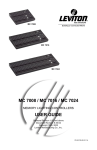
1
R
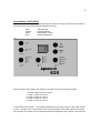
LP612 and LP624 User's Manual
Rev. 1.2
LP612 Software Version 1.1
LP624 Software Version 1.0
Leprecon/CAE, Inc
P.O. Box 430, 10087 Industrial Drive, Hamburg, MI 48139-0430 810-231-9373, FAX 810-231-1631
Copyright CAE, Inc. January 1997, Publication # 21-2125C
1
EZ PROGRAMMING THE LP-600 SERIES
Programming Preset Memories................................................
1.
2.
3.
4.
5.
6.
Press the "Preset" menu to light the "Page" LED
Select desired page (1-4) using display "Up" or "Down" arrows
Press "Record" button
Set desired look by arranging X scene channel faders
Store by pressing bump button beneath desired preset fader
on Y scene, continue setting and recording
Press "Run" to play scenes back
Programming a Chase...............................................................
1.
2.
3.
4.
5.
6.
7.
Press "Chase" button to light "Pattern" LED
Select desired pattern (5-11) on display using "Up" arrow
Press "Chase" menu button again to light "Step" LED
Press "Record" button
Set desired look on X scene faders
Press the display "Up" key to record & advance to next step, continue to set and
record chases
Press "Run" key to end programming
To Record Stack Presets............................................................
1.
2.
3.
4.
5.
6.
7.
8.
9.
10.
Press the "Stack" menu button to display ‘now’ scene.
Use the "Down" key to set now to ‘—’(CL may momentarily appear).
Press the "Stack" menu key again to light the "next" Led.
Use the display up and down keys to select a cue number of 1 through 50.
Set levels on stage using manual channels or Presets.
Press the "Record" key once. The "Record" Led will begin to blink.
Press "Record" again to memorize the cue. The next cue number will
advance.
In record mode, continue setting desired levels on stage and
recording cues (stacking).
Press "Run" to end recording and activate "Cue Stack".
While in "next" mode use display Up and Down keys to call up
first cue for playback.
Use "Stack" fader to manually crossfade between cues or use GO
button to time fade to next cue.
2
SETUP ............................................................................................................................................................4
POWER REQUIREMENTS ....................................................................................................................................4
MICROPLEX OUTPUT ........................................................................................................................................4
DMX OUTPUT ..................................................................................................................................................4
ANALOG OUTPUT .............................................................................................................................................5
CONNECTOR PIN ASSIGNMENTS : LP612 ONLY..............................................................................................5
CONNECTOR PIN ASSIGNMENTS : LP624 ONLY..............................................................................................6
CONTROL LAYOUT ...................................................................................................................................7
STARTUP.......................................................................................................................................................8
MANUAL MODE..........................................................................................................................................9
X AND Y PRESET SCENES.................................................................................................................................9
CROSSFADER ....................................................................................................................................................9
MASTER .........................................................................................................................................................10
BUMP BUTTONS .............................................................................................................................................10
RUNNING IN MANUAL MODE .........................................................................................................................12
PATCHING DIMMERS: .....................................................................................................................................13
USING MEMORY PRESETS....................................................................................................................14
CLEARING MEMORY .......................................................................................................................................14
PRESET MENU: LP612 ONLY .......................................................................................................................16
PRESET MENU: LP624 ONLY .......................................................................................................................17
PAGE FREEZE .................................................................................................................................................18
RECORDING PRESETS INTO MEMORY .............................................................................................................18
PRESET PLAYBACK .........................................................................................................................................20
PREVIEWING PRESETS ....................................................................................................................................20
EDITING PRESETS ...........................................................................................................................................21
CUE STACK ................................................................................................................................................21
RECORDING STACK SCENES ...........................................................................................................................23
ASSIGNING FADE TIMES .................................................................................................................................24
DEFAULT FADE TIME.......................................................................................................................................25
STACK PLAYBACK ..........................................................................................................................................25
EDITING CUES ................................................................................................................................................26
CHASE .........................................................................................................................................................27
PATTERN ........................................................................................................................................................27
STEP ...............................................................................................................................................................27
RATE ..............................................................................................................................................................27
PRE-PROGRAMMED CHASES ...........................................................................................................................28
RECORDING NEW CHASES ..............................................................................................................................28
LEVEL CHASES: LP624 ONLY ........................................................................................................................29
PATTERN EDIT ................................................................................................................................................29
STEP EDIT .......................................................................................................................................................29
REPAIR AND WARRANTY INFORMATION .......................................................................................30
3
Overview
The LP612 and LP624 were designed with the goal of creating low-cost, high quality control
consoles. The LP600 series boards share many features with the larger Leprecon LP1500
consoles, but brings these features within reach of users with a smaller budget. Some of these
features are:
Manual scenes
Two scene manual presets. Switchable Add or Solo momentary buttons for each channel. Dipless
crossfade between manual scenes. Each channel has a large, easily visible Led indicator.
Preset Memories
Real-time preset faders with switchable Add or Solo bumps. Presets may be "piled on" in any
combination. Presets are assigned to one of four memory pages. Preview mode allows cues to be
checked without bringing up the scene on stage. An existing cue may easily be edited using the
manual scene faders without re-recording the entire cue.
Cue Stack
50 programmable cues with crossfader and go button control. Fade times can be assigned to
each scene. A two character display is used to indicate current and next cues, and programmed
fade time.
Chaser
Four fixed and seven programmable patterns of up to twenty-four steps each are provided.
Programmable patterns are recorded, previewed and edited as easily as the preset cues. The rate
of each pattern may be saved with the Chase, eliminating the need to adjust the rate pot when the
Chase is recalled. The Chase may be advanced a step at a time manually, or halted momentarily.
Output
Standard output is industry standard Microplex using a three pin XLR connector. The optional
DMX 512 output uses the standard 5 pin XLR as specified by USITT, and the analog option uses
Cinch-Jones connectors common on other Leprecon equipment.
All output protocols can be used simultaneously.
Model Designations
The LP600 series consists of two consoles; the LP612 and the LP624. As the controls of both
consoles are very similar, the designation LP600 is used to describe common features. The
sections of this manual specific to either board are marked as “LP612 Only” or “LP624 Only”.
4
Setup
The LP600 connects easily to most types of dimming systems. Microplex, as well as the optional
analog and DMX 512 outputs are provided for dimmer control. The flexibility to interface to various
systems makes the LP600 a natural choice for building a new system, or upgrading an existing
system.
Power requirements
The LP600 console can be powered in two ways.
a) With Microplex dimmers, the microphone cable between the dimmer and controller supplies
board power. No external supply connection is required.
b) With DMX and analog options, an external supply must be used to power the board. This
transformer is supplied as part of the option package. This transformer is rated for 12VAC at 800
milliamps.
If the board is to be used with European power systems, or other 230 volt applications, contact
your Leprecon dealer for the correct 230 volt power supply.
Microplex Output
The three pin XLR connectors at the back of the LP600 are used to connect the board to standard
Microplex dimmers. This connection will work with Leprecon 360 Microplex dimmers, and has
been tested with other products for compatibility.
Microplex is suitable for use in smaller systems, up to 64 channels. Ordinary microphone cable
may be used to connect the LP600 to Microplex dimmers.
DMX Output
The DMX 512 digital output on the rear panel offers a fast and reliable way of sending control
information to the stage. Simply connect a 5-wire DMX control cable from the console output to
the DMX input on the dimmer. As the standard mandates, the LP600 has a 5 pin XLR female
connector. Additional dimmers can be "daisy-chained" from the first dimmer, by running additional
cables between the dimmers.
DMX512 uses a high speed digital signal, and the correct cable type is essential for reliable
operation. Microphone cable is not DMX cable. Use of microphone cable for DMX 512 is not
recommended.
The LP600 has been tested and complies fully with the USITT DMX 512/1990 standard, and
should pose no compatibility problems with any DMX 512 dimmers from Leprecon or from other
manufacturers. Should any suspected incompatibilities be encountered, please contact your
Leprecon dealer with the specific dimmer model and manufacturer.
5
Analog Output
Even with the advent of digital control standards, many portable lighting systems use analog
control lines between the console and the dimmer racks. The LP600 provides 0-10 volt analog
outputs, using Cinch-Jones connectors. The pin connection of these connectors is identical to that
used on many other Leprecon products.
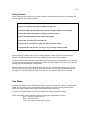
Connector Pin Assignments : LP612 ONLY
The analog version of the LP612 uses two panel mount male Cinch-Jones 8 pin connectors for
control output. The pin connections are as follows:
1
2
8
8
1
1
Connector 1
Pin
1
2
3
4
5
6
7
8
Function
Channel 1
Channel 2
Channel 3
Channel 4
Channel 5
Channel 6
No connect
Common
Connector 2
Pin
1
2
3
4
5
6
7
8
Function
Channel 7
Channel 8
Channel 9
Channel 10
Channel 11
Channel 12
No connect
Common
6
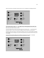
Connector Pin Assignments : LP624 ONLY
The analog version of the LP624 uses one panel mount male Cinch-Jones 27 pin connector for
control output. The pin connections are as follows:
1
27
Pin
1-24
25
26,27
Function
Channel 1-24
No connection
Common
7
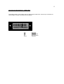
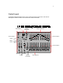
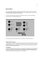
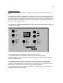
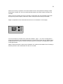
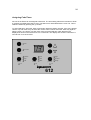
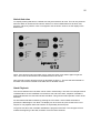
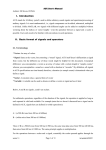
Control Layout
The diagram below illustrates some of the controls that will be referenced in this manual.
Although the LP612 is shown, the controls of the LP624 are similar.
D
Display
Up & Down
LED Display
run
Output Indicators
1
record
Menu Buttons
chase
on
Chase
now
next
stack
on
time
preset
on
5
6
7
8
9
10
11
12
10
10
10
10
8
8
8
8
8
6
6
6
6
6
6
bump
4
4
4
4
4
4
2
2
2
2
2
2
0
0
0
0
0
0
x
y
10
10
0
10
10
10
10
10
10
8
8
2
8
8
8
8
8
8
6
6
4
6
6
6
6
6
6
4
4
6
4
4
4
4
4
4
2
2
8
2
2
2
2
2
2
0
0
10
0
0
0
0
0
chase
Preset
4
10
8
612
Stack
3
page
preview
mode
pattern
step
rate
2
10
stack
master
1
go
tap
Tap Button
2
3
4
5
6
manual
crossfade
Go Button
Master
Manual
Crossfader
Bump Buttons
7
8
9
0
10
11
12
x
X Scene Faders
y
Y Scene Faders
8
Startup
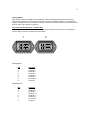
The console will perform a brief test when power is applied. If the board fails power-on testing, the
display will show:
Any error message indicates problems that must be repaired. Some errors may leave the LP600
functional in manual mode only.
9
Manual Mode
The LP600, in addition to being a powerful memory console, can also be used as a simple twoscene preset board. This allows an untrained operator to immediately start using the board, and
learn it's more advanced features as time permits.
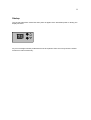
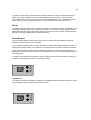
To set the LP600 to manual mode, press the 'preset' menu button. The 'page' Led will light.
Press the 'down' arrow until the display shows:
run
record
m o de
ch ase
on
pattern
step
rate
stack
on
now
page
next
time
preview
bump
preset
on
612
This indicates that the preset memories are off. The 'preset on' Led will be turned off.
X and Y Preset Scenes
The most basic control of the LP600 console is provided by the rows of faders for the two manual
scenes, labeled "X" and "Y." Each X and Y pair of faders controls a single console channel, which
may be connected to one or more dimmer channels. The green output Led above each channel
indicates the channel's relative intensity.
Crossfader
The Manual Crossfader, just to the left of the Y scene faders, is used to fade from the top manual
(X) scene to the lower(Y) manual scene. With the fader at the top position, the board output will
be set by the levels on the X scene faders. If the crossfader is moved to the bottom position, the
levels on stage will be set by the position of the Y scene faders.
10
Typically, a scene might be set up with the X channel faders in advance, and when that cue is
called, the manual crossfader is moved upward together to the X position. This leaves the Y
scene available to be set up for the next cue. At the appropriate time, the Crossfader is pulled
down to the Y position, and the now inactive X scene available to be set for the next cue.
Master
The Master fader is used to set an overall output level for most board controls. The Master can be
used to fade out all scenes of the console for a blackout. The only controls that operate with the
Master down are the bump buttons and Chaser. No output from the Cue Stack, Preset scenes or
Manual scenes are possible with the master level down.
Bump Buttons
The momentary switches located below the lower scene faders can have different functions
depending on the current mode of operation.
The normal RUN mode function of these switches is to momentarily flash a channel or scene on
stage without using the fader. The channel or scene drops back out when the button is released.
When cues are being programmed and edited, these buttons are used to select memories for
modification. Therefore, when the Record or Edit modes are active, the momentaries DO NOT act
as bump buttons.
To display and change the bump button modes, press the 'preset' menu key until the 'bump' Led
is lighted. The display will show one of 5 possible modes:
1) Bumps Off
This display indicates the bumps are disabled. No possibility exists of flashing a channel or scene
by accidentally pressing a button while running a show.
11
2) Channel Add
Channel Add is the simplest mode of bump operation; pressing a bump button will bring the
channel up on stage for as long as the button is pressed without affecting any other channels.
3) Channel Solo
When Solo mode is selected, pressing a bump button will black out any other channels that are
up, and bring the selected channel to 100% output. As with bringing down the Grand Master
manually, any output from the Chaser will be unaffected by a Solo button being pressed.
The last two bump modes are available only when preset memories are active.
4) Preset Add
When preset memories are active, the lower scene faders are being used as Preset Masters. In
this case, the Y scene faders no longer control single channels, but entire memory scenes. The
bump buttons can be used to flash the memorized scene. The Channel Add and Channel Solo
settings can still be used to bring up a single channel, even though the fader controls an entire
scene.
For more information, see “Using Memory Presets”.
5) Preset Solo
The Preset Solo mode flashes a memorized preset scene on stage, while blacking out any other
channels or scenes. The effect is the same as bringing down the master fader momentarily while
pressing a bump button. The Chase and any other bumps are the only area of the board not
affected by a Solo bump.
12
Running in Manual Mode
1. Set all X and Y channel faders, and the PRESET master fader to zero.
2. Set the manual crossfader fully downward, to the Y scene position.
3. Bring the MASTER fader up to full. No stage lights will be on.
4. Set up the first scene on the X channel faders.
5. Push the manual crossfader up to the X position, and the X scene will light the
stage.
6. Set up the next scene on the inactive Y channel faders.
7. Crossfade to the Y scene by moving the manual crossfader to the Y position.
7. Continue to set up subsequent scenes in this manner; alternating between the X
and the Y groups.
13
Patching Dimmers:
The LP600 series allows for a default 1:1 patch to be used, or a custom dimmer patch can be
built.
The custom patch allows the assignment of any dimmer circuit to a specific board channel. Up to
96 DMX dimmer channels, 48 Microplex and 24 analog channels can be patched. More than one
dimmer circuit may be assigned to a single board channel; in other words, the channel 8 fader on
the console might bring up dimmer circuits 8, 16, and 32. However, a single dimmer circuit can be
patched to only one board channel.
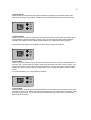
To set the patch, press the button labeled "preset” below the numeric display until the yellow Led
labeled ‘patch’ is lighted:
page
run
record
m ode
chase
on
pattern
step
rate
now
stack
on
next
time
preset
on
page
preview
bump
patch
624
The ‘dF’ display indicates the default, or straight 1:1 patch is in effect.
To switch the board to the custom patch, press the UP arrow next to the display.
The 2 digit display now shows the active dimmer number. The active dimmer can be changed
with the UP and DN arrows.
The channel assigned to the active dimmer channel is indicated by the output Led indicator
located above each board channel. To assign the active dimmer channel to another board
channel, press the bump button of the new channel. The Led for the previously assigned board
channel will go out, and the Led for the new board channel will be lighted.
To clear a dimmer assignment, press the bump button of the lighted channel. The bump button
will toggle the channel to an ‘off’ state.
14
To erase the Custom Patch:
1) Press the Preset menu button in the upper left corner of the board. Repeat key press until the
"patch" Led is lighted.
2) Press the "down" arrow until the label "CL", indicating CLear, appears on the display. The red
record Led will begin to blink.
3) While the Led is blinking, press the "record" key.
4) While the display is blinking, press 'record' again to clear all presets.
5) The board will verify the operation by displaying “dE” (default
Erase) for a few seconds. The custom patch will now be initialized to a 1:1 patch for 24 dimmers.
Using Memory Presets
The LP600 is much more than a two scene preset board. The lower scene of faders can be
converted to individual memory preset masters. This is indicated by the 'preset on' Led being
lighted. These presets operate in a "pile-on" mode, allowing more than one preset to be up at any
one time.
Clearing Memory
Preset scenes, Stack cues, and Chases recorded into the LP600 are stored in non-volatile
memory. This memory system uses no battery, eliminating the need for checking and replacing
backup batteries.
When starting to program a new show, it is easier to start with an empty board. The Erase
function in the LP600 can be used to delete all scenes, cues, and Chases, leaving the scenes
empty and ready to program.
To erase Preset scenes in the LP600:
1) Press the Preset menu button in the upper left corner of the board. Repeat key press until the
"page" Led is lighted.
2) Press the "down" arrow until the label "CL", indicating CLear, appears on the display. The red
record Led will begin to blink.
3) While the Led is blinking, press the "record" key.
4) While the display is blinking, press 'record' again to clear all presets.
5) The LP600 will verify the operation by displaying “PE” (Preset Erase) for a few seconds.
To erase Stack Cues in the LP600:
15
1) Press the "stack" menu button in the upper left corner of the board. Repeat key press until the
"now" Led is lighted.
2) Press the "down" arrow until the label "CL", indicating CLear, appears on the display. The red
record Led will begin to blink.
3) While the Led is blinking, press the "record" key.
4) While the display is blinking, press 'record' again to clear all presets.
5) The LP600 will verify the operation by displaying “SE” (Stack Erase) for a few seconds.
To erase Chases in the LP600:
1) Press the "Chase" menu button in the upper left corner of the board. Repeat key press until the
"pattern" Led is lighted.
2) Press the "down" arrow until the label "CL", indicating CLear, appears on the display. The red
record Led will begin to blink.
3) While the Led is blinking, press the "record" key.
4) While the display is blinking, press 'record' again to clear all presets.
5) The LP600 will verify the operation by displaying “CE” (Chase Erase) for a few seconds.
16
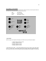
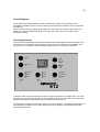
Preset Menu: LP612 ONLY
The Preset functions are controlled by pressing the 'preset' menu key on the front panel. When in
the Preset mode, this button switches between three items:
page
preview
bump
Page Number
Preview and Edit
Bump Button control
run
record
m o de
ch ase
on
pattern
step
rate
now
stack
on
next
time
preset
on
page
preview
bump
612
Page Number
When the 'page' Led is lighted, the display up and down keys cycle through the pages:
"--" Manual mode, preset on Led off
" 1" Page 1, preset on Led on
" 2" Page 2, preset on Led on
" 3" Page 3, preset on Led on
" 4" Page 4, preset on Led on
In the Manual mode ( page "--") the LP612 operates as a two scene console. If the page number
is set to 1 or higher, the Y scene faders act as memory presets. Each page represents an entire
set of presets; the LP612 can store 48 preset memories organized as four pages of 12 memories.
17
Preset Menu: LP624 ONLY
The Preset functions are controlled by pressing the 'preset' menu key on the front panel. When in
the Preset mode, this button switches between four items:
page
preview
bump
patch
Page Number
Preview and Edit
Bump Button control
Dimmer assignment
page
run
record
m o de
ch ase
on
pattern
step
rate
now
stack
on
next
time
preset
on
page
preview
bump
patch
624
When the 'page' Led is lighted, the display up and down keys cycle through the pages:
"--" Manual mode, preset on Led off
" 1" Page 1, preset on Led on
" 2" Page 2, preset on Led on
" 3" Page 3, preset on Led on
" 4" Page 4, preset on Led on
In the Manual mode ( page "--") the LP624 operates as a two scene console. If the page number
is set to 1 or higher, the Y scene faders act as memory presets. Each page represents an entire
set of presets; the LP624 can store 96 preset memories organized as four pages of 24 memories.
18
Page Freeze
When the page number is changed, the presets are assigned a new set of memories. To prevent
sudden changes on stage, any fader which is up ( above 1 on the scale) maintains its current
‘look’ or memory scene. The fader will hold its scene until it is brought down to zero. At that time, it
is then assigned a scene on the new page.
This page freeze method is also used when switching between manual mode and the memory
presets mode. If a Y scene fader is up when the page number is switched from manual ("--") to
page 1, the fader remains a channel in the Y scene until it is brought down. Once the fader is
down, the fader is then assigned a memory preset scene in page 1. If a fader is assigned a
memory preset scene and the fader is up, it keeps the preset scene up even when the page
number is changed to manual mode ("--"). Only when the fader is brought down to zero does it
revert to a channel in the Y scene.
Recording Presets Into Memory
Recording presets on the LP600 is quick and simple. Presets are always recorded from the
console's current output. In other words, the levels of all lights, whether they are controlled from
the X scene, another preset, the Cue Stack or any combination of these, can be recorded as the
new preset. In general, what you see on stage is what you will get as a memory. Thus, when the
master fader is at maximum, raising a particular preset fader to maximum will reproduce the exact
output of the console at the moment that preset was recorded.
To record scenes into memory presets:
1) Press the presets menu key to light the 'page' Led.
2) Use the display up and down keys to select a page number of 1 through 4.
3) Place the console in Record mode by pressing the record button.
4) Set the stage look using the X scene channel faders.
5) Press the bump button beneath the desired preset fader.
6) When finished recording, press the 'run' key.
19
When the record key is pressed, the Led’s located next to the bump buttons will begin to flash
along with the record Led. This is to indicate that the buttons are ready to select a preset to be
recorded.
When a bump is pressed, the scene is recorded. The preview Led is lit momentarily (along with
the page Led), and the display verifies the number of the preset which was just recorded.
Illegal or impossible record commands will result in an error indication on the display:
If the record button is pressed when presets are disabled (page -- ), the error message will be
momentarily displayed. If the selected preset was in "Page-Freeze" mode, then the display shows
a flashing error for a couple of seconds, and the preset is not recorded. The display then reverts
to the page number.
While in the Record mode, scenes may be entered in any order into the LP600. Once recording is
finished, press the "Run" mode button to return to run mode.
20
Preset Playback
Once scenes have been recorded into the Preset Memory faders on the LP600, they are
immediately available for use. It is not necessary to leave the record mode to check or playback
the memory.
With the master fully up, bringing up the fader for a memory scene will output the scene to the
stage. Any number of faders can be up at one time, the scenes 'pile on' in a higher takes
precedence fashion.
Previewing Presets
From the preset page display, pressing the Presets menu button again will set the console to the
Preview mode. This will be indicated by the 'preview' Led. The preview mode is available only if
the 'preset on' Led is lighted, which indicates a page number of 1 through 4 is selected.
run
record
m o de
ch ase
on
pattern
step
rate
now
stack
on
next
time
preset
on
page
preview
bump
612
In Preview mode, the green output level Led’s no longer represent the on-stage levels. The Led’s
now show the channel levels as stored in the selected preset scene. The Led’s next to the bump
buttons are steadily lit, indicating the bumps function as presets selects.
The first time this mode is entered after startup, the preset number 1 is selected. This number can
be changed by pressing the up or down arrow keys or by pressing the bump button below the
preset to be previewed.
21
Editing Presets
Single channel level changes can be quickly made to a selected preset. The X scene faders are
used to adjust levels within the preset.
To Edit presets:
1) Press the 'preset' menu key to light the 'page' Led.
2) Use the display up and down keys to select a page number of 1 through 4.
3) Press the 'preset' key again to change to preview mode.
4) Press the bump button of the scene to be edited.
5) Press the 'record' key to start the edit.
6) Use the X scene faders to 'grab' and adjust channel levels.
7) Conclude the edit with the 'run' key, or by selecting another preset.
During an edit, the Select Led’s next to the bump buttons, as well as the 'record' Led will be
lighted. This indicates that the buttons are available to select presets to be edited.
To edit a channel, first move the channel fader to the approximate level indicated on the Led. This
will 'grab' the channel and the Led will begin to follow the fader position. Any number of channels
in the preset may be adjusted in this fashion.
When all channels have been adjusted, press the 'run' key to save the modified preset. To edit
several scenes in a row, press another bump button for the next preset to be edited instead of
pressing 'run'. This will save the results of the first edit, and start the edit of the next preset.
Cue Stack
The Cue Stack feature of the LP600 offers many of the features that are useful in a small theatre
board. Up to 50 cues can be programmed and played back in sequence with perfectly timed
fades. Recording, editing and running the Cue Stack is quick and easy.
To use the Crossfade Stack, first press the 'stack' menu button below the display.
When in the Stack mode, this button switches among the 3 parameters or items:
Now - The Now (current) scene
Next - The Next scene
Time - The Fade time from Now to Next
22
When the 'stack' key is pressed for the first time, the 'now' Led will light. The display will show:
run
record
m o de
chase
on
pattern
step
rate
now
stack
on
next
time
preset
on
page
preview
bump
612
This indicates that the current stack cue is blank, and no output is present from the stack. The
scene number which is below 1, "--", is the blackout scene. This blank scene can be set for the
Next scene, and a fade to black will result.
In the case where both the Now scene and the Next scene are set to off, "--", the stack output is
off and the 'stack on' Led is off. The stack crossfader and the GO button are now ignored.
Pressing the stack menu button a second time will light the 'next' Led, and the display will indicate
the cue ready to fade. Pressing the 'up' and 'down keys allow any of the 50 scenes to be set in the
'next' display:
The Crossfade from Now to Next can be started by pressing the "Go" button, or controlled
manually by moving the stack fader from one end of it's travel to the other.
run
record
m ode
pattern
ch a se
on
step
rate
page
now
next
stack
on
time
preset
on
612
preview
bump
23
Recording Stack Scenes
Recording into the Stack places a stage look in the cue selected as 'next'. In the example, this
would be Cue #1. To select another cue, use the display up and down keys.
Set up the stage look by using the X channel faders or any available presets. Press the 'record'
button. The red Led next to the switch, will begin to blink.
Cues can be entered in sequence simply by setting scenes and pressing the 'record' button to
record each cue. At any time, any cue number from 1 to 50 can be set and recorded. The
sequence will advance from that point. For example, 'next' could be set to 10 This would be done
by pressing the display up key until the number "10" appears on the display. The next time 'record'
is pressed, Cue #10 will be recorded. The Cue number will automatically advance, and the next
cue would be 11.
When recording is finished, return to Run mode by pressing the "Run" button. The Record and
Select Led’s will stop flashing and the bump buttons will return to normal operation.
To record Stack Presets:
1) Press the 'stack' menu button to display 'now' scene.
Use the 'down' key to set now to '--'
2) Press the 'stack' menu key again to light the 'next'Led.
3) Use the display up and down keys to select a cue number of 1 through 50.
4) Set levels on stage using manual channels or Presets.
5) Press the 'record' key once. The 'record'Led will begin to blink.
6) Press 'record' again to memorize the cue. The 'next' cue number will advance.
7) Continue setting and recording cues.
8) Press 'run' to end recording.
24
Assigning Fade Times
All cues in the Stack can be assigned a fade time. The time setting reflects the total time to finish
a complete crossfade from Now to Next. The fade time is associated with the 'next' cue. Timed
fades are started by pressing the 'go' button.
To enter fade times, press the 'stack' menu button below the display until the ‘next’ Led is lighted.
Use the ‘up’ and ‘down” keys to select the correct scene number. Press the ‘stack’ key again to
light the ‘time’ Led. Use the ‘up’ and ‘down’ keys to set the fade time. Note that times are
displayed in tenths of seconds from 0.0 to 9.9 seconds The display then shows increments of 1
second from 10 to 59 seconds.
run
rec ord
m o de
c h ase
on
pattern
now
page
step
next
preview
rate
time
stack
on
p reset
on
612
bump
25
Default fade time
To simplify entering fade times, a default time may be entered for all cues. This can only be done
when the Stack is cleared and all cues are erased. To select a default time for all stack cues,
press the ‘stack’ key until the ‘next’ Led is lighted. Use the ‘down’ arrow to set the display to the
blank scene:
run
rec ord
m o de
c h ase
on
pattern
now
page
step
next
preview
rate
stack
on
time
p reset
bump
on
612
When ‘next’ has been set to the blank scene, press the ‘stack’ menu button again to light the
‘time’ Led. Enter the time desired as the default time for all scenes.
Now proceed to erase all stack scenes as described on page 11. The time that was entered for
the blank scene will be inserted as the fade time for all stack scenes.
Stack Playback
The cues recorded in the Cue Stack can be used in several ways. The first is as a simple manual
crossfade stack. As the crossfader is moved from one end to the other, a dipless crossfade is
performed between the cues listed as Now and Next. This gives the board operator control of the
transition.
An automatic timed fade is started by pressing the "Go" button. At the instant the button is
pressed, the fade begins. The "Next" cue display can be re-set at any time to take cues out of
sequence. The playback order will continue on sequentially from that point.
The green Led above the crossfader indicated the progress of the fade. The Led pops to full to
indicate the beginning of the fade, and dims out as the fade continues.
26
When the scene number is changed from 1 with the DOWN button, the scene number displayed
goes to "--", and the stack output is then turned off. This is how the stack can be quickly removed
from the on-stage look.
Editing Cues
Once a Stack cue has been recorded, the level of a single channel in memory can be altered
without re-recording the entire cue. In the Edit mode, the faders of the top scene are used to
adjust the channel levels. The scene shown in the 'now' position on the display is the scene that
will be edited. This allows scenes to be modified as they are seen on stage.
To Edit Stack Cues:
1) Crossfade to the cue to be edited.
2) Press the 'stack' menu key to light the 'now' Led.
3) Press the 'record' key to start the edit.
4) Use the X scene faders to 'grab' and adjust channel levels.
5) Conclude the edit by pressing the 'run' key.
To enable editing the scenes in the Stack, the console must be placed into the Record mode and
the Stack menu button must be pressed to select the Now scene mode. The scene number set in
Now is the number of the scene being edited.
In edit mode, the output level Led’s are used to show the contents of the selected memory. The X
scene faders directly below the Led’s are used to adjust channel levels. The faders take control of
a channel when the fader position matches the level recorded into memory. The brightness of the
level Led and the value in the display will begin to change when the fader takes control of the
channel. For example, to edit a channel that was recorded at 100%, it would be necessary to bring
the top scene fader for that channel up to full to capture the channel, moving the fader down from
that point would reduce the level of the channel.
Any number of channels can be adjusted in one edit, using the X scene faders.
To edit a sequence of stack scenes as they are being played back, simply leave the console in the
Now mode. When a scene is encountered that needs editing, press the 'record' button. This
places the scene in the Edit mode and changes can then be made. The console may be left in
Edit mode while a series of scenes are played and edited. This is handy for rehearsal-type
changes.
27
Chase
The Chase functions are activated by pressing the 'Chase' menu key on the front panel. The
board will enter the Chase mode.
When in the Chase Menu mode, this button switches among the 3 parameters or items:
Pattern - The Chase pattern to be viewed
Step - The current step number
Rate - The current Chase rate
The Chaser level is controlled by the "Chase Level" fader. When the fader is down, the Chaser is
off. When the fader is brought up, the Chaser is started on the first step of the selected pattern.
Pattern
The first item in the Chase menu is the Chase Pattern mode. This is indicated by the 'pattern' Led
being lighted. The 2 digit display indicates the pattern number. This number can be changed using
the UP and DOWN buttons. Patterns 1 through 4 are pre-programmed Chases that cannot be
altered. Patterns 5 through 11 are custom patterns that must be recorded before use.
When the pattern number is changed to below 1, the display shows "--", and the Chaser is off and
disarmed.
When the pattern number is set to 1 or higher, the Chaser is on. When the Chase fader is brought
up, the Chaser starts running and the Chase appears on stage at the level of the fader. Each
pattern has up to 24 steps associated with it.
Step
Pressing the 'Chase' menu key a second time will light the 'step' Led and the display will show the
current step number of the selected Chase pattern. While the Chase is running, the number
moves at the rate recorded for the Chase. When the Chase is stopped, the number displayed is
the last step viewed before it was stopped.
Rate
The 'rate' mode displays the Chase rate in percent of full speed. The 'up' and 'down' buttons can
be pressed to increase or decrease the speed of the Chase. There are 100 accessible rates using
these buttons.
The Chase rate can also be set using the Chase 'tap' key. When a Chase is running, tapping the
tap button synchronizes the Chase rate with the tap.
Chase rate is saved with the Chase. When the Chase is recalled, the rate will automatically be
set.
28
Pre-programmed Chases
The standard Chases can be run immediately without recording steps, but cannot be altered.
These Chases are selected by setting the Chase pattern display to positions 1 through 4. The four
standard Chases have the following effects:
1) Straight
A single channel on, advancing sequentially from 1-2, 2-3, and so on until step 6 loops
back to channel 1.
2) Reverse
Same as Chase 1 except begins with channel 6, and proceeds to light lower channel
numbers until 1 is reached. The next step loops back to channel 6.
3) Zig-Zag
A ten step Chase that starts with only channel 1 up, and advances sequentially until
channel 6 is lighted. Step 7 starts the Chase back down from channel 6 to 5, and it
proceeds back down to channel 1, when the pattern repeats.
4) Straight 12 channel
Same as Chase 1 except advancing sequentially from 1 to 12, when the loop repeats.
Recording New Chases
The Chaser section of the LP600 allows for seven custom Chases to be programmed by the user.
Each of these patterns can consist of up to twenty-four steps, each consisting of any combination
of channels. These programmable Chases are available on patterns 5 through 11.
To record a custom Chase:
1) Set the pattern display to one of the patterns 5 to 11.
2) Move the 'Chase' fader to zero. The Chase cannot be running while steps are
recorded.
3) Press the 'Chase' menu button a second time to enter 'step' mode.
4) Press the 'record' button.
5) Set the channels of the Chase step using the bump buttons or X scene faders.
6) Press the 'up' key to advance to the next step.
7) When finished, press the 'run' key to end programming.
29
Level Chases: LP624 Only
The LP624 has provision for programming channel levels as Chase steps. This allows any value
between 0 and 100% to be programmed as a channel level instead of the on/off programming that
is used on the LP612.
The programming of levels is identical to the procedure outlined above for Chase recording. If the
bump buttons are used to set channel levels, the only values used will be off and on. If the X
scene faders are used, the level set with the fader is memorized into the Chase step.
Pattern Edit
When a custom Chase is entered in the LP600, a fixed length for that Chase is established.
Pattern edit allows the Chase steps to be altered without changing the length of the Chase.
Pattern edit only can be used for a Chase that has been already programmed as described
above.
During a pattern edit, the ‘tap’ button steps the Chaser to the next step without changing the
Chase length. The 'tap' button can be used to step through all the steps of the Chase pattern to
verify it is correct.
First, select the pattern to be changed. Press the ‘Chase’ menu key to light the ‘pattern’ Led. Use
the ‘up and ‘down’ keys to select the pattern. Press the ‘Chase’ menu key again to light the ‘step’
Led. The display will show the current step of the selected pattern.
Press the ‘record’ key to start the edit. In this mode, the Chaser is stopped regardless of the
recorded rate. The output Led’s will show the programmed channels of the indicated step. Use the
'tap' key to advance the Chase step by step. When a step is to be edited, use the bump buttons or
X scene faders to turn channels on or off..
Step edit
When the Chase pattern is 5 or higher and the Record mode is on, step editing allows changing
the number of steps in the selected pattern.
First select the pattern to be changed. Press the 'Chase' menu button to light the 'pattern' Led
then press the 'record' button. The pattern number must be set to 5 or higher.
Press the 'Chase' menu key a second time to show the current step number. The step number
can be changed using the 'up' and 'down' keys. As steps are added using the ‘up’ key, the
channels programmed into each step may be set using the bump buttons and faders.
The step number showing when the 'run' button is pressed becomes the new length of the Chase.
30
Repair and Warranty Information
CAE will repair any defects in materials or workmanship on the LP600 for a period of one year
from the date of sale. The equipment must be returned postpaid to the factory, and CAE will pay
return shipping charges. CAE is not responsible for incidental damages, or for damage as a
result of misuse or abuse. It is the responsibility of the owner to determine the suitability of the
console for any specific application.
Any return to the factory must be authorized by our service department. Do not return any
equipment without first calling for an authorization number. The CAE service department may be
reached at 810 231 9373 during business hours, or a message may be left after hours. Our fax
number is 810 231 1631.
CAE, Inc.
PO Box 430
10087 Industrial Drive
Hamburg, MI 48139