1
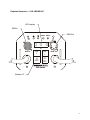
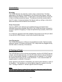
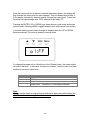
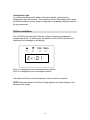
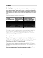
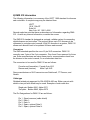
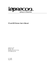
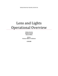
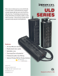
ULD-360DMX and ULD-360DMX-HP
USER’S MANUAL
©Copyright Leprecon LLC. 2005
All rights reserved
Publication 21-1045 Rev C
This document is the property of Leprecon LLC, and is provided for service and instructional purposes
only. Possession does not imply or convey rights to use any information herein. This information is
proprietary, and may relate to patents or patents pending that are the properties of CAE, Inc. other than
the use of products manufactured by CAE, Inc.
1
Table of Contents
Endplate Illustration – ULD-360DMX-HP ........................................................... 3
1) Introduction .......................................................................................................... 4
2) Specifications........................................................................................................ 4
Power Connection .................................................................................................. 4
Ambient Temperature............................................................................................. 4
Power Capacity ...................................................................................................... 4
Control input .......................................................................................................... 5
3) Installation ............................................................................................................ 6
Mounting ................................................................................................................ 6
Power Connection .................................................................................................. 6
Load Connection .................................................................................................... 6
4) Turning on Power ................................................................................................. 6
5) Front Panel Controls............................................................................................. 7
Resetting the ULD-360 to default values: ............................................................. 7
Channel Mode Menu.............................................................................................. 8
Status Menu............................................................................................................ 9
Configuration Data............................................................................................... 11
6) Error conditions .................................................................................................. 11
7) Service ................................................................................................................ 12
Service policy....................................................................................................... 12
Warranty Information........................................................................................... 12
8) DMX 512 Information........................................................................................ 13
Connectors............................................................................................................ 13
Cable type............................................................................................................. 13
2
Endplate Illustration – ULD-360DMX-HP
LED display
DMX In
DMX Out
Enter Menu
d 0 0
Data In
ON
I
ON
I
O
OFF
O
OFF
Line A
Data Out
Line B
ULD Series
Breaker ‘A”
3
1) Introduction
The new ULD series dimmer is designed to be a capable and reliable solution for
temporary and portable dimming requirements. With the menu-based interface,
the dimmer can be configured for different applications, including stand-alone
use without a controller. Default values can be restored at any time, clearing the
internal memory back to the standard values.
Please take a few minutes to review the specifications and operating features of
the ULD-360 dimmer.
The ULD-360 dimmer is designed for use with conventional incandescent
fixtures. Transformer loads, such as low voltage devices using a step-down
transformer, may require an additional load to be connected to the same circuit
to operate properly.
For operating florescent fixtures, see the section regarding Front Panel Controls.
2) Specifications
Power Connection
Unless otherwise indicated, your ULD-360 dimmer is designed for connection to
standard US power systems, 120 VAC 60 Hz. Lamp connections must be 120 V
devices only. Line voltages over 135 VAC will trigger the overvoltage protection
circuit and shut off the dimmer pack.
Ambient Temperature
The ULD-360 dimmer is designed for use in a cool, ventilated area. Ambient air
temperature must be less than 40 degrees Celsius, or about 104 degrees
Fahrenheit
Power Capacity
The ULD360 DMX is unique in the market of small portable dimmers. A single
breaker is used on the pack instead of individual fuses per each channel. As a
result, the limits of the dimmer are pack limits, not channel limits. The following
guidelines should be followed:
ULD-360 DMX
Pack Limit: 15 Amps
ULD360 DMX-HP
Pack Limit: 15 Amps per line cord, or 30 amps total
-4-
Control input
The ULD-360 DMX accepts DMX 512 1990 as specified by USITT. Reliable DMX
systems require cable rated for data communication at 250K baud; for this reason the
use of microphone cable is NOT recommended. DMX rated cables are available premanufactured from your Leprecon dealer. For more information on the DMX standard
and acceptable cable, see the Appendix at the end of this manual.
For convenience, DMX in and out connectors are provided on the ULD-360DMX. This
allows easy connection to additional dimmer packs. The DMX standard allows up to 32
dimmers to be connected to a single DMX controller.
For proper operation, it is recommended that the last dimmer in the system have a
termination plug placed in the DMX Out connector. Termination plugs can be
purchased, or easily built by installing a 120 ohm resistor between pins 2 and 3 of the 5
pin XLR.
-5-
3) Installation
Mounting
The LD360 dimmers are passively cooled, using no internal fans. The heat
generated by the dimmer is dissipated by the extruded metal chassis, and the
airflow through the chassis vents. For this reason, mount the dimmer so that air
is free to circulate around the dimmer. The dimmer should be mounted with at
least 12 inches of clearance between the dimmer and any ceiling or obstruction
above the dimmer that would block air circulation.
Power Connection
Leprecon LD360 series dimmers are supplied with line cords which have
standard Edison plugs attached. Each line of the LD360 should be connected to
a service capable of supplying 15 amps and protected by a properly sized circuit
breaker.
If you have any questions about the suitability of the power circuit that you intend
to use with the LD360 dimmer, consult with a qualified electrician.
Load Connection
The LD360 DMX dimmer is offered in several different models. Options include
stage pin, Nema 5-15 duplex, and Nema L5-20. Lamp loads are plugged directly
into the outlets on the body of the dimmer.
4) Turning on Power
The ULD-360 has one line cord and circuit breaker, and the ULD-360HP has two
of each, as illustrated previously. On the HP model, the line cord and breaker to
the left on the endplate, labeled ‘A’, supplies power for channels 1-3, as well as
the internal power supply for the control electronics. Line cord and breaker ‘B’
supplies power to channels 3 through 6.
Power applied to the dimmer is indicated by an internal green indicator in each of
the breakers. If the breaker is on, but not lighted, there is no power to the line
cord. Turning on breaker ‘A’ will also light the red LED display.
Note:
The unit can be Reset to original factory settings by depressing and holding the
ENTER switch while turning on the first breaker.
-6-
5) Front Panel Controls
The ULD-360 dimmer uses a 4 digit display and four entry switches to set pack
functions, and display operating status.
Resetting the ULD-360 to default values:
The unit can be Reset to original factory settings by depressing and holding the
ENTER switch while turning on the first breaker.
ddress Menu
When the dimmer is first turned on, the display shows the starting channel
address of the ULD-360. This is the DMX address that will control the first
channel of the pack.
When there is no DMX input, the channel number is preceded by the letter A for
address:
A.004
When valid DMX is detected, the letter ‘A’ is replaced with the letter ‘d’ for DMX:
d.004
-7-
The UP/DOWN keys change the value for the start address. The ULD-360 uses
the changed value immediately and permanently saves it after 10 seconds or if
the Enter or Menu key is pressed.
After power on, the ULD-360 remains in the Address Menu in its simple interface
mode. To go to any other menu requires the user to hold the MENU key for about
5 seconds.
Channel Mode Menu
The Channel Mode Menu allows setting the mode of each dimmer channel.
This mode is indicated by the letter ‘c’ in the display:
c2:Ln
Set the mode for the displayed channel by pressing the UP/DOWN keys. The
possible channel modes are:
Mode
Ln
Nd
FL
00-FF
Description
Linear output. Standard dimmer channel.
Non- dim. Fader input above 60% turns on channel to 100%. Input
below 40% turns off channel.
Florescent output. Dimmer does not begin to turn on until 20%.
Fixed output level. Values are 0, 10-99 and FF. FF is 100% output.
After changing the mode the colon will blink to indicate new data has been
entered. Press the ENTER key saves the change, and advance to the next
channel.
The LD-360 returns to the Address Menu automatically after 4 seconds if no
keys are pressed in the Mode Menu.
-8-
Status Menu
When the ULD-360 is in the Channel mode, pressing ‘MENU’ again will start the
Status mode. When Status mode starts, the state of each channel will be shown
in sequence, with the display cycling from Channel 1 to Channel 6, then
automatically cycle back to channel 1. This automatic cycling is indicated by the
flashing colon.
The Status Mode first displays the current input state of the dimmer channels 16. If valid DMX is present, the letter ‘d’ is displayed, followed by the DMX value
for the channel:
d1:00
If there is no DMX present, the ‘d’ letter will disappear, and a ‘-‘ will be shown
instead:
-1:00
-9-
Once the input levels for all dimmer channels have been shown, the display will
then indicate the output level for each channel. This is indicated by the letter ‘o’
in the display, followed by channel number, followed by output level. Output will
be shown as a percentage, with 100% indicated b the letters ‘FF’
Pressing the ENTER, UP or DOWN keys stops the auto cycle mode and enters
manual mode. Pressing MENU toggles between auto and manual cycle modes.
In manual mode the menu steps through its displays when the UP or DOWN
keys are pressed. The colon is steady in manual mode.
d1:00
o1:FF
If a channel has been set to a fixed level in the Channel menu, the output status
will reflect that level. In this case, the input for channel 1 could be zero, but there
could be a non-zero output level.
Status Letter
–
d
o
F
Description
No input detected
DMX is input source
Output level
Output Fault – Overtemp or Overvoltage shutdown
Note:
The unit can be Reset to original factory settings by depressing and holding the
ENTER switch while turning on the first breaker.
- 10 -
Configuration Data
If you press the Menu button while in the status display, various factory
configuration data will be seen. These features are not fully defined at this point,
but include software version, power configuration, and analog calibration data for
the microprocessor.
6) Error conditions
The ULD-360 will protect itself if the line voltage or operating temperature
exceeds safe limits. In these cases, the dimmer will turn off all channels, and
display an error message on the display:
Er:01
Error 01 is displayed for an overtemperature condition.
Error 02 is displayed for an overvoltage condition.
The dimmer will return to normal operation once the fault is corrected.
NOTE: Extended operation with Overvoltage applied can cause damage to the
dimmer power supply.
- 11 -
7) Service
Service policy
The LD360 DMX is designed for a long, trouble free life. If you suspect that you
have a dimmer problem, the first step is to check all other system components
and connections. The easiest test is to substitute a known good dimmer in place
of the suspected unit. Make sure that the DMX start address is set to the same
value.
Specific problems and solutions are listed below:
Problem
Indication
Solution
no power
breaker not lighted
check incoming power
No response to DMX Display shows D, but Level set in Channel menu
no output
Clear dimmer and recheck.
Shorted load
breaker trips
repair instrument or cable
No DMX signal
Display shows A
Check cable and controller
SCR failure
Channel stuck at full refer to service center
Over Temp
Error 02
Check airflow
Over Voltage
Error 01
Check power wiring
Overload
breaker trips
check wattage of loads
If a problem is verified in the dimmer pack, contact your Leprecon dealer for
service. Because of the high voltages present inside of the dimmer, it is
important that all service be done only by qualified personnel. Substandard
repairs can create a dangerous condition.
Warranty Information
For a period of two years from the date of sale, Leprecon LLC will replace any
defective parts and will repair any defective module returned to the factory
prepaid, without charge for parts or labor. Damage caused by misuse, incorrect
line voltage or connection to shorted loads is not covered under warrany.
Please consult your dealer for full warranty details.
The Leprecon service department may be reached at 810-231-9373 during
business hours, or a message may be left after hours. Our fax number is 810231-1631.
Our service department must first authorize any return to the factory. Do not
return any equipment without calling for an authorization number.
- 12 -
8) DMX 512 Information
The following information is a summary of the USITT 1990 standard for dimmers
and controllers. A complete copy may be obtained from:
USITT
10 W. 19th ST.
Suite 5A
New York, NY 10011-4206
Several web sites exist that have an abundance of information regarding DMX512. As with any Internet information, consider the source.
The DMX 512 standard is designed as a simple, reliable system for connecting
digital dimmers and controllers. The protocol allows up to 512 dimmers to be
connected to a single control console. With 512 dimmers in a system, DMX 512
allows each dimmer level to be updated 44 times each second.
Connectors
The DMX standard specifies the use of 5 pin XLR connectors. DMX 512
currently uses 3 pins of the 5 pin connector. Pins 4 and 5 are reserved for future
use. Some manufacturers are using these pins for communications back from
the dimmer to the control console, or as a redundant data line.
The connectors to be used for DMX 512 are as follows:
Console end (transmitter) Female 5 pin XLR
Dimmer end (receiver)
Male 5 pin XLR
Some manufacturers of XLR connectors are Switchcraft, ITT Cannon, and
Neutrik.
Cable type
Shielded twisted pair approved for EIA-422/EIA-485 use. Either one pair with
shield or two pair with shield may be used. Examples of such cable are:
Single pair: Belden 9841, Alpha 5271
Two pairs: Belden 9842, Alpha 5272
The Pin Designations for DMX 512 are as follows:
Pin 1
Pin 2
Pin 3
Pin 4
Pin 5
Signal common (cable shield)
Data 1Data 1+
Spare, optional Data 2Spare, optional Data 2+
- 13 -