1
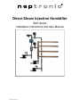
Direct Steam Injection Humidifier SKD Series Installation Instructions and User Manual SKD-121221-ESL.docx Direct Steam Injection Humidifier Installation Instructions and User Manual www.neptronic.com Foreword and Safety Instructions About the Manual These installation and operation instructions have been developed to facilitate the installation of the Direct Steam Injection Humidifier . The strict application of these instructions will ensure the conformity of your installation and operation as per the manufacturer's recommendations. The application of these instructions is one of the conditions for the application of the warranty. The application of these instructions does not ensure, at any time conformity to procedures, regulation or local codes, regarding electric installation and connection to local water supply. This product has been declared to conform to the applicable Canadian and American safety standards and directives and bear the CSA (c) & (us) mark. The Certificate of Conformity, CSA is available, upon request with the manufacturer. 2012©: All rights reserved. This document cannot be reproduced totally or partially by any means whether, electronic, mechanical, photocopy, recording or other, without prior written authorization of Neptronic. Company Overview Neptronic is a private corporation, founded in 1976 that designs, manufactures and distributes products for the Heating, Ventilation and Air Conditioning industry (HVAC). Neptronic products, which include humidifiers, electric heaters as well as electronic damper actuators, actuated valves and control products, are designed, manufactured and assembled by over 200 dedicated employees at its 7,500 m2 (80,000 sq2) state-of-the-art facility located in Montreal, Canada. Neptronic currently holds several national and international patents and with its continued emphasis on research and development, Neptronic ensures innovative technologies to the ever-evolving challenges of our industry. Neptronic has an exclusive distribution network around the globe that provides comprehensive solutions to our customers and meets a worldwide demand that spans 5 continents. Electricity All work concerned with electrical installation MUST only be performed by skilled and qualified technical personnel such as an electrician or a technician with appropriate training). The customer is always responsible for ensuring the suitability of the technical personnel. Please observe the local regulations concerning the provision of electrical installations. Correct Use Neptronic systems and its products are designed only for humidification use. Any other application is not considered appropriate for the intended purpose. The manufacturer cannot be made liable for any damage resulting from incorrect use. Page | ii Direct Steam Injection Humidifier www.neptronic.com Installation Instructions and User Manual List of Figures Illustration 1‐ Multiple Steam Jacketed Distributors .................................................................................... 2 Illustration 2 ‐ Single Steam Jacketed Distributor ......................................................................................... 3 Illustration 3 ‐ Mini Rack ............................................................................................................................... 3 Illustration 4 ‐ Multiple Steam Jacketed Distributors ................................................................................... 4 Illustration 5 ‐ Multiple Steam Jacketed Distributors for Large Capacities .................................................. 5 Illustration 6 ‐ Installation Stages ................................................................................................................. 7 Illustration 7 ‐ Manifold Installation ............................................................................................................. 8 Illustration 8 ‐ End Mounting Bracket and Escutcheon Plate ....................................................................... 8 Illustration 9 ‐ Steam Header with Union ..................................................................................................... 9 Illustration 10 ‐ Mini Rack ............................................................................................................................. 9 Illustration 11 ‐ Control Valve Orientation and Control Valve Angle .......................................................... 10 Illustration 12 ‐ Control Valve Connection to Steam Distributor without Header ..................................... 10 Illustration 13 ‐ Control Valve Connection with Header ............................................................................. 10 Illustration 14 ‐ Separator Proper Installation ............................................................................................ 11 Illustration 15 ‐ Separator Incorrect Installation ........................................................................................ 11 Illustration 16 ‐ Separator Connection to Control Valve ............................................................................ 11 Illustration 17 ‐ Single Steam Distributor Separator Correct Installation ................................................... 12 Illustration 18 ‐ Single Steam Distributor Separator Incorrect Installation ................................................ 12 Illustration 19 ‐ Temperature Sensor Separator Installation ...................................................................... 12 Illustration 20 ‐ Temperature Sensor Jacket Installation ............................................................................ 13 Illustration 21 ‐ Separator Steam Trap Installation ..................................................................................... 13 Illustration 22 ‐ Steam Trap Installation: Distance from Temperature Sensor ........................................... 13 Illustration 23 ‐ Steam Trap Installation ‐ Multiple Steam Distributors ...................................................... 14 Illustration 24 ‐ Control Valve Orientation and Control Valve Angle .......................................................... 14 Illustration 25 ‐ Single Steam Distributor Tube Configuration .................................................................... 15 Illustration 26 ‐ MiniRack and Multiple Steam Distributors Configurations ............................................... 15 Illustration 27 ‐ ESC Wiring Diagram ........................................................................................................... 16 Page | iii Direct Steam Injection Humidifier www.neptronic.com Installation Instructions and User Manual Contents Technical Specifications ................................................................................................................................ 1 Product Description .................................................................................................................................. 1 Configuration ................................................................................................................................................ 3 Single Steam Jacketed Distributor ............................................................................................................ 3 Mini Rack ................................................................................................................................................... 3 Multiple Steam Jacketed Distributors ....................................................................................................... 4 Large Capacities Multiple Steam Jacketed Distributors ............................................................................ 5 Handling and Packing .................................................................................................................................... 6 Installation Overview .................................................................................................................................... 7 Installation Method Statement ................................................................................................................. 7 Stage 1 – Steam Jacketed Distributor Installation ................................................................................ 8 Stage 2 – Steam Header Installation ..................................................................................................... 9 Stage 3 – Control Valve Installation .................................................................................................... 10 Stage 4 – Steam Separator Installation ............................................................................................... 11 Stage 5 – Temperature Sensor Installation ......................................................................................... 12 Stage 6 – Float and Thermostatic Steam Trap Installation ................................................................. 13 Stage 7 – Isolating Valve Installation .................................................................................................. 14 Stage 8 – Y‐Strainer Installation .......................................................................................................... 15 Stage 9 – ESC Device, Electrical Supply, and Control Connections ..................................................... 16 Initial Verification ........................................................................................................................................ 17 Installation .............................................................................................................................................. 17 Electrical .................................................................................................................................................. 17 Drain if needed (MiniRack or Multitubes configurations only) .............................................................. 17 Steam Supply .......................................................................................................................................... 17 Controls ................................................................................................................................................... 17 Start‐Up Procedure ..................................................................................................................................... 18 Start‐up ................................................................................................................................................... 18 Safety Test ............................................................................................................................................... 18 Reset the Set Point and Control Mode ................................................................................................... 18 End .......................................................................................................................................................... 18 General Conditions of Sales and Warranty ................................................................................................. 19 Page | iv Direct Steam Injection Humidifier www.neptronic.com Installation Instructions and User Manual Technical Specifications Product Description The SKD Direct Steam Injection Humidifier maintains the desired humidity set point by using raw steam from a steam boiler as a source of humidity. The SKD's unique engineering ensures the following: There is no undesired energy consumption when there is no humidity demand There will be no water drop ejection on cold start-up The humidifier always functions properly by constantly monitoring the temperature The SKD is controlled by a specially designed Electronic Steam Controller (ESC) that monitors and controls the demand and steam temperature. The controller takes care of the humidifier's controlling, isolating, and steam control valve operations. This is done using temperature sensors’ readings and the special steam control valve opening sequence. The ESC also simplifies the diagnostics process and is a plug and play configuration for direct steam humidification. The SKD Direct Steam Injection Humidifier comes in three configurations - the SKD Single Tube, the SKD Multi Tubes, and the SKD MiniRack. The choice of the configuration is driven by the combination of the humidifier capacity and the required maximum absorption distance. The design can be selected using the Humidisoft software. The Direct Steam Injection Humidifier combines certain unique features, making it one of the most efficient humidifiers. The following are the features of Direct Steam Injection Humidifier : Steam Jacketed Distributor. The stainless steel jacketed manifold allows pressurized steam to circulate around the inner distribution tube, heating the surface and reducing condensation. Separator. The stainless steel construction of the separator is a proven internal configuration, which limits the drop in pressure while providing efficient steam-condensate separation and also supplying hot and dry steam to the control valve. Control and Isolating Valves. Normally, closed globe valve with equal percentage flow characteristics control the flow of steam. Bronze body and brass trim (stainless steel trim optional). The linear electric actuator, is equipped with a heat shield. Electronic Steam Controller (ESC). The Direct Steam Injection Humidifier comes with a microprocessor based ESC, with backlit LCD display that allows programming of the humidity set points, and monitoring parameters such as actual humidity, air flow switch, interlock, and temperature sensors. Strainer. The strainer strains foreign matter from pipelines, and provides protection to the components of the steam humidifier. Temperature Sensor. RTD temperature sensor integrated in a brass thermowell. Float and Thermostatic Steam Trap. Float and thermostat design with universal four port design, all stainless steel internal components. Steam Header. A steam header is supplied on multiple tube configurations for an even distribution of steam into the airstream. Page | 1 Direct Steam Injection Humidifier Installation Instructions and User Manual www.neptronic.com ISOLATING VALVE VENTILATION DUCT STRAINER STEAM JACKETED DISTRIBUTOR HEADER CONTROL VALVE SEPARATOR TEMPERATURE SENSOR FOR SEPARATOR ESCUTCHEON PLATES FLOAT AND THERMOSTATIC STEAM TRAP TEMPERATURE SENSOR FOR JACKET 1 Illustration 1- Multiple Steam Jacketed Distributors Page | 2 Direct Steam Injection Humidifier Installation Instructions and User Manual www.neptronic.com Configuration The following configurations are available for the Direct Steam Injection Humidifier Single Steam Jacketed Distributor Illustration 2 - Single Steam Jacketed Distributor Mini Rack ISOLATING VALVE STRAINER ESCUTCHEON PLATES CONTROL VALVE SEPARATOR TEMPERATURE SENSOR FOR SEPARATOR VENTILATION DUCT STEAM JACKET DISTRIBUTOR AND HEADER (SINGLE PART) TEMPERATURE SENSOR FOR JACKET FLOAT AND THERMOSTATIC STEAM TRAP Illustration 3 - Mini Rack Page | 3 Direct Steam Injection Humidifier Installation Instructions and User Manual www.neptronic.com Multiple Steam Jacketed Distributors ISOLATING VALVE (E) STEAM JACKET DISTRIBUTOR E STRAINER (H) A C I CONTROL VALVE (D) B HEADER (G) B SEPARATOR B 3/4'' NPT C B TEMPERATURE SENSOR FOR SEPARATOR (3/4" NPT) 3/4'' NPT VENTILATION DUCT FLOAT AND THERMOSTATIC STREAM TRAP (3/4" NPT) ESCUTCHEON PLATES TEMPERATURE SENSOR FOR JACKET (3/4" NPT) Illustration 4 - Multiple Steam Jacketed Distributors Page | 4 Direct Steam Injection Humidifier Installation Instructions and User Manual www.neptronic.com Large Capacities Multiple Steam Jacketed Distributors ISOLATING VALVE (E) ESCUTCHEON PLATES STRAINER (H) B C A B CONTROL VALVE (D) B B SEPARATOR TEMPERATURE SENSOR FOR JACKET 1 B B (3/4" NPT) B 3/4" NPT FLOAT AND THERMOSTATIC STEAM TRAP B ( TEMPERATURE SENSOR FOR SEPARATOR B HEADER (G) C 3/4" NPT) (3/4" NPT) 3/4'' NPT VENTILATION DUCT STEAM JACKETED DISTRIBUTOR FLOAT AND THERMOSTATIC STEAM TRAP ( 3/4" NPT) TEMPERATURE SENSOR FOR JACKET 2 (3/4" NPT) Illustration 5 - Multiple Steam Jacketed Distributors for Large Capacities Page | 5 Direct Steam Injection Humidifier Installation Instructions and User Manual www.neptronic.com Handling and Packing Handling and Lifting Lifting or handling MUST be carried out by trained and qualified personnel. Ensure that the lifting operation has been properly planned, assessed for risk and that the equipment has been checked by a competent Health & Safety representative, and effective control measures are in place. It is the customer’s responsibility to ensure that the operators are trained in handling heavy goods and to enforce the relevant lifting regulations. The Direct Steam Injection Humidifier MUST always be handled and lifted with care and should remain in its original packaging for as long as possible prior to installation. The Direct Steam Injection Humidifier package may be carried using a forklift from the underside. Caution should be exercised to ensure balanced load before lifting. Unpacking The Direct Steam Injection Humidifier is shipped inside carton boxes or in a wooden crate. Remove packing and skids prior to commissioning. Page | 6 Direct Steam Injection Humidifier Installation Instructions and User Manual www.neptronic.com Installation Overview All installation work must comply with local regulations. All work related to the installation of the Direct Steam Injection Humidifier MUST only be performed by skilled and qualified technical personnel such as plumbers or technicians with appropriate training. The customer is responsible for ensuring their suitability. For the installation of the Direct Steam Injection Humidifier and associated components, there are no specific tooling requirements. Installation Method Statement Stage 1 – Steam Jacketed Distributor Installation Stage 2 – Steam Header Installation Stage 3 – Control Valve Installation Stage 4 – Steam Separator Installation Stage 5 – Temperature Sensor Installation Stage 6 – Float and Thermostatic Steam Trap Installation Stage 7 – Isolating Valve Installation Stage 8 – Y-Strainer Installation Stage 9 – ESC Device, Electrical Supply, and Control Connections Stage 1 Steam Jacket Distributor and Header (Single Part) Stage 8 Strainer Stage 7 Isolating Valve Stage 2 Steam Header Escutcheon Plates Stage 3 Control Valve Stage 4 Separator Ventilation Duct Stage 5 Temperature Sensor for Separator Stage 9 Stage 6 Float and Thermostatic Steam Trap Stage 5 Temperature Sensor for Jacket Illustration 6 - Installation Stages Page | 7 Direct Steam Injection Humidifier Installation Instructions and User Manual www.neptronic.com Stage 1 – Steam Jacketed Distributor Installation General Considerations Any installation work must be carried out by suitably qualified personnel. Consider the following points before deciding the location for the SKD steam distribution system: Plan a location that is easy to access and permits an easy inspection and servicing of the humidifier. Do not install the humidifier where failure of the appliance could cause damage to the building structure or to other expensive equipment. Verify that the construction of the duct or AHU wall is suitable to support the steam distributors through the duration of the installation life. Positioning the Steam Distributors The steam distributors must be installed to ensure that the visible steam trail is kept to the shortest possible length. Locate the steam distributors far enough from elbow or fan to be in laminar air flow to ensure proper evaporation distance. There must be sufficient straight duct downstream from the steam distributors for absorption of the steam. Union Steam Jacketed Distributors Escutcheon plate End mounting plate Illustration 7 - Manifold Installation For single steam distributor application, position the steam distributor in the middle of the duct. For multiple steam distributors, position the steam distributors so that the distance between them is the same. Use proper size unions to connect the jacket of each steam distributor together. For mini rack models, position the system evenly so that the spacing between the top distributors and the duct/AHU is the same as the bottom distributors and the duct/AHU. Use metal screws to mount the escutcheon plate to the wall of the duct or AHU. Secure the end of the steam distributor with 3/8" (19.5 mm) rods either vertically or horizontally. Illustration 8 - End Mounting Bracket and Escutcheon Plate Page | 8 Direct Steam Injection Humidifier Installation Instructions and User Manual www.neptronic.com Stage 2 – Steam Header Installation Any installation work must be carried out by suitably qualified personnel. Steam Header Installation (with Multiple steam distributors only) Align the outlets of the steam header with the steam inlet of each steam distributors. Use proper size union to connect the steam header to the steam distributors. Refer to Illustration 10 - Mini Rack. The distance between the header and the steam distributor’s inlet port must not exceed 8” (203 mm) and both header and steam distributor ports must be aligned, no elbows can be used to pipe the connection. Mini rack model, the connections between the steam header and the steam jacketed distributors are assembled at the factory. The steam distributors and the header assembly come as separate, single parts. 8" (203 mm) Max Header Steam Dispersion Tube Union Illustration 9 - Steam Header with Union ISOLATING VALVE STRAINER ESCUTCHEON PLATES CONTROL VALVE SEPARATOR TEMPERATURE SENSOR FOR SEPARATOR VENTILATION DUCT STEAM JACKET DISTRIBUTOR AND HEADER (SINGLE PART) TEMPERATURE SENSOR FOR JACKET FLOAT AND THERMOSTATIC STEAM TRAP Illustration 10 - Mini Rack Page | 9 Direct Steam Injection Humidifier Installation Instructions and User Manual www.neptronic.com Stage 3 – Control Valve Installation Any installation work must be carried out by suitably qualified personnel. Control Valve Positioning The body of the valve must be positioned properly to have the steam supply going into the A port and exiting from the AB port. Do not refer to the orientation of the actuator head for positioning, since the head can be reversed. Install the actuated valve between 20 to 30 degrees from the vertical line to reduce the radiant heat to the actuator head. Illustration 11 - Control Valve Orientation and Control Valve Angle Control Valve Installation without Header Use the proper size union to connect the control valve to the steam distributor. The maximum distance between the steam control valve and the dispersion tubes port should be 8” (203 mm). CONTROL VALVE WITH ACTUATOR UNION STEAM DISTRIBUTOR Illustration 12 - Control Valve Connection to Steam Distributor without Header Control Valve Installation with Header Connect the steam control valve to the steam header by using a length of treaded pipe of the proper dimension. The connection between those must not exceed 8” (203 mm) and the steam control valve port must be aligned with the header inlet port. TO STEAM DISTRIBUTOR STEAM HEADER CONTROL VALVE WITH ACTUATOR Illustration 13 - Control Valve Connection with Header Page | 10 Direct Steam Injection Humidifier Installation Instructions and User Manual www.neptronic.com Stage 4 – Steam Separator Installation Any installation work must be carried out by suitably qualified personnel. Steam Separator Positioning The steam separator must be installed so that the steam inlet is always on top. The steam inlet and the condensate outlet must be vertical. S T E A M IN L E T M U ST ALW AYS BE O N TOP STEAM O UTLET CO NDENSATE O UTLET M U ST ALW AYS BE O N THE BOTTOM Illustration 14 - Separator Proper Installation S TE AM O U TLE T CONDENSATE O UTLET S T E A M IN L E T Illustration 15 - Separator Incorrect Installation Steam Separator Installation Position the steam separator so that the steam inlet is always located on the top. The separator steam outlet port must be aligned with the steam control valve inlet port and the distance between the two must not exceed 8” (203 mm). Use the proper size of threaded pipe to connect the steam separator to the control valve. Reducing coupling might be needed to perform the installation between the separator and the steam control valve. Steam header Control valve with actuator Steam inlet Separator Steam outlet Condensate outlet 8" (203 mm) Maximum Illustration 16 - Separator Connection to Control Valve Steam Separator Installation with Single Tube Position the steam separator so that the steam inlet is always located on the top. The steam separator must be connected to the outlet of the jacketed distribution tube and must be positioned below the tube to avoid a build up of condensate in any area in the piping. Page | 11 Direct Steam Injection Humidifier Installation Instructions and User Manual www.neptronic.com D IS T R IB U T O R CO NTR O L VALVE W IT H A C T U A T O R SEPARATOR Illustration 17 - Single Steam Distributor Separator Correct Installation Illustration 18 - Single Steam Distributor Separator Incorrect Installation Stage 5 – Temperature Sensor Installation Any installation work must be carried out by suitably qualified personnel. Temperature Sensor Installation General One temperature sensor shall be installed downstream of the condensate outlet of the steam separator. The SKD system will require at least one and up to five temperature sensors start-up traps depending on the number of steam traps required on the system. SEPARATOR TEMPERATURE SENSOR SEPARATOR CAP Illustration 19 - Temperature Sensor Separator Installation SKD Mini Rack and Multiple steam distributors series will require at least one additional temperature sensor to be installed at the outlet of the steam jacket distributor. Depending on the total steam distributor length and number, the humidifier might require up to 5 temperature sensors on the steam jacket distributors. The system requires 1 temperature sensor for each 50 linear feet (15m) of steam distributors. Page | 12 Direct Steam Injection Humidifier Installation Instructions and User Manual www.neptronic.com Separator Condensate Outlet Temperature Sensor Separator Steam Jacket Distributor Outlet Cap Temperature Sensor Jacket Cap Illustration 20 - Temperature Sensor Jacket Installation Stage 6 – Float and Thermostatic Steam Trap Installation Any installation work must be carried out by suitably qualified personnel. Float and Thermostat Steam Trap Installation Install a float and thermostatic steam trap at each condensate outlet of the SKD system. Do not combine return steam lines into one steam trap. Steam traps can only be combined on the condensate side. The outlet of the float and thermostat steam trap should be connected to the condensate return pipe of the steam boiler system. The distance between the temperature sensor and the steam trap must be between 5” and 7” (100-175 mm). SEPARATOR TEMPERATURE SENSOR SEPARATOR FLOAT AND THERMOSTATIC STEAM TRAP CAP Illustration 21 - Separator Steam Trap Installation 6" (152 mm) Illustration 22 - Steam Trap Installation: Distance from Temperature Sensor Page | 13 Direct Steam Injection Humidifier Installation Instructions and User Manual www.neptronic.com Separator Condensate Outlet Steam Jacket Distributor Outlet Steam Header Condensate Outlet Float and Thermostatic Steamtrap Header Steamtrap Illustration 23 - Steam Trap Installation - Multiple Steam Distributors The header steam trap, refer to Illustration 23 - Steam Trap Installation - Multiple Steam Distributors, must be connected to the drain since there is no pressure upstream of the steam control valve to push the condensate back to the boiler. Therefore, normal draining design applies on the condensate side of the header steam trap slope to evacuate the condensate, and a P-trap (6” or 152 mm) to avoid the steam vapor coming from the drain. All other steam traps can be connected to the condensate return line. Stage 7 – Isolating Valve Installation Any installation work must be carried out by suitably qualified personnel. Isolating Valve Positioning The valve body must be positioned properly to have the steam supply going into the A port and exiting from the AB port. Do not refer to the orientation of the actuator head for positioning, since the head can be reversed. Install the actuated valve between 20 to 30 degrees from the vertical line to reduce the heat transfer to the actuator head. Illustration 24 - Control Valve Orientation and Control Valve Angle Page | 14 Direct Steam Injection Humidifier Installation Instructions and User Manual www.neptronic.com Stage 8 – Y-Strainer Installation Any installation work must be carried out by suitably qualified personnel. Strainer Positioning The strainer must be installed upstream the separator and the isolating valve for any SKD configuration. On the single steam distributor, install the strainer before installing the isolating valve. On Mini Rack and Multiple steam distributors configuration, install the strainer before the steam line splits between the separator and the isolating valve. Isolating Valve Ventilation Duct Strainer Control Valve Steam Jacketed Distributor Separator Escutcheon Plate Temperature Sensor for Separator Float and Thermostatic Steam trap Illustration 25 - Single Steam Distributor Tube Configuration STRAINER (H) ISOLATING VALVE (E) C ESCUTCHEON PLATE A E CONTROL VALVE (D) B F D B SEPARATOR 3/4" NPT F C HEADER TEMPERATURE SENSOR FOR SEPARATOR (3/4" NPT) E 3/4'' NPT VENTILATION DUCT STEAM JACKET DISTRIBUTOR WITH HEADER ( SINGLE PART ) FLOAT AND THERMOSTATIC STEAM TRAP (3/4" NPT) TEMPERATURE SENSOR FOR JACKET 1 (3/4" NPT) FLOAT AND THERMOSTATIC STEAM TRAP (3/4" NPT) Illustration 26 - MiniRack and Multiple Steam Distributors Configurations Page | 15 Direct Steam Injection Humidifier Installation Instructions and User Manual www.neptronic.com Stage 9 – ESC Device, Electrical Supply, and Control Connections Any installation work must be carried out by suitably qualified personnel. Electrical Connection Position the ESC device in a safe, cool, and dry place. Refer to the ESC (Electronic Steam Controller) manual and Illustration 27 - ESC Wiring Diagram to connect all the components to the ESC. Make all the electrical connections required on the ESC. 4 3 2 1 6 5 4 3 TB2 24VAC 24 Vac TS5 2 COM 3 TS6 2- Not used 3- Control Signal 4- 24 Vac 3 NO 1 NC 3 2 Steam Relay TB3 NC KCOM KCOM 2 TS4 1 J5 Isolating Valve Signal NO 1 3 Common Temperature Sensor Jacket 5 TO1 1- Common Steam on Relay Status Alarm Relay 4 COM Temperature Sensor Jacket 4 Common 24VAC 3 TS3 2 J4 TO2 24 Vac COM 2 1 J3 Isolating Valve Actuator 1 TS2 Temperature Sensor Inputs TB12 TB13 COM 3 Temperature Sensor Jacket 3 TS1 2 Common TB11 1 J2 Common or 24 Vac NO COM Alarm Relay TB4 AI4 Temperature Sensor Jacket 2 NO AT060-ESC Supply 3 Common J1 COM TB5 COM Temperature Sensor Separator Temperature Sensor Jacket 1 Analog Inputs TB10 2 S1 AI3 TO3 PD Switch On/Off Humidity Demand On/Off NC TB9 AI2 1 2 Analog Outputs COM 3 High Limit Humidity Sensor AI1 2 Room Humidity Sensor AO2 1 0 – 10 Volts COM 4 External Demand/Setpoint1 AO1 3 Not used -5 24VAC 2 Common Not used -4 1 24 Vac Control Valve Signal DI1 High Limit (digital) 2 2 5 OUT B- DI2 NC Interlock 1 4 OUT A+ TB8 3 COM Common -1 24 Vac -2 Network* IN B- DI3 COM TB1 IN A+ 2 AM060-ESC Control Signal -3 Digital Input TB7 1 Steam Control Valve Actuator DI4 On/Off ESC LEGEND S = Separator J = Jacket NO = Normally Open NC = Normally Close 5 *Network available only on ESCB or ESCD Illustration 27 - ESC Wiring Diagram Page | 16 Direct Steam Injection Humidifier Installation Instructions and User Manual www.neptronic.com Initial Verification Any installation work must be carried out by suitably qualified personnel. Installation Ensure that the humidifier is installed properly according to the installation manual. Check that steam distributors are properly installed into the ventilation duct. Ensure that there is no leakage on the SKD piping. Electrical Confirm that 24Vac is present between tab 1&4 of terminal block TB5 on the ESC Controller. Drain if needed (MiniRack or Multitubes configurations only) If there is a steam trap on the header, confirm that the drain piping is properly connected with a pitch of least ¼’’ (1.5 mm) per 40’’ (1m). There is no header on the single tube configuration and therefore there is no steam trap on the header. Steam Supply If there is a steam trap on the header, confirm that the drain piping is properly connected with a pitch of least ¼’’ (1.5 mm) per 40’’ (1m). There is no header on the single tube configuration and therefore there is no steam trap on the header. Controls Ensure that a high limit duct humidistat is installed, properly connected to the set point is properly adjusted. Verify that the room humidistat or returned air duct humidistat is installed, properly connected to the ESC, and the set point is properly adjusted. Turn on the power at the disconnect switch. Confirm the control set-up of the humidifier. The humidifier is factory set with EXTERNAL control set-up, which means that the humidity demand is controlled by the room or duct humidistat. Ensure that the type of signal (0-10 Vdc, 2-10 Vdc or 4-20 mA) of the humidistat corresponds to the type set in the humidifier control set-up. ESC and the Page | 17 Direct Steam Injection Humidifier Installation Instructions and User Manual www.neptronic.com Start-Up Procedure Start-up Proceed to start-up the humidifier as follows: Make sure that the steam is supplied to the SKD. Switch on the ESC. Make sure that there is no alarm. If the A6 alarm stays on, it means that the steam does not reach the separator or there is a problem with evacuating the condensate from the separator steam trap. Wait for a call for humidity or create it by setting the ESC control mode to ON (set #14), and the External humidity set point to OFF (set #18). Then, adjust the set point to a higher value than the room humidity reading (operation mode B). Set the ESC econo mode to ON. o The isolating valve will open within 30 seconds. If not, check for alarms (no air flow, enable/disable off). If there is no alarm, there is no humidity demand. Make sure there is a demand and redo start up procedure d). o After the isolating valve opens, the temperature of the jacket will increase. Within 30 seconds, the temperature of the jacket should be higher than 212F (100C). The temperature is displayed on the ESC LCD. o Once the temperature is high enough, the control valve will open slowly. o The start-up is completed and the humidifier is now functional. Safety Test Check for steam or condensate leakage while the humidifier is in operation. Reset the Set Point and Control Mode If the humidity set point is controlled by the ESC, reset the set point to the desired relative humidity % (set #20) as suits the room. If the humidity set point is controlled by another device than the ESC, set the internal control signal to OFF. The humidifier is ready for normal operation. End Page | 18 Direct Steam Injection Humidifier www.neptronic.com Installation Instructions and User Manual General Conditions of Sales and Warranty General warranty policy Provided that the terms of payment are observed, the purchaser is offered a warranty of 24 months from the original purchase date of delivery for any Neptronic Humidifier SK300, SKR, SKE, SKS, SKD and SKG Series, provided the equipment has been properly installed and operated in accordance with Neptronic instructions. The warranty covers faulty manufacture, design and/or defective materials and is limited to the equipment and components. The warranty shall cease to be valid in the event of misapplication, incorrect installation, improper maintenance or any other incorrect uses or misuse of the product. For the SK Series, the warranty furthermore ceases to be valid if the user disconnects or removes any electronic or mechanical components prior disconnecting the input power. Neptronic assumes no responsibility for repairs made on equipment, unless performed by Neptronic’s authorized personnel. All defective product or component under warranty must have a valid Return Material Authorization (RMA) number issued prior to be processed. To request an RMA number, purchaser must provide the model number and serial number/date code of humidifier and certain components such as sensor and PC board etc. Neptronic agrees under the warranty to repair or replace (at the discretion of Neptronic) such standard products or components, which on examination by Neptronic are found to be defective. Product or component replaced or repaired under warranty will be sent back to the purchaser, standard ground freight paid by Neptronic. Expenses in connection with travelling time, dismantling and mounting shall not be paid by Neptronic. Guarantee for products or components sold but not manufactured by Neptronic, is only given to the same extent as given to Neptronic, however, not exceeding the normal Neptronic warranty. Parts used for repairs are warranted for the balance of the term of the warranty on the original humidifier or 90 days, whichever is longer. Any repairs made at the Neptronic facilities after the original warranty period are warranted for 1 month from the date of repair. Special agreement on components under warranty For certain defected components under warranty, based on valid reasons, the purchaser has two options: 1) Send back immediately the defective component(s) for inspection and the purchaser is responsible for freight to Neptronic. The full purchase price will be credited once the defective component(s) is received and the manufacturing defect is found upon inspection by Neptronic. OR 2) Replacements will be sent without requiring returning of the defective component(s), standard ground freight paid by Neptronic at zero value invoice. Although the purchaser must hold defective component(s) for a period of 12 months whereas Neptronic reserves the right to claim the defective component(s) back for inspection at any time. If the claim is found to be out of warranty coverage upon inspection by Neptronic, the replacement parts sent free of charges will be then charged to the purchaser. Page | 19 400 Lebeau blvd, Montreal, Qc, H4N 1R6, Canada www.neptronic.com Toll free in North America: 1-800-361-2308 Tel.: (514) 333-1433 Fax: (514) 333-3163 Customer service fax: (514) 333-1091 Monday to Friday: 8:00am to 5:00pm (Eastern time)