1
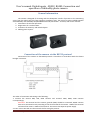
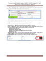
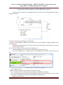
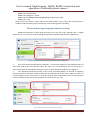
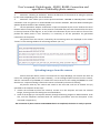
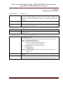
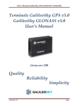
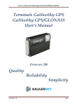
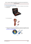
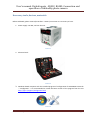
User’s manual. Digital inputs - RS232, RS485. Connection and operation of GalileoSky photo camera Necessary tools, devices, materials Before GalileoSky photo camera (hereinafter– camera) connection it is necessary to have: 1. Power supply: 10÷30V, not less than 1А. Picture 1 2. Electrical tools. Picture 2 3. Windows-based computer with the installed program of configuration of GALILEOSKY terminals – "Configurator". It is recommended to install the latest version of the program from the site http://7gis.ru/support/konfigurator.html Picture 3 SPA “GalileoSky” LLC Page 1 User’s manual. Digital inputs - RS232, RS485. Connection and operation of GalileoSky photo camera General information The camera is designed for shooting and the subsequent transfer of pictures to the monitoring server from the vehicle and (or) from stationary installation sites. The camera is to be installed together with GalileoSky and GalileoSky GPS/GLONASS terminals (hereinafter - terminal) and can be used for: 1. Automation of technical processes. 2. Registration of a road situation. 3. Protection of stationary and mobile objects. 4. Making photo reports. Picture 4. Appearance of the camera Connection of the camera via the RS232 protocol Connection of the camera via the RS232 protocol is carried out in accordance with the scheme brought in Picture 4. Picture 4. RS232 protocol connection scheme The order of connection and setting is the following: 1. Connect the camera RXD, TXD, GND contacts and terminal TXD0, RXD0, GND contacts correspondingly. Attention! The terminal and the camera grounds (GND) should be connected; RS232 contacts have to be connected strictly according to the scheme: RXD of the camera - TXD0 of the terminal and ТXD of the camera - RXD0 of the terminal. The camera has separate power supply. 2. Insert a micro SD card into the terminal slot for saving the pictures. SPA “GalileoSky” LLC Page 2 User’s manual. Digital inputs - RS232, RS485. Connection and operation of GalileoSky photo camera 3. Configure RS232[0] input of the terminal for operation with the camera (Pic. 5): Go to the “Settings” tab -> “Digital inputs” of the Configurator and select “photo camera Galileo” or give the RS2320 4 command in the “Commands” tab; Picture 5. RS232 input setting in the Configurator Press “Apply” button; Go to the “Device” tab of the Configurator and reset the terminal by pressing “Reset device” button or give the Reset command in the “Commands” tab. 4. Make sure that the terminal operates with the camera correctly: Go to “Commands” tab of the Configurator and give the makephoto command; Go to “Troubleshooting” tab and tick the field “RS232[0]”. When the terminal receives a picture from the camera, the following message will be displayed in troubleshooting: RS232[0].cam. Snapshot start. RS232[0].cam. ImageSize = 28160. RS232[0].cam. Pic/RS0/20131025/043925.jpg created successfully. RS232[0].cam. rx pic. Check LED of the camera – green LED on the camera blinks rarely (1 time per second) when in standby mode and quickly (up to 10 times per second) during picture recording. 5. Visually estimate the quality of a picture in the “Device” tab in the Configurator (Pic. 6), Picture 6. Picture check in the Configurator SPA “GalileoSky” LLC Page 3 User’s manual. Digital inputs - RS232, RS485. Connection and operation of GalileoSky photo camera Connection of the camera via the RS485 protocol Connection of the camera via the RS485 protocol is carried out in accordance with the scheme brought in Picture 7. Picture 7. RS485 protocol connection scheme The order of connection and setting is the following: 1. Connect camera RS485_A, RS485_B, GND contacts and terminal RS485_A, RS485_B, GND contacts correspondingly. Attention! Grounds (GND) of the terminal and the camera should be connected! The camera has separate power supply. 2. Insert a micro SD card into the terminal for saving pictures. Configure RS485 input of the terminal to operate with the camera (Pic. 8): Go to the “Settings” tab -> “Digital inputs” of the Configurator and select “photo camera and FLS”; Picture 8. RS485 input setting in the Configurator Press “Apply” button; 3. Make sure that the terminal operates with the camera correctly: Go to “Commands” tab of the Configurator and give the makephoto command; Go to “Troubleshooting” tab and tick the field “RS485”. When the terminal receives a picture from the camera, the following message will be displayed in troubleshooting: RS485.cam. Retrans ok. SPA “GalileoSky” LLC Page 4 User’s manual. Digital inputs - RS232, RS485. Connection and operation of GalileoSky photo camera RS485.cam. Snapshot start. RS485.cam. ImageSize = 22176. RS485.cam. Pic/RS4850/20131025/050953.jpg created successfully. RS485.cam. rx pic. Check LED of the camera – green LED on the camera blinks rarely (1 time per second) when in standby mode and quickly (up to 10 times per second) during picture recording. Photo camera operating parameters setting Additional parameters of work with the camera you may set in the “Settings” tab -> “Digital inputs” (Pic. 9), or you may use the PhotoCfg command (see command description in Appendix 1). Picture 9. Setting of camera operating parameters in the Configurator 1. First of all set the Shooting Period parameter – an interval of frequency with which pictures are taken and saved to the micro SD card. When the value “0” is set shooting by event is carried out, in other words when the makephoto command is given or when signaling conditions are triggered. 2. The “Shooting period with sending to the server” parameter defines an interval of frequency with which pictures are taken, saved to the micro SD card and sent to the server. When the value is 0 only shooting by event is carried out. In order the pictures were transmitted to the monitoring server correctly make sure that the server parameters are correctly set. (Pic. 10). Picture 10. Example of server parameters settings SPA “GalileoSky” LLC Page 5 User’s manual. Digital inputs - RS232, RS485. Connection and operation of GalileoSky photo camera 3. Parameter “Shooting in Geofences” defines the behavior of the terminal on taking the pictures by the camera depending on the use of Geofences. 4. Parameter “Size” allows you to set the picture resolution: 640х480 or 320х240 points. If GPRS connection is not very good, it is recommended to set a lower resolution, which will allow increasing the speed of pictures transfer to the monitoring server. 5. The last parameter “Require confirmation of picture reception by the server” defines the server behavior when receiving the picture. As the pictures are divided into parts and transmitted to the server in this way because of their big size, in case of lack of confirmation by the server and loss of one of the packets the whole picture is lost. Therefore, it is necessary to set this parameter for guaranteed transmission of the picture. The pictures from the camera, received by the monitoring server are displayed in the column “Picture” of the message window of monitoring software. (Pic. 11). Picture 11. Example of picture displaying in monitoring software Uploading images from the camera Pictures from the camera, which is connected to zero input RS232[0], are saved to the micro SD card to the catalog Pic\RS0, to the input RS232[1] – to the catalog Pic\RS1. Pictures from the camera, which is connected to input RS485, are saved to the micro SD card to the catalog Pic\RS4850. For each date there is a separate catalog created. Files names are formed by the time of shooting. All pictures taken by the camera and saved to the micro SD card can be viewed and (or) uploaded to the computer in two ways: 1. remove the microSD card from the terminal, connect it to the computer and save the selected images, focusing on the file catalog structure listed above; 2. some of the images you can request remotely through monitoring program or SMS command. To do this, send the Getphoto command with the necessary parameters (see the description of the command in Appendix 1). The connection of photo camera to GALILEOSKY device is completed, the device is ready to operate. SPA “GalileoSky” LLC Page 6 User’s manual. Digital inputs - RS232, RS485. Connection and operation of GalileoSky photo camera Appendix 1 Command to control the camera Command format Parameters Explanation Example GetPhoto d,t,n d – photo date, format DDMMYY, where DD – day, MM – month, YY – year;t – photo time, format HHMMSS, where HH – hours, MM – minutes, SS – seconds;n – RS232 port number to which the camera taking photos is connected.. Request to transmit the nearest to the given time and data photo to the server. Request: GetPhoto 050511,052030,0 Reply: Send of photo is scheduled Command format MakePhoto Explanation Example Take a photo and send it to the server. Request: MakePhoto Reply: Photo ok Command format Parameters PhotoCfg t1,t2,mode,res,confirm t1 - periodic shooting interval, [sec]. Photos are saved only to the SD-card, 0 – shooting only by event; t2 - shooting interval [sec]. Photos are saved to the SD-card and sent to the server, at 0– shooting only by event mode - periodical shooting in geofences: 0 - photos are taken regardless of geofences; 1 - photos are taken only inside geofences; 2 - photos are taken only outside geofences. res - picture resolution: 0 - 640х480 points; 1 - 320х240 points. confirm - waiting for a confirmation of a picture reception from the server: 0 – do not wait; 1 - wait. Settings of a periodical camera shooting, picture format and an image transfer protocol. Request: PhotoCfg 5,150,0,0,0 Reply: PHOTOCFG:WrPeriod=5,SendPeriod=150,Type=0,Size=0,Confirm=0; Explanation Example SPA “GalileoSky” LLC Page 7