1
User’s Manual GalileoSky GPS/GLONASS (0200)
Terminals GalileoSky GPS
GalileoSky GPS/GLONASS
User’s Manual
firmware 200
Quality
GalileoSky Ltd
Reliability
Simplicity
Page 1
User’s Manual GalileoSky GPS/GLONASS (0200)
Contents
Introduction ........................................................................................................................................................ 5
Package .............................................................................................................................................................. 7
Technical specifications ...................................................................................................................................... 8
Physical specifications ........................................................................................................................................ 9
Safe maintenance rules ....................................................................................................................................10
Contacts description .........................................................................................................................................10
Connecting ........................................................................................................................................................11
Connecting GPS or GLONASS aerial..............................................................................................................11
Connecting GSM aerial .................................................................................................................................11
Inserting SIM-card ........................................................................................................................................12
Connecting power supply to the device .......................................................................................................12
LED indicators ...............................................................................................................................................12
Terminal units performance .............................................................................................................................13
Discrete analogue inputs (DAI) .....................................................................................................................13
Pulse count ...............................................................................................................................................14
Mean value and discrete event generation .............................................................................................14
Frequency count .......................................................................................................................................14
Frequency count from two synchronously connected sensors ...............................................................14
Determination of shock and incline .............................................................................................................15
Economical driving "EcoDrive" and determination of the driving style .......................................................16
Data archiving to the external SD card.........................................................................................................16
Autoinformer function .................................................................................................................................17
Signaling function .........................................................................................................................................19
Monitoring data transmission ......................................................................................................................20
Internal Archive Structure ............................................................................................................................20
GPRS traffic costs optimization ....................................................................................................................21
Operation in international roaming .............................................................................................................21
Stels mode and packet transmission ............................................................................................................22
Geographical areas .......................................................................................................................................22
Power saving ................................................................................................................................................23
Remote configuration ..................................................................................................................................23
Connecting external peripherals.......................................................................................................................24
CAN-interface ...............................................................................................................................................24
J1939_SCANER mode ...............................................................................................................................24
FMS mode.................................................................................................................................................25
J1939_USER_29bit mode .........................................................................................................................25
J1979_SCANER mode ...............................................................................................................................26
J1979_USER_29bit mode .........................................................................................................................26
Device CAN-bus connection options ........................................................................................................27
Connecting RS232 protocol digital fuel gauges ............................................................................................28
GalileoSky Ltd
Page 2
User’s Manual GalileoSky GPS/GLONASS (0200)
Connecting GalileoCam photocamera to the device ...................................................................................29
Connecting RS232-RS485 adapter ................................................................................................................30
Connecting 1Wire sensors............................................................................................................................31
Connecting iButton (DS1990, DS1982) identification key ........................................................................31
Connecting DS18S20 (DS1820, DS18B20) thermometers and temperature and humidity sensors
(DS1923) ...................................................................................................................................................31
Connecting Autoinformer speaker ...............................................................................................................33
Transistor outputs (0/1) ...............................................................................................................................33
Connecting audio equipment and push-to-talk Tg V1.x...............................................................................34
Connecting GLONASS accessory ...................................................................................................................35
Connecting REP-500 electricity meter..........................................................................................................35
Connecting passenger flow registration sensors Ш2 ...................................................................................36
Connecting Garmin navigators supporting FMI protocol .............................................................................37
Connecting course detector Trimble ............................................................................................................37
Connecting CAN-LOG....................................................................................................................................38
Connecting CUB5B indicator ........................................................................................................................38
Connecting Weight Indicator CI5010A .........................................................................................................39
Configurator .....................................................................................................................................................40
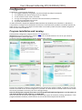
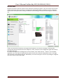
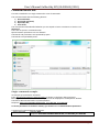
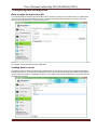
Program installation and running.................................................................................................................40
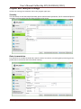
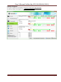
Device tab .....................................................................................................................................................41
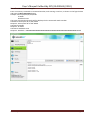
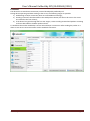
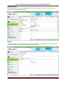
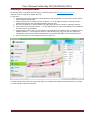
Troubleshooting tab .....................................................................................................................................43
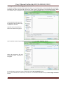
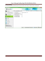
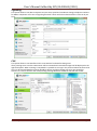
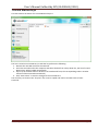
Command mode tab.....................................................................................................................................46
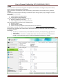
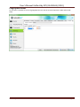
Graphic user interface settings ....................................................................................................................49
Security .....................................................................................................................................................49
Data transmission .....................................................................................................................................49
Protocol ....................................................................................................................................................50
Power saving ............................................................................................................................................51
Track .........................................................................................................................................................52
Inputs/Outputs .........................................................................................................................................53
Digital inputs.............................................................................................................................................54
Sound........................................................................................................................................................54
Signaling ...................................................................................................................................................55
CAN ...........................................................................................................................................................55
Geographical areas ...................................................................................................................................56
Transferring and sending data .....................................................................................................................57
Data transfer from device to file ..............................................................................................................57
Sending data to server .............................................................................................................................57
Routes for autoinformator ...........................................................................................................................58
Trusted iButton keys ....................................................................................................................................59
Commands list ..................................................................................................................................................60
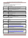
SMS management enabling settings ............................................................................................................60
Data transmission settings ...........................................................................................................................60
GalileoSky Ltd
Page 3
User’s Manual GalileoSky GPS/GLONASS (0200)
Server exchange protocol settings ...............................................................................................................62
Track parameters setting .............................................................................................................................64
Geographical areas settings .........................................................................................................................66
Information commands ................................................................................................................................67
Service commands........................................................................................................................................69
Voice communication settings .....................................................................................................................71
Discrete-analog input setting .......................................................................................................................72
Transistor output setting ..............................................................................................................................72
Autoinformer setting ....................................................................................................................................73
Digital inputs settings ...................................................................................................................................73
Signaling mode setting .................................................................................................................................76
CAN settings .................................................................................................................................................79
Packet transmission, energy saving, Stels modes setting ............................................................................79
Photocamera operation setting ...................................................................................................................80
Bootloader ........................................................................................................................................................81
USB channel download.................................................................................................................................81
GPRS channel download...............................................................................................................................81
Using analog inputs to enter bootloader mode ...........................................................................................81
LED operation during flashing. .....................................................................................................................81
Server communication protocols ......................................................................................................................82
FAQ ...............................................................................................................................................................91
Additional information .....................................................................................................................................92
GalileoSky Ltd
Page 4
User’s Manual GalileoSky GPS/GLONASS (0200)
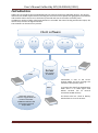
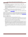
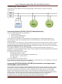
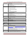
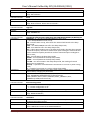
Introduction
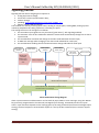
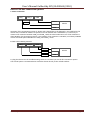
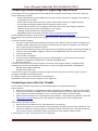
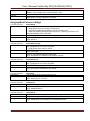
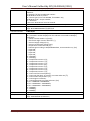
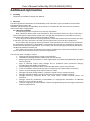
Galileo sky Ltd. produces GPS and GLONASS real time vehicles monitoring GalileoSky devices. The devices
determine the mobile object location recording the time and route as points with geographical coordinates
and send the data to the server to be further processed and sent to the traffic controller panel.
In addition a number of other vehicle parameters are recorded: the state of analog and discrete inputs, the
device state, the state of digital interfaces.
The terminals can be used in any vehicle.
Client software
Server
GPRS
GPRS
with a static
IP-address
Information is sent to the server
through GPRS and then through the
Internet to the operator panel.
GPRS
GalileoSky terminal
receives a signal about its
location from GPS,
GLONASS satellites and
processes input and
output data.
GalileoSky Ltd
To prevent the data from disappearing
when there is no GSM signal each
Galileo terminal has an internal
nonvolatile FLASH memory.
The device also has a built in battery
which allows it to run for 8 hours.
Page 5
User’s Manual GalileoSky GPS/GLONASS (0200)
The device provides the following opportunities:
Vehicles monitoring in real time;
A detailed turn by turn track (without any extra points in a straight track);
Voice communication with the traffic dispatcher;
GSM enabled remote software update;
Continuous troubleshooting of the device through the USB port;
Car alarm and a remote engine start;
Securing facilities against intrusion;
Automatic stops announcement;
Adjusting the device through SMS, GPRS. USB;
And others (see Terminal units performance and Connecting external peripherals).
The information sent by the terminal includes:
The exact Greenwich time and date;
Vehicle coordinates: latitude, longitude, height;
Vehicles speed and direction;
Vehicle acceleration;
Inside temperature;
Input (buttons) and analog sensors state;
External digital sensors state (fuel, temperature sensors etc.);
Discrete outputs state;
And others (see details of transmitted data in GalileoSky protocol)
In addition the company provides warranty service and technical support on its site and forum.
Before starting the work study the instruction carefully.
GalileoSky Ltd
Page 6
User’s Manual GalileoSky GPS/GLONASS (0200)
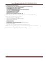
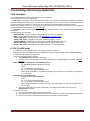
Package
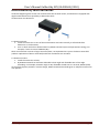
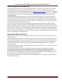
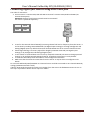
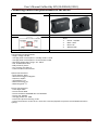
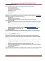
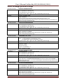
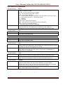
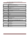
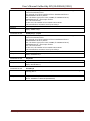
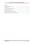
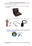
The standard package includes the Galileo terminal (hereinafter referred to as the terminal) and a pin
connector. Everything extra should be bought separately.
The device appearance:
1.
2.
3.
4.
5.
6.
1 2
4
5
Разъем для антенны GSM
Разъем для антенны GPS/ГЛОНАСС
SIM holder
USB slot
SD slot
Основной разъем
6
3
The terminal has 4LED indicators which show its current status: red (external power supply), yellow
(microcontroller), green (GPS or GLONASS receiver), blue (GPRS modem). See LED indicators.
You will also need:
1. USB cable
2. GLONASS aerial
3. GSM aerial
4. Power supply unit
GalileoSky Ltd
1
1
1
9-39V (15 W) 1
Page 7
User’s Manual GalileoSky GPS/GLONASS (0200)
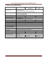
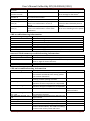
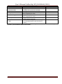
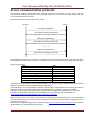
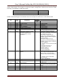
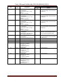
Technical specifications
Parameter
Discrete analog and pulse
frequency inputs
Transistor outputs (output
0/1)
Cell type
Average consumed power
ADC capacity in bits
FLASH memory capacity
1-Wire
CANBUS
RS232
USB 2.0
MicroSD
Speakerphone
Speaker (Autoinformer)
The number of geographical
areas for voice prompts
Speaker output
The size of a data packet sent
by the device
Accelerometer
Type of GLONASS receiver
Type of GLONASS receiver
Coordinates determination
accuracy, 95% of time
GSM modem
Moisture protection
GalileoSky Ltd
Galileo GPS
Galileo GLONASS
v2.2.0-v2.2.5
Galileo GLONASS
v2.2.8
4 pcs;
voltage range 0-33V;
Maximum frequency for pulse frequency inputs 2kHz;
Input resistance of every input is 14 kOhm to the ground;
4 pcs;
maximum voltage supply 30V;
maximum current supply 80mA
Li-Ion battery 600mA
1,2W
1.6W
1.5W
10;
up to 58000 points;
up to 5000000 points when using microSD card
Yes
Yes
Yes
J1939,FMS, J1979, OBD ΙΙ, 29-bit and 11-bit identifiers
1
1
2
Terminal troubleshooting, adjusting, reflashing
Maximum capacity of supported card is 32 gigabytes
yes
built in
Limited by the microSD card capacity
analogue (linear output) 250mW
GalileoSky protocol: variable size, tag format
built in
MTK, 55 channels
GeoS-1M
MGGS2217
GSM 850/900/1800/1900,
GPRS class 10
GSM 900/1800,
GPRS class 10
within 5 m
GSM 900/1800,
GPRS class 10
No
Page 8
User’s Manual GalileoSky GPS/GLONASS (0200)
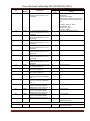
Physical specifications
Operating temperature range
Extended temperature range
Storage temperature
Relative humidity
Performance (height above the sea level)
Storage
Continuous work form battery
External power supply
Size
Weight
Body material
-30...+60 °C
-40...+85 °C
-40...+85 °C
0...90% (0...35 °C); 0...70% (35...55 °C)
0-2000 m
0-10000 m
depends on the settings, 8hrs on average
10-30V; is protected against voltage jumps in the vehicle
power supply
103,0 mm x 65,0 mm x 28,0 mm
within 300g
Metal
Warranty
2 year since the purchase date;
Average service
10 years
Internal Li-Ion battery life
500 charge/discharge cycles, two years maximum
GalileoSky Ltd
Page 9
User’s Manual GalileoSky GPS/GLONASS (0200)
Safe maintenance rules
Before using the terminal study the instructions of GSM/GPRS devices safe maintenance.
Make sure the polarity is correct when connecting to the power supply.
The device should be connected straight to the vehicle battery, not to the vehicle power supply.
Caution! To avoid failure:
Make sure the contacts are connected correctly!
Unused contacts must be well insulated!
The ground is connected to the device body. In order not to damage the terminal or the vehicle’s
electronics it is necessary to separate the device body and the vehicle.
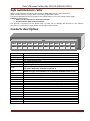
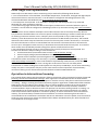
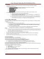
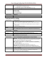
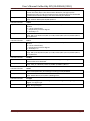
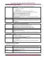
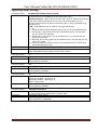
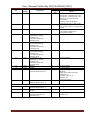
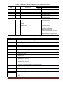
Contacts description
Mic0
Spkr0 Out2
Mic1
Spkr1 AGND Out1 CAN_L CAN_H GND
Contact
+10/+30V
GND
IN0
IN1
IN2
IN3
RXD0
TXD0
RXD1
TXD1
1-Wire
GND
Vol0
CAN_H
Vol1
CAN_L
Out0
Out1
Out2
AGND
Spkr0
Spkr1
Mic0
Mic1
GalileoSky Ltd
Out0
Vol1
Vol0
1-Wire RXD1 RXD0
TXD1 TXD0
IN2
IN0
+9/39v
IN3
IN1
GND
Description
Positive supply voltage
Negative supply voltage
Zero analog discrete input
First analog discrete input
Second analog discrete input
Third analog discrete input
Zero channel RS232 RXD signal
(not used in GalileoSky GLONASS v2.2.0-v2.2.5)
Zero channel RS232 TXD signal
(NMEA-messages from GLONASS unit in GalileoSky GLONASS v2.2.0-v2.2.5)
First channel RS232 RXD signal
First channel RS232 TXD signal
1-Wire interface
Ground to connect interfaces which need the ground contact
Zero contact to connect an external speaker for signalling or autoinformer
CAN interface CAN_H contact
First contact to connect an external speaker for signalling or autoinformer
CAN interface CAN_L contact
Zero transistor output (output 0/1)
First transistor output (output0/1)
Second transistor output (output0/1)
Contact for external headset’s shield connection (microphone, speaker)
External headset’s speaker’s zero contact
External headset’s speaker’s first contact
External headset’s microphone’s zero contact
External headset’s microphone’s first contact
Page 10
User’s Manual GalileoSky GPS/GLONASS (0200)
Connecting
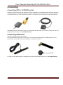
Connecting GPS or GLONASS aerial
Carefully screw the aerial to the terminal, the upper side above. For GalileoSky GPS terminals should be
used GPS aerial, for GalileoSky GLONASS terminals – GLONASS aerial. To have a better view of the sky it is
recommended that the aerial should be mounted on the vehicle roof, windscreen or under the dashboard.
If GLONASS aerial is mounted correctly, your coordinates will be found in 1.5 minutes. To be sure see that
the green LED indicator is on. (See’ LED indicators’).
Connecting GSM aerial
Carefully screw the aerial to the terminal.
The aerial should be mounted in such a way so as to prevent the GSM signal from fading because of the
vehicle body, for example, under the dashboard or outside the vehicle.
To make sure the GPRS modem is sending data see that the blue LED indicator is on. (see’ LED indicators’).
GalileoSky Ltd
Page 11
User’s Manual GalileoSky GPS/GLONASS (0200)
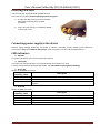
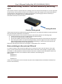
Inserting SIM-card
Use the card with activated GPRS and SMS services.
Insert the card carefully without applying unnecessary force.
1) To eject the SIM holder press the indicated
place with something sharp (needle,
toothpick);
2) Insert the card so that it is completely hidden
in the holder cover.
2 1
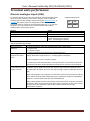
Connecting power supply to the device
Positive supply voltage should be connected to contact +10/+30V, supply voltage minus should be
connected to GND. (See Contacts description). If the connection is correct, the red LED will be on.
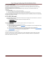
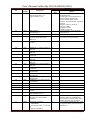
LED indicators
Red LED
Is on when the power unit is connected to the terminal.
Yellow LED
Is on when the microcontroller is running (blinks with the frequency of 1 Hz).
It is also used to indicate the bootloader mode. (see LED indicators during device flashing)
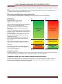
Green LED
Shows the GLONASS unit status.
Blinking
frequency, times
3
2
1
Description
GLONASS unit is not found and is at the initialization state
GLONASS unit is found but coordinates are absent
GLONASS unit works properly, coordinates found and updated once a
second
Blue LED
Shows the GSM unit status.
Blinking
frequency, times
4
3
2
1
GalileoSky Ltd
Description
Stels mode (GSM unit is off and is set to be on according to schedule)
GSM unit is not found or is at the initialization stage
GSM unit is found but there is no server connection
GSM unit works properly, server is connected
Page 12
User’s Manual GalileoSky GPS/GLONASS (0200)
Terminal units performance
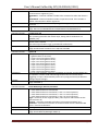
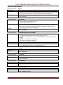
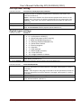
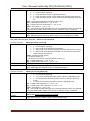
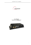
Discrete analogue inputs (DAI)
To attach external sensors the terminal has 4 discrete analogue inputs
which are pulse-frequency. Each input’s function is set in terminal
settings (see Discrete analogue inputs setting and Inputs/outputs). In
Contacts description inputs are designated as IN0, IN1, IN2, IN3.
Each input saves its values to the nonvolatile memory, i.e. in case the
channel is set to be a pulse one, the pulse number value will be
restored after resetting the device.
Feature
Maximum measured voltage
Analog inputs resolution
Maximum transmitted signal frequency
4 digital-analog inputs
IN2
IN0
IN3
IN1
Value
33 V
33 mV
2 kHz (synchronous measuring at 2 inputs)
1.5 kHz (measuring at 3 inputs)
1 kHz (measuring at 6 inputs)
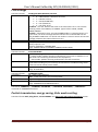
DAI has the following settings:
Parameter
Explanation
Filter type (input
0 – mean arithmetic value (also discrete input state is generated);
function)
1 – pulse count;
2 – frequency input;
3 – pulse count from two synchronous connected sensors.
Filter length to
The greater this parameter, the more slowly the device responds to the input signal
calculate the mean
change. With filter length equal to 1 - averaging does not happen.
value
Set this parameter to 1 for frequency inputs.
Ranges for response
/ nonresponse areas
(logical 1 and 0)
It is necessary to set this parameter to 1 for pulse inputs. If the terminal counts an
extra pulses, the filter length should be increased by one and accuracy estimated.
To process discrete signals, discrete signal response/nonresponse range should be
set where signals equal to one and zero. Discrete input statuses should be seen in
the field Status Of Inputs, but not in the Input voltage. (Table 2. GalileoSky protocol
tags).
While counting pulses or frequency it is necessary to put the value equal to half the
pulse value into all the fields of the given group. (example: the pulses' amplitude is
5000 mV, so all the fields must take the value 2500 mV)
While counting pulses from 2 synchronous connected sensors, response zone limits
must be the same and equal to half of pulse value at response of one of the sensors.
Non-response zone limits are equal to half of pulse value at two sensors
simultaneous response.
GalileoSky Ltd
Page 13
User’s Manual GalileoSky GPS/GLONASS (0200)
Pulse count
In case of a renewable counter the maximum pulse number can be 65535, after that the number is reset to
zero.
If there is pulse at input, correspondent bit is set in Status Of Inputs field, and point is recorded. If there is
no another pulse for 30 seconds, bit returns to 0.
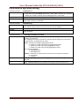
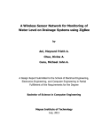
Mean value and discrete event generation
Let us consider the example with the following zero input setting (see the left-hand figure):
Filter type is 0;
Filter length is 5;
Logical one zone range is 8-33V;
Logical zero zone range is 0-3V.
V
V
33
33
The mean value is calculated continuously and is
put into the corresponding field IN0.
At the same time it is continuously checked
whether the calculated value belongs to the
given range.
If it is in the range 8-33V, the corresponding bit
will find itself the Status Of Inputs field and point
will be recorded.
At value coming into the indifference zone (3V8V), the former bit value will be saved to the
Status Of Inputs field.
If the value is in the logical zero zone (0V-3V),
the corresponding bit in the Status Of Inputs
8
field is reset.
Thus we can see that the given bit changes its
state only in the logical one/logical zero zone.
Example2.
In contrast to example 1 (see the right-hand
figure) the logical one zone and the logical zero
zone have changed places.
Frequency count
3
0
Operating zone,
logical 1
Nonoperation
zone, logical 0
8
Indifference zone
Nonoperation
zone, logical 0
Indifference zone
3
Operating zone,
logical 1
0
To measure frequency in some sensors it is necessary to connect the sensor frequency output to the sensor
positive power supply via a 1kOhm resistor. Otherwise frequency count is impossible.
Frequency count from two synchronously connected sensors
Terminal allows connection of 2 pulse sensors on one input, in this case pulse fronts number is count, i.e.
for each sensor response counter value increases for 2. Connection circuit details are given in section
Connection of passengers flow registration gauge Ш2.
GalileoSky Ltd
Page 14
User’s Manual GalileoSky GPS/GLONASS (0200)
Determination of shock and incline
All devices beginning from version 1.9 can determine the terminal incline, and the devices equipped with
digital accelerometer have possibility to determine shock.
Accelerometer axis directions:
To determine shock:
1. Install the terminal so as one of the accelerometer axis looks vertically, it will exclude false
detections on road unevens;
2. Turn on shock and incline determination by SHOCK command (see Track parameters setting). For
example, if Z axis is vertical: SHOCK 3,90,5.
Shock is acceleration increase of 4g in horizontal plane, correspondent bit is put in the device state field
(Table 3. Explanation of device state field) and shock coordinates are recorded.
To determine incline:
1. Install the terminal in vehicle;
2. By SHOCK command set maximum allowable incline angle and allowable time of this angle
exceeding. For example, maximum angle is 20º, allowable exceed time is 5 seconds; SHOCK 3,20,5.
At the terminal peace position in vehicle change, SHOCK command should be given to adopt the terminal to
new position.
GalileoSky Ltd
Page 15
User’s Manual GalileoSky GPS/GLONASS (0200)
Economical driving "EcoDrive" and determination of the driving
style
The terminal can detect rapid acceleration, braking, harsh turns and shock on bumps. For correct operation
of this function, the terminal must detect its orientation in space with respect to the vehicle (the vehicle´s
running direction and the direction in respect to the ground). The driving style data is stored only if
dynamic archive is enabled (command FLASHARCHIVE 1).
The default orientation of the terminal:
Driving direction
Direction to the ground
If the terminal cannot be installed as illustrated by the picture, user-defined installation may be performed
with the subsequent calibration of orientation.
To determine the position of the terminal in respect to the vehicle, perform the following steps:
1. Install the terminal to ensure its rigid link with the vehicle’s body;
2. Ensure the horizontal position of the vehicle;
3. Execute the SHOCK 0 command, which will determine the direction of the terminal to the ground;
4. Start driving the vehicle at a speed exceeding 20 km/h; choose straight-line sections of the road
while driving and keep performing acceleration and braking; in a few minutes the terminal will
perform determination of the running direction.
Data on the driving style can be sent out using the "mainpackbit 174,1" command.
Data archiving to the external SD card
To create a backup on the external microSD card it is necessary to insert it into the device. If the need
arises, it can be ejected from the terminal and the data can be read in a file manager or explorer with a
card reader. It is also possible to send the archive to the server. CSV-files can be opened both with a text
editor and Microsoft Excel. The saved data will be ordered in the following way:
MSD:\[track]
20100201.csv
20100202.csv
…
20100331.csv
If there isn’t enough space on the microSD card, (less than 12 MB) the device will delete the oldest files
from the Track directory.
GalileoSky Ltd
Page 16
User’s Manual GalileoSky GPS/GLONASS (0200)
Autoinformer function
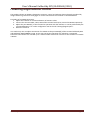
Autoinformer function may be used for automatic (without participation of the driver) public transport
stops announcement with the use of satellite navigation system.
The main difference from analogous systems is taking into account vehicle movement direction, thereby
excluding false operation at other stops located in the same geographic area.
To use autoinformer:
1. Attach the speaker to the terminal (see Connecting auntoinformes speaker).
2. Set the microSD card:
a. Place sound files in format: wav, 16 kHz, mono, 16 bit to the card root folder. The file name
must not exceed 20 symbols, including the extension, for example, PARKOVIJ.wav. The
record length is recommended within 4 minutes (in case of exceeding, at the following file
reproduction crackle may appear);
b. Create folders with routes names in the card root folder. The smallest number of routes is
1.
c. It is necessary to place the BusLine.txt file to the route folders, where response areas and
areas linkage to the sound files are stored.
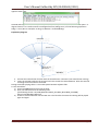
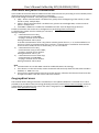
The format of each zone is the following:
Latitude;
Longitude;
Direction angle α (the angle between the meridian and vehicle direction);
Spread for the direction angle Δ (see the diagram below);
Response (activation) zone outer radius Rext;
Response (activation) zone inner radius Rint;
Sound file name corresponding to this zone.
It is convenient to fill in the information for zones from Device tab of Configurator while going along the
route.
GalileoSky Ltd
Page 17
User’s Manual GalileoSky GPS/GLONASS (0200)
At route forming it is necessary to indicate separate zones for stops in both directions even if stops are
opposite each other.
Latitude and longitude values are input with point “.” (for example: 57.9842) where value after point – is
degree fractions. To transfer minutes into degree fractions (Xderg.Ymin.) use the following expression
Xdegr. = Ymin./60. For example: 57 derg. 55.4513min = 57.924188 degr.
Explanatory diagram
Direction
Speak file zone
Rext
Rint
∆
Speak file zone
coordinate
Meridian
α
3. Activate the autoinformer function with the Autoinformer command. (see Autoinformer setting).
4. Insert the microSD card into the terminal and reset it with the command Reset. After the terminal
resetting the function will be activated.
During sound files playing there is a 5 seconds pause between adjacent files.
To test sound files:
1) Unscrew GLONASS aerial from the terminal;
2) Enter into file BusLine.txt the following lines:
[the following format: LAT,LON,ANGL,DELTA,RAD_EXT,RAD_INT,STRING_STATION]
0.0;0.0;12.0;180;500;0;TEST.wav
3) Create in the microSD card root file TEST.wav. This file after the terminal resetting will be played
again and again.
GalileoSky Ltd
Page 18
User’s Manual GalileoSky GPS/GLONASS (0200)
Signaling function
Signaling function allows assigning the response to:
1. analog input status change;
2. shocks and inclines (accelerometer data);
3. location change;
4. speeding; http://www.multitran.ru/c/m.exe?t=278852_1_2
5. iButton or RFID CARD connection.
The terminal can react by inverting input status, sending an output pulse, sending SMS, making a preset
number(s) telephone call, taking a picture or recording the point.
The settings that users can change are as follows:
1. the time when input signals are not processed (“green wave”), with signaling enabled;
2. the maximum time of alert mode after which the Terminal will automatically change into an alarm
system mode;
3. the time between activation and change to the alert mode individual for each input;
4. an SMS text message when changing to the alert mode individual for each input;
5. the time between enabling the alert mode and status change individual for each input.
Alarm system
disabled
«Green wave»
Alarm system
enabled
Timeout before
alarm mode
Alarm mode
SMS, GPRS,
calls, pictures
Alarm input
activated,
iButton is on
or command
sent
Outs activation
Timeout expired
Sensor or
accelerometer
input activated
Timeout expired
Timeout
expired
“Alarm button” input activated
Alarm mode time expired
Alarm system input deactivated, iButton is on or
command sent с сигнализации
Alarm mode states change diagram
Alarm system activation and deactivation can be made by input, SMS or server message, using the iButton
key previously programmed in the Terminal (see Digital inputs setting). Commands prevail over inputs
states. Input activation depends on the settings given by the InCfg command (see Discrete analogue inputs
setting), the level outputs are inverted with respect to is set by the Out command (see Transistor outputs
setting).
GalileoSky Ltd
Page 19
User’s Manual GalileoSky GPS/GLONASS (0200)
Monitoring data transmission
Terminal allows to specify the list of preferred GSM-networks. The main priority is given to network from
the beginning of the list. Every network is specified with country’s code and network operator’s code.
Terminal supports up to 30 networks (OPS0 command, Data transmission settings section). If it’s impossible
to connect with one of the preferred GSM-networks, terminal connects to any network but don’t establish
connection with the server, thus voice communication and SMS will be available according to tariff of
installed SIM-card.
The terminal allows data transmission to the main and backup monitoring server. If only transfer to the
main server is set, continuous connection is maintained. If transfer to both servers is set, the terminal is
connected to the main server and then after the set period of time expiration it brakes the communication
and connects to the backup server etc. The terminal accounts transmitted data separately for each server,
thus both will receive full archive with the track.
Transmitted data may be coded, algorithm XTEA3 (http://tomstdenis.tripod.com/xtea.pdf) is used for
coding. Commands, responses and photos are not coded. Data are archived in internal flash-memory by
default. During long periods without connection the oldest records of internal flash-memory may be erased
by the new ones. In this case it is recommended to insert microSD card and to adjust archive transmission
from it (Archive command, section Service command). If the archive is stored in the internal flash-memory,
data are sent deep into the history, i.e. the most actual first, then – more old. If archive is on microSD card,
data are transmitted in chronological order.
Internal Archive Structure
Data archive can be stored on the internal flash memory or micro-SD card. The internal flash memory card
is used by default.
The Terminal stores data from all the inputs and interfaces, even when they have no connected sensors, in
the internal flash memory archive. If storing all the data is unnecessary, the dynamic archive can be used
(command FLASHARCHIVE, see Service commands). In this case only the data selected in configuration of
the head and main packets will be saved (commands HEADPACK and MAINPACK, see Server exchange
protocol settings).
Any change of configuration of the head and main packets when the dynamic archive is on can cause flash
memory formatting and data loss.
Use of dynamic archive can increase considerably the maximum number of kept pixels up to 58000.
By using the internal flash memory it is possible to choose the order in which pixels are sent to the server.
By default, data are saved in the depth of the data store, i.e. current data are saved before older
data. Transfer in chronological order can be set by command FLASHARCHIVE. After changing the direction
of memorizing data the flash memory will be formatted and data lost.
By using micro SD card the data are always stored in chronological order. Note, that only current data are
used for the first packet.
GalileoSky Ltd
Page 20
User’s Manual GalileoSky GPS/GLONASS (0200)
GPRS traffic costs optimization
GPRS-traffic costs decrease at online monitoring may be reached by following these advices:
1. Turn off transmission of unused data, for example temperature, acceleration, analogue and digital inputs
values which have no connected sensors. It can be made in Configurator tab Settings\Protocol or by
commands MainPack and HeadPack (see Server exchange protocol settings).
2. Increase points record period. It can be made in Configurator tab Settings\Track or by command
WrPeriod (see Track parameters settings).
3. Increase turning angle at which the device record point, and distance at exceed of which the point is
recorded. It can be made in Configurator tab Settings\Tracks or by command Turning (see Track parameters
settings).
4. Find out from server software developers time of disconnection due to the terminal activity absence.
This parameter should be taken into account at points record period setting or traffic increases due to costs
of restoring connection with the server. Example: points record period at stop is 1200 seconds (20
minutes), server disconnection due to the terminal inactiveness is 180 seconds (3 minutes). The terminal
determines that vehicle stops and switches on timer for the next point record in 20 minutes, in 3 minutes
the server disconnects as it hasn’t received data from the terminal. The terminal tries to reconnect the
server at once. It happens 6 times and only in 20 minutes the terminal sends the next point. As a result of
which traffic costs considerably exceeds savings from points record interval increase.
5. Set coordination filtering at stop so as the terminal can correctly chose points record period. The
terminal can determine stop according to several elements:
accelerometer data (command AccSens section Track parameters setting);
external supply voltage (command MHours section Track parameters setting);
ignition sensor indications (command Ignition section Track parameters setting).
If continuous online monitoring is not necessary it is possible to set packet data transmission (see Stels
mode and package transmission). In this case the device is periodically communicates, sends data from
blackbox and disconnects from the server. Savings due to decrease of costs for one data packet
transmission as at data sending from archive packet size may be up to 1000 byte, and at online monitoring
usually one point is sent (tenths of bytes). At the same time the terminal operation from the battery
increases as during server disconnection periods the device switches GSM-modules off.
Operation in international roaming
The terminal allows setting special parameters of data transmission in the international roaming (command
Roaming, section Data transmission settings). After registration in GSM-networks the terminal receives
from base station code of the country and compares it with the set one, if they do not match the terminal is
in roaming. … Being in roaming the terminal constantly supports registration in GSM-network but initializes
GPRS-session only according to the schedule, thus it is always possible to make a call to the terminal or
send SMS with command and decrease GPRS-traffic costs. For GPRS-session the maximum volume of
transmitted data in bytes is determined. Each cell operator has minimum tariffing interval in roaming, it is
recommended to set maximum data volume equal to half of this interval (the second half is for official
traffic TCP/IP which volume depends on connection quality). At archive transmission from internal flashmemory, the terminal always unloads the most actual data. At archive transmitting from SD-card it is
recommended to set coordinates transmission and sensors indications in the first packet, thus the terminal
sends one point with current vehicle coordinate and the oldest unloaded archive part. Data from SD-card
are unloaded in chronological order.
GalileoSky Ltd
Page 21
User’s Manual GalileoSky GPS/GLONASS (0200)
Stels mode and packet transmission
In this mode the Terminal switches GSM unit off and communicates only according to strict schedule, which
allows decreasing Internet traffic and power consumption.
Stels mode settings command: “stels pday,phours,minGSMon” where
pday – device communication is enabled every p days since the beginning of the month, in other
words on pday- multiple days;
phours –device communication is enabled every p hours since midnight GMT, in other words at
phours -multiple time.
minGSMon –GSM unit is enabled for minGSMon minutes since the beginning of the hour.
Packet transmission also can be set in Configurator on tab Settings/Data transmission.
To disable these modes use the «stels0,0,0» command.
Settings examples:
1) – communication once a day;
– communication at 14.00 GMT;
– staying in network for 15 minutes.
Setting command: stels 1,14,15
To enable communication once a day phours must be greater than 11, i.e. it can be enabled at 11
and at 22 o’clock. At communication every 12 hours, communication is enabled at 12.00 and the
next must be at 24.00, but this is another day, i.e. it is not realized.
2) – communication once a day;
– communication every 2 hours GMT;
– staying in network for 15 minutes.
Setting command: stels 1,2,15
3) – communication once in three days;
– communication at 23.00 GMT;
– staying in network for 15 minutes.
Setting command: stels 3,23,15
Note.
communication at 0 o’clock GMT cannot be enabled whatever the settings;
if the device is in the stels mode, remote commands will work only when the radio silence mode is
disabled, i.e. GSM unit is on;
do not set the communication time less than five minutes, otherwise the device will not have time
enough to establish a link with server and tell its location
Geographical areas
The terminal allows setting areas where coordinates are not updated, GSM unit is switched off. It is also
possible to set periodical camera shooting (PhotoCfg command, section Photo camera settings). Each area
is described by coordinates of the center and radius. Geographical areas setting commands are given in
section Track parameters setting.
.
GalileoSky Ltd
Page 22
User’s Manual GalileoSky GPS/GLONASS (0200)
Power saving
To reduce power consumption of the Terminal in the operating mode, perform the following steps:
1. For unused RS232ports, execute RS2320 0 or RS2321 0 command, or specify "nothing" as the
“RS232 function” in the Configurator.
2. Turn off the integrated CAN-controller if the Terminal is not connected to a CAN-bus. This can be
performed using CANREGIME command with the first parameter set to 0, or by specifying "CAN
disabled" as the “Filter type” in the Configurator.
3. Turn off the Autoinformer when not in use. This can be done by sending AUTOINFORMER
command with the first parameter set to 0, or by unticking the "Autoinformer" section of the
Configurator.
4. Reduce the degree of track details. The lower is this degree, the less is the power consumption.
To reduce power consumption of the Terminal at stop, perform the following steps:
1. Set up the shutdown of the GPS\GLONASS module at stop, this can be performed using
SLEEPMODE command (Service commands section) or in the "Power saving" tab in the
Configurator.
Enable the "deep sleep" mode at stop. The "deep sleep" mode is turned on at the end of a pre-specified
time period at stop. In this mode the Terminal disables the specified modules (GPRS, CAN, RS232, microSD),
reduces the ADC sampling rate, does not sample 1Wire sensors and does not charge the battery. The
behaviour in the "deep sleep" mode can be configured using SLEEPMODE command (Service commands
section) or in the "Power saving" tab of the Configurator. It is possible to setup a period of connection to a
server in "deep sleep" mode.
Remote configuration
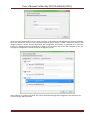
Remote configuration can be performed through several data transfer channels:
1. SMS. The terminal has a list of 4 authorized phone numbers, the messages from which are treated
as configuration commands. The commands available are described in the section "SMS enabled
settings". A phone number can be added to the list of authorized numbers either through the
Configurator, or by sending a message with the command "AddPhone".
2. GPRS. Commands can be sent from the monitoring data processing server. The format of the
commands is described in the section "Server communication protocols".
3. GPRS. Commands can be sent via the Configurator and the remote configuration server of
"GalileoSky" Ltd. In this case, the Terminal supports two parallel connections: the first – with the
monitoring data processing server, and the second – with the remote configuration server. Remote
configuration can be enabled using "RemoteConfig 1" command ("Service commands" section). It is
possible to send commands to the Terminal, to receive current information from the sensors
connected and to receive diagnostic messages, when working with the remote configuration
server. Using Configurator it is possible to create a command pack to configure the Terminal and to
save it on the server. These commands will be sent to the Terminal when it establish connection to
the server.
GalileoSky Ltd
Page 23
User’s Manual GalileoSky GPS/GLONASS (0200)
Connecting external peripherals
CAN-interface
The terminal allows to extract information from the CAN bus.
The following protocols are supported:
– J1939 (FMS). According to this protocol the Terminal is not a device transmitting to CAN bus, the device
does not change vehicle operation, it also doesn’t send confirmations to vehicle units packets and there are
no electrical noise in CAN bus. In some cases at connection to troubleshooting socket for correct
information reading from bus it is necessary to send confirmations to vehicle units packets, for this give the
terminal command ActiveCAN 1 (see CAN settings).
– J1979 (OBD ΙΙ). This protocol works according to the question-answer mode, the Terminal transmits data
to CAN bus.
Available performance modes:
J1939_SCANER – the bus scanner sending bus reports to the configurator.
FMS – standard FMS protocol filter. (see www.bus-fms-standard.com).
J1939_USER_29bit – configured user filter. Identifier length is 29 bits.
J1939_USER_11bit – configured user filter. Identifier length is 11 bits.
J19379_SCANER – the bus scanner defining bus speed and identifier capacity.
J1979_USER_29bit – standard protocol filter J1979 for 29 bits identifiers.
J1979_USER_11bit – standard protocol filter J1979 for 11 bits identifiers.
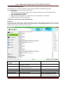
J1939_SCANER mode
Is intended to study CAN bus reports, according to protocol J1939.
Supported rates from 10000 bit/s up to 500000 bit/s (typical values: 62500, 12500, 250000, 500000).
11 and 29 bit identifiers are supported.
The scanning mode works as follows:
1. The CAN.Startscan. message is displayed;
2. CAN bus reports are displayed with a delay indicated by the CAN Regime command. (see CAN
settings).
29bit identifiers are displayed in the following format:
ID= 00000009 (8) 06 07 08 09 00 CC DD EE
where
ID - is a 29bit message identifier;
(8) - is the number of received bus bytes.
01 02 03 04 05 AA BB FF - is an 8byte message. (the lower byte is on the left, the high byte
is on the right),
11bit identifiers are displayed as
ID=009 (8) 06 07 08 09 OOCCDDEE
where
ID - is an 11bit message identifier;
(8) - is the number of received bus bytes;
01 02 03 04 05 AABBFF is an 8byte message. (the lower byte is on the left, the high byte is
on the right).
3. After all the identifiers have been displayed in the diagnostic window you can see the
CAN.Endscan message.
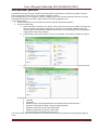
To enable this mode:
1) attach the terminal to the vehicle CAN interface;
2) in Confirugator tab Settings/CAN select bus rate and delay time (time of message waiting time);
3) push Start Scanning J1939. Received data are displayed in the right panel.
GalileoSky Ltd
Page 24
User’s Manual GalileoSky GPS/GLONASS (0200)
FMS mode
This mode is by default included in all terminals, it allows retrieving and decoding messages
corresponding FMS protocol:
total petrol consumption: the petrol the vehicle has used since it was made;
tank fuel level: in percents. 0%-empty, 100%- full;
coolant temperature;
engine revolutions;
total kilometrage.
Attention! Many car manufacturers partially support FMS or do not support it at all.
To enable this mode:
1) attach the terminal to the vehicle’s CAN interface;
2) give the CanRegime 2,25000,2000 command (see CAN settings) or in Configurator on
tab Settings/CAN select filter type FMS;
3) make sure the device receives bus data and sends them to Device tab in Configurator;
4) set the right data transmission to the server using the MainPack command (see Server
exchange protocol settings) or in Configurator tab Settings/Protocol.
J1939_USER_29bit mode
This mode enables us to receive 29bit identifiers messages from the vehicle CAN-bus, according to J1939
protocol.
To enable this mode:
1) connect the terminal to vehicle CAN interface;
2) in Configurator tab Settings/CAN select filter type Custom filter (29bit identifiers), set bus rate
and delay time or give CanRegime command with necessary parameters (see CAN settings);
3) set filers for CAN bus messages.
4) set received data sending to the server with the use of MainPack command (see Server
exchange protocol settings) or in Configurator on tab Settings/Protocol.
Notes:
1) In protocol of the first and the main packet of the terminal (Table 2. GalileoSky protocol tags) there
are 1-byte, 2-bytes and 4-bytes tags for this mode operation, i.e. if the necessary ID needs only one
byte from all data, better choose 1-byte tag.
2) Any of these tags can correspond to the right CAN message ID
Attention! The data should be recorded in the terminal in the decimal system. The hexadecimal
notation is used for convenience only.
We can choose the bytes to fill the tag from the information with this ID by means of shifting.
Let us see an example:
The CAN message identifier is ID=Ox18F00300.
We need only the first byte of all the sent content with this ID.
As we need only one byte we shall choose the tag CAN_R0 as an example.
That is the command to set the tag is as follows: CAN8BITRO ID,Shift
1) The tag number ID=Ox18FEEEOO will look as 419260256 in the decimal system.
2) The byte we need is shifted by one byte, that is the second parameter is equal to 1
So we have the following filter settings: CANBITRO 419360256,1.
Now that the message in question is passing through the bus, the first effective load byte will automatically
be placed to the tag R0 and sent to the server.
These settings are easier to make in Configurator:
1) Bus scanning;
2) Indicate identifier in the first column;
3) Select correspondent tag;
4) Visually by mouse indicate shift. Column Value will display number transmitted to the server.
J1939_USER-11bit mode is set similarly.
GalileoSky Ltd
Page 25
User’s Manual GalileoSky GPS/GLONASS (0200)
J1979_SCANER mode
This mode is used to define data transfer rate and Identifier length according to protocol J1979. If
parameters of transfer are known, it is recommended to use the J1979_29bit and J1979_11bit modes,
having specified necessary rate of the bus.
The rate of 250000 bits per second and 500000 bits per second and 11 and 29 bit identifiers are
supported.
To enable this mode:
1) connect the terminal to vehicle CAN interface;
2) push “Test OBD ΙΙ”. Received data are displayed in the right panel.
3) If scanning finished successfully, data transfer rate and Identifier length will be set automatically.
Attention! Scanning can cause failures of board equipment operation. GalileoSky Ltd bears no responsibility
for failures after CAN bus scanning.
J1979_USER_29bit mode
This mode allows to extract and decode automatically the messages with 29 bit identifiers, transferred
according to J1979 protocol:
tank fuel level: measured in percents. 0%-empty, 100%- full;
coolant temperature;
engine rpm speed |;
error codes.
Attention! Many car manufacturers partially support J1979 or do not support it at all.
To enable this mode:
1) attach the terminal to the vehicle CAN interface;
2) give the CanRegime command (see CAN settings) or in Configurator on tab “Settings/CAN “select
filter type “OBD ΙΙ 29bit”;
3) make sure the device receives bus data and sends them to Device tab in Configurator;
4) set the right data transmission to the server using the MainPack command (see Server exchange
protocol settings) or in Configurator tab Settings/Protocol.
J1979_USER-11bit mode is set analogous.
Attention! If vehicle doesn’t support J1939 protocol, J1979_USER-29bit and J1979_USER-11bit modes
operation can cause failures of board equipment operation. GalileoSky Ltd bears no responsibility for
failures after operation I this modes.
GalileoSky Ltd
Page 26
User’s Manual GalileoSky GPS/GLONASS (0200)
Device CAN-bus connection options
1. Direct connection.
CAN_H
CAN_L
GND
GNDcan
120
CANH
Vehicle
CANL
Attention! If the terminating resistor (is shown with a dotted line in the diagram) is not installed on the
vehicle side, it should be installed. Its presence can be checked with a multimeter: it is necessary to
measure the resistance between CAN_H and CAN_L with the vehicle electronics off. If the resistance is
about 60 Ohm, the terminating resistor is not needed. If the resistance is 120 Ohm, an ordinary 120Ohm
resistor should be placed between the CAN_H and CAN_L wires.
2. With current-limiting resistors
CAN_L
CAN_H
GND
1kOhm
GNDcan
1kOhm
CANH
1kOhm
CANL
Vehicle
To plug the device into the troubleshooting socket it is necessary to use the first connection option.
The second option is recommended to attach the device directly to the vehicle CAN bus.
GalileoSky Ltd
Page 27
User’s Manual GalileoSky GPS/GLONASS (0200)
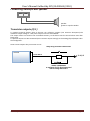
Connecting digital fuel sensors using RS232 interface
The order of connection:
1. Connect sensor’s contacts RXD, TXD and GND to terminal’s contacts TXD1, RTD1 and GND (see
Contacts description).
Attention! The device and sensor grounds must be connected!
The sensor is powered separately.
GND
RXD1
TXD
TXD1
RXD
GND
2. To set for the terminal channel RS232[1] receiving relative fuel level or frequency from the sensor. It
can be done by sending command RS2321 (see Digital inputs settings) or through Configurator tab
Settings/Digital inputs. By default all terminal channels RS232 are set to receive relative fuel level.
3. If discharges filtering is necessary adjust filter length by DFILTER command (see Digital inputs
settings) or by Configurator tab Settings/Digital inputs.
4. To set transfer of received data to the server by mainpack command (see Server exchange protocol
settings) or by Configuratot tab Settings/Protocol. These data transmission is on by default.
5. To reset the terminal by Reset command or from Configurator tab Device.
6. Make sure that the terminal receives data from the sensor. It may be done in Configurator tab
Device.
For terminals GalileoSky GPS/GLONASS v2.2.8 second sensor could be connected to zero channel RS232 by
analogy (RS2320 command is used).
If during 18 seconds the terminal receives no messages from the sensor the field RS232 comes to zero. In
this way it is possible to detect sensor rupture or failure.
GalileoSky Ltd
Page 28
User’s Manual GalileoSky GPS/GLONASS (0200)
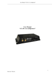
Connecting GalileoCam photocamera to the device
GalileoSky v3.0.0
GalileoSky v3.0.3 waterproof version
Data interface: RS232
Data interface: RS232
Wires:
1.
Brown: +10/30B
2.
Black: GND
3.
Blue: ТXD
4.
Whit5e: RXD
Dimensions: 45,0 х 30,0 х 15,0 mm.
Dimensions: 54,0 х 38,0 х 21,0 мм
Camera technical specifications:
- Supply voltage: 10-30V.
- Average power consumption in standby mode: 0.17W.
- Average power consumption in record mode: 0.53W.
- Operating temperature range: -30…+60ºC.
- Size: 45.0x30.0x15.0mm.
- Body material: plastic.
- Turn on time: less then 2s.
- Camera mode announcement
Optical characteristics:
- Focal distance: 4mm.
- Observation angle: 64 degrees.
- Distortion: 0,38%.
- Infrared filter: yes.
- Manual focusing: yes.
- Matrix diagonal: ¼”.
Picture characteristics:
- Color depth:24bit.
- Picture format:JPEG.
- Picture resolution: 640x480 dots and 320x240.
- Picture size: 6-65kB.
- Average picture size: 25kB
- Time of one picture receiving: 2-10s.
- Time of transmission to the server: more than 1 minute (depends on picture size and GSM connection
quality).
GalileoSky Ltd
Page 29
User’s Manual GalileoSky GPS/GLONASS (0200)
How to connect cameras via RS232 interface:
1. The camera RXD, TXD, GND should be connected to the device TXD1, RXD1, GND (see Contacts
description).
Attention! The device and photocamera grounds should be connected!
Camera has separate power supply.
2. Insert a microSD card into the device slot.
3. To make the right settings of terminal channel RS232[1] for operation with camera, give RS2321
command (see Digital inputs settings), or through Configurator tab Settings\Digital inputs.
4. Reset the terminal by Reset command or from Congifurator tab Device.
5. Make sure that the terminal operates with camera correctly, in Configurator give command
makephoto 1 (see Photocamera operation settings) and turning to Troubleshooting tab select with
ticks RS232[1] and RS232[1] detailed. When the terminal receives picture from camera,
troubleshooting displays message RS232[1].cam. rx pic. Green LED on camera rarely blinks in standby
mode, quickly – during picture transmission.
6. Take microSD card out of the terminal and evaluate picture quality. Pictures from camera connected
to zero port RS232 are saved in catalogue Pic\RS0, the first port RS232 – Pic\RS1. Separate catalogue
is created for each date, files name is formed by pictures time.
7. Reinsert the microSD card into the device slot.
Connecting RS232-RS485 adapter
Using RS232-RS485 adapter allows connecting to single RS232 up to 3 digital fuel level sensors which
operates using RS485 interface.
How to connect adapter:
1. Terminal’s contacts RXD1, TXD1, GND connect to adapter’s contacts TX, RX, GND correspondingly;
2. Adjust terminal’s port RS232[1] to operate with adapter. Send command “RS2321 9” or use tab
“Settings”\”Digital inputs” in Configurator;
3. Adjust transferring of received data to server using MAINPACK command (Server exchange protocol
settings section) or use tab “Settings”\”Protocol| in Configurator. Transferring of these data are
enabled by default;
4. Reset terminal.
Terminal supports up to 3 sensors simultaneously. Sensors must have addresses 0, 1, 2 respectively. If
within 18 seconds terminal don’t receive any message from sensor, correspondent value will set to zero.
Thereby sensor’s failure or disconnection could be troubleshooted.
GalileoSky Ltd
Page 30
User’s Manual GalileoSky GPS/GLONASS (0200)
Connecting 1Wire sensors
It is possible to attach different sensors working through 1-Wire interface, and they can operate
simultaneously.
Connecting iButton (DS1990, DS1982) identification key
There are several identification key applications:
driver identification;
trailer turning off identification;
doors opening identification.
In the same way it is possible to connect devices emulating iButton, for example, RFID-tags readers.
The terminal can support up to 8 identification keys with set identifiers or two identification keys with
random identifier. …
During identification key applying to 1-Wire and GND contacts (Contacts description) key number is entered
into the memory, point is recorded and further four lower bytes are sent to the server without checksum.
At key disconnection number turns to zero, point is recorded and message is sent to the server. Keys having
code less than 100000 are stored in iButton[1] field.
Up to eight key identifiers may be set through iButtons command (see Digital inputs settings) or in
Configurator on tab Settings\Digital inputs. Lower 4 bytes of iButton key number should be entered without
checksum in hexadecimal system.
For example, full hexadecimal key number:
09 00 00 00 91 02 0С 5С, where
09 – kind of device (in this case DS1982, for DS1990 is 01),
00 00 00 91 02 0С – unique number,
5С – checksum.
In this case 00 91 02 2С should be entered.
At identification key applying with one of set identifiers, correspondent bit is set in field iButton connection
status. You may control it on tab Device in Configurator.
Connecting DS18S20 (DS1820, DS18B20) thermometers and temperature
and humidity sensors (DS1923)
It is possible to attach up to 8 thermometers DS18S20 and 8 humidity sensors DS1923. To use the sensors
connect them to 1-Wire and GND contacts (Contacts description) and activate the corresponding protocol
items (Server exchange protocol settings, Table 2, GalileoSky protocol tags). There is not any linkage
between a thermometer or humidity sensor and a certain tag cell. All thermometer data are stored in
memory cells in a definite order: from a lower tag to a high tag. If the number of cells exceeds the number
of thermometers, the extra high cells will contain data corresponding to sensor disconnection.
At temperature sensor turning off the thermometer field shows disconnection (-128ºC).
At humidity sensor turning off the thermometer field shows disconnection (0%).
GalileoSky Ltd
Page 31
User’s Manual GalileoSky GPS/GLONASS (0200)
GalileoSky Ltd
Page 32
User’s Manual GalileoSky GPS/GLONASS (0200)
Connecting Autoinformer speaker
Vol1
Vol2
Speaker
greater or equal to 8 Ohm
Transistor outputs (0/1)
To operate external devices there 3 discrete «on collector» outputs (see Contacts description).The
maximum output voltage is -+30V, each output current is within 80mA.
The output values are stored in the nonvolatile memory, so the device sets the stored values even after
being reset.
To operate outputs use Out command (see Transistor output settings) or the Settings/Input/Output tab in
the Configurator.
OUT0…OUT2 outputs relay connection circuit
Relay wiring and other inductive load
GALILEO
OUT0..OUT2
+( 12..30 ) В
1N5402..1N5408 diode
or analogous for 3 А direct current and
reverse voltage within 200 v
GalileoSky Ltd
Page 33
User’s Manual GalileoSky GPS/GLONASS (0200)
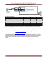
Connecting audio equipment and push-to-talk Tg V1.x
Mic0
Spkr0
0
Mic1
Spkr1
AGND
Sound cable’s shield
Electret
microphone
Microphone specifications
Parameter
Operating voltage, V
Operating current, uA
Load resistance, kOhm
Speaker specifications
Parameter
Connected speaker resistance, Ohm
Operating current, mA
Power with a 32Ohm speaker, mW
Min. value
70
1.2
Min. value
8
Mean value
1.60
Max. value
2.2
300
2.2
Mean value
Max. value
+-250
250
There is an opportunity to connect push-to-talk Tg V1.x. It is produced by GalileoSky Ltd and has special
adapter for connecting to terminal.
How to connect adapter:
1. Adjust zero input (IN0) to measure mean value. It can be done on “Settings”\”Inputs\Outputs” tab in
Configurator or by using InCfg0 command (Discrete-analog input setting section);
2. Disable autoanswer. It can be done on “Settings”\”Sound” tab in Configurator or by using
Autoanswer command (Voice communication settings section);
3. Enable tush-to-talk support. It can be done on “Settings”\”Sound” tab in Configurator or by using
Tangenta command (Voice communication settings section).
Incoming call leads speaker to beep. Pick up can be done by pressing push-to-talk’s button once. Further
switching between push-to-talk’s microphone and speaker can be done by pressing push-to-talk’s button.
When the button is pressed the microphone is enabled, when the button is released the speaker is
enabled.
GalileoSky Ltd
Page 34
User’s Manual GalileoSky GPS/GLONASS (0200)
Connecting GLONASS accessory
GLONASS accessory can be connected to GalileoSky GPS to zero RS232 channel only.
How to connect:
1. Connect terminal and accessory using the cable from accessory’s package;
2. Carefully screw GLONASS aerial to accessory.
Attention! GLONASS accessory must be packaged by GLONASS aerial only!
3. Adjust terminal’s zero channel RS232[0] to operate with accessory. It can be done by sending
“RS2320 3” command (Digital inputs settings section) or by using “Settings”\”Digital inputs” tab in
Configurator;
4. Set second output in open state by sending “out 2,0” command (Transistor output setting section)or
by using “Setting”\”Digital inputs” tab in Configurator;
5. Reset terminal by sending “Reset” command or using “Device” tab in Configurator;
6. Make sure that the terminal operates properly with accessory. In this case Configurator’s tab
“Device” will display coordinates, which navigation data’s source is GLONASS.
There are two operation modes:
1. Operate with GLONASS accessory only. It can be archived by screw off GPS aerial from the terminal;
2. Concurrent operation of GLONASS aerial and internal GPS unit (GPS aerial must be screwed on).
Disadvantages of the first mode are:
In case of low visibility (rain, heavy snowfall) GLONASS accessory can be received no necessary
minimum navigation information, as a result the part of the track can be lost;
In case of connection GLONASS accessory to on-board network instead of car’s battery the
GLONASS unit will be switched of together with the car.
The second mode is necessary that in case of low visibility of GLONASS satellites (or it scarcity) terminal
switches on alternate navigation data source – GPS. Both units (GLONASS and GPS) are enabled during
operating. The analysis of coordinate’s accuracy which is received from both units take place. Terminal
chooses the most accurate system immediately.
Equal status leads to GLONASS unit will be chosen.
Connecting REP-500 electricity meter
The REP-500 is an electricity meter which can be connected to the Terminal via RS232 interface. To connect
the REP-500, perform the following steps:
1. Connect respectively the RXD1, GND contacts of the Terminal with TX, Ground of the REP-500.
2. In the Terminal, configure the RS232[1] port for operation with the meter. This can be performed
using the command "RS2321 10" or via the Configurator on the tab "Settings"\"Digital inputs".
3. Reset the Terminal.
4. Set the transfer of counter measurements to the server with the command "MainPackBit 171,1".
GalileoSky Ltd
Page 35
User’s Manual GalileoSky GPS/GLONASS (0200)
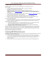
Connecting passenger flow registration sensors Ш2
The terminal supports connection up to 8 Ш2 sensors through 4 discrete analogue-inputs (DAI) IN0-IN3
(Contacts description section).
Connection order of one Ш2 sensor through resistor to one DAI inputs of the terminal.
To connect 2 Ш2 sensors to one of DAI use divisor on two resistors. Calculation principle is realized on
voltage level change at sensors triggering.
V – power supply (battery/ vehicle power supply);
R1, R2 – resistors;
Ш2_1, Ш2_2 – passenger flow registration gauges Ш2.
Connection order of 2 Ш2 sensors through resistors to one DAI inputs of the terminal.
Set input to pulse count from two sensors through the Configurator or by command incfg0 3,2,X,X,Y,Y
(where Y – one sensor triggered; X – two sensors triggered).
Parameter X and Y depending on supply voltage and R1,R2 resistors resistance takes different values, for
example:
U(v)=12, R1=10k, R2=10k, then X=3500, Y=7921
U(v)=12, R1=14k, R2=14k, then X=3000, Y=7000
U(v)=24, R1=10k, R2=10k, then X=7000, Y=15842
U(v)=24, R1=14k, R2=14k, then X=6000, Y=14000
It is calculated by formula:
(
)
(
)
Attention! To avoid false operation at sensors connection and further operation use stable voltage power
supply.
Terminal operation result will be pulse fronts count from each sensor, i.e. when one person passes one
door total pulse number increases by 2. Correspondingly to count passengers number passed through
sensors divide pulse count result by 2.
GalileoSky Ltd
Page 36
User’s Manual GalileoSky GPS/GLONASS (0200)
Connecting Garmin navigators supporting FMI protocol
The terminal can serve as gateway for Garmin FMI protocol packets transmission to the server and back.
Garmin FMI protocol allows:
drivers identification by code number (driver enters his/her number into navigator, the number is
transmitted to the server);
driver status transmission to the server (driver selects his/her status on navigator display);
text messages exchange between Garmin navigator and the server;
transmission from the server to navigator route end points (in this case navigator calculates
optimum way to the set points and displays it on the map);
speeding control and the server informing about it;
geographical areas transmission from the server to navigator and displaying them.
Protocol abilities description can be found on http://www8.garmin.com/solutions/pnd .
The terminal only transmits packets from navigator to the server and back, so packets are analyzed at the
server.
To connect Garmin navigator:
1. Purchase interface cable Garmin FMI (for example, Garmin FMI 10), cable is chosen according to the
navigator model. Cable has from one side mini-USB socket to connect to navigator, from the other
side – supply and interface RS232 contacts.
2. Connect interface RS232 contacts to the terminal zero port RS232; RX cables to the terminal TXD0; TX
cables to the terminal RXD0; obligatory connect contact GND RS232 cable to the terminal GND.
3. Connect cable supply.
4. Connect cable to navigator.
5. In the terminal set RS232[0] port for operation with navigator. It could be done by command
RS2320 5 or through the Configurator on tab Settings\Digital inputs.
6. Reset the terminal.
To make sure that the terminal and navigator connection works properly select in troubleshooting
messages from necessary port RS232. If connection is correct messages periodically will displayed
RS2320. Garmin FMI. Enable FMI.
RS2320. Garmin FMI. ACK.
If connection is right, the navigator interface changes, left-hand icon turns into truck, it gives access to
messages sending and receiving functions.
By analogy navigator can be connected to first RS232 port.
Simultaneous connection of two navigators is not supported.
Connecting course detector Trimble
Course detector Trimble can be connected to GalileoSky GPS to zero RS232 channel only.
How to connect:
1. Adjust course detector to send NMEA-messages GGA, RMC, VTG 57600 bit/s, no parity, 8 bit in byte;
2. Connect course detector’s RS232 contacts to zero RS232 channel’s contacts: cable’s RX to terminal’s
TXD0, cable’s TX to terminal’s RXD0, be sure to connect cable’s GND to terminal’s GND;
3. Adjust terminal’s RS232 port to operate with course detector. It can be done by “RS232 8” command
(Digital inputs settings section)or by using “Settings”\”Digital inputs” tab in Configurator$
4. Reset the terminal.
There are two operation modes:
1. Operate with course detector only, when GPS aerial is screwed off;
2. Concurrent operation of course detector and internal GPS unit (GPS aerial must be screwed on). The
analysis of coordinate’s accuracy which is received from both units take place. Terminal chooses the
most accurate system immediately. Equal status leads to course detector will be chosen.
Connecting two or more course detectors is not supported.
GalileoSky Ltd
Page 37
User’s Manual GalileoSky GPS/GLONASS (0200)
Connecting CAN-LOG
Device CAN-LOG is used for CAN bus data reading. It allows to get data about:
- total time of engine work
- total kilometerage of vehicle
- whole fuel consumption of vehicle
- fuel level in % or liters
-
engine speed;
coolant temperature;
- vehicle speed
- axle load
CAN-LOG support was added to secure compatibility with installed board equipment. At initial
installation it is recommended to use the built-in functions for CAN bus operation (CAN interface).
Advantages of using built-in functions of the device:
- no extra costs
- possibility of scanning CAN bus
- possibility of reading all the data of CAN bus, and not just listed for CAN-LOG
Connection of CAN-LOG:
1. Connect correspondingly contacts RXD1, TXD1, GND and RS232 TX, RS232 RX, CAN-LOG’s
mass.
2. Set RS232[1] port for operation with the navigator In the Terminal . It can be done by command
“RS2321 5” or through the Configurator on tab “Settings”\”Digital inputs”.
3. Disconnect the Terminal built-in functional for operation with CAN bus. It can be done by
command CANREGIME 0,250000,2000 or through Configurator “Settings”\”CAN” tab .
4. Specify the parameters transferred to the server (Table 2. GalileoSky protocol tags). Also the
MAINPACK OR HEADPACK commands can be used (see Server exchange protocol settings) or in
through Configurator ”Settings”/”Track” tab.
5. Reset the terminal.
For terminals GalileoSky GPS/GLONASS v2.2.8 CAN-LOG could be connected to zero channel RS232 by
analogy (RS2320 command is used).
Concurrent operation with two CAN-LOG devices is not supported
Connecting CUB5B indicator
CUB5B indicator is a segment 8-bit indicator, which can be connected to the Terminal using RS232
interface. It can display current sensors data; CAN bus data, mileage and so on. Information updates
every second.
Connection:
1. If indicator was set for operation with other equipment, it is necessary to reset to factory
settings. If indicator is new, it is unnecessary.
2. Connect correspondingly Terminal contacts RXD1, TXD1, GND and TX, RX and CUB5B
ground.
3. Set RS232[1] port for operation with indicator in the terminal, it can be done by command
“RS2321 7” or through the Configurator on “Settings”\”Digital inputs “ tab.
4. Choose the displayed parameter, it can be done by CUB5 command or through the Configurator
on “Settings”\”Digital inputs” tab.
5. Reset the terminal.
For terminals GalileoSky GPS/GLONASS v2.2.8 CUB5B could be connected to zero channel RS232 by analogy
(RS2320 command is used). In this case terminal supports simultaneous operation with 2 indicators.
GalileoSky Ltd
Page 38
User’s Manual GalileoSky GPS/GLONASS (0200)
Connecting weight indicator CI5010A
The weight indicator CI-5010A is designed to measure, control and indicate electrical signals produced by
weight measuring resistance strain gages. It can be connected to the Terminal via interface RS232.
Procedure of CI-5010A connection:
1. Adjust the indicator to constant indication of measure value.
2. Connect the contacts RXD1, TXD1, GND of the Terminal with TX, RX, Ground CI-5010A respectively.
3. Adjust the port RS232[1] in the Terminal to operation with the indicator. It can be performed by the
command RS2321 12 or via the configuration tool in the tab "Settings\Digital inputs".
4. Reset the Terminal.
In a similar way one can adjust connection of CI-5010A to the port RS232[0] of the Terminal GalileoSky GPS
and GalileoSky GPS/GLONASS v2.2.8. In this case concurrent operation of 2 indicators is supported.
Data from the indicator are rounded up to a whole number. Maximum value that the Terminal can handle
is 65535.
GalileoSky Ltd
Page 39
User’s Manual GalileoSky GPS/GLONASS (0200)
Configurator
Configurator is a PC program allowing us
to configure the device via graphic interface and with the help of commands;
to troubleshoot the device saving results to a log-file;
to see the device units state in real time;
to copy monitoring data to a file from the internal memory and SD card;
to send the copied data to the server;
to specify autoinformer’s areas.
32 and 64 bit OS are supported: Windows 2000, Windows XP, Windows Vista, Windows 7, Windows 8.
It is possible to configure and troubleshoot terminal as connected locally by USB as connected remotely by
GPRS. There is no need to reconfigure terminal which connected by GPRS. PC with installed Configurator
must not have static IP-address.
Program installation and running
Download the Configurator program from the site and launch it.
Attention! Program installation may require changes of crucial OS elements. Do not let your antivirus
program block the installer operation.
In case of a security system warning confirm launching the program.
During the installation old drivers will be deleted and new drivers will be installed. Installation of the fullfunction or limited version of the Configurator is possible. The latter allows to unload archive and to receive
the current parameters of sensors, but not to change settings.
Start the Configurator program (from Start menu\Programs\GalileoSky\Configurator). Turn the power on
and attach the device to the computer via a USB cable.
After the terminal connection the program automatically copies all the device settings parameters. If the
program identifies the device, all the buttons on the vertical left-hand panel will be active.
GalileoSky Ltd
Page 40
User’s Manual GalileoSky GPS/GLONASS (0200)
Device tab
Displays information about the device state and allows resetting the device. This tab contains the terminal
model, oriented in space according to accelerometer indications. Model is rotated by mouse. Parameter
values which are beyond limits, wrong coordinates and exceeding of maximum incline angle are shown in
red.
If there is a PIN code in the device, the program will request it to access the settings. At wrong code
entering the terminal disconnects from computer, resets, connects to the Configurator again and waits for
the right code enter.
For remote configuration and diagnostics of the Terminal, click "Select device..." button. In the window
appeared, enter your login and password to get the access to the remote configuration server. The login
and password can be obtained by the "GalileoSkay" Ltd. technical support team or by clicking the "Register
new user" button under input fields.
GalileoSky Ltd
Page 41
User’s Manual GalileoSky GPS/GLONASS (0200)
After successful authorization on the server, the form of terminal list management will become available.
After first connection, the list of the controlled terminals will be empty. To add a Terminal to the list, click
"Register Device" button. During registration the Configurator will request a password for a particular
Terminal, a default password corresponds to IMEI of the Terminal; this can be later changed by the user
through the Configurator. Terminals may be arranged in groups.
After selection of a specific Terminal, this can be controlled through the Configurator, the same way as it
occurs with the USB connection.
GalileoSky Ltd
Page 42
User’s Manual GalileoSky GPS/GLONASS (0200)
Troubleshooting tab
This tab allows us to see the current device state through the device troubleshooting reports.
The troubleshooting mode has the following buttons:
1) Start /Stop
With a 10 sec interval the time scale displays information about the server connection, packet
recording, updating coordinates etc.
2) Clear troubleshooting window
3) Save troubleshooting results to a log-file which can be opened by any text editor
4) Search through troubleshooting history
GSM unit troubleshooting information
Attention!
If the service has already been registered by the terminal, another GPRS connection is only possible
through switching off the GSM modem (troubleshooting report: sim300gotopowdown). That is no money
will be lost due to the minimum paid time interval.
Troubleshooting
messages
GSM. Success turn on.
GSM. Not success turn
on!
GSM. Success init.
GSM. Not success init!
GPRS. Activated.
GPRS. Not activate.
GalileoSky Ltd
Description
GSM unit powered.
Turning on successful.
GSM unit powered.
Turning on denied by unit.
GSM unit activated.
GSM unit activation failed.
GPRS successfully activated.
GPRS activation failed.
Possible causes
GPRS is not activated on this SIM
card. Not enough money in the
account. GSM network overloaded.
Page 43
User’s Manual GalileoSky GPS/GLONASS (0200)
GPRS. Success connect
to server.
GPRS. Not success
connect to server.
GPRS. Reconnect
Number=#
GPRS. Firstpack OK.
GPRS. Firstpack
False.[0]
GPRS. Firstpack
False.[1]
Device server connection successful
Device server connection failed
Number of server reconnections.
# - reconnection number
First packet sent to server
The device has sent the first packet, but
there is no confirmation in terms of
TCP/IP.
The device has sent the first packet, but
there is no confirmation in terms of the
application.
Server access denied or wrong
server settings for the device.
GSM network overloaded. The
packet has been blocked by device
firewall.
GSM network overloaded. The
server is not handling the first packet
SMS troubleshooting information
Troubleshooting message
SMS. RX SMS.
SMS. TelNum: +79112299922
Command: ID
SMS. TX OK.
SMS delfromslot 1
Not reply SIM. Slot 1
GSM. No SIM-card
Description
New SMS message received
received from a given phone number
ID command received
Message successfully sent
delete handled SMS ( from SIM card first slot)
no SIM card reply (from SIM card first slot)
no SIM card reply (the card is most likely not inserted)
Internal Flash memory troubleshooting information
Troubleshooting message
MEM. Inp-s
MEM. Turn,dist
MEM. Time
MEM. Write point - 200
Description
Point record reason is inputs state change;
Point record reason is change of distance between previous and new
place or angle of motion direction;
Record reason is time;
Write point with ordinal number 200 is recorded.
GPS-unit troubleshooting information
Troubleshooting information
SAT. Coord refresh.
SAT. Coord not refresh.
SAT. Temper is low than -40
SAT. Temper is high than 65
SAT. Time out. Restart MCU.
GLONASS. Message received.
Len = 401
GPS. Message received. Len =
172
GPS. Change baud rate = 1
SAT. Fix = 1
SAT. SatlnUse = 7
SAT. Valid = 1
GalileoSky Ltd
Description
Current record coordinates updated by GPS
unit. Vehicle considered to be moving, packet
has not been filtered off.
Current record coordinates not updated.
Filtering off while parking activated.
Device temperature is lower than -40ºC. Unit
operation at lower temperatures is impossible.
Device temperature is higher than +65ºC. Unit
operation at higher temperatures is impossible.
No GPS data for 60 seconds. Device reset.
Possible causes
GPS unit out of order.
GPS unit failure.
Device received information from GLONASS
unit. 401 byte received.
Device received information from GPS unit. 172
byte received.
Attempt to set GPS unit rate. Attempt № 1.
Current position fixed (0 – not fixed);
7 satellites are used for navigation;
Coordinates are right (they can be used for
location determination). This Valid has nothing
common with valid in packet and status.
Page 44
User’s Manual GalileoSky GPS/GLONASS (0200)
Galileo uses GLONASS
Galileo uses GPS
SAT. Incorrect data from
GLNS/GPS module
SAT. Time out. Restart MCU
SAT. High Speed = 200
Terminal uses GLONASS system.
Terminal uses GPS system.
Wrong data received from the used unit
(probably due to processor overload)
Device gets no data from receivers (GLNS/GPS)
Navigation speed data filter turns on (this data
will be skipped by the unit).
SAT. HDOP is high = 6
Navigation HDOP data filter turns on (this data
will be skipped by the unit).
SAT. Jump = 5000
Navigation coordinate data filter turns on (leap
to large distance occurred).
SAT. First start OK. Sat count
At the terminal turning on the unit must get
>= MIN
more than MIN satellites (only then data is
reliable).
Other troubleshooting messages are not described, but they have intuitive names. If there are any
questions, you will find the answer at our forum.
GalileoSky Ltd
Page 45
User’s Manual GalileoSky GPS/GLONASS (0200)
Command mode tab
This tab is intended to run single command or a set of commands.
The command mode has the following buttons:
1) Run commands;
2) Run single command;
3) Open from file;
4) Save to file.
The commands will be identified whether you use capital or lower-case letters or both in turn.
Attention!
There are no spaces in command name!
Spaces between parameters are not allowed!
Commands and parameters are separated by space.
Commands are separated by Enter.
Single command example
An example of a parametric command
Enter APN internet.beeline.ru,beeline,beeline as shown on the figure above and press
Run single command. The command and response will be displayed in the Responses window.
Command: APN internet.beeline.ru,beeline,beeline
Response: GPRS: APN=INTERNET.BEELINE.RU, user=BEELINE, pass=BEELINE
To access parameters in the device memory you should use a command without parameter!
A example of command without parameter:
"APN" command
Request: APN
Response: GPRS:APN=INTERNET.BEELINE.RU,user=BEELINE,pass=BEELINE
GalileoSky Ltd
Page 46
User’s Manual GalileoSky GPS/GLONASS (0200)
Set of commands example
Enter in necessary commands in Command window, each starting a new line, as shown on the figure below
and press the Run commands button.
Example: Serverip 55,34,76,123,30100
ID 6299
HeadPack 1110
The given commands and results will be displayed in the Command results window.
Command: Serverip 55,34,76,123,30100
Response: ServerIp=55.34.76.123:30100
Command: ID 6299
Response: ID: 6299
Command: HeadPack 1110
Response: HeadPack = 0000000000000000000000000000000000000000000000000000000000001110b
GalileoSky Ltd
Page 47
User’s Manual GalileoSky GPS/GLONASS (0200)
Saving and downloading parameter set
To quickly configure several devices with the same set of commands it is recommended that commands
should be run from a pre-saved file. To do this, enter a list of commands to the command window. Make
sure whether they are typed in correctly by pressing the Run commands button and press Save to file.
In the opened window you will
be offered to save the file in log
configurator directory.
Type file name and push Save
button as shown on the figure
The file will be saved in log configurator directory. Then press Open from file… button.
Select the necessary file and
push Open button, as shown in
the figure.
For simultaneous running of several commands push Run commands button.
To run one command it is necessary to move to it in Commands window and push Run single command
button.
GalileoSky Ltd
Page 48
User’s Manual GalileoSky GPS/GLONASS (0200)
Graphic user interface settings
All the main settings are situated in tabs in the program upper part.
Security
This tab allows to set SIM-cards PIN code, phone authorization password, list of authorized phone
numbers and encryption key for data transfer to the server.
Data transmission
This tab allows to set SIM-card PIN code, APN for Internet connection, monitoring data processing servers,
packets data transmission and international roaming.
GalileoSky Ltd
Page 49
User’s Manual GalileoSky GPS/GLONASS (0200)
Protocol
The device has its own data transmission protocol developed by GalileoSky Ltd.
During device operating and data sending to the server, the following stages are possible:
1) Establishing a TCP/IP connection (does not need additional settings);
2) Sending connection data described in the Head packet column (the data to be sent to the server
are marked in the first column);
3) If the device has gone through the first two stages, it starts sending accumulated packets according
to format described in the Main packet column.
To send data the modem establishes a server link and keeps it active even after sending the packet. It is
done to save server connection traffic used to establish connection.
GalileoSky Ltd
Page 50
User’s Manual GalileoSky GPS/GLONASS (0200)
Power saving
This tab allows to set shutdown options of the Terminal units at stop, to reduce power consumption.
GalileoSky Ltd
Page 51
User’s Manual GalileoSky GPS/GLONASS (0200)
Track
This tab allows to set archive saving place and periods of coordinates recording at stops and in motion,
details of track and filtering false coordinates.
The device filters coordinates by speed, acceleration, passed distance, horizontal accuracy, satellites
number.
In addition the terminal allows filtering of coordinates taper during stops by supply voltage at vehicles
battery (Mhours command).
Parameters:
supply voltage at stopped engine;
supply voltage at started engine;
The first parameter is selected in the following way:
1) engine is stopped for 5 minutes;
2) Vpit voltage parameter is saved in Device tab.
The second parameter is selected in the following way:
1) engine is started;
2) Vpit parameter is saved;
3) mhours command parameters are filled and sent to the terminal.
When engine is started, the 9th bit is set in the device status (Table 3. Device status field explanation).
Each terminal is equipped with accelerometer which allows filtering coordinates taper during stops based
on vehicles vibration.
Parameters:
Sensitivity– conventional unit, where 600 units sensitivity corresponds to 1g (gravitational
acceleration)
Time parameter. This filter is enabled when there is no vibration within a predefined time
period. The filter operates until the necessary amplitude acceleration is reached.
GalileoSky Ltd
Page 52
User’s Manual GalileoSky GPS/GLONASS (0200)
Inputs/Outputs
For input’s operation’s principles see Discrete analog input (DAI) operation.
For discrete inputs’ description see Transistor outputs (0/1).
GalileoSky Ltd
Page 53
User’s Manual GalileoSky GPS/GLONASS (0200)
Digital inputs
This option allows to choose the type of peripherals connected to RS232 inputs, to set iButton keys, to
adjust periodical photocamera shooting.
Sound
This option allows to set a microphone and sound gain via a GSM channel, number of calls before they are
answered by the device, autoinformer performance parameters.
GalileoSky Ltd
Page 54
User’s Manual GalileoSky GPS/GLONASS (0200)
Signaling
This option allows to set device response to input state, speed and coordinate change, telephone numbers
for SMS or telephone call in case of signaling activation. Shock and incline determination is also can bу set
here.
CAN
This option allows to set CAN filter and to scan CAN bus for identifiers being used.
After pressing Listen scan the CAN scanner will be activated and received messages will be displayed in the
right-hand panel. When scanning is completed it is possible to set tags in the protocol where bus data to be
sent. To do this CAN identifier and tag should be chosen and the message part to be sent should be
selected. To remove the filter the corresponding message identifier should be selected and erased.
GalileoSky Ltd
Page 55
User’s Manual GalileoSky GPS/GLONASS (0200)
Geographical areas
On this tab it is possible to set list of geographical areas and the terminal operation inside and outside
them.
GalileoSky Ltd
Page 56
User’s Manual GalileoSky GPS/GLONASS (0200)
Transferring and sending data
Data transfer from device to file
This option allows to transfer data from the internal memory or SD-card to computer files via a USB cable.
In the former case one InternalFlash.csv file is created, in the latter there will be several files sorted by
dates in the same way they are stored on the card.
Data transfer from the internal memory can be stopped and resumed; data transfer from the SD card can
be stopped only by disconnecting the USB cable.
Sending data to server
This option allows to send data previously transferred from the device to any server emulating the device
GalileoSky protocol. To send it the IP address and server port must be specified and the file or catalogue to
be sent must be chosen. If a catalogue is chosen, the program will send all its data files. The process can be
stopped and resumed.
GalileoSky Ltd
Page 57
User’s Manual GalileoSky GPS/GLONASS (0200)
Routes for autoinformator
On this tab there is a graphic editor of zones of autoinformator (see Autoinformator function).
Internet access is required to display the map.
To edit zone:
1) Insert Micro-SD card in computer, chose the disk in the drop-down list. The route list and track list
will be loaded automatically.
2) Choose edited route or create new one by button “+” to the right of route list. All stops will be
loaded automatically, the map being moved to the first stop.
3) Edit zone parameters. It can be done on the right panel as well as visually by moving red points.
4) Create new zones. Press the button “+” to the right of stops list. New zone appears in the middle of
the map, then it can be edited.
5) Choose audio track for zone. It can be done in the drop-down list “Audio track”, or new file can be
loaded by button “+” to the right of stops list. Formats wav,mp3, ogg, raw, gsm are supported.
Configurator converts file in format appropriate for Terminal and copies it on the micro-SD card.
6) Press “Save route” to save changes on the micro-SD card.
To make sure all zone are correct, load track after trip. Configurator supports Terminal memory csv-tracks
or tracks stored on the micro-SD card.
GalileoSky Ltd
Page 58
User’s Manual GalileoSky GPS/GLONASS (0200)
Trusted iButton keys
This tab contains the editor of a trusted iButton keys list.
The list is stored on a microSD card; to edit the list, perform the following:
1. Remove the microSD card from the Terminal.
2. Insert the microSD card in the computer and select the disk from a drop-down list; the list of trusted
iButton keys will be loaded automatically.
3. Keys may be entered either in decimal or in hexadecimal form; the corresponding value in another
column will be converted automatically.
4. Click "Save to disk" to save the changes to the microSD card.
The list of keys is stored in the "keys.bin" file; it can be copied and used in microSD cards of other
Terminals.
GalileoSky Ltd
Page 59
User’s Manual GalileoSky GPS/GLONASS (0200)
Commands list
To request a current parameter(s) value you need run command without parameter.
SMS management enabling settings
Command format
Parameters
Explanation
Example
AddPhone xxxx[,n]
xxxx - is a 4 digit password, 1234 by default
n – slot number (0-3) where telephone number will be saved.
While using a mobile to make settings it must first be authorized with the above
command. Up to 4 telephone numbers can be authorized.
Request: AddPhone 1234
Reply: Phones (0) = 890101243456 (1) = (2) = (3) =
Command format
Parameters
Explanation
Example
ChangePass aaaa
aaaa - is initial four-digit password;
Changing and viewing current password.
Request: ChangePass 5678
Reply: Password changed to ‘5678’
Command format
Parameters
Explanation
Example
Phones P1,P2,P3,P4
P1,P2,P3,P4 – authorized phone numbers written in international format
Getting list of authorized phones
Request: Phones +7901012345,,,
Reply: Phones (0)=+790101243456 (1)= (2)= (3)=
Data transmission settings
Command format
Parameters
Explanation
Example
Command format
Parameters
Explanation
Example
Command format
Parameters
Explanation
Example
GalileoSky Ltd
APN a,u,p
a – access point name
u – user
p – password
Access point settings for SIM0
Request: APN internet.beeline.ru,beeline,beeline
Reply: GPRS:APN=internet.beeline.ru,user=beeline,pass=beeline
OPS0 n1,n2,n3,n4,n5,n6,n7,n8,n9,n10,n11,n12,n13,n14,n15
n1-n15 – GSM-networks connection to which is preferred.
A list of the GSM-nets preferred for SIM0. The net is defined by a mobile country
code and a mobile operator code (the list of codes is given at
http://www.itu.int/dms_pub/itu-t/opb/sp/T-SP-E.212A-2010-PDF-E.pdf), for
example, the Russian Federation area code is 250.
Request: OPS0 25001,25099
Reply: OPS0:25001,25099,,,,,,,,,,,,,;
OPS1 n16,n17,n18,n19,n20,n21,n22,n23,n24,n25,n26,n27,n28,n29,n30
n16-n30 – GSM-networks connection to which is preferred..
A list of the GSM-networks preferred for SIM0. The network is defined by a
mobile country code and a mobile operator code (the list of codes is given at
http://www.itu.int/dms_pub/itu-t/opb/sp/T-SP-E.212A-2010-PDF-E.pdf), for
example, the Russian Federation area code is 250.
Request: OPS0 25001,25099
Reply: OPS0:25001,25099,,,,,,,,,,,,,;
Page 60
User’s Manual GalileoSky GPS/GLONASS (0200)
Command format
Parameters
Explanation
Example
Serverip host,port
host – is server domain name or its IP-address;
port – is server port.
Old command syntax is also supported for indication of IP-address:
Serverip ip1,ip2,ip3,ip4,port
ip1, ip2, ip3, ip4 - is IP server address.
Main server parameters where monitoring data transmitted.
Start from firmware 92
Request: Serverip m.7gis.ru,60521
Reply: SERVERIP=m.7gis.ru:60521
Request: Serverip 46.146.233.216,60521
Reply: SERVERIP=46.146.233.216:60521
All firmware
Request: Serverip 46.146.233.216,60521
Reply: SERVERIP=46.146.233.216,60521
Command format
Parameters
Explanation
Example
Command format
Parameters
Explanation
Example
Serverip2 ip1,ip2,ip3,ip4,port
host – is server domain name or its IP-address;
port – is server port.
Old command syntax is also supported for indication of IP-address:
Serverip2 ip1,ip2,ip3,ip4.port
ip1, ip2, ip3, ip4 - is IP server address.
Additional server parameters.
Request: Serverip2 m.7gis.ru,60521
Reply: Serverip2=m.7gis.ru:60521
ServersCfg t
t – time of connection with one server, [sec]. If equal to 0 data are transmitted
only to the main server.
Sets server connection session time.
Request: ServerСfg 120
Reply: SERVERCFG:SeansTime=120;
Command format
Parameters
Explanation
Example
ID n
n is terminal number
Changes device number.
Request: ID 123
Reply: ID=123
Command format
Parameters
Roaming MCC_MNC,Size,Interval
MCC_MNC – mobile code of the country where data can be transmitted without
limitations (codes list is given in http://www.itu.int/dms_pub/itu-t/opb/sp/T-SPE.212A-2010-PDF-E.pdf ), for example Russian Federation code is 250. Zero means
that special roaming settings are not used;
Size – maximum number of bytes which can be transmitted during one
connection session in roaming, with 0 only the first packet is transmitted;
Interval – communications interval in hours.
Data transmission settings in international roaming.
Request: Roaming 250,10000,24
Reply: ROAMING:Home=250,MaxBytes=10000,Interval=24;
Explanation
Example
GalileoSky Ltd
Page 61
User’s Manual GalileoSky GPS/GLONASS (0200)
Server exchange protocol settings
Command format
Parameters
Explanation
Example
Command format
Parameters
Explanation
Example
Command format
Parameters
Explanation
Example
Command format
Parameters
Explanation
Example
Command format
Parameters
Explanation
Example
GalileoSky Ltd
HeadPack bbbbbbbbbbbbbb
bbbbbbbbbbbbbb is tag set from 0 to 127
if b is replaced by 1,the tag is on.
If b is replaced by 0, the tag is off.
Tag numeration order is given in Table 2 GalileoSky protocol tags.
Head packet configuring.
Request: HeadPack 1110
Reply: HeadPack=
0000000000000000000000000000000000000000000000001110b ,
which means that tags from the second to the fourth inclusive are on and the first
and the rest tags inclusive are off.
HeadPack2 bbbbbbbbbbbbbb
bbbbbbbbbbbbbb is tag set from 128 to 255
if b is replaced by 1,the tag is on.
If b is replaced by 0, the tag is off.
Tag numeration order is given in Table 2 GalileoSky protocol tags.
Head packet configuring.
Request: HeadPack2 110000
Reply: HeadPack2=110000b,
Which means that tags 128, 129, 130, 131 are on, tags 132, 133 are on.
All the next following tags are off.
HeadPackBit index, value
index – is tag number, which will be on or off for transmitted on server
value – 1 if tag should be transmitted on server
0 if tag should not be transmitted on server
Tag numeration order is given in Table 2 GalileoSky protocol tags.
Head packet configuring.
The second tag is on:
HeadPack=1100b
Switch on this tag.
Request: HeadPackBit 2,1
Reply: HeadPack=1100b
MainPack bbbbbbbbbbbbbb
bbbbbbbbbbbbbb – is tag set from 0 to 127
if b is replaced by 1, the tag is on.
if b is replaced by 0 the tag is off.
Tag numeration order is given in Table 2 GalileoSky protocol tags.
Main packet configuring.
Request: MainPack 11111111111111111111110000
Reply: MainPack= 00000000000000000000011111111111111111111110000b
Which means that tags 1, 2, 3, 4 are on and tags 5-26 inclusive are off. All the next
following tags are off.
MainPack2 bbbbbbbbbbbbbb
bbbbbbbbbbbbbb – is tag set from 128 to 255
if b is replaced by 1, the tag is on.
if b is replaced by 0 the tag is off.
Tag numeration order is given in Table 2 GalileoSky protocol tags.
Main packet configuring.
Request: MainPack2 110000
Reply: MainPack2=110000b,
Which means that tags 128, 129, 130, 131 are on, tags 132, 133 are on.
All the next following tags are off.
Page 62
User’s Manual GalileoSky GPS/GLONASS (0200)
GalileoSky Ltd
Page 63
User’s Manual GalileoSky GPS/GLONASS (0200)
Command format
Parameters
Explanation
Example
Command format
Parameters
Explanation
MainPackBit index,value
index – is tag number, which will be on or off for transmitted on server
value – 1 if tag should be transmitted on server
0 if tag should not be transmitted on server
Tag numeration order is given in Table 2 GalileoSky protocol tags.
Main packet configuring.
The second tag is on:
HeadPack=1100b
Switch on this tag.
Request: HeadPackBit 2,1
Reply: HeadPack=1100b
DataKey Key
key – data coding hexadecimal key, if equal to 0 data are not coded.
Sets key by which transmitted data are coded.
Track parameters setting
Command format
Parameters
Explanation
Example
Command format
Parameters
Explanation
Example
Command format
Parameters
Explanation
Example
GalileoSky Ltd
Turning V,A,D,S,dS
V – minimum speed that enables detailed turn by turn track, [km/h];
A – minimum turn angle for device to record track point, [º];
D – when this distance is exceeded another packet is saved to device memory,
[m];
S – when this speed is exceeded for dS-multiple amount another track point is
recorded, [km/h];
dS – speed exceeding step, [km/h].
Configures track detail representation.
Request: Turning 3,10,300,60,20
Reply: TURNING:Speed=3,Angle=10,Distance=300,SpeedEx=60,SpeedDelta=20;
WrPeriod x,y
x – packet memory record time in motion, [sec.];
y – packet memory record time when the vehicle stops, [sec.].
Packet memory record time when the vehicle is moving or when it stops.
Request: WrPeriod 60,180
Reply: WRPERIOD move=60 parking=180
GPS.Correct OnOff,MaxWrong,MaxHDOP,Spd,Acc,Jump,TravelSpeed
OnOff – GPS data filter on(1) or off(0);
MaxWrong – the number of wrong coordinates to be filtered (the recommended
number is 5). This parameter accounts errors of acceleration exceed and jump,
for other parameters coordinates are always filtered;
HDOP – Maximum HDOP. When it is exceeded coordinates are not updated;
Spd – Maximum speed. When it is exceeded coordinates are considered false and
are not updated, [km/h];
Acc –GPS or GLONASS data based acceleration;
Jump – Maximum coordinate jump in the nearest 2 seconds, [m];
TravelSpeed – Minimum speed for coordinates to be updated, [km/h]. This
function is not suitable for low speed vehicles (tractors, asphalt placing machines)
Allows filtering false coordinates: when the vehicle stops, is in or out of tunnels,
near high-rise buildings
Request: GPS.CORRECT 1,5,2,150,3,50,3
Reply: GPS.correct: OnOff=1, MaxWrong=5, MaxHDOP=2, MaxSpd=150,
MaxAcc=3, MaxJump=50, MaxTravelSpeed=3;
Page 64
User’s Manual GalileoSky GPS/GLONASS (0200)
Command format
Parameters
Explanation
Example
Command format
Parameters
Explanation
Example
Command format
Parameters
Explanation
Example
Command format
Parameters
Explanation
Example
GalileoSky Ltd
GPS.Correct2 MaxNoSatTime,MinSatStart,MinSatWork
MaxNoSatTime – maximum time without satellite connection when no
disconnection is registered, [sec.];
MinSatStart – minimum satellite number to be connected to when the device is
on;
MinSatWork– minimum satellite number in operation mode. If the number is
smaller a disconnection will be registered.
These settings affect coordinates updating, if filtering is on by GPS.Correct
command.
Request: GPS.CORRECT2 10,5,4
Reply: GPS.correct2:MaxNoSatTime=10,MinSatStart=4,MinSatWork=3;
AccSens Sens,TO
Sens – accelerometer sensitivity.
TO – operating time after the vehicle stops, during which coordinates are
updated, [sec].
This function results in reducing reflected signal effect after the vehicle stops.
Default value is 40,300.
Sens value equal to 600 is 1g (g –gravitational acceleration)
Request: AccSens 40,300
Reply: Accelerometer sensitive: sens = 40, time out=300
Ignition N
N – input used as ignition sensor:
0 – ignition sensor is not used;
1 – input 0 is used as ignition sensor;
2 – Input 1 is used as ignition sensor;
3 – Input 2 is used as ignition sensor;
4 – Input 3 is used as ignition sensor;
5 – input 4 is used as ignition sensor;
6 – input 5 is used as ignition sensor;
7 – input 6 is used as ignition sensor;
8 – input 7 is used as ignition sensor.
At no set input triggering, vehicle is considered not started, and coordinates are
not updated. It allows avoid reflected signal effect after the vehicle stops.
Triggering on input is determined by limits set by InCfg command (see Discrete
analogue inputs settings).
Request: Ignition1
Reply: IGNITION:1;
Shock Mode,Angle,Timeout,ShockSens
Mode – shock determination mode:
0 – shock determination is switched off;
1 – shock determination is switched on, X axis is in vertical position;
2 – shock determination is switched on, Y axis is in vertical position;
3 – shock determination is switched on, Z axis is in vertical position;
Angle – maximum incline angle [0º-180º], value equal to 180 switches incline
determination off;
Timeout – maximum allowable time when incline angle exceeded, [sec.].
ShockSens – maximum acceleration at exceed of which shock is detected. 600
points – free fall acceleration.
Enabling shock and incline determination mode.
Request: Shock 3,30,5
Reply: Shock: Mode=3,MaxAngle=30,RT=5;
Page 65
User’s Manual GalileoSky GPS/GLONASS (0200)
Command format
Parameters
Explanation
Example
Mhours LoLevel,HiLevel
LoLevel – input voltage +Vpit at stopped engine, [mV];
HiLevel – input voltage +Vpit at started engine, [mV];
Allows filtering reflected signal effect after the vehicle stops.
Request: mHours 12000,14500
Reply: Mclock: lolevel=12000,hilevel=14500;
Geographical areas settings
Command format
Parameters
Explanation
Example
Command format
Parameters
Explanation
Example
Command format
Parameters
Explanation
Example
Dzone Mode
Mode – operation mode inside geographical area:
0 – geographical areas processing is switched off;
1 – coordinates updating prohibition inside geographical area;
2 – GSM unit disabling inside geographical area, 3 – updating prohibition and
GSM unit disabling at the same time.
Allows setting of terminal behavior inside geographical area.
Request: Dzone 3
Reply: Dzone:3;
DzoneAdd Lat,Lon,R
Lat – geographical area center latitude;
Lon – geographical area center longitude;
R – geographical area radius in meters.
Parameter adds geographical areas, each of which is a circle with the determined
center and radius.
Request: DzoneAdd 55.9999,66.123456,100
Reply: DzoneAdd:lat=55.9999,lon=66.123456,rad=100;
DzoneDel Lat,Lon
Lat – geographical area center latitude;
Lon – geographical area center longitude.
Parameter delete geographical area, set by its center coordinates.
Request: DzoneDel55.9999,66.123456
Reply: DzoneDel:lat-55.9999,lon=66.123456;
Command format
Explanation
Example
DzoneClear
This parameter clears all geographical areas.
Request: DzoneClear
Reply: Dead zones are cleared
Command format
Explanation
Example
DzoneCount
This parameter gets all geographical areas quantity.
Request: DzoneCount
Reply: DZONECOUNT:2;
Command format
Parameters
Explanation
Example
DzoneInfo N
N – ordinal number of geographical area beginning with 0.
This parameter gives access to geographical area’s data.
Request: DzoneInfo 0
Reply: DZONEINFO:Lat=10.000000,Lon=20.000000,Rad=30;
GalileoSky Ltd
Page 66
User’s Manual GalileoSky GPS/GLONASS (0200)
Information commands
Command format
Explanation
Example
Status
Allows finding device status for the moment of sending a command
Dev№ – this device number;
Soft=№ – current firmware version number;
Pack – Last recorded serial packet number;
TmDt – Current time and date;
Per – Current packet saving time (different when the vehicle is moving or stops);
Nav – Coordinates accuracy. 0 – coordinates found.
Lat – Latitude;
Lon – Longitude;
Speed – Linear speed (vehicle speed);
HDOP – Horizontal accuracy (The closer to one, the better);
SatCnt – Number of available satellites;
A – Directional angle of movement direction
Request: Status
Reply:Dev50 Soft=91 Pack=17230 TmDt=10:58:6 20.6.9 Per=60 Nav=0
Lat=60.4007 Lon=31.0070 Speed=0.0194 HDOP=0.8800 SatCnt=10 A=27.55
Command format
Explanation
Example
imei
Allows us to obtain a unique GSM unit identifier,15byte
Request: IMEI
Reply: IMEI 123456789012345
Command format
Explanation
Example
imsi
Allows us to obtain a unique IMSI identifier of SIM-card
Request: IMSI
Reply: IMSI 123456789012345
Command format
Explanation
inall
Allows analog input values in0..in3, to be obtained as well as fuel level sensor
(RS232) values and temperatures, and accelerometer values with respect to three
axes (10bit for each axis starting with the zero bit).
Request: inall
Reply: INALL:in0=0,in1=0,in2=0,in3=0,in4=0,in5=0,in6=0,in7=0,RS2320=10,1,
RS2321=10,2,Acc=332943891;
Example
Command format
Explanation
Example
Command format
Explanation
Example
GalileoSky Ltd
Insys
Allows us to obtain external source voltage, internal battery voltage, GPS aerial
voltage, the main power bus voltage and also the device inside temperature.
Request: insys
Reply: INSYS: Pow=12438,Vbat=4196,Vant=2921,Vdc=4115,Temper=37
Temex0
Allows finding temperature of the first four external thermometers DS18S20.
Format: the lower byte is the thermometer identifier, the high byte the
temperature itself. To find the temperature the obtained value must be divided
by 256 and truncated to integer, with the fractional part deleted.
Request: temex0
Reply: TemEx0: DS0=0,DS1=0,DS2=0,DS3=0
Page 67
User’s Manual GalileoSky GPS/GLONASS (0200)
Command format
Explanation
Example
Command format
Explanation
Example
Command format
Explanation
Example
Command format
Explanation
Example
Command format
Explanation
Example
Command format
Explanation
Example
GalileoSky Ltd
Temex1
Allows finding temperature of the second four external thermometers DS18S20.
Format: the lower byte is the thermometer identifier, the high byte the
temperature itself. To find the temperature the obtained value must be divided
by 256 and truncated to integer, with the fractional part deleted.
Request: temex1
Reply: TemEx1: DS4=0,DS5=0,DS6=0,DS7=0
Hum0
Allows to find temperature of the first four humidity detectors
DS1923.
ID – sensor identificator;
T – temperature in Celsius degrees
H – humidity in %.
Request: Hum0
Reply: ID0=1,T0=20,H0=20.0,ID1=2,t1=30,H1=30.0,ID2=3,T0=25,H2=40.0,ID3=5,
T3=15,H3=50.0
Hum1
Allows to find temperature of the second four humidity detectors
DS1923.
ID – sensor identificator;
T – temperature in Celsius degrees
H – humidity in %.
Request: Hum0
Reply: ID0=1,T0=20,H0=20.0,ID1=2,t1=30,H1=30.0,ID2=3,T0=25,H2=40.0,ID3=5,
T3=15,H3=50.0
Canibut
Allows current CAN bus state (Table 2. GalileoSky protocol tags) and iButton
decimal value to be obtained.
Request: canib
Reply: CAN_Ib: CANA0=0,CANA1=0,CANB0=0,CANB1=0,iBut=0
statall
Allows device, inputs, outputs decimal status to be obtained (Table 3. Device
status field explanation) and mileage according to GPS/GLONASS.
Request: statall
Reply: StatAll: Dev=1,Ins=2,Outs=7,Mileage=152;
AccType
Allows obtaining accelerometer type. Returns “analog” for analogue type and
“digital” for digital type.
Request: AccType
Reply: AccType: digital
Page 68
User’s Manual GalileoSky GPS/GLONASS (0200)
Service commands
Command format
Parameters
Explanation
Example
Command format
Parameters
Explanation
Example
Command format
Parameters
Explanation
Example
PIN N
N – four-digit PIN-code of SIM card.
SIM card PIN-code setting and password for access to settings in the Configurator.
By default 0. At wrong code entering through Configurator the terminal is blocked
for 25 seconds and then reset. PIN-code is identical for both SIM-cards.
Запрос: PIN 1234
Ответ: PIN:1234;
Archive type
type – data source for sending to the server:
0 – archive from internal flash memory;
1 – archive from microSD card.
Selection of data source for sending to the server. After command execution it is
necessary to restart the terminal. Before microSD card selection, it is necessary to
delete archive created by earlier firmwares (EraseTrackSD or delete file from
Track catalogue through the Card-Reader).
Запрос: ARCHIVE 0
Ответ: ARCHIVE:0;
FLASHARCHIVE Dynamic,SendOrder
Dynamic – is dynamic archive structure off or on:
0 – dynamic archive structure is off, all data saved in archive;
1 – dynamic archive structure is on, only transmitted to the server data is saved
to archive
SendOrder – order of data transmission:
0 – the most actual data are sent first
1 – data are sent in chronological order
Set the archive structure and data transmission order to the server
Запрос: FLASHARCHIVE 1,1
Ответ: FLASHARCHIVE: Dynamic=1,StraightSendOrder=1;
Command format
Explanation
Example
EraseCfg
Restoring default configuration.
Запрос: EraseCfg
Ответ: ERASECFG
Command format
Explanation
Example
EraseTrack
Deleting all tracks from memory.
Request: EraseTrack
reply: ERASETRACK
Command format
Explanation
Example
EraseTrackSD
Deleting all tracks from SD memory
Request: EraseTrackSD
Reply: ERASETRACKSD
Command format
Explanation
Example
GlonassColdStart
GLONASS unit cold start on Galileo GLONASS terminals.
Request: GlonassColdStart
Reply: GLONASS cold start
GalileoSky Ltd
Page 69
User’s Manual GalileoSky GPS/GLONASS (0200)
Command format
Explanation
Example
GPSColdStart
GPS unit cold start on Galileo GPS terminals.
Request: GpsColdStart
Reply: GPS cold start
Command format
Explanation
Example
Reset
Allows to reset remote device.
Request: Reset
Reply: Reset of device. Please wait 15 seconds…
Command format
Explanation
Example
Upgrade
See bootloader section.
Request: Upgrade 47
Reply: UPGRADE 47
Command format
Parameters
SleepMode OffOnStop,DST,GNSS,GPRS,ADC,CAN,RS2320,RS2321,SD,WakeUp,ST
OffOnStop – 0 – do not turn GPS\GLONASS unit off at stop;
1 – turn GPS\GLONASS unit off at stop.
DST – Time duration at stop, after which the Terminal will switch to the deep
sleep mode;
GNSS – turn GPS\GLONASS unit off in the deep sleep mode;
GPRS –turn GSM unit off in the deep sleep mode;
ADC – reduce ADC sampling rate in the deep sleep mode, whereby the maximum
measured frequency that can be measured at inputs undergoes 2-fold reduction
and the minimum impulse period that can be at measured inputs undergoes 2fold increase;
CAN – turn off CAN in the deep sleep mode;
RS2320 – turn off RS2320 in the deep sleep mode;
RS2321 – turn off RS2321 in the deep sleep mode;
microSD – turn off microSD in the deep sleep mode, the reading of trusted
iButton keys is supported;
WakeUp – a period in seconds between connections to a server in power saving
mode;
ST – a length of connection to a server in deep sleep mode.
Power saving mode control. In the deep sleep mode no 1Wire sensors sampling
and no battery charging are performed.
Request: SLEEPMODE 1,60,1,1,1,1,1,1,1,3600,600
Reply: SLEEPMODE:OffGNSSOnStop=1,DSTimeout=60,
GNSS=1,GPRS=1,ADC=1,CAN=1,RS2320=1,RS232_1/RS485=1,SD=1,
GSMWakeUp=3600, SessionLen=60;
Explanation
Example
Command format
Parameters
Explanation
Example
Command format
Parameters
Explanation
Example
GalileoSky Ltd
RemoteConfig OnOff
OnOff – turns on the remote configuration function:
0 – remote configuration is off;
1 – remote configuration is on.
Turns the remote configuration on and off ("Remote configuration " section).
Request: RemoteConfig 1
Reply: REMOTECONFIG:1;
LastCmd N
N – record number starting from 0. Record are stored in cyclic array, so record 0 is
not always the earliest record.
Log of commands send to the Terminal. The log can store up to 10 commands.
Запрос: LastCmd 1
Ответ: USB 10:10:10 2013.01.01 REMOTECONFIG 1
Page 70
User’s Manual GalileoSky GPS/GLONASS (0200)
Voice communication settings
Command format
Parameters
Explanation
Example
Command format
Parameters
Explanation
Example
GSMVolume k,m
k – GSM-channel sound gain [1÷100].
m – GSM-channel microphone gain [1÷15].
The greater the parameter, the greater the gain.
Allows speakerphone sound gain parameters to be customized.
Request: GSMVolume 75,15
Reply: GSMVOLUME=75,15
AutoAnswer n
n – number of calls before autoanswer. [0÷10]
If the parameter is equal to 0, the function is disabled.
An incoming call results in a device automatic answer.
Request: AutoAnswer 1
Reply:: AUTOANSWER=1
Command format
Parameters
Example
Calls N
N – number of call attempts
Request: Call 3
Reply: CALL:3;
Command format
Parameters
Explanation
Example
RingTo N
N –telephone number
This command results in the device dialing the given number.
Request: RingTo 89119988899
Reply: RINGTO=89119988899
Command format
Parameters
SendSMS Tel,Msg
Tel – telephone number to which SMS will be sent
Msg – SMS template. It may contain parameters to insert current data:
%IMEI – device’s IMEI, %LAT – latitude, %LON – longitude.
This command results in the device sending SMS on the given number.
Request: SendSMS 89119988899, Test
Reply: SMS sheduled
Explanation
Example
Формат команды
Параметры
Пояснение
Пример
GalileoSky Ltd
Tangenta OnOff
OnOff – push-to-palk Tg V1.x connection status:
0 – not connected;
1 – connected.
Push-to-talk Tg V1.x operation support.
Request: TANGENTA 1
Reply: TANGENTA:1;
Page 71
User’s Manual GalileoSky GPS/GLONASS (0200)
Discrete-analog input setting
Command format
Parameters
Explanation
Example
Command format
Parameters
Explanation
Example
Command format
Explanation
Example
InCfg_num_in ft,fl,up_low,up_hi,down_low,down_hi,imp_null
num_in – input number, beginning from 0;
ft – filter type
0 – mean value computation;
1 – pulse count;
2 – frequency count
3 – pulse count from two synchronous connected sensors.
fl – filter length [1÷50]. It is used for average and discrete signal function;
up_low – discrete signal triggering lower limit, [mV];
up_hi – discrete signal triggering upper limit, [mV];
down_low – discrete signal failure lower limit, [mV];
down_hi – discrete signal failure upper limit, [mV];
imp_null – pulses counter behavour: 1 – counter is set to zero, 0 – counter is
continued operation.
Allows one of 8 analog/discrete inputs to be configured.
Request: InCfg0 0,10,8000,15000,0,3000,0
Reply:
INCFG0:FiltType=0,FiltLen=10,UpLow=8000,UpHi=15000,DownLow=0,DownHi=3
000, ImpNull=0;
PowInCfg fl,up_low,up_hi,down_low,down_hi
fl – length of the averaging filter [1÷50];
up_low – lower limit of a discrete signal response, [mV];
up_hi – upper limit of a discrete signal response, [mV];
down_low – lower limit of a discrete signal non-response, [mV];
down_hi – upper limit of a discrete signal non-response, [mV];
Allows configuration of the response limits for external power input.
Request:
PowInCfg 10,8000,15000,0,3000
Reply:
POWINCFG:FiltLen=10,UpLow=8000,UpHi=15000,DownLow=0,DownHi=3000;
AccVal
Obtaining filtered accelerometer mean-square value by three axes.
Accelerometer sensitivity:
min = 555mV/g; average = 600мВ/g; max = 645мВ/g;
where g is free fall acceleration (g≈9.8м/с2 ).
Request: AccVal
Reply: ACCVAL = 625
--------------------------AccVal = 0.625В. As can be seen, the accelerometer is affected by the gravity
force only.
Transistor output setting
Command format
Parameters
Explanation
Example
GalileoSky Ltd
Out v,s
v – output ordinal number (starting with the zero);
s – desired state (0 – on-state transistor output; 1 –off-state transistor output).
Transistor output control.
With one output being controlled, the others outputs’ state remains unchanged.
Transistor outputs are off by default.
Request: Out 1,1
Reply: OUT(3..0) = 0010
All outputs except 1 are seen to be on.
Page 72
User’s Manual GalileoSky GPS/GLONASS (0200)
Autoinformer setting
Command format
Parameters
Explanation
Example
Autoinformer OnOff,Repeat,Out,FileName
OnOff – enable/disable autoinformer function: 1 – the function is enabled, 0 – the
black box function is enabled (navigation data is backed up and saved to the
external microSD card).
Repeat – determines whether the file should be replayed when device is in the
playback zone. If the value is 0, the file is played only once on entering the zone.
FileName – route name. The route is understood as the number of zones to be
announced.
For more information see Autoinformer section.
Request: Autoinformer 1,0,Marshrut 1
Reply: AUTOINFORMER OnOff=1,Repeat=0,Route=Marshrut 1;.
Digital inputs settings
Command format
Parameters
RS2320 nf
nf – function number
0 – no function on RS232[0];
1 – digital fuel gauge (relative level N);
2 - digital fuel gauge (frequency F);
3 – attaching external GLONASS unit;
4 – photocamera Galileo
5 – Garmin navigator
6 – CAN-LOG
7 – CUB5 indicator
9 – RS232-RS485 converter;
10 – meter REP-500;
12 – weight indicator CI-5010A.
Explanation
Example
Zero port RS232 function setting.
Request: RS2320 1
Reply: RS232_0: NumFunc=1;
By analogy RS2321 command is purposed to specify settings of the first RS232 port.
Command format
Parameters
Explanation
Example
GalileoSky Ltd
DFilter RS2320,RS2321
RS2320 – filter length for fuel gauge connected to the zero port RS232, number of
successive indications from sensor which are averaged. Value equal to 1, there is
no filtration;
RS2321 – filter length for fuel gauge connected to the first port RS232, number of
successive indications from sensor which are averaged. Value equal to 1, there is
no filtration;
Digital fuel gauge indications filtering.
Request: DFILTER 1,5
Reply: DFILTER:RS2320=1,RS2321=5;
Page 73
User’s Manual GalileoSky GPS/GLONASS (0200)
Command format
Parameters
Explanation
Example
Command format
Parameters
Explanation
Example
GalileoSky Ltd
iButtons ib1,ib2,ib3,ib4,ib5,ib6,ib7,ib8
Ib1-ib8 – four lower bytes of iButton identification hexadecimal number without
checksum.
For example, full key hexadecimal number:
09 00 00 00 91 02 0C 5C, where
09 – device type (in this case DS1982, for DS1990 – 01),
00 00 00 91 02 0C – unique number,
5C – checksum.
In this case “00 91 02 2C” must be entered.
List of iButton identifiers which state will be monitored by terminals.
Request: iButtons 0091022C,0,0,0,0,0,0,0
Reply: IBUTTONS:0091022C,0,0,0,0,0,0,0
CUB5 N0,N1
N0 – parameter number displayed on the indicator connected to RS232[0]
N1 – parameter number displayed on the indicator connected to RS232[1].
Parameters:
0 – speed, accurate within 0.1, [km/h];
1 – directional angle accurate within 0.1 [°];
2 – external supply voltage [mV];
3 – external accumulator voltage [mV];
4 – temperature inside Terminal [°C];
5 – kilometrage according to GPS/GLONASS data, accurate within 0.1, [km]
6 – input IN0;
7 – input IN1;
8 – input IN2;
9 – input IN3;
10 – RS232[0];
11 – RS232[1];
12 – temperature sensor 0 [°C];
13 – temperature sensor 1 [°C];
14 – temperature sensor 2 [°C];
15 – temperature sensor 3[°C];
16 – temperature sensor 4 [°C];
17 – temperature sensor 5 [°C];
18 – temperature sensor 6 [°C];
19 – temperature sensor 7 [°C];
20 – CAN. Total fuel consumption [l]
21 – CAN. Tank fuel level: in percents, accurate within 0.1 [%]
22 – CAN. Coolant temperature [°C];
23 – CAN. Engine revolutions;
24 – CAN. Kilometrage, accurate within 0.1 [km]
25-39 – CAN8BITR0 - CAN8BITR14;
40-44 – CAN16BITR0 – CAN16BITR4;
45-49 – CAN32BITR0 – CAN32BITR4;
50 – RS485[0];
51 – RS485[1];
52 – RS485[2].
Display parameters settings on the CUB5 indicator
Request: CUB5 0,1
Reply: CUB5:RS2320=0, RS2321=1;
Page 74
User’s Manual GalileoSky GPS/GLONASS (0200)
Command format
Parameters
Explanation
Example
Command format
Parameters
Explanation
Example
AddKey key1,…,key25
key – the lower 4 bytes of the iButton identification number excluding the control
total in hexadecimal form.
For example, the full key number of the in hexadecimal form is:
09 00 00 00 91 02 0C 5C, where
09 – the device type (in this case, DS1982, for DS1990 to be 01)
00 00 00 91 02 0C – the unique number
5C – the control total.
In this case, the number to be entered is 00 91 02 2C.
The command can contain a list of up to 25 keys.
Add keys to the list of trusted iButton identifiers on a microSD-card.
Request: AddKey 0091022C,0091022D
Reply: Added 2 keys
DelKey key1,…,key25
key – the lower 4 bytes of the iButton identification number excluding the control
total in hexadecimal form.
For example, the full key number of the in hexadecimal form is:
09 00 00 00 91 02 0C 5C, where
09 – the device type (in this case, DS1982, for DS1990 to be 01)
00 00 00 91 02 0C – the unique number
5C – the control total.
In this case, the number to be entered is 00 91 02 2C.
The command can contain a list of up to 25 keys.
Remove the key from the list of trusted iButton identifiers on a microSD-card.
Request: DelKey 0091022C,0091022D
Reply: Deleted 2 keys
Command format
Explanation
Example
KeyCount
The number of trusted iButton keys on a microSD card.
Request: KeyCount
Reply: KEYCOUNT:12;
Command format
Parameters
ShowKey N
N – the order number of a iButton key in the list on a microSD-card. Numbering
starting with 1.
Explanation
Example
Show an identifier for a trusted iButton key on a microSD-card.
Request: ShowKey 1
Ответ: SHOWKEY 1:9503276 (0x0091022C)
GalileoSky Ltd
Page 75
User’s Manual GalileoSky GPS/GLONASS (0200)
Signaling mode setting
Command format
Parameters
Explanation
Example
SIGN GWTime,DropAlarmTimeout,UseIB
GWTime – duration of the "green wave" which is the time after the signalling
start during which no sampling of sensors takes place, [sec];
DropAlarmTimeout – time in the alarm mode, after which an automatic switching
to the alarm mode will be performed. At zero, the Terminal will stay in the
signalling mode until the respective command is sent or until it is disabled using
the input, [sec];
UseIB – should iButton keys be used for arming and disarming:
0 – no;
1 – arming and disarming through the short put of one of trusted iButton keys;
2 – arming only in the presence of one of trusted iButton keys, if no key was
put, the Terminal is disarmed;
3 – arming only in the presence of any of iButton keys, if no key was put, the
Terminal is disarmed.
4 – disarming only in the presence of any of iButton keys, if no key was put, the
Terminal is armed;
5 – arming through the short put of one of trusted iButton keys, no disarming
after disconnecting the key.
General configuration of signalling.
Request: SIGN 40,60,0
Reply: SIGN:GWTime=40,DropAlarmTimeout=60 ,UseIB=0;
Command format
Explanation
Example
S
Signaling enabling.
Request: S
Reply: Signaling is enabled
Command format
Explanation
Example
DS
Signaling disabling.
Request: DS
Reply: Signaling is disabled
Command format
Explanation
ST
Signaling status. Possible Status:
Signaling is disabled – signaling is off,
Signaling is enabled – signaling is on,
Alarm – alarm mode.
Request: ST
Reply: Signaling is disabled.
Example
Command format
Parameters
Explanation
Example
GalileoSky Ltd
AddSigPhone phone[,n]
phone – phone number
n – optional parameter, added phone number index.
Notification phone setting
Request: AddSigPhone 123456789
Reply: SignPhones 123456789;;;;
Page 76
User’s Manual GalileoSky GPS/GLONASS (0200)
Command format
Parameters
Explanation
Example
SIN0 type,delay,sms,ring,photo,msg
type – input mode:
0 – is not used for signaling;
1 – input activation results in signaling mode on;
2 – input activation results in alert mode on if signaling mode was on;
3 – input activation results in alert mode on even if signaling mode was
off.
delay – post-activation delay before alert mode, [sec].
sms – enable SMS notification: 1 – yes, 0 – no
ring – enable phone call notification: 1 – yes, 0 – no
photo – take photo: 1 – yes, 0 – no
msg – alert mode message. Message may contain parameters which are replaced
by current data: %IMEI – IMEI terminal, %LAT – latitude, %LON – longitude.
Signaling mode input setting.
Request: SIN0 3,0,1,1,Alarm %IMEI
Reply: SIN0:SignType=3,Adelay=0, SMS=1,Ring=1,Photo=0,Msg=Alarm %IMEI;
sin1, sin2, sin3, sin4, sin5, sin6, sin7 – similar to sin0 commands
Command format
Parameters
Explanation
Example
Command format
Parameters
Explanation
Example
GalileoSky Ltd
SGPS type,speed,r,t,sms,ring
type – operating mode
0 – is not used for signaling;
1 – alert mode when the speed is exceeded;
2 – alert mode if the vehicle is beyond the radius and the time interval;
3 – alert mode when speed is exceeded or if the vehicle is beyond the
radius and the time interval.
speed – maximum speed, [km/h].
r – maximum radius, [m].
t – maximum time interval staying beyond the radius, [s].
sms – enables SMS alert: 1 – yes, 0 – no
ring – enables phone call alert: 1 – yes, 0 – no
Signaling mode GPS data setting.
Request: sgps 1,10,1,10,1,1
Reply: SGPS:SignType=1,Speed=10,R=1,T=10,SMS=0,Ring=0;
SACC type,sms,ring,photo,msg
type – operation mode:
0 – is not used for signaling;
1 – only incline above given angle results in Alarm in Signaling mode;
2 – only acceleration exceeding (shock) results in Alarm in Signaling
mode;
3 – both incline and shock results in Alarm in Signaling mode.
sms – enables SMS notification: 1 – yes, 0 – no
ring – enables phone call notification: 1 – yes, 0 – no
photo – take photo: 1 – yes, 0 – no
msg – alert mode message. Message may contain parameters which are replaced
by current data: %IMEI – IMEI terminal, %LAT – latitude, %LON – longitude.
Using accelerator data in signaling mode. Operation thresholds set by command
SHOCK (see Determination of shock and incline )
Request: SACC 2,1,1,0,Удар
Reply: SACC:SignType=2,SMS=1,Ring=1,Photo=0,Msg=Удар;
Page 77
User’s Manual GalileoSky GPS/GLONASS (0200)
Command format
Parameters
Explanation
Example
SOUT0 EMode,ElmpT,ElmpC,DMode,DlmnpT,DlmpC,AMode,AlmpT,AlmpC,ADelay
EMode – output mode for Signaling enabling:
0 – no answer,
1 – output inverted,
2 – output generates impulses,
ElmpT – impulse time during Signaling enabling
ElmpC – number of impulses during Signaling enabling
DMode – output mode for Signaling disabling
0 – no answer,
1 – output inverted,
2 – output generates impulses,
DlmpT – impulse time during Signaling disabling, msec.
DlmpC – number of impulses during Signaling disabling
AMode – output mode for Alarm:
0 – no answer,
1 – output inverted,
2 – output generates impulses,
AlmpT – impulse time during Alarm, msec
AlmpC – number of impulses during Alarm.
ADelay – activation delay after Alarm mode is on.
Device round impulse duration to 0.1 sec
Signaling mode output setting.
Request: SOUT0 2,1,1,2,2,2,1,0,1,20
Reply: SOUT0:EMode=2,ElmpT=1,ElmpC=1,DMode=2,DlmnpT=2,DlmpC=2,
AMode=1,AlmpT=0,AlmpC=0,ADelay=20
sout1, sout2, sout3 – similar to sout0 commands
GalileoSky Ltd
Page 78
User’s Manual GalileoSky GPS/GLONASS (0200)
CAN settings
Command format
Parameters
Explanation
Example
Command format
Parameters
Explanation
Example
Command format
Parameters
Explanation
Example
CanRegime Mode,BaudRate,TimeOut
Mode – operating mode:
0 – CAN interface is off and is not used;
1 – CAN bus scanner;
2 – standard FMS filter;
3 – user filter29 bit;
4 – user filter 11 bit
BaudRate – bus rate. Must be the same as the vehicle bus rate. It can have the
following values from 10000 up to 500000. Typical values: 62500, 125000,
250000, 500000.
TimeOut – measured in msec. For CAN_SCANER mode it is response latency. If it
is too small, not all bus messages will be received. The recommended time for
CAN_SCANER is 2000 msec. For all the rest modes it is time to receive at least one
message otherwise the value will be set to zero.
General CAN bus control.
Example: Enable scanner for a 250000 b/sec bus with the message (answer)
latency equal to 2 sec.
Request: CanRegime 1,250000,2000
Reply: CANREG: Mode=1,BaudRate=250000,TimeOut=2000;
ActiveCAN OnOff
OnOff – operating mode:
0 – passive mode: packets receiving confirmations are not sent to CAN bus. It is a
safe mode not introducing interferences into equipment;
1 – active mode: packets receiving confirmations are sent to CAN bus.
Control of packets confirmation sending to CAN bus.
Confirmation sending may be necessary at connection to troubleshooting socket
if data can not be read in passive mode.
Request: ActiveCAN 1
Reply: ACTIVECAN:1;
CAN8BitR0 ID,Shift
ID – captured bus identifier:
Shift – useful data shift in the received packet
Single CAN-tag’s content control.
Request: Can8BitR 0419360256,1
Reply: CAN8BITR0:ID=419360256,Shift=1;
Commands: CAN8BitR1, …, CAN8BitR7, CAN16BitR0, …, CAN16BitR4, CAN32BitR0, …, CAN32BitR4 –
are similar to CAN8BitR0 command.
Packet transmission, energy saving, Stels modes setting
Command format Stels pday,phours, minutesGSMOn. See Stels mode and packet transmission section.
GalileoSky Ltd
Page 79
User’s Manual GalileoSky GPS/GLONASS (0200)
Photocamera operation setting
Command format
Parameters
Explanation
Example
Command format
Parameters
Explanation
Example
Command format
Parameters
Explanation
Example
GalileoSky Ltd
GetPhoto d,t,n
d – photo date, format DDMMYY, where DD – day, MM – month, YY – year;
t – photo time, format HHMMSS, where HH – hours, MM – minutes, SS – seconds;
n – RS232 port number to which camera making photos is connected.
Request to transmit to the server photo nearest to given time and data.
Request: GetPhoto 050511,052030,0
Reply: Send of photo is scheduled
MakePhoto [n]
n – RS232 port number, to which camera was connected. If parameter is omitted,
photo will be taken by camera connected to the zero port RS232.
Take a photo and send it to the server.
Request: MakePhoto
Reply: Photo ok
PhotoCfg t1,t2,mode,res,confirm
t1 –periodic shooting interval, [sec]. Photos are saved only to SD-card, 0 –
shooting only by event;
t2 – shooting interval [sec]. Photos are saved to SD-card and sent to the server,
at 120 and less – shooting only by event;
mode – periodical shooting in geographical areas:
0 – photos are taken irrespective of geographical areas;
1 – photos are taken only inside geographical areas;
2 – photos are taken only outside geographical areas.
res – picture resolution:
0 – 640х480 points;
1 – 320х240 points.
confirm – waiting for a confirmation from the server of a picture reception:
0 – no waiting;
1 – waiting.
Settings of a periodical camera shooting, picture format and an image transfer
protocol.
Request: PhotoCfg 5,150,0,0,0
Reply: PHOTOCFG:WrPeriod=5,SendPeriod=150,Type=0,Size=0,Confirm=0;
Page 80
User’s Manual GalileoSky GPS/GLONASS (0200)
Bootloader
The processor program (firmware) is a set of algorithms developed by GalileoSky Ltd specialists. Owing to
this program the central processor receives data from different system units, processes them logically and
mathematically and takes decisions for controller units control commands to be worked out depending on
the situation.
Bootloader is a subroutine allowing the main program part to be updated. The firmware can be
downloaded from the official site www.7gis.com . The main program can be downloaded via the USB or
GPRS channel.
USB channel download
1)
2)
3)
4)
5)
Attach the device to external power supply;
Connect the USB cable;
Launch Configurator and open the Command mode tab;
Type in upgrade 0 after which the device will be reset in 15-20 sec;
After resetting the device will enter the bootloader mode with the system storage device (flash
memory) to be identified;
6) Download the right firmware version and rename it as firmware.bin;
7) Copy the downloaded version (firmware.bin) to the flash memory;
8) With flashing completed the device will be reset and enter the operating mode in 15 seconds.
GPRS channel download
1) Attach the device to external power supply;
2) APN settings must conform with the SIM card, otherwise the device flashing will not happen and it
will return to the operating mode;
Using any available channel (SMS, GPRS, USB) give the following command: UPGRADE firmware#,
where firmware# is the necessary firmware version. UPGRADE 0 initiates downloading the latest
firmware;
3) You may see the flashing is in progress by LEDs blinking;
4) In 15-25 minutes (depending on connection conditions and GPRS terms of service by operator)
upgrade is completed and the terminal automatically turns into operation mode.
Using analog inputs to enter bootloader mode
After the device power supply is off apply the voltage of 7.0V ± 0.2V to all discrete-analog inputs (see
Contacts description) until the device enters the bootloader mode. This function is used only during an
improper device flashing. By improper we mean flashing intended for devices with a different set of
functions.
LED operation during flashing.
Depending on the GSM modem and controller units activation stages the device will go through
the following stages:
Yellow LED blinking,
times
6
5
4
3
2
1
GSM Modem activation stage
GSM unit enabled successfully.
GPRS registered successfully.
Establishing server connection. Updating device software.
Downloading mode.
Server connection and downloading mode enabled.
First request sent successfully.
Blue LED blinking: each successfully received and recorded packet is accompanied by a blue LED light
change.
GalileoSky Ltd
Page 81
User’s Manual GalileoSky GPS/GLONASS (0200)
Server communication protocols
This protocol supports bidirectional data exchange between the terminal and the server. Data are
transmitted by GPRS channel with the use of TCP/IP protocol. The server must have static address and port
for connecting terminals as clients.
Data transmission from the terminal to the server:
Server
Terminal
First packet (HeadPack)
First packet receiving confirmation
Main packet (MainPack)
Main packet receiving confirmation
Main packet (MainPack)
Main packet receiving confirmation
On establishing device-server connection the device sends head pack and then main packs with data. Each
pack needs conformation from the server; if confirmation is not received the terminal sends the pack again.
Head pack structure:
Field
Header 0x01
Packet length
Tag 1
Data corresponding tag 1
…
Tag N
Data corresponding tag N
Checksum
Size
1 byte
2 bytes
1 byte
depends on tag type
1 byte
depends on tag type
2 bytes
High-order bit is an indication of not transferred data in the archive, 15 least significant bits is the number
of bytes in the packet. Maximum packet length is 1000 bytes.
Transmitted tags are set by HeadPack command. Packet length is calculated from the head tag to checksum
beginning. Tags are in ascending order. Data and checksum are transferred in little-endian format.
Checksum is calculated for the whole packet including header, length field and indicator of unsent data.
Checksum is calculated by algorithm CRC-16 Modbus, you can find example of its realization on
http://www.modbus.org/docs/Modbus_over_serial_line_V1_02.pdf .
Main pack structure is the same as the structure of head pack. Transmitted tags are set by MainPack
command. Main pack may transmit several records from archive then the first record’s tags goes then the
second record’s tag, etc.
Data may be coded, XTEA3 algorithm is used for coding (http://tomstdenis.tripod.com/xtea.pdf ) with block
length 128 bit, key length 256 bit and 32 rounds.
GalileoSky Ltd
Page 82
User’s Manual GalileoSky GPS/GLONASS (0200)
In this case header, length and unsent data indicator stay unchanged, and archives records with tags are
coded. If data length is not multiple to code block length, missing place is filled by zeros and then coded.
Checksum is calculated for coded data packet.
Field
Size
Header 0x02
1 byte
Received packet checksum
2 byte
Table 1. Confirmation packet structure
Packet is transmitted again if its checksum does not correspond to checksum in confirmation packet.
Parameter
№
Tag
number
1
2
3
4
5
6
0x01
0x02
0x03
0x04
0x10
0x20
Hardware version
Firmware version
IMEI
Device’s identifier
Number of archive record
Time-stamp
7
0x30
Coordinates in degrees, number
of satellites, indication of
coordinates determination
correctness
9
8
0x33
Speed in km/h and direction in
degrees
4
9
10
0x34
0x35
Нeight, m
HDOP
2
1
11
0x40
Status of device
12
13
14
0x41
0x42
0x43
Supply voltage, mV
Battery voltage, mV
Terminal temperature, ºC
GalileoSky Ltd
Designation
Length,
byte
1
1
15
2
2
4
2
2
1
Format
Unsigned integer.
Unsigned integer.
ASCII string.
Unsigned integer.
Unsigned integer.
Unsigned integer, number of seconds
from 1.01.1970 by Greenwich time.
4 lower bits: number of satellites.
Next 4 bits: coordinates correctness, 0
– coordinates are correct.
Next 4 bytes: integer with sign,
latitude, value should be divided by
1000000, negative values correspond
southern latitude.
Last 4 bytes: integer with sign,
longitude, value should be divided by
1000000, negative values correspond
eastern longitude.
For example, result: 07 C0 0E 32 03 B8
D7 2D 05.
Coordinates correctness: 0
(coordinates are correct).
Satellites number: 7
Latitude: 53.612224
Longitude: 86.890424
Lower 2 bytes: unsigned integer,
speed, value should be divided by 10.
Higher 2 bytes: unsigned integer,
direction, value should be divided by
10.
For example, result: 5C 00 48 08.
Speed: 9.2 km/h.
Direction: 212 degrees.
Integer with sign.
Unsigned integer. Value should be
divided by 10.
Unsigned integer each bit corresponds
separate unit state, see explanations
below.
Unsigned integer.
Unsigned integer.
Integer with sign.
Page 83
User’s Manual GalileoSky GPS/GLONASS (0200)
Parameter
№
Tag
number
15
0x44
Acceleration
Length,
byte
4
16
0x45
Status of outputs
2
17
0x46
Status of inputs
2
18
0x50
2
19
0x51
2
Unsigned integer.
20
0x52
2
Unsigned integer.
21
0x53
2
Unsigned integer.
22
23
24
0x58
0x59
0x70
Input voltage 0, mV
Depending on settings:
1.voltage, mV,
2.number of impulses;
3.frequency,Hz.
Input voltage 1, mV
Depending on settings:
1.voltage, mV,
2.number of impulses;
3.frequency,Hz.
Input voltage 2, mV
Depending on settings:
1.voltage, mV,
2.number of impulses;
3.frequency,Hz.
Input voltage 3, mV
Depending on settings:
1.voltage, mV,
2.number of impulses;
3.frequency,Hz.
RS232 0
RS232 1
Thermometer 0 identifier and
measured temperature, ºC
Lower 10 bits: acceleration by X axis.
Next 10 bits: acceleration by Y axis.
Next 10 bits: acceleration by Z axis.
600 points correspond free fall
acceleration.
Example, result: AF 21 98 15.
Acceleration X: 431, Y: 520, Z: 345.
Each bit, beginning with the lower
one, indicates state of correspondent
output.
Each bit, beginning with the lower
one, indicates triggering on
correspondent input.
Unsigned integer.
2
2
2
25
0x71
2
31
0x77
2
Analogous to temperature sensor 0.
32
0x90
33
0xc0
Thermometer 1 identifier and
measured temperature, C
●●●
Thermometer 7 identifier and
measured temperature, C
iButton first key identification
number
FMS-Standard. Fuel used by
vehicle from the date of
manufacturing, l
Unsigned integer.
Unsigned integer.
Lower byte: unsigned integer,
identifier.
Higher byte: integer with sign,
temperature.
Example, result: 01 10
Identifier: 01
Temperature: 16ºC
Analogous to temperature sensor 0.
GalileoSky Ltd
Designation
Format
4
4
Unsigned integer, value should be
divided by 2.
Page 84
User’s Manual GalileoSky GPS/GLONASS (0200)
Parameter
№
Tag
number
34
0xc1
CAN. Fuel level in tank, %.
Coolant temperature, C.
Engine rotations, rpm.
35
0xc2
36
37
0xc3
0xc4
FSM-Standard.
Kilometerage, m.
CAN_B1
CAN8BITR0
Or vehicle speed from CANLOG,km/h
в строке 37 в последнем
столбце
38
0xc5
39
0xc6
40
0xc7
41
0xc8
42
0xc9
43
0xca
44
0xcb
45
0xcc
46
0xcd
47
0xce
48
0xcf
49
50
51
52
0xd0
0xd1
0xd2
0xd3
53
0xd4
54
0xd5
55
0xd6
GalileoSky Ltd
Designation
rd
Length,
byte
4
4
1
CAN8BITR1 or 3 byte of prefix S
CAN-LOG
rd
CAN8BITR2 or 2 byte of prefix S
CAN-LOG
CAN8BITR3 or lower byte of prefix
S CAN-LOG
rd
CAN8BITR4 or 3 byte of prefix P
CAN-LOG
nd
CAN8BITR5 or 2 byte of prefix P
CAN-LOG
st
CAN8BITR6 or 1 byte of prefix P
CAN-LOG
CAN8BITR7 or lower byte of prefix
P CAN-LOG
th
CAN8BITR8 or 6 byte of prefix
WA CAN-LOG
th
CAN8BITR9 or 5 byte of prefix
WA CAN-LOG
th
CAN8BITR10 or 4 byte of prefix
WA CAN-LOG
rd
CAN8BITR11 or 3 byte of prefix
WA CAN-LOG
CAN8BITR12
CAN8BITR13
CAN8BITR14
Second iButton key identification
number
Total kilometrage according to
GPS/GLONASS units, m.
iButton keys state which
identifiers are set by iButton
command.
1
Depending on settings:
1. CAN16BITR0
st
2. CAN-LOG, K prefix, 1 axle load,
kg
3. failure code OBD ΙΙ
2
Format
Lower byte: fuel level, value should be
multiplied by 0.4.
Second byte: coolant temperature,
value should be deducted 40.
Third and fourth bytes: engine
rotations, values should be multiplied
by 0.125.
Example, result: FA 72 50 25.
Fuel level: 100%.
Temperature 74ºC.
Rotations: 1194 rmp.
Unsigned integer, value should be
multiplied by 5.
If speed is transmitted from CAN-LOG
– the value is unsigned integer.
1
1
1
1
1
1
1
1
1
1
1
1
1
4
4
Unsigned integer.
1
Each bit corresponds one key.
Example, result: 05 or 00000101 in
binary system. It means that the first
and the third keys are connected.
In case load is on CAN-LOG axle, value
is unsigned integer, values should be
divided by 2.
Page 85
User’s Manual GalileoSky GPS/GLONASS (0200)
№
Tag
number
56
0xd7
57
0xd8
58
0xd9
59
0xda
60
0xdb
61
0xdc
62
63
64
65
0xdd
0xde
0xdf
0x54
66
0x55
67
0x56
68
0x57
GalileoSky Ltd
Parameter
Designation
Depending on settings:
1. CAN16BITR1
nd
2. CAN-LOG, L prefix, 2 axle
load, kg
3. failure code OBD ΙΙ
Depending on settings:
1. CAN16BITR2
rd
2. CAN-LOG, M prefix, 3 axle
load, kg
3. failure code OBD ΙΙ
Depending on settings:
1. CAN16BITR3
st
2. CAN-LOG, N prefix, 4 axle
load, kg
3. failure code OBD ΙΙ
Depending on settings:
1. CAN16BITR4
th
2. CAN-LOG, O prefix, 5 axle
load, kg
3. failure code OBD ΙΙ
Depending on settings:
1. CAN32BITR0
2. CAN-LOG, A or B prefix, total
time of engine operation, h
Depending on settings:
1. CAN32BITR1
2. CAN-LOG, R prefix, fuel level, l
CAN32BITR2
CAN32BITR3
CAN32BITR4
Input 4 value.
Depending on settings:
1.voltage, mV,
2.number of impulses;
3.frequency,Hz.
Input 4 value.
Depending on settings:
1.voltage, mV,
2.number of impulses;
3.frequency,Hz.
Input 4 value.
Depending on settings:
1.voltage, mV,
2.number of impulses;
3.frequency,Hz.
Input 4 value.
Depending on settings:
1.voltage, mV,
2.number of impulses;
3.frequency,Hz.
Length,
byte
2
Format
In case load is on CAN-LOG axle, value
is unsigned integer, values should be
divided by 2.
2
In case load is on CAN-LOG axle, value
is unsigned integer, values should be
divided by 2.
2
In case load is on CAN-LOG axle, value
is unsigned integer, values should be
divided by 2.
2
In case load is on CAN-LOG axle, value
is unsigned integer, values should be
divided by 2.
4
In case time of engine operation is on
CAN-LOG, value is unsigned integer,
values should be divided by 100.
4
In case fuel level is on CAN-LOG, value
is unsigned integer, values should be
divided by 100.
4
4
4
2
Unsigned integer.
2
Unsigned integer.
2
Unsigned integer.
2
Unsigned integer.
Page 86
User’s Manual GalileoSky GPS/GLONASS (0200)
№
Tag
number
69
0x80
70
0x81
71
0x82
72
0x83
73
0x84
74
0x85
75
0x86
76
0x87
77
0x60
78
0x61
79
0x62
92
0x88
93
0x89
94
0x8A
95
0x8B
96
0x8C
129
0xA0
Parameter
Designation
Zero sensor DS232 Identificator,
measured temperature C and
humidity %.
Length,
byte
3
Format
Lower byte: unsigned integer,
identificator
Second byte: integer,
Higher bytes: humidity, values should
be multiplied by 100 and divided by
225.
1 sensor DS232 Identificator,
measured temperature C and
humidity %.
nd
2 sensor DS232 Identificator,
measured temperature C and
humidity %.
rd
3 sensor DS232 Identificator,
measured temperature C and
humidity %.
th
4 sensor DS232 Identificator,
measured temperature C and
humidity %.
th
5 sensor DS232 Identificator,
measured temperature C and
humidity %.
th
6 sensor DS232 Identificator,
measured temperature C and
humidity %.
th
7 sensor DS232 Identificator,
measured temperature C and
humidity %.
RS485[0]. A value from fuel level
sensor with address 0.
RS485[1]. A value from fuel level
sensor with address 0.
RS485[2]. A value from fuel level
sensor with address 0.
Temperature from fuel level
sensors connected to RS232[0]
port, С.
Temperature from fuel level
sensors connected to RS232[1]
port, С.
Temperature from fuel level
sensors connected to RS232RS485 adapter with address 0, С.
Temperature from fuel level
sensors connected to RS232RS485 adapter with address 1, С.
Temperature from fuel level
sensors connected to RS232RS485 adapter with address 2, С.
3
Example, result: 01 10 20.
Identificator: 01
Temperature 10ºC.
humidity: 7.84%
The same with DS1923 sensor
3
The same with DS1923 sensor
3
The same with DS1923 sensor
3
The same with DS1923 sensor
3
The same with DS1923 sensor
3
The same with DS1923 sensor
3
The same with DS1923 sensor
2
Unsigned integer.
2
Unsigned integer.
2
Unsigned integer.
1
Signed integer
1
Signed integer
1
Signed integer
1
Signed integer
1
Signed integer
CAN8BITR15
1
st
Accessible only by a dynamic
archive structure
Tags CAN8BITR16 - CAN8BITR29 (0xA1-0xAE) similar to CAN8BITR16 with numbers 130-143
144
0xAF
CAN8BITR30
1
Accessible only by a dynamic
archive structure
GalileoSky Ltd
Page 87
User’s Manual GalileoSky GPS/GLONASS (0200)
№
Tag
number
145
0xB0
Parameter
Designation
Format
Accessible only by a dynamic
archive structure
Tags CAN16BITR6 – CAN16BITR13 (0xB1-0xB8) similar to CAN16BITR5 with numbers 146-153
154
0xB9
CAN16BITR14
2
Accessible only by a dynamic
archive structure
161
0xF0
CAN32BITR5
4
Accessible only by a dynamic
archive structure
Tags CAN32BITR6 – CAN32BITR13 (0xF1-0xF8) similar to CAN32BITR5 with numbers 162-169
170
0xF9
CAN32BITR14
4
Accessible only by a dynamic
archive structure
171
0x5A
REP-500 electricity meter
4
Unsigned integer
readings
174
0x47
EcoDrive and driving style
4
Accessible only by a dynamic
determination
archive structure.
Unsigned integer.
Low byte: acceleration.
Second byte: braking.
Third byte: acceleration on turn.
Fourth byte: shock on bumps.
All accelerations are expressed in
standard units, 100 = 1g = 9,8 m/s2
Table 2. GalileoSky protocol tag
Bit number
0
1
2
3
4
5
6
7
8
9
10
11
CAN16BITR5
Length,
byte
2
Field explanation
0 – vibration level corresponds parking;
1 – driving (set by AccSens command).
0 – incline angle does not exceed the allowable one;
1 – incline level exceeds the allowable one.
--0 – no SIM card;
1 – GSM modem can’t determine SIM-card.
0 – terminal outside geographical area;
1 – terminal inside geographical area.
0 – voltage of internal source is normal;
1 – lower than 3.7 V.
0 – GPS aerial is connected;
1 – disconnected.
0 – voltage of internal terminal supply bus is normal,
1 – declined from normal.
0 – external supply voltage is normal,
1 – declined from normal.
0 – vehicle is stopped;
1 – vehicle is started (adjusted by mhours command).
0 – vibration level corresponds normal movement,
1 – vibration level corresponds shock.
0 – GPS operates;
1 – GLONASS unit operates.
12
13
Signal quality, range: [0-3]. The less value, the worse communication.
14
0 – signaling mode is off;
1 – on.
GalileoSky Ltd
Page 88
User’s Manual GalileoSky GPS/GLONASS (0200)
15
GalileoSky Ltd
0 – no alarm;
1 – alarm activated.
Table 3. Device status field explanation
Page 89
User’s Manual GalileoSky GPS/GLONASS (0200)
Example1.
The terminal should be configured so that head pack (HeadPack) contains information about the device
version (HardVersion), firmware version (SoftVersion), unique 15 digit GSM unit identity( IMEI), device user
ID (ID device).
Correspondent tag mask: 00000000000000000000000000000001111.
To apply the settings we should use the following command
HeadPack 00000000000000000000000000000001111, or omitting zeros, HeadPack 1111
Example 2. It is necessary to configure the main packet (sent in normal mode) so that the device used ID (ID
device), packet number (NumberOfPacket), date and time of packet record (TimeDate), coordinates are
sent.
Correspondent tag mask: 00000000000000000000000000001111000
To apply the settings we should use the command: MainPack 1111000.
In this case zeros have been omitted at once.
The server can send commands to the device. After command receiving and its successful execution, the
terminal sends packet with reply text.
Structure of packet with command:
Field
Size
Header 0x01
1 byte
Payload length
2 bytes
Tag 0x03
1 byte
IMEI
15 bytes
Tag 0x04
1 byte
Device identifier
2 bytes
Tag 0xE0
1 byte
Command number, random number selected by the server
4 bytes
Tag 0xE1
1 byte
Command line length
1 byte
Command text in ASCII
Checksum. Calculated for the whole packet beginning with header.
2 bytes
Respond’s structure is analogous to the command’s packet, but reply text is sent instead of command text.
Structure of packet with Garmin FMI protocol data:
Field
Size
Header 0x06
1 byte
Garmin FMI packet length in bytes
2 bytes
Garmin FMI packet
Checksum. Calculated for the whole packet beginning with header.
2 bytes
Garmin FMI protocol data packet needs no confirmation from the server.
At data transmission from the server to the navigator the same packet structure is used.
The terminal doesn’t send confirmations.
The server has to form ACK and NAK packets according to Garmin FMI protocol description, terminal
doesn’t form it.
GalileoSky Ltd
Page 90
User’s Manual GalileoSky GPS/GLONASS (0200)
FAQ
Question
When the vehicle is not moving the device
records too many packets
GalileoSky Ltd
Answer
When device, input, output status is changed
the device records an out of turn packet.
E.g. When input discrete state changes a packet
is recorded when entering logical one zone from
logical zero zone. And vice versa, when the state
changes from logical one to logical zero a packet
is recorded.
Page 91
User’s Manual GalileoSky GPS/GLONASS (0200)
Additional information
1. Certifying
The device is certified to comply with GOST R.
2. Warranty
The below guarantees realization by the GalileoSky Ltd of consumers’ rights provided by the local laws
throughout Russia and the CIS.
GalileoSky Ltd guarantees the operability of the device on condition that the instructions in the above
manual have been compiled with.
2.1. Warranty conditions
The warranty period is 24 months since the day of purchase.
Note: a defective device (with cracks and fissures, dents and impact marks etc.) due to consumer’s
fault resulting from inappropriate maintenance, storage and transportation is not liable to warranty.
The above also holds for a device without the body or battery.
In case the guarantee document proving the device sale to the customer does not contain the date
of purchase, the name and seller’s seal the warranty period starts since the day of production.
The consumer has the right for free maintenance in the manufacturer’s service centre if the device
has developed a production or design defect. The consumer has the right for maintenance during the
whole period of operation of the device. The consumer has all the other rights provided by the laws of
the Russian Federation and the CIS.
If the failure cause cannot be found for the moment of application, a technical examination is held
which cannot exceed 30 days since the moment of application.
The warranty does not apply in case of:
Inappropriate transportation, storage or maintenance;
Unauthorised opening the device during the warranty period;
Repairing controller by someone or some organization not authorised by GalileoSky during the
warranty period;
Signs of electrical and/or other damage due to prohibitive mains parameter changes,
misapplication and neglect of the device;
Physical damage of the device body and board, SIM holder, aerials or wires break;
Traces of oxidation of outer and inner parts or exposure of the device body to moisture;
Theft or criminal damage of the external aerial or cable;
Damages caused by foreign objects, substances, liquids, insects coming into body;
Damage caused by exposure to high temperature or intense microwave radiation;
Damage caused by elemental forces, fire, social factors, random external factors and
accidents;
Damage caused by parameters incompatibility or inappropriate attachment of additional
devices or sensors to the terminal;
Terminal usage with the vehicle power network voltage deviating from the range mentioned in
technical specifications.
GalileoSky Ltd
Page 92
User’s Manual GalileoSky GPS/GLONASS (0200)
Attention! The company is not liable to consumer or any third party for any damages indirect,
direct, incidental, consequential or otherwise (including in each case, but not limited to, damages for
inability to use the equipment, loss of data, loss of business, loss of profit, loss of savings, loss of time or the
like), arising out of the use or inability to use the equipment within legal limits.
Attention! The warranty does not affect consumer rights stipulated by law such as the guarantee of
quality of work or conformity of the product to the purpose for which analogous products are used under
normal conditions and service maintenance and also your rights with regard to the seller of the product
resulting from the fact of purchase and contract of sale and purchase.
Attention! Conditions of warranty service which are in conflict with the current law have no legal
effect and are subject to the current law.
Attention! In the event that the Buyer does not comply with warranty conditions the validity of the
warranty is terminated.
GalileoSky Ltd
Page 93