1
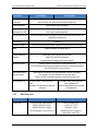
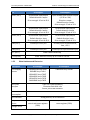
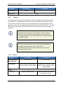
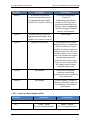
A Guide to Transitioning from the Grasshopper to the Grasshopper2 FireWire Camera Technical Application Note TAN2011001 Revised May 24, 2012 1.1 Subject Technical Application Note (TAN2011001): A Guide to Transitioning from the Grasshopper to the Grasshopper2 FireWire Camera 1.2 Applicable Product(s) GRAS (all models) GS2-FW 1.3 Application Note Description The fully redesigned Grasshopper2 FireWire camera is the next generation version of the high performance Grasshopper. Housed in the same form factor as the Grasshopper, the Grasshopper2 offers several new features, including improved frame rates, optimized imaging performance and extended shutter Format_7 modes, enhanced opto-isolated GPIO, and conformance to version 1.32 of the Instrumentation & Industrial Digital Camera (IIDC) specification. The purpose of this Technical Application Note is to: 1. Outline the primary similarities and differences between the two cameras; and 2. Offer suggestions and pointers to end users for migrating their custom applications from the Grasshopper to the Grasshopper2. For customers upgrading from a Grasshopper camera, Point Grey strongly encourages putting the Grasshopper2 through a full requalification process. PGR, the Point Grey Research, Inc. logo, FlyCapture, Digiclops, Dragonfly, Dragonfly Express, Chameleon, Firefly, Flea, Ladybug, Zebra, Scorpion and Triclops are trademarks or registered trademarks of Point Grey Research, Inc. in Canada and other countries. Copyright © 2011-2012 Point Grey Research, Inc. All rights reserved. Point Grey Research TAN2011001 Guide to Transitioning from GRAS to GS2-FW For users migrating from the Grasshopper to the Grasshopper2 Gigabit Ethernet camera, see Knowledge Base Article 350. 1.4 General Considerations 1.4.1 Other Reference Documentation Other useful sources of information regarding specific features of the Applicable Product(s) include: Grasshopper Getting Started Manual Grasshopper2 Getting Started Manual (forthcoming) Grasshopper and Grasshopper2 GS2-FW Technical Reference Manuals 1.4.2 Testing Tools To configure and test the information presented in this TAN: 1. Connect the camera’s GPIO pins to an oscilloscope or external trigger source. By connecting the appropriate GPIO pins to an external trigger source or oscilloscope, you can observe the differences in general purpose input/output capability of the Applicable Product(s). Consult your camera’s Technical Reference or Getting Started manual for: a. GPIO connector pin layouts; and b. GPIO electrical characteristics 2. Download the FlyCapture SDK. The SDK includes numerous example programs that demonstrate various camera features. Specific examples that relate to this TAN include CustomImageEx, AsyncTriggerEx and SaveImageToFlashEx. 3. Access the camera’s register space. The easiest way to try this is using the FlyCap demo software included with the FlyCapture SDK. For register definitions and individual bit descriptions, please refer to the Point Grey Digital Camera Register Reference or your camera’s Technical Reference manual. 1.5 Mechanics The Grasshopper and Grasshopper2 share the same form factor and general mechanical properties. Revised 24-May-12 Copyright © 2011-2012 Point Grey Research, Inc. All rights reserved. 2 Point Grey Research TAN2011001 Description IR cut filter properties Guide to Transitioning from GRAS to GS2-FW Grasshopper Grasshopper2 The infrared cut-off filter used with color versions of the cameras is the same and has the same transmittance properties. GPIO connector Hirose HR25 8 pin connector CCD sensor placement on PCB The chip and lens holder mounting holes are centered relative to the four corner mounting holes. Overall dimensions Industry standard 44mm x 29mm x 58mm (excluding lens holder and 1394/GPIO connector) Lens holder Case description C-mount Black zinc (casted) with black aluminum top and Point Grey logo Mass 104g (excluding including optics) Tripod mounting bracket Secured by four (4) M2x2mm screws Meets ISO and ASA standards Included free of charge with every camera Mounting holes Three (3) M3x2.5mm holes on the bottom face Four (4) M2x2mm holes on the bottom face (for mounting bracket) Two (2) M2 holes on the top face Removable glass / IR filter system Development kit 1.5.1 BW models: protective dust glass between sensor and optics COL models: IR filter between sensor and optics Glass / IR filter screwed into place to allow easy removal Includes cable, 1394 interface card, software CD and Getting Started Manual. Includes cable, 1394 interface card, software CD. Getting Started Manual available for download. GPIO Properties Pin GPIO0 (Pin 1) Revised 24-May-12 Grasshopper Grasshopper2 Bi-directional input/output Default direction: input Default function: trigger Drive strength: 10 mA at 30 V Opto-isolated input (+3.3 V to +30 V) Direction: input Default function: trigger in Input delay time: 4 μs Copyright © 2011-2012 Point Grey Research, Inc. All rights reserved. 3 Point Grey Research TAN2011001 Pin Guide to Transitioning from GRAS to GS2-FW Grasshopper Grasshopper2 GPIO1 (Pin 2) Bi-directional input/output Default direction: output Drive strength: 10 mA at 30 V Opto-isolated open collector output (+3.3V to +30V) Direction: output Default function: strobe Drive strength: 25 mA at 30 V GPIO2 (Pin 3) Bi-directional input/output Default direction: output Drive strength: 10 mA at 30 V Bi-directional input/output Default direction: output Drive strength: 25 mA at 30 V GPIO3 (Pin 4) Bi-directional input/output Default direction: input Drive strength: 10 mA at 30 V Bi-directional input/output Default direction: input Drive strength: 25 mA at 30 V GND (Pin 5) Ground pin for all pins Ground pin for bi-directional IO, Vext, +3.3 V GND (Pin 6) Ground pin for all pins Ground pin for opto-isolated IO pins VEXT (Pin 7) +3.3V (Pin 8) 1.5.2 Power camera externally Power external circuitry up to a total of 150 mA. Other Hardware and Electronics Description Grasshopper Grasshopper2 CCD imaging sensors 640x480 Kodak KAI-0340 648x488 Sony ICX414 1384x1032 Sony ICX267 1384x1036 Sony ICX285 1624x1224 Sony ICX274 2448x2048 Sony ICX625 1384x1036 Sony ICX285 IEEE-1394 interface 9-pin IEEE-1394b (800Mb/s) Connector flush with case Secure jack screw connector Power consumption Less than 2.5 W A/D converter Analog Devices, 14-bit resolution Temperature Sensor Voltage Sensor Revised 24-May-12 On-board; accessible via control and status registers (CSRs) On-board; accessible via control and status registers (CSRs) Copyright © 2011-2012 Point Grey Research, Inc. All rights reserved. 4 Point Grey Research TAN2011001 Description Guide to Transitioning from GRAS to GS2-FW Grasshopper Current Sensor None LED Behavior 1.5.3 Grasshopper2 Same Firmware This section does not address the significant number of firmware enhancements that have been added in the Grasshopper2, but focuses on functional differences between the two cameras that could affect integration of the Grasshopper2 in existing Grasshopper-based applications. Users are encouraged to download the documents listed in Section 1.4.1: Other Reference Documentation for assistance with terms, camera specifications, and register definitions. Many default startup (power-up) parameters, such as resolution, frame rate, gain, and shutter, have changed in the Grasshopper2. The memory channels on the Grasshopper2 can be used for creating new default settings. Point Grey cannot predict if or how all of the following differences may affect user applications. This section provides recommendations on how to address some of the most obvious differences in functionality. 1.5.3.1 Format_7 Description Max Frame Rate at Max Resolution Pixel Formats Grasshopper Grasshopper2 15 FPS (ICX285) 30 FPS (ICX285) Mono8, Mono16, Raw8, Raw16, YUV411, YUV422, YUV444, RGB8 Mono8, Mono12, Mono16, Raw8, Raw12, Raw16, YUV411, YUV422, YUV444, RGB8 Region of interest only Region of interest only; yields fastest frame rates Modes Mode_0 Revised 24-May-12 Copyright © 2011-2012 Point Grey Research, Inc. All rights reserved. 5 Point Grey Research TAN2011001 Description Guide to Transitioning from GRAS to GS2-FW Grasshopper Grasshopper2 Mode_1 2X vertical binning and 2X horizontal subsampling; values are aggregated and averaged; limited or no increase in intensity 2X vertical binning and 2X horizontal subsampling (monochrome models) or 2X vertical and 2x horizontal subsampling (color models); values are aggregated without averaging; increased intensity, improved SNR. Mode_2 2X vertical binning; values are aggregated and averaged, with limited or no increase in intensity Not available Mode_3 Region of interest only 2X horizontal and 2X vertical additive binning, in monochrome pixel formats only. CCD gain amplifier is disabled, resulting in reduced dark current. ROI is not available. Mode_3 uses a slower pixel clock and does not support overlapping exposure with readout of the previous image. Frame rates are compromised in this mode in favor of higher extended shutter times. Mode_4 Not available 2X vertical binning and 2X horizontal subsampling; increased frame rate; available on color models only Mode_8 Not available Similar to Mode_3, except no binning is performed. Images can be outputted in all supported pixel formats. 1.5.3.2 Control and Status Registers (CSRs) Description Grasshopper Grasshopper2 1A40h – 1A44h Point Grey implementation 80000h – 80048h IIDC v1.32 implementation Redefined Registers LUT Revised 24-May-12 Copyright © 2011-2012 Point Grey Research, Inc. All rights reserved. 6 Point Grey Research TAN2011001 Guide to Transitioning from GRAS to GS2-FW Description Grasshopper Grasshopper2 XMIT_FAILURE 12FCh No presence bit Presence bit FRAME_INFO 12F8h No inquiry bits for each embedded information type Inquiry bits for each information type Controlled using IMAGE_DATA_FORMAT 1048h DATA_DEPTH 630h IIDC v1.32 implementation New Registers Y16 Endianness Mirror Image Y8 or Y16 Grayscale or Raw Bayer Output MIRROR_IMAGE_CTRL 1054h BAYER_MONO_CTRL 1050h Current Sensor Access None CURRENT 1A58h – 1A5Ch Description Grasshopper Grasshopper2 IIDC Version 1.31 1.32 Color models output greyscale information when run in standard (Format_0 or Format_1) Y8/Y16 modes. The conversion from raw Bayer information to greyscale is done on-board the camera. On color models, conversion from raw Bayer information to greyscale is done on-board the camera. Lookup Table 11-bit to 9-bit mapping Three (3) LUT’s for RGB 9-bit to 9-bit mapping Two (2) banks, each containing three (3) channels for RGB Trigger Modes IIDC modes 0, 1, 3, 14, 15: Supported on all models IIDC modes 4, 5: Supported on 03S2 and 08S2 only IIDC modes 0, 1, 3, 4, 5, 14, 15 > 10 s Up to 330 s (Format_7 Mode_3 and Format_7 Mode_8) 1.5.3.3 Other Firmware Changes Color processing Extended Shutter Times Revised 24-May-12 Copyright © 2011-2012 Point Grey Research, Inc. All rights reserved. 7 Point Grey Research TAN2011001 Description Guide to Transitioning from GRAS to GS2-FW Grasshopper Memory Channels Grasshopper2 Two (2) channels for user-defined configuration sets; one (1) channel for restoring to factory default settings Frame Buffer 32 MB for temporary image storage and re-transmission Non-Volatile Flash Memory Pixel Clocks 512 KB for data storage Two (2) or more settings; may change with format/mode change Max two (2) settings; will change only when setting to Format_7 Mode_3 or Format_7 Mode_8. Grasshopper Grasshopper2 FlyCapture 2.x Applications Supported Supported FlyCapture 1.x Applications Supported FlyCap Demo GUI does not support new IIDC 1.32 video formats and other new features. New features are supported in the API. 1.5.4 Software Support Description Revised 24-May-12 Copyright © 2011-2012 Point Grey Research, Inc. All rights reserved. 8 Point Grey Research TAN2011001 Guide to Transitioning from GRAS to GS2-FW 1.6 Additional Downloads and Support Point Grey Research Inc. endeavors to provide the highest level of technical support possible to our customers. Most support resources can be accessed through the Support section of our website. Creating a Customer Login Account The first step in accessing our technical support resources is to obtain a Customer Login Account. This requires a valid name and email address. To apply for a Customer Login Account go to the Downloads page. Knowledge Base Our Knowledge Base contains answers to some of the most common support questions. It is constantly updated, expanded, and refined to ensure that our customers have access to the latest information. Product Downloads Customers with a Customer Login Account can access the latest software and firmware for their cameras from our Downloads page. We encourage our customers to keep their software and firmware up-to-date by downloading and installing the latest versions. Contacting Technical Support Before contacting Technical Support, have you: 1. Read the product documentation and user manual? 2. Searched the Knowledge Base? 3. Downloaded and installed the latest version of software and/or firmware? If you have done all the above and still can’t find an answer to your question, contact our Technical Support team. Revised 24-May-12 Copyright © 2011-2012 Point Grey Research, Inc. All rights reserved. 9