1
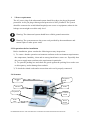
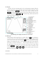
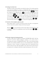
EICKEMEYER MAGIC 2000 Veterinary Ultrasound System Operating Manual MEDIZINTECHNIK FÜR TIERÄRZTE Eltastraße 8 D-78532 Tuttlingen Telefon 0 74 61 / 9 65 80-0 Telefax 0 74 61 / 9 65 80 90 e-mail: [email protected] Internet: http://www.eickemeyer.de EICKEMEYER MAGIC 2000 ULTRASOUND SCANNER OPERATING MANUAL Dear Doctor, Thank you very much for choosing the EICKEMEYER MAGIC 2000 Veterinary Ultrasound System! It’s a high quality portable with a wide range of applications and many of unique functions. To ensure the system can be operated safely, correctly and properly to deliver its best performance, please kindly read and understand this user manual before you start to install or operate it, and please strictly follow all the instructions when you install and operate it. Besides, please also kindly remember to review this operation manual regularly, as it will be a good tool to help you maximize your work efficiency and effectiveness. To maintain our excellent service and for warranty purposes it is necessary to register your system. Please us the web www.eickemeyer.de/Magic2000.html . This will ensure that you are covered by our international warranty. Should you have any question, please always feel free to contact us. With our best regards EICKEMEYER Medizintechnik für Tierärzte Alexander Sprung General Manager EICKEMEYER MAGIC 2000 VETERINARY ULTRASOUND SYSTEM OPERATING MANUAL 1 INDEX Section Page Introduction ……………………………………………………………………………1 Index …………………………………………………………………………………..2 1. General description ………………………………………………………………....4 1.1 Purpose of use................................……….........................……………………..4 1.2 Features .............................................................................……………….……..4 1.3 Main functions....................................................................……………………..5 1.4 Major technical specifications...........................................……….……………..6 1.5 Operating conditions...........................................................……………………..7 1.6 Security type…………………………………………………………………….7 1.7 Packing list......................................................................………………………..7 1.8 Optional extras…………………………………………………………………..8 1.9 The meaning of mark notes……………………………………………………..9 2. Installation .......................................................................………………….………10 2.1 Conditions………………………………………………………………………10 2.2 Power requirement………………………………………………………………11 2.3 Preparations……………………………………………………………………..11 2.4 Structure…………………………………………………………………………11 2.5 Dimension……………………………………………………………………….12 2.6 Rear panel……………………………………………………………………….12 2.7 Control panel………………………………………………………………….…12 2.8 Installation……………………………………………………………………… 13 3. Operation….......................................................................…………………………..15 3.1 Power switch…………………………………………………………………….15 3.2 Selection of probe type…………………………………………………………..15 3.3 Mode selection......................................................….....………………………...16 3.3.1 B mode………………………………………………………………….…16 3.3.2 B/B mode……………………………………………………………….…16 3.3.3 M mode……………………………………………………………………17 3.3.4 B/M mode…………………………………………………………………17 3.4 Definition of image…………………………………………………….……….17 3.4.1 Contrast and brightness of image…………………………………………17 3.4.2 Gain control……………………………………………………………….18 3.4.3 Four frequencies…………………………………………………………..19 3.4.4 Linear averaging…………………………………………………………..19 3.4.5 Frame averaging…………………………………………………………..19 3.4.6 Image processing………………………………………………….………19 3.5 Zooming and depth change…......................….................................……… 20 3.5.1 Zooming…………………………………………………………………..20 3.5.2 Depth change………………………………………………………….….20 EICKEMEYER MAGIC 2000 VETERINARY ULTRASOUND SYSTEM OPERATING MANUAL 2 3.6 Image control…………………………………………………………….……..20 3.6.1 Image freezing…………………………………………………….……...20 3.6.2 Selection of scanning direction…………………………………………..20 3.6.3 Image black/white ,up/down reversing…………………………………..20 3.6.4 Focus selection…………………………………………………….……..20 3.7 Image storage and recovery…………………………………………………….21 3.8 Measurement and calculation………………………………………………..…21 3.8.1 Measurement and calculation in B-, B/B-mode operating states….……..21 Distance measurement………………………………………………..22 Measurement of circumference and area (tracing method)……………22 Measurement of circumference and area (elliptical method)………….23 Volume measurement (three-axis method)…………………………….24 3.8.2 Measurement and calculation in B/M-, M-mode operating states………..25 Distance measurement…………………………………………………25 Measurement of heart rate……………………………………………..25 3.9 Reproduction measurement for animal gestation age and EDD…………………26 3.9.1 Measure bovine gestation age and EDD…………………….……….……27 3.9.2 Measure Equine gestation age ……………………………………………27 3.9.3 Measure Ovine gestation age……………..………………………………28 3.9.4 Measure canine gestation age and EDD……………………………..……29 3.9.5 Measure feline gestation age………………………………………...……29 3.10 Name of hospital and ID comment……….……………………………………30 3.10.1 Entry of characters for comment…… …………………………………..30 Entry of name of hospital………………………………………………30 ID indication ………………………………………………….……….31 Comment in image area…………………………………………….….31 3.10.2 Body mark selection and probe mark turnover……………………….….31 3.11 Record………………………………………………………………….………32 3.12 Setting of real-time clock………………………………………………….……32 3.13 Selection of beam sampling/puncture guide……………………………………32 3.14 Function of green environment protection……………………………………..33 3.15 Usage of cine-memory card (optional)…………………………………………33 4. Maintenance………………………………………………………………………….38 4.1 Main unit…………………………………………………………………..……..38 4.2 Probe……………………………………………………………………………..38 4.3 Maintenance……………………………………………………………….……..39 4.4 Replacement of fuse……………………………………………………………..39 4.5 EMC electromagnetic compatibility…………………………………………….40 4.6 Requirement of environmental protection………………………………….……40 4.7 Precision measurement………………………………………………………….40 5. Warranty.............................................................................…………………………..41 6. Troubleshooting………………………………………………………………………42 EICKEMEYER MAGIC 2000 VETERINARY ULTRASOUND SYSTEM OPERATING MANUAL 3 Chapter 1 General Description 1.1 Purpose of use The EICKEMEYER MAGIC 2000 is an advanced and high quality Veterinary ultrasound diganostic system developed by adopting the most up-to-date technologies of sound, bio-medical engineering & electronics. It is a linear- and convex-array electronic scanning system. Different probes are available: 5.0MHz linear array rectal probe (multifrequency) Art. No. 303894 5.0MHz R20 micro-convex probe (multifrequency). Art.No. 303896 other probes are available upon request. The system can be used for examination and diagnosis of small aninmals and large aniamlsl in abdominal, reproduction, small parts, urology, cardiology , tendons etc. Before operating this ultrasound system, please make sure the operator has read this operation manual carefully and can thus operate system correctly to make it work according to its specified safety standard and reach its performance standard. 1.2 Features 1.2.1 It has 4-step multi-frequency conversion function for all the probes, to allow the erinarian to tailor the frequency to different animal body size. It also have 8 STC curves and 4 image processings (IPs) available for choice. 1.2.2 The images displayed by the system are crystal clear, stable and with high resolution due to adopting the latest techniques, such as continuously variable aperture, automatic multi-stage focussing, TGC, dynamic filtering, image edge enhancement, frame correlation, linear interpolation, 256 gray scales image display, wide dynamic range and wide-band low noise preamplifiers, logarithmic compression etc. 1.2.3 It has very abundant display and measurement features including image freezing function, measurements of distance, circumference, area, volume (normal, bladder volume, thyroid volume) etc. It also has multi-mode display, zooming function with depth change, image reversions functions for the image processing. It provides up to 5 kinds of animal reproduction software, covering bovine, ovine, equine, canine and EICKEMEYER MAGIC 2000 VETERINARY ULTRASOUND SYSTEM OPERATING MANUAL 4 feline. And Veterinarians’ comment, animal name and real-time clock setting can be displayed in image area. By using a track ball, various measurements can be performed conveniently and flexibly. 1.2.4 Moreover, by adopting special high-integration devices and high-speed CMOS ICs, the EICKEMEYER MAGIC 2000 delivers more useful features with much better reliability than a tradition ultrasound scanner but at a lower power consumption. 1.2.5 The design of all-plastic case covered with plastic diaphragm, large monitor with fold-up keyboard gives it a beautiful and modern outlook. 1.2.6 The unit is equiped with a large 10 inch high resolution rectangular black-white SVGA monitor , which provide flashing-free high quality images by adopting the unique continuous line-to-line scanning method. With large and stable images, operators will not easily feel eye-fatigue during long-time examination as they used to be when using a traditional system with only 7-inch PAL monitor. 1.3 Main functions 1.3.1 It supports the B, B/B, B/M-, M- mode image displays. At the time of M- or B/Mmode image display, four kinds of sweep speeds -- 2s, 4s, 6s, 8s-- are provided; 1.3.2 It provides 4-step image magnification at ×1.0,×1.2,×1.5,×2 with depth change; 1.3.3 It provides the adjustment of near field, far field, total gain, and brightness and contrast control. 1.3.4 It uses the latest techniques such as 4-stage transmitting focus, 4-stage dynamic receiving focus, dynamic aperture control, dynamic frequency scanning, etc; 1.3.5 It supports the multi-frequency conversion; STC quick selection and image post-processing. 1.3.6 Cine- memory card: to allow the permanent image storage of 8 frames Max., and the record & back-play of 64 frames Max. 1.3.7 It supports image freezing and various image storage functions. 1.3.8 It supports up/down, left/right and positive/negative image reversing functions; 1.3.9 It supports the measurements of distance, circumference, area, volume and fetal weight, as well as the automatic calculation and direct presentation function, including the fetal age and expected delivery date, heart rate etc. 1.3.10 Both the elliptical or tracing methods are available for the measurement of area. 1.3.11 It provides 16 kinds body marks together with the corresponding probe position indication. The full-screen annotation, animal name input are also available, and the date and time is provided by a real-time clock . EICKEMEYER MAGIC 2000 VETERINARY ULTRASOUND SYSTEM OPERATING MANUAL 5 1.3.12 The track ball are build-in the keyboard to allow easy and flexible measurement and operation; 1.3.13 Standard PAL-system video signal output and VGA signal output. 1. 4 Major technical specifications Available Veterinary probes: - 5.0MHz linear rectal probe, 80 elements, 4-step multi-frequency 3.5/5.0/6.0/7.0 MHz. (Art. No. 303894) - 5.0MHz micro-convex probe, Radius 20mm, 80elements, 4-step multi-frequency 3.5/5.0/6.0/7.0 MHz. (Art. No. 303896) Scanning depth: 150mm - 3.5 MHz R60 convex array probe, 80-elements, 4-step multi-frequency 2.5/3.5/4.0/5.0 Mhz (Art.No. 303898) Scanning depth: 220mm Monitor : The unit is equiped with a build-in 10 inch high resolution rectangular black-white SVGA monitor , which provide flashing-free high quality images by using the unique continuouse line-to-line scanning method. Gray scale : 256 Error of geometric position : Power supply < 5% : 230V AC ±10%, 50Hz ±1Hz, grounded Power consumption: Not greater than 100VA MTBF : Designed value is larger than 3000 hours. 1.5 Operating conditions Ambient temperature: 5 – 40 Celsius Relative humidity: 30 – 80% RH Atmospheric pressure: 86 – 106 KPa Power requirement: 230V AC ±10%, 50Hz±1Hz, grounded EICKEMEYER MAGIC 2000 VETERINARY ULTRASOUND SYSTEM OPERATING MANUAL 6 Because of the instability of the local electricity voltage at some areas, a power supply stablizer is recommended to be used to protect the system and to ensure the steady image display. The system should be placed in a well-ventilated dry environment and kept away from strong electromagnetic interference, poisonous and corrosive gas. Direct exposure to sunlight and rain should be avoided. 1.6 Security type - Anti - electrical shock type: Class I equipment. This means the equipment not only has the basic insulation, but also has the grounded to provide protection against the electrical shock. - Level of anti-shock: Type BF equipment. This means the equipment is the Type B equipment equipped with the Type F applied parts. - Type B equipment: This means the equipment can provide the protection against the electrical shock to certain level if the equipment is within the permissive current leakage limit. 1.7 Packing list Main unit 1 set Probe holder 1 pc Aluminum hand-carry case for probe 1 pc Power cord 1 pc Ultrasonic gel 1 bottle Operating manual 1 copy QC Pass 1 copy 1.8 Optional parts available 1) 5.0MHz linear rectal probe, 80 elements, 4-step multi-frequency 3.5/5.0/6.0/7.0 MHz. (Art. No. 303894) max .scanning depth: 150mm EICKEMEYER MAGIC 2000 VETERINARY ULTRASOUND SYSTEM OPERATING MANUAL 7 2) 5.0MHz micro-convex probe, Radius 20mm, 80elements, 4-step multi-frequency 3.5/5.0/6.0/7.0 MHz. (Art. No. 303896), max .scanning depth: 150mm 3) 3.5 MHz R60 convex array probe, 80-elements, 4-step multi-frequency 2.5/3.5/4.0/5.0 Mhz (Art.No. 303898), max .scanning depth: 220 mm 5) Archiving: Video printer or DVD Recorder 6) 14-inch SVGA monitor: can be connected directly to the main unit to display larger images at the same time. Caution: Please choose the printers acknowledged by the manufacturer; otherwise it may cause damage to the system. Please refer to the operation manual of the printer for the installation and operation details. EICKEMEYER MAGIC 2000 VETERINARY ULTRASOUND SYSTEM OPERATING MANUAL 8 1.9 The Meaning of Mark Note Note Caution Please read the operating manual Warning High-voltage Protective earth terminal Security type Signal grounded Potential equalization conductor terminal Signal output Brightness of monitor Contrast of monitor Main unit power off Main unit power on EICKEMEYER MAGIC 2000 VETERINARY ULTRASOUND SYSTEM OPERATING MANUAL 9 Chapter 2 Installation 2.1 Installation conditions The ultrasound system should be working in an environment without strong magnetic-field interference, and free of strong electric interference from the electricity network. The room should be well ventilated, clean, dark and have stable temperature (within the limits set below) ,and without poisonous, corrosive and inflammable gas. The ultrasound system should be operated, preserved and transported under the following conditions: Conditions Operation Preservation Transportation Temperature 5C—40C -5C—40C -30C—55C Humidity 30%--80% no condensation less than 80% no condensation less than 95% no condensation Atmospheric pressure 86kPa— 106kPa 86kPa— 106kPa 50kPa— 106kPa Parameters Caution: When moved from outside, the ultrasound system might be still too cold and too warm compare to the room temperature. Because of the temperature difference, water may condense inside the machine. So before turning on the power, the system should be put inside the room for a while to get adapt to the environment. If the room temperature is beyond the above temperature range, then adapting time need to be prolonged for 1 hour for each additional temperature difference of 2.5C Note: The ultrasound system should be used far away from the electritity generator, X-ray machine, broadcasting station, TV station, computer and transmission cable, to avoid interference to the image. A working room with air conditioner is prefered. EICKEMEYER MAGIC 2000 VETERINARY ULTRASOUND SYSTEM OPERATING MANUAL 10 1 2 Power requirement The AC power plug of the ultrasound system should be a three-pin plug with ground protection. A two-pin plug without ground protection is NOT permitted. The system should be connected to an individual hospital power source or equipment, otherwise the leakage current might exceed the safty level. Warning: The ultrasound system should have reliable ground connection. Warning: The system must use the power cord provided by the manufacturer and cannot replace it other power cords. 2.3 Preparations before installation Before installation, please conduct the following necessary inspections: 1) To ensure that the operation environment conforms to the environment requirements: the temperature, humidity, clean and no strong interference source etc. Especially that the power supply must conform to the requirement in particular. 2) To open the packing box and check the goods against the packing list to make sure no discrepancy, and no damage from outlook. 3) To check the related cords and to ensure that each cord is properly connected. 2.4 Structure Ultrasonic gel Monitor Keyboard Track Ball Brightness Knob Probe Contrast Knob Power Switch EICKEMEYER MAGIC 2000 VETERINARY ULTRASOUND SYSTEM OPERATING MANUAL 11 Fig. 1 The Outlook of the Main Unit 2.5 The dimension of out frame: Main unit: 450×280×300 mm 2.6 The rear panel of the main unit Fig 2 Diagram of rear panel of the main unit EICKEMEYER MAGIC 2000 VETERINARY ULTRASOUND SYSTEM OPERATING MANUAL 12 2.7 Control panel (Keyboard) Fig 3 Diagram of control panel 1. Alphanumeric keys 2. Control key 3. Menu key 4. Annotation key 5. Patient ID number key 6. Gynecological data table selection key 7. Body marks key 8. Frequency steps selection key 9. Image processing selecting key 10. Measuring key 11. Storage control key 12. Set key 13. Track ball 14. End key 15. Focus points selection key 16. Depth control key 17. White/black, Left/Right image reversing key 18. FREEZE key 19. Zooming key 20. B mode switching key 21. B/B mode switching key 22. B/M mode switching key 23. M mode switching key 24. Total gain selecting key 25. CAPSLOCK key 26. SHIFT key 27. Far gain selecting key 28. Near gain selecting key 29. Clear key 30. Power indicator light EICKEMEYER MAGIC 2000 VETERINARY ULTRASOUND SYSTEM OPERATING MANUAL 13 2.8 Installation a. Open the packing box, take out the main unit and place it steadily on a table. b. Connect the plug of probe cord to the probe socket (also called probe connector) at the rear of the main unit and tighten the probe handle. (The probe cord has an easy-to-connect plug. When fitting the probe, first please check the small protuberant lock pin inside the plug and the corresponding slot inside the socket, make sure that the lock pin is in the same direction as the slot, otherwise please turn the handle key on the plug until the pin and the slot are in the same direction. Then slightly insert the plug into the socket, the lock pin will into the slot, and then clockwise turn the handle key on the plug to the “Tight” position. When removing the probe, firstly turn the handle key anti-clockwise to the “Loose” position and slightly take the plug out of the socket. Don‘t push in or pull out the plug by strength. Handle key c. After ensuring that the AC power provided meets the power supply requirements of the system(please refer to Section 1.5 of this user manual) , please connect one terminal of the power cord to the power inlet socket at the rear panel of the main unit, and plug the other terminal to the AC power socket of the hospital. d. After turning on the power switch, the system enters into the normal operating state. Caution: Before connecting the plug to the hospital AC power socket, please make sure that the voltage of power supply is AC 230V, and the power switch of the main unit is turned off. The probe must be connected or disconnected only when the system is powered off. The VGA OUT socket on the rear panel of the main unit is used for connection to the external SVGA monitor . Please refer to the SVGA operation manual for the details of its installation and operation. EICKEMEYER MAGIC 2000 VETERINARY ULTRASOUND SYSTEM OPERATING MANUAL 14 Chapter 3 Operation 3.1 Power switch After making sure that the system is connected to the proper external AC power supply, please turn on the power switch of the system. The power switch is located at the lower right part of the monitor. When pushing it to the “On” or “I” side, the system is powered on and will start working and the power indicator on the keyboard will be lit. It will be contrary when the switch is pressed to the “Off” or “O” side. Note: To ensure a long-time stable and reliable operation, the system can’t be switched on immediately after being powered off. Please kindly wait for at least 1 minute before restarting it. Warning: Please do not place any liquid on or around the main unit. Once spilled, the liquid will reach the electrified parts of the system and increase the possibility of electricity shock. 3.2 Selection of probe types The EICKEMEYER MAGIC 2000 has a single probe connector (socket) as a standard configuration. The system can automatically recognize the probe once the probes are connected to the system. The name of the probe chosen will be displayed at the right bottom area of the screen. Warning: It is strictly prohibited to use any probe other than the probes provided by EICKEMEYER, otherwise the system and probe may be damaged. The manufacturer will not be held responsible for any damage arising from such misapplication, and it’s also not covered by our warranty terms. Unplug the probe: Please switch off the power of the main unit before connecting and removing the probe(s). 3.3 Mode selection The EICKEMEYER MAGIC 2000 has four scanning modes—B, B/B, B/M and M. Scanning modes can be changed only during the real-time image display. A description of all the scanning modes for this convex array probe is given below. EICKEMEYER MAGIC 2000 VETERINARY ULTRASOUND SYSTEM OPERATING MANUAL 15 3.3.1 B mode B mode is the basic operating mode for the two-dimensional scanning. When the system is powered on, it will automatically enter into the B-mode freezing state. At that time, by pressing the FREEZE key, the probe starts real-time scanning. Press the FREEZE key again and the image displayed will be frozen. When the system is in the real-time state, press the B/B or B/M or M mode function key, and the system will exit from B mode to the pressed mode. Fig.4 Meaning of the display and characters on the screen 3.3.2 B/B mode In the B/B mode, double-image display is available. When the B/B mode switching key is pressed, choice can be made between the live and frozen images displayed on the screen. In the real-time state, when pressing the B/B mode key, the right and left image displays will exchange their status, i.e. the original live image will be frozen while the other image is activated. At that time, a mark will appear under the two arrows at the right portion of the screen and it will point at the current active image. When pressing FREEZE key again, the current image will be frozen or defrozen. In the real-time state, press the B or B/M or M mode key and the system will exit the B/B mode to the pressed mode. 3.3.3 M mode EICKEMEYER MAGIC 2000 VETERINARY ULTRASOUND SYSTEM OPERATING MANUAL 16 The M mode image reflects the movement of all the points on the sampling line of the targeted examination area. The M-mode image display will vary with time, so it is suitable for the cardic examination. In the real-time state of B or B/M mode, when pressing the H key, a vertical dotted line (i.e. sampling line) will appear. The line can be moved to the targeted position during M-mode by pressing the and the fast moving keys. When the M key is pressed, M-mode image is displayed. The current sweeping speed can be selected with the M key, there’re 4-step of sweeping speeds available for choice, 2s,4s,6s,8s. When the system is in the real-time state, press any mode key except the M key, the M -mode image display will be ceased. 3.3.4 B/M mode In the B/M mode, both B-mode and M-mode image displays can be provided simultaneously. By placing the beam sampling line at position of the heart beating area in the B-mode image region, a corresponding M-mode image will be presented in the M-mode image region. In the real-time state, by pressing the B/M key, the B/M mode image display can be obtained. The B/M key can be used to select sweep speed. The system has four sweep speeds--2s, 4s, 6s, 8s available for selection. The selected sweep speed is shown below the scanning direction arrow at the right portion of the screen. For example, TM=2s. By pressing the FREEZE key, the displayed image is frozen. When the system is in the real-time state, press any mode key except the B/M key, it will exist from the B/M mode 3.4 Definition of image 3.4.1 Contrast and brightness of image The contrast and brightness of monitor is one of important factors which will determine the image quality. The operator should make the adjustment of the contrast and brightness according to its actual surrounding environment. Contrast control The black-and-white contrast of can be adjusted by turning the knob below the mark at the right part of monitor, the contrast will get stronger by clockwise turning EICKEMEYER MAGIC 2000 VETERINARY ULTRASOUND SYSTEM OPERATING MANUAL 17 the knob or vice versa. Normally sharp contrast will enhance the edge of image, and lower contrast will be good for the analysis of the targeted object’s nature, as it enhances the gradation of the image. Operator should make the appropriate adjustment according to requirement of diagnosis. Brightness control The brightness can be adjusted with the knob below the ☼ mark at the right part of monitor. It will be brightened by clockwise turning the knob or vice versa. Brightness should be adjusted in association with the contrast, the contrast will decrease if the brightness is set too high, while the gradation will decrease if the brightness is set too low. Please appropriately adjust the contrast in association with brightness according to actual need and the working environment. Suggestion Normally, it’s suggested to set the contrast and brightness to the extent that the lower gray scale area at the lower left portion of screen is well displayed. In that setting, a clear image with good gradation will be displayed. 3.4.2 Gain control Total gain: Two , touch keys of GAIN are provided for adjusting overall ultrasonic echo receiving sensitivity to obtain a satisfactory image display. Its adjusting range is 0 99. Near gain: Two , touch keys of NEAR are provided for adjusting near-field receiving sensitivity of ultrasonic echoes to obtain an optimum near-field image display. Its adjusting range is - 30 0. Far gain: Two , touch keys of FAR are provided for adjusting far-field receiving sensitivity of ultrasonic echoes to obtain a clear far-field image display. Its range is 0 30. The system offers eight STC curves for user to select. During real-time B-mode image display press the SHIFT and the eight STC curves are displayed in turn in the middle of character area at the right portion of the screen. When the END key is pressed, the system will exit from selection of STC curve. 3.4.3 Four frequencies Each probe is capable of scanning at four different frequencies. Low frequencies are suitable for fatter patients and high frequencies for thinner patients. The frequencies can EICKEMEYER MAGIC 2000 VETERINARY ULTRASOUND SYSTEM OPERATING MANUAL 18 be changed over by using the FREQ key. Real-time scanning frequency is shown in the FR: area at the lower right portion of the screen. 3.4.4 Linear averaging Linear averaging is to control smoothness of image and decrease image noise by taking percentage of previous and present picture-elements (pixel) at the same specified beam. Linear averaging is merely applied in B- or B/B-mode operation. The percentage indicated in the LC: area at the lower right portion of the screen is the related value of the previous pixel chosen and the current pixel. Linear average can be changed over by pressing the SET key in real-time state. Linear average 0% or 25% is recommended for use. 3.4.5 Frame averaging Frame averaging is to control smoothness of image by taking percentage of previous and present frame images specified at the screen. It can also be used for decreasing noise and light stains. It is merely applied during B- or B/B-mode image display. The percentage indicated in the FC: area at the lower right portion of the screen is the related value of the previous frame image and the current image. Frame average can be changed over by pressing the END key in real-time state. 3.4.6 Image processing Image processing is to select different gray scale curves to enhance or lessen some gray scales so as to get better image for the observation and analysis. The system has four gray scale curves. They can be selected and displayed in the IP: area at the lower right portion of the screen by pressing the IP key. IP: 3 represents selection of linear curves, which won’t intensify structure of image. IP: 2 represents intensification of brightness of image with high gray scale. The image becomes gentle and surrounding tissue is intensified. (Used for diagnosis of soft tissue) IP: 1 means that amplitude of intensifying brightness of image with high gray scale is further increased relative to curve 1 (Used for diagnosis of soft tissue). IP: 0 means that middle-bright gray scales are intensified to get a higher contrast. As a result a clearer image is obtained for diagnosis of structure with low echoes. EICKEMEYER MAGIC 2000 VETERINARY ULTRASOUND SYSTEM OPERATING MANUAL 19 3.5 Zooming and depth change 3.5.1 Zooming During real-time single B-mode image display, the / control is used for switching magnifications of ×1.0, ×1.2, ×1.5 and ×2.0 to obtain a definite image display and a best measurement result. 3.5.2 Depth of image During real-time image display, when an image of ×1.2, ×1.5 or ×2.0 magnification is taken, it is necessary to use the DEPTH key to vertically move an image on the screen to different depth accordingly. Depth of image is indicated by graduations at the right portion of the image with 1 cm each graduation. 3.6 Image control 3.6.1 Image freezing During real-time image display, by operating the FREEZE key, the displaying image can be turned into the frozen image. When pressing the FREEZE key again the original real-time image is reset. 3.6.2 Selection of scanning direction The NEG key is used for reversing scanning direction of probe during real-time image display. When the key is pressed, the displayed image is turned over in the right-left direction. The scanning direction arrow in the character area at the right portion of the screen is reversed at the same time. 3.6.3 Image reversing During frozen image display, by pressing the NEG key, the displayed image can be changed from negative to positive (black to white) for making slides for study. First press the CTRL key ,then press the NEG , the image will change from up to down. 3.6.4 Focus selection By properly adjusting focus a clear image can be displayed in a certain target area during real-time image display of any mode. EICKEMEYER MAGIC 2000 VETERINARY ULTRASOUND SYSTEM OPERATING MANUAL 20 The focus setting is shown behind F0 at the upper right portion of the screen. Focuses of Near field, Middle field, Far field 1 and Far field 2 are indicated as the corresponding digital codes: 1, 2, 3, 4. When a certain focus is taken, the corresponding digit code will be shown behind F0 at the upper right portion of the screen. When the selected focus is cancelled, the corresponding digit code will be blanked off. During B- or B/B-mode image display multi-stage focus can be selected. However, selection of too many focuses will cause the displayed image to flash. Normally three focuses are recommended for use. Operating procedure: In the two modes of image displays focus is selected by using the FOCUS control. The left key of FOCUS is used for selecting a single focus and the right one for changing combination of multiple focuses in turn. During the M-mode and B/M-mode image displays only a single focus can be selected. In the two modes of image displays focus can only be changed over in the sequence of 1, 2, 3, 4 with the FOCUS control. 3.7 Image storage and recovery 3.7.1 During B-mode image display one image can be stored for comparison later. After the image is stored, when power is off or a new image is stored, the old stored image will be cleared or correspondingly replaced by a new stored one. 3.7.2 Storing If there is an image worthy of storage, use the FREEZE key to freeze the image; Press the key to store the image; Press the FREEZE key and the normal image is recovered; Press the FREEZE key to freeze the image; Press the key to recall the stored image for comparison; Press the FREEZE key to recover scanning. EICKEMEYER MAGIC 2000 VETERINARY ULTRASOUND SYSTEM OPERATING MANUAL 21 3.8 Measurement and calculation The system is capable of measuring distance, circumference, area, heart rate, and volume during image freezing as well as automatic calculation and presentation of the measured result on the screen. Note: During measurement, the H key can be used to activate or stop the cursor fast-moving function. 3.8.1 Measurement and calculation in B-, B/B- mode operating states In case of B- or B/B- mode image display distance, circumference and area can be measured Distance measurement a. Obtain valuable image; b. Press the FREEZE key to freeze the image; c. Press the MEAS key to select distance measurement; d. Press the SET key and a corresponding small “+” mark appears in image area; e. Use the mark-moving keys , , , or track ball to move the mark to an initial measuring point; f. Press the SET key and then a mark is fixed at the initial point; g. By using the mark-moving keys or track ball the mark is moved and a rubber-band-like line appears between the moving cursor and the fixed mark; h. When the cursor is moved to a terminating point, press the SET key and a fixed mark appears at the point. At the same time, a measured result is presented nearby and the value will be shown at the right portion of the screen as well; i. By repeating steps e – h, multiple measurements can be made; j. Press the END key and then the system will exit from measuring state with records retained. Use the CLR key and the system will not only exit from measuring state, but also clear all the records; k. Use the FREEZE key to exit from the measuring state and return to real-time operating state with all the results erased; Measurement of circumference and area (tracing method) a. Obtain useful image; b. Press the FREEZE key to freeze the image; EICKEMEYER MAGIC 2000 VETERINARY ULTRASOUND SYSTEM OPERATING MANUAL 22 c. Press the MEAS key to select type of measurement; d. Press the SET key and then a corresponding small mark appears in the image area, “×” for circumference measurement and “: :” for area measurement; e. Use the mark-moving keys , , , or track ball to move the mark to an initial measuring point; f. Press the SET key and then a fixed mark appears at the initial point; g. By using the mark-moving keys or track ball the mark moves to form a trace on the screen; h. When the mark is moved to a terminating measuring point, press the SET key again and the dotted line between the initial point and the terminating point becomes a solid line, thus forming a desired and enveloped region. Meanwhile the spare lines outside the region are all automatically cleared and a contour line is remained. Finally, circumferential length or area of the region is automatically calculated and displayed at the right portion of the screen; i. By repeating step e – h multiple measurements of circumference can be made; j. When pressing the END key, the system will return to the original state with result record retained. Pressing the CLR key will bring the system back to the original operating state with all the result records erased. k. When using the FREEZE key the system will directly return to real-time image display with all the measured results cleared. time operating state with all the results erased; Measurement of circumference and area (elliptical method) a. Obtain useful image; b. Press the FREEZE key to freeze the image; c. Press the MEAS key and use the direction keys , or alphanumeric key 1 to select ELL. at the lower portion of the screen; d. Press the SET key and then a corresponding small mark appears in the image area; e. Use the mark-moving keys , , , or track ball to move the mark to an initial measuring point (an end of long axis of ellipse); f. Press the SET key and then a fixed mark appears at the initial point; g. By using the mark-moving keys or track ball the mark moves to draw an EICKEMEYER MAGIC 2000 VETERINARY ULTRASOUND SYSTEM OPERATING MANUAL 23 elliptical trace on the screen; h. When the mark is moved to a terminating measuring point (the other end of long axis of ellipse), length of the short axis of ellipse can be adjusted by using the N (increasing), M (decreasing) keys. After adjusting size of ellipse, press the SET key again and the area and circumference values of the ellipse are presented, thus fulfilling elliptical measurement; i. By repeating step d – h multiple measurements of circumference can be made; j. When pressing the END key, the system will return to the original state with result record retained. Pressing the CLR key will bring the system back to the original operating state with all the result records erased. k. When using the FREEZE key the system will directly return to real-time image display with all the measured results cleared. Volume measurement (three-axis method) a. Obtain useful image; b. Press the FREEZE key to freeze the image; c. Press the MENU key and use the direction keys , or alphanumeric key 2 to select VOL. at the lower portion of the screen; d Use the direction keys , to select desired volume formula. Press SET key to select it; e. Press SET key again and a corresponding small mark appears in image area; f. Use the direction keys , , , or track ball to move the cursor to measurement start point; g. Press the SET key to fix the start point; h. Press the direction keys , , , or turn the track ball to move the cursor to the measurement end point, there will be a dotted line between the start point and end point; i. Press the SET key to fix the end point. At the same time, the first distance value (diameter from top to bottom D1) will be displayed near the terminating point; j. By repeating step e – i, the second distance (diameter from front to back D2) is measured; k. Acquire the second image (cross section); l. Repeat steps e-i to measure the third distance (diameter from left to right D3). When the three distance values are obtained, the volume value appears EICKEMEYER MAGIC 2000 VETERINARY ULTRASOUND SYSTEM OPERATING MANUAL 24 immediately at the right portion of the image. Its unit is cm3. m. Repeat steps a-l to measure another volume value. Note: During distance measurement, press the END key to exit from distance-measuring status. Then press the END key again, the system will exit from the volume measurement states. Press CLR key and the system will exit from the measuring states and clear all the measurement records. There are three volume calculating formula available as follows: 1. NORMAL: Volume=(distance1* distance2* distance3*П)/ 0000 2. Bladder: Volume=(distance1* distance2* distance3*0.5233)/1000 3. Thyroid: Volume=(distance1* distance2* distance3*0.2083)/1000 3.8.2 Measurement and calculation in B/M-, M- mode operating states In B/M- and M- mode operating states distance and heart rate can be measured. Heart rate is expressed as number of heartbeats per minute. In order to ensure correct measurement the initial and terminating measuring points should have the same status in heart circulation, e.g. either at peak or in trough. Distance measurement See Measurement of distance in B-, B/B-mode operating states. Measurement of heart rate a. Obtain useful image; b. Press the FREEZE key to freeze the image; c. Press the MEAS key and measurement of heart rate is selected; d. Press the SET key and then a corresponding small mark appears in the image area; e. Use the mark-moving keys or track ball to move the mark to an initial point of a target to be measured; f. Press the SET key and then a fixed mark appears at the initial point; g. By using the mark-moving keys or track ball the mark moves to a point which is at the same status as the initial point with a heart circulation apart; h. Press the SET key and the mark is fixed at the terminating point. Thereby a heart rate is presented at the right portion of the screen. When the interval between the EICKEMEYER MAGIC 2000 VETERINARY ULTRASOUND SYSTEM OPERATING MANUAL 25 initial point and the terminating point is two heart cycles, the actual heart rate should be the indicated rate ×2 and on the analogy of this; i. By repeating step e – h multiple measurements of heart rate can be made; j. When pressing the END key, the system will return to the original state with the result record retained. Pressing the CLR key will bring the system back to the original operating state with all the result records erased. k. When using the FREEZE key the system will directly return to real-time image display with all the measured results cleared. 3.9 Reproduction measurement for animal gestation age and EDD The system can do reproduction measurement for bovine, equine, ovine, canine, and feline. Operating steps are as blow: Select B- or B/B-mode operating state; After scanning with probe, press the FREEZE key to freeze the displayed image; Press the key to open the animal menu to select desired animal species : BOV ………………… Bovine EQU ………………… Equine OVI ………………..…Ovine CAN ………………… Canine FEL ……………..…… Feline 3.9.1 Measure bovine gestation age and EDD The system can measure bovine BPD, CRL, TD, and automatically calculate bovine gestation age and EDD according to measurement result. Operating steps are as blow: After enter into animal menu, press the direction arrow key mark-moving keys , , , to move the cursor to “BOR”, then press SET key to select it; Press key to open the reproduction measurement function, and the measurement items will be displayed on the right side of the screen as below: BPD: ………………… BPD-(Name of measurement item) .. W.. D …………… W for week and D for day; EICKEMEYER MAGIC 2000 VETERINARY ULTRASOUND SYSTEM OPERATING MANUAL 26 EDD:…………………. Expected date of delivery ../.. …………………Month/ date Press OB key to select other measurement item in turn; Measure the item just as measuring distance or measuring area by Ellipse method. The result will be displayed at the right portion of the screen. Press CRL key to clear current measurement result, and can do new measurement; Press END key to quit. 3.9.2 Measure Equine gestation age The system can measure equine vesicle length, and automatically calculate equine gestation age. Operating steps are as blow: After enter into animal menu, press the direction arrow key mark-moving keys , , , to move the cursor to “EQU”, then press SET key to select it; Press key to open the reproduction measurement function, and the measurement items will be displayed on the right side of the screen as below: : ………………….… Length-(Name of measurement item) .. W.. D …………… W for week and D for day; Measure the Equine Length just as measuring distance. The result will be displayed at the right portion of the screen. When the measured length value is between 25mm to 26mm, the following note sentence will appear in the screen: “1) Within 18 to 26 days after pregnency. 2) Please find more details from user manual (Chapter 3) 3) Press the clr key to return to image.” More detail information is as follows: 17th-20th vesicle orientation 20th detection of embryo 24th detection of allantois 26th allantois 25% of vesicle 29th allantois 50% of vesicle EICKEMEYER MAGIC 2000 VETERINARY ULTRASOUND SYSTEM OPERATING MANUAL 27 Press CRL key to clear current measurement result, and can do new measurement; Press END key to quit. 3.9.3 Measure Ovine gestation age The system can measure ovine BPD, CRL, TD, and automatically calculate ovine gestation age and EDD according to measurement result. Operating steps are as blow: After enter into animal menu, press the direction arrow key mark-moving keys , , , to move the cursor to “OVI”, then press SET key to select it; Press key to open the reproduction measurement function, and the measurement items will be displayed on the right side of the screen as below: BPD: ………………… BPD-(Name of measurement item) .. W.. D …………… W for week and D for day; EDD:…………………. Expected date of delivery ../.. …………………Month/ date Press OB key to select other measurement item in turn; Measure the item just as measuring distance or measuring area by Ellipse method. The result will be displayed at the right portion of the screen. Press CRL key to clear current measurement result, and can do new measurement; Press END key to quit. 3.9.4 Measure canine gestation age and EDD The system can measure canine GS, CRL, HD, BD and automatically calculate canine gestation age and EDD according to measurement result. Operating steps are as blow: After enter into animal menu, press the direction arrow key mark-moving keys , , , to move the cursor to “CAN”, then press SET key to select it; Press key to open the reproduction measurement function, and the measurement items will be displayed on the right side of the screen as below: GS……………………..GS-(Name of measurement item) EICKEMEYER MAGIC 2000 VETERINARY ULTRASOUND SYSTEM OPERATING MANUAL 28 .. W.. D …………… W for week and D for day; EDD:…………………. Expected date of delivery ../.. …………………Month/ date Press OB key to select other measurement item in turn; Measure the item just as measuring distance or measuring area by Ellipse method. The result will be displayed at the right portion of the screen. Press CRL key to clear current measurement result, and can do new measurement; Press END key to quit. 3.9.5 Measure feline gestation age The system can measure feline HD, BD and automatically calculate feline gestation age and EDD according to measurement result. Operating steps are as blow: After enter into animal menu, press the direction arrow key mark-moving keys , , , to move the cursor to “FEL”, then press SET key to select it; Press key to open the reproduction measurement function, and the measurement items will be displayed on the right side of the screen as below: HD……………………..HD-(Name of measurement item) .. W.. D …………… W for week and D for day; EDD:…………………. Expected date of delivery ../.. …………………Month/ date Press OB key to select other measurement item in turn; Measure the item just as measuring distance or measuring area by Ellipse method. The result will be displayed at the right portion of the screen. Press CRL key to clear current measurement result, and can do new measurement; Press END key to quit. Note: For method of measuring elliptical circumference, refer to in 3.8.1. And the gestation age and EDD should be measured after the system quit from volume measurement stats.. EICKEMEYER MAGIC 2000 VETERINARY ULTRASOUND SYSTEM OPERATING MANUAL 29 3.10 Hospital Name and ID comment 3.10.1 Entry of hospital name and characters for comment The upper left part of the keyboard is mainly used for entering characters for comment. Small English letter and character at the upper part of key can be shifted by operating the ↑ key. In the state of mark alphanumeric key is written; in the state of the charater at the upper part of an the character at the lower part of the key is given. The CAPSLOCK key is used for shifting capital and small English letters, representing entry of capital letter and representing entry of small letter. In case a mistake is made in some character, press the BACKSPACE key the left character beside the cursor will be deleted. The CLR key is used for clearing the entire writing in this area. Entry of hospital name Characters HOSP at the upper portion of the screen: Following the characters is the display area of name of hospital. During frozen image display press the CTRL +S key and a “-”cursor is presented after HOSP:. At that time doctor can enter name of hospital. In hospital name area up to 26 characters can be written in. When name of hospital has been written in, press the END key to exit from the state of entry. After this, each time the system is started up, the entered name will be automatically displayed, unless it is altered. By pressing the CTRL +S key name of hospital can be rewritten. ID indication During frozen image display press the bV key and then the “-” cursor appears at the last row on the screen for operator to write in animal’s name and ID number. Each time a character is written above the flashing cursor, the cursor moves a step rightward. The cursor can move fast under the control of the cursor fast moving keys , or track ball. Up to 33 characters can be written in the ID area. Comment in image area During frozen image display press the key and the “-” cursor appears at the upper left portion of the screen. Use the moving keys or trackball to move the cursor to the position for comment. At that time characters or result can be written in the same way as ID entering. EICKEMEYER MAGIC 2000 VETERINARY ULTRASOUND SYSTEM OPERATING MANUAL 30 In the state of comment in image area the cursor can be moved in the entire image area. 3.10.2 Animal body mark selection and probe mark rotation At image frozen status, press body mark key key is pressed, a small graphic body mark to select animal body mark. When the appears at the right portion of the screen (character area) and indicates that the system enters into functioning states of body mark selection and probe mark rotation. At that time 16 body marks are shown for selection in the image area. At the upper left part of the image there is a → cursor. Use the body mark moving key or track ball to move the cursor → to a desired body mark. Then press the body mark key again to select it. At the same time the 16-body marks graph disappears and the selected body mark is displayed at the lower left portion of the screen. Here attention should be paid to the fact that when a body mark has been selected, the graphic body mark still exists at the right portion of the screen and indicates the position of probe. Meanwhile, a small arrow ← indicating probe position is shown in the body marks graph at the lower left portion of the screen. By operating the probe mark rotation key or track ball it is allowed to move to a corresponding position according to actual position of the probe. When the arrow is located at a desired position, it can be turned anti-clockwise by using the key; clockwise by the key to match with direction of probe. When pressing the key again the whole operation is finished. In case that there is no need for indicating position and direction of probe after selection of body mark, press the key to end the operation. 3.11 Record The standard configuration of the system doesn’t have the picture record. However the manufacture can supply upon customer needs (Sony UP-895MD printer, must conform to standard IEC60601-1) Please connect the video recorder to the video out socket on the rear panel of the main unit. Please read the user manual of picture record and connect the printer. When taking down the notes, please use the picture record according to its own user manual. Caution: All the video equipment that is connected to ultrasonic system must conform to standard IEC6060-1 and the grounded connector should be grounded on the external frame. EICKEMEYER MAGIC 2000 VETERINARY ULTRASOUND SYSTEM OPERATING MANUAL 31 3.12 Setting of real-time clock The built-in real-time clock with date is provided with ready cell for ensuring operation in the power-off condition. Its accuracy is ≤1min/month. Date and time can be set during frozen image display in the following procedure: Press the MENU key and use the moving key or the alphanumeric key 4 to select DATE at the lower part of the screen. Press the SET key and a whitened year appears at the upper right portion of the screen. Use the year setting, use the or key to increase or decrease the year correspondingly. After or key to move the cursor rightward or leftward to month, date, hour, minute and second to be set and make an alteration with the or key. After time setting is done use the END key to return to the original state. 3.13 Selection of beam sampling / puncture guide When puncture guide is selected, the operator can move the probe to an appropriate position with puncture guideline aiming at an ideal piecing point. When the H key is pressed during real-time image display, beam-sampling line will be displayed or shielded. The sampling line can be moved by using the or key or track ball. 3.14 Function of green environment protection In order to fully protect ecological environment EICKEMEYER MAGIC 2000 has adopted the up-to-date artificial intelligence technique in the present trend of developing green products. EICKEMEYER MAGIC 2000 is kept monitoring during operation. In case that the trackball or any key is not operated beyond a certain period (Setting time is about 15 minutes.), the displayed image will be automatically frozen and the system gets slept. Under that condition, if the system need be restarted, only by pressing any key or turning the trackball the original operating state will be recovered. EICKEMEYER MAGIC 2000 VETERINARY ULTRASOUND SYSTEM OPERATING MANUAL 32 3.15 Usage of cine- memory card With the cine-memory card, user can store and back-play the most up-to-date continuous 64 frames, this will allow the operator to select the best frame he like to save and thus he will never miss the best frames that he need. Besides, it can also allow the permanent storage of 8 frames Max., called FLASH memory, which will remain in the system even the system is powered off. This will allow the operator to save important and typical frames for future comparison and measurements. And with this permanent storage function, the doctor don’t need to bring a printer when go for out-door checks, as he can save the needed images in the system and print them when he return to his clinic. In this case, the system divides all the memories (and original memory) into three regions: Single temporary image memory (4 frames), FLASH permanent memory (8 images), Cine-memory (64 frames). These 3 functions will be explained in details in 3.15.1 – 3.15.3. 3.15.1 Single temporary image memory (Max. 4 frames) When the cine- memory card is fitted, as soon as the system is powered on, a mode-prompting message appears at the upper left portion of the screen; MEMORY--------------memory functional mode (in the state that power-on is confirmed) 01 ------------------------Current memory page It means the current status is memory functional mode, so four images can be stored. When the system is powered off, the stored images will disappear. In case images to be stored are over 4, the new image will overlap the old one. Note: When the system is operating in the cine- reproducing functional mode, it can be changed over to the image memory functional mode by pressing CTRL+C in order. Storing an image During real-time image display scan an image. EICKEMEYER MAGIC 2000 VETERINARY ULTRASOUND SYSTEM OPERATING MANUAL 33 Press the freezing key to freeze the displayed image. Press the storage key to store the current image into image memory. Note: In case that there are four images in the image memory, the current image will be stored to overlap the previously stored images in order. Review images stored in the image memory When several images exist in the image memory, the trackball or fast moving keys (←,→) can be used to observe images in the image memory one by one. 3.15.2 FLASH Permanent Memory (8 frames Max.) With use of additional memory board user can store eight permanent images. These images are stored in the FLASH memory and will remain even when the power is interrupted. Therefore, the useful images can be retained for doctor to refer later. And with this permanent storage function, the doctor don’t need to bring a printer when go for out-door checks, as he can save the needed images in the system and print them when he return to his clinic. Storing a permanent image Freeze a useful image Press the W key to enter the image into FLASH memory in the additional memory board. Storing process will take a few seconds. As soon as the image is stored, the following message will appear at the upper left portion of the screen: FLASH ………………………... FLASH memory 1 ………………………… Page of image in the FLASH memory In case less than eight images are stored, the system will enter the current image in sequence into the remaining page of the FLASH memory. As eight images are all stored, the system will replace the oldest image with a new one, beginning from the first image. Alternatively, select a certain page and store it in the following procedure: Press the R key (continuously) to read image (See “Read image”), and set the FLASH memory to the position to be stored (At the position the old image will be presented on the screen.). EICKEMEYER MAGIC 2000 VETERINARY ULTRASOUND SYSTEM OPERATING MANUAL 34 Scan and freeze an image (the image to be stored) Press the W key to store the image. Continue to select a position for storage and repeat steps 1-3. Otherwise, next storage will begin from the next page following the selected page. Reading image In the freezing state, by pressing the R key, the system can display the image formerly stored in the permanent FLASH memory on the screen. The page No. of the displayed image (1-8) in the FLASH memory will also be indicated at the upper left portion of the screen. Note: When pressing the R key in the freezing state: a. If there are images in single image memory, all the stored images will be cleared. b. If the system is in the state of cine-memory, it will be converted to the permanent FLASH memory state and it will erase all the images stored in the temporary single image memory. 3.15.3 Cine- memory Function ( record & back-play of 64 frames Max.) During real-time image display B-mode images can be stored by one frame after another into the image memory in time sequence. If the cine-reproducer memory is full of images, at the same time of storing the newest frame of image, the oldest stored image should be moved out of the cine- memory memory. So the cine- reducer always keeps 64 latest images, among which the 64th frame is the latest image. The stored images, after being frozen, can be manually played back or automatically reproduced cyclically. Image acquisition During B-mode defrozen single image display, by pressing the storage key (If the system is not in the state of cine- memory functional mode), the system enters into image acquisition process (The prompting message at the upper left portion of the screen is changed from MEMORY to CINE accordingly). At that time, the current scanning images are stored into the 64-image cine- memory in real-time sequence. By pressing the freezing key the system stops image storage. EICKEMEYER MAGIC 2000 VETERINARY ULTRASOUND SYSTEM OPERATING MANUAL 35 Manual playback When image is frozen, the system enters into the manual playback operating state (default). By operating trackball or the fast moving keys (←,→) the images stored in the image memory can be observed one by one. Current frame No. will be indicated at the upper left portion of image area as below: CINE …………………………… Current status is cine--reproducing. 12 ……………………………. Current frame No. Automatic reproduction During manual playback, by pressing the P key the system enters into automatic reproduction state. At that time, image can be played back in a rising order. When the P key is pressed again, the system will exit from the automatic reproduction state. Withdrawal from cine- reproduction During image freezing, by pressing the CTRL + C keys in turn, the system can exit from the cine-reproducer functional mode and enter the memory functional mode. Note: In the image-freezing state, the CTRL + C keys can be used to change over from the cine-memory functional mode to the memory functional mode. (If there are images in the cine-memory.) When probe or magnification is changed, images stored in cine-memory memory and single image memory will be cleared. The system will automatically enter into the memory-functional state. EICKEMEYER MAGIC 2000 VETERINARY ULTRASOUND SYSTEM OPERATING MANUAL 36 Chapter 4 Maintenance 4.1 Main unit 4.1.1 The proper operation environment must be provided. The ultrasound system must be kept clean. 4.1.2 Please wait for at least 1 minute before restarting the system after switching off. 4.1.3 The keyboard surface need to be maintained carefully. Please press the keyboard tenderly to avoid scratching or damages. 4.1.4 Please use soft wet cloth to clean the out-frame of the unit. If it is too dirty and still unable to clean, please use the soft wet cloth to dip the special non-corrosive detergent to clean it. Please avoid any liquid splashing into the unit. 4.1.5 Do not use any glass detergent which contains hydrocarbon to clean the monitor screen. 4.2 Probe 4.2.1 Please take good care of the probe. Collision and droping is strongly prohibited. 4.2.2 Please use the ultrasound gel which is acknowledged by the manufacture of the unit. 4.2.3 Plug and unplug of probe in real-time is strongly prohibited. 4.2.4 Bending and pulling the probe or the probe cable by strength is prohibited. 4.2.5 Washing probe: Probe tip Rinsing…………………….Rinse the surface with running water Washing with water……….Wash out blood and mucus contaminating the insertion port of the probe or the area around it using a sponge or soft cloth. -Connector, Cable, other part of the probe tip must not be soaked in a solution. Simply clean it using a soft cloth moistened with alcohol and then dry it. 4.2.6 Disinfection and sterilization Please sterilize the probe surface by using the special alcohol cotton pads everyday both before and after using the probe. Please use soft cloth to apply the special 75% medical alcohol solution to clean the probe carefully. The steaming, heating, and other sterilization methods are prohibited. 4.2.7 Please strictly keep the probe away from the paint thinner, ethylene oxide, other organic solvent, etc 4.2.8 Please keep the probe inside the metal probe case when it is not in use. EICKEMEYER MAGIC 2000 VETERINARY ULTRASOUND SYSTEM OPERATING MANUAL 37 4.2.9 Dipping the probe or the cable into any liquid is strongly prohibited. Warning: Please immediately stop using the probe and system if there is any broken on the electricity cable or the probe. Otherwise there will be a danger of the electricity shock. 4.3 Maintenance Please conduct the regular maintenance of the system. Daily maintenance: •Please use wet soft cloth to remove the ultrasonic gel from the probe and clean it tenderly after each usage. •Please check if the probe and electricity cable is broken or torn out. •Please sterilize the probe both before and after the usage. Weekly maintenance: • Please check if the probe is in good condition. • Please check if the electricity cord is in good condition. • Please sterilize the probe when necessary. • Please switch off the system, unplugged the power cord and clean the outside frame of the unit. Note: If the system is not be used for a long time. Please connect the system to the power every three months to make sure its in good condition. 4.4 Replacement of fuse 4.4.1 First, please turn off the power of the system, and unplug the power cord. 4.4.2 Then please screw off the fuse holder on the rear panel of the main unit. 4.4.3 Take out the burned fuse and replace it with a new one (Fuse type should be:250V /1.6AT ). There’re 3 back-up fuses of this type in the packing box. Then please screw on the cover of fuse holder tightly. Warning: Please ensure the power of the system is turned off when open the fuse holder. Please make sure the fuse conform to the IEC60127so as to avoid any injury and property loss. EICKEMEYER MAGIC 2000 VETERINARY ULTRASOUND SYSTEM OPERATING MANUAL 38 4.5 EMC electromagnetic compatibility This system is designed fully according to Class A requirements specified by the Medical Electrical Equipment EMC Regulations (IEC60601-1-2). To meet the EMC requirements, please install the system under the installation conditions required by this operation manual. Please connect your local authorized maintenance person if there’s any question or problem about EMC. 4.6 Precision measurement Please invite your local gage authority to measure and gage the system annually and record the results. If the precision situation is not qualified, please stop using the system immediately and contact your local authorized service people. EICKEMEYER MAGIC 2000 VETERINARY ULTRASOUND SYSTEM OPERATING MANUAL 39 Chapter 5 Warranty The main system and probe are covered by 24 months warranty after dispatched from Eickemeyer. To maintain our excellent service and for warranty purposes it is necessary to register your system. Please us the web www.eickemeyer.de/Magic2000T within 1 week after purchasing this unit. This will ensure that you are covered by our international warranty. Please kindly note that the warranty services are ONLY provided to those who have registered. Please also kindly note that the free warranty services are ONLY available if the operators have been fully followed the instructions listed in this user manual and the warranty card, otherwise the manufacturer will charge related costs according to the goods situation. EICKEMEYER MAGIC 2000 VETERINARY ULTRASOUND SYSTEM OPERATING MANUAL 40 Chapter 6 Troubleshooting The most frequently occurred errors, system messages, and their possible causes and solving methods are listed below: Errors & Messages Possible Cause When starting the system, power-indicating lamp is not lit. 1)Power cord might not be well connected to the electricity power socket; 2)Power fuse might be already burned. Improperly adjusting brightness and contrast of monitor. 1) Reconnect cord; When starting the system, monitor has formulated output but no ultrasonic image appears. There’s a message on the screen indicating the probe is not connected. Ultrasonic image is not clear. Probe is not connected or not well connected. Switch off power and reconnect the probe. Gain is improperly set, or the brightness and contrast are not well adjusted. Appropriately set brightness, contrast and gain. Image is interfered and distorted, or its lower portion in the far field is not clear. There are electric motors, ultrasonic nebulizers, cars, computers, radio sets and other interference sources nearby; power supply is not grounded or is unstable. The gray scale is S-twisted in the image area Power supply voltage is too low. Move or keep away from interference source; Use a separate 230V±10% power supply; The grounding terminal at the rear of main unit is well grounded. Adjust supply voltage or use a voltage stabilizer. When starting the system, power indicating lamp is lit, but monitor is dark. Solving Methods the power 2) Replace the fuse. Appropriately re-adjust brightness and contrast of monitor. If you need some help, please contact our authorized agent in your country or contact us directly at the following address: MEDIZINTECHNIK FÜR TIERÄRZTE Eltastraße 8 D-78532 Tuttlingen Telefon 0 74 61 / 9 65 80-50 Telefax 0 74 61 / 9 65 80 91 e-mail: [email protected] Internet: http://www.eickemeyer.de EICKEMEYER MAGIC 2000 VETERINARY ULTRASOUND SYSTEM OPERATING MANUAL 41 Guidance and manufacturer’s declaration – electromagnetic immunity – for EQUIPMENT and SYSTEMS that are not LIFE-SUPPORTING Guidance and manufacture’s declaration – electromagnetic immunity The Ultrasonic Diagnostic System is intended for use in the electromagnetic environment specified below. The customer or the user of Ultrasonic Diagnostic System should assure that it is used in such an environment. Immunity test IEC 60601 test level Compliance level Conducted RF IEC 61000-4-6 3 Vrms 150 kHz to 80 MHz 1V Radiated RF IEC 61000-4-3 3 V/m 80 MHz to 2.5 GHz 3 V/m Electromagnetic environment - guidance Portable and mobile RF communications equipment should be used no closer to any part of the Ultrasonic Diagnostic System, including cables, than the recommended separation distance calculated from the equation applicable to the frequency of the transmitter. Recommended separation distance ⎡ 3 .5 ⎤ d =⎢ ⎥ P ⎣ V1 ⎦ ⎡ 3 .5 ⎤ d =⎢ ⎥ P ⎣ E1 ⎦ ⎡7⎤ d =⎢ ⎥ P ⎣ E1 ⎦ 80 MHz to 800 MHz 800 MHz to 2.5 GHz Where P is the maximum output power rating of the transmitter in watts (W) according to the transmitter manufacturer and d is the recommended separation distance in metres (m). Field strengths from fixed RF transmitters, as determined by an electromagnetic site survey,a should be less than the compliance level in each frequency range.b Interference may occur in the vicinity of equipment marked with the following symbol: NOTE 1 At 80 MHz and 800 MHz, the higher frequency range applies. NOTE 2 These guidelines may not apply in all situations. Electromagnetic propagation is affected by absorption and reflection from structures, objects and people. a Field strengths from fixed transmitters, such as base stations for radio (cellular/cordless) telephones and land mobile radios, amateur radio, AM and FM radio broadcast and TV broadcast cannot be predicted theoretically with accuracy. To assess the electromagnetic environment due to fixed RF transmitters, an electromagnetic site survey should be considered. If the measured field strength in the location in which the Ultrasonic Diagnostic System is used exceeds the applicable RF compliance level above, the Ultrasonic Diagnostic System should be observed to verify normal operation. If abnormal performance is observed, additional measures may be necessary, such as reorienting or relocating the Ultrasonic Diagnostic System. b Over the frequency range 150 kHz to 80 MHz, field strengths should be less than 3 V/m. EICKEMEYER MAGIC 2000 VETERINARY ULTRASOUND SYSTEM OPERATING MANUAL 42 Recommended separation distances between portable and mobile RF communications equipment and the EQUIPMENT or SYSTEM – for EQUIPMENT or SYSTEM that are not LIFE-SUPPORTING Recommended separation distances between portable and mobile RF communications equipment and the Ultrasonic Diagnostic System The Ultrasonic Diagnostic System is intended for use in an electromagnetic environment in which radiated RF disturbances are controlled. The customer or the user of the Ultrasonic Diagnostic System can help prevent electromagnetic interference by maintaining a minimum distance between portable and mobile RF communications equipment (transmitters) and the Ultrasonic Diagnostic System as recommended below, according to the maximum output power of the communications equipment. Separation distance according to frequency of transmitter Rated maximum output (m) power of transmitter 80 MHz to 800 MHz 800 MHz to 2.5 GHz 150 kHz to 80 MHz (W) ⎡ 3 .5 ⎤ d =⎢ ⎥ P ⎣ V1 ⎦ ⎡ 3 .5 ⎤ d =⎢ ⎥ P ⎣ E1 ⎦ ⎡7⎤ d =⎢ ⎥ P ⎣ E1 ⎦ 0.35 0.117 0.233 0.01 1.106 0.369 0.738 0.1 3.5 1.17 2.33 1 11.06 3.69 7.38 10 35.0 11.7 23.3 100 For transmitters rated at a maximum output power not listed above, the recommended separation distance d in metres (m) can be estimated using the equation applicable to the frequency of the transmitter, where P is the maximum output power rating of the transmitter in watts (W) according to the transmitter manufacturer. NOTE 1 At 80 MHz and 800 MHz, the separation distance for the higher frequency range applies. NOTE 2 These guidelines may not apply in all situations. Electromagnetic propagation is affected by absorption and reflection from structures, objects and people. Please note this model is only used for Veterinary application. (We reserve the right to make changes to the user manual without notice Vol. 2004.8) EICKEMEYER MAGIC 2000 VETERINARY ULTRASOUND SYSTEM OPERATING MANUAL 43