1
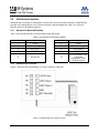
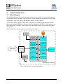
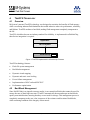
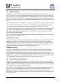
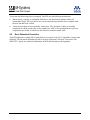
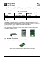
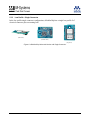
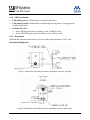
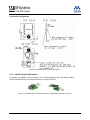
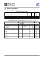
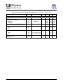
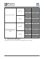
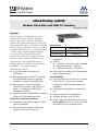
uDiskOnChip (uDOC) Modular Flash Disk with USB 2.0 Interface Data Sheet, July 2005 Highlights The performance of embedded systems in markets such as Single Board Computers (SBCs), thin clients, consumer electronics, Point Of Sale (POS) and telecom, is limited by IDE-based flash disks. A combination of higher capacity, higher performance devices is needed to support larger OSs, heavier GUI applications, a wide variety of installed applications and local data storage. uDiskOnChip (uDOC) answers these needs by merging M-Systems’ expertise in three worlds: the USB 2.0 highspeed interface, the DiskOnChip industrystandard flash for embedded systems, and the SuperMAP™ cryptographic engine. uDiskOnChip features: Exceptional read, write, and erase performance ® Built-in proprietary TrueFFS technology for full hard-disk emulation, high data reliability, and maximum flash lifetime Data integrity with Error Detection Code/Error Correction Code (EDC/ECC) based on a combination of BCH and Hamming algorithms Support for major embedded OSs, including Windows XP Embedded and Linux Protection and Security Features 1 Performance USB 2.0 High-Speed 20 MByte/sec Sustained Write 10 MByte/sec USB 2.0: 480 Mbit/sec high-speed USB compatible USB 1.1 12 Mbit/sec full-speed USB compatible Sustained Read rate: 1 MB/sec Sustained Write rate: 0.85 MB/sec Flash Interleave and Fly-By™ algorithm for improved performance Data Reliability SuperMAP cryptographic engine to enable protected partitions Data protected in hardware with digital signature: RSA with 64-byte key Sustained Read 4-bit Error Detection Code/Error Correction Code (EDC/ECC), based on a patented combination of BCH and Hamming code algorithms Guaranteed data integrity even after power loss Transparent bad-block management Dynamic and static wear-leveling Wear leveling algorithm that provides more than 5 million write/erase cycles for reliable data storage over an extended period Data Sheet, Rev. 2.2 94-SR-003-01-8L Operating Environment RoHS Support Any BIOS supporting boot from USB Mass Storage Class devices Can be used for boot and/or storage on the following operating systems: Windows XP Embedded Windows CE Windows Embedded for Point of Service (WEPOS) Linux VxWorks (storage only) Power Requirements 2 Operating temperature: Commercial: 0ºC to +70ºC Extended: -40ºC to +85ºC Storage temperature: -55ºC to +95ºC Capacities 32MB – 2GB Applications Horizontal alignment with mounting hole Horizontal alignment with 1x5 mechanical connector Low profile with mounting hole RoHS version available (all configurations) Environmental Power supply: 5VDC±10% Power consumption (Vcc=5V): Read/Write: 100 mA (typ) Suspend: <500 µA Packaging Embedded systems Single-board computers, Extended PCs Thin clients, network computers Set-top boxes Medical equipment Gaming uDiskOnChip Data Sheet, Rev. 2.2 94-SR-003-01-8L TABLE OF CONTENTS 1. Introduction ............................................................................................................................... 5 2. Product Overview ...................................................................................................................... 6 2.1 Product Description ............................................................................................................ 6 2.2 2x5 Electrical Interface ....................................................................................................... 7 2.2.1 Standard On-Board USB Header ......................................................................................... 7 2.2.2 uDiskOnChip Connector....................................................................................................... 7 3. Theory of Operation .................................................................................................................. 8 3.1 Block Diagram .................................................................................................................... 8 3.2 System Architecture ........................................................................................................... 9 3.2.1 Controller Internal Components ........................................................................................... 9 3.2.2 Controller External Components .......................................................................................... 9 4. TrueFFS Technology............................................................................................................... 10 4.1 Overview........................................................................................................................... 10 4.2 Bad-Block Management ................................................................................................... 10 4.3 Wear-Leveling .................................................................................................................. 11 4.4 Power Failure Management ............................................................................................. 11 4.5 Error Detection/Correction................................................................................................ 12 5. Specifications .......................................................................................................................... 13 5.1 Standards Compliance ..................................................................................................... 13 5.2 Environmental................................................................................................................... 13 5.3 5.4 3 5.2.1 Temperature ....................................................................................................................... 13 5.2.2 Shock and Vibration ........................................................................................................... 13 5.2.3 Mean Time Between Failures (MTBF) ............................................................................... 13 Mechanical ....................................................................................................................... 14 5.3.1 Horizontal - Single Connector ............................................................................................ 14 5.3.2 Horizontal - Dual Connector ............................................................................................... 14 5.3.3 Low Profile - Single Connector........................................................................................... 15 5.3.4 LED Functionality ............................................................................................................... 16 5.3.5 Dimensions......................................................................................................................... 16 5.3.6 uDiskOnChip-to-USB Adapter............................................................................................ 17 Electrical Specifications.................................................................................................... 18 5.4.1 Absolute Maximum Ratings................................................................................................ 18 5.4.2 DC Characteristics ............................................................................................................. 18 uDiskOnChip Data Sheet, Rev. 2.2 94-SR-003-01-8L 6. Software Description .............................................................................................................. 20 6.1 6.2 Microsoft Windows XP Embedded Modes ....................................................................... 20 6.1.1 Windows XP Embedded Storage ....................................................................................... 20 6.1.2 Windows XP Embedded Boot ............................................................................................ 20 6.1.3 Windows XP Embedded Secure Boot................................................................................ 20 Linux Modes ..................................................................................................................... 21 6.2.1 Linux Storage ..................................................................................................................... 21 6.2.2 Linux Boot........................................................................................................................... 21 7. Ordering Information............................................................................................................... 22 7.1 uDiskOnChip .................................................................................................................... 22 7.2 uDiskOnChip-to-USB Adapter .......................................................................................... 23 How to Contact Us ........................................................................................................................ 24 4 uDiskOnChip Data Sheet, Rev. 2.2 94-SR-003-01-8L 1. INTRODUCTION This data sheet includes the following sections: Section 1: Overview of data sheet contents Section 2: Product overview, including brief product description, interface diagram and header/connector descriptions Section 3: Theory of operation for the major building blocks Section 4: Description of TrueFFS technology Section 5: Environmental, mechanical and electrical specifications Section 6: Description of the available software components Section 7: Ordering information for uDiskOnChip For additional information on M-Systems’ flash disk products, please contact one of the offices listed on the back page. 5 uDiskOnChip Data Sheet, Rev. 2.2 94-SR-003-01-8L 2. PRODUCT OVERVIEW 2.1 Product Description uDiskOnChip (uDOC) is the ideal data storage device in any USB-capable system, capitalizing on M-Systems’ expertise in three fields: The USB interface (based on its USB flash drive), flash drives for the embedded market (based on the DiskOnChip product line), and security (based on patented algorithms). uDiskOnChip offers the speed and ease of the USB interface. uDiskOnChip can work with any operating system that supports USB Mass Storage Class devices, such as Windows XP Embedded, Windows CE, Linux, and others. M-Systems’ patented TrueFFS flash management technology, which fully emulates a hard disk in DiskOnChip products, is embedded in the uDiskOnChip firmware to streamline integration efforts. This transparent file system management enables read/write operations that are identical to a standard, sector-based hard disk. In addition, TrueFFS employs patented methods, such as virtual mapping, dynamic and static wear-leveling, and automatic block management to ensure high data reliability and to maximize flash life expectancy. Data integrity is guaranteed through an embedded 4-bit error detection and error correction code algorithm that automatically detects and corrects data errors. The EDC/ECC algorithm is based on a combination of Hamming and BCH code. uDiskOnChip provides data protection in hardware, utilizing RSA with a 64-byte key. This feature is enabled by the SuperMAP cryptographic engine developed by M-Systems’ Fortress division and used successfully in thousands of smartcards. uDiskOnChip is based on Single Level Cell (SLC) NAND flash technology. This technology is superior in its data storage characteristics, featuring the industry’s highest performance. Additionally, NAND flash technology is known for its high density and small die size, with the related cost and real estate benefits. Multi-Level Cell (MLC) NAND is planned for use in the next-generation product, enabling further cost benefits. uDiskOnChip is available in capacities ranging from 32MB to 2GB with a fast and simple upgrade path. It fits easily into any platform with an embedded USB connector, and can be secured firmly into place for enhanced ruggedness. 6 uDiskOnChip Data Sheet, Rev. 2.2 94-SR-003-01-8L 2.2 2x5 Electrical Interface uDiskOnChip is available in a horizontal version with a 2x5-pin electrical interface. uDiskOnChip provides two configurations; a 2x5 electrical interface plus mounting hole, and a 2x5 electrical interface plus 1x5 mechanical interface. 2.2.1 Standard On-Board USB Header Table 1 lists the host interface on-board header pins and signals. Table 1: Host Interface 2x5 On-Board Header Pin Signal Pin Signal 1 +5VDC 2 +5VDC 3 USB1 Data(-) 4 USB2 Data(-) 5 USB1 Data(+) 6 USB2 Data(+) 7 GND 8 GND 10 NC (future option in the Low Profile configuration: Write Protection signal) 9 2.2.2 Key (no pin) uDiskOnChip Connector Figure 1 illustrates the uDiskOnChip 2x5 device interface connector. Figure 1: uDiskOnChip 2x5 Connector Pinout 7 uDiskOnChip Data Sheet, Rev. 2.2 94-SR-003-01-8L 3. THEORY OF OPERATION 3.1 Block Diagram The uDiskOnChip controller enables the highest performance for USB 2.0, coupled with the best security and reliability available. The controller’s firmware inherently supports multi-vendor flash components to provide flexibility and guarantee delivery to our customers. As with other products based on M-Systems’ technology, the uDiskOnChip controller contains M-Systems’ patented USB device interface, which is compatible with USB 2.0. The controller also has a high-speed 32-bit RISC microcontroller with Idle and Deep Power-Down modes for power management. The uDiskOnChip controller architecture is illustrated in Figure 2. LEDs Xtal GPIO Timers and Counters ARM-7TDMI 32-bit RISC CPU USB Controller USB Connector Crypto-Core Voltage Regulator Reset Mechanism Multi-Layer Bus USB Protocol Clock Mechanism M-Systems Flash Controller NAND Flash SRAM ROM uDiskOnChip Controller Figure 2: uDiskOnChip Controller Block Diagram 8 uDiskOnChip Data Sheet, Rev. 2.2 94-SR-003-01-8L 3.2 System Architecture 3.2.1 Controller Internal Components • ARM7TDMI CPU, which serves as the hardware infrastructure for the M-Systems flash controller algorithm. • M-Systems Flash Controller, the heart of the system, which is responsible for the flash-handling algorithm, flash timing, and Error Detection and Correction. • USB (PHY and Digital) Controller, embedded in the uDiskOnChip controller, which interfaces with all external interactions via an external USB connector. • Crypto-Core, the hardware engine that provides security functions and services to be used by the controller. • SRAM, for running the controller program faster and more efficiently. • ROM, for running the boot code and additional service program. • Clock Mechanism, which drives all clock sources, some from the crystal oscillator and others from the PHY PLL. • Reset Mechanism, which restores the reset states of the system, and forces the controller to perform the boot procedure. The Reset state causes all cores to move to Reset mode. • Timers and Counters, including the device timer, watchdog, and general-purpose timer/counter channels. 3.2.2 Controller External Components • NAND Flash for data storage. • Crystal Oscillator 12.000 MHz, the main clock source. • 3.3V Voltage Regulator to supply a stable power supply to the circuit and for accurate and reliable operation. • LEDs for indicating controller activity. 9 uDiskOnChip Data Sheet, Rev. 2.2 94-SR-003-01-8L 4. TRUEFFS TECHNOLOGY 4.1 Overview M-Systems’ patented TrueFFS technology was designed to maximize the benefits of flash memory while overcoming inherent flash limitations that would otherwise reduce its performance, reliability, and lifetime. TrueFFS emulates a hard disk, making flash management completely transparent to the OS. TrueFFS, which has become an industry standard for reliability, is implemented in uDiskOnChip, therefore no integration is required. Application OS File System uDiskOnChip TrueFFS Figure 3: TrueFFS Implemented in uDiskOnChip Firmware TrueFFS technology features: • Flash file system management • Bad-block management • Dynamic virtual mapping • Dynamic and static wear-leveling • Power failure management • Implementation of MLC-tailored EDC/ECC • Performance optimization 4.2 Bad-Block Management Since NAND flash is an imperfect storage media, it can contain bad blocks that cannot be used for storage because of their high error rates. TrueFFS automatically detects and maps out bad blocks upon system initialization, ensuring that they are not used for storage. This management process is completely transparent to the user, who is unaware of the existence and location of bad blocks, while remaining confident of the integrity of data stored. 10 uDiskOnChip Data Sheet, Rev. 2.2 94-SR-003-01-8L 4.3 Wear-Leveling Flash memory can be erased a limited number of times. This number is called the erase cycle limit, or write endurance limit, and is defined by the flash array vendor. The erase cycle limit applies to each individual erase block in the flash device. In uDiskOnChip, the erase cycle limit of the flash is 100,000 erase cycles. This means that after approximately 100,000 erase cycles, the erase block begins to generate storage errors at a rate significantly higher than the error rate that is typical to the flash. In a typical application, and especially if a file system is used, specific pages are constantly updated (e.g., the page/s that contain the FAT, registry, etc.). Without any special handling, these pages would wear out more rapidly than other pages, reducing the lifetime of the entire flash. To overcome this inherent deficiency, TrueFFS uses M-Systems’ patented wear-leveling algorithm. This wear-leveling algorithm ensures that consecutive writes of a specific sector are not written physically to the same page in the flash. This spreads flash media usage evenly across all pages, thereby maximizing flash lifetime. M-Systems’ wear-leveling mechanism provides more than 5 million write/erase cycles for reliable data storage over an extended period. Dynamic Wear-Leveling TrueFFS uses statistical allocation to perform dynamic wear-leveling on newly written data. This minimizes the number of erase cycles per block. As a block erase is the most time-consuming operation, dynamic wear-leveling has a major impact on overall performance. This impact cannot be noticed during the first write to flash (since there is no need to erase blocks beforehand), but becomes more and more noticeable as the flash media becomes full. Static Wear-Leveling Areas on the flash media may contain static files, characterized by blocks of data that remain unchanged for very long periods of time, or even for the whole device lifetime. If wear-leveling were only applied on newly written pages, static areas would never be cycled. This limited application of wear-leveling would lower life expectancy significantly in cases where flash memory contains large static areas. To overcome this problem, TrueFFS forces data transfer in static areas as well as in dynamic areas, thereby applying wear-leveling to the entire media. 4.4 Power Failure Management TrueFFS uses algorithms based on erase after write instead of erase before write to ensure data integrity during normal operation and in the event of a power failure. Used areas are reclaimed for erasing and writing the flash management information into them only after an operation is complete. This procedure serves as a check on data integrity. The erase-after-write algorithm is also used to update and store mapping information on the flash memory. This keeps the mapping information coherent even during power failures. The only mapping information held in RAM is a table pointing to the location of the actual mapping information. This table is reconstructed during power-up or after reset from the information stored in the flash memory. 11 uDiskOnChip Data Sheet, Rev. 2.2 94-SR-003-01-8L To prevent data from being lost or corrupted, TrueFFS uses the following mechanisms: • When writing, copying, or erasing the flash device, the data format remains valid at all intermediate stages. Previous data is never erased until the operation has been completed and the new data has been verified. • A data sector cannot exist in a partially written state. The operation is either successfully completed, in which case the new sector contents are valid, or the operation has not yet been completed or has failed, in which case the old sector contents remain valid. 4.5 Error Detection/Correction TrueFFS implements a unique MLC-tailored Error Correction Code (ECC) algorithm to ensure data reliability. The advanced algorithm provides 4-bit Error Detection Code/Error Correction Code (EDC/ECC), based on a patented combination of BCH and Hamming code algorithms. 12 uDiskOnChip Data Sheet, Rev. 2.2 94-SR-003-01-8L 5. SPECIFICATIONS 5.1 Standards Compliance uDiskOnChip complies with CE requirements and FCC standards, and has been approved by the UL organization. uDiskOnChip is also available in lead-free versions (all configurations), which comply with the RoHS directive. 5.2 Environmental 5.2.1 Temperature Operating Commercial: 0ºC to +70ºC Extended: -40ºC to +85ºC Storage Extended: -55ºC to +95ºC 5.2.2 Shock and Vibration Table 2: Shock/Vibration Testing for uDiskOnChip Reliability Test Test Conditions Reference Standards Vibration 10 Hz to 500 Hz, 5 g, 3 axes, 30 minutes IEC 68-2-6 Mechanical Shock Duration: 11 ms, 50 g, 3 axes, 18 times IEC 68-2-27 5.2.3 Mean Time Between Failures (MTBF) The reliability figure of merit most often used for electronic equipment is Mean Time Between Failures (MTBF). M-Systems estimates MTBF using a prediction methodology based on reliability data for the individual components in M-Systems products. Component data comes from several sources: device life tests, failure analysis of earlier equipment, device physics, and field returns. M-Systems uses following methods to predict reliability: • Telcordia Special Report SR-332, Reliability Prediction Procedure for Electronic Equipment (RPP). • British Telecom Industry HRD5, Handbook of Reliability Data for Electronic Components used in Telecommunication System. Table 3 summarizes the MTBF prediction results for various uDiskOnChip configurations. The analysis was performed using a RAM Commander™ failure rate prediction. • 13 Failure Rate: The total number of failures within an item population, divided by the total number of life units expended by that population, during a particular measurement interval under stated condition. uDiskOnChip Data Sheet, Rev. 2.2 94-SR-003-01-8L • Mean Time Between Failures (MTBF): A basic measure of reliability for repairable items: The mean number of life units during which all parts of the item perform within their specified limits, during a particular measurement interval under stated conditions. Table 3: uDiskOnChip MTBF Condition MTBF (Hours) Failure Rate per Million Hours 64/128MB Telcordia SR-332, GB, 25°C 4,667,755 0.214 256/512/1024/2048MB Telcordia SR-332, GB, 25°C 4,130,674 0.24 64/128MB Telcordia SR-332, GF, 35°C 1,667,189 0.599 256/512/1024/2048MB Telcordia SR-332, GF, 35°C 1,360,977 0.735 Product 5.3 Mechanical uDiskOnChip is offered in a horizontal version with two available configurations and in a Low Profile version, as described below. In addition, an adapter is available (described in Section 5.3.6) to enable customers to evaluate uDiskOnChip using an external USB port. 5.3.1 Horizontal - Single Connector In the single connector configuration, uDiskOnChip has a single 2x5 electrical connector plus a mounting hole, as shown in Figure 4. Figure 4: uDiskOnChip Horizontal Version with Single Connector 5.3.2 Horizontal - Dual Connector In the dual connector configuration, uDiskOnChip has a 2x5 electrical connector, along with a 1x5 mechanical connector for mounting stability, as shown in Figure 5. Figure 5: uDiskOnChip Horizontal Version with Dual Connector Configuration 14 uDiskOnChip Data Sheet, Rev. 2.2 94-SR-003-01-8L 5.3.3 Low Profile - Single Connector In the low profile single connector configuration, uDiskOnChip has a single low-profile 2x5 electrical connector plus a mounting hole. (Side View) (Bottom View) (Top View) Figure 6: uDiskOnChip Horizontal Version with Single Connector 15 uDiskOnChip Data Sheet, Rev. 2.2 94-SR-003-01-8L 5.3.4 LED Functionality • LED flashing slowly: uDiskOnChip is connected and inactive • LED flashing rapidly: uDiskOnChip is transmitting/receiving data or is engaged in the identification process • Default LED colors: o Red: USB high-speed mode (10 MB/sec write, 20 MB/sec read) o Green: USB full-speed mode (0.85 MB/sec write, 1 MB/sec read) 5.3.5 Dimensions uDiskOnChip mechanical dimensions are in mm, with a general tolerance of ±0.25 mm. Horizontal Configuration Figure 7: uDiskOnChip 2x5 Horizontal Version, Single/Dual Connector, Top View Figure 8: uDiskOnChip 2x5 Horizontal Version, Single/Dual Connector, Bottom View 16 uDiskOnChip Data Sheet, Rev. 2.2 94-SR-003-01-8L Low Profile Configuration Figure 9: uDiskOnChip 2x5 Low Profile Version 5.3.6 uDiskOnChip-to-USB Adapter An adapter is available to assist customers in evaluating uDiskOnChip. The adapter enables inserting uDiskOnChip in an external desktop or laptop USB port. Figure 10: uDiskOnChip 2x5 Horizontal Version, Single/Dual Connector, Top View 17 uDiskOnChip Data Sheet, Rev. 2.2 94-SR-003-01-8L 5.4 Electrical Specifications 5.4.1 Absolute Maximum Ratings Table 4: Absolute Maximum Ratings Parameter Symbol Min Max Unit Ambient Operating Temperature Range (Commercial) TA 0 70 °C Ambient Operating Temperature Range (Extended) TA -40 85 °C Power Supply Voltage Relative to Ground Vbus 4 6 V Voltage level on D+ / D- Relative to Ground 3 Vdata -1 4.6 V 5.4.2 DC Characteristics Table 5: DC Characteristics for Full-Speed Operation (TA = 25°C,VDD = 3.3v, VSS = 0V) Parameter Symbol Test Conditions Min Typ Max Unit 4.40 5.00 5.25 V 87 <500 100 <500 mA µA 105 mA USB Signals Supply Voltage: VBUS Supply Current (RMS): -- Operating Suspend Icc Iccs VBUS=5.0v -- Max Current Consumption (Peak Value) Input Levels USB Signals (D+, D-): Low High VIL VIH --- -2.0 --- 0.8 -- V V VOL VOH RL of 1.5 kΩ to 3.6V RL of 15 kΩ to GND 0 2.6 --- 0.4 3.6 V V 2.0 V Output Voltage USB Signals (D+, D-): Low High Output Signal Crossover Voltage USB Signals (D+, D-) 18 VCRS uDiskOnChip Data Sheet, Rev. 2.2 1.3 94-SR-003-01-8L Table 6: DC Characteristics for High-Speed Operation (TA = 25°C,VDD = 3.3v, VSS = 0V) Parameter Symbol Test Conditions Min Typ Max Unit 4.40 5.00 5.25 V 100 <500 120 <500 mA µA 150 mA USB Signals Supply Voltage: VBUS Supply Current (RMS) -- Operating Suspend Icc Iccs VBUS=5.0v -- Max Current Consumption (Peak Value) Input Levels USB Signals (D+, D-): Low High VIL VIH --- -2.0 --- 0.8 -- V V VOL VOH RL of 1.5 kΩ to 3.6V RL of 15 kΩ to GND 0 2.6 --- 0.4 3.6 V V 2.0 V Output Voltage USB Signals (D+, D-): Low High Output Signal Crossover Voltage USB Signals (D+, D-): 19 VCRS uDiskOnChip Data Sheet, Rev. 2.2 1.3 94-SR-003-01-8L 6. SOFTWARE DESCRIPTION uDiskOnChip is available in five software configurations, three under Microsoft Windows XP Embedded, and two under Linux. 6.1 Microsoft Windows XP Embedded Modes 6.1.1 Windows XP Embedded Storage This is the uDiskOnChip default software mode. In Windows XP Embedded Storage mode, uDiskOnChip is recognized as removable memory in the system and is used as additional drive without any software integration process. Drive partitioning is not available in Windows XP Embedded Storage mode. 6.1.2 Windows XP Embedded Boot In Windows XP Embedded Boot mode, uDiskOnChip is recognized as a hard drive in the system. The system can boot from uDiskOnChip this mode, eliminating the need for additional components. In Windows XP Embedded Boot mode, uDiskOnChip can be partitioned into up to four drives: • First partition: Stores the Windows XP Embedded image • Other partitions: Store data and/or applications To set uDiskOnChip and the host to work in Windows XP Embedded Boot mode, please contact M-Systems technical support. M-Systems will provide a software package, including all required user manuals, for use in configuring uDiskOnChip to function in Windows XP Embedded Boot mode and function as the system boot device. In Windows XP Embedded Boot mode, the user can read from or write to all partitions. 6.1.3 Windows XP Embedded Secure Boot Windows XP Embedded Secure Boot mode provides uDiskOnChip customers with the advantage of M-Systems’ security capabilities, which implement unparalleled security algorithms in hardware using SuperMAP technology. M-Systems’ security technology is supported by over 15 patents, and field tested in tens of millions of smartcards. Some customization may be required to set uDiskOnChip and the host to work in Windows XP Embedded Secure Boot mode. M-Systems’ technical support department can provide a software package, including all required user manuals, for use in configuring uDiskOnChip to function as a secure system boot device. In Windows XP Embedded Secure Boot mode, uDiskOnChip can be partitioned into up to six drives, with a maximum of two secure drives and four standard drives. The secure drives are write protected using Public Key Infrastructure (PKI) for key exchange and authentication (implemented by an RSA 64-byte key). In addition, uDiskOnChip supports the Enhanced Write Filter (enabling Microsoft EWF). 20 uDiskOnChip Data Sheet, Rev. 2.2 94-SR-003-01-8L It is recommended to partition uDiskOnChip as follows when using Windows XP Embedded Secure Boot mode: • Secure partition I: This drive stores the Windows XP Embedded operating system image. • Secure partition II (optional): This drive can function as a secure storage area for data that should not be accessed by unauthorized users • Standard partition: Up to four standard drives that are not write protected 6.2 Linux Modes 6.2.1 Linux Storage This is the uDiskOnChip default software mode. In Linux Storage mode, uDiskOnChip is used as additional drive without any software integration process. In Linux Storage mode, uDiskOnChip can be partitioned into up to four drives. 6.2.2 Linux Boot Please contact M-Systems’ technical support department to set uDiskOnChip and the host to work in Linux Boot mode. M-Systems will provide a user manual for use in configuring uDiskOnChip to function as a system boot device. In Linux Boot mode, uDiskOnChip can be partitioned into up to four drives. Table 7: uDiskOnChip Software Modes Windows XP Embedded Mode Partition Type Linux Functionality Partition Type Removable Storage (up to four partitions) Boot and storage (up to four partitions) Storage Storage Boot Partition 1: Boot Partitions 2-4: Storage Fixed Partition 1: Boot, write protected with RSA OS Protection: Enhanced Write Filter Fixed - Partition 2: Storage, write protected with RSA Fixed - Partitions 3-6: Storage (read/write) Fixed - Secure Boot 21 uDiskOnChip Data Sheet, Rev. 2.2 94-SR-003-01-8L 7. ORDERING INFORMATION 7.1 uDiskOnChip MD16x5-Dxxxx-J-T-P RoHS Support Device Code Density Mechanical Support Environmental 1665: uDiskOnChip Horizontal D: MBytes Blank: Mounting hole Blank: Commercial Blank: Standard P: Lead free 1675: uDiskOnChip Low Profile xxxx: Value J: 1x5 mechanical connector X: Extended Figure 11: Ordering Information Structure Table 8: uDiskOnChip Form Factors and Ordering Information Configuration Temperature Range Capacity (MB) Ordering Information 32 64 128 256 512 1024 2048 32 64 128 256 512 1024 2048 32 64 128 256 512 1024 2048 32 64 128 256 512 1024 2048 MD1665-D32 MD1665-D64 MD1665-D128 MD1665-D256 MD1665-D512 MD1665-D1024 MD1665-D2048 MD1665-D32-X MD1665-D64-X MD1665-D128-X MD1665-D256-X MD1665-D512-X MD1665-D1024-X MD1665-D2048-X MD1665-D32-P MD1665-D64-P MD1665-D128-P MD1665-D256-P MD1665-D512-P MD1665-D1024-P MD1665-D2048-P MD1665-D32-X-P MD1665-D64-X-P MD1665-D128-X-P MD1665-D256-X-P MD1665-D512-X-P MD1665-D1024-X-P MD1665-D2048-X-P Commercial Horizontal with single connector and mounting hole Extended Commercial Horizontal with single connector and mounting hole (PB Free Version) Extended 22 uDiskOnChip Data Sheet, Rev. 2.2 94-SR-003-01-8L Commercial Horizontal with dual connector Extended Commercial Low Profile with single connector and mounting hole (PB Free version) Extended 7.2 32 64 128 256 512 1024 2048 32 64 128 256 512 1024 2048 32 64 128 256 512 1024 2048 32 64 128 256 512 1024 2048 MD1665-D32-J MD1665-D64-J MD1665-D128-J MD1665-D256-J MD1665-D512-J MD1665-D1024-J MD1665-D2048-J MD1665-D32-J-X MD1665-D64-J-X MD1665-D128-J-X MD1665-D256-J-X MD1665-D512-J-X MD1665-D1024-J-X MD1665-D2048-J-X MD1675-D32-P MD1675-D64-P MD1675-D128-P MD1675-D256-P MD1675-D512-P MD1675-D1024-P MD1675-D2048-P MD1675-D32-X-P MD1675-D64-X-P MD1675-D128-X-P MD1675-D256-X-P MD1675-D512-X-P MD1675-D1024-X-P MD1675-D2048-X-P uDiskOnChip-to-USB Adapter Ordering information for the uDiskOnChip-to-USB adapter: UDOC-2X5-ADPT 23 uDiskOnChip Data Sheet, Rev. 2.2 94-SR-003-01-8L HOW TO CONTACT US USA China M-Systems, Inc. 555 North Mathilda Avenue, Suite 220 Sunnyvale, CA 94085 Phone: +1-408-470-4440 Fax: +1-408-470-4470 M-Systems China Ltd. Room 121-122 Bldg. 2, International Commerce & Exhibition Ctr. Hong Hua Rd. Futian Free Trade Zone Shenzhen, China Phone: +86-755-8348-5218 Fax: +86-755-8348-5418 Japan Europe M-Systems Japan Inc. Asahi Seimei Gotanda Bldg., 3F 5-25-16 Higashi-Gotanda Shinagawa-ku Tokyo, 141-0022 Phone: +81-3-5423-8101 Fax: +81-3-5423-8102 M-Systems Ltd. 7 Atir Yeda St. Kfar Saba 44425, Israel Tel: +972-9-764-5000 Fax: +972-3-548-8666 Taiwan Internet M-Systems Asia Ltd. 14 F, No. 6, Sec. 3 Minquan East Road Taipei, Taiwan, 104 Tel: +886-2-2515-2522 Fax: +886-2-2515-2295 www.m-systems.com General Information [email protected] Sales and Technical Information [email protected] This document is for information use only and is subject to change without prior notice. M-Systems Flash Disk Pioneers Ltd. assumes no responsibility for any errors that may appear in this document. No part of this document may be reproduced, transmitted, transcribed, stored in a retrievable manner or translated into any language or computer language, in any form or by any means, electronic, mechanical, magnetic, optical, chemical, manual or otherwise, without prior written consent of M-Systems. M-Systems products are not warranted to operate without failure. Accordingly, in any use of the Product in life support systems or other applications where failure could cause injury or loss of life, the Product should only be incorporated in systems designed with appropriate and sufficient redundancy or backup features. Contact your local M-Systems sales office or distributor, or visit our website at www.m-sys.com to obtain the latest specifications before placing your order. © 2005 M-Systems Flash Disk Pioneers Ltd. All rights reserved. M-Systems, DiskOnChip, DiskOnChip Millennium, DiskOnKey, DiskOnKey MyKey, FFD, Fly-By, iDiskOnChip, iDOC, mDiskOnChip, mDOC, MegaSIM, Mobile DiskOnChip, SuperMAP, TrueFFS, uDiskOnChip, uDOC, and Xkey are trademarks or registered trademarks of M-Systems Flash Disk Pioneers, Ltd. Other product names or service marks mentioned herein may be trademarks or registered trademarks of their respective owners and are hereby acknowledged. All specifications are subject to change without prior notice. 24 uDiskOnChip Data Sheet, Rev. 2.2 94-SR-003-01-8L