1
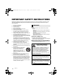
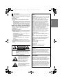
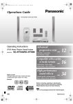
SC-HTB370PPC_RQT9777-1P_mst.book Page 1 Tuesday, January 29, 2013 11:48 AM Owner’s Manual Home Theater Audio System Model No. SC-HTB370 Thank you for purchasing this product. Please read these instructions carefully before using this product, and save this manual for future use. If you have any questions, contact: U.S.A. and Puerto Rico: 1-800-211-PANA (7262) Canada: 1-800-561-5505 Register online at www.panasonic.com/register (U.S. customers only) P PC RQT9777-1P until 2012/12/27 SC-HTB370PPC_RQT9777-1P_mst.book Page 2 Tuesday, January 29, 2013 11:48 AM IMPORTANT SAFETY INSTRUCTIONS Read these operating instructions carefully before using the unit. Follow the safety instructions on the unit and the applicable safety instructions listed below. Keep these operating instructions handy for future reference. 1 2 3 4 5 6 7 8 9 10 11 12 13 14 2 Read these instructions. Keep these instructions. Heed all warnings. Follow all instructions. Do not use this apparatus near water. Clean only with dry cloth. Do not block any ventilation openings. Install in accordance with the manufacturer’s instructions. Do not install near any heat sources such as radiators, heat registers, stoves, or other apparatus (including amplifiers) that produce heat. Do not defeat the safety purpose of the polarized or grounding-type plug. A polarized plug has two blades with one wider than the other. A grounding-type plug has two blades and a third grounding prong. The wide blade or the third prong are provided for your safety. If the provided plug does not fit into your outlet, consult an electrician for replacement of the obsolete outlet. Protect the power cord from being walked on or pinched particularly at plugs, convenience receptacles, and the point where they exit from the apparatus. Only use attachments/accessories specified by the manufacturer. Use only with the cart, stand, tripod, bracket, or table specified by the manufacturer, or sold with the apparatus. When a cart is used, use caution when moving the cart/ apparatus combination to avoid injury from tip-over. Unplug this apparatus during lightning storms or when unused for long periods of time. Refer all servicing to qualified service personnel. Servicing is required when the apparatus has been damaged in any way, such as power-supply cord or plug is damaged, liquid has been spilled or objects have fallen into the apparatus, the apparatus has been exposed to rain or moisture, does not operate normally, or has been dropped. RQT9777 WARNING Unit ≥ To reduce the risk of fire, electric shock or product damage, j Do not expose this unit to rain, moisture, dripping or splashing. j Do not place objects filled with liquids, such as vases, on this unit. j Use only the recommended accessories. j Do not remove covers. j Do not repair this unit by yourself. Refer servicing to qualified service personnel. AC power supply cord ≥ The power plug is the disconnecting device. Install this unit so that the power plug can be unplugged from the socket outlet immediately. Button-type battery (Lithium battery) ≥ Risk of fire, explosion and burns. Do not disassemble, heat above 60 oC (140 oF) or incinerate. DO NOT INGEST BATTERY, CHEMICAL BURN HAZARD This product contains a coin/button cell battery. If the coin/button cell battery is swallowed, it can cause severe internal burns in just 2 hours and can lead to death. Keep new and used batteries away from children. If the battery compartment does not close securely, stop using the product and keep it away from children. If you think batteries might have been swallowed or placed inside any part of the body, seek immediate medical attention. If any electrolyte should come into contact with your hands or clothes, wash it off thoroughly with water. If any electrolyte should come into contact with your eyes, never rub the eyes. Rinse eyes thoroughly with water, and then consult a doctor. <For USA-California only> This product contains a CR Coin Cell Lithium Battery which contains Perchlorate Material s special handling may apply. See www.dtsc.ca.gov/hazardouswaste/perchlorate. Page 3 Tuesday, January 29, 2013 CAUTION THE FOLLOWING APPLIES ONLY IN THE U.S.A. FCC Note: Unit ≥ Do not place sources of naked flames, such as lighted candles, on this unit. This equipment has been tested and found to comply with the limits for a Class B digital device, pursuant to Part 15 of the FCC Rules. These limits are designed to provide reasonable protection against harmful interference in a residential installation. This equipment generates, uses and can radiate radio frequency energy and, if not installed and used in accordance with the instructions, may cause harmful interference to radio communications. However, there is no guarantee that interference will not occur in a particular installation. If this equipment does cause harmful interference to radio or television reception, which can be determined by turning the equipment off and on, the user is encouraged to try to correct the interference by one or more of the following measures: ≥ Reorient or relocate the receiving antenna. ≥ Increase the separation between the equipment and receiver. ≥ Connect the equipment into an outlet on a circuit different from that to which the receiver is connected. ≥ Consult the dealer or an experienced radio/TV technician for help. Any unauthorized changes or modifications to this equipment would void the user’s authority to operate this device. This device complies with Part 15 of the FCC Rules. Operation is subject to the following two conditions: (1) This device may not cause harmful interference, and (2) this device must accept any interference received, including interference that may cause undesired operation. Responsible Party: Panasonic Corporation of North America One Panasonic Way, Secaucus, NJ 07094 Support Contact: Panasonic Consumer Marketing Company of North America Telephone No.: 1-800-211-PANA (7262) Placement ≥ To reduce the risk of fire, electric shock or product damage, j Do not install or place this unit in a bookcase, built-in cabinet or in another confined space. Ensure this unit is well ventilated. j Do not obstruct this unit’s ventilation openings with newspapers, tablecloths, curtains, and similar items. Button-type battery (Lithium battery) ≥ Danger of explosion if battery is incorrectly replaced. Replace only with the type recommended by the manufacturer. ≥ Keep out of reach of children. ≥ Insert with poles aligned. ≥ Mishandling of batteries can cause electrolyte leakage and may cause a fire. j Remove the battery if you do not intend to use the remote control for a long period of time. Store in a cool, dark place. j Do not heat or expose to flame. j Do not leave the battery(ies) in a car exposed to direct sunlight for a long period of time with doors and windows closed. j Do not touch the terminals (i and j) with metal objects. j Do not recharge, disassemble, remodel, heat or throw into fire. ≥ When disposing the batteries, please contact your local authorities or dealer and ask for the correct method of disposal. CAUTION RISK OF ELECTRIC SHOCK DO NOT OPEN CAUTION: TO REDUCE THE RISK OF ELECTRIC SHOCK, DO NOT REMOVE SCREWS. NO USER-SERVICEABLE PARTS INSIDE. REFER SERVICING TO QUALIFIED SERVICE PERSONNEL. The lightning flash with arrowhead symbol, within an equilateral triangle, is intended to alert the user to the presence of uninsulated “dangerous voltage” within the product’s enclosure that may be of sufficient magnitude to constitute a risk of electric shock to persons. The exclamation point within an equilateral triangle is intended to alert the user to the presence of important operating and maintenance (servicing) instructions in the literature accompanying the appliance. 11:48 AM THE FOLLOWING APPLIES ONLY IN CANADA. This device complies with RSS-GEN, RSS-210 of the IC Rules. Operation is subject to the following two conditions: (1) This device may not cause harmful interference, (2) This device must accept any interference received, including interference that may cause undesired operation of the device. ‘ THE FOLLOWING APPLIES IN THE U.S.A. AND CANADA This transmitter must not be co-located or operated in conjunction with any other antenna or transmitter. This equipment complies with FCC/IC radiation exposure limits set forth for an uncontrolled environment and meets the FCC radio frequency (RF) Exposure Guidelines in Supplement C to OET65 and RSS-102 of the IC radio frequency (RF) Exposure rules. This equipment has very low levels of RF energy that is deemed to comply without maximum permissive exposure evaluation (MPE). But it is desirable that it should be installed and operated keeping the radiator at least 20 cm (7 7/8q) or more away from person’s body (excluding extremities: hands, wrists, feet and ankles). RQT9777 3 Precautions SC-HTB370PPC_RQT9777-1P_mst.book SC-HTB370PPC_RQT9777-1P_mst.book Page 4 Tuesday, January 29, 2013 11:48 AM Table of contents IMPORTANT SAFETY INSTRUCTIONS ............................................................ 2 Before use Supplied items ................................................................................................... 5 This system (SC-HTB370).......................................................................................................... 5 Accessories ................................................................................................................................ 5 Control reference guide .................................................................................... 6 This system (Front)..................................................................................................................... 6 This system (Rear) ..................................................................................................................... 7 Remote control ........................................................................................................................... 8 Getting started Step 1 Selecting the placement method......................................................... 9 The speaker system ................................................................................................................. 10 The active subwoofer ............................................................................................................... 10 Wireless interference ................................................................................................................ 10 Step 2 Assembling the speakers................................................................... 11 When attaching the speakers to a wall ..................................................................................... 11 When placing the speakers on a table ..................................................................................... 16 Additional speaker fall prevention measures ............................................................................ 20 Step 3 Connections ........................................................................................ 22 Connection with the TV ............................................................................................................ Connection with other devices.................................................................................................. Speaker cable connection ........................................................................................................ AC power supply cord connection ............................................................................................ Active subwoofer wireless connection ...................................................................................... Bluetooth® connection .............................................................................................................. 22 22 23 23 24 24 Operations Using this system ............................................................................................ 25 3D sound .......................................................................................................... 26 Sound modes ........................................................................................................................... 26 Advanced operations ...................................................................................... 27 Reference Troubleshooting .............................................................................................. Specifications .................................................................................................. Unit care ........................................................................................................... About Bluetooth® ............................................................................................ Indicator illumination ...................................................................................... Limited Warranty (ONLY FOR U.S.A. AND PUERTO RICO) ................................................... Limited Warranty (ONLY FOR CANADA)....................................................... 4 RQT9777 29 30 32 32 33 34 35 SC-HTB370PPC_RQT9777-1P_mst.book Page 5 Tuesday, January 29, 2013 11:48 AM Before use ≥ The illustrations shown may differ from your unit. ≥ Operations in this Owner’s Manual are described mainly with the remote control, but you can perform the operations on the main unit if the controls are the same. Supplied items ∏ 2 Front speakers (SB-HTB570) Before use ∏ 1 Active subwoofer (SB-HWA370) Accessories Check the supplied accessories before using this system. ∏ 2 AC power supply ∏ 2 Speaker cables (REE1789: RED) cords (REE1790: WHITE) (K2CB2CB00022) Length: 3 m (9.8 ft) ∏ 1 Metal bracket (RML0761) ∏ 4 Screws (XYN5+J14FJK) ∏ 2 Speaker feet (RKAX0042-K) ∏ 2 Stand necks (RGK2444) ∏ 2 Leg stands (RGK2463) ∏ 2 Support legs (RGK2464) ∏ 2 Speaker bases (RGK2465) (ONLY FOR CANADA) The enclosed Canadian French label sheet corresponds to the English display on the remote control and the top and rear of the main unit and active subwoofer. Getting started ∏ 1 Remote control (with a battery) (N2QAYC000083) Reference Operations ∏ 1 Main unit (SU-HTB370) Precautions This system (SC-HTB370) ≥ Product numbers are correct as of December 2012. These may be subject to change. ≥ For U.S.A. and Puerto Rico: To order accessories, refer to “Accessory Purchases (United States and Puerto Rico)” on page 34. For Canada: To order accessories, call the dealer from whom you have made your purchase. ≥ The supplied AC power supply cord is for use with this system only. Do not use it with other equipment. Also, do not use cords from other equipment with this system. RQT9777 5 SC-HTB370PPC_RQT9777-1P_mst.book Page 6 Tuesday, January 29, 2013 11:48 AM Control reference guide This system (Front) 4 5 6 7 1 2 3 Main unit 1 Standby/on switch (Í/I) Press to switch the unit from on to standby mode or vice versa. In standby mode, the unit is still consuming a small amount of power. 2 3 Adjust the volume of this system Select the input source “TV”#“BD/DVD”#“AUX” 4 Input selector indicators§1 A Bluetooth® indicator Lights blue when the Bluetooth® device is the audio source B TV indicator Lights green when the TV is the audio source C BD/DVD indicator Lights amber when the device connected to the BD/DVD terminal is the audio source D AUX indicator Lights amber when the device connected to the AUX terminal is the audio source ^----------- “ 5 ”(---------} 6 7 Active subwoofer Sound mode indicators E STANDARD indicator Lights when STANDARD is the current sound mode F STADIUM indicator§2 Lights when STADIUM is the current sound mode G MUSIC indicator§2 Lights when MUSIC is the current sound mode H CINEMA indicator Lights when CINEMA is the current sound mode I NEWS indicator Lights when NEWS is the current sound mode J STEREO indicator Lights when STEREO is the current sound mode Remote control signal sensor (> 8) WIRELESS LINK indicator (> 24) §1 §1 The indicators will also blink in various conditions. (> 33) §2 The indicator blinks for 5 sec when the main unit detects an audio format. To manually verify the current audio format and the corresponding indicators, refer to page 27 (Audio format indicator). 6 RQT9777 SC-HTB370PPC_RQT9777-1P_mst.book Page 7 Tuesday, January 29, 2013 11:48 AM Before use This system (Rear) 1 2 3 4 AC IN terminal (> 23) Speaker terminals (> 23) TV terminal (> 22) BD/DVD terminal (> 22) 5 6 7 USB port (for service use only) AUX terminal (> 22) Active subwoofer on/off button (> 24) § The I/D SET button is only used when the main unit is not paired with the active subwoofer. (> 30) RQT9777 7 SC-HTB370PPC_RQT9777-1P_mst.book Page 8 Tuesday, January 29, 2013 11:48 AM Remote control ∫ Before using for the first time Remove the insulation sheet A. 3 1 2 4 DIALOG LEVEL ∫ To replace a button-type battery 5 INPUT SELECTOR 6 Battery type: CR2025 (Lithium battery) LINK MODE SOUND ----PAIRING 8 7 1 2 3 Turn the main unit on or off (> 25) Adjust the dialog effect level (> 25) Adjust the output level of the active subwoofer (bass sound) (> 25) Adjust the volume of this system (> 25) Mute the sound (> 25) Select the input source (> 25) “TV”#“BD/DVD”#“AUX” 4 5 6 ^----------- “ ”(---------} Select the Bluetooth® device as the source (> 25) Select the sound mode (> 26) “STANDARD” -----#“STADIUM” -----#“MUSIC” ^- “STEREO”( “NEWS”( “CINEMA”(} 7 8 ≥ Set the button-type battery with its (i) mark facing upward. ≥ Keep the button-type battery out of reach of children to prevent swallowing. ∫ Remote control operation range The remote control signal sensor is located on the main unit. ≥ Use the remote control within the correct operation range. B Remote control signal sensor ≥ Operation range Distance: Within approx. 7 m (23 ft) directly in front Angle: Approx. 30o left and right 8 RQT9777 SC-HTB370PPC_RQT9777-1P_mst.book Page 9 Tuesday, January 29, 2013 11:48 AM Step 1 Selecting the placement method Getting started ≥Choose a placement method that suits you best. When attaching the speakers to a wall Place the speakers horizontally Page 11 Before use Place the speakers vertically Page 14 Getting started When placing the speakers on a table Place the speakers using the leg stands Page 16 Place the speakers using the support legs and speaker feet Page 17 Place the speakers using the speaker bases Page 18 RQT9777 9 SC-HTB370PPC_RQT9777-1P_mst.book Page 10 Tuesday, January 29, 2013 11:48 AM Caution ≥ This system is to be used only as indicated in these instructions. Failure to do so may lead to damage to the amplifier and/or the speakers, and may result in the risk of fire. Consult a qualified service person if damage has occurred or if you experience a sudden change in performance. ≥ Do not attempt to attach the speakers to a wall using methods other than those described in this manual. The speaker system ≥Use a screwdriver (i) for assembling the speakers. ≥Do not hold the speakers in one hand to avoid injury, you may drop the speakers when carrying them. ∫ When attaching the speakers to a wall The wall or pillar on which the speakers are to be attached should be capable of supporting 33 kg (72.8 lbs) per screw. Consultation with a qualified installation specialist is recommended when attaching the speakers to a wall. Improper attachment may result in damage to the wall and speakers, and personal injury. ∫ When placing the speakers in front of the TV The speakers may block or interfere with the TV’s various sensors (C.A.T.S. (Contrast Automatic Tracking System) sensor, remote control sensor, etc.) and the 3D Eyewear transmitters on a 3D compatible TV. ≥ If the leg stands are being used Change the height of the leg stands and/or move the speakers further away from the TV. If the TV still does not function correctly, try removing the leg stands. ≥ If the leg stands are not used Move the speakers further away from the TV. If the TV still does not function properly, try placing them beside the TV (> 9). The active subwoofer When carrying the active subwoofer A Do not hold the active subwoofer from this opening. The parts inside may get damaged. B Always hold the bottom of the active subwoofer when moving it. A B Wireless interference To avoid interference, maintain the following distances between the main unit/active subwoofer and other electronic devices that use the same radio frequency (2.4 GHz band). C D C Main unit/active subwoofer D Wireless router, cordless phone and other electronic devices: approx. 2 m (6 1/2 ft) ≥ Place the active subwoofer within a few meters of the main unit and in a horizontal position with the top panel facing upward. ≥ Do not use the main unit or the active subwoofer in a metal cabinet. ≥ Placing the active subwoofer too close to the walls and corners can result in excessive bass. Cover walls and windows with thick curtains. ≥ If irregular coloring occurs on your TV, turn the TV off for about 30 minutes. If it persists, move the speakers further away from the TV. ≥ Keep magnetized items away. Magnetized cards, watches, etc., can be damaged if placed too close to the active subwoofer and the speakers. 10 RQT9777 SC-HTB370PPC_RQT9777-1P_mst.book Page 11 Tuesday, January 29, 2013 11:48 AM Step 2 Assembling the speakers When attaching the speakers to a wall Place the speakers horizontally The speakers can be wall mounted by drilling screws into the wall, etc. Make sure that the screw used and the wall are strong enough to support the weight of at least 33 kg (72.8 lbs). The screws and other items are not supplied as the type and size will vary with each installation. ≥For details about the required screws, refer to the diagram below the step “Drive a screw into the wall.” (> 12). ∏ 2 Speakers ∏ 2 Speaker cables WHITE: Left RED: Right ∏ 1 Metal bracket ∏ 2 Screws ≥For a safety measure to prevent the speakers from falling, refer to page 20. ≥To prevent damage or scratches, lay down a soft cloth and perform the assembly on it. Getting started Assemble the speakers. ≥ The two speakers are interchangeable. ≥ Keep the screws out of reach of children to prevent swallowing. A Screw (supplied) ≥ Tighten securely. RQT9777 11 SC-HTB370PPC_RQT9777-1P_mst.book Page 12 Tuesday, January 29, 2013 11:48 AM Connect the speaker cables. 1 Insert the wire fully. r: White s: Blue line 45 ≥ Insert the wire fully, taking care not to insert beyond the wire insulation. 2 Press into the groove. A Right speaker connector B Left speaker connector Push Red White § If you have difficulty inserting the cable, try straightening the speaker cable and then bending the cable about 20 mm (25/32q) from the tip, at an angle of approx. 45o (as illustrated above). Drive a screw into the wall. ≥ Use the measurements indicated below to identify the screwing positions on the wall. ≥ Leave at least 20 mm (25/32q) of space above and on each side of the speaker to allow enough space for fitting the speaker. ≥ Keep the screws out of reach of children to prevent swallowing. A B C D E At least 30 mm (1 3/16q) ‰4.0 mm (5/32q) ‰7.0 mm to ‰9.4 mm (9/32q to 3/8q) Wall or pillar 5.5 mm to 6.5 mm (7/32q to 1/4q) Front view (semi-transparent image) F 238 mm (9 3/8q) J Wall mounting hole 12 RQT9777 G 576 mm (22 11/16q) H 248 mm (9 3/4q) I 20 mm (25/32q) SC-HTB370PPC_RQT9777-1P_mst.book Page 13 Tuesday, January 29, 2013 11:48 AM Fit the speaker securely onto the screw(s). Red connector: The speaker attached to the red connector cable is to be placed on the right side. White Getting started White connector: The speaker attached to the white connector cable is to be placed on the left side. Red A Right speaker connector B Left speaker connector DO ≥ Move the speaker so that the screw is in this position. DO NOT ≥ In this position, the speaker will likely fall if moved to the left or right. RQT9777 13 SC-HTB370PPC_RQT9777-1P_mst.book Page 14 Tuesday, January 29, 2013 11:48 AM Place the speakers vertically The speakers can be wall mounted by drilling screws into the wall, etc. Make sure that the screw used and the wall are strong enough to support the weight of at least 33 kg (72.8 lbs). The screws and other items are not supplied as the type and size will vary with each installation. ≥For details about the required screws, refer to the diagram below the step “Drive a screw into the wall.” (> 15). ∏ 2 Speakers ∏ 2 Stand necks ∏ 2 Speaker cables WHITE: Left RED: Right ∏ 2 Screws ≥For a safety measure to prevent the speakers from falling, refer to page 20. ≥To prevent damage or scratches, lay down a soft cloth and perform the assembly on it. Attach the stand neck. ≥ The two speakers are interchangeable. ≥ Keep the screws out of reach of children to prevent swallowing. A Screw (supplied) ≥ Tighten securely. Connect the speaker cables. 1 Insert the wire fully. r: White s: Blue line ≥ Insert the wire fully, taking care not to insert beyond the wire insulation. Push 45 2 Press into the groove. § If you have difficulty inserting the cable, try straightening the speaker cable and then bending the cable about 20 mm (25/32q) from the tip, at an angle of approx. 45o (as illustrated above). 14 RQT9777 SC-HTB370PPC_RQT9777-1P_mst.book Page 15 Tuesday, January 29, 2013 11:48 AM Drive a screw into the wall. ≥ Use the measurements indicated below to identify the screwing positions on the wall. ≥ Leave at least 20 mm (25/32q) of space above and on each side of the speaker to allow enough space for fitting the speaker. ≥ Keep the screws out of reach of children to prevent swallowing. A B C D E F Front speaker (Rear view) G 100 mm (3 15/16q) H 436 mm (17 5/32q) I 34 mm (1 11/32q) J Wall mounting hole At least 30 mm (1 3/16q) ‰4.0 mm (5/32q) ‰7.0 mm to ‰9.4 mm (9/32q to 3/8q) Wall or pillar 5.5 mm to 6.5 mm (7/32q to 1/4q) Red connector: The speaker attached to the red connector cable is to be placed on the right side. White connector: The speaker attached to the white connector cable is to be placed on the left side. White Red K Left speaker connector DO ≥ Move the speaker so that the screw is in this position. L Right speaker connector DO NOT ≥ In this position, the speaker will likely fall if moved to the left or right. RQT9777 15 Getting started Fit the speaker(s) securely onto the screw(s). SC-HTB370PPC_RQT9777-1P_mst.book Page 16 Tuesday, January 29, 2013 11:48 AM When placing the speakers on a table Place the speakers using the leg stands ∏ 2 Speakers ∏ 2 Speaker cables WHITE: Left RED: Right ∏ 2 Leg stands ∏ 4 Screws ∏ 1 Metal bracket ≥For a safety measure to prevent the speakers from falling, refer to page 20. ≥To prevent damage or scratches, lay down a soft cloth and perform the assembly on it. Assemble the speakers following steps 1 and 2 of “Place the speakers horizontally” (> 11, 12). Attach the leg stands. Red connector: With the speaker facing down, the speaker attached to the red connector cable is to be placed on the left side. White connector: With the speaker facing down, the speaker attached to the white connector cable is to be placed on the right side. ≥ Keep the screws out of reach of children to prevent swallowing. White Red A Screw (supplied) ≥ Tighten securely. B Screw hole 16 RQT9777 Align the higher or lower holes with the projecting parts on the speaker. ≥ By changing the position that the stand is attached to the projecting parts, the height can be adjusted by 9 mm (11/32q). C Right speaker connector D Left speaker connector SC-HTB370PPC_RQT9777-1P_mst.book Page 17 Tuesday, January 29, 2013 11:48 AM Place the speakers using the support legs and speaker feet ∏ 2 Speakers ∏ 2 Speaker cables WHITE: Left RED: Right ∏ 1 Metal bracket ∏ 2 Support legs ∏ 4 Screws ∏ 2 Speaker feet ≥For a safety measure to prevent the speakers from falling, refer to page 20. ≥To prevent damage or scratches, lay down a soft cloth and perform the assembly on it. Assemble the speakers following steps 1 and 2 of “Place the speakers horizontally” (> 11, 12). Red connector: With the speaker facing down, the speaker attached to the red connector cable is to be placed on the left side. White connector: With the speaker facing down, the speaker attached to the white connector cable is to be placed on the right side. ≥ Keep the screws and the speaker feet out of reach of children to prevent swallowing. Align the projecting parts on the speaker with support leg. White Red A Screw (supplied) ≥ Tighten securely. B Screw hole C Speaker foot (supplied) D Right speaker connector E Left speaker connector RQT9777 17 Getting started Attach the support legs and speaker feet. SC-HTB370PPC_RQT9777-1P_mst.book Page 18 Tuesday, January 29, 2013 11:48 AM Place the speakers using the speaker bases ∏ 2 Speakers ∏ 2 Speaker cables WHITE: Left RED: Right ∏ 2 Speaker bases ∏ 4 Screws ∏ 2 Stand necks ≥For a safety measure to prevent the speakers from falling, refer to page 20. ≥To prevent damage or scratches, lay down a soft cloth and perform the assembly on it. Assemble the speakers following step 1 of “Place the speakers vertically” (> 14). Insert the speaker cable through the speaker base and connect the speaker cables. ≥ Be sure to insert the speaker cable through the threading hole as indicated in the illustration. 1 Insert the wire fully. r: White s: Blue line ≥ Insert the wire fully, taking care not to insert beyond the wire insulation. Push 2 Press into the groove. 45 § If you have difficulty inserting the cable, try straightening the speaker cable and then bending the cable about 20 mm (25/32q) from the tip, at an angle of approx. 45o (as illustrated above). 18 RQT9777 SC-HTB370PPC_RQT9777-1P_mst.book Page 19 Tuesday, January 29, 2013 11:48 AM Attach the speaker base. ≥ The two speakers are interchangeable. ≥ Keep the screws out of reach of children to prevent swallowing. Screw (supplied) ≥ Tighten securely. Press into the groove. Red connector: The speaker attached to the red connector cable is to be placed on the right side. White connector: The speaker attached to the white connector cable is to be placed on the left side. RQT9777 19 Getting started Align the projecting parts with the holes on the speaker. SC-HTB370PPC_RQT9777-1P_mst.book Page 20 Tuesday, January 29, 2013 11:48 AM Additional speaker fall prevention measures To prevent the speakers from falling, it is recommended, as an additional protection measure, to attach the speakers to the wall or table with a fall prevention cord (hereafter “cord”). ≥ Consultation with a qualified installation specialist concerning the appropriate procedure when attaching to a concrete wall or a surface that may not have strong enough support is recommended (> 12, 15). Improper attachment may result in damage to the wall and speakers, and personal injury. ≥ Use a cord that is capable of supporting over 10 kg (22.05 lbs) (with a diameter of about 1.5 mm (1/16q)). ≥ The speaker fall prevention measure is to minimize the possibility of damage and harm, but it does not completely guarantee this effect. ≥ Keep the screws out of reach of children to prevent swallowing. ≥ Make sure that the slack of the cord is minimal. When attaching the speakers to a wall Horizontal placement Vertical placement A Cord§ D Wall-mounted speakers § If the cord cannot be threaded through the holes, try bending the cord in 2 locations, about 10 mm (13/32q) apart from the tip, at an angle of 45o (as illustrated above). 20 RQT9777 B Screw eye C Wall SC-HTB370PPC_RQT9777-1P_mst.book Page 21 Tuesday, January 29, 2013 11:48 AM When placing the speakers on a table Horizontal placement Vertical placement Getting started A Cord§ B Screw eye C Wall D Approx. 150 mm (5 29/32q) ≥ Depending on the placement of the speakers, the screwing position of the screw eye may differ. § If the cord cannot be threaded through the holes, try bending the cord in 2 locations, about 10 mm (13/32q) apart from the tip, at an angle of 45o (as illustrated above). RQT9777 21 SC-HTB370PPC_RQT9777-1P_mst.book Page 22 Tuesday, January 29, 2013 11:48 AM Step 3 Connections ≥Turn off all equipment before connection and read the appropriate operating instructions. Do not connect the AC power supply cord until all other connections are completed. Connection with the TV OPTICAL OUT TV DIGITAL AUDIO IN TV (OPT1) Optical digital audio cable DIGITAL AUDIO IN SPEAKERS/HAUT-PARLEURS AC IN AUX TV (OPT1) ≥ When you use the optical digital audio cable, insert the tip correctly into the terminal. Connection with other devices You can direct the audio signal from the connected Blu-ray Disc player, DVD player, Set Top Box, etc. to this system. High quality audio Refer to the operating instructions of the respective devices for the optimal connection. OPTICAL OUT TV e.g., Blu-ray Disc player DIGITAL AUDIO IN BD/DVD (OPT2) DIGITAL AUDIO IN SPEAKERS/HAUT-PARLEURS BD/DVD (OPT2) AC IN Optical digital audio cable AUX Standard quality audio Refer to the operating instructions of the respective devices for the optimal connection. e.g., Set top box Audio cable AUX SPEAKERS R L DIGITAL DIGITAL AUDIO AUDIO IN IN SPEAKERS/HAUT-PARLEURS AC IN 22 RQT9777 AUDIO OUT R TV AUX R L L SC-HTB370PPC_RQT9777-1P_mst.book Page 23 Tuesday, January 29, 2013 11:48 AM Speaker cable connection Match the connector shape and connect to the terminals of the same color. 6 R 6 L SPEAKERS/HAUT-PARLEURS 6 R 6 L DIGITAL AUDIO IN SPEAKERS/HAUT-PARLEURS AUX AC IN A RED Right speaker connector B WHITE Left speaker connector AC power supply cord connection Getting started ≥ Connect only after all other connections are completed. AC IN DIGITAL AUDIO IN SPEAKERS/HAUT-PARLEURS AC IN C To a household AC outlet AUX D AC power supply cord (supplied) ≥This system consumes a small amount of AC power (> 31) even when it is turned off. In the interest of power conservation, if you will not be using this system for a long time, unplug it from the household AC outlet. Saving energy The main unit is designed to conserve its power consumption and save energy. ≥ The main unit will automatically switch to standby no signal is input and no operation is performed for approx. 30 minutes. mode when RQT9777 23 SC-HTB370PPC_RQT9777-1P_mst.book Page 24 Tuesday, January 29, 2013 Active subwoofer wireless connection Preparation ≥ Turn on the main unit. Press [BÍ CI]. 11:48 AM Bluetooth® connection By using the Bluetooth® connection, you can listen to the sound from the Bluetooth® audio device from this system wirelessly. Preparation ≥ Turn on the Bluetooth® feature of the device and place the device near the main unit. Bluetooth® pairing Press [ ] to select “ ”. ≥ If the “ ” indicator flashes quickly, go to step 3. Press and hold [ ] until the “ ” indicator flashes quickly. ≥ If the “ Active subwoofer on/off button [B Í C I] Use this button to turn the active subwoofer on and off. C I: The active subwoofer is on. B Í: The active subwoofer is off. The active subwoofer will still consume a small amount of power even when it is turned off (B, Í). ” indicator flashes slowly, repeat step 2. Select “SC-HTB370” from the Bluetooth® device’s Bluetooth® menu. ≥ If prompted for the passkey on the Bluetooth® device, enter “0000”. ≥ Once the Bluetooth® device is connected, the “ ” indicator stops flashing and lights up. Connecting a Bluetooth® device Check that the wireless link is activated. Press [ ] to select “ ”. ≥ If the “ ” indicator lights, a Bluetooth® device is already connected with this system. Disconnect it. (> below) Select “SC-HTB370” from the Bluetooth® device’s Bluetooth® menu. ∫ Disconnecting a Bluetooth® device Press and hold [ slowly. WIRELESS LINK indicator Lights red: The wireless link is not activated. Lights green: The wireless link is activated. Blinks green: The active subwoofer is trying to activate the wireless link with the main unit. The wireless link will be activated when the main unit and the active subwoofer are both turned on. 24 RQT9777 ] until the “ ” indicator flashes ≥ When “ ” is selected as the source, this system will automatically try and connect to the last connected Bluetooth® device. ≥ The Bluetooth® device will be disconnected if a different audio source (e.g. “TV“) is selected. ≥ Refer to the operating instructions of the Bluetooth® device for further instruction on how to connect a Bluetooth® device. ≥ This system can only be connected to one device at a time. ≥ You can register up to 8 devices with this system. If a 9th device is paired, the device that has not been used for the longest time will be replaced. ≥ To change the sound quality, refer to “Bluetooth® communication mode” on page 27. SC-HTB370PPC_RQT9777-1P_mst.book Page 25 Tuesday, January 29, 2013 Using this system 11:48 AM Operations Adjust the volume and sound effect level. Preparation ≥ Turn on the active subwoofer. ≥ Turn on the TV and/or connected device. ∫ To adjust the volume of this system Press [i VOL j]. ≥ Volume range: 0 to 100§ ∫ To adjust the dialog effect level This setting will change the level of the Clearmode dialog effect. (> 26) 1 Press [i DIALOG LEVEL j] to display the current level. 2 While the level is displayed: Press [i DIALOG LEVEL j] to adjust the level. DIALOG LEVEL INPUT SELECTOR LINK MODE SOUND ----PAIRING Indication Effect level 4 Press [Í] to turn on the main unit. Highest Select the source. [ ] ^----------- “ “ ”(---------} 2 ” (Bluetooth ) ® ≥ This remote control cannot be used to control the operations of the connected devices. 1 Lowest ∫ When “ ” is selected as the source On the Bluetooth® device: ∫ To adjust the subwoofer level Select this system as the output source of the connected Bluetooth® device and start the playback. 1 ∫ When “BD/DVD” is selected as the source 2 Press [i SUBWOOFER j] to display the current level. While the level is displayed: Press [i SUBWOOFER j] to adjust the level. On the TV and the connected device: ≥ The level indication pattern is the same as dialog effect level. Select the TV’s input for the device connected to “BD/DVD” terminal and start the playback on the connected device. ∫ To mute the sound ∫ When “AUX” is selected as the source On the TV and the connected device: Select the TV’s input for the device connected to “AUX” terminal and start the playback on the connected device. Press [MUTE]. ≥ While muting, the sound mode indicators blink simultaneously. ≥ To cancel, press the button again or adjust the volume. ≥ Muting is canceled if the main unit is turned off. If this system does not operate as expected or sound is unusual, returning the settings to the factory preset may solve the problem. (> 29) § The sound mode indicators blink from left to right (i) or from right to left (s) while adjusting. The indicators will not blink when it has reached the maximum or minimum. ≥ If there is sound coming out of the TV’s speakers, reduce the volume of the TV to its minimum. ≥ If the main unit is turned off with the volume setting in the greater half (above 50), the main unit will automatically lower the volume to the middle (50) when the main unit is turned on (Volume limitation). To turn this function off, refer to page 28. RQT9777 25 Getting started [INPUT SELECTOR] 3 To select “TV”#“BD/DVD”#“AUX” Operations Press SC-HTB370PPC_RQT9777-1P_mst.book Page 26 Tuesday, January 29, 2013 11:48 AM 3D sound This system provides a feeling that the sound and the image are as one. ≥ To change the applied effect, refer to “Sound modes”. (> right) e.g., Image of 3D sound field Sound modes By changing the sound mode, it is possible to enjoy the sound that is suitable to the TV program or image from the connected device. ∫ To select the sound mode Press [SOUND]. “STANDARD” -----#“STADIUM” -----#“MUSIC” ^- “STEREO”( “NEWS”( “CINEMA”(} ≥ The indicator for the selected sound mode lights. e.g., “STANDARD” Sound mode 3D sound Dolby Virtual Speaker ® 3D surround effect Clear-mode dialog With this effect you can enjoy a surround sound effect similar to 5.1ch. Adding to the Dolby Virtual Speaker effect, Panasonic has applied its own sound field controlling technology to expand the sound field forwards, backwards, upwards, and downwards, providing a sound with depth and force that better matches 3D images. Sports commentary and dialogs from TV dramas are heard as if the sound is coming from the TV, giving the feeling that the sound and the image are one. Also, the dialog will stand out from the other sounds during normal volume playback and when the volume is lowered for night time viewing. ≥ To turn off Dolby Virtual Speaker and the 3D surround effects, select “STEREO” as the sound mode. (> right) ≥ To turn off the 3D surround and the Clear-mode dialog effects, refer to “Using the Dolby Virtual Speaker effect”. (> 28) 26 RQT9777 “STANDARD” (Factory preset) “STADIUM” “MUSIC” “CINEMA” “NEWS” “STEREO” Produces a sound best suited for dramas and comedy shows. Produces a highly realistic sound for live broadcasts of sports. Re-creates the sound of musical instruments and songs with an expansive sound. Produces a powerful, threedimensional sound unique to movies. Enhances the voices of news and sports commentaries for clearer hearing. You can play any source in stereo. Dolby Virtual Speaker and 3D surround effects are turned off. The setting is maintained until it is changed again. SC-HTB370PPC_RQT9777-1P_mst.book Page 27 Tuesday, January 29, 2013 11:48 AM Advanced operations Audio format indicator Press and hold [SOUND] for more than 4 sec. With this function, you can prevent sudden loud sounds. The output will be reduced automatically when the input exceeds a certain level. Press and hold [INPUT SELECTOR] on the remote control for more than 4 sec. ≥ The current audio format is indicated for 5 sec. “STADIUM” indicator blinks: Dolby Digital is the audio format. “STANDARD” indicator blinks: Auto gain control is on. “MUSIC” indicator blinks: DTS is the audio format. “STEREO” indicator blinks: Auto gain control is off. (Factory preset) “CINEMA” indicator blinks: PCM is the audio format. Audio format is not indicated when “ as the source. ” or “AUX” is selected Changing the dual audio While the setting is displayed, press [INPUT SELECTOR] on the remote control to change the setting. ≥ The setting changes each time [INPUT SELECTOR] is pressed. ≥ The indicator for the selected setting blinks for 20 sec and then exits the setting mode. ≥ The setting is maintained until it is changed again. Change the dual audio from main to secondary. ≥ This setting will only work if the audio output setting on the connected TV or player, etc. is set to "Bitstream" and dual audio is available in the audio source. Press and hold [MUTE] for more than 4 sec. “STANDARD” indicator blinks (A): Main (Factory preset) Bluetooth® communication mode You can select different modes to suit the type of connections with emphasis on connectivity or high quality audio. ≥ Make sure that a Bluetooth® device is already paired with this system. (> 24) Press [ ] to select “ ”. ≥ “STEREO” indicator blinks (B): Secondary (SAP: Secondary Audio Program) When A and B both blink: Main and secondary While the setting is displayed, press [MUTE] to change the setting. ≥ The setting changes each time [MUTE] is pressed. ≥ The indicator for the selected setting blinks for 20 sec and then exits the setting mode. ≥ The setting is maintained until it is changed again. “ ” indicator will blink slowly. If the indicator lights, a Bluetooth® device is already connected with this system. Disconnect it. (> 24) Press [ ] to display the current mode. “STANDARD” indicator blinks: MODE1 (Factory preset) Emphasis on connectivity “STEREO” indicator blinks: MODE2 Emphasis on audio quality While the mode is displayed, press [ ] to select the mode. ≥ The setting changes each time [ ] is pressed. ≥ The indicator for the selected setting blinks for 10 sec and then exits the setting mode. ≥ The setting is maintained until it is changed again. RQT9777 27 Operations To display the current audio format. Auto gain control SC-HTB370PPC_RQT9777-1P_mst.book Page 28 Tuesday, January 29, 2013 Using the Dolby Virtual Speaker effect Depending on your preference, It is possible to turn off the 3D surround effect and the clear-mode dialog effect. While pressing and holding [SOUND] on the remote control, press and hold [VOL i] on the main unit for more than 4 sec. “STANDARD” indicator blinks: 3D surround effect and clear-mode dialog effect is on. “STEREO” indicator blinks: 3D surround effect and clear-mode dialog effect is off. While the setting is displayed, press [SOUND] to change the setting. ≥ The setting changes each time [SOUND] is pressed. ≥ The indicator for the selected setting blinks for 20 sec and then exits the setting mode. ≥ This setting will be reset to on when the main unit is turned off. ≥ When off is selected, the dialog effect level cannot be adjusted. Dimmer mode You can turn off dimmer mode and keep the LED indicators bright. While pressing and holding [INPUT SELECTOR] on the remote control, press and hold [s VOL] on the main unit for more than 4 sec to turn off Dimmer mode. ≥ The indicator for the current condition will turn brighter. ≥ The setting is maintained until it is changed again. ≥ Default setting of this function is on. To turn on dimmer mode, repeat the operation above. After performing the operation, the indicator for the current condition will be dim. 11:48 AM Others ∫ Remote control code When other Panasonic devices respond to this system’s remote control, change the remote control code on this system and the remote control. Preparation ≥ Turn off all other Panasonic products. ≥ Turn on the main unit. Change the remote control code to code 2: 1 Aim the remote control at the main unit’s remote control sensor. 2 Press and hold [MUTE] and [ ] on the remote control for more than 4 sec. ≥ All the indicators will blink for 10 sec when the code of this system is changed. ≥ The setting is maintained until it is changed again. ≥ If the main unit does not operate after changing the code, repeat steps 1 and 2. ≥ To change the remote control code to code 1, repeat the steps above, but replace [ ] with [INPUT SELECTOR]. ∫ To reduce the clear-mode dialog effect When the dialog does not sound natural while the volume is set low, it is possible to reduce the dialog enhancing effect as follows: While pressing and holding [SOUND] on the remote control, press and hold [s VOL] on the main unit for more than 4 sec. ≥ All the indicators will blink once when the clear-mode dialog effect is reduced. ≥ Even if clear-mode dialog effect is reduced, dialog effect level is still adjustable. To reset the setting, return to the factory preset. (> 29) ∫ To turn off the volume limitation If a state of the lowered volume disturbs you every time the main unit turns on, for example, it is possible to turn off this function as follows: While pressing and holding [MUTE] on the remote control, press and hold [VOL i] on the main unit for more than 4 sec. ≥ All the indicators will blink once when the volume limitation is turned off. To reset the setting, return to the factory preset. (> 29) 28 RQT9777 SC-HTB370PPC_RQT9777-1P_mst.book Page 29 Tuesday, January 29, 2013 Troubleshooting 11:48 AM Reference While the main unit is on, press [Í/I] on the main unit for more than 4 sec. (All the indicators will blink twice when this system is reset.) Pairing cannot be done. Check the Bluetooth® device condition. The device cannot be connected. ≥ The pairing of the device was unsuccessful or the registration has been replaced. Try pairing the device again. (> 24) ≥ This system might be connected to a different device. Disconnect the other device and try pairing the device again. The device is connected but audio cannot be heard through this system. If this system does not operate as expected, returning the settings to the factory preset may solve the problem. For some built-in Bluetooth® devices, you have to set the audio output to “SC-HTB370” manually. Read the operating instructions for the device for details. ≥ The remote control code will return to “1” when this system is returned to the factory preset. To change the remote control code, refer to page 28. The sound is interrupted. General operation No power. ≥ Insert the AC power supply cord securely. (> 23) ≥ After turning the main unit on, if the indicators blink and the main unit immediately turns off, unplug the AC power supply cord and consult your dealer. The remote control does not work properly. ≥ The battery is depleted. Replace it with a new one. (> 8) ≥ It is possible that the insulation sheet has not been removed. Remove the insulation sheet. (> 8) ≥ It may be necessary to set the code of the remote control again after changing the battery of the remote control. (> 28) ≥ Use the remote control within the correct operation range. (> 8) ≥ The device is out of the 10 m (33 ft) communication range. Bring the Bluetooth® device closer to the main unit. ≥ Remove any obstacle between the main unit and the device. ≥ Other devices that use the 2.4 GHz frequency band (wireless router, microwaves, cordless phones, etc.) are interfering. Bring the Bluetooth® device closer to the main unit and distance it from the other devices. ≥ Select “MODE1” for stable communication. (> 27) Sound No sound (or image). The “TV” indicator blinks. ≥ Turn muting off. (> 25) ≥ Check the connections to the other devices. (> 22) ≥ Make sure that the received audio signal is compatible with this system. (> 30) ≥ Turn this system off and then on again. ≥ If the connections are correct, there might be a problem with the cables. Redo the connections with different cables. ≥ Check the audio output settings on the connected device. Remove the AC power supply cord and consult your dealer. If there are any other indicators blinking, be sure to inform your dealer about the blinking indicators. The dual audio cannot be changed from main to secondary. The main unit is automatically switched to standby mode. If the audio received from the connected device is not “Dolby Dual Mono” or the output setting is not “Bitstream”, the setting cannot be changed from this system. Change the setting on the connected device. The main unit will automatically switch to standby mode when no signal is input and no operation is performed for approx. 30 minutes. (> 23) The volume is lowered when the main unit is turned on. If the main unit is turned off with the volume setting in the greater half (above 50), the main unit will automatically lower the volume to the middle (50) when the main unit is turned on. (> 28) The dialog is too persistent or the dialog does not sound natural. This system has a function to make the dialog stand out when the volume is low. (> 28) RQT9777 29 Operations To return to the factory preset. Bluetooth® Reference Before requesting service, make the following checks. If you are in doubt about some of the check points, or if the solutions indicated in the following guide do not solve the problem, refer to “Customer Services Directory (United States and Puerto Rico)” on page 34 if you reside in the U.S.A. or Puerto Rico, or refer to “WARRANTY SERVICE” on page 35 if you reside in Canada. SC-HTB370PPC_RQT9777-1P_mst.book Page 30 Tuesday, January 29, 2013 There is no audio. The power of the main unit turns off automatically. (When the main unit detects a problem, a safety measure is activated and the main unit automatically switches to standby mode.) ≥ There is a problem with the amplifier. ≥ Is the volume extremely high? If so, lower the volume. ≥ Is this system placed in an extremely hot place? If so, move this system to a cooler place and wait a few moments and then try to turn it on again. If the problem persists, confirm the TV indicator and BD/DVD indicator blink, turn this system off, remove the AC power supply cord and consult your dealer. Please be sure to remember the indicators that were blinking and inform the dealer. Active Subwoofer No power. Ensure the AC power supply cord of the active subwoofer is connected properly. After turning the subwoofer on, it immediately turns off. Unplug the AC power supply cord and consult your dealer. No sound from the subwoofer. ≥ Check that the active subwoofer is turned on. ≥ Check that the WIRELESS LINK indicator lights green. (> 24) The WIRELESS LINK indicator lights red. ≥ There is no link between the main unit and the active subwoofer. j Check that the main unit is turned on. j Turn the active subwoofer off and then back on. Alternatively, turn the active subwoofer off, disconnect the AC power supply cord and then reconnect it. ≥ The active subwoofer and the main unit may not be paired correctly. Try the following operation. (Wireless pairing) 1 Turn on the main unit and active subwoofer. 2 Press [ID SET] on the rear of the active subwoofer for more than 3 sec. (The WIRELESS LINK indicator will blink in red.) 3 While pressing and holding [INPUT SELECTOR] on remote control, press and hold [VOL i] on the main unit for more than 4 sec. (The BD/DVD indicator will blink and sound mode indicators light up in sequence.) ≥ When the wireless pairing is successful, BD/DVD indicator will stop flashing and WIRELESS LINK indicator lights green. 4 Turn the main unit off and on. ≥ Consult your dealer if the problem persists. 30 RQT9777 11:48 AM Specifications AMPLIFIER SECTION RMS output power: Dolby Digital Mode Front ch (L, R ch) 60 W per channel (6 ≠), 1 kHz, 10 % THD Subwoofer ch 120 W per channel (8 ≠), 100 Hz, 10 % THD Total RMS Dolby Digital mode power 240 W FTC output power: Dolby Digital Mode Front ch (L, R ch) 25 W per channel (6 ≠), 120 Hz to 20 kHz, 1.0 % THD Subwoofer ch 40 W per channel (8 ≠), 60 Hz to 120 Hz, 1.0 % THD Total FTC Dolby Digital mode power 90 W WIRELESS SECTION Wireless module Frequency Range 2.40335 GHz to 2.47735 GHz No. of channels 38 TERMINAL SECTION Digital audio input Optical digital input (TV, BD/DVD) 2 Sampling frequency 32 kHz, 44.1 kHz, 48 kHz 88.2 kHz, 96 kHz (only LPCM) Audio format LPCM, Dolby Digital, DTS Digital Surround Analog audio input Aux input (AUX) 1 USB Port For service use only. Page 31 Tuesday, January 29, 2013 SPEAKER SECTION SPEAKER GENERAL Front speakers 3 way, 3 speaker system (Bass reflex type) Speaker unit(s) Impedance 6 ≠ Woofer 5.7 cm (2 1/4q) cone type Tweeter 2.5 cm (1q) semi-dome type Super tweeter Piezo type Output sound pressure 78 dB/W (1 m) Frequency range 90 Hz to 32 kHz (`16 dB) 100 Hz to 23 kHz (`10 dB) Active subwoofer 1 way, 1 speaker system (Bass reflex type) Woofer 16 cm (6 1/2q) cone type Output sound pressure 80 dB/W (1 m) Frequency range 30 Hz to 180 Hz (`16 dB) 35 Hz to 160 Hz (`10 dB) GENERAL Power consumption Main unit: 22 W Active subwoofer: 20 W In standby condition Main unit (When the other connected devices are turned off): Approx. 0.25 W Active subwoofer (Power switch release): 11:48 AM Approx. 0.2 W Power supply AC 120 V, 60 Hz Dimensions (WkHkD) Main unit 310 mmk45 mmk188 mm (12 3/16qk1 12/16qk7 6/16q) Active subwoofer 180 mmk408 mmk306 mm (7 3/32qk16 1/16qk12 1/16q) Mass (Weight) Main unit Approx. 1.15 kg (2.54 lbs) Active subwoofer 4.76 kg (10.5 lbs) Operating temperature range 0 oC to r40 oC (r32 oF to r104 oF) Operating humidity range 20 % to 80 % RH (no condensation) For wall mounting layout Horizontal placement Dimensions (WkHkD) 1060 mmk68 mmk41 mm (41 12/16qk2 11/16qk1 10/16q) Mass (Weight) 1.49 kg (3.48 lbs) Vertical placement Dimensions (WkHkD) 68 mmk541 mmk41 mm (2 11/16qk21 5/16qk1 10/16q) Mass (Weight) 0.78 kg (1.72 lbs) For table top layout Horizontal placement using the leg stands (High) Dimensions (WkHkD) 1060 mmk96 mmk68 mm (41 12/16qk3 12/16qk2 11/16q) Mass (Weight) 1.57 kg (3.46 lbs) Horizontal placement using the leg stands (Low) Dimensions (WkHkD) 1060 mmk87 mmk68 mm (41 12/16qk3 7/16qk2 11/16q) Mass (Weight) 1.57 kg (3.46 lbs) Horizontal placement using the support legs and the speaker feet Dimensions (WkHkD) 1060 mmk71 mmk60 mm (41 12/16qk2 13/16qk2 6/16q) Mass (Weight) 1.53 kg (3.37 lbs) Vertical placement using the bases Dimensions (WkHkD) 148 mmk552 mmk148 mm (5 13/16qk21 12/16qk5 13/16q) Mass (Weight) 0.89 kg (1.96 lbs) Bluetooth® SECTION Bluetooth® system specification Version 3.0 Wireless equipment classification Supported profiles Frequency band Class 2 A2DP 2402 MHz to 2480 MHz (Adaptive Frequency Hopping) Operating distance 10 m (33 ft) Line of Sight 1 Specifications are subject to change without notice. 2 Weight and dimensions are approximate. 3 Total harmonic distortion is measured by a digital spectrum analyzer. RQT9777 31 Reference SC-HTB370PPC_RQT9777-1P_mst.book SC-HTB370PPC_RQT9777-1P_mst.book Page 32 Tuesday, January 29, 2013 Unit care ∫ Clean this system with a soft, dry cloth ≥ When dirt is heavy, wring a cloth moistened in water tightly to wipe the dirt, and then wipe it with a dry cloth. ≥ When cleaning the speakers, use a fine cloth. Do not use tissues or other materials (towels, etc.) that can fall apart. Small grains may get stuck inside the speaker cover. ≥ Never use alcohol, paint thinner or benzine to clean this system. ≥ Before using chemically-treated cloth, carefully read the instructions that came with the cloth. ∫ To dispose or transfer this system This system may keep the user settings information in the main unit. If you discard the main unit either by disposal or transfer, then follow the procedure to return all the settings to the factory presets to delete the user settings. (> 29, “To return to the factory preset.”) ≥ The operation history may be recorded in the memory of the main unit. Manufactured under license from Dolby Laboratories. Dolby, Pro Logic, and the double-D symbol are trademarks of Dolby Laboratories. Manufactured under license under U.S. Patent Nos: 5,956,674; 5,974,380; 6,487,535 & other U.S. and worldwide patents issued & pending. DTS, the Symbol, & DTS and the Symbol together are registered trademarks & DTS Digital Surround and the DTS logos are trademarks of DTS, Inc. Product includes software. © DTS, Inc. All Rights Reserved. The Bluetooth® word mark and logos are owned by the Bluetooth SIG, Inc. and any use of such marks by Panasonic Corporation is under license. Other trademarks and trade names are those of their respective owners. 11:48 AM About Bluetooth® Panasonic bears no responsibility for data and/or information that is compromised during a wireless transmission. ∫ Frequency band used This system uses the 2.4 GHz frequency band. ∫ Certification of this device ≥ This system conforms to frequency restrictions and has received certification based on frequency laws. Thus, a wireless permit is not necessary. ≥ The action below are punishable by law in some countries: j Taking apart or modifying the unit. j Removing specification indications. ∫ Restrictions of use ≥ Wireless transmission and/or usage with all Bluetooth® equipped devices is not guaranteed. ≥ All devices must conform to standards set by Bluetooth SIG, Inc. ≥ Depending on the specifications and settings of a device, it can fail to connect or some operations can be different. ≥ This system supports Bluetooth® security features. But depending on the operating environment and/or settings, this security is possibly not sufficient. Transmit data wirelessly to this system with caution. ≥ This system cannot transmit data to a Bluetooth® device. ∫ Range of use Use this device at a maximum range of 10 m (33 ft). The range can decrease depending on the environment, obstacles or interference. ∫ Interference from other devices ≥ This system may not function properly and troubles such as noise and sound jumps may arise due to radio wave interference if the main unit is located too close to other Bluetooth® devices or the devices that use the 2.4 GHz band. ≥ This system may not function properly if radio waves from a nearby broadcasting station, etc. are too strong. ∫ Intended usage ≥ This system is for normal, general use only. ≥ Do not use this system near equipment or in an environment that is sensitive to radio frequency interference (example: airports, hospitals, laboratories, etc). 32 RQT9777 SC-HTB370PPC_RQT9777-1P_mst.book Page 33 Tuesday, January 29, 2013 11:48 AM Indicator illumination The indicators display the condition of this system by flashing. The indicator patterns illustrated below are displayed during normal operational conditions. They do not refer to the indications of a problem. Indicator Description The BD/DVD indicator blinks§2 and sound mode indicators light up in sequence for 1 minute. ≥ When the main unit is in wireless pairing mode with the active subwoofer (> 30) The indicator blinks for 10 sec. ≥ When the Bluetooth® communication is mode 1 (> 27) The indicator blinks for 20 sec. ≥ When 3D surround effect and clear-mode dialog effect are on (> 28) ≥ When the dual audio setting is Main (> 27) ≥ When the auto gain control is on (> 27) 1 The indicator blinks for 5 sec. ≥ When the audio format is Dolby Digital (> 27) 1 The indicator blinks for 5 sec. ≥ When the audio format is DTS (> 27) 1 The indicator blinks for 5 sec. ≥ When the audio format is PCM§3 (> 27) The indicator blinks for 10 sec. ≥ When the Bluetooth® communication is mode 2 (> 27) The indicator blinks for 20 sec. ≥ When 3D surround effect and clear-mode dialog effect are off (> 28) ≥ When the dual audio setting is Secondary (SAP: Secondary Audio Program) (> 27) ≥ When the auto gain control is off (> 27) The indicators blink for 20 sec. ≥ When the dual audio setting is Main and Secondary (> 27) 1 Bluetooth® indicator blinks quickly. ≥ When the main unit is ready for pairing Bluetooth® indicator blinks slowly. ≥ When the main unit is waiting to connect Bluetooth® indicator turns on. ≥ When the main unit is connected with a Bluetooth® device §1 The indicator for the current status remains lit. §2 The BD/DVD indicator stops blinking and lights once the wireless pairing is successful. §3 The indicator blinks only when [SOUND] is pressed for more than 4 sec and the audio format is PCM. RQT9777 33 Reference The indicators blink for 10 sec. ≥ When the remote control code is changed (> 28) The indicators blink once. ≥ When changing the setting (“To reduce the clear-mode dialog effect” and “To turn off the volume limitation”) (> 28) The indicators blink twice. ≥ when the main unit is reset (> 29) SC-HTB370PPC_RQT9777-1P_mst.book Page 34 Tuesday, January 29, 2013 11:48 AM Limited Warranty (ONLY FOR U.S.A. AND PUERTO RICO) Panasonic Consumer Marketing Company of North America, Division of Panasonic Corporation of North America One Panasonic Way, Secaucus, New Jersey 07094 Panasonic Products Limited Warranty Limited Warranty Coverage (For USA and Puerto Rico Only) If your product does not work properly because of a defect in materials or workmanship, Panasonic Consumer Marketing Company of North America (referred to as “the warrantor”) will, for the length of the period indicated on the chart below, which starts with the date of original purchase (“warranty period”), at its option either (a) repair your product with new or refurbished parts, (b) replace it with a new or a refurbished equivalent value product, or (c) refund your purchase price. The decision to repair, replace or refund will be made by the warrantor. Product or Part Name Parts Labor Home Theater Audio System 1 Year 1 Year All included Accessories (Except Non-Rechargeable Batteries) 90 Days Not Applicable Only Non-Rechargeable Batteries 10 Days Not Applicable During the “Labor” warranty period there will be no charge for labor. During the “Parts” warranty period, there will be no charge for parts. This Limited Warranty excludes both parts and labor for non-rechargeable batteries, antennas, and cosmetic parts (cabinet). This warranty only applies to products purchased and serviced in the United States or Puerto Rico. This warranty is extended only to the original purchaser of a new product which was not sold “as is”. Mail-In Service For assistance in the U.S.A. and Puerto Rico in obtaining repairs, please ship the product prepaid to: Panasonic Exchange Center 4900 George McVay Drive Suite B McAllen, TX 78503 [email protected] Online Repair Request To submit a new repair request and for quick repair status visit our Web Site at www.panasonic.com/repair. When shipping the unit, carefully pack, include all supplied accessories listed in the Owner’s Manual, and send it prepaid, adequately insured and packed well in a carton box. When shipping Lithium Ion batteries please visit our Web Site at www.panasonic.com/BatteryHandling as Panasonic is committed to providing the most up to date information. Include a letter detailing the complaint, a return address and provide a daytime phone number where you can be reached. A valid registered receipt is required under the Limited Warranty. IF REPAIR IS NEEDED DURING THE WARRANTY PERIOD, THE PURCHASER WILL BE REQUIRED TO FURNISH A SALES RECEIPT/ PROOF OF PURCHASE INDICATING DATE OF PURCHASE, AMOUNT PAID AND PLACE OF PURCHASE. CUSTOMER WILL BE CHARGED FOR THE REPAIR OF ANY UNIT RECEIVED WITHOUT SUCH PROOF OF PURCHASE. Limited Warranty Limits And Exclusions This warranty ONLY COVERS failures due to defects in materials or workmanship, and DOES NOT COVER normal wear and tear or cosmetic damage. The warranty ALSO DOES NOT COVER damages which occurred in shipment, or failures which are caused by products not supplied by the warrantor, or failures which result from accidents, misuse, abuse, neglect, mishandling, misapplication, alteration, faulty installation, set-up adjustments, misadjustment of consumer controls, improper maintenance, power line surge, lightning damage, modification, introduction of sand, humidity or liquids, commercial use such as hotel, office, restaurant, or other business or rental use of the product, or service by anyone other than a Factory Service Center or other Authorized Servicer, or damage that is attributable to acts of God. THERE ARE NO EXPRESS WARRANTIES EXCEPT AS LISTED UNDER “LIMITED WARRANTY COVERAGE”. THE WARRANTOR IS NOT LIABLE FOR INCIDENTAL OR CONSEQUENTIAL DAMAGES RESULTING FROM THE USE OF THIS PRODUCT, OR ARISING OUT OF ANY BREACH OF THIS WARRANTY. (As examples, this excludes damages for lost time, travel to and from the servicer, loss of or damage to media or images, data or other memory or recorded content. The items listed are not exclusive, but for illustration only.) ALL EXPRESS AND IMPLIED WARRANTIES, INCLUDING THE WARRANTY OF MERCHANTABILITY, ARE LIMITED TO THE PERIOD OF THE LIMITED WARRANTY. Some states do not allow the exclusion or limitation of incidental or consequential damages, or limitations on how long an implied warranty lasts, so the exclusions may not apply to you. This warranty gives you specific legal rights and you may also have other rights which vary from state to state. If a problem with this product develops during or after the warranty period, you may contact your dealer or Service Center. If the problem is not handled to your satisfaction, then write to the warrantor’s Consumer Affairs Department at the addresses listed for the warrantor. PARTS AND SERVICE, WHICH ARE NOT COVERED BY THIS LIMITED WARRANTY, ARE YOUR RESPONSIBILITY. Customer Services Directory (United States and Puerto Rico) Obtain Product Information and Operating Assistance; locate your nearest Dealer or Service Center; purchase Parts and Accessories; or make Customer Service and Literature requests by visiting our Web Site at: http://www.panasonic.com/help or, contact us via the web at: http://www.panasonic.com/contactinfo You may also contact us directly at: 1-800-211-PANA (7262) Monday-Friday 9am-9pm, Saturday-Sunday 10am-7pm EST For hearing or speech impaired TTY users, TTY: 1-877-833-8855 Accessory Purchases (United States and Puerto Rico) Purchase Parts, Accessories and Instruction Books online for all Panasonic Products by visiting our Web Site at: http://www.pstc.panasonic.com Or, send your request by E-mail to: [email protected] You may also contact us directly at: 1-800-332-5368 (Phone) 1-800-237-9080 (Fax Only) (Monday-Friday 9am-9pm EST) Panasonic National Parts Center 20421 84th Ave S., Kent, WA 98032 (We accept Visa, MasterCard, Discover Card, American Express) For hearing or speech impaired TTY users, TTY: 1-866-605-1277 As of October 2012 The model number and serial number of this product can be found on either the back or the bottom of the unit. Please note them in the space provided below and keep for future reference. MODEL NUMBER SERIAL NUMBER 34 RQT9777 SC-HTB370 User memo: DATE OF PURCHASE ______________________________ DEALER NAME ___________________________________ DEALER ADDRESS________________________________ _________________________________________________ TELEPHONE NUMBER _____________________________ SC-HTB370PPC_RQT9777-1P_mst.book Page 35 Tuesday, January 29, 2013 11:48 AM Limited Warranty (ONLY FOR CANADA) Panasonic Canada Inc. 5770 Ambler Drive, Mississauga, Ontario L4W 2T3 PANASONIC PRODUCT - LIMITED WARRANTY Panasonic Canada Inc. warrants this product to be free from defects in material and workmanship under normal use and for a period as stated below from the date of original purchase agrees to, at its option either (a) repair your product with new or refurbished parts, (b) replace it with a new or a refurbished equivalent value product, or (c) refund your purchase price. The decision to repair, replace or refund will be made by Panasonic Canada Inc. Technics Audio Product - One (1) year, parts and labour Panasonic BD/DVD Product - One (1) year, parts and labour Panasonic Audio Receivers - One (1) year, parts and labour Home Theater Systems Product - One (1) year, parts and labour This warranty is given only to the original purchaser, or the person for whom it was purchased as a gift, of a Panasonic brand product mentioned above sold by an authorized Panasonic dealer in Canada and purchased and used in Canada, which product was not sold “as is”, and which product was delivered to you in new condition in the original packaging. IN ORDER TO BE ELIGIBLE TO RECEIVE WARRANTY SERVICE HEREUNDER, A PURCHASE RECEIPT OR OTHER PROOF OF DATE OF ORIGINAL PURCHASE, SHOWING AMOUNT PAID AND PLACE OF PURCHASE IS REQUIRED LIMITATIONS AND EXCLUSIONS This warranty ONLY COVERS failures due to defects in materials or workmanship, and DOES NOT COVER normal wear and tear or cosmetic damage. The warranty ALSO DOES NOT COVER damages which occurred in shipment, or failures which are caused by products not supplied by Panasonic Canada Inc., or failures which result from accidents, misuse, abuse, neglect, mishandling, misapplication, alteration, faulty installation, set-up adjustments, misadjustment of consumer controls, improper maintenance, power line surge, lightning damage, modification, introduction of sand, humidity or liquids, commercial use such as hotel, office, restaurant, or other business or rental use of the product, or service by anyone other than an Authorized Servicer, or damage that is attributable to acts of God. Dry cell batteries are also excluded from coverage under this warranty. THIS EXPRESS, LIMITED WARRANTY IS IN LIEU OF ALL OTHER WARRANTIES, EXPRESS OR IMPLIED, INCLUDING ANY IMPLIED WARRANTIES OF MERCHANTABILITY AND FITNESS FOR A PARTICULAR PURPOSE. IN NO EVENT WILL PANASONIC CANADA INC. BE LIABLE FOR ANY SPECIAL, INDIRECT OR CONSEQUENTIAL DAMAGES RESULTING FROM THE USE OF THIS PRODUCT OR ARISING OUT OF ANY BREACH OF ANY EXPRESS OR IMPLIED WARRANTY. (As examples, this warranty excludes damages for lost time, travel to and from the Authorized Servicer, loss of or damage to media or images, data or other memory or recorded content. This list of items is not exhaustive, but for illustration only.) In certain instances, some jurisdictions do not allow the exclusion or limitation of incidental or consequential damages, or the exclusion of implied warranties, so the above limitations and exclusions may not be applicable. This warranty gives you specific legal rights and you may have other rights which vary depending on your province or territory. WARRANTY SERVICE For product operation and information assistance, please contact: PRODUCT OPERATION ASSISTANCE Customer Care Centre: Telephone #: 1-800-561-5505 Fax #: (905) 238-2360 Reference PRODUCT REPAIRS Please locate your nearest Authorized Servicentre. Link: “Support # Panasonic Servicentre® locator” on www.panasonic.ca IF YOU SHIP THE PRODUCT TO A SERVICENTRE Carefully pack and send prepaid, adequately insured and preferably in the original carton. Include details of the defect claimed, and proof of date of original purchase. RQT9777 35 SC-HTB370PPC_RQT9777-1P_mst.book Page 36 Tuesday, January 29, 2013 11:48 AM -If you see this symbolInformation on Disposal in other Countries outside the European Union This symbol is only valid in the European Union. If you wish to discard this product, please contact your local authorities or dealer and ask for the correct method of disposal. ® As an ENERGY STAR Partner, Panasonic has determined that ® this product meets the ENERGY STAR guidelines for energy efficiency. For Canada only: The word “Participant” is used in place of the word “Partner”. Panasonic Consumer Marketing Company of North America, Division of Panasonic Corporation of North America One Panasonic Way, Secaucus, New Jersey 07094 http://www.panasonic.com Panasonic Corporation 2012 Printed in Malaysia Panasonic Canada Inc. 5770 Ambler Drive Mississauga, Ontario L4W 2T3 www.panasonic.ca RQT9777-1P F1212RK1013