1
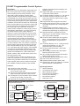
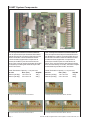
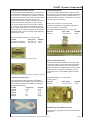
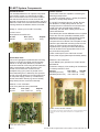
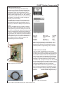
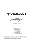
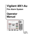
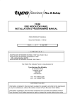
IO-NET
Programmable
Control
System.
A Product
Overview
FIRE & EVACUATION SYSTEMS
IO-NET Programmable Control System
Description
IO-NET is a low cost, distributed, field programmable control system that combines flexible control
with networking communication facilities. It handles small or large numbers of inputs and/or
outputs, whether concentrated at a single location
or distributed over a wide area. All inputs are multilevel and can therefore provide the line supervision
of input wiring often required for alarm applications.
In addition, the IO-NET Controller can receive high
level communications from a fire alarm system and
use that information as additional input conditions
for control logic. This combination of features
makes IO-NET suitable for a wide range of control
and telemetry applications: e.g. Alarm monitoring,
AS 1668 Fire Fan Control, Mimic display of
alarms, PLC with remote indication, Point-to-point
telemetry, Remote annunciation, Stand-alone PLC.
IO-NET uses a proprietary, token-passing bus
communication protocol that ensures efficient
network operation. Peer to peer communication is
easily achieved as no “master” station is required
to control network traffic. The network continues to
function quickly even when the volume of information to be transmitted is high. A 2 wire (data only)
or a 3 wire (data and power supply), multi-dropped
connection is the standard IO-NET system communications medium without special cables. Data
speeds are selectable from 1200 to 9600 baud.
RS485, modem, radio, and fibre optic communications may also be used.
An IO-NET System consists of at least one Controller. The Controller is connected to Termination
Boards using flat ribbon cable looms. If connection
to fire indicator panel communications is required
then a RZDU to RS232 interface is also needed.
Features
n 32 Inputs on each Controller.
n Each input common 0V, clean contacts, endof-line resistor supervised.
n Inputs (in programmed mode) are multi-level:
Open Circuit, Normal, Alarm, Short Circuit.
n 32 Outputs on each Controller. Open collector
closure to 0V: 30 volts, 100 mA max.
n High level link compatible with Vigilant fire
n
n
n
n
n
n
n
n
n
n
n
n
n
n
n
n
indicator panel Remote Zone Display Unit
(RZDU) protocol.
Supervised cable connection to Input and
Output Termination Boards.
Controller operating voltage 17.5 - 28 volts dc.
Controller current 6.5 mA plus 0.3 mA for
every open collector output turned on (plus
connected load).
Programmed and unprogrammed modes.
Readily programmed on-site or off-site using
a personal computer and a small programming unit.
Programmable parameters stored in nonvolatile PROM which can be reprogrammed
several times (depending on program size).
Data Transmission: multidrop line driver
switching 0 to 24 volts. RS485, modem and
fibre optic link also available.
Communication cable length: 3km @ 2400
baud, 1 km @ 9600 baud using multidrop
line driver transmission, longer with modems.
Controller address: 0 to 31 - unprogrammed
mode (32 Controllers). 0 to 127 - programmed mode (128 Controllers).
Communication baud rates: 1200, 2400,
4800, 9600.
16 & 32 Way Protected Input Termination
Boards (exclude FRC Loom).
16 & 32 Way Protected Output Termination
Boards (exclude FRC Loom).
16 Way Relay Board (includes FRC Loom).
FRC Looms from 0.25 to 5m.
Optional cabinet: 494W x 449H x 82D.
Optional gear plate, pre-drilled for Controller
and Termination or Relay Boards.
Typical Applications
√
Alarm monitoring,
√
AS 1668 Fire Fan Control,
√
Mimic display of alarms,
√
PLC with remote indication,
√
Point to point telemetry,
√
Remote annunciation,
√
Stand alone PLC
Some Examples of IO-NET Applications
Point to Point Telemetry
Programmable Controller
32 Inputs
IO-NET
Controller
32 Outputs
IO-NET
Controller
32 Ouputs, 32 Inputs
each Controller
Remote Mimic Panel
32 Ouputs &
32 Inputs
2 Wire
IO-NET
Controller
Vigilant RZDU
High Level Link
Page 2
IO-NET
Controller
IO-NET
Controller
Mimic
Outputs
as
required
32 per
Controller
IO-NET
Controller
IO-NET
Controller
32 Ouputs, 32 Inputs
each Controller
IO-NET
Controller
LT0185, IO-NET Programmable Control System, Product Overview, V1.0
IO-NET System Components
IO-NET Controller PA0498
IO-NET Controller
Each IO-NET Controller has 32 digital inputs and
can provide up to 32 programmable outputs. From
this starting point the system can be expanded up
to a maximum of 128 Controllers on one IO-NET
communications line (although physical constraints
may limit a system to less than this). At least 32
Controllers can be supported on a 1mm 2 line up to
3 km long.
Each Controller also supports a high level (Remote
Zone Display Unit) input link from a compatible
Vigilant fire alarm system. This makes the locally
connected fire alarm system zone states available
to the output logic of that Controller. In addition, the
data from the high level input link of up to eight
Controllers can be sent over the IO-NET system
and so made available to the output logic of all
other Controllers.
Without programming (apart for setting address
switches) up to 32 IO-NET Controllers can function
as a point to point telemetry system enabling the
status of individual inputs to be transferred to
outputs over a pair of wires. This means that for
this application up to 512 inputs at one point (16
Controllers) can be repeated as 512 outputs at a
second point, while at the same time 512 inputs at
the second point can be repeated at the first point.
Alternatively the Controllers could be distributed
throughout a site. In this case each Controller
would send its input state to, and receive its output
state from one other Controller. This
unprogrammed mode of operation is selected by a
dip-switch on each Controller.
Powerful programmable control may be achieved
on each IO-NET Controller by selecting the
programmed mode of operation. The conditions of
all remote, local and high level inputs in a system
are available to programmable Boolean logic
expressions. Logic expressions may include local
Timer status, Variables, Output Status, Controller
and Network Status as well as local and global
input status. Complex functions make operations
such as change-of-state annunciation, and others
possible. The logic expressions and parameters
for specific outputs, timers and variables are stored
in a nonvolatile, low-cost PROM on the corresponding IO-NET Controller. All Controllers in a
Programmed IO-NET System do not need to
operate in Programmed Mode. Controllers operating in Unprogrammed Mode can be used to gather
input conditions provided no outputs are used.
The IO-NET PROM programming process is
quickly accomplished either on-site or off-site using
a personal computer and a small programming
unit. The PROM is inserted into the programming
module. Logic equations are typed into the computer and saved as a text source file. A compiler
program, operating on the PC, generates the
program file and downloads it into the PROM. If
program size permits, each PROM may be reprogrammed several times before it becomes full and
must be replaced.
To assist with IO-NET system setup and trouble
shooting, a diagnostics program is provided with
the IO-NET programming unit and compiler. This
enables the system data to be viewed on a personal computer.
The IO-NET Controller is a single printed circuit
board. Demountable terminals for the power supply
connection (24 volts dc) and the serial data
communications are located at one end of the
board. Input and output plug-in connectors are
located on each side of the board. These must be
connected to separate termination boards using
flat ribbon cable looms.
Part No
PA0498
LT0185, IO-NET Programmable Control System, Product Overview, V1.0
Dim. (mm)
270 x 165 x 25
Ship Wt
310 g.
Page 3
IO-NET System Components
32 Input Protected Termination Board
Controller
16 Way Relay Board
16 & 32 Input Protected Termination Boards
The 16 Input and 32 Input Protected Termination
Boards are used for connecting field wiring to the
IO-NET Controller. These termination boards
include transient suppression components to
protect the IO-NET inputs from electrical transients. They must be used to terminate all IO-NET
Controller input cabling that extends beyond the
IO-NET enclosure.
16 & 32 Output Protected Termination Boards
The 16 Output and 32 Output Protected Termination Boards are used for connecting field wiring to
the IO-NET Controller. These termination boards
include transient suppression components to
protect the IO-NET inputs from electrical transients. They must be used to terminate all cabling
that connects directly to IO-NET Controller outputs
and extends beyond the IO-NET enclosure.
Cable Termination Capacity: 1.5 sq mm max.
Part No
Dim. (mm)
Ship Wt
PA0479 (16 Way) 135 x 93 x 23
100 g.
PA0474 (32 Way) 270 x 93 x 23
200 g.
Cable Termination Capacity: 1.5 sq mm max.
Part No
Dim. (mm)
Ship Wt
PA0480 (16 Way) 135 x 93 x 23
100 g.
PA0475 (32 Way) 270 x 93 x 23
200 g.
16 Input Protected Termination Board, PA0479
16 Output Protected Termination Board, PA0480
32 Input Protected Termination Board, PA0474
32 Output Protected Termination Board, PA0475
Page 4
LT0185, IO-NET Programmable Control System, Product Overview, V1.0
IO-NET System Components
Unprotected Termination Boards
Unprotected Termination Boards are small printed
circuit boards providing direct screw terminations
for 16 inputs or 16 outputs of an IO-NET Controller.
No transient protection is provided so these boards
should only be used where the wiring is not
extended beyond the IO-NET Controller enclosure.
Typical uses include connection of mimic lamps
and control panel switches to an IO-NET Controller. A version of this board is available for connection to LEDs without their own current limiting. The
current limiting 3k3 series resistors set the current
to approximately 7 mA from 24Vdc. High efficiency
LEDs must be used.
16 Way Relay Board
The 16 Way Relay Board has the same physical
dimensions and footprint as the 32 Way Protected
Termination Board. It comes complete with a 1.4
metre flat ribbon cable for connection to one of the
IO-NET output connectors.
Relay Coil Current: 12 mA at 24 volts.
Contact Configuration: Single pole changeover.
30V, 2A resistive, 1A inductive.
Cable Termination Capacity: 1.5 sq mm max.
Part No
Dim. (mm)
Ship Wt
PA0470
270 x 93 x 25
350 g.
Cable Termination Capacity: 1.5 sq mm max.
Part No
Dim. (mm)
Ship Wt
PA0483 (no resistors)
69 x 46 x 18 100 g.
PA0769 (c/w resistors)
69 x 46 x 18 100 g.
16 Way Relay Board, PA0470
16 Way Unprotected Termination Board, PA0483
RZDU to RS232 Interface
The RZDU to RS232 Interface is a small printed
circuit board that converts Remote Zone Display
Unit serial communications from a fire indicator
panel into RS232 compatible signals. This module
is required for an IO-NET Controller to receive
information from a compatible Vigilant fire alarm
panel.
16 Way Unprotected Termination Board c/w Resistors, PA0769
Termination Board Looms
Each termination board requires a Flat Ribbon
Cable (FRC) loom to enable it to be connected to
the Controller. Looms are available in a variety of
lengths as listed below.
Part No
Length (m)
Ship Wt
LM0049
0.25
20 g.
LM0046
0.5
30 g.
LM0056
1.4
70 g.
LM0044
2.0
95 g.
LM0045
5.0
220 g.
Operating Voltage: 17 to 30 volts dc.
Current: 5 mA.
Part No
Dim. (mm)
PA0481
104 x 72 x 23
Ship Wt
100 g.
RZDU to RS232 Interface, PA0481
RS485/ Fibre Optic/Radio Interface
This uses non-proprietary items therefore consult
distributor.
Loom, 0.5 metre FRC, LM0046
LT0185, IO-NET Programmable Control System, Product Overview, V1.0
Page 5
IO-NET System Components
1200 Baud Modem
The 1200 Baud Modem is an optional component
of an IO-NET system. It is required for IO-NET
data communications over non-metallic media or
over telecommunications circuits where Austel
approval is required or for communication over long
distances. Refer to the User Manual for the details
of wiring between the Modem and the Controller.
Voltage: 5 volts dc (from IO-NET Controller)
Current: 15 mA
Austel permit A94/37D/0100
Part No
Dim. (mm)
Ship Wt
PA0464
130 x 49 x 23
100 g.
1200 Baud Modem, PA0464
IO-NET Gear Plate
The IO-NET gearplate is predrilled with mounting
holes for an IO-NET Controller and Termination
Boards or 16 Way Relay Boards. It provides a
convenient method of mounting IO-NET hardware
within a rack cabinet or other enclosure. The
printed circuit boards are mounted on the
grearplate using nylon push-on printed circuit
board standoffs (part no HW0130). The space at
the top of the gear plate has mounting holes for a
24 volt power supply (FP0474), or alternatively
another termination board (e.g. second 16 Way
Relay Board) can be mounted horizontally.
IO-NET Cabinet
The IO-NET Cabinet is capable of containing the
following arrangements:
1 x IO-NET Controller plus 3 x 32 Way Termination
Boards or 16 Way Relay Boards
2 x IO-NET Controllers plus 5 x 32 Way Termination Boards or 16 Way Relay Boards. For this
arrangement the Controllers are mounted on the
inside of the door with adhesive standoffs
(HW0208), with flat ribbon cabling across to the
Termination Boards.
The cabinet part number ME0088 comes complete
with a 003 cam lock (Australian standard) while
ME0089 has a 60124 lock (NZ standard). A gear
plate is not necessary for mounting IO-NET
components in this cabinet. The back plate of each
cabinet is pre-drilled with mounting holes to suit a
variety of PCB mounting arrangements and is
supplied with a quantity of loose PCB standoffs
that can be fitted in the appropriate holes to suit
the particular arrangement.
There is also space in the cabinet for a small
mains power supply (PA0736) and standby battery.
Material: 1.0mm mild steel.
Finish: Baked epoxy powdercoat, Cream Wrinkle
BFF998CW.
Protection Category: IP50; sealing can be added to
increase protection to IP51.
Part No
Dim. (mm)
Ship Wt
ME0088 (003 lock)
494 x 449 x 82 4.8 kg.
ME0089 (60124 lock) 494 x 449 x 82 4.8 kg.
Material: 1.6 mm mild steel.
Finish: Zinc plated & colour passivated.
Part No
Dim. (mm)
Ship Wt
FA1185
430 x 450 x 10
2.3 kg.
IO-NET Cabinet, ME0088 / ME0089
(Cabinet shown with Controller, 16 Way Relay Board, 16 Way Output Board, 32 Way
Input Board, and Power Supply fitted. These items are not supplied with the
Cabinet.)
IO-NET Gear Plate, FA1185
Page 6
LT0185, IO-NET Programmable Control System, Product Overview, V1.0
IO-NET System Components
IO-NET Programming Unit
The IO-NET Programming Unit transfers the
program to the IO-NET Controller PROMs. This
process is required for a controller to operate in
programmed mode. The Programming Unit is
supplied complete with a cable to connect between
the PC and the Programming Unit, the compiler
programming software (for a PC), and the IO-NET
User Manual. An external 24 volts dc supply is
required (19.2 to 28.3 volts).
Complete instructions on how to program an IONET PROM are contained in the IO-NET User
Manual and this should be read before any programming is carried out. Briefly the process is as
follows:
Remove the PROM from the IO-NET Controller
and insert it into the Programming Unit. Connect
the Programming Unit to the serial port of the PC
and to the 24 volts power supply. Generate (or edit)
a text file containing the required logic equations
on the PC, compile the text file using the programming software, then download it into the PROM in
the Programming Unit. Turn off the power supply to
the Programming Unit, remove the PROM and
insert it back into the IO-NET Controller. The
programming process is complete.
IO-NET Programming Unit, PA0700
Programming Lead, LM0041
IO-NET Complier, SF0088
LT0115, IO-NET User
Part No
Dim. (mm)
Ship Wt
PA0700
180 x 240 x 50
700 g.
LM0041
2,000
80 g.
SF0088
90 x 94 x 3
20 g.
LT0115
230 x 325 x 7
450 g.
Note: The Programming Lead (LM0041), the IONET Compiler (SF0088) and the IO-NET User
Manual (LT0115) are all included when Part No
PA0700 (IO-NET Programming Unit) is ordered.
IO-NET Controller PROM
This is a “blank” replacement microprocessor
PROM for the IO-NET Controller. It comes already
for use in the non-programmed mode operation of
the IO-NET Controller, and has completely blank
user program space for operation in programmed
mode. A standard Controller PROM (part number
SF0087) is supplied inserted into each IO-NET
Controller, and, if program size permits, this PROM
may be reprogrammed a number of times. Eventually the user program space will become full and a
replacement PROM must then be obtained.
For applications where the program size is larger
than normal, a PROM with more RAM and over 5
times more program storage capacity is available.
SF0087
IO-NET PROM, Standard memory
SF0139
IO-NET PROM, Larger memory
SF0087 IO-NET Controller PROM
LT0185, IO-NET Programmable Control System, Product Overview, V1.0
Page 7
IO-NET System Components
Other Products
Some of the other products that can be used with
IO-NET are listed below.
Modbus Bridge: The Modbus Bridge is used to
interface an IO-NET system with a Building
Management System or other third party monitoring system. It makes the input status of all IO-NET
Controllers and the zone status of any connected
fire alarm panels available in the widely supported
Modbus communications protocol.
Part No
Dim. (mm)
Ship Wt
FP0675
450 x 280 x 80
5.5 kg.
Picture Frame Display Cabinet: This is a low
profile, metal cabinet with a lockable, front opening
door. The door is covered by a translucent acrylic
panel, making it an ideal enclosure for wall
mounted mimic and/or control panels. Internal
mounting arrangements are provided for up to four
Mimic Display Boards and up to two IO-NET
Controllers.
Part No
Dim. (mm)
Ship Wt
ME0073
550 x 440 x 58
5 kg.
Mimic Display Board: The Mimic Display Board
contains 16 red LEDs positioned in line at 12.7 mm
centres to provide index lamps for a mimic panel.
Two versions of the board are available. PA0753
has 5mm LEDs that extend 25 mm so as to
protrude through the acrylic door panel of the
Picture Frame Display. PA0738 has shorter 3 mm
LEDs and mounts behind a mimic panel with the
LEDs visible through holes in the panel. Both PCBs
connect directly to the output connectors on the
IO-NET Controller via standard flat ribbon cables.
Part No
Dim. (mm)
Ship Wt
PA0738
248 x 98 x 16
100 g.
PA0753
248 x 98 x 28
100 g.
IO-NET is a product of:
Vigilant Fire & Evacuation Systems
211 Maces Road, Bromley
Box 19-545
Christchurch 8006
New Zealand
System Part Numbers
FP0474 Power Supply, 24V, 2.5A
FP0675 Modbus Bridge
FA1185 IO-NET Gearplate
HW0130 PCB Standoff, 6.25 mm mounting
HW0208 PCB Standoff, adhesive base
LM0041 Programming Lead (included in PA0700)
LM0044 Loom, 2 metres
LM0045 Loom, 5 metres
LM0046 Loom. 0.5 metres
LM0049 Loom, 0.25 metres
LM0056 Loom, 1.4 metres
LT0115 IO-NET User Manual (included in PA0700)
ME0073 Picture Frame Display Cabinet
ME0088 IO-NET Cabinet (003 Lock)
ME0089 IO-NET Cabinet (60124 Lock)
PA0464 1200 Baud Modem
PA0470 16 Way Relay Board
PA0474 32 Input Protected Termination Board
PA0475 32 Output Protected Termination Board
PA0479 16 Input Protected Termination Board
PA0480 16 Output Protected Termination Board
PA0481 RZDU to RS232 Interface
PA0483 16 Way Unprotected Termination Board
PA0498 IO-NET Controller
PA0700 IO-NET Programming Unit
PA0736 Power Supply, 24V, 0.5A
PA0738 Mimic Display Board (3mm LEDs)
PA0753 Mimic Display Board (5mm LEDs)
PA0769 16 Way Unprot. Term. Bd c/w Resistors
SF0087 IO-NET Controller PROM (standard)
SF0088 IO-NET Compiler (included in PA0700)
SF0139 IO-NET Controller PROM (large mem.)
IO-NET is also available from:
Distributed in Australia by:
Grinnell Detection Products
16-18 Shearson Crescent
Mentone VIC 3194
Telephone: (03) 9584 2544
Fax: (03) 9584 6134
Page 8
LT0185, IO-NET Programmable Control System, Product Overview, V1.0