1
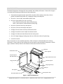
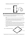
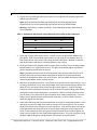
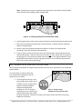
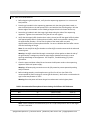
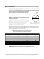
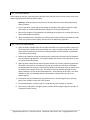
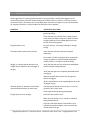
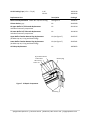
OPERATING MANUAL Model S2® #21105036 Sequencing Gel Electrophoresis Apparatus Apogee Electrophoresis | 101 Kane Street | Baltimore, MD 21224 USA | apogeephoresis.com Apogee Electrophoresis | 101 Kane Street | Baltimore, MD 21224 USA | apogeephoresis.com S2 SEQUENCING APPARATUS OPERATING MANUAL - TABLE OF CONTENTS Before You Begin 1.0 Important Information 1.1 Safety Warnings 1.2 Components 1.3 Operating Instructions Gel Casting 2.0 2.1 Preparation of Glass Plates Using Gel Sealing Tape 2.1.1 Preparation of Glass Plates Using the S2 Casting Clamp 2.1.2 Pouring the Gel Using Gel Sealing Tape 2.1.3 Pouring the Gel Using the S2 Casting Clamp 2.1.4 Electrophoresis 2.2 Pre-electrophoresis 2.2.1 Loading Samples 2.2.2 Electrophoresis 2.2.3 Post-Electrophoresis 2.2.4 Troubleshooting Guide 3.0 References 4.0 Related Products and Replacement Parts 5.0 Care and Handling 6.0 Materials and Care 6.1 General Specifications 6.2 Technical Support and Service 6.3 Instructions for Return Shipment 6.4 Cleaning and Decontamination for Return Shipment 6.4.1 Notice Regarding the Return of Apparatus Products 6.4.2 Warranty 7.0 Warranty 7.1 Declaration of Conformity and CE Mark 7.2 Decontamination Declaration 8.0 Apogee Electrophoresis | 101 Kane Street | Baltimore, MD 21224 USA | apogeephoresis.com FIGURES 1. S2 Gel Electrophoresis Apparatus Components 2. Taping Glass Plates 3. Assembly Using S2 Casting Clamp 4. Gel Casting Configuration of Sharkstooth Comb 5. Sample Loading Configuration of a Sharkstooth Comb 6. Sharkstooth Comb Sample Loading Technique 7. S2 Repair Components TABLES 1. Approximate Gel Solution Volume Requirement for Different Gel Thicknesses 2. Recommended Electrophoresis Power Settings for Different Gel Thicknesses 3. Sample Loading Volumes for Model S2 Apparatus Square-Toothed Combs as a Function of Gel Thickness MODEL S2® is a registered trademark of Apogee Designs, Ltd. DELRIN® and MYLAR® are registered trademarks of E.I. DuPont de Nemours & Co. Tygon® is a registered trademark of Norton Company. Apogee Electrophoresis | 101 Kane Street | Baltimore, MD 21224 USA | apogeephoresis.com 1.0 BEFORE YOU BEGIN 1.1 IMPORTANT INFORMATION The Model S2® Sequencing Gel Electrophoresis Apparatus is authorized for laboratory research use only. It has not been qualified for use in any human or animal diagnostic or therapeutic application. Use for other than the intended use may be a violation of applicable law. The Model S2 is designed for vertical polyacrylamide gel separations of the products of dideoxy and chemical sequencing reactions. The system is useful for preparative purifications of oligonucleotides, DNA foot printing procedures, ribonuclease protection assays, and sequence determinations of up to 250 to 350 bases. This manual provides operating instructions for the Model S2 Apparatus. If the product is used in a manner not specified by Apogee, the protection provided by safety features of the product may be impaired. Please carefully follow the manual’s instructions. Do not alter equipment or operate with broken components. Failure to adhere to these directions could result in personal and/or laboratory hazards as well as invalidate the equipment warranty. 1.2 SAFETY WARNINGS DANGER! HIGH VOLTAGE! This system requires a 1,000 to 3,000 VDC power supply for operation and is, therefore, a source of high voltage. The power supply should have earth/ground leakage protection and open-circuit sensing. Although equipped with a safety interlock system, this equipment must always be operated with extreme caution. Careless handling can result in possibly fatal electrical shock. This apparatus should always be operated with caution. Careless handling can result in electrical shock. The system should be operated by trained personnel only. Certain reagents indicated for use in this manual are of a hazardous nature. The researcher is cautioned to exercise care when handling these reagents. Equipment used in these procedures (e.g., high voltage power supplies) should be used following the manufacturer’s safety recommendations. Always follow the power supply manufacturer’s recommendations for use and follow safety procedures. Never operate damaged or leaking equipment. Inspect the apparatus, electrical connections and power cords prior to use. For maximum safety, always operate this system in an isolated, low-traffic area, not accessible to unauthorized personnel. Before applying DC power to this equipment, make sure that all electrical connections are secure and that power cords show no signs of damage. Always turn off the DC power source before disconnecting DC power cords from the sequencing apparatus. Disconnect power cords from the power source first, and then from the apparatus. Apogee Electrophoresis | 101 Kane Street | Baltimore, MD 21224 USA | apogeephoresis.com 1.3 COMPONENTS The Model S2 Apparatus is designed for easy assembly and reliable performance. Please refer to Figure 1 to identify the following principal features and components: Electrophoresis apparatus with upper buffer chamber, buffer chamber drain valve, silicone gasket, removable lower buffer tray, integral gel clamps, and safety lids One pair of 122 cm (48”) red and black power cords One pair of glass plates (one short, one long) Long – 333 mm (13.12”) wide x 419 mm (16.50”) long Short – 333 mm (13.12”) wide x 394 mm (15.50”) long One pair of 0.40 mm thick vinyl side spacers One pair of 0.35 mm thick Mylar side spacers Package of four 0.40 mm thick vinyl sharkstooth combs Package of two 0.35 mm thick Mylar sharkstooth combs Package of 12 adhesive-backed foam blocks for side spacers One roll of high voltage gel sealing tape, 38 mm (1.50”) wide x 66 m (72 yards) long Instruction manual Many components are also available separately. Refer to Chapter 5, Related Products for ordering information. Please read all of the following instructions before using the Model S2 Apparatus. Review Figure 1 below to identify features and components discussed in these instructions. Safety lid Sharkstooth combs Silicone gasket Vinyl side spacer with foam block Upper buffer drain valve Long glass plate Short glass plate Aluminum plate Integral gel clamps Safety lid Gel supports DC HV power cords Removable buffer tray Figure 1. Model S2 Components Apogee Electrophoresis | 101 Kane Street | Baltimore, MD 21224 USA | apogeephoresis.com 2.0 OPERATING INSTRUCTIONS This chapter provides operating instructions for the Model S2 Apparatus. For a list of references containing formulations of buffers and acrylamide solutions, as well as other applications information for polyacrylamide gel sequencing and fragment purification, see Chapter 4, References. 2.1 GEL CASTING Gels can be cast after assembling the glass plates and spacers using Gel Sealing Tape or the S2 Casting Clamp. These techniques are appropriate for casting polyacrylamide gels. 2.1.1 PREPARATION OF GLASS PLATES USING GEL SEALING TAPE 1. Select a pair of glass plates (one long, one short). Be sure that the edges to be sealed with tape are free of nicks or chips. 2. Clean the glass plates thoroughly with a nonabrasive detergent and a plastic scouring pad. The cleaning solution should not leave a soap residue when rinsed thoroughly. Avoid scratching the surface of the glass plates. Note: Never use steel wool to scrub the glass plates. 3. Rinse the glass plates thoroughly with deionized water and wipe dry. 4. If desired, treat the inside (acrylamide contact) surface of one or both glass plates (usually the short plate) with a siliconizing reagent, following the manufacturer’s instructions. 5. Immediately before assembling the glass plate ‘sandwich’, rinse the inside surfaces with ethanol and wipe them dry with a lint-free paper towel. Avoid touching the inside surfaces with your fingers. 6. Assemble the glass plate sandwich in the conventional manner: place the long glass plate inside-up on the bench, align the vinyl side spacers at the sides, and place the short glass plate inside-down on the side spacers. Make sure that the foam blocks at the tops of the side spacers are snug against the top of the short glass plate and that the ends of the side spacers are 4 to 7 mm short of the bottom of the assembled plate sandwich. Note: Before using vinyl side spacers for the first time, attach a foam block at one end of each spacer. Remove the protective backing from the adhesive side of a foam block, align the end of the block with the end of the side spacer, and press the block firmly into place. Foam blocks may be replaced, as needed, using the extras provided with the Model S2 Apparatus. 7. Seal the sides and bottom of the assembled glass plate sandwich with gel sealing tape, as shown in Figure 2. Tape the sides first (a, b) and then the bottom (c). Extend the tape around the bottom corners in both directions to ensure an adequate seal. Apply the tape as smoothly as possible to avoid forming air channels or bubbles along the edges of the glass plates. Rub the tape firmly onto glass to eliminate air channels and ensure a liquid-tight seal. 8. Place two accessory spring clips (available separately) along each side near the middle and bottom of the glass plate sandwich. This will help maintain uniform gel thickness while Apogee Electrophoresis | 101 Kane Street | Baltimore, MD 21224 USA | apogeephoresis.com pouring the gel. It is important for the spring clips to be placed over the side spacers only. Clamping unsupported glass will distort the thickness of the gel. Figure 2. Taping Glass Plates 2.1.2 PREPARATION OF GLASS PLATES USING THE S2 CASTING CLAMP The S2 Casting Clamp can be used in place of the gel sealing tape and spring clips to seal the edges of the glass plates while casting the gel. Assemble the glass plates as before, and place the assembled sandwich in the casting clamp following the instructions below. 1. Make sure that the inner surface of the casting clamp is clean of all dried acrylamide and grease. 2. Hold the casting clamp vertically with your thumbs resting at the top of the molded handles and your index fingers over the molded feet, flex the clamp outward in a bow-like manner so that the bottom of the clamp can fit onto the bottom of the gel sandwich. 3. Fit the gel sandwich snugly into the bottom of the casting clamp. Start at one corner and seal towards the other corner. 4. After the gel sandwich is seated into the bottom of the clamp, fit the sides of the clamp onto the sides of the gel sandwich. Start at the bottom of one side, using your hands to smooth the clamp onto the gel sandwich. Repeat this for the other side of the gel sandwich. 5. When properly placed, the sides of the casting clamp will extend to within 4-5-mm of the top of the short glass plate (See Figure 3). If the sides of the clamp should extend further than this, reposition the sides of the casting clamp so that they are at the top of the short glass plate. Glass plates Figure 3. Assembly using S2 Casting Clamp Casting clamp Apogee Electrophoresis | 101 Kane Street | Baltimore, MD 21224 USA | apogeephoresis.com 2.1.3 POURING THE GEL USING GEL SEALING TAPE 1. Prepare the acrylamide gel solution (see Table 1 for the approximate volumes required for different gel thicknesses). Note: Most gel formulations allow approximately 10 min before polymerization. Polymerization time can be extended by reducing the amount of TEMED added. Warning: Acrylamide is a known neurotoxin. Consult the Material Safety Data Sheet for more information. Table 1. Approximate Gel Solution Volume Requirement for Different Gel Thicknesses. Gel Thickness (mm) 0.2 0.4 0.8 1.6 Wedge (0.4 to 1.2 mm thick) Volume Required (ml) 35 65 130 260 140 2. Use a large syringe, squirt bottle, funnel, or beaker to pour the gel solution between the glass plates. Hold the assembled plate sandwich at a 45° angle on one bottom corner so that the gel solution flows evenly down along the lower side spacer. Maintain a constant, even flow to reduce the chance of forming bubbles in the solution. 3. As the gel sandwich fills, gradually lower the glass plates until they rest on the bottom edge, approximately at a 5° angle from the bench. The gel mold should be slightly overfilled to ensure complete polymerization at the top. Note: If a bubble forms while the gel is being poured, raise the glass plates into a vertical position, and either tip the gel solution away from the bubble or carefully tap the plate sandwich at the bubble to make it rise to the surface. Once all bubbles have been removed, return the glass plates to their previous position. 4. Before the acrylamide polymerizes, insert a well-forming comb into the top of the gel. If you are using a sharkstooth comb, insert the flat edge of the comb between the glass plates to a depth of 2 to 3 mm below the top of the short glass plate (Figure 4). Keep the flat edge shallow to simplify subsequent reinsertion of the comb in the sample loading (teeth-down) configuration and to allow loading with a micropipette. Mark one end of the comb so that you can keep it in the same left-to-right orientation when loading samples later. If you are using a DELRIN® square-toothed comb (available separately), insert the teeth 4 to 5 mm below the edge of the short plate. 5. A top clamp and spring clips are recommended for securing the comb/plate sandwich. Place two spring clips over the edge of the plates to clamp on the comb (Figure 4). Do not place the pressure points of the spring clip over the side spacer. Place the top clamp over the top of the glass plates and clamp the center of the top edges of the plate securely against the comb. Proper placement of the spring clips and top clamp will force the plates against the comb, ensuring a tight fit of the comb following polymerization. If you use spring clips along the lower edge of the gel for sealing purposes, clamp them on the side spacers. Apogee Electrophoresis | 101 Kane Street | Baltimore, MD 21224 USA | apogeephoresis.com Note: If spring clips are not put in place during polymerization, the comb will not fit tightly, which increases the possibility of leaks between wells. Figure 4. Gel Casting Configuration of Sharkstooth Comb 6. Leave the glass plates in their near-horizontal position until the acrylamide has polymerized. 7. Remove the spring clips (and top clamp, if used) and tape. Carefully slide the comb from between the glass plates. 8. Rinse the top of the gel with electrophoresis buffer to remove any unpolymerized acrylamide. Rinse the comb with deionized water. 9. If you are using a sharkstooth comb, reinsert the comb between the glass plates with the teeth toward the gel. Insert the comb until the teeth just make contact with the surface of the gel (figure 5). Do not allow the teeth to pierce the gel. A very slight indentation of the gel should be visible when the comb is properly inserted. Do not slide the comb laterally after it has come in contact with the gel. 2.1.4 POURING THE GEL USING THE S2 CASTING CLAMP The S2 Casting Clamp allows for the gel to be filled from either the top or the bottom of the assembled plate sandwich. To cast the gel from the top, follow the instructions below making sure that the bottom fill port is sealed. 1. To fill the gel from the top, use a large syringe, squirt bottle, funnel, or beaker to pour the gel solution between the plate sandwich. Hold the assembled plate sandwich at a 25°-35° angle on Figure 5. Sample Loading one bottom corner so that the gel Configuration of Sharkstooth Comb solution flows evenly down along the lower side spacer. Maintain a constant, even flow to reduce the chance of forming bubbles in the solution. Apogee Electrophoresis | 101 Kane Street | Baltimore, MD 21224 USA | apogeephoresis.com 2. As the gel sandwich fills, gradually lower the casting clamp until it rests on the molded feet, approximately a 5° angle. The gel mold should be slightly overfilled to ensure complete polymerization at the top. 3. Before the acrylamide polymerizes, insert a well-forming comb into the top of the gel. If you are using a sharkstooth comb, insert the flat edge of the comb between the glass plates to a depth of 2 to 3 mm below the top of the short glass plate (Figure 4). Keep the flat edge shallow to simplify subsequent reinsertion of the comb in the sample loading (teeth-down) configuration and to allow loading with a micropipette. Mark one end of the comb so that you can keep it in the same left-to-right orientation when loading samples later. If you are using a DELRIN® square-toothed comb (available separately), insert the teeth 4 to 5 mm below the edge of the short plate. 4. For improved comb sealing, clamp the glass plate sandwich over the comb with a top clamp over the center of the comb. It is important for the top clamp to be placed over the comb only. Clamping unsupported glass will distort the thickness of the gel. The casting clamp does not require the use of accessory spring clips along the sides of the gel sandwich. 5. Leave the glass plates in their near-horizontal position until the acrylamide has polymerized. 6. Remove the top clamp (if used) and carefully slide the comb from between the glass plates. 7. Remove the glass plates from the casting clamp. Pull the casting clamp off the glass plates starting at the top and working your way down. Take care in that there may be some unpolymerized acrylamide in the bottom of the casting clamp. 8. Rinse the top of the gel with electrophoresis buffer to remove any unpolymerized acrylamide. Rinse the comb with deionized water. 9. If you are using a sharkstooth comb, reinsert the comb between the glass plates with the teeth toward the gel. Insert the comb until the teeth just make contact with the surface of the gel (Figure 5). Do not allow the teeth to pierce the gel. A very slight indentation of the gel should be visible when the comb is properly inserted. Do not slide the comb laterally after it has come in contact with the gel. To fill the gel from the bottom, assemble the gel plates so that when the casting clamp is laying down on the molded feet, the short glass plate is on top. 1. Place the assembled gel sandwich on a level surface resting on the molded feet of the casting clamp. 2. Open the bottom fill port and insert a Luer fitting. 3. Attach a syringe of suitable reservoir to the fitting and slowly fill the gel. Do not interrupt the filling as this may introduce bubbles into the gel solution. 4. Once the gel is filled, insert the comb as before and allow the gel to polymerize. Apogee Electrophoresis | 101 Kane Street | Baltimore, MD 21224 USA | apogeephoresis.com 2.2 ELECTROPHORESIS 2.2.1 PRE-ELECTROPHORESIS 1. Before beginning electrophoresis, verify that the sequencing apparatus is in a secure and level position. 2. Place the gel sandwich in the sequencing apparatus with the short glass plate inward, so that the foam blocks on the side spacers form a seal with the blue silicone gasket. Rest the bottom edge of the sandwich on the ribbed gel support blocks in the lower buffer tray. 3. Secure the gel sandwich with the integral gel clamps along the sides of the sequencing apparatus. Tighten the screw knobs firmly, but do not over tighten. 4. Verify that the upper buffer chamber drain valve is closed, and fill the upper buffer chamber with approximately 450 ml of electrophoresis buffer. Make sure no buffer is leaking from the upper buffer chamber. Fill the front chamber of the lower buffer tray with approximately 450 ml of electrophoresis buffer. Be sure no bubbles obstruct buffer contact with the lower edge of the gel. Note: Do not overfill the buffer chambers or allow buffer to make contact with the electrode mounting nuts. Warning: No buffer should leak through or around the silicone gasket or down the side of the gel assembly. Leakage may allow the upper buffer chamber to drain dry or cause sparking and damage to the apparatus. See Chapter 3, Troubleshooting, for further information. 5. Close the upper and lower safety lids and connect the DC power cords to the sequencing apparatus and the DC power supply. Warning: All banana plug connections must be fully seated to prevent potential sparking and fire hazards. 6. Before loading samples, pre-electrophorese a gel for 15 to 45 min (see Table 2 for recommended DC power settings for various gel thicknesses). Best results are achieved with a gel surface temperature of ~50°C. Warning: Excessive power will cause the gel to overheat and crack the glass plates. Table 2. Recommended Electrophoresis Power Settings for Different Gel Thicknesses Gel Thickness (mm) 0.2 0.4 0.8 1.6 Wedge Watts (W=V x A) 55 60 65 70 85 to 90 Volts (V) 2,200 to 2,600 1,500 to 1,900 1,100 to 1,200 600 to 700 1,200 Current (mA) 20 to 35 30 to 45 60 to 90 95 to 125 ~70 Note: Power conditions were determined for a 50°C surface temperature with 1x TBE buffer. ~0.4 to 1.2 mm thick. Apogee Electrophoresis | 101 Kane Street | Baltimore, MD 21224 USA | apogeephoresis.com 2.2.2 LOADING SAMPLES 1. Prepare the samples by heating in an appropriate loading buffer to a temperature of 90°C to 100°C for 3 to 5 min and then chilling on ice. 2. At the end of the pre-electrophoresis period, turn off the power supply and disconnect both DC power cords, first from the power supply and then from the sequencing apparatus, before opening the upper safety lid. 3. Immediately prior to loading the samples, rinse the wells of the gel with electrophoresis buffer. Use a Pasteur pipette to wash away urea that has diffused into the wells. Note: Not rinsing the wells will prevent samples from layering properly on the gel surface. 4. Using a sharkstooth comb to form shallow wells (see Section 2.1.3) allows you to load samples with a micropipette or a drawn-out capillary pipette (Figure 6). When using the sharkstooth comb Figure 6. Sharkstooth Comb provided with the Model S2 Apparatus, load 2 to 3 µl of Sample Loading Technique sample per well. When using accessory double-fine sharkstooth combs, load 1.5 to 2 µl of sample. 5. When using optional square-toothed combs, load samples onto the bottom of the wells with capillary pipettes. To determine the sample loading volumes of Model S2 Apparatus squaretoothed combs relative to gel thickness, see Table 3. Table 3. Sample Loading Volumes f or Model S2 Apparatus Square-Toothed Combs as a Function of Gel Thickness Number of Teeth 16 Tooth Width (mm) 14.6 20 11.1 32 5.7 Gel Thickness (mm) 0.4 0.8 1.6 0.4 0.8 1.6 0.4 0.8 1.6 Capacity/Well (ul) 25 50 100 19 38 76 10 20 40 Note: All loading volumes are calculated for a comb insertion depth of 5 mm. Apogee Electrophoresis | 101 Kane Street | Baltimore, MD 21224 USA | apogeephoresis.com 2.2.3 ELECTROPHORESIS After loading the samples, close the upper and lower safety lids and connect the DC power cords to the sequencing apparatus and the DC power supply. Warning: All banana plug connections must be fully seated to prevent potential sparking and fire hazards. 1. Turn on the power supply and set the voltage or wattage to the proper setting for the gel (see Table 2 for recommended DC power settings for various gel thicknesses). 2. Monitor the progress of electrophoresis by following the migration of a marker dye front or by any other preferred method. 3. When electrophoresis is complete, turn off the power supply and disconnect both DC power cords, first from the power supply, and then from the sequencing apparatus. 2.2.4 POST-ELECTROPHORESIS 1. Open the buffer chamber drain valve to allow the buffer in the upper chamber to drain into the covered rear chamber of the lower buffer tray. Open the upper safety lid and rinse the upper buffer chamber with 25 to 50 ml of deionized water to prevent buffer crystallization in the internal drain tubing. 2. Release the integral gel clamps by loosening the screw knobs and remove the gel sandwich from the sequencing apparatus. Lay the gel sandwich flat, with the short glass plate on top, on a piece of absorbent paper. 3. Open the lower safety lid and remove the lower buffer tray from the sequencing apparatus. The buffer in the open front chamber of the tray will contain any radioactive nucleotides electrophoresed out of the gel. Dispose of this liquid by pouring away from the drain hole in the covered rear chamber of the tray. The buffer in the rear chamber (drained from the upper chamber) may then be discarded separately. After disposing of all buffer, rinse both chambers of the tray thoroughly with deionized water and place the tray back in the sequencing unit. 4. Disassemble the gel sandwich by prying off the short (or siliconized) glass plate, working gently from a bottom corner with a thin spatula. 5. For autoradiography, transfer the gel to a solid backing, such as paper or used film. 6. Rinse combs, side spacers, and glass plates to remove buffer and gel fragments, and dry all components before storing. Apogee Electrophoresis | 101 Kane Street | Baltimore, MD 21224 USA | apogeephoresis.com 3.0 TROUBLESHOOTING GUIDE Some suggestions for resolving common problems are given below. Should these suggestions not resolve the problem, please call Technical Support (see Section 6.3 for numbers). If the unit must be returned for repair, also contact our service department, the technical support or your local distributor for shipping instructions. Please include a full description of the problem. PROBLEM Gel Solution leaks from the bottom SUGGESTED SOLUTION Lower the angle of the glass plates when pouring the gel during casting. Check that the inner surface of the casting clamp is clean and free of debris and grease. Make sure that the glass plates are firmly seated against the inner surface of the casting clamp. The glass plates crack The gel is too hot. Use a lower wattage or voltage setting. The upper buffer chamber will not drain Check that the valve knob has been released sufficiently. Force water or buffer through the drain outlet with a syringe or pipette to remove possible dried buffer residue, airlock, or collapse in the drain tubing. ‘Wiggly’ or ‘slanting’ bands (bands are not straight lines or parallel to the top edges of the gel). Verify that the wells are free of particles and bubbles before and after loading samples. Verify that the agarose is completely dissolved before casting gels. Remove any particulate matter from the agarose before casting gels. Be sure that bubbles are not trapped against the comb during gel casting. All bands appear as ‘doublets’ (each band is represented twice within the same lane). Concentrate the sample and use a thin (2 to 3 mm) gel with a thin (1 mm) comb. Prevent gel movement during photography. The gel dye front is not straight Verify that the system is level. Make sure the system is not in a draft or otherwise being cooled unevenly. Verify that the buffer depth in both buffer trays is sufficient to provide complete, even contact across the full width of the gel. Apogee Electrophoresis | 101 Kane Street | Baltimore, MD 21224 USA | apogeephoresis.com Verify that both electrode carriers are properly clipped in place. Make sure that the spring clips are placed over the side spacers. Distortion of the gel thickness will cause the dye front to run at different rates across the gel. Buffer leaks from the upper buffer chamber Verify that the top integral gel clamps are firmly, but not overly, tightened. The ribs of the silicone gasket should be slightly and evenly compressed, but not wrinkled. First, loosen the integral gel clamps a partial turn. If the leaking does not stop, try tightening the clamps carefully. Verify that the black foam blocks are securely seated against the short glass plate before casting the gel. Check the silicone gasket for tears or other damage. Verify that a pinhole leak or crack has not developed in the glue joints of the upper buffer reservoir. Sparks or burn marks appear at edges of aluminum plate. Buffer is leaking from the upper buffer chamber. See preceding comments. CAUSES OF COMMON PROBLEMS IN SEQUENCING GEL ELECTROPHORESIS PROBLEM POSSIBLE CAUSE SUGGESTED SOLUTION Blurry bands Urea diffusing into the wells After pre-electrophoresis, wash the urea from the wells before loading the samples. Formamide in sample buffer degraded Remake sample buffer with fresh formamide. Excessive salt in the sample Precipitate DNA with ethanol and ammonium acetate. Radiolabel properties lead to scattering of signal Try 35S- or 33P-labeled dNTP’s instead of 32P labeled dNTP'. Label the sequencing primer with T4 polynucleotide kinase instead of internal labeling. Use a shorter exposure. Use cassette that assures tight contact of gel to film. Do not use an intensifying screen. Gel was overloaded Load less sample. Urea diffused out of gel Do not store precast gels under electrophoresis buffer overnight in the sequencing unit. Apogee Electrophoresis | 101 Kane Street | Baltimore, MD 21224 USA | apogeephoresis.com PROBLEM POSSIBLE CAUSE SUGGESTED SOLUTION Smeared bands Sample electrophoresing with the ion in front Pre-electrophorese gel until the current starts to drop (generally > 1/2 hour). Gel temperature too high Do not electrophorese gel on constant current. Use constant power to maintain gel at 45–50°C. (Use a surface thermometer during electrophoresis.) Sample electrophoresing at the surface of the acrylamide, instead of through gel Thoroughly rinse residual siliconizing agent off glass plates. Ethanol wipe before using. Thoroughly wash new glass plates with a strong lab soap before using. Wavy bands Formamide in sample buffer degraded Remake sample buffer with fresh formamide. Excessive salt in the sample Precipitate DNA with ethanol and ammonium acetate. Surface of the gel did not polymerize evenly. Recast gel with extra acrylamide at the top of the gel. Clean the flat edge of the sharkstooth comb. Glass plates crack Sharkstooth combs punctured the surface of the gel Insert sharkstooth comb only to the point of dimpling the surface of the gel. Gel is too hot Electrophorese with constant voltage or power, not constant current. Do not exceed settings that yield a gel surface temperature of 45–50°C. Lack of Limitations in the resolving capabilities resolution in of acrylamide. the upper half of the gel Capsules used to make 10% ammonium persulfate solution. Use a buffer gradient gel. Use wedge spacers. Do a double loading. Use ammonium persulfate powder to make solution. Alternatively, remove the ammonium persulfate from the capsule before dissolving (12). Smiling gels Gel thickness is not uniform (Corresponding bands in outer lanes electrophorese slower than inner lanes) Allow the gel to polymerize at a 5° angle instead of flat. Apogee Electrophoresis | 101 Kane Street | Baltimore, MD 21224 USA | apogeephoresis.com PROBLEM POSSIBLE CAUSE SUGGESTED SOLUTION Gel temperature is not uniform Use an electrophoresis unit with an aluminum plate to disperse heat evenly. Frowning gels Improper clamping during casting (Corresponding bands in outer lanes electrophorese faster than inner lanes). Apply the pressure points of the binder clips only over the spacer. Polymerize the gel at an angle of <10°. Do not over tighten clamps on the apparatus. Improper clamping of the gel into the electrophoresis chamber. Lanes curve Improper gel casting outward toward bottom of the gel. Make sure that spacers are pushed against the polymerized acrylamide. Do not use bottom clamps without a bottom spacer. Do not pull plates together while taping the gel. Bands are not Gel sandwich is not level even from lane to lane. Make sure glass plates are seated flat in the electrophoresis unit. Make sure the gel electrophoresis unit is level. 4.0 REFERENCES 1. Anderson, S. (1981) Nucl. Acids Res. 9, 3015. 2. Bankier, A.T., Weston, K.M., and Barrell, B.G. (1987) Methods Enzymol. 155, 51. 3. Life Technologies, Inc. (1985) M13 Cloning/Dideoxy Sequencing Instruction Manual. 4. Blakesley, R. (1983) Focus® 5:1, 1. 5. Johnson-Dow, L., Mardis, E., Heiner, C., and Roe, B.A. (1987) BioTechniques 5, 754. 6. Kuebbing, D. (1983) Focus 5:2, 1. 7. Martin, R. (1987) Focus 9:1, 8. 8. Maxam, A.M. and Gilbert, W. (1980) Methods Enzymol. 65, 499. 9. Sanger, F., Nicklen, S., and Coulson, A.R. (1977) Proc. Nat. Acad. Sci. USA 74, 5643. 10. Smith, A.J.H. (1980) Methods Enzymol. 65, 560. 11. Tullius, T.C., Dombroski, B.A., Churchill, M.E.A., and Kam, L. (1987) Methods Enzymol. 155, 537. 12. Hartley, J. and Xu, L. (1994) Focus 16, 52. Apogee Electrophoresis | 101 Kane Street | Baltimore, MD 21224 USA | apogeephoresis.com 5.0 RELATED PRODUCTS AND REPLACEMENT PARTS Accessory Description Catalog # Spacer Sets Includes two side spacers and 12 foam blocks 0.19 mm thick (Mylar) 0.35 mm thick (Mylar) 0.4 mm thick 0.8 mm thick 1.6 mm thick 21105309 21105366 21108014 31109010 31109028 Individual Bottom Spacers 0.4 mm thick 0.8 mm thick 1.2 mm thick 1.6 mm thick 21105077 21105069 21105325 21105051 Wedge Spacer Set Complete with two 0.4 to 1.2 mm thick side spacers and 12 foam blocks 21107016 Silicone Spacer Foam Blocks Package of 12 21965017 16 tooth Machined Analytical DELRIN Comb 0.4 mm thick 0.8 mm thick 1.6 mm thick 21035043 21035050 21035068 20 tooth Machined Analytical DELRIN Comb 0.4 mm thick 0.8 mm thick 1.6 mm thick 21035076 21035084 21035092 32 tooth Machined Analytical DELRIN Comb 0.4 mm thick 0.8 mm thick 1.6 mm thick 21035100 21035118 21035126 14 cm Mylar Sharkstooth Comb 25-pt., 0.19 mm thick (pkg. of 6) 25-pt., 0.35 mm thick (pkg. of 6) 21105317 21105341 14 cm Vinyl Sharkstooth Comb 25-pt., 0.4 mm thick (pkg. of 6) 21045018 14 cm Vinyl Double fine Sharkstooth Combs 49-pt., 0.4 mm thick (pkg. of 4) 21045026 28 cm Mylar Sharkstooth Comb 62-pt., 0.35 mm thick (pkg. of 2) 21035134 28 cm Vinyl Sharkstooth Combs 50-pt., 0.4 mm thick (pkg. of 2) 21046016 Glass Plates (pair of short and long) Precision, flat, clean edges Long – 333 mm (13.12”) wide x 419 mm (16.50”) long Short – 333 mm (13.12”) wide x 394 mm (15.50”) long 11034014 S2 Casting Clamp 21105432 Package of 1 Apogee Electrophoresis | 101 Kane Street | Baltimore, MD 21224 USA | apogeephoresis.com HV Gel Sealing Tape (1.5 in. 72 yd.) 1 roll 10 rolls 11032018 11032026 Replacement Part Description Catalog # Power Cord Replacements 1 black & 1 red, 122 cm long Package of 2 11099025 Silicone Gasket, grey Kit 21105358 S2 Upper Buffer Pt/Ti Electrode Replacement Includes all necessary components Kit 21113014 S2 Lower Buffer Pt/Ti Electrode Replacement Includes all necessary components Kit 11114014 Upper Buffer Chamber Banana Plug Replacement (Includes cap nut, O-ring and Banana Plug) Kit (see Figure 7) 21105127 Lower Buffer Chamber Banana Plug Replacement (Includes cap nut, O-ring and Banana Plug) Kit (see Figure 7) 21105101 Gel Clamp Replacement Kit 11958352 Pt/Ti electrode wire Flat washer Wire carrier Acorn nut Banana plug Figure 7. S2 Repair Components Gel clamp Apogee Electrophoresis | 101 Kane Street | Baltimore, MD 21224 USA | apogeephoresis.com 6.0 CARE AND HANDLING 6.1 MATERIALS AND CARE The S2 is the world standard manual sequencing apparatus. Every S2 apparatus is machined and fabricated from high quality aluminum, ABS, acrylic and polycarbonate plastic. Acrylic and ABS both have very good heat, impact, and chemical resistance but will not withstand autoclaving. Caution: Both electrodes are made from Pt/Ti ire for durability. Use care when cleaning this apparatus to prevent breakage of the electrodes because they are not warranted against breakage. All components may be washed with water and a detergent. To remove grease and oils, use a hexane, kerosene, or aliphatic naphtha. Never use abrasive cleaners, window sprays, or any fluid that may contain toluene, methylene chloride, phenol, acetone, benzene, halogenated hydrocarbon solvents, or undiluted laboratory alcohols. The following simple, routine inspection and maintenance procedures will help ensure both the safety and the performance of the Model S2 Apparatus. For ordering information for replacement parts, refer to Chapter 5. For replacement parts, call your distributor or Apogee Technical Support. 1. Because of the high voltages that may be used, inspect electrical connections and power cords often. If power cords show any signs of wear or damage (e.g., cracks, nicks, abrasions, melted insulation or bare wire), replace immediately. 2. If the banana plug connectors to the unit or the power supply do not exhibit reasonable friction or can be rocked easily, replace the plugs or power cords. 3. Examine the electrode banana plugs and connection nuts to ensure that they are free of corrosion or they may offer higher resistance thus heating up and risking sparks and fire. If connection nuts are corroded, they should be replaced. 4. Regularly inspect the silicone gasket for cuts or tears and replace, as needed. 5. After each use, rinse the aluminum plates thoroughly with deionized water to remove salts and urea. Failure to keep plates properly clean may affect performance and introduce a potential electrical hazard. 6.2 GENERAL SPECIFICATIONS Type Dimensions (W × L x H) Weight Gel Dimensions Maximum gel thickness Voltage & Current Range Electrode material Operating Temperature Range Construction Model S2 42.2 21.6 44.5 cm 6.32 kg 31 x 38.5 cm 1.6 mm 2,000 VDC Max at 0-125 mA, 0.5 A Max Pt/Ti wire 4-30°C (non-condensing atmosphere) Flame retardant ABS, acrylic, aluminum, silicone Apogee Electrophoresis | 101 Kane Street | Baltimore, MD 21224 USA | apogeephoresis.com 6.3 TECHNICAL SUPPORT AND SERVICE Should you have any problems with this unit, please contact: Apogee Designs, Ltd. Attn: Electrophoresis Support 101 Kane Street Baltimore, MD 21224 USA Phone: Fax: Email: 443.744.0368 9 to 5PM EST, Monday through Friday 410.633.3666 [email protected] 6.4 INSTRUCTIONS FOR RETURN SHIPMENT IMPORTANT: Before sending the unit back to us, it is absolutely necessary to call our Technical Support department to get authorization to return products! Return only defective devices. For technical problems which are not definitively recognizable as device faults please contact Apogee Technical Support. Use the original box or a similarly sturdy one. Label the outside of the box with CAUTION! SENSITIVE INSTRUMENT! Please enclose a detailed description of the fault and when, or how, the problem occurred. Important: Clean all parts of the instrument from residues and of biologically dangerous, chemical and radioactive contaminants. Please include a written confirmation (use the respective Decontamination Declaration/Certificate following in Section 8 that the device is free of biologically dangerous and radioactive contaminants in each shipment. If the device is contaminated, it is possible that Apogee will be forced to refuse to accept the device. The sender of the repair order will be held liable for possible damages resulting from insufficient decontamination of the device. Please enclose a note which contains the following: 1. Sender's name and address and, 2. Name of a contact person for further inquiries with telephone number. 6.4.1 CLEANING AND DECONTAMINATION FOR RETURN OF PRODUCTS Use the original product packaging whenever possible, to avoid damage to the unit being returned. All returned material must be cleaned and decontaminated prior to shipping. The components of apparatus products are fabricated from a variety of materials including: ABS, acrylic, vinyl, glass, silicone, aluminum and stainless steel. Please clean any unit or product to be returned using the following three step procedure. Apogee Electrophoresis | 101 Kane Street | Baltimore, MD 21224 USA | apogeephoresis.com STEP 1: GENERAL CLEANING PROCEDURE For materials not contaminated with biological or radiological substances, components may be gently washed with water and a non-abrasive detergent, and rinsed with deionized water. Dry using a soft cloth, paper towel or allow to air dry. A light application of hexane, kerosene, or aliphatic naphtha will remove grease. To prevent surface damage, never use abrasive cleaners, window sprays or scouring pads to clean these products. Avoid excessive exposure to UV light, phenol, acetone, benzene, halogenated hydrocarbon solvents, or undiluted alcohols because they may cause crazing. STEP 2: BIOLOGICAL CLEANING PROCEDURE Using a solution of either 5% household bleach in water or 70% ethanol in water, wipe down the apparatus using a clean cloth or sponge. Neutralize the solution by wiping the surface with a mild, nonabrasive detergent and rinse well with water. STEP 3: RADIOLOGICAL DECONTAMINATION PROCEDURE To meet various regulatory and safety standards, please follow the decontamination procedure given here if radioactive materials are used with this product or are used in the vicinity of where this apparatus has been used or stored. WARNING: We cannot and will not accept return of products that are contaminated with any radioactivity. For beta emitting isotopes such as 32P, use a GM-type radioactivity meter calibrated in counts per minute (CPM) to determine the background readings for your work area. Wearing latex gloves, survey the unit to be returned with the GM meter. If any part of the unit is found to show readings higher than background, wash the area using Radiacwash© (Atomic Products Corp.) and paper towels, or another similar commercially available detergent. If none are available, a mild detergent or a Formula 409© type solution will do. As you clean, discard liquid and solid waste (gloves and paper towels) according to your local and institutional regulations for radioactive material disposal. Continue washing until the GMmeter reading for the contaminated area(s) is equal to or below background. To decontaminate units where a GM-meter is not as useful for detection, as with 'H, or "S, it will be necessary to perform swipes of the unit and detect using a scintillation counter. The unit should be dry. Wipe surfaces with dry paper circles (these are commercially available or you can make your own). Areas can be charted, so that individual swipes can be done on different surfaces to better isolate areas of contamination. Swipes should be placed into individual scintillation vials with an appropriate floor and then analyzed on a properly programmed scintillation counter. If contamination above 100 disintegrations per minute dpm/100cm2 (dpm=CPM/efficiency) is found, wash the area as described above in 32P decontamination. After cleaning the area, swipe it a second time to determine the amount of contamination remaining. If the area still has greater than 100 dpm/cm2, continue the cycle of swipes and washing until you achieve a reading of less than 100 dpm/cm2. Apogee Electrophoresis | 101 Kane Street | Baltimore, MD 21224 USA | apogeephoresis.com Once the unit has been determined to be radiation free (<100dpm/cm2) remove all the hazardous and radioactive labels from the unit. If the labels cannot be removed, deface them. Failure to do so may result in a significant delay or refusal of repair. If your unit has non removable contamination (detectable with a GM-meter and not with paper swipes, or detectable with paper swipes but after continued washing the dpm/cm2 remains constant and above 100) of a short half life isotope such as 32P, it may be stored for ten half lives of isotopic decay and the decontamination procedure repeated. Note: Units contaminated with non removable, long half life isotopes may not be returned. If questions still persist, please contact: Apogee Designs, Ltd. Attn: Electrophoresis Support 101 Kane Street Baltimore, MD 21224 USA Phone: Fax: Email: 443.744.0368 9 to 5PM EST, Monday through Friday 410.633.3666 [email protected] 6.4.2 NOTICE REGARDING THE RETURN OF APPARATUS PRODUCTS US Federal Regulations In order to comply with US federal regulations and to protect the health and safety of employees, it is imperative that all customers read this notice and adhere to the requirements regarding the return of apparatus products. The US Department of Transportation, the Department of Health and Human Services, and the Nuclear Regulatory Commission have strict regulations on the shipment of hazardous materials (49 CFR Part 173) including etiologic agents (49 CFR Part 173 and 42 CFR Part 72) and radioactive materials (CFR 49 Part 173 and 10 CFR Part 20). German Law To comply with German law (i.e. §71 StrlSchV, §17 GefStoffV and §19 ChemG) and to avoid exposure to hazardous materials during handling or repair, completion of this form is required before equipment leaves your laboratory. When equipment is returned for repair, evaluation, credit or exchange, the customer becomes the shipper and must ensure that the item is free of contamination whether chemical, biological or radioactive. Procedures for decontamination are described above. Materials received that have not been properly decontaminated or units which do not have hazard labels (such as ‘caution radioactive materials’) may be decontaminated at the customer's expense (approximately $350) and may result in delay or refusal of repair. In addition, in the case of radioactive contamination, Apogee may be required to notify a licensing authority that in turn may be required to notify the customer's licensing authority. Please carefully follow the instructions on decontamination and fill out the Decontamination Declaration that follows. Place the Decontamination Declaration inside the top flap of the box where it can be immediately noticed by the receiver. Any change to this procedure may result in service delay. Apogee Electrophoresis | 101 Kane Street | Baltimore, MD 21224 USA | apogeephoresis.com 7.0 WARRANTY 7.1 WARRANTY Apogee warrants apparatus of its manufacture against defects in materials and workmanship, under normal service, for one year from the date of receipt by the purchaser. This warranty excludes damages resulting from shipping, misuse, carelessness, or neglect and does not include breakage of the electrodes or crazing from cleaning with solvents that attack ABS or acrylic. Apogee’s liability under the warranty is limited to the repair of such defects or the replacement of the product, at its option, and is subject to receipt of reasonable proof by the customer that the defect is embraced within the terms of the warranty. All claims made under this warranty must be presented to within three years following the date of delivery of the product to the customer. This warranty is in lieu of any other warranties or guarantees, expressed or implied, arising by law or otherwise. Apogee makes no other warranty, expressed or implied, including warranties of merchantability or fitness for a particular purpose. Under no circumstances shall Apogee be liable for damages either consequential, compensatory, incidental or special, sounding in negligence, strict liability, breach of warranty or any other theory, arising out of the use of the product listed herein. In the interest of bettering performance, Apogee reserves the right to make improvements to the design, construction, and appearance without notice. 7.2 DECLARATION OF CONFORMITY AND CE MARK Note: The information outlined in this section applies only to customers located in the European Union (EU). This laboratory apparatus is identified with the CE mark. This mark indicates that the product complies with the following EU Directives and Standards: APPLICATION OF COUNCIL DIRECTIVE(S): 89/336/EEC 73/23/EEC Electromagnetic Compatibility Low Voltage Directive STANDARDS: EN 50081-1:1992 EN 50082-1:1992 EN 61010-1:1993 Emissions Immunity Product Safety Apogee Electrophoresis | 101 Kane Street | Baltimore, MD 21224 USA | apogeephoresis.com 8.0 DECONTAMINATION DECLARATION RGA Number (IMPORTANT): ___________________________________________________________ Customer Name: ____________________________________________________________________ Institute: ___________________________________________________________________________ Address: ___________________________________________________________________________ TEL #: ____________________________________ FAX #: __________________________________ E-mail: ____________________________________________________________________________ Unit type: _________________________________ Serial number: ___________________________ DESCRIPTION OF PROCEDURES USED TO DECONTAMINATE UNIT (LOOK AT6.4.1) □ 1. S2 was gently washed with water and a non-abrasive detergent, and rinsed with deionized water. □ 2. Using a solution of 5% household bleach in water or 70% ethanol in water, the unit was wiped down using a clean cloth or sponge and neutralized with deionized water. □ 3. To meet various regulatory and safety standards, the decontamination procedures given in 6.4.1 if radioactive materials were used to decontaminate this product. This piece of equipment has not been decontaminated. Reason: □ To the best of my knowledge, unit is free of chemical, biological, or radioactive contamination. I understand that if the equipment is found to be contaminated, regardless of the signature on this document, the equipment may be decontaminated at my expense. Also, if the equipment is found to be contaminated, the response time for repairs will be delayed. Signature: __________________________________________________________________________ Title: ________________________________________ Date: ________________________________________ Please place completed and signed form inside the box with the equipment where it can immediately be noticed by the receiver. We appreciate you taking the time to perform the necessary precautions to ensure that equipment being returned can be safely handled by our employees. Apogee Electrophoresis | 101 Kane Street | Baltimore, MD 21224 USA | apogeephoresis.com