1
THE FUN WAY TO LEARN ELECTRONICS
ELECTA
HAflOBOO
FlICS
INCAN4DA$450
EXPERT GUIDE TO
CTS
v
CO
giÉCTSBUILDINGPROJ
C
UNDERSTANDING
ELECTRICITY
THE FUTURE OF
SOLAR ENERGY
CRYSTAL
OSCILLATORS
WORKBENCH
PROJECTS
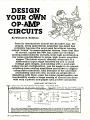
DESIGN YOUR OWN
OP AMP CIRCUITS
IC TESTBENCH
1D
r,
i
98C
36286
4
i
sullaupyER
vow-co
E1vER
Lab ÓÑZCS
ELECTBpOK
NYouYSel:
case you're not all that familiar
with us, we're not a publication for
electrical engineers and other
wizards. No way, ELECTRONICS
HANDBOOK Is expressly for people
who Ilke to build their own projects
and gadgets -and maybe get a
little knee -deep In tape, solder and
wire clippings In the process.
In fact, we have a sneaking
suspicion that our readers Ilke us
because they think we're Just as
bug -eyed and downright crazy over
great new project Ideas as they are.
And guess theyre rights
ELECTRONICS HANDBOOK thinks of
you who dig electronics as the last
of a special breed. It's more than
Just the "do-it- yourself" angle -It's
also the spirit of adventure. In this
pre- packaged, deodorized world,
building your own stereo system,
shortwave receiver, darkroom timer
or CB outfit Is Ilke constructing a
fine-tuned little universe all your
own. And when it all works
perfectly- it really takes you to
another world.
In
I
IF YOU'RE NEW TO ELECTRONICS YOU
GET
A "BASIC COURSE "!
a complete, ground floor lowdown on a variety of
Important electronic subjects. For
It gives you
example-Understanding
Transistors...How Radio Receivers Pull
in Signals...Cathode Ray Tubes
Explained...How Capacitors
Work...Using Magnetism In
Electronics, and much, much morel
Of course, we can't make you a
master electrician overnight. But we
can show you the fundamentals of
repair plus maintenance tips.
TRY
A
FEW ISSUES
AND EVALUATE OUR...
HOW- TO-DO -IT HELP Tips
and
pointers that add up to money
saved. For example tuning up your
tape player...all about radios ...whys
and hows of tumtables...care and
feeding of speakers.
-
EXCITING DISCOVERIES. Whatever
your particular Interest In electronics,
you'll be entering a world of
discovery In the pages of the
ELECTRONICS HANDBOOK
other training shows you
how to troubleshoot and
service computers like NRI!
No
NEW!
386sx/20 MHz MINI
MONITOR
TOWER COMPUTER!
Features 32 -bit 80386sx
CPU, 1 meg RAM, 64K ROM,
1.2 meg high -density floppy
disk drive
High- resolution,
nonglare, 12" T n.
monochrome
monitor with tilt
and swivel base
NEW! 40 MEG
DIAGNOSTIC HARDWARE
HARD DISK DRIVE!
AND SOFTWARE
You install this
40 meg IDE
hárd disk drive
interny, for
greatealldar ta
storage capacity
SOFTWARE
DISCOVERY LAB
Train with MS -DOS, GW- BASIC,
Complete breadboarding
system lets you design and
modify circuits, diagnose
and repair faults
and popular Microsoft Works
applications software
R.A.C.E.R. plug-in diagnostic
card and QuickTech menu driven software, both from
Ultra-X, give you hands-on
experience with today's
professional
DIGITAL MULTIMETER
Professional test instrument for
quick and easy measurements
DIGITAL LOGIC PROBE
Simplifies analyzing digital
circuit operation
LESSONS
t;
Clear, illustrated texts
build your understanding
of computers step by step
Only NRI walks you
-
.41
+1/.
elk
through the step -by -step
assembly of a powerful 386sx computer
system you train with and keep
giving you the hands -on
experience you need to work with, troubleshoot, and service
today's most widely used computer systems. Only NRI gives you
everything you need to start a mosey-making career, even a
business of your own, in computer service.
No doubt about it: The best way to learn to service computers is to actually
build a state-of-the-art computer from the keyboard on up. Only NRI, the
leader in career-building at -home electronics training for more than 75 years,
gives you that kind of practical, real -world computer servicing experience.
Indeed, no other training in school, on the job, anywhere
shows you
how to troubleshoot and service computers like NRI.
-
-
-
Get inside the West Coast 386sx computer system ... and
experience all the power and speed of today's
computer technology!
With NRI's exclusive hands-on training, you actually build and keep the
powerful new West Coast 386sx /20 MHz mini tower computer system.
You start by assembling and testing your computer's 101 -key "intelligent"
keyboard, move on to test the circuitry of the main logic board, install the
power supply and 1.2 meg high -density floppy disk drive, then interface your
high-resolution monitor.
What's more, you now go on to install and test a powerful 40 meg IDE
hard disk drive today's most -wanted computer peripheral included in
your course to dramatically increase your computer's data storage capacity
while giving you lightning-quick data access. But that's not all!
-
-
Professional diagnostic hardware and software makes
troubleshooting fast and accurate
Your NRI training now includes a remarkable diagnostic package that allows
you to quickly locate and corred defects in IBM XT, AT 80286/80386, and
compatible computers.
You'll use your Ultra -X QuickTech diagnostic software to test the system
RAM and such peripheral adapters as parallel printer ports, video adapters,
and floppy and hard disk drives. You'll go on to use your R.A.C.E.R. diagnostic
card, also from Ultra -X, to identify individual defective RAM chips, locate
interfacing problems, and pinpoint defective support chips.
This ingenious diagnostic package is just one more way NRI gives you the
confidence and the know-how for advancement, a new career, or a moneymaking business of your own.
No experience necessary ... NRI builds it in
With NRI, you learn at your own pace in your own home. No classroom
pressures, no night school, no need to quit your present job until you're ready
to make your move. And all throughout your training, you have the full
support of your personal NRI instructor and the NRI technical staff, always
ready to answer your questions and give you help whenever you need it.
FREE
catalog tells more. Send today!
Send today for NRI's big, free catalog that describes every aspect of NRI's
innovative computer training, as well as hands-on training in TV /video/audio
servicing, telecommunications, industrial electronics, and other high-growth,
high -tech career fields.
If the coupon is missing, write to NRI School of Electronics, McGraw -Hill
Continuing Education Center, 4401 Connecticut Avenue, NW, Washington,
DC 20008.
IBM is a registered trademark of International Business Machines Corp. QuickTech
and RACER. are registered trademarks of Ultra -X, Inc.
SEND TODAY FOR FREE CATALOG
MSchools
%ñ11
McGraw-Hill Continuing Education Center
4401 Connecticut Avenue, NW, Washington, DC 20008
For career courses
approved under GI Bill
check for details.
Check one FREE catalog only
Telecommunications
Computer Programming
Security Electronics
Electronic Music Technology
Desktop Publishing
Basic Electronics
PC Software Engineering Using C
MICROCOMPUTER SERVICING
TV/Video /Audio Servicing
Industrial Electronics & Robotics
Name
(please print)
Age
Accredited Member, Notional Home Study Council
22-iiJ
Address
City/State/Zip
ELECTA flICS
HAflOB
1
CONTENTS
Publisher Editorial ... 4 Build Your Own
The Future Of
Compass
Electronic
33
64
Solar Energy
From The Editor's
Desk
6 Build A VarioNew Products Parade .. 8 Coupler Receiver .... 41 Solid State Update .110
.
....
New Book Reviews
Design OpAmp
12
Expert Guide To Project Construction Quickie
83
47 Curiosity Detector
Building
.
Circuits
18
Catalog Corner
Crystal Oscillators ... 26 Understanding
Basic Electricity ..... 59
84
1t7P-1(--CIRCUIT
FRAGMENTS
Code Oscillator
Super Signal Booster
Water Level Detector
.
Double Feature
,
Negative Power Supply
Touch Control
Basic Pulse Maker
Telephone Voice
IC TESTBENCH 73
The Waveshapor
A
A
2
Crystal Controlled
19
Switch With
Memory
/ ELECTRONICS HANDBOOK
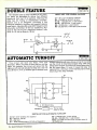
Automatic Turnoff
Home Intercom System
Mag Tape Amp
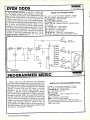
Even Odds
Tape Player
Burglar Alarm
Power Mike Amplifier
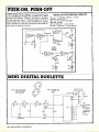
Push -on Push -off
Mini- Digital RoulIette ...
Do- It- Yourself Delay
.
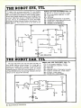
The Robot Eye TTL
Programmed Music
The Robot Ear TTL
Two -Tone Alarm
LED
WORKBENCH
52
PROJECTS
TTL
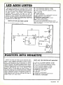
Adds Luster
Positive Into Negativo
CMOS Logic -al For RF
.
SELECT 5 BOOKS
for only
bwti,55,>.} and
DISCHARGE
PRüTEC190N
,1t
k;rairiegç
ISO EQUIPMENT
$4
(values to $112.75)
3260P 514.95
_----
EIFCTRCSTAïK
3329
929.95
Counts as
$18.95
2867P
2
'
SECOND EDITION
$60.00
Counts as 3
1938
2925P
$9.95
II)( rilìLll,
`.// 'f,/[
1
ELECTRO$4C
CONVERS'ONS
Symbols aal
Formulas
T'14C7 üCK.4NV5
3258
$27.95
Counts as
3632
33217 516.95
2
Ursa
MClphs
.:09111908 006
$18.95
Your most complete source for electronics
books for over 25 years.
ill'
J
4-:
2865P
Troubleshooting
& Repairing
SURE HUR
ow
r,
Re;
SIAN
PC
VCRs
BMW"
MIY SAYE A
tnmxs
ßcli nlals
SECOND EDITION
536.95
3279
3241P $16.95
$29.95
3627
Counts as 2
510.35
-
Counts as 2
,
stl
HOME,
RIEtAL
ELECTRICAL
MIYVtmsgsrr Ora1
ALARMS
3414
539.95
Counts as 2
3072P
3374P
016.95
$16.95
3628
$26.95
Counts as
2
Gordon McComb
Membership Benefits
2596P
2980P 310.95
514.45
1
GORDON MCCOHB'S
TIPS 8 TECHN10EES
FOR THE
ELECTRONICS
HOBBYIST
EM;;;;;;;:11/II
27507 S'4.95
^
Big Savings. In addition to this introductory
offer, you keep saving substantially with members' prices of up to 50% off the
publishers' prices. Bonus Books. Starting immediately, you will be eligible
for our Bonus Book Plan, with savings of up to 80% off publishers' prices. Club
News Bulletins. 15 times per year you will receive the Book Club News, describing all the current selections- mains, alternates, extras -plus bonus offers and
special sales, with scores of titles to choose from. Automatic Order. If you
want the Main Selection, do nothing and it will be sent to you automatically.
If you prefer another selection, or no book at all, simply indicate your choice
on the reply form provided. You will have at least 10 days to decide. As a member, you agree to purchase at least 3 books within the next 12 months and may
resign at any time thereafter. Ironclad No -Risk Guarantee. If not satisfied
with your books, return them within 10 days without obligation! Exceptional
Quality. All books are quality publishers' editions especially selected by our
(Publishers' Prices Shown).
Editorial Board.
3485
S27.95
Counts as 2
ELECCRONIC;S
FIPTd ElITCN
$39.95
522.95
Solid-State
THTORi.
Blue Ridge Summit, PA 17294 -0810
FIX f? B4Qs
Please accept my membership in the Electronics Book Club and send the 5 volumes listed
below, billing me $4.95. If not satisfied, may return the books within ten days without obligation and have my membership cancelled. agree to purchase at least 3 books at regular
Club prices during the next 12 months and may resign arty time thereafter. A shipping /handling charge and sales tax wil: be added to all orders.
How to Rood
Electronic Ciren t.
Diagrams
2880P
2883P
3275
ELECTRONICS
I
Counts as 2
PROJECTS
ELECTRONJCS BOOK CLUE'
ELECTRONICS
I
3345
(ONT BOO Si
ELECTRONICS
$24.95
Counts as 2
EiÖME
1
THE
1367P
THE
ILl.t`.STRATED
DICTIONARY
00
i+.?Mß^Yp±x>iPY
3777 $32.95
Counts as 2
2926
$14.95
525.95
518 95
1911.11}1lTtI)ti11
TISI Hs HAIL s, T
Name
Bask
Electronics
Course
The TAB
$16.95
2613P
$17.95
All books are hardcover unless number
is followed t>' a "P" for paperback.
-'
City
State
2800P
Service Manual fa
CCTV and MA
Address
-
-._
Signature
Zip
_
_._
-_-
_
-
Phone
-
- --
--
valid for new members only. Foreign applicants will receive special ordering instructions. Canada must remit
in U S. currency This order subject te acceptance by the Electronics Book Club
CEHB1091
3343
$29.95
Counts as
2
3475
$27.95
Counts as
2
-1991 ELECTRONICS BOOK CLUB
Blue Ridge Summit, PA 17294 -0x10
GETTING STARTED WITH
ELECTRONIC PROJECTS
Once you've decided to put together the parts that make up a
circuit there are several things that you should do before
starting actual work. The first is to understand exactly how the
circuit works; what each part does in the circuit. Don't just put it
together hoping it will work. You can be sure you have put it
together properly, so that it'll work, only if you know what each
component does to the flow of electricity (electrons) going
through it, as well as through the rest of the circuit.
If you don't understand the circuit thoroughly, every part as
well as its function, read the article again, carefully, until you
do. If that's not enough, look up words you're not familiar with
in a good electronics dictionary. Read the "teaching" articles
that we include in every issue of the ELECTRONICS HANDBOOK,
like the ones on "Capacitors" and "Resistors" and "Understanding Schematic Diagrams" that we have published in previous
issues.
Another caution is in order, even if you've worked with
electronic parts before but haven't handled integrated circuits
(ICs). Be sure to observe these simple precautions:
Don't mount the IC directly into a circuit or solder its
terminals into the circuit. Instead, do what experienced
experimenters do- solder an IC socket into the circuit (unless
you're using a quick-assembly experimenters board, in which
case you'll just plug the socket into the board's holes). Also,
don't handle the IC any more than necessary, to keep from
damaging it with static electricity. Most ICs are sold mounted
temporarily in a little piece of anti -static foam. Keep the IC in
its foam mount until you're ready to plug it into a socket.
Finally, keep excessive heat away from ICs, particularly when
putting them into a circuit with a soldering iron (another good
reason to use a socket whenever possible).
bl.
D.trQt
Don Gabree,
-Publisher
WANTED: PROJECTS
How would you like to find your own home -brew project in a future issue of the ELECTRONICS
HANDBOOK? It could happen. It's up toyoul Build your project foryourself...lt should have a real
purpose. Then, if you think that it is good enough to appear in the ELECTRONICS HANDBOOK,
let us know about it...
Write us a brief letter describing your project. Tell us what the project does. Provide us with a
legible schematic diagram and a few black- and -white photographs of the project...photos, with
good contrast, are important. After we have read your letter describing your project, we'll let you
know, one way or the other, whether we would like to purchase your article describing the
project.
If you would like some "Editorial Guidelines ", send us a S.A.S.E. with your request...All
correspondence should be addressed to:
C &E HOBBY HANDBOOKS
P.O. BOX #5148
NORTH BRANCH, N.J. 08876
4
/ ELECTRONICS
HANDBOOK
AMAZING
ELECTROnICS
`
HAfloBi
PUBLISHER
AND
EDITORIAL DIRECTOR
Don Cabree
SECRETARY /TREASURER
L. M. Gabree
ASSOCIATE EDITOR
Holly Love
CONTRIBUTING AUTHORS
Homer Davidson
Walter Sikonowlz
Tonyy Lee
Steve Sokolowski
Hugh Gordon
William R. Gross
William R. Hoffman
Ralph Hubscher
Ron C. Johnson
Joe O'Connell
Jeff Orthober
Glenn Rawlings
SCIENTIFIC & ELECTRONIC
PRODUCTS
LLISiK
LHC2K
W LC7
-
c
á c
LL
a
u+
g
W
RUB4
LGU40
LLSi
SD5K
EML1K
C.,
MCP1
0'
LEV1
10G3K
5
z
w c
c,,
a
,.
LG5K
BTC1K
BTC3K
f
BTC5
g 2
= a
s
2
`
JL3
GRAi
rL
PFS20
''
DPL20
ITM10
L3
a ó
z
E
V
H
NIG9K
EMA1K
°
ca
c
ii
1.5 MillionVollsTeslaCoilPlans
Jacobs Ladder -3 Models Plans
Anti Gravity Generator Plans
Plasma Fire Saber Assembled
Dancing Plasma to Music and Sounds Assembled
100,000 Volt Intimidator up to 20' Assembled
Invisible Pain Field Blast Wave Gen Assembled
PSP4K
Phasor Sonic Blast Wave Pistol Kit
LIST10
Infinity Xmtr, Listen in Via Phone Assembled
TAT30
Automatic Tel RecordingDevice Assembled
VWPM7K 3 Mi. FM Auto Tel Transmitter Kit
FMV1K
3 Mi. FM Voice Tranumitte, Kit
HOD1K
Homing/Tracking Beeper Transmitter Kit
$159.50
$199.50
$44.50
$20.00
$20.00
$199.00
$20.00
$299,50
$59.50
$15.00
$10.00
$10.00
$149.50
$69.50
$34.50
$99.50
$54.50
$49.50
$249.50
$20.00
$15.00
$10.00
$69.50
$79.50
$129.50
$74.50
$59.50
$199.50
$24.50
$49.50
$39.50
$49.50
EASY ORDERING PROCEDURE TOLL FREE 1 -900. 221.1705
or 21HRSON1.603.673.4730or FAX ITTO1 -603- 672.5406
VISA, MC. CHECK, MO IN US FUNDS. INCLUDE 10% SHIPPING. ORDERS
$100:oo A UP ONLY ADO $10.00. CATALOG $1.00 OR FREE WITH ORDER.
_'
INFORMATION UNLIMITED
PO .
ADVERTISING SALES
C &E Hobby Handbooks
P.O. Box #5148
(201) 231 -1518
ElectromagneticColl Gun Kit
Hi Velocity Coil Gun Plans
Levitating Device Plans
Electronic Hvonotism Technioues Plana
75,000 Volt OC Variable Output Lab Source Kit
Ion Ray Gun Kit, project energy without wires
12V/115 VAC Hi Out Neg Ion Generator Kit
Telekinetic Enhancer/Electric Man Assembled
Lightning Display Globe Kit
Worlds Smallest Tesla Coil Kit
250KV Table Top Tesla Coil Kit
EHI
ISSN 0897 -7631
North Branch, N.J. 08876
3mw Vis Red Laser Diode System Kit
Laser Beam "Bounce" Listener Kit
Visible Simulated 3 Color Laser Kit
40 Watt Burning Cutting Laser Plans
Hi Powered Pulsed Drilling Laser Plans
1 to 2mw HeNe Vis Red Laser Gun Assembled
Laser Lite Show -3 Methods Plans
See in the Dark Kit
VRL2K
BOX »B. DEPT. HB,AMHERST,NH03031
TELL
L.
Published by C &E Hobby Handbooks, Inc. Editorial and Business address, P.O. Box #5148, North
Branch, N.J. 08876 (201) 231 -1518. PERMISSIONS: Material in this publication may not be
duplicated or reproduced in any form without
permission. Requests for permission should be
directed to
Don Gabree, C &E HOBBY HANDBOOKS, INC. P.O. Box #5148, North Branch, N.J.
IF TOU'YS
MOVED
.
v.
-
US
/
"
r
T
'
e
A
j
r
f
08876 (201) 231 -1518.
EDITORIAL CONTRIBUTIONS must be accompanied by return postage and will be handled with
reasonable care; however, the publisher assumes
no responsibility for the return or safety of manuscripts, artwork or photographs. All contributions
should be addressed to: PUBLISHER, C &E
HOBBY HANDBOOKS, P.O. Box #5148, North
Branch, N.J. 08876.
As a service to readers, C &E HOBBY HANDBOOKS publishes available plans and /or ììn formation relating to products, techniques of
scientific and technological developments. Because of possible variances in the quality and
condition of materials and workmanship used by
readers, C &E HOBBY HANDBOOKS disclaims
any responsibility for the safe and proper functioning of reader -built projects based upon or from
plans and /or information published by C &E
HOBBY HANDBOOKS.
Second Class Entry applied for. Copyright © 1991
by C &E HOBBY HANDBOOKS, INC.
ATTACH LABEL HERE
NEW ADDRESS HERE
PLEASE PRINT
NAME
ADDRESS
aTV
DATE
STATE
ZIP
V 10
VOLUME
X
5
FROM
THE EDITOR'S DESK
Got
Ask The Editor,
He Knows!
a
question or
a
problem with
a
project
-
Please remember that The
Editors' column is limited to answering specific
electronic project questions that you send to
him. Personal replies cannot be made. Sorry,
ask The Editor.
to:
Inscrutable Japanese TV
Spies Like Us
Recently returned from Japan,
and brought a Japanese -model
Nintendo and cartridges home
with me. Now find that their TV
Do you have any information
about obtaining kits or schematics
I
I
I
signal is different from the
American signal, and my trusted
toy won't work on my set.
Is there a commercially made
adapter available, or is it possible
to make one? What is the
difference between the signals?
will appreciate any help you can
give me. You see several of my
cartridges are exclusive to the
Japanese market and are unavailable here, i.e., Japanese chess, go,
and Chinese chess.
-Dale Oldfield, Pinedale, WY
I
According to the references that
I
have checked, Dale, there is no
difference between Japanese and
American television signals. Both
nations use the NTSC method of
encoding. Assuming that your
Nintendo was not damaged in
transit, the only reasonable
explanation for the incompatibility
you've experienced is that
Japanese frequency assignments
for the various channels are
different from ours. That being the
case, it may be possible to retune
the output of your Nintendo so that
it falls on one of the standard
American channels. Such an
adjustment would probably be
effected by tweaking a variable
capacitor or inductor. I'd write to
Nintendo of Japan and see what
they have to say. (Their U.S.
affiliate may not know anything
about the Japanese product.)
Perhaps they will allow you to
exchange your Japanese model
for an American model if retuning
is not possible.
for the following: electronic
dissolution of memory devices,
using infrasonic sound waves;
ultrasonic sound devices for
crowd control; laser or microwave
transmitters? Also, do you have
information on detecting dentally
implanted transmitters used by
such agencies as the FBI, CIA, etc.
Thank you for your prompt
attention.
-R.G. Hellstrom, Lexington, KY
I'll answer your questions in the
order you've presented them.
Devices capable of obliterating
memory are beyond the editorial
scope of this magazine. Electronics Handbook is supposed to be
"the fun way to learn electronics,"
and to be honest, R. G., scrambling
someone's brains with infrasonic
acoustic energy doesn't sound like
much fun -not for the victim,
anyway.
Ultrasound devices designed to
intimidate dogs and other
attackers are available from a
variety of sources. Information
Unlimited (P.O. Box 716, Amherst,
NH, 03031) offers several plans
and kits. Note that ultrasound
devices by themselves may not be
sufficient to control a large, hostile
crowd of people, particularly if
they all stick their fingers in their
ears.
I assume that your interest in
laser and microwave transmitters
stems from a desire to eavesdrop
on a building with restricted
access, where it would be
impossible to plant a microphone.
The Russians used this method to
spy on our embassy in Moscow
during the early sixties. They
concealed
6
/ ELECTRONICS HANDBOOK
a
circuit design service. Write
The Editor
C &E HOBBY HANDBOOKS INC.
P.O. Box #5148
North Branch, N.J. 08876
he isn't offering a
cavity resonator
i
inside the Great Seal of the United
States, which hung above our
ambassador's desk, and bombarded the resonator with a beam
of microwave radiation whenever
they wanted to listen in. The
beauty of the scheme was that the
cavity resonator was a passive
device and thus almost impossible
to detect. I don't have any
information on microwave eavesdropping, but an article entitled
"Build the Laser Listener" by
Richard Pearson, which appeared
in the October 1987 issue of Radio Electronics, tells all you need to
know about laser eavesdropping.
Detecting the presence of a
transmitter is accomplished by
intercepting its signal. Professional spooks rely on expensive
scanning receivers for this
purpose, but all you really need is
an ultra -sensitive field- strength
meter capable of being tuned over
the frequency range of interest
typically,
-
50 to 500 MHz.
Information Unlimited offers plans
and kits for a bug detector that
should serve your needs.
Just as the eighties are
remembered as the decade of
personal computing, it may well be
that the nineties will be remembered as the decade of personal
espionage. There are shops now in
New York and other large cities
where spy gadgets of all kinds are
openly sold, and it's not just the
weirdos and Pl's who are buying
them. People from all walks of life
apparently feel the need to spy on
those around them. In most cases,
when we speak out against the
invasion of privacy, it's Big Brother
who is the villain, but I'm
beginning to feel that Pogo came
closer to the truth when he said:
"We have met the enemy, and he is
us."
your opinion of these tools?
Eico 460 Dead at 30
Just by chance picked up your
magazine at a drug store last year.
have since ordered five back
issues and have enjoyed them all.
My reason for writing at this time is
have an
to ask for your help.
oscilloscope, an Eico 460, which
ordered from Allied back in 1960
as a kit. It gave me good service for
a long time, but now it needs some
TLC. I'd like to know where can
get service data for this instrument.
-M. M. Campbell, Woodstock,
GA
-Joe
Toms, Forest Hills, NY
I
I
I
I
I
At one time, Eico was Heath's
major competitor, but unfortunately the company went out of
business years ago. I imagine that
any of the major service organizations that specialize in test
instrument repair could fix your
scope, but the cost might be
prohibitive. You might try Tucker
Electronics (1717 Reserve St.,
Garland, TX, 75042) and see how
much they charge. Perhaps they
would sell you a photocopy of the
Eico service data. If any of our
readers have service data for the
Eico 460 and are willing to help M.
M. out of his predicament, drop us
a line, and we'll put you in touch
with Mr. Campbell.
First of all, thanks for the tip
about Micro -Mark, Joe. Their
catalog looks like a good one. The
devices in question small,
benchtop- mounted table saws
and jig saws-are intended for use
-
by model builders, but I see no
reason why they should not also
do a good job of cutting PCB
laminates. Just be sure to use a
very fine saw blade. When sawing
glass- epoxy, commercial fabricators of PCBs use carbide- tipped
blades, because glass -epoxy is a
very abrasive and rapidly dulls a
conventional steel blade. For
home use, however, a conventional carbon -steel blade will be
satisfactory. Paper -base phenolic
laminates (XXXP) are much less
abrasive than glass- epoxy, by the
way.
Fast Beat, Slow Feet
need any information you can
provide on a 12 VDC motor -speed
control that could be applied to a
tape cassette player. am trying to
help a group of young people in a
I
I
clogging club. Clog dance music
is usually fast, and we wish to
control the tempo of new tunes
while learning them or while
teaching new members. Can you
More Thoughts About Tools
help? am thinking in terms of a
am writing this letter to call
chopper -style control.
your attention to an article on -R.T. McMillan, Huntington, WV
"Essential Tools for Electronic
A friend of mine, a retired
Construction" by Walter Sikonowiz
(Vol. VII of Electronics Handbook). professor of electrical engineering,
The question Walter brings up describes clog dancing as one of
about straight -line cuts in PCBs is the few forms of exercise that you
don't have to be a masochist to
always something of a problem.
priced the Kepro Model MS -6 enjoy. Clog dancing, which has its
shear and found it to be rather origins in the Appalachian region
expensive. The alternative, using a of the United States, takes its name
nibbler, gets to be rather tiresome. from the distinctive wooden -soled
clogs that the dancers wear on
A friend at work suggested that
try the following company, which their feet. When the dancers kick
specializes in small tools: Micro - up their heels, the clogs make a
Mark, 340 Snyder Ave., Berkeley pleasant clattering rhythm as they
Heights, NJ, 07922. have xeroxed hit the floor.
Getting back to the question at
three pages of their catalog
containing alternative devices to hand, R. T., I think that the use of a
deal with this problem. What is chopper -style speed control
I
I
I
I
I
would, in this instance, be overly
ambitious and expensive. All you
need to do is insert a 50- or 100 ohm potentiometer in series with
the "hot" power lead running to the
motor that turns the capstan and
take -up reel in your cassette
recorder. Increase the resistance
(by rotating the shaft of the pot)
until the speed has decreased to an
acceptable level. Needless to say,
you should make these modifications on a cheap, expendable
cassette deck. More expensive
cassette players will sometimes
have a built -in speed adjustment.
For example, the Sony Walkman
WM -D6 allows the tape speed to be
varied by 15 %, which might be
enough for your purposes. The big
disadvantage of trying to control
the tempo of music by varying the
tape speed is that the pitch of
individual notes is also affected.
Cutting the tape speed in half, for
example, cuts the tempo in half and
lowers all the notes one octave,
making your fiddle sound like a
cello.
How Long Do CDs Play?
bought a CD of my favorite
chart-toppers and it had only 13
cuts, totaling 36 minutes and 44
seconds of music on it. Is there
some reason we can't get a full
hour or so when we pay $15 or
more for a CD? And what's the
most they can put on a CD,
anyhow. Melvin Danzig, Perth
Amboy, New Jersey.
I
-
You're right, some record
producers do put surprisingly
small amounts of music on CDs. It
seems to be the decision of the
company to put out just what the
artist (and the A & R supervisor)
want to release on a new disc.
They could easily put more music
out at little increase in cost to
them; at least 60 minutes. Up to 70
or more minutes can be fitted on
todays CDs. For example, Arista
has 25 tracks for a total of 72
minutes, 30 seconds on the
recently- released Monkees Then
and Now CD.
VOLUME X
7
NEW
PRODUCTS PARADE
Its. Inn calle
Irreal
HAM-TIME
.rcwd rid .orIA
Ile It
OM
FA
Ì
P
P
Leal / OUT dud dlaplay
Seem dus
U8 Use tsr dl.play
Audabl. Uni Indictor
Sport. / Letterman. dud thew
MI
dus deck
Event a.unbdeven thew
12 beur
24 Mur sein.
Cltlec ay the world time sane dlepl.y
Um, plegrammable Um. .en. display
Fully fiuuUenal
dlataa
U
ñÎi
flits
1
°ÎI
FOI
I2'1MB
ASl
7'1248
Is
LOI
alplltk
S.naral
Cl
8'1E18
1111m
3A8
S'1é8
TA
11
Sunday October 891989
11_I (aI_; 1_I
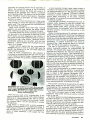
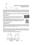
Just when you think that you
have seen it all, you find that you
haven't scratched the surface.
From ECode Systems, Inc. we
find that they have introduced a
digital clock simulator, designed
primarily but apparently, not
exclusively, for the Ham radio
operator that will make life easier
around the "Radio Shack" and
appropriately called "Ham- Time."
If you are not into Ham radio,
you might adapt it to numerous
other practical functions in your
daily routine, such as your
photographic darkroom. Its
versatility will challenge your
imagination.
For the Ham radio operator,
however, the Ham -Time is
designed for both Desktop and
Laptop computers. It will let you
give function to your idle MS -DOS
computer. In the "Radio Shack,"
Ham -Time provides the perfect
way to check local and GMT
quickly. The built-in time zone
displays allow you to quickly
determine the time anywhere in
the U.S.A. and Canada or, for that
matter, anywhere in the world,
with a user programmable screen.
Specifically, the Ham -Time
performs the following functions:
Local /GMT dual display
Snooze Alarm
U.S. time zone display
Audible time indicator
Sports/Laboratory dual timer
Fully functional alarm clock
Event count -down timer
12 hour or 24 hour modes
Cities of the world time zone
display
User programmable time zone
display
/ ELECTRONICS HANDBOOK
99l
11^8
17n1
I:nnNln
la
HAM -TIME
8
PorUlc
Sunday October 891989
P
IS
Dlei.y for United Suba
ktal MI
aa
f
Zone
r--
M
IW
-n
Fu"'
It
L
l
EUEÑ
(EP 1E;kJ: rii%i Ed
> tUWLI tIWLJ
ILLwAL!l li tl(L41
The "Event" timer allows the
user to count down the amount of
time remaining in a given event.
This counter can be set from one
second to 99 minutes. It counts off
the time in 1 /10th second
increments. The timer can be
suspended at any time. When
restarted, the timer begins from
the suspended value. The user
also has the option of having an
audible alarm sound when the
event has counted down to 00:00.
The "Event" counter comes in
handy for timing speeches and
presentations, or code practice.
The large display makes it easy to
read the remaining time from
across large rooms.
The "Lap" timer allows the user
to keep track of event times within
a total amount of time. Perfect for
auto racing, sporting events, or
laboratory experiments. The
counter increments in 1 /10 second
intervals. The function keys
control the counting of both the
lap time and the total time. The
space bar of the PC can be used as
a convenient way to control the lap
time. The large number display
makes it easy to read and record
time results as they happen.
The U.S. "Time Zone Display"
provides a quick way to get the
time across the country. This
display provides a means to check
the time in a remote part of the
country you are planning to call or
make schedule arrangements. The
time can be displayed in both 12
hour and 24 hour modes,
continuously being updated on
the minute.
The "Cities Around The World"
time display allows you to keep
track of the time anywhere in the
world. The display can be
operated in either 12 hour or 24
hour mode. This display can be
customized by preparing a text file
to substitute specific cities and /or
call signs in the same geographic
areas. This display can be
extremely helpful in understanding when international news
events are taking place or making
schedule arrangements with other
stations.
For readers who are interested,
"Ham- Time" has a modest price of
$24.95 and requires: CGA or EGA
graphics adapter, MS -DOS 2.1 or
later and 128K memory, available
in 3.5 or 5.25 inch disks. Address
questions to ECode Systems, Inc.,
335 West Virginia, Phoenix, AZ
85003 (602) 257 -1826.
ANALOG /DIGITAL DMM
Soar's 3200 Series 3 -1 digit
multimeters combine the features
of
a
state -of- the -art digital
multimeter with an analog bar
graph display. The high -resolution
3200 -count digital display delivers
the resolution of much costlier4 -1/2
digit meters for measurements
above 2,000 counts. The 32segment bar graph display is ideal
for readings that change
-
peaking, nulling and observing
trends. These DMMs are simple to
use. Just select your function with
the handy 8- position rotary switch
and test. The meter automatically
selects the range with the greatest
accuracy and resolution. The
function and measurement range
are even shown on the LCD
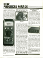
The SA -600 offers a safe 20V
handpiece with a 65W heating
element for excellent heat
recovery
The high
provide
allowing
and temperature stability.
mass desoldering nozzles
superior heat capacity,
efficient solder flow at
lower temperatures. Featuring
vacuum and hot air blow functions,
the SA -600 has a variable
temperature range of 660° F (350°
C) to 840° F (450° C).
display. Touching the RANGE
button on Models 3220 and 3230
prevents the instrument from
changing ranges, which saves
time for repetitive go /no -go
checks. Both models also have an
audible continuity feature which
causes the meter to beep when the
circuit under test is closed. After
pressing the DATA -H button on
Model 3230, the meter captures
the measurement, beeps, and
locks it on the display so you can
focus your attention on the probes
and circuit. With this data hold
feature, the DMM automatically
updates for each new measurement. All 3200 Series multimeters
come with safety test leads,
operator's manual, batteries, spare
fuse, and 3 -year warranty. And
each meter is priced under $100.
For further details write or call:
HMC Co. P.O. Box #526, Canton,
MA 02021 (617) 821 -1870.
DESOLDER STATION
OK INDUSTRIES addresses the
problem of desoldering PCB's with
high thermal demands by intro-
ducing
a
new high power
desoldering station. The SA -600
design incorporates a unique high
capacity nozzle, high power
heating element and quick -rise
vacuum pump (21 "Hg) to optimize
efficiency.
This desirable combination of
high vacuum pressure for suction
and high heat capacity nozzles
contribute to the SA -600 being a
performance leader for desoldering and rework operations.
The SA -600 is sold through OK
Industries authorized distributors
at a list price of $557.50. For more
information, contact OK Industries, Inc., 4 Executive Plaza,
Yonkers, N.Y. 10701 or call: 1 800523 -0667.
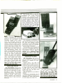
HANDHELD HOLDERS
MFJ Enterprises, Inc. announces the release of new Mobile and
Desktop HT Holders for only...
$9.95 each.
These handy new MFJ HT
holders help you make sure your
handheld stays where you put
in your car or on a crowded table
or desk. MFJ -24 has a strip of
durable plastic that bends to fit
snugly over your car door, front
seat or other area.
MFJ -25 stands on your table or
desktop.
They're an economical way to
help guard against dropping your
expensive HT. Both units provide
for both large and small HTs.
it-
For more information contact
any MFJ dealer or MFJ Enter-
prises, Inc.,
P.O. Box 494,
Mississippi State, MS 39762, or call
(601) 323 -5869, Telex: 53 4590
MFJSTKV, FAX: (601) 323 -6551, or
order toll free at 800 -647-1800.
VOLUME X
9
NEW
PRODUCTS PARADE
DIGITAL MULTIMETER
Beckman Industrial's Model
RMS225 is a full function, auto ranging, 4 -digit multimeter that
combines 10,000 -count resolution, true RMS measurement
accuracy, and a 41- segment
For further details, contact
HMC, 33 Springdale Avenue,
Canton, MA 02021, Phone (617)
821 -1870, FAX (617) 821 -4133.
analog bar graph display. With a
simple two -button menu selection
scheme, you can engage the four
special measurement modes of
Range Lock, Probe Hold, Relative
Mode and Auto Min /IV ax. Other
PROGRAMMABLE SOLDERING
STATION
From Contact East a new
programmable soldering station
that has a tamper -proof temperature setting, quick heat up, and
SHORTWAVE /AIRCRAFT
RECEIVERS
From Ramsey Electronics, Inc.,
Do -It- Yourself kits to build a
Shortwave Receiver that will tune
in the world with a 12" antenna
(SR -1 $27.95). This little Receiver
can receive any 2MHz portion
from 4 to 11 MHz. A true superhet
with smooth varactor tuning, AGC,
RF gain control, plenty of speaker
volume and runs on a 9V battery.
With SC-1 Shortwave Converter
Kit ($24.95), it can convert your car
radio to two switchable bands,
each 1MHZ wide -tunable on
your car radio dial... An opportunity to add some fun to your
drive time.
increased thermal recovery
permitting consistent, high quality
soldering, with less dwell time on
multilayered boards and heavy
ground planes. Temperature can
be set on the digital key pad, from
400° to 899° F, with an accuracy of
+/- 0.9° F. Once the temperature is
set, unauthorized personnel
cannot change the setting without
the programming card. The
temperature memory system
allows the iron to be shut off and
turned on without having to reset
the iron each time. The housing,
iron and cord are made of static -
dissipative material -ideal for
static -safe areas. Resistance to
ground is less than 2 ohms, and
leak voltage is less than 0.6mV.
Priced at $299.00, hobbyists
may find the cost a little steep for
their workbench but for the
hobbyist who has everything, this
has to be the ultimate in soldering
features include a battery- saving
Auto Power Down mode and
Overload Alert, which warns you if
the meter input ratings are
exceeded. The high performance,
dependable, and easy -to -use
Model RMS225 comes complete
with test leads, protective holster,
self -resetting fuse, and a 3-year
warranty.
10
/ ELECTRONICS
HANDBOOK
iron stations.
The station comes complete
with iron -holder, sponge, programming card, 50W iron (with
A1016 tip) and operates on a
115VAC (3 wire cord).
For additional details and /or
information, write or call Contact
East, 335 Willow Street, North
Andover, MA 01845 (508) 6822000.
Aircraft Receiver (AR -1 $24.95)
kit lets you listen to exciting
aircraft communications. Picks up
planes up to 100 miles away. The
AR -1 receives 110 -136 MHz AM air
band with smooth varactor tuning,
superhet with AGC, ceramic filter,
adjustable squelch, excellent
sensitivity and lots of speaker
volume. It runs on a 9V battery and
is ideal for air shows or just
hanging around the airport. 30
page manual not only provides
step -by -step instructions but
provides details on "pilot talk"
also.
Detailed instruction manuals
make these kits easy and fun to
assemble. For more information
contact Ramsey Electronics, Inc.,
793 Canning Parkway, Victor, N.Y.
14564. (716) 924 -4560, FAX (716)
924 -4555.
DIGITAL DECADE
SUBSTITUTERS
Substitution boxes are economical, indispensable tools used
in a variety of engineering, design,
troubleshooting and service
applications. With convenient
high impact plastic, these
substituters are very portable and
reduce clutter on a busy lab bench.
Four series of substitution boxes
are available: RS Series sets
resistance; CS Series sets
capacitance; RCS Series sets both
resistance and capacitance; and
LS Series sets inductance. For
details contact: HMC, P.O. Box
526, Canton, MA 02021
(617)
821 -1870
For more information call or
write: ADVANCED CABLE ELECTRONICS CORP., P.O. BOX
#1291, Westboro, MA 01581, Tel:
(508) 366 -0669.
-
CONTINUOUS LENGTH
CABLE TIES
Strap LocTM Continuous Length
Cable Ties reduce the need for
stocking many different lengths of
cable ties. The ties are cut from a
spool, assembled with a lock, and
used like any cable tie. No special
tools are required. Waste is
dramatically reduced because any
excess can be reused. Unique
features include ability to fasten
and bundle large objects, separate
and space wires and cables, fasten
through panels, and multiple
wrapping for extra high tensile
strength applications. Stainless
side -by-side thumbwheel switches, you can easily dial in the
desired resistance, capacitance or
inductance value.
These sustitution boxes are
used to set resistance, capacitance and inductance values for
engineering, design, troubleshooting and service applications.
Just dial in the desired value using
convenient side -by -side thumb wheel switches -no fumbling
with multiple slide or rotary
switches. Different colored
switches separate the various
impedance ranges. Since the
impedance values are set and read
directly, no mistakes can be made
as with rotary or slide switch
decade boxes. There's no need to
examine groups of switches
simply read one number. Made of
-
ILLUMINATED MAGNIFIER
The stylish 8MC Series lamps
utilize a 22 -watt circline fluorescent tube to cast an even glow on
your task for optimum brightness
and accuracy. It reduces eyestrain
and fatigue by combining the two
key factors in aiding vision -light
and magnification. The contemporary "floating arm" lets you
position the light source with the
touch of a finger, and keeps it in
place so your hands remain free to
perform other tasks. The 5 -inch
crown optical glass lenses are
available in 3- diopter ( +75%
magnification) and 5- diopter
+125 %). Another option is an 11diopter ( +275 %) lens system with a
3 -inch viewing area. For precise
inspection, a 4- power, 16 diopter
lens system is offered which meets
government standard MIL -STD(
steel and nylon locking device
features low insertion force,
instant locking, and infinite
adjustability. Strap L0cTM Continuous Length Cable Ties are now
available in two new smaller
package sizes (250 Ft. & 500 Ft.)
for added convenience and ease of
2000.
For more details, contact HMC,
33 Springdale Avenue, Canton,
MA 02021. Phone (617) 821 -1870,
FAX (617) 821 -4133.
use.
VOLUME X
11
NEW
BOOK REVIEWS
best efforts at maintaining it in
good condition. Excellent mechanical drawings show how to
dismantle equipment without
Key anatomical
damaging it
:
features are illustrated in numerous photographs. The author
targets common sources of
trouble, such as motors and
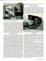
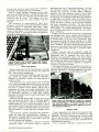
CAMCORDER MAINTENANCE
AND REPAIR
By Holmer L. Davidson
To most people, video equipment seems delicate and complex.
Thus, whenever a camcorder or
VCR fails to operate, their first
thought is not How can repair
this ?, but Where can find a repair
man? That's the way
felt, too,
until
read the new book by
Holmer Davidson and learned that
a wide variety of common ills can
be cured at home using nothing
more than a voltmeter, a screwdriver and some common sense.
The author begins by introducing us to the various video
formats such as VHS, VHS -C
8mm, Beta, and a handful of
derivatives. We learn the mechanical and electronic principles on
which these machines operate.
Lots of good diagrams make the
discussion easy to follow. Once we
understand how these devices
I
switches, and shows how to test
and repair them using a DDM and
some simple tools.
Every owner of video equipment
should realize that sooner or later
a malfunction will occur. When it
does, Camcorder Maintenance
and Repair will help you set things
right and perhaps avoid an
expensive trip to the repair shop.
The book costs $16.95 and is
available from TAB Books Inc.,
Blue Ridge Summit, PA, 172149988. Or ask for it at your local
bookstore.
I
I
I
work, the author discusses
maintenance, that is, how to clean
and lubricate the machines so that
they stay in good working order.
He also addresses the problem of
battery care and charging.
Videotape cassettes can sometimes cause problems, too, so
there is one chapter devoted to
cassette maintenance and repair.
The bulk of the book, however,
concerns itself with what to do
when the unthinkable happens,
when your expensive camera or
VCR grinds to a halt despite your
12
/ ELECTRONICS
HANDBOOK
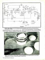
Forbes may interest you. The
Homebuilt Dynamo is a step -bystep, 182 -page guide to the
construction of a low- voltage, 3phase AC generator and rectifier
what we would call an alternator.
Based on high- energy permanent
magnets, Mr. Forbes' design is
unique in that it develops
considerable power at relatively
low speed. Maximum rate output is
1,000 watts at 740 rpm. Depending
on the rate of rotation and the
manner in which the coil windings
are connected together, output
voltages between 12 and 36 VDC
may be produced. Power to turn
the armature can be obtained from
a windmill, a water wheel, or even a
stationary bicycle, which is the
method employed by the author.
He uses the power generated to
charge a battery and light his
home using low- voltage fluorescent lamps.
The book has over 300 illustrations and is printed on high -quality
glossy stock. Instructions are
clear, but considerable mechanical aptitude will be needed to
duplicate the author's work. The
Home Built Dynamo is available
for $65 (U.S.) from Todd -Forbes
Publishing, P.O. Box 3919,
Auckland, New Zealand. Price
includes airmail delivery.
-
THE HOMEBUILT DYNAMO
By Alfred T. Forbes
Like ostriches with their heads in
the sand, Americans by and large
ignored the dangers of their
dependence on foreign oil during
the eighties, but Iraq's invasion of
Kuwait last August shattered their
complacency. People think more
about energy these days, and
some even dream of generating
their own electrical power. If you
are one of these people, this new
book by New Zealander Alfred
INVENTING: CREATING AND
SELLING YOUR IDEAS
By Philip B. Knapp, Ph.D.
The setting is
a
cheerless
basement laboratory. In the dim
light we see a strange machine that
appears to have been thrown
together from junk parts. Standing
next to the machine, a man badly
in need of a haircut and shave is
busy making adjustments with a
screwdriver. Oops! He must have
turned the wrong screw, because
the machine begins to shake and
emit puffs of smoke. Before the
man can correct his mistake, the
machine lets out a dying gasp and
explodes, sending gears and
springs flying through the air like
shrapnel. The man dives beneath a
table, then peers out cautiously.
We see in his soot-covered face a
mixture of surprise and stubborn
determination, and we know that it
won't be long before he's built a
new version of his silly machine.
Who is this character, anyhow?
He is a typical inventor, as seen
through the jaundiced eyes of a
Hollywood scripwriter. Little
wonder, then, that to many people
the word inventor is synonymous
with crackpot. The first thing
Philip Knapp does in his new book
is to lay to rest the hackneyed
stereotype of the inventor. Dr.
Knapp, himself an accomplished
inventor with 20 patents and more
than 50 inventions to his credit,
portrays the inventor as a creative
problem -solver, someone more in
tune with reality than most of his
detractors. The author goes on to
show us what inventing is really
like, using some of his own
inventions as examples. We learn
the painstaking process by which
an idea is transformed into a
working prototype.
Once a prototype has been built
and tested, the inventor must
decide how his device is to be
marketed. The first alternative is to
sell the invention to a company
and collect royalties. For someone
with no business experience, this
will probably be the best choice.
But how do you find a suitable
company? Not through one of
those classified ads that say
"Inventions Wanted." Most of
these people make their money on
the gullibility of the inventor, not
on the merits of his invention. As
Dr. Knapp says, run like hell as
soon as anyone asks you for a fee
to promote your invention. You'll
find the best sales leads for your
invention in the business section
of most public libraries, and the
book explains how to make use of
this information. The author also
discusses how to negotiate with a
company that's interested in your
invention. To protect yourself,
don't show them the prototype
until after the contract is signed.
Too many inventors have been
cheated out of their just rewards
by unscrupulous wheeler-dealers.
The alternative to selling your
invention to a company is to form
your own company and manufacture the invention yourself. For
most inventors without business
experience this could be the road
to ruin, but for those who prefer to
do it this way, the author furnishes
complete information on formulating a business plan, raising
capital, dealing with lawyers,
setting up a production line,
marketing the product, and
running the business. What he
doesn't cover you can find by
reading the books listed in the
extensive bibliography.
think this is a terrific book, and
a good value, too. Whither you
have a specific invention in mind,
or are just curious about inventing
in general, Inventing: Creating and
Selling Your Ideas is a book you
ought to read. The price is $15.95
and the publisher is TAB Books
Inc., Blue Ridge Summit, PA,
I
17214-9988.
THE EMPLOYMENT MAZE
By Paul Dombroski, David Hage,
and Dennis Hage
As America entered the twentieth century, most of its working
citizens were self -employed. They
were farmers, or shopkeepers, or
lawyers, or a hundred other things;
and they were their own bosses.
Today, on the threshold of the
twenty -first century, the situation
has reversed itself: big corpora-
tions and big government
dominate the economic landscape, and most people work for
someone else. Under such
conditions, the key to success may
not lie in working hard, but in
working someplace else.
Paul Dombroski, personnel
manager at an electronics firm in
the southwest, along with
associates David and Dennis
Hage, has written a book that will
enable the ambitious job- seeker to
find the kind of job he wants. The
author advocates establishing a
network of influential friends to
help in the job search, since the
choicest job openings are often
filled by personal recommendations and referrals. He tells how
and when to respond to employment ads, and how to write a
resume that will elicit a response
from
a
personnel manager.
Employment agencies are sometimes necessary in a job search;
Mr. Dombroski tells how to get the
most out of them. Once you've got
the attention of a prospective
employer, you face one last
hurdle: the job interview. How you
handle yourself in such an
interview is crucial to winning the
job you seek. Like or not, you have
to sell yourself and convince the
employer that he's found a
valuable asset. Mr Dombroski
offers welcome advice on how to
do this.
VOLUME X
13
NEW
BOOK REVIEWS
The Employment Maze is a fast paced 136 -page book that you can
read in an hour or two, yet the
information it contains could
affect the rest of your life. Copies
may be ordered from Paul
Dombroski Inc., POB 47604,
Phoenix, AZ, 85068. Price is $12.95
plus $2.00 for postage.
tone controller, stereo audio
switch, and various power -supply
circuits to power the projects
presented.
In
addition to the projects, there
are chapters on
TV and VCR
theory, assembly tips, reading
schematic diagrams, making
printed circuit boards, and
soldering. The book is thus a selfcontained introduction to project
building that will appeal to the
beginner as well as the more
experienced hobbyist. Most
projects require only two or three
integrated circuits and a handful of
other components, so you can
assemble them quickly and
inexpensively. PCB layouts
accompany most of the projects.
Customize Your Home Entertainment System is an excellent
book of projects, reasonably
priced at $15.95. Order from TAB
CUSTOMIZE YOUR HOME
ENTERTAINMENT SYSTEM
Books Inc., Blue Ridge Summit,
PA, 17214 -9988, or your local
bookstore.
By Steve Sokolowski
Popular author Isaac Asimov
recently marked a milestone in his
long career with the publication of
his 300th book.
mention this
because it appears as if Steve
Sokolowski has his sights set on
Dr. Asimov's record: this is the
I
third book of Steve's to be
reviewed this year, and it looks like
his best to date. This time out,
Steve brings us a collection of
easy -to -build projects designed to
add new features and enjoyment
to a TV, VCR, or stereo system.
The roster of projects consists of
22 items: tunable notch filter,
audio delay line, equalizer, noise
reducer, low- voltage power
amplifier, two -watt audio amplifier, four -watt audio amplifier,
rear -speaker ambience amplifier,
bass -boost filter, stereo audio
control, VU meter, audio power
meter, stereo simulator, infrared
audio transmitter and receiver,
surround -sound decoder, VCR AC
controller, stereo adapter for TV,
14
/ ELECTRONICS HANDBOOK
DESIGN AND APPLICATION OF
SMALL STANDARDIZED
COMPONENTS
By the Staff of Stock Drive Products
As electronic enthusiasts we
share a common interest: we like
to build things, great Rube
Goldberg-style contraptions with
whirring and clicking parts,
gadgets that amaze our neighbors
and cause even the most tolerant
spouses to grit their teeth. This is
our role in life, and we play it with
gusto. For inspiration, we read
Electronics Handbook and half a
dozen other electronics magazines, which, out of courtesy to our
publisher, shall remain nameless
here. These magazines provide a
vital forum for the dissemination of
the new ideas and techniques in
the field of electronics. However,
most projects are not strictly
electronic devices; they have a
mechanical structure as well, yet
can think of no popular periodical
I
that addresses mechanical
concepts in the same way that
magazines like Electronics
Handbook and others treat
electronic concepts. As a result,
the mechanical part of a project is
often approached with little or no
theoretical insight. Things are put
together in a trial- and -error
fashion from whatever mechanical
parts are at hand, and it is a
testament to human ingenuity that
many of these projects work at all.
As an antidote to the current
deplorable state of mechanical
knowledge, let me recommend the
Design and Application of Small
Standardized Components, an
easy -to- understand guide to the
theory and application of mechanical components like pulleys,
belts, gears, motors, and so on.
This book was prepared by the
staff of Stock Drive Products, a
major supplier of small, precision
mechanical components
The
purpose of this book is to explain
in simple language how best to
apply the mechanical components
that Stock Drive Products sells. Of
course, the information applies
equally well to components from
other manufacturers.
Chapter One is a compendium
of useful mechanical data, most of
it in chart form, dealing with such
things
as
conversion factors,
moments of inertia, properties of
metals, properties of plastics,
characteristics of finishes and
coatings, and practical hints for
mechanical design.
Chapter Two is an excellent,
thorough introduction to the
design and application of gears least the 1940's, and possibly
and gear trains. Let me point out, earlier. Back in those days, you not
however, that most home projects only built your own airplane, you
should probably be constructed built the transmitting and
with belts, chains, and pulleys, receiving equipment as well, and
since these are easier for the you had to have a ham license to
novice to lash together than a gear use the equipment. Things have
train. But for those times when you changed considerably since then.
just can't avoid using gears, Factory -built transmitters and
Chapter Two will pull you through. receivers are readily available, and
Chapter Three is about electri- you don't need a ham license to
city, probably nothing that you use them. You can still build your
don't already know. Chapter Four own airplane, if you wish, or you
is about motors, and here there is can buy one that's ready to fly.
likely to be lots that you don't
know. The treatment of stepper
motors is especially thorough.
Chapter Five deals with spring
motors, handy devices that can
replace an electric motor or a
counterweight in certain applica-
tions. Shaft couplings and
universal joints are discussed in
Chapter Six. Belt drives, chain
drives, and pulleys are explained
in Chapter Seven, which for most
readers will be the most important
chapter of the book. This chapter
is augmented by an extensive set
of center -distance tables which
make the design of belt- driven
systems easy.
Chapter Eight is all about shafts
and bearings, Chapter Nine deals
with techniques for the damping or
elimination of vibration, and the
book ends with a final chapter on
elements of robotic design.
To sum up, the Design and
Application of Small Standardized
Components is a 784 -page
handbook of practical mechanical
design. You don't have to be a
mechanical engineer to understand it, and you won't go broke
buying it, since the price is just
$7.95 (soft cover) or $12.95 (hard
cover). This book is available from
Educational Products, P.O. Box
606, Mineola, NY, 11501.
THE BEGINNER'S GUIDE TO
RADIO CONTROL SPORTS
FLYING
By Douglas R. Pratt
The flying of radio -controlled
model airplanes dates back to at
Before you even consider
buying a plane and an R/C control
suggest that
system, however,
you take a look at Douglas Pratt's
new book, The Beginner's Guide
to Radio Control Sport Flying. In it,
you'll find all the information
necessary to get started in R/C
modeling. Mr. Pratt is special projects director of the Academy
of Model Aeronautics, the national
organization for model fliers. He
knows a lot about planes and
flying, and he conveys what he
knows with good- natured enthuI
siasm.
One of the things that the author
stresses is the desirability of
joining an R/C modeler's club. For
the beginner, clubs provide
camaraderie as well as free advice
from more experienced members.
In addition, clubs carry insurance
that protects their members, so if
you lose control of your plane and
it crashes through someone's
window, the insurance company
pays the bill.
Most of the book is devoted to
the technical aspects of R/C flying.
For example, the author discusses
the operation of transmitters,
receivers, and servos. He stresses
the importance of periodic testing
of the control system to prevent
possible disasters in the air. And
he tells how third -order intermo-
dulation from other nearby
transmitters can cause you to lose
control of your plane.
Construction tips are sprinkled
liberally throughout the book.
There is even advice on choosing a
plane. For the beginner, a plane
that is easy to build and easy to
control makes sense. You want a
plane that is slow and stable, not
something designed for highspeed aerobatics. If your flying
space is limited, an R/C helicopter
might be the answer. On the other
hand, someone with lots of space,
who likes peace and quiet, might
prefer an R/C sailplane.
With the exception of the
sailplane, all planes need an
engine of some sort. The bigger
the plane, the bigger the engine
required. Most beginners start out
with an economical, 2- stroke
engine. These are ignited by glow
plugs and burn a mixture of
methanol, nitromethane and oil,
with methanol being the major
constituent. Since the fuel is very
flammable, caution is necessary.
Diesel and gasoline -powered
engines are also available. In
recent years, 4- stroke engines
have become popular, especially
with scale modelers, who prefer
the realistic rumble of a 4- stroke
engine to the thin whine of a 2stroke. A large 4- stroke engine
may put out 3 horsepower and
cost as much as $3,000.
Douglas Pratt's book was a
pleasure to read, and recommend
it without hesitation to anyone
contemplating the purchase of an
R/C model plane. The Beginner's
Guide to Radio Control Sport
Flying costs $9.95 and is published
by TAB Books Inc., Blue Ridge
Summit, PA, 17214 -9988.
I
VOLUME X
15
REMOVE IC'S
LEARN THE SECRETS OF HOW TO FIX
ELECTRONIC EQUIPMENT FASTER ON OUR
FASTER
REPAIR TECHNIQUES ON VIDEOTAPE
Learn our techniques and make more money repairing electronic
equipment. These tapes are packed with much practical information
that will save enough of your valuable time to quickly pay for the tapes.
Learn from an expert what fails, why it fails, how to find it faster, and
how tó fix it faster.
Much of this information is hvailable nowhere else.
These tapes start at the beginning for beginners, but cover each
subject so thoroughly that even old pros will learn valuable new
techniques and skills.
Send payment with order and we will pay shipping.
Order 14 tapes for $499.95 or send $575.00 for all 16 tapes.
How to use a Voltmeter (1 hr. 51 min.)
How to use a logic probe and logic pulser
All about resistors and their failure modes (1 hr.)
All about capacitors and their failure modes (1 hr. 28 min.)
All about inductors and their failure modes, Part I. Includes
$39.95
$39.95
$39.95
$39.95
inductors, transformers, flybacks, pinball coils, solenoids
$39.95
All about inductors and their failure modes, Part II. Includes
magnetic clutches, relays of all types, other devices (58 min.)
All about diodes and their failure modes. Includes rectifiers,
SCR's, Zeners, triacs, LED's (55 min.)
All about transistor failure modes (56 min.)
How to solder like a pro
with lots of time saving circuit board
repair techniques, including some of the fastest ways to
change IC's you ever saw (1 hr. 30 min.)
All about electrical contacts, connectors, connections and their
-
$114.95
(Remove 6 thru 64 pin IC's)
$39.95
-
How to troubleshoot digital integrated circuits
includes micro$39.95
processors, what goes wrong and how to find it, how to use the
best
literature
on
IC's
where
and
to get it (1 hr. 45 min.)
$39.95
$39.95
Job opportunities and money making opportunities
in electronics. (45 min.)
$39.95
$39.95 Troubleshooting and locating component failures. (1 hr. 10 min.)
$39.95
Power Supplies
Linear and Switching. (42 min.)
$39.95
-
-
failure modes, common and uncommon problems, symptoms,
good cures
How to use the oscilloscope (to track down digital failures)
How to read schematics and use them for troubleshooting, Part
Covers monitors, how to find monitor problems with wiring
diagrams, gives symptoms, where to look, covers both raster
scan and X -Y monitors (56 min.)
with this simple invention than any other method, including
$6,000 vacuum desoldering stations. Speed up your repairs
and salvage hundreds of good IC's per hour from junk boards.
Won't damage IC's or circuit board. This is a money making,
labor saving tool. Fits Radio Shack or Ungar soldering irons
soldering iron not included.
Complete set of 8 desoldering bits
(Remove 6 thru 40 pin IC's)
89.95
Complete set of 10 desoldering bits
$39.95
$39.95
VRS ELECTRONICS
I
P. O. BOX 813 -EH
SELMER, TENNESSEE 38375
TELEPHONE (601) 287 -1594
$39.95
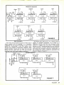
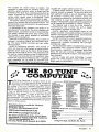
THE 80 TU
t)4 COMPUTER
The 80 -Tune Computer is a project which is not
only easy to build but also fun to use. Its uses are
many and are limited only by the imagination of
the builder. This is an excellent beginner's project
because of its simplicity. A masked microprocessor
(special Integrated Circuit, or IC) does all the work.
Any of the 80 songs can be selected by the
telephone -style keypad. A push of the Play button
makes the selection. The Stop button resets the
microprocessor. The selected tune will start each time
the Play button is pushed as long as power is on and no
Reset (or Stop) occurs.
Complete plans to build the "80 -Tune
Computer" $2.95
Ul Custom Microprocessor $9.00
PCB Printed Circuit Board $4.95
Add $2.00 for postage & handling
For each combination of the above items,
send check or money order (U.S. funds) to:
C &E Hobby Handbooks, Inc.
P.O. Box #5148, North Branch, N.J. 08876
16
/
ELECTRONICS HANDBOOK
BO
TUNS COMPUTER SOHO LIST
0 AMERICA
ANCHORS AWEIGH
BATTLE HYMN REPUBLIC
CAISSONS GO ROLLING
4 CALL TO COLORS
I CAVALRY CHARGE
E DIXIE
T HAIL BRITTANIA
1 YANKEE DOODLE DANDY
I LA MARIEILLAISE
10 MARINE HYMN
11 REVEILLE
1
2
3
12 STARS
STRIPES
13 TAPS
14 WILD BLUE YONDER
IS ALOUETTE
IS AIILVEULIICIII 11OMA
17 CAMPTOWN RACES
15 CANOY MAN
11
TO
CIIATTANOOGA C11OO.CI 100
CIE MENTINE
DALLAS 511E111
EL PASO
73 THE ENTERTAINER
21
n
7/ JU1.LS UUUU 111.10w
25 FUNERAL MARCH
74 IIAVA NAGILAII
27 IN HEAVEN IS NO DEER
24 JIMMY CRACK CORN
21 JINGLE BELLS
b KING OF ROAD
31
LA CUCARACHA
22 LONE RANGER
33 MODEL T
IS THE OLD GREY MARE
]S POPETE
RAINDROPS
37 SAILORS HORNPIPE
H SAN ANTONIO ROSE
31 SEE THE USA
40 OUT TO THE SALLGAME
41 TIJUANA TAXI
42 TWO BITS
43 WABASH CANNONUALL
44 SAINTS 00 MARCHINO
WOODY WOOPECKER
N YELLOW DOIT Of TEXAS
47 ACROSS THE FIELD
SS AGOIE WAR HYMN
45 ARKANSAS FIGHT SONG
)
.I
SO
II
S2
SIIAnP
UUU1(111UUNE11
SOW DOWN WASHINGTON
RE
Payment enclosed. to:
C &E
S) BUCKLE DOWN WINSOCKI
SS CHARGE
LS DEAR OLD NEBRASKA U.
w THE EYES OF TEXAS
IT ABOVE CAYUGA'S WATERS
Y FIGHT ON USC
SS GO, NORTHWESTERN
SO HAIL PURDUE
HEY LOOK ME OVER
HOLD THAT TIGER
N ILLINOIS LOYALTY
N INDIANA. OUR INDINA
M I'M A JAYHAWK
IR IOWA FIGHT SONG
II7 LOVE YA BLUE
N MICHIGAN STATE rIGUIT
S1 MINNESOTA ROUSER
70 NITTANY LION
71 NOTRE DAME FIGHT
77 OLE 1111
73 ON, SOAVE ARMY TEAM
74 ON WISCONSIN
7S WRECK FROM GA. TECH
74 ROLL ON TULANE
/7 Olt VICIUOE
TI WALNINOTON/LEE SWING
1
2
71 YEA
Hobby Handbooks
PLEASE PRINT
NAME.
ADDRESS CITYSTATE-
A
ZIP
Foreign Postage add $8.00...U.S. Funds
V
10
'f _ ""CLASSIFIED
FLEAMA KET
Digital Compass Kit
VHS -VCR Repair Solution Sets I, II, III, IV, V, VI.
Each contains 150 symptoms and cures, Cross
Reference Chart, Free Assistance $11.95 each. All
six $59.95. Eagle Electronics, Box "D ", 52053 Locks
Lane, Granger, IN 46530.
The perfect assembly project for school
or for that budding electronic hobbyist.
The Digital Compass is a hand held device
that senses all eight compass headings
by lighting the appropriate LED.
By making use of the highly advanced
N
CIRCUIT DESIGN SERVICE. Reasonable prices.
No job too small. ASAP Line (318) 797 -2262. 8 -5
Monday- Friday. $2.00 for brochure. M.S. Design,
P.O. Box #3522, Shreveport, LA 71133 -3522.
Dinsmore Sensor, your compass kit can
also provide accurate headings for
your car or boat.
Kit
comes complete with ALL parts,
compass sensor, PC Board (2x3.5in),
memory chip and assy. instructions
(Less Housing & 9V Battery).
ALL ABOUT CRYSTAL SETS. Theory and
construction of crystal set radios. $7.95 ppd USA.
Allabout Books, Dept. "H ", Box #14155, Fremont,
$26.50
CA 94539.
ALL ABOUT METERS. A Learn -by -doing history
of the development of electrical meters. Build
seven simple meters using common hardware.
$7.95 ppd USA. Allabout Books, Dept. "H ", Box
#14155, Fremont, CA 94539.
Suncoast Technologies
P.O. Box 5835
Spring Hill, FL 34606
ELECTRONICS HANDBOOK
v 10
P.O. Box #5148, N. Branch, N.J. 08876
-4
issues ONLY $15.00
Yes. Enter my subscription
(Canada $18.00...Foreign Postage add $8.00...Ú.S. Funds)
Payment enclosed. (Payable to: C &E Hobby Handbooks)
PLEASE PRIITT
NAME:
ADDRESS:
CITY:
STATE:
ZIP
VOLUME
X
17
DESIGN
YOUR OWN
OP -AMP
CIRCUITS
By
William
R.
Hoffman
From its introduction almost two decades ago, the
simple, lowly operational amplifier (op -amp) has
probably become the most used functional analog
circuit "block" in semiconductor history. From that first
IC circuit, called the 709, has come all of todays
analog semiconductor circuits, from high performance
low noise preamplifiers to large, high power amplifier
stages. The basic circuit, usually composed of a
differential input stage followed by one or more
voltage gain stages, and ending with a push -pull
output circuit configuration, can be made to do almost
anything from analog amplifiers and filters to digital
comparator functions. And because of the universal
availability and low cost, as well as simplicity of
designing with them, even the home experimenter can
successfully create a large variety of circuit functions
with only a pencil and paper and pocket calculator.
T
SOME BASIC INFORMATION
own design work.
o begin with, lets look at some of the op -amp's
Their inputs (there are two, one marked + or non characteristics, so we can learn some basic
things about them, necessary for us to do our inverting, and the other marked - or inverting) is
Ti
t
(+9 volts)
+
+C1
F1
B1
(Ground)
S1
_ C2
( -9
+
volts)
(A)
(B)
operated power supply for op -amp circuits. Fl is a'/eA fuse. T1 is a small 120V to 12V
power transformer rated at 100mA or more with a center tapped secondary. D1 to D4 are small silicon
diodes rated at A with at least 50V PIV. Cl and C2 are 470 uF 16V capacitors. For the battery supply
(B), simply connect two 9V carbon -zinc transistor radio batteries as shown.
Fig. 1. (A) is AC
1
18/ ELECTRONICS HANDBOOK
B2
where we apply the signal or reference input into the
IC. If we choose the non -inverting input, then the
output will have the same phase as the input.
considerable gain; the input signal can be amplified
up to many thousands of times, and the output
NON INVERTING AMPLIFIER
VOLTAGE FOLLOWER
(in)
(in)
out)
a
LAM
(out)
R2
R1
GAIN =1
(Output voltage
input voltage.)
OUTPUT IMPEDANCE = about 5k ohm
(depending on op -amp used)
=
However, if we go into the inverting input, then our
output will be an inversion of the input signal. Both
can be used, and each has a specific application. Note
that the input impedance for the non- inverting input is
very high; very little current is used from the source
signal to produce an output. On the other hand, the
inverting input, because it is where the feedback is
applied from the op -amp's output, has an impedance
near zero ohms. Therefore, an input resistor must
always be used to protect the source of the input
signal. The only other rule to remember is that the
input voltage must NEVER exceed the supply
voltages going to the op -amp from the power supply,
not even for a fraction of a second or the circuit will be
damaged and the IC will fail completely.
The op -amp has only one output where, as
indicated above, the signal may be either an inverted
or non -inverted copy of the input. Depending on the
feedback resistance, the op -amp can also have
(Minimum resistor value = 1k ohm
either resistor)
To begin with, try R1 = 10k ohm,
and R2 = 100k ohm fora gain of 11.
impedance is usually low enough that the circuit can
put out many milliamperes of current with voltage
swinging from just a little less than the positive supply
voltage to just a little less than the negative supply
(typically +/- 12V. from a +/- 15V. supply).
Finally, we need to know about the power supply
for the circuit. Most op -amps can run on supply
voltages from +/- 4V. to +/- 15V. with little change of
circuit performance. And with their high efficiency
design, they typically consume only a few milliamperes of current making a small, unregulated AC
supply or even two batteries a very practical way of
INNVERTING AMPLIFIER
R2
(in)
rug
R1
CURRENT TO VOLTAGE CONVERTER
out)
out)
R3
(in)
R1
FOR EXAMPLE: if RI = lk ohm,
the output is 1V. per 1mA.
of input current
(1V. /.001A. = 1,000/1)
GAIN
- V(out)
I(in)
=
-R1
GAIN
-
GAIN
=
R3
-
R2
R1
R2
1
R1
R1
R1
X
+
R2
R2
(Minimum resistor value for
either resistor should be 1 K ohm
For a gain of 10, try R1 = 10k ohm,
and R2 = 100k ohm.
VOLUME
X
19
hazard. Also, when wiring the rectifiers and filter
capacitors, be sure you get the polarities correct! The
entire circuit can be built on or in a small sheet metal
box, with the wiring on a couple of terminal strips.
SUMMING AMPLIFIER
R3, R4, R5,
..
.
(in -1)
LIMITER (CLIPPER) AMPLIFIER
(in -2)
(in -3)
(in -4)
(in -5)
RI
(in
out
(out)
RI
R2
ZD1
V
out
=
-
(Vin -1
+
Vin -2
+
GAIN
... )
RI= R3= R4 =R5 =..
lk ohm
Minimum value of all
resistors = lk ohm
Typical value of all
resistors is 10k ohm (except R2)
NOTE: input impedance of all inputs is
equal to input resistor value (R3, R4, etc.)
DIFFERENCE AMPLIFIER
R2
=
20k ohm
ZD1, ZD2
=
2.2V.
HELPFUL REMINDERS
Some hints. Like all good circuit layouts, be sure
and keep the input and output away from each other.
This will help prevent oscillation. Also, if you will be
running more than a foot or so of wire from the power
supply to the op -amp, be sure and add some 0.1 uf.
50V. capacitors from each of the power supply lines to
COMPARATOR
+V
supply
(in)
output)
R2
R1
(in -1
R2
R1
R1, R2 minimum value = lk ohm
ZD1 = ZD2 = set voltage to clip at.
To start, try: R1 = 10k ohm
SET:
R2 =
powering them. For the circuits described here, if we
wish to use them continuously, a power supply circuit
consisting of a transformer, some rectifiers, and some
filter capacitors is shown in Fig. 1. Most of the parts
necessary can be found in a well stocked experimenter's junk box. If not, they are readily available
from most any electronics parts supplier. You should
be able to build the power supply for under $15.00,
even from brand new parts. If you build it, just be
careful with the input wiring: 120V AC can be a shock
= 1 +
ZD2
(high)
(out)
R3
(in -2
-V
supply
(low)
R4
OUTPUT
= 100k ohm potentiometer
(Adjust for desired output
R1
Vout
=
Vin2 - Vinl
= R2 = R3 = R4 (at least 10k ohm)
Typical value for all resistors is 10k ohms.
R1
20 / ELECTRONICS HANDBOOK
transition voltage level.)
NOTE: +V and -V should be
the same as the op -amp
power supply.
ground. Do this near the op -amp power supply pins,
to help prevent any possiblities of oscillation. With
this in mind, let's start looking at some of the op -amp
circuits.
ACTIVE HIGH PASS FILTER
R1
DIFFERENTIATOR
R2
wrR1
(in)
(out)
(in)ö.--4
Cl
C1
(out)
C2
I
R2
P
R3
GAIN
(in band)
SET: R1
R2
=
= 1
FOR A 100Hz FILTER:
R1 = R2 = 100k ohm
= R
1
R2
R3
=
For a
6.28xCxR
1
Cl -
SET:
f
R2
x
C1
1
=
f
x
Cl
lk ohm
gain of
10:
R1 = R2 4- 10
(typical)
To
start, try:
R1
R2
=
=
=
Cl
C2
=
=
C
C
LOTS OF CIRCUITS
On the following pages are 18 op -amp circuits
complete with design equations and some suggested
circuit component values to help you get started.
Note that none of the diagrams show any pin numbers
or power supply connections since these may change
from IC to IC. Consult the data sheets which come
with the IC's you purchase to determine their
locations and operating values.
ACTIVE LOW PASS FILTER
=
=
.02 uf.
.01 uf.
AMPLIFIER CIRCUITS
10k ohm
0.1 uf
C2
0.7
x
1k ohm
Cl
1.4
x
We have a choice of amplifier types. Linear
INVERTING or NON -INVERTING are the basic
amplifiers we are mostly familiar with. They can
amplify weak signals from a pickup cartridge or
microphone for use with a stereo, or the weak signals
from a light sensor to detect when a beam is
interrupted; the uses are almost endless. The only
difference between the two is just what their names
imply: one inverts the signal at its output, the other
doesn't. The VOLTAGE FOLLOWER is a simple
variant on the amplifier stage: it has no gain, but
serves to isolate the input signal from whatever is
connected as a load. The current gain of the amplifier
FREE RUNNING MULTIVIBRATOR
R1
Cl
(out)
(in)
Rl
R2
out)
Cl
TC2
R2
=R2
C2= Cl x2
SET: RI
f
FOR 100 Hz, try:
R3
R1
R2
R3
1
6.28xCxR
AND WHERE:
Cl =Cx 1.4
C2 =Cx0.7
GAIN IN BAND = 1
SET: R2
For: 10kHz
R1 = R2
Cl
C2
=
=
=
filter
27k ohm
1000 pf
500 pf
=
f-
R3
x
CI
2
=
=
=
=
150k ohm
10k ohm
5k ohm
.01 uf
1
6.28 x R1 xCl
(R2 or R3 should not be
less than lk ohm.)
VOLUME
X
21
FIXED OSCILLATOR
C
ADJUSTABLE
C
+
VOLTAGE SOURCE
+V
R1
R
R
D1 D2
3
out)
(out)
s
R4
R2
R3
SET: R3
Rl
Cl
R1
:
R4
=
= R
C
=
f-
x
10
x
2
SET:
2
1
6.28xRxC
=
R3
=
(lk ohm minimum)
100k ohm potentiometer
R2
D1, D2
Adjust R4 for steady oscillation.
=
any small silicon diodes
should be the same
as the op -amp power supply.
NOTE: +V and -V
oscillator, use:
100k ohm R4 = 25k ohm potentiometer
And R = l k ohm, and C = 0.15 uf.
For a 1 kHz
R3
R1
=
(it has no voltage gain) will allow a very high high
impedance source (like a transducer of some kind) to
drive a low impedance load (like a meter or a lamp).
The SUMMING AMPLIFIER and DIFFERENCE
AMPLIFIER are both linear like all the others, in
addition they allow us to add two or more signals
together and get an algebraic sum or difference at any
given moment -these actually perform an arithmetic
function for us! The METER AMPLIFIER is just what
its name says, an amplifier just to drive a meter so that
we can measure the level of a signal or compare two
signals. This can be used with the summing and
difference amplifiers for special functions, such as
reading the simultaneous output of two stereo
channels, or with the difference circuit, read the
very versatile combinaseparation of the signal
tion. The LIMITING AMPLIFIER also does what the
name implies limits or clips our signal if it exceeds
the circuits set limit. And finally, the LOG AMPLIFIER
does a very curious thing: it converts the linear input
signal to a logarithmic one at the output; it is the
simple basis of a compressor or expander circuit
(expander as it is shown). As it is, a positive input
signal will come out with a positive expansion: it can
be used to make a decibel scale reading meter along
with the meter amplifier above.
-a
-
METER AMPLIFIER
LOGARITHMIC AMPLIFIER
D1
Rl
(in)
R1
(out)
-L_
R2
R1
R2
=
=
Dl
=
10k ohm
ik ohm
any small silicon diode.
For output to operate a meter, the input
must only be a positive ( +) voltage.
22
/
ELECTRONICS HANDBOOK
(in)
CIRCUIT GAIN
= 1
same as resistance
of meter movement
Dl - D4 = any small silicon
diodes.
R1 =
INTEGRATOR
R1
R2
(in)
Cl
(out)
R3
GAIN: 10
SET:
R1=R2=-10
R2
-
Cl
f x
Cl
1
f x
R3
-
TO START,
TRY;
R1 = 10k
1
R2
Cl
= 100k
= 0.1 of
R1
R2
Rl
MISCELLANEOUS CIRCUITS
The CURRENT TO VOLTAGE CONVERTER does
just what the name implies; makes a value of input
current into a specific value of output voltage. It can
operate a buzzer or light when a photo sensor
connected to its input detects darkness, or a
changing light input. For those needing an ADJUSTABLE VOLTAGE SOURCE this circuit can provide an
adjustable output which can be anything from just a
little bit less than the positive power supply to a little
less than the negative supply voltage. This will make a
good reference to operate a power supply regulator
circuit, since its output is too low to operate a radio or
tape player directly. The PEAK DETECTOR is an
especially good circuit for those who need to read
power or signal levels since it will momentarily hold a
peak value making it much easier to read. This is
especially good for those who do tape recording or
want to determine the power of their stereo. Finally,
the COMPARATOR will act like a digital circuit,
changing its output voltage from full negative to full
positive when the varying input voltage goes higher
than the reference input voltage. As a threshold
detector, it can sense when a certain level of darkness
is reached when detected by a photocell, or compare
two voltages and operate an alarm when something
has changed.
PEAK DETECTOR
ANALOG FILTERS
These are, as the name implies, filters for cutting off
or removing parts of the signal frequencies input to
them. For example, the HIGH PASS FILTER will
eliminate low frequency noise or rumble from a stereo
system, while the LOW PASS FILTER may be used to
eliminate hiss or other high frequency noises. Both of
these filters give a 12 db per octave cutoff response,
which is quite fast. Also, by carefully choosing our
cutoff values, we can use them with multiple stereo
amplifiers to create a hi -fi "bi- amplified system" with
an amplifier each for the tweeters and woofers in our
speakers.
D1
+
Cl
3
R2
R1
SET:
store time
WAVEFORM GENERATORS
For those interested in amplifier testing, or
checking digital circuit functions, these are two very
useful circuits: the FREE RUNNING MULTIVIBRATOR and the FIXED (sinewave) OSCILLATOR. The
former generates a continuous train of pulses whose
rate is set by the capacitor in the circuit, while the
latter will make very good sine waves for testing a high
fidelity amplifier for power and distortion.
WAVESHAPERS
Sine or pulse (or music) waveforms can be altered
by the DIFFERENTIATOR or INTEGRATOR circuits.
The differentiator will create short, sharp spikes with
each input wave to the circuit, while the integrator will
take an input waveform and create a sloping, ramped
version of it. Both of these circuits are commonly
used in making electronic music, or used in creating
special musical effects along with the output of an
electric guitar or organ.
GAIN
=
=
R3
1
A
+
Cl
R2
RI
(all resistors are
1 k ohm minimum.)
D1, D2 = any small
silicon diodes.
TO START: try (for 1 sec. hold time)
100k ohm
R3
=
Cl
R1
= 10 uf
= 10k
ohm, R2
=
100k ohm
USING THE CIRCUITS
As it has already been suggested, there are many
ways to use these circuit function "blocks" especially
in combinations. The possibilities are almost endless!
Don't be afraid to experiment, a circuit failure, due to
an incorrectly installed part or incorrect wiring,
should be easily corrected -most won't do any harm
to the IC, which in any case is easily replaced if a
failure occurs. Good luck!
VOLUME X
23
If You're Serious
About a Future in
Electronics, Ensure that
Future with the Best
Educational Training
Available.
FREE!
SEND FOR YOUR CIE HOME
STUDY COURSE CATALOG AND
RECEIVE A FREE 24 PAGE CE
ELECTRONICS; SYMBOL HANDBOOK!
Includes hundreds of the most ¡frequently
used elec:ronic symbcls. Publls.ied by
CIE exciwsively for ow studerts. and
alumni. Yours free when yo4
request a CIE Course Catalog.
If you want to learn about electrongood income with that
knowledge then CIE is your best
ics, and earn a
educational value.
CIE's reputation as the world
leader in home study electronics is
based solely on the success of our
graduates. And we've earned that
reputation with an unconditional
commitment to provide our students
with the very best electronics
training.
Just ask
any of the
150,000 -plus
graduates of
the Cleveland
Institute of
Electronics
who are
CIE PROVIDES YOU WITH
LEARNING METHOD SO
GOOD, IT'S PATENTED.
Auto-programmed lessons are a
proven learning method for building
valuable electronics career skills. Each
lesson is designed to take you step -bystep and principle-by- principle. And
while all CIE lessons are designed for
independent study, CIE's instructors
are personally available to assist you
with just a tollfree call. The
result is practical
training... the
kind of experience you can put
to work in today's
marketplace.
CIE's
working in
high -paying
positions with
LEARN BY
DOING... WITH
STATE-OFTHE-ART
FACILITIES
aerospace,
computer,
medical,
automotive
and communication firms
throughout the
world.
They'll tell you success didn't
come easy...but, it did come....thanks
to CIE. And today, a career in electronics offers more opportunities and
greater rewards than ever before.
CIE's COMMITTED TO BEING
THE BEST....IN ONE
AREA.... ELECTRONICS.
OE isn't another be-everything-toeverybody school. We teach only one
subject and we believe we're the best
at what we do. Also, CIE is accredited
by the National Home Study Council.
And with more than a 1,000 graduates each year, we're the largest
home study school specializing
Sively in electronics. CIE has
n training career- minded students
like yourself for nearly 60 years and
we're the best at our subject
ELECTRONICS ... BECAUSE IT'S THE
ONLY SUBJECT WE TEACH!
A
AND
EQUIPMENT.
In 1969, CIE
pioneered the first Electronics Laboratory course and in 1984, the first
Mircoprocessor Laboratory course.
Today, no other home study school
can match CIE's state -of-the-art equipment and training. And all your
laboratory equipment, books, and
lessons are included in your tuition.
It's all yours to use while you study at
home and for on -the -job after
graduation.
SEND TODAY FOR YOUR CIE COURSE
CATALOG AND WE'LL SEND YOU A
FREE 24 PAGE CIE ELECTRONICS
SYMBOL HANDBOOK!
FINANCIAL AID AVAILABLE TO
QUALIFIED INDIVIDUALS.
rimmommimmisolom ===.091
YES !
PERSONALIZED
TRAINING....TO MATCH YOUR
BACKGROUND.
While some of our students have a
working knowledge of electronics
others are just starting out. That's
why we've developed twelve career
courses and an A.A.S. Degree program
to choose from. So, even if your not
sure which electronics career is best
for you, CIE can get you started with
WHY CHOOSE CIE FOR YOUR TRAINING?
150,000 successful graduates from every country around the world.
Only CIE rewards you for fast study. CIE offers an Associate Degree
program based on actual study time used. The faster you complete your
degree the less your overall tuition.
State- of- the-art laboratory equipment is yours to keep and it comes
assembled, ready for hands -on experiments.
Approved for educational benefits under the G.I. Bill, for veterans and other
eligible persons.
Upon graduation, CIE offers free preparation to pass the Certified
Electronics Technician Exams.
core lessons applicable to all areas cf
electronics. And every CIE course you
take earns you credit towards completion of your Associate in Applied
Science Degree. So you can work
toward your degree in stages or as
fast as you wish. In fact, CIE is the
only school that actually rewards you
for fast study, which can save you
thousands of dollars.
I
I
I
I
I
want to get started.
Send me my CIE school catalog includ-
ing details about the Associate Degree
Program. (For your convenience, CIE
will have a representative contact you
there is no obligation.)
Name:
I
II
I
I
I
City:
State:
Zip:
Age
Phone No.(
1
1
I
)
Iii
Check box for G.I. Bulletin Benefits
'_1 Veteran
Active Duty
1
L
CLEVELAND
INSTITUTE O F
1 ELECTRONICS
I
IN
1
1
Address:
l'll
,
1776 East 17th Street
Cleveland, Ohio 44114
(216) 781-9400
AFW08
ccol
ED
ecy00
,
1
1
A school of thousands.
A class of one
Since 1934.
CRYSTAL
OSCILLATORS
By
Bill Axsen
100kHz
OUT
1k
3k
OUT
ALL CRYSTALS PARALLEL
RESONANT AT-CUT TYPES
D
Gate Oscillators
Those of us who have used crystal oscillator
circuits know how useful they can be. For those who
have not, now may be the time to familiarize yourself
with these extremely useful circuits. With few
exceptions crystal oscillators are used in digital or
communication equipment. They supply a highly
stable frequency source which cannot be obtained by
LC oscillators, at relative bargain prices. Crystal
oscillators are found in digital watches, calculators,
digital meters, and transmitters, just to name a few
applications.
The circuits in this article were chosen, for the most
part, because they don't require exotic parts and have
a minimum parts count. You should be able to find the
majority of the parts in your junk box. In circuits
which do require "non standard hobbyist parts" a
reference will be made in the article where these parts
may be obtained.
With the exception of two- frequency generator
circuits, circuits described in this article were taken
26
/ ELECTRONICS HANDBOOK
from the Linear Technology's, Application Note 12,
Circuit Techniques for Clock Sources. If you are
interested in a more in -depth explanation of the
circuits described, it is suggested that you write to
Linear Technology at the following address and ask
for Application Note 12.
Linear Technology Corporation
1630 McCarthy Blvd.
Milipitas, CA 95035 -7487
Circuits "A" - "D" are typical gate oscillators which,
as you can see, require only a minimum number of
parts. These gate oscillators are worth mentioning
because they work so well. If you have ever worked
with gate oscillators, you know how temperamental
they can be. Usually their operation is intermittent or
they fail to oscillate; or you spend all day tuning the
all- too -familiar trimmer capacitor trying to get them
to oscillate. There are even cases where substituting
one chip manufacture's IC for another will cause the
circuit to fail to oscillate.
FREQUENCY GENERATOR
tONHZ 1NHz
100KHZ
o
o
1k
co
10KHz
1KHz
O
O
0.2S,F
_VA.
J
O
14
14 13112 11 10
741504
J
68pF
T
68,0
14 13¡12 11 10
91 81
74L590
74L590
z-.
680
14 13[12 11 10
91 81
,I2
13 415 6
3
¡2
7
3
V =
_1
+5 VOLTS
10Hz
41 5
3
2
6
41 5
91 81
74L390
6
+5 VOLTS
+5 VOLTS
+5 VOLTS
100Hz
14113¡12 1110
81
74L390
6
41 5
91
1HZ
O
14
3112 11 10
14 13¡12
81
91
3
41
5
6
9181
10
2131415
7
W
13112
6
011
9181
74L390
7
11
2
41 5
3
6
7
-47
-
Gate Oscillators
There may be the oddball occasion in which one of
these circuits fails to operate. It is Therefore,
suggested that you test the oscillator in your circuit
before you incorporate it into your design. Even
though this problem occasionally happens, these
gated oscillator circuits are so easy to build and
require so few parts that you will find yourself
selecting them over more complex oscillators.
FIGURE
+5 VOLTS
+5 VOLTS
+5 VOLTS
100KHZ
14
74L390
74L390
11 2
1
E
The author has used circuit "A" a CMOS Schmitt
trigger to calibrate equipment, as a clock in a
frequency counter, and even as a source of clock
pulses for a digital clock. By using a 7490 decade
counter or a 4017 counter /divider you can divide the
output frequency to obtain highly accurate frequencies below the oscillator frequency. Schematics of
two professional quality frequency generators are
shown in Figure "E" and "F."
FREQUENCY GENERATOR
100KHZ
1
OKHz
1KHZ
o +5 VOLTS ¡a_
+5 VOLTS
100Hz
5 VOLTS
r._L.
2M
16 15
ea
16115 14 13,12 111151 91
14 13 12 111151 91
40,7
.11101.1
11 21
31 41
51 61
71
A
16 15
1
11
21
0Hz
-1O
1
+5 VOLT
A
mal.
14 13 12
14 13 12 11
4017
43pF
+5 VOLTS
16 15
111,61
91
16 15
4017
11 21 31 41 51 61 71
31 41
15
9
7
8
4017
51 61 71
3
I
4
5
6
1HZ
10
14 13
12
111181 91
4017
I
11
21 31 41 51
61 71
I
FIGURE
F
VOLUME
X
27
+24V
12k
0
20MHz
100k
TUNING
VOLTAGE
2200
0.01µf
MV1405
0-10V
OUTPUT
20.0000MHz- 20.0070MHz
1000
FIGURE H
VOLTAGE CONTROLLED CRYSTAL OSCILLATOR (VCXO)
+
+5V
SV
10-25MHz
2k
1
-10MHz CRYSTAL
(AT CUT)
El
OUTPUT
OUTPUT
0.068µF
FIGURE
-T
.L
I
20013F
FIGURE J
50k
OUT
+ SV
+
SV
CRYSTAL STABILIZED RELAXATION OSCILLATOR
For those of you who like working with transistor
circuits, "G" and "H" should be of interest. Circuit "H"
is an especially interesting circuit since it is a voltage
controlled crystal oscillator (VCXO). This circuit
could easily be converted to a low power, narrow
bandwidth FM transmitter by applying a 0 -10 volt
audio signal to it.
Circuits "I," "J" and "K" round out our discussion of
28
/
ELECTRONICS HANDBOOK
crystal oscillators. These circuits use comparators to
make crystal oscillators. While the integrated circuits
used in these oscillators may not be standard
"hobbyist" IC's, you can obtain them by writing to
Linear Technology and finding out where, in your
city, the nearest distributor of Linear Technology
parts is located...From that point you are on your
own...Have fun!
CIRCUIT
FRAGMENTS
ENNINmNNNi
Reading about electronics can be fun and instructive,
but the only way to become a knowledgeable
technician is to get hands -on experience, by actually
connecting resistors and capacitors together in circuits
that do something. These circuits can be as simple as
turning a light on or off, or making some kind of alarm
sound. As long as we have a power source and a load
connected together by wires, we have a functioning
circuit.
Another way to think about circuits is to consider one
part the input, and another part the output. This is
notably true of amplifiers. The circuits in the following
Circuit Fragments section are like this; they all Do
something.
These projects are comparatively simple-and each
uses fewer parts than those in our Workbench Projects
and IC Testbench sections. If you study them and put
several together you will increase your understanding
of how all electronic components and circuits work.
SWL'S SUPER SIGNAL BOOSTER
Super sensitivity is the feature of this two- transistor
shortwave preselector. It provides overall gain as high
as 40 dB from 3.5 -30 MHz.
Diode D1 protects against excess gate voltage
caused by nearby transmitters, while Q1 serves as an
emitter follower to match the medium output
impedance of the FET transistor to the low input
impedance of the receiver.
Since Q1 is a MOSFET type with a gate that's very
sensitive to static changes, Q1 must be handled with a
short -circuit across all leads until just before power is
applied. Also, a soldering iron must not be applied to
Q1's leads unless they are shorted.
L1's connections are specified in the instructions
supplied with the coil. A short length of RG -174U
coaxial cable should serve as the connection between
the preselector output and the receiver with which the
unit is to be used.
PARTS LIST FOR SWL'S SUPER SIGNAL
BOOSTER
C1- 365-pF tunning capacitor
C2, C3- 0.05 -uF, 25 -VDC capacitor
C4- 470 -pF, 25 -VDC capacitor
D1
-1 N914 diode
L1- Antenna
coil: 1.7 -5.5 KHz use Miller B- 5495A,
5.5 -15 MHz use Miller C- 5495A, 12 -36 MHz use Miller
D -5495A
-RCA 40468
FET transistor ((Do not substitute)
npn transistor
R1
470 -ohm, '/ -watt resistor
R2- 2400 -ohm, /2-watt resistor
R3- 4700 -ohm, '/-watt resistor
Q1
Q2- 2N3394
-
VOLUME X
29
SWL's SUPER SIGNAL BOOSTER
o+
C3
J ANT
9VDC
T
R
C
01
40468
02
d
2N3394
SHIELD
LI
C4
y+
11
DI
R3
TO RECEIVER
RI
C2
LIQUID LEVEL DETECTOR
This circuit was designed to alert the automobile
owner when the fluid container for the windshield
wiper container was nearing empty, at which point it
will light an LED diode, strategically placed on or near
the dashboard for convenient observation.
If you like sound better than visual indicators, you
can substitute an 8 ohm speaker in place of the LED.
All that is required for this adjustment is to remove the
LED and connect one lead of the speaker to pin #3 of
the IC chip and connect the other lead of the speaker
to ground. Be sure that the 330 ohm resistor is still
connected to pin #3 to complete the circuit.
While this circuit is designed primarily to alert you
when the liquid is low in your windshield wiper
container, it can be applied to numerous other liquid
containers. Let your imagination take over.
+6-9VDC O
R1
1K
2
R3
3302
555 TIMER
(IC1)
R2
33K2
LED
OR
82
PROBE #1
SPK
R
C1
PROBE #2
TM1MFd
WATER
PARTS LIST FOR LIQUID LEVEL DETECTOR
C1
-.01
Mfd Disc capacitor
IC1 -555 timer (Integrated Circuit)
LED
-light
R1-1K
emitting diode or
ohm resistor,
30 / ELECTRONICS HANDBOOK
1/4
watt
8
ohm speaker
R2 -33K ohm resistor, '/4 watt
R3 -330 ohm resistor, 'á watt
-6 to 9VDC power supply
NEGATIVE POWER SUPPLY
Many operational amplifiers operate from a dual polarity power supply. For low current applications, it
may be easier to construct this negative power supply
using one IC, rather than rectifying from the power
line or transformer. IC1 operates in an astable mode
with essentially square wave output at pin 3. C2, C3,
D1 and D2 form a full -wave voltage doubler circuit
which produces approximately minus 14 volts with no
load at the negative output terminal. The circuit will
deliver 12 volts into a load of 1000 ohms.
C4
RI
C2
4
IC
I
D2
NEGATIVE
7
R2
5
OUTPUT
VOLTAGE
C3
DI
1
PARTS LIST FOR NEGATIVE POWER SUPPLY
ceramic capacitor, 15 VDC
IC1 -555 timer
C2, C3, C4 -15 -uF electrolytic capacitor, 25 VDC
R1 -1,000 -ohm, 1 -watt resistor
D1, D2- 1N4148 diode
R2- 10,000 -ohm, '/ -watt resistor
C1- .01 -uF
TOUCH CONTROL
Have you ever been in an office building where the
elevator up -down buttons aren't switches at all, but
work by touch? You can build a similar touch control
circuit using a 555 timer IC. The circuit shown
operates an LED, but you can easily modify it to
control a doorbell or any other device. IC1 is
connected as a one shot or monostable multivibrator
with the trigger input, pin 2, wired to a high impedance network. When the input terminal is
touched by a finger, stray AC voltage pickup is
impressed upon pin 2 of IC1, causing it to trigger. This
causes pin 3 to go positive and provides forward bias
to C1 which illuminates the LED. R2 and C2
determine the time interval that LED 1 is illuminated,
and for the values shown is about 3 seconds. The
circuit is not fussy about power supply voltage.
PARTS LIST FOR TOUCH CONTROL
C1- 0.01 -uF ceramic capacitor, 15 VDC
C2- 1.0 -uF electrolytic capacitor, 15 VDC
C3- 0.1 -uF ceramic capacitor, 15 VDC
IC1 -555 timer
LED1
-large
LED
01-2N4401
R1- 10,000,000 -ohm, 1/2-watt resistor
R2- 4,700,000-ohm, '/ -watt resistor
R3, R4 -4,700 -ohm, 1/2-watt resistors
R5- 470 -ohm, 1/2-watt resistor
TOUCH
PLATE
CI
4 8 3
2
5 IC
I
7
6
VOLUME X
31
BASIC PULSE MAKER
Need a basic square -wave generator for all those
digital projects? This quad NOR gate 4001A CMOS
chip which can be easily obtained, stands ready to do
the job with great simplicity. Note the two pots, R1
and R2. These govern both frequency and duty -cycle
(symmetry), via diodes D1 and D2. Cl determines the
overall frequency range. A Cl value of 0.1 uF,
produces a range of about 11 to 2500 Hz. Using a 0.2
uF value, the range is about 4 to 700 Hz. The
remaining two gates (pins 8 -13) act as buffers, to
+10v
E10V
isolate the oscillator from the effects of circuit
loading. Duty cycles of almost 10 to 1 can be
obtained.
PARTS LIST FOR BASIC PULSE MAKER
C1- 0.1 -uF capacitor for 11 -to -2500 Hz range, 0.2 uF
capacitor for 4 -to -700 Hz range
D1, D2 -1 N4148 diode
IC1 -4001 A quad NOR gate
R1, R2- 500,000 -ohm linear -taper potentiometer
R3- 1000-ohm resistor
4001A
o
IO
14
OUTPUT
o
12
13
TELEPHONE VOICE
The "telephone voice" effect is usually created by
passing a voice signal from a high quality microphone
through
a
bandpass amplifier
-a
device that
attenuates the frequencies on both sides of a selected
frequency. Bandpass amplifiers are also effective at
providing mid frequency boost -presence, as it's
called in hi -fi terms.
The center frequency of this bandpass amplifier is
determined by the values of Cl, C2, C3, R2, R3, and
R4. The exact frequency can be determined from the
formula shown. To start, assign a value of 100,000
ohms to R2 and R3 (use 1/2-watt resistors). To avoid
hum pickup, the unit should be assembled in a metal
cabinet. Potentiometer R1 serves as the Q-control; it
determines the degree of boost at the center
frequency.
R5 connects to the non -inverting ( +) input of the IC,
R1 between ground and the inverting ( -) input. No pin
connections are given because the IC is available in
many different configurations.
Of course, you could find a carbon microphone
"button" and matching transformer to create the
effect naturally, but that's not how it's done in the big
city, bub!
PARTS LIST FOR TELEPHONE VOICE
C2, C3 -(C1 equals C2 equals C3, see formula)
IC1 -Type 741 opamp
Cl,
R1- 10,000 -ohm pot
R2, R3 -(R2 equals R3,
R4 -R4 = R2/12
R5- 10,000 -ohm,
32
'/ -watt
see text)
resistor
/ ELECTRONICS HANDBOOK
R2
R3
R1
10K
OUTPUT
-15V
1.735
6.28XRXf
C
IN FARADS
f IN Hz
R IN
OHMS
BUILD
AN
ELECTRONIC
COMPASS
By Steve Sokolowski
Throughout the centuries, man has been fascinated by
magnetic fields. When discovered some thousand or so
years ago, that the earth was encapsulated by this
same phenomenon, scientists of that day unearthed a
startling fact. By having a small piece of magnetized
steel suspended in the air by twine, the needle always
pointed to the north. The uncovering of such a strange
occurrence eventually led to the highly accurate
navigational equipment used today.
Not until four years ago, the ancient compass was
catapulted into twenty -first century technology. By
combining the miniaturization of mechanical as well
as integrated circuitry; techniques, not available until
recently; the Dinsmore Instrument Company of Flint,
MI. was able to perfect the electronic compass.
With this article, we will introduce you to the Dinsmore
Digital Compass. And hopefully spark some interest in
the development of some other high tech compass
projects of your own.
The Compass Sensor
If one could look inside the compass sensor, he
would see something similar to the illustration in
Figure 1. Here, a small magnet is allowed to pivot
freely around for "Hall- Effect" switches. When
pointed north, the miniature magnet turns slowly to
align itself in parallel with the earth's magnetic field
(or field of flux). When aligned, the attraction supplied
by the bar magnet closes the #1 "Hall- Effect" type
switch, thus giving a logic "0" at its associated output
pin (pin 3), while the others remain at logic "1." If the
compass sensor was pointed to the south, the same
occurrence would take place, but this time, the #3
"Hall- Effect" switch would close. This closure would
deliver a "0" at the pin 3 output of sensor #3 while all
others would remain high ("1").
This scenario is just great if there were only four
compass directions or headings. But there are eight.
So, what happens if the sensor's bar magnet is
pointing between sensor #1 and 4? If this is the case
the output pin on BOTH the #3 and #4 sensor will
deliver a logic "O." For example, say, you were facing
North West. If LEDs were connected to all four output
pins, the North and the West LEDs would light.
Indicating Northwest. If you were to make a 180
degree turn, the compass sensor would light both the
East and South LEDs indicating a heading of
Southeast.
VOLUME X
33
sensor requires only a handful of inexpensive
components. But to make the compass display all
eight headings rather than having a dual output, we
have included an integrated circuit to the final design.
TO IC1
+5V
PIN 11
PIN 10
EAST
R1
SOUTH
R2
1K
1K
PIN 12
PIN 13
WEST
R3
1K
GND
NORTH
R4
1K
141
3
1
2
1
2
3
SENSOR
2
ASSEMBLY
3
To show the relationship between all eight
compass headings and output data, take a look at
table 1. This listing shows which output pin will
deliver a logic "0" for each compass heading.
For example, say that the compass sensor is facing
North. The Hall -effect Sensor #3 will deliver a ground
(or logic 0) to pin #3 of the device. If the anode lead of
an LED were connected to this pin, while the cathode
had a positive 5 volts on it. The LED will light.
Indicating a heading of NORTH.
The same would hold true if the compass was
facing West. But this time, the Hall -effect Sensor #4
will place a ground on the anode of another LED,
while the output of Sensor #1 will go high. So, if a
number of LEDs were placed in an 8 point circle
pattern, we can easily indicate the standard compass
headings just by lighting the appropriate LED.
1
2
BOTTOM VIEW
FIGURE 2
The 74188 (IC1) is a Programmable "Read Only"
Memory (32 words 8 bit /word See Figure 4). When
programmed, the chip can easily create a situation
that will eliminate the lighting of two LEDs to indicate
intermediate compass headings such as north east,
south west, etc. The #74188 senses the dual input
from the Dinsmore compass sensor then lights the
one, and only one, LED that corresponds with this
data.
Table 2 shows the internal programming of the
#74188. The Binary output from the Dinsmore sensor
is weighted 1,2,4,8. Here, we will indicate this as DO,
D1, D2 and D3 respectively. The sensor data output is
How It Works
Figures 2 and 3 show the schematic diagram for our
Electronic Compass. As you can see, the compass
74188 COMPASS PROGRAM
COMPASS HEADINGS BINARY INPUT
NORTH
SOUTH
EAST
WEST
NORTHEAST
NORTHWEST
SOUTHEAST
SOUTHWEST
DO
BO
B1
1
0
1
1
0
1
1
0
1
1
1
0
1
0
1
1
1
0
1
1
0
1
0
0
0
1
1
0
0
1
1
0
0
1
1
0
0
0
0
0
0
0
0
0
0
0
0
0
0
0
0
1
1
0
NOTE: 74188 OUTPUT, "1"
=
LED ON "0"
TABLE
34
/ ELECTRONICS HANDBOOK
74188 OUTPUT
B2 B3 B4 B5 B6 B7
D3 D2 D1
2
0
0
=
0
0
0
0
0
1
0
0
1
0
0
0
0
0
0
0
LED OFF
0
0
1
0
0
0
0
0
0
0
0
0
0
0
1
0
0
0
0
0
1
0
0
0
+5V
R5-R8
§
1K8
iiiiiii
10
TO COMPASS
EAST
SENSOR
LED
DO
SOUTH 4
B4
11
BO
12
D3
WEST
SOUTH
13
B5
m
1
15
14
EAST
WEST
0
B7
16
1
B2
111111111111111/1111111111111
+5V 4
NORTH
1
D2
NORTH 4
-8
il
5
D1
f
1
B3
NORTHEAST
m
B6
m
B1
IC1
74188
NORTHWEST
SOUTHEAST
a
SOUTHWEST
0
R9-R12
1K
+5V
SW1
D1
IC2
} +5VDC
7805
9
VOLTS
1N4001
)
FIGURE
GND
3
VOLUME
X
35
then wired to pins 10 to 13 (pin 14 is tied to a logic "1"
level) of the #74188 ROM chip. The output terminals
(BO to B7) are programmed in such a way as to place a
logic 1 at the output pin that will light the appropriate
LED. When connected to an LED whose cathode leg
is wired to ground, a difference of potential between
the two terminals is present. This voltage difference
will light the appropriate LED.
DATA OUTPUT
COMPASS
HEADINGS
NORTH
SOUTH
EAST
D3
D2
D1
o
o
o
o
o
o
WEST
NO RTHWEST
O
Q
O
o
o
o
o
O
o
SOUTHEAST
SOUTHWEST
c
o
o
NORTHEAST
DO
Q
o
o
LED OUTPUT ON (LOGIC
TABLE
0
LEVEL)
1
Seeing that the #74188 is a device that makes use of
an open collector output, eight loading resistors in
the range of 1K ohm must be connected to each
output leg. The other side of the resistors are shorted
together and brought to the +5 volt supply.
The Electronic Compass was meant to be a hand
held device. So incorporating a 9 volt battery as the
power supply is a must for its operation. But, by
applying 9 volts to an IC that was manufactured to
withstand only
5
volts would be
a
foolhardy
proposition. So to knock the input voltage down to the
needed 5 volt level, we have used a #7805 voltage
regulator (IC2 TO -220). This IC not only limits the
output to 5 volts but it also provides a constant voltage
to the circuit even if the battery used had another life
in a portable radio.
The only drawback to this circuit is the massive
current requirements to light LEDs and to power the
#74188, which require about 90mA for normal
operation. For this reason, the Electronic Compass
was not meant to be in constant operation. For
momentary operation, SW1 was added. Here the
spring return button is pushed only when compass
headings are required. Then released to conserve
battery life which, by the way, should be an alkaline.
Programming the #74188 PROM
The programming of the #74188 requires you to
assemble the circuit presented in Figure 5. Here the
simulated data output from the compass sensor is
delivered to the #74188's input pins (10 to 13) through
four single pole double throw switches. The output,
requiring a logic 1 output can be selected by using a 1
pole 8 position rotary switch (1 pole 10 position will
also be satisfactory).
When purchased, the virgin #74188's BO to B7
outputs are all at logic 0 levels. To program a logic 1 at
any one of 256 memory locations, an internal "fuse"
must be blown. By applying power that is well over the
normal operating voltage, internal fuses can easily be
opened. Here, in Figure this "over voltage" is 12V. So
that you don't destroy adjacent fuses from high
current, a 330 ohm resistor is placed in series with the
arm of the rotary switch. To allow the insertion and
removal of the programmed IC, a 16 pin IC socket
should be used.
The power required by the programmer is quite
unique, but not impossible to find. Surplus mail order
houses sell inexpensive DC power supplies that
deliver ±5VDC as well as ±12VDC with a current of
about 50mA. When wiring the circuit, just verify the
polarity and level of each output with a volt meter.
Then connect the appropriate voltages in place.
Once your programmer in complete, check the
wiring and inspect for solder bridges. When all
74188 PROGRAMMABLE READ -ONLY MEMORY PINOUT
(32 WORDS - 8 BITS/WORDS)
DATA OUTPUT
DATA OUTPUT
DATA OUTPUT
DATA OUTPUT
DATA OUTPUT
DATA OUTPUT
DATA OUTPUT
GND
BO
1
B1
2
3
82
B3
B4
B5
B6
16
15
14
13
12
4
5
6
11
7
10
9
FIGURE 4
36/ ELECTRONICS HANDBOOK
SUPPLY VOLTAGE
OUTPUT ENABLE
INPUT D4 16
INPUT D3 8
INPUT D2 4
2
INPUT D1
INPUT DO 1
DATA OUTPUT B7
connections have been "inspected" for problems, the
time has come to program the logic data onto the
non -volatile memory of the #74188.
+12V
4
SW6
PUSH TO
PROGRAM
330
Final SOUTH WEST can be programmed by
applying a logic 0 level to both D1 and D3. SW5 is
placed in its B1 position. Press SW6 to program.
This completes the programming of the #74188.
But there is an easier way to get the same results.
How? Consider purchasing a pre- programmed
PROM from Suncoast Technologies, Spring Hill,
Florida. Why not let them do the work, why should
you?
16
SW1 TO SW4
1
DO
1
2
10
o
3
D1
1
4
11
o
D2
f-5V
B
B3
84
B5
B6
7
9 B7
6
12
0
BO
D3
SW5
PROGRAMMED
COMPASS
HEADINGS
(HIGH = ON)
0
v
+5V
14
SIMULATED
COMPASS
INPUT
74188 IC TO
BE PROGRAMMED
I5
NORTH = D2
SOUTH = DO
EAST = D1
WEST = D3
FIGURE
5
Step -By-Step Programming of the #74188
To start, place a fresh #74188 chip into the 16 pin IC
socket, observing the proper orientation of the chip.
Then turn on the power. Using the data input switches
(SW1 to SW4), apply the following binary code:
D3
D2
D1
1
1
1
D
0
This code will simulate the compass' NORTH output.
With the appropriate data applied, turn the SW5 to its
B4 position. Then press SW6 (Program Switch) for an
instant. Don't hold SW6 down longer than 2 seconds.
This will destroy the IC. When programmed, place DO
switch back to its logic 1 position.
Next, let's program SOUTH output by flipping the
D1 switch to logic O. SW5 should be in position BO.
Press SW6 to program a 1 at this point. Return SW2 to
logic 1.
EAST can be programmed by flipping the D2 switch
to logic O. SW5 should be at position B5. Press SW6 to
program. Return the data switch to logic 1.
Programming WEST can be accomplished by
flipping the D3 switch to logic O. SW6 in position B2.
To program, press SW6. Return D3 to its logic 1
position.
NORTH EAST is programmed by flipping both DO
and D2 to logic O. SW5 is in its B7 position. Press SW6
to program. Return data switches to logic 1.
NORTH WEST can be programmed by flipping
both DO and D3 to logic O. SW5 should be in position
B3. Again, press SW6 to program.
SOUTH EAST is programmed by setting D1 and D2
to logic O. SW5 should be set to its B6 position. Press
SW6 to program.
FIGURE 6
COMPASS
SENSOR
JUMPER
D1
I
---
a-
0
--0
IC1
llf
I
1C2
SN''
A5 P
I
t}
JQ
(1VI
T
o
tv),G
LEDs 1-8
ót4.
1;1
COMPONENT SIDE
FIGURE 7
VOLUME X
37
Construction
The wiring of the Electronic Compass is relatively
simple. But the compass does require the use of many
polarity sensitive components. Such as the LEDs, ICs
and most of all, the compass sensor itself. To help
minimize the burnout of the fragile components,
Figure 6 shows the 1:1 artwork for the circuit board,
while Figure 7 illustrates the component layout. If you
follow the layout diagram, you should have no
problem in the construction of the circuit. Just
remember to double check all component orientation
before soldering. All orientation is shown on Figure6.
Care must be taken when installing the LEDs in their
appropriate holes. All LEDs have their cathode leg
connected to ground. Note that the placement of the
LED indicating North is in reverse to all others (See
Figure 8). Also note that the PC Board requires three
jumper wires that must be installed.
With all the LEDs and resistors installed on the
board, the last components to be soldered are the
compass sensor, IC1, and IC if you wish, IC1 can be
installed on a 16 pin DIP socket. By using a socket,
destructive heat generated by the soldering iron can
be eliminated altogether, without worrying about
"blowing" the device. While soldering the compass
sensor and voltage regulator, a heatsinking material
should be clipped on their leads before applying heat.
A simple alligator clip can be used as such a device.
But be careful when removing it since it will be hot to
the touch. If care is not taken, severe skin burns can
occur.
a
we've included copper traces on the PC Board where
they can be soldered. These locations will provide a
strong connection point for the series circuit as well
as enhancing the appearance of the overall project.
When properly assembled, the Electronic Compass
draws about 100mA of current for its operation.
Standard carbon 9v batteries can deliver this amount
current but for only a brief period. To overcome this
problem, it is recommended that the Electronic
Compass be powered by high quality alkaline or
lithium batteries. While higher in price, these
premium batteries will be able to handle the current
requirements of the project. Eveready, Kodak (See
Figure 1A and the "copper top" (Duracell), to name a
few, will power the compass for months without a
battery replacement.
N
NW
LIGHT CURRENT FLOW (I)
NE
E
OP 14
SW
1
9V BATTERY
TO LOAD
SE
i
s
8 LEDs INDICATING
COMPASS HEADINGS
(NOTE REVERSAL OF NORTH LED)
FIGURE 8
The final wiring of the compass takes the form of
the 9V battery clip and the push button. These parts
can be wired in any number of ways, but for clarity,
38
/ ELECTRONICS
HANDBOOK
FIGURE 2A
If you're like me, you have a junk box full of
inexpensive 9v batteries. So why not use these? Sure
you can. But you need to put some basic electronic
theory into practice. Figure 2A illustrates how the
current of a common battery flows through the
copper interconnecting wires to its destination, the
load, which represents how much power must be
delivered by the battery for the normal operation of
the circuit. It is expressed as RESISTANCE. In our
case, the LOAD is represented by the Electronic
Compass. By making use of the formula:
CURRENT (I)
=
VOLTAGE (E)/ RESISTANCE (R)
you can see that if the load resistance increases, the
current being consumed by the circuit decreases. In
contrast, if the load resistance decreases, the current
requirements increase.
HEAVY CURRENT FLOW (I)
TWO 9V
BATTERIES
4Imi
FIGURE 213
TO
HEAVY
LOAD
regulator, any DC voltage in the range from 6 to 25
VDC can be used to power the device. Car and boat
batteries are of the 12 volt variety, which present no
problems. The adapter plug is an inexpensive item
that can be purchased at any Radio Shack store or
from electronic mail -order suppliers. When your
adapter arrives, take a look at Figur4A for a diagram
showing the proper wiring. Note that one of the two
line cord wires has a white stripe on it. This stripe
called a "tracer" is used to indicate the positive ( +)
lead. In contrast, NO trace, obviously, is the negative
lead ( -).
Figure 2B shows a simple series hookup containing
battery and a Load. If the load resistance is in the
range of 5000 ohms, the current being drawn will be
1.8mA (or .0018 Amps =E /R 1=9/5000). With a current
this low, a standard carbon composition battery will
have no problem driving the load for long periods of
time. But on the other hand, with a load resistance of
TO SW1
WIRE WITH
90 ohms as, in our compass, the current that is
WHITE STRIPE
needed will be 100mA (or .1A) An extremely large
LINE CORD
amount of energy for a carbon battery to deliver. But
PC
hold on a minute, we can increase the current
BOARD
handling of the battery by wiring two batteries in
CIGARETTE LIGHTER
parallel. This can be seen in Figure 2B.
ADAPTER
Think back for a moment to those thrilling days of
(NOT SUPPLIED WITH KIT)
WIRE WITH
NO STRIPE
yesteryear (school days). If two batteries are tied
together in parallel, the total current is equal to the
FIGURE 4A
sum of BOTH sources. Or in other words, Total
current is equal to the current from battery one plus
To install the adapter, unsolder and carefully
the current from battery two. (Itotal =11 +12). So if we remove the 9v battery clip from
the board. Clean out
take two 9v battery clips and solder them in parallel as each hole with a desoldering
tool or solid piece of wire
shown in Figure 2B, to the provided holes in the pc if solder somehow flowed inside.
With our polarity
board, and snap a couple of transistor radio batteries requirements in mind, take
the adapter's tracer lead,
in place, the current requirements for our Electronic
insert it into the hole requiring positive voltage ( +),
Compass will be easily met without purchasing and solder it into place. The nontracer
lead is to be
expensive alkaline substitutes. The total driving installed and soldered to the remaining
hole. When
current of the two batteries will be significantly complete, "check" the board for any
unwanted solder
increased, thus providing the power needed by the splashes before plugging in
the adapter.
compass circuit.
Now, sitting in your car or boat, take the adapter
plug and insert it into the cigarette lighter. Holding the
Cigarette Lighter Adapter Power Option
compass parallel to the ground, press SW and note
When completed, the Electronic Compass can be
which LED lights. This indicates the direction the
housed in a small PLASTIC box for hand -held use.
compass is being held.
Just make sure that you have enough room inside for
Another option that you might want to consider if
the batteries. However, the compass is not restricted
using the cigarette lighter adapter, is the permanent
to tramping through the woods. By adding an
removal of switch SW1, because when the engine of
inexpensive adapter to the completed circuit, the
the car or boat is turned off, voltage to the vehicle's
compass can also have frequent use in either your car
cigarette lighter will be cut off, thus removing power
or boat. This device is a Cigarette Lighter Plug (See
from the compass. Just remember to place a jumper
Figure 3A.Since the compass utilizes a 7805 voltage
wire between the two SW1 PC Board holes.
a 9v
I
t
VOLUME X
39
Testing
When the PC Board is inspected under strong light
to ensure that there are no solder splashes or bridges,
take a 9 volt alkaline battery and connect it to the
provided clip. Facing a known direction, hold the
compass in parallel to the ground. Press SW1 and
note the lighting of the appropriate LED. Slowly spin
around and check for the advancement of the LEDs as
they light and extinguish in the proper sequence. If
the north LED doesn't light, double check to see if the
device was inserted in the proper direction. If no LED
lights, check to see if a positive 5 volts is present at pin
16 of IC1. Also check for proper grounding of 101's
pin 8. If no voltage is present, check IC1 for proper
insertion and finally, check diode D1. It might be open
or reversed on the board.
TO SAVE BOARD SPACE
SOLDER ALL RESISTORS
STANDING ON END
(...)....
DDE
ALSO
ON END
(D 1)
STANDIO S
o
ICI
PC BOARD
SOLDER
/ /
INSERT DIODE (D1) WITH ITS BANDED
END FACING DOWN, THEN SOLDER
FIGURE 6A
By taking these simple precautions, the Electronic
Compass will provide years of dependable service.
And best of all, you can say, "I built it."
If you wish to house your compass, a metal case is
definitely a No -No. The earth's magnetic field will be
interrupted and erroneous reading will result. The
compass housing should be made only of plastic.
Boxes of this type are readily available and
inexpensive. And can be found at any Radio Shack
store.
Whichever troubleshooting or housing technique
you use to get your Electronic Compass at the stage
of final assembly, just remember that the use of a
printed circuit board in any project will pay for itself in
no time and will provide trouble -free operation for
years to come.
PARTS LIST FOR THE ELECTRONIC
COMPASS
PC BOARD
SOLDER
FIGURE 5A
Added Assembly Instructions
R1
If you choose to assemble the compass using a
home brewed PC Board or by purchasing the
complete kit from Suncoast Technologies there are a
few things you must be made aware of. All resistors
must be installed and soldered while standing on end
(See Figure 5 A By placing components on end,
precious PC Board space is saved. And at 500 a
square inch, you can appreciate this saving.
Diode D1 is another component that must be
soldered on end. Unlike the resistors, diodes have a
polarity and they must be installed in a certain way. If
not, the compass just won't work. Figur6A shows the
proper installation procedure for D1. Note that the
banded end of the diode is facing downward. Also it's
installed with the body towards the 7805 voltage
regulator (IC1).
THE FOLLOWING ARE
.
to R12 -1K ohms
1/4W
Resistor
IC1- Programmed #74188 ROM
IC2- #7805 5V Voltage Regulator
(TO -220)
Diode
LED1 to LED8- Standard Red Light emitting diodes
M1
Compass Sensor
MISC. Plastic Housing, Printed Circuit Board, 9V
Battery, Battery Clip
D1
-1 N4001
--
AVAILABLE FROM:
SUNCOAST TECHNOLOGIES
P.O. BOX #5835
SPRING HILL, FL 34606
Complete Compass kit containing Compass Sensor, PC Board, Programmed #74188, Resistors and LEDs (Less Plastic
Housing): $24.00. Available separately: Compass Sensor $15.00; PC Board $5.00, Programmed #74188 $3.00. Please add
$2.50 (Shipping & Handling) for all U.S. orders and $3.50 (Shipping & Handling) for Canadian orders. Payable in U.S.
funds and/or Money -orders only. Florida residents must include Sales Tax.
40 / ELECTRONICS HANDBOOK
BUILD YOUR OWN VARIOCOUPLER RECEIVER
By Homer L.
ack in the late twenties and early thirties the
vario- coupler coil assembly was used for tuning
and feed back operations in the one or two tube
shortwave receiver. Since these vario- coupler units
can only be found with antique radio collectors, and
they cost plenty, this tuning coil assembly was made
from PVC pipe and a foam disc (Fig. 1). Actually,
these vario- coupler parts cost less than a buck fifty,
plus the coil wire.
The 31/2 inch PVC pipe coupling can be picked up at
most plumbing supply stores. This makes a very
sturdy coil form. The foam ball, disc, brass tubing and
wooden dowel can be found at most hobby stores.
Even the front panel and bottom chassis are made of
scrap masonite and wood pieces. Although, this all wave receiver may take a little time to build, it will take
you back on a nostalgia trip to the early days of radio,
and it's worth every minute of it.
B
Davidson
The Circuit
The allwave receiver should operate from the
broadcast band down to the 20 meter band. The
circuit consists of a FET regenerative transistor and a
low power audio IC (Fig. 2). Cl is switched directly to
the main coil of the shortwave bands and switched to
the primary coil (L1) for broadcast operation.
Coil L2 and C2 tune the entire bands. SW2 switches
in the different tapped coil windings of L2. Varactor
diode (VD1) provides adequate bandspread tuning or
station separation. L3 provides feedback operation
when rotated. This movable coil helps in regeneration
control and separating stations. The main regeneration is controlled by R5. The entire receiver circuit is
constructed on a single PC board.
C8 picks up the weak audio signal and is fed to the
volume control (R7). Isolation capacitor (C9) couples
VOLUME X
41
RFC
ANTENNA
cl_
.2.5UH
5
o
.I
o
1
swii
L3
LM386
1
'
6
3.5V
C3
100pF
o
o
R1
O
22K
C
L1
R6
1.05V
K
VD1
18
D
_
o
Q1
7
MPF102
^
o-0
SW2
4.7K
1
R77
I
10
C5
R4
.1
2.2K
.
10
220
6
C13
T10
5
8
2
`)I'
E
C7
1.3V
ICI
C10
10K
4
--IE
2
_I_
lE
__--
VOLUME
4LZ
1
C9
--
4.24V
-
1.3V
C12
047
R8
10-
R5
50K
C4
.01
REGENERATION
R2
+C14
100
89V
r-
EARPHONE
100K
JACK
B AN DS PR E AD
PM
SPKR
R3
100K
TOP VIEW
o'w`o
SW3
GND
it
9V
i'
BOTTOM VIEW
14
13 12
11
VDI
Q1
DOT
IC1
15
S
G
I
1617
18
CATHODE
ANODE
FIGURE
1
The complete circuit of the RF regeneration and audio circuits. Only two solid -state devices
tuning in the squealing stations. The small speaker is
the audio signal to pin 3 of the audio output IC1. This out of the circuit when the earphones are in operation
little amp can drive a 3 or 4 inch PM speaker with the with J1. The small all wave receiver operates from a 9
loudest signals. Earphone reception is best when volt battery.
Figure
1.
are used (al and Ic1).
Figure 2. The variable or varto- coupler coil (L3) construction on a foam disk with rod and metal
commutators. L3 contains 16 turns of number 22 enamel wire.
42
/
ELECTRONICS HANDBOOK
disc. The disc should be at least 11/4 inches wide to
wind L3 on the edge. The disc may be cut from a 1" flat
piece of foam. Drill a 1/4 inch hole down the center of
the disc to accept the tuning rod (Fig. 3). Make sure
the 1/4 inch wood dowel will go through the hole. Now,
wind coil L3 with 16 turns of number 22 enameled
wire. Hold coil in place with tape until cement is
applied over the winding. Wind 8 turns on each side of
the wood dowel.
Cut out two 1/2 inch holes in the polystyrene coil
form towards the center so the two leads of L3 can be
soldered to the metal brass commutator rods. Scrape
off the enamel at both ends. Tin the coil ends and
push the wires into the foam material towards the
large holes. Solder the wire to 1" metal tubing.
Prepare The Rod
COIL END SOLDERED
TO BRASS ROD
-
HOLE IN FOAM
OPEN
1/4"
Cut off the 1/4 inch wood dowel to approximately 8
inches longer if the vario- coupler sets toward the
back of the chassis. Cut two, inch pieces of brass
tubing to fit over the wood dowel. The brass tubing
and foam disc or ball can be found at most hobby or
craft stores. Cement the brass tubing at one end and
start the other piece about 1/2 inch away at the middle
(Fig. 4). Let the cement set a couple of hours while
winding the main coils L1 and L2.
1
Coil Form Preparation
BRASS ROD SLEEVE
8
FIGURE 3
Figure 3. The rotating rod is made up of a inch wood
dowel, brass rod and 3 inch foam disc. The
brass
sections are cemented to the wood rod.
Center the large PVC coil form. Drill a' /4 inch hole
through the center and 11/2 inches down from the top
of the plastic pipe for the rod of L3. Drop down 1/8 inch
and drill 1/8 inch hole to start L2. Drill two more
inch
1/23
ALL TAPS 11/2, 2'h, 4, 8, 12
TURNS WOUND ABOVE
SHAFT OR ROD IN
FINAL CONSTRUCTION
L3
1/4
LITZ WIRE
Remodeled Capacitor
Although, the variable capacitor shown in the photo
is one of those antique types picked up for $2.00 at an
antique radio show, there are still a few 365 PF
variable capacitors around. Look in the junk box, old
radios, flea markets, and at antique shows. Use the RF
section found in the two stage variable capacitor of
the older AM tube radio.
Remove all but three rotor plates of the variable
tuning capacitor. This is not a new trick as it was done
many years ago. Rotate the plates completely out of
the stator plates. Start breaking off the back plate by
beiding the aluminum plate back and forth. Be
careful not to damage the stator or remaining rotor
plates. Remove the remaining piece with a pair of long
nose pliers. Leave only three remaining rotor plates.
You can check the total capacity with plates meshed
together with 2 capacitor tester, if handy. The total
capacity of the modified tuning capacitor should be
between 100 and 145 PF. Make sure the rotor plates
do not touch the stator plates at any time.
Vario -Coil Construction
The inside dimension of the PVC coupling coil form
is 31/2 inches inside and approximately 4 inches
outside. The tickler coil (L3) can be mounted on a 3"
diameter round ball cut into or a 3 inch polystyrene
II,III
r
LITZ WIRE
1
TAP
1
Il
l
1/16"
3
4
1
5
J
'/. WOOD
SHAFT ROD
1/16"
TAP MADE CLOSE
TO LEFT SIDE OF
WOOD SHAFT
FACING THE ROD
L2
1/8"
6
L1
L1
=
L2
=
L3
=
27 TURNS 424 OR 26 EN WIRE
SPACE '/.
72 TURNS 424 EN WIRE TAP FROM TOP
16
TURNS 422 EN WIRE
8
1/2,
L1
-
21/2, 4, 8, 12
L2
TURNS
TURNS ON EACH SIDE OF ROD ON FOAM CIRCLE
FIGURE 4
Figure 4. The complete PVC coil form with L1, L2 and
L3. Note That Ll is wound at the bottom of L2.
VOLUME
X
43
at each end of the
Figure 5. Notice the cemented areas of coil L3 inside the foam with two fiber washers
coil area.
Wrap the wire through the small hole twice, leaving
holes at the top and off center of the rod holes to hold
the Letz
11/2 inches to connect to the metal rod. Tinn
the wire or metal commutator. Wind the first 12 turns
wire
the
Cut
end.
rod
metal
the
wire and solder to
in the 11/4 inch space above the brass commutator rod.
The
other
PC
board.
to
possible
as
as
close
off
leads
Then close -wind the rest of L2 to a total of 72 turns.
end will tie into the PC board.
of
turns
12
wind
and
form
coil,
the
of
top
the
Start at
coil
the
Tap
number 24 or 26 enameled wire for L2.
11, 21/2, 4, 8 and 12 turns (Fig. 5). The six position
rotary SW2 will switch in the various coil taps. Place a
piece of scotch tape over the coil lead to hold the coil
in place. Twist the wire without cutting it to make each
coil tap. Try to keep them on the right side close to the
PC board. Tinn the tap and coil ends after the coil is
cemented in place with a dab of clear rubber silicone
cement.
Start L1 about '/á inches away from the bottom side
of L2. Wind L1 with a total of 27 turns of number 24 or
26 enameled wire. Hold the coil in place at several
points with tape, until cement or coil dop is applied.
All coils are close wound except the top of L2 which
straddles the metal commutator rod.
Mounting L3
L3 is mounted on the brass -wood dowel piece,
inside the large coil area. Insert the brass end of the
dowel through coil form and place a fiber or plastic
washer over it. Push the dowel clear through L3 form
and place another washer on the opposite end. These
washers keep the coil centered and prevent rubbing
on the ooil form. Leave 1/4 inch of metal tubing stick out
the rear end (Fig. 6).
Rotate L3 from the opening so the coil ends can be
cut off and soldered to the metal tubing pieces, then
solder each coil end to the brass tubing. Double
check the coil continuity at the brass ends with an
ohmmeter. Center the coil and cement the coil foam
to the rod area with rubber silicone cement. Let the
cement dry before rotating L3.
The commutator pieces can be made up of number
14 copper wire or brass strips. Letz wire also works
well here. Cut two pieces of Letz wire 10 inches long.
44/ ELECTRONICS HANDBOOK
Figure 6. The PC wiring layed out on a 21/4.4" piece cut
from a larger PC board.
The PC Board
Cut the PC board 21/4" x4" from larger PC stock. The
audio circuit was placed at the bottom of the board
board tie together. Now go over the entire wiring of
the board and components tied to it.
Chassis Construction
The front panel was made up of a piece of scrap
hard masonite with two coats of black car enamel
paint sprayed on it. The rear chassis may be cut from
pine or composition board. Cut both panels to the
correct dimensions (Fig. 10). Drill all holes in the front
panel with different size bits. The speaker hole may be
one large one or several small holes representing a
circle. Drill all holes before painting the front panel.
Figure 7. Mount all parts in respective holes and
solder each component as mounted.
with a ground strip separating the audio and RF
section. Layout both the RF and audio section on the
PC board (Fig. 7). Double check the PC wiring after
being placed on the foil side. Make sure the layout
wiring is not loose on the board. Notice that the audio
output connections are at the bottom of the board.
The RF regeneration circuit is placed at the top of
the board. The coil terminals of L2 and L3 are brought
out high to correspond with the coil connections. Use
larger PC terminal connections for all wiring that
connects to the PC board. After the board has been
etched drill all holes for parts and connections. Now,
the entire board may be tinned for better connections.
Mounting The Parts
First, mount the 8 pin IC audio output socket. Mark
terminal 1 on the top side and bottom side of the
board for terminal reference. Be careful in soldering
small IC socket prongs to PC wiring to prevent
overlapping excess solder. Mount each component
and solder each terminal. Watch for correct polarity of
electrolytic capacitors and the varactor diode (Fig. 8).
The tuning control R3, regeneration R5 and volume
control R7 can be connected together. The other two
control wires should be twisted together and soldered
into the PC board. Either mark the center terminal
wire or check it out with the ohmmeter. Make the coil
tap connection short and direct as possible to SW2.
Mount IC1 (LM 386) after all soldering is completed.
Check the dot on top of IC to match with the dot on PC
board. Solder in 01 by using a heat sink or the long
nose pliers to dissipate the heat from the soldering
iron. Although the MPF 102 FET transistor is quite
hardy it is prudent to protect the terminals from
excess heat. Likewise, use the pliers to dissipate the
heat when soldering in the varactor diode (VD1).
Solder C1 directly to the antenna post. Run the
capacitor wire to the center switch terminal (Fig. 9).
Connect the hookup wire to the top side of L2 and RF
side of Li. Solder the 9 volt battery clip with the red
wire to B+ and black wire to common ground. Make
sure the ground post and all ground connection ties in
each control, variable tuning capacitor, SW2 and PC
Figure 8. Back side view of receiver with antenna
capacitor (C1 ) soldered to the antenna post terminal.
Testing
After all wiring is completed, check all connections
once again. It's a little disheartening to put a project
together and it doesn't work the first time. Connect
the outside antenna and ground to the all wave
receiver. Turn the volume control on full. Start with
the tickler coil (L3) straight up and down; which is
perpendicular to L2 and L1. Turn SW2 to the
broadcast band or last tap. Rotate the regeneration
coil to almost wide open. You should now hear a
squeal in the headphones.
Rotate the large tuning control and notice all the
various squeals and whistle noises as it is rotated.
Each squeal is a station. If you get no squeal or whistle
noise, reverse the coil connections of L2. Stop the
tuning control at the loudest squealing noise. Back
down the regeneration control until you hear a plop or
the station comes in. Slowly rotate the vario- coupler
coil to improve the signal. This coil can be fairly
touchy on shortwave stations but will help the
feedback action and separation of stations. Rotate the
bandspread control to separate the various stations.
Now, go to the high end of the shortwave band.
Adjust each control, as with the broadcast band.
Rotate the vario- coupler and regeneration control
until feedback occurs. Turn C2 until you hear some
loud whistling noises. Back off the regeneration
control. If the high band will not oscillate, move the
coil wire closer together between the top coil
connection and tap 1.
VOLUME X
45
10"
Sw1
o
o
o
C3
o
i
T
L1
6 -1/2"
SHAFT
R16
RS
o
R4
o
3/4"
9
E`
SW2
o
T-1/4"
6-1/2"
4
VOL CONT
o
1
1
REAR CHASSIS
FRONT PANEL
FIGURE 9
Figure 9. Dimensions of the front and rear panels.
Remember, every squeal is a station. Lower the
regeneration control until the squeal just about quits.
Now slowly move the vario- coupler coil. By adjusting
coil L3 and R5 together stations can be tuned in for
the loudest volume. After a few trips it is easy to tune
up the regeneration circuits. Switch SW1 to SW or
direct connection to L2 when listening to shortwave
stations. When tuning in broadcast stations, switch
SW1 to the RF winding L1. Remember, shortwave
listening is best at night or early morning hours.
Troubleshooting
If by chance, no stations can be tuned in, check for
voltage measurements on the Q1 and IC1 terminals.
Shut off the switch when the voltage is real low on all
terminals. Remove IC1 from the socket. Now check
for correct voltages at Q1 terminals and terminal 6 of
IC2. If the voltages are normal, suspect IC1 is plugged
in backwards or defective. Q1 may be checked with a
transistor tester or diode test of the DMM.
With normal voltages, click the center terminal of
PARTS LIST FOR THE ALL WAVE VARIO
COUPLER RECEIVER
01 -MPF 102 FET transistor.
IC1 -LM 386 audio IC.
C1 -10 to 80 PF trimmer capacitor.
C2- Modified 365 PF variable capacitor (see text).
C3 & C6 -100 PF disc capacitors 50 V.
C4 -.01 OF disc capacitor 50V.
C5 & C8 -.1 OF disc capacitors 50V.
C7, C10 & C13 -10 OF 35 volt electrolytic capacitors.
C9 -.002 disc capacitor (2 - .001 capacitor in
parallel).
C11 -220 OF electrolytic capacitor 35 V.
C12 -.047 OF disc capacitor
C14 -100 OF 35 V electrolytic capacitor
R1 -22K 1/2 watt resistor.
R2 -100K Y watt resistor.
R3 -100K variable linear control.
R4 -2.2 K Y watt resistor.
46
/
ELECTRONICS HANDBOOK
the volume control (R7) with a small screwdriver. You
should hear a click or low hum. This indicates the
audio section is normal. Now check the voltages in
the RF and regeneration section.
Reverse tickler coil leads (5 & 6) when there is no
feedback squeal or noise. Rotate the vario- coupler so
the tickler coil is inside the main coil form. Connect
the antenna coil switch directly (SW) to the main coil
and try once again. Accurate voltage, resistance and
transistor tests should locate a defective component
or improper wiring. Check the schematic for voltage
measurements. Push together and widen shortwave
coils to bring in the different bands.
The allwave vario- coupler receiver can bring back
many memories to the old timers out there who
constructed shortwave receivers from scratch. This
receiver can take you back into time, when building
receivers was the way of life. Constructing, operating
and owning one of these relics can be a lot of fun,
even if they are produced with solid-state devices.
Happy listening...
-50
K variable linear control.
R5
R6 -4.7K Y watt resistor.
R7 -10K audio taper control.
R8
ohm 1/2 watt resistor.
VD1- Varactor diode 35 PF #MV 2109.
L1, L2 & L3 -See text.
RFC -2.5 UH choke coil #6302.
SW1 -SPDT switch.
position rotary switch #10YXD62.
SW2
SW3
/Off switch on rear of R10.
-10
-6
-On
J1- Closed
SPKR
MISC.
circuit earphone jack.
-3 or 4 inch 8 PM speaker.
-8 pin IC socket, antenna and ground
terminals, coil wire #24 or 26, hookup wire, PC board,
chassis board and front panel, etc.
VD1, C1 SW2 and RFC may be purchased at:
Circuit Specialist, Inc.
P.O. Box 3047
Scottsdale, AZ 85271 -3047.
THE EXPERT'S GUIDE TO
PROJECT BUILDING
By Walt Sikonowiz
By
Watching Out For Noise, You Can Build a Project That
Works Right...The First Time.
Project -Building is supposed to be, and generally
challenging and entertaining adventure. Yet,
there are times when it can turn out to be a miserable
disappointment, all because of a pesky little gremlin
is, a
known as electronic noise. To the electronic
engineer, noise is a catch -all term that refers to any
signal appearing someplace where it does not belong.
Even if you have constructed just a few projects,
chances are that you have been introduced to noise,
whether you realized it or not. While noise cannot be
eradicated completely, it can be effectively minimized
once you understand its origins. In most instances,
the key to a noise -free project lies in good
construction practice, so let's examine some of the
techniques used by skilled project builders.
When dealing with electrical interference, it is
helpful to define two classes of devices; noise sources
and noise receivers. Noise originates at some source
and appears in another electronic circuit, the receiver.
Almost anything can be a noise source. Some of the
more common ones are automobile alternators,
arcing motors, the ever-present 60-Hz power line,
high -voltage or high- current electronic circuits, and
digital logic. Similarly, almost any electronic circuit
can be a receiver, although high -gain, low-level, high impedance stages are often the most susceptible.
While the source and receiver may belong to two
different pieces of equipment, they may just as well be
different stages of a single piece of equipment.
Coupling
In order to transfer energy from the source to the
receiver, some form of coupling must exist. The two
important modes of coupling consist of an electromagnetic field or a common ground impedance
between the two circuits in question. Consideration
of an electromagnetic field is usually broken down
into two subcases: electric -field coupling and
magnetic -field coupling. A high -voltage, low- current
circuit radiates energy chiefly through an electric
field, whereas high- current, low- voltage circuitry
radiates predominantly through a magnetic field.
Most noise sources radiate through both fields, but it
is easier to deal with one field at a time.
Let's begin with electric -field coupling, also known
as capacitive coupling. In Figure 1 we have voltage
source V,, with internal impedance RG1, driving a load,
RL. This voltage generator might be anything
-a
VOLUME X
47
1. Electric -field coupling between two adjacent circuits can cause
interference problems, particularly if a low-level stage is close to a moderate level or high -level stage.
Figure
transistor, op-amp, logic gate, or even an alternator;
the exact nature of the source is unimportant. Nearby,
we have a second voltage generator, V2 with an
internal impedance of RG2. An amplifier, with input
impedance equal to R N, is supposed to amplify V2.
However, electricfield coupling between the two
circuits exists through stray capacitance C. Now,
C's capacitance will be very small. As an example,
consider that the capacitance between two closely
spaced #22 wires amounts to less than 40 -pF per
foot of wire. Despite the small magnitude of
capacitance C, however, it can result in the
appearance of a noise voltage, VN, across the amp's
input impedance. We are in trouble if VN is a
significant fraction of V2's magnitude, and the
situation is hopeless if VN equals or exceeds V2.
To see what determines the size of noise voltage
note that current from generator V, can flow in
a complete loop: first through Roi, then through C,
and finally through RG2 and RIN back to source V,.
Since RG2 is effectively in parallel with RIN, and since
VN is developed across this parallel resistance
combination, we are interested in the equivalent
parallel resistance, which we abbreviate as RG2 // RIN.
Basically, what we have here is a voltage divider
Roi C, and RG2 // RAN- across V,. The noise voltage
caused by V, will be increased by the folowing
factors: 1) an increase in the magnitude of V,; 2) an
increase in the frequency of V,, since C's impedance
drops at higher frequencies; 3) a decrease in source to- receiver distance, because this increases C; and
4) an increase in the equivalent parallel resistance,
VN,
-
,
RG2//RN.
Voltage and Frequency
apparent that high -voltage, high- frequency
circuits are the most trouble -some noise sources, as
far as the electric field is concerned. Digital logic is
one of the most common examples of this type of
circuitry. Signal swings are large- between five and
fifteen volts usually. Furthermore, even though the
repetition rate of the pulses or square waves involved
It is
48
/ ELECTRONICS HANDBOOK
may be low, these signals still have a high harmonic
content. For example, pulses with a 5- nano -second
rise -time have significant harmonic energy right up to
30 MHz., even if the repetition rate is much less than
that.
At the receiving end, the most noise -susceptible
circuits will have high impedances and operate at low
levels (that is, with small V2). This latter factor, low
levels, is very often accompanied by high gain.
Common examples of such noise- sensitive circuits
are: high -gain FET preamps, low -level analog
comparators, and op -amps with large feedback
resistors.
Assuming that you cannot change the design of
the source and receiver circuits, the only practical
method of reducing noise from an electric field is to
minimize the coupling capacitance. Separation of
the two stages helps; at least an inch or two should
intervene between the circuits. Separation beyond
this distance will reduce pickup still more, but the
noise level does not drop as quickly as it does over
the first inch or so.
Shielding.
More effective than separation is the use of a
metallic shield when pickup is severe. In Figure 2, the
two possible methods for shielding are diagrammed.
Figure 2A shows a conductive metal shield, grounded
to source common, that completely encloses source
V,. Electric -field coupling between source Vi and the
shield is symbolized by capacitor C,. Outside the
shield, another stray capacitance,
C2,
exists
between the shield and the equivalent parallel
resistance, RG2 / /RN. (The rest of the amplifier has
been deleted because, so far as we are concerned
here, its only important characteristic is RAN.) An
electric field exists within the shielded enclosure;
however, the field outside the shield is zero
everywhere. This comes about because, at least
ideally, the entire surface of the shield remains at
ground potential. Since the external field is zero, no
energy is transferred across stray capacitance C2.
In part B of Figure 2, the grounded metallic shield
envelops the receiver. Energy transfer occurs
between source Vi and the grounded shield via Ci.
The field within the shield is zero since the shield is
at ground potential. As a result, no noise is picked up
by the receiver.
Figure 2A
C2
RIN
//
RC2
SHIELD
(A1
Figure 2B
cI
C2
4(..
R N
I;
//
RG2
SHIELD
IBl
Figure 2. A grounded shield is very effective
against capacitive coupling. The shield may be
applied either around the noise source (A) or
around the circuitry where noise is being picked up
(B). Aluminun is a good shield metal as are copper
and steel.
Any metallic sheet makes a good electric shield.
Aluminum, a common cabinet material, is excellent
at all frequencies. A shield may be placed between
two stages of a single piece of equipment. On the
other hand, a grounded metallic cabinet constitutes
a shield between a particular piece of equipment and
all noise sources in the outside world. The only
precaution necessary when shielding is that the
shield must be in electrical contact with the circuit's
ground. Note that this does not necessarily mean an
earth ground, such as a pipe in the soil. Connection
to circuit common is all that is ever required.
At this point, you are probably wondering what
happens if the source and receiver circuits do not
share a common ground connection. We can treat
this coupling by means of two stray capacitances, as
shown in Figure 3. You should be able to see for
yourself that the previously discussed shielding
methods still apply. A shield around either circuit,
connected to that circuit's ground potential, is all
that is required.
Before leaving the electric -field case, let's note
that wires may also need shielding if they connect to
possible receivers or sources. When wires exit a
particular piece of equipment, they may be
protected by shielded cable. Likewise, shielded
cable may be used within a single piece of
equipment when interstage noise coupling is a
problem. Often, however, you can obtain the
benefits of a partial shield by simply routing wires
close to the grounded chassis. The electric field near
the chassis /shield is minimal, so any pickup by wires
is likely to be small. As a final precaution, keep
wiring to low-level circuitry separated from high level wiring.
Inductance.
Now, let's turn to the magnetic field and Figure 4.
The most important aspect of this is that there are two
current loops, a source loop and a receiver loop. In
the source loop, generator Vi drives a current
through load RL. The current flow is, in turn,
responsible for a magnetic field that exists in the
vicinity of the source loop.
The receiver loop consists of generator V2 driving
a stage with input impedance RN. (Note that no
internal resistances are indicated for the voltage
generators since such impedances have a negligible
Figure 3. If there is no common ground connection between the noise source and the
receiver, electric -field coupling may be represented by two stray capacitances -C1
and C2.
VOLUME
X
49
effect here.) In addition, a noise voltage, VN, which is
due to source Vi, appears in series with V2. If VN is not
negligible compared with V2, then we must find ways
of minimizing the noise pickup.
Figure 4. Magnetic field or inductive coupling
requires the existence of two complete current
loops. Shielding against a magnetic field is
difficult in home construction.
What we have in Figure 4 is a simple transformer,
which suggests why magnetic coupling is also
known as inductive coupling. Alternating current I,
generates a changing magnetic field that induces a
voltage in any loop it intersects. As Figure 4 shows,
the two current loops may be completely isolated.
However, points A and B could be connected with no
change in the induced noise voltage. Therefore, as
was the case with the electric field, we must consider
coupling between stages of the same device, or
between stages of two separate devices.
Let's examine the factors that cause increased
noise coupling: 1) an increase in the magnitude of 11;
2) a decrease in the separation of the two loops; 3) an
increase in the frequency of 11; 4) orienting the loops
so that their planes are parallel; and 5) an increase in
the area of the receiver loop. From the above, several
methods of noise reduction are suggested. First,
separate the two loops; in particular, keep high current stages away from low -level stages. Second,
minimize receiver loop area. This applies especially
to the wiring associated with a receiver stage. All
wires to a jack, a switch. or a potentiometer should be
twisted together, thus minimizing pick -up loop area.
Third, try to minimize the source loop's magnetic
field. This is most conveniently done by using twisted
wires again. To see why this is effective, imagine
taking the source loop, stretching it, then twisting the
wires together. The currents in the twisted pair flow in
opposite directions, and because twisting keeps the
two wires in close proximity, the magnetic field of one
wire cancels that of the other. Even better than a
twisted pair, especially at high frequencies, is coaxial
cable; for most hobbyist requirements, however, a
twisted pair is sufficient to reduce magnetic radiation.
Finally, changing the orientation of the source with
respect to the receiver often helps. Consider, for
example, the magnetic radiation from a power
transformer. You may carefully twist the leads but you
cannot do anything about the magnetic flux from the
transformer coils. Usually, however, some mounting
orientation of the transformer will result in minimized
pickup in your noise -sensitive stage.
Comparing magnetic coupling with electric
coupling, one thing you may have noticed is that the
impedance of the receiver has no effect on its
suspectibility to inductive coupling. Also, you may
have wondered whether a shield would be as effective
against a magnetic field as it is against an electric
field. The answer is no. Aluminum, which is so
effective as an electric shield, begins to be effective
against magnetic fields only at higher frequencies
(above 100 kHz). At the important frequency of 60 Hz,
aluminum is useless. In order to obtain better
magnetic shielding, your shield must be a feromagnetic substance, such as steel. Because it is harder to
machine than aluminum, steel is rarely used by
hobbyists, even though its magnetic -shielding
properties are superior to those of aluminum. At 60
Hz, however, even steel is only partially effective
(shielding effectiveness increases with frequency).
Special magnetic alloys, such as Mu- Metal, are
necessary at low frequencies. All things considered,
Figure 5. Ground noise can originate in any system where power is distributed in a
serial manner. Resistance and inductance on the power lines can create unwanted
ground noise.
50
/ ELECTRONICS HANDBOOK
magnetic shielding
shielding.
is
more difficult than electric
Wiring Problems.
So far we've dealt with stray pickup from a more or
less familiar viewpoint -familiar at least in the sense
that whenever noise problems occur, the first thing to
be blamed is some mysterious, invisible field. Very
often, however, the trouble is the handiwork of a more
mundane villain: your circuit's electrical wiring.
Figure 5 shows a serial power distribution system,
the most common way of delivering power to the
various stages of a piece of equipment. Two power
leads run from the supply to one stage, and then from
there to the next stage, and so on. Such a scheme is
simple and generally practical, except when you have
the situation shown in Figure 5. Here we have a low level source, Vs, driving a high -gain amp stage, with
resistor R and inductor L representing the resistance
and inductance of the interconnecting ground lead.
Current Ii from the high- current stage and current 12
from the swtiching stage both flow through the power
bus
particular, through R and L. Since the amp
responds to the potential difference between its input
and ground leads, any voltage developed across R
and L due to 11 and 12 appears in series with Vs, and
this noise voltage VN gets amplified right along with
-in
VS.
f
II
HIGH -CURRENT
CIRCUITRY
SWITCHING
LOW -LEVEL
CIRCUITRY
CIRCUITRY
R
L
Figure 6. When different types of circuits are
sharing a single power source in a parallel
distribution system, ground noise is often totally
eliminated. The arrangement isolates the various
circuit components from their neighbor's power
source. The power source should have low
impedance and be connected to points A and B by
very short wires.
Now let's suppose R and L represent a piece of #22
wire. One foot of #22 has a resistance of 16.14 milli ohms, and if 11 is a direct current of about 61
milliamps, then VN equals 1 millivolt. This is small, but
certainly significant if VS is also on the order of
millivolts. At high frequencies, the impedance of
inductance L increases to become the dominant
factor, and this gives us even more trouble. For
example, a foot of #22 wire has 4-ohm impedance at 1
MHz, and a whopping 40 ohms at 10 MHz. Needless to
say, high-current and high- frequency stages (and
this includes our old friend, digital logic) can wreak
havoc on low -level circuits.
What can be done? First, current spikes from digital
logic may be reduced by bypassing ICs with 1 -mfd.
ceramic capacitors. These capacitors are applied as
closely as possible to the power pins of the various IC
packages. Another scheme that is successful at
frequencies below 1 MHz is the use of a parallel power
distribution system, as shown in Figure 6. Since 11
and 12 cannot flow in R or L, they produce no
troublesome noise. In order for this system to work
well, however, the power supply must have a low
impedance and use very short wires.
Summary
The key to minimizing noise transmitted through an
electromagnetic field lies in separation of the noise
source and receiver. Keep high -voltage and high current circuitry away from stages that carry low-level
signals. Be especially wary of digital logic, one of the
worst offenders where noise is concerned because of
the magnitude and switching speed of the signals
involved.
When separation has been carried to its practical
extreme and noise pickup is still a problem, put a
grounded metallic shield around the noise source or
receiver. If signals are being radiated or picked up by
wires, use shielded coaxial cable. Sometimes the
shield is allowed to carry current, in which case it is
grounded at both ends. At other times, we may prefer
that the shield carry no current, and it will be
grounded at one end or the other, but not both. The
question of whether to ground theshield at one end or
two is beyond the scope of this article. Since most of
you will be building projects from plans rather than
designing your own circuitry, the best advice here is
that you use the kind of shielded cable specified by
the project's designer and wire it exactly as he did.
To avoid the often disastrous noise problems that
may arise when incompatible currents flow through a
common ground impedance, use a printed- circuit
board if one is available. You can either buy a ready made board or etch your own at home provided the
plans are available. If for some reason you prefer to
use perfboard or wire -wrapping techniques to build a
project, do yourself a favor and copy as closely as
possible the layout and wiring of the project's PCB.
Now, it is true that there are a great many circuits that
will never cause any trouble no matter how carelessly
they are wired. Unless you know for certain, however,
that a project is failsafe, it pays to be smart and copy
the designer's original layout. Then, if something
should go wrong with the project, at least you'll know
that the layout is not to blame. The less you tempt fate,
the better your chances are of building a project that
works.
VOLUME X
51
WORKBENCH
PROJECTS
(Ml=IIllllMllIIMIIlII11II1Ml
The projects we've prepared for you in this section are
more complicated than those in our Circuit Fragments
section, but they are less complicated than the ones in
our IC Testbench section.
with any electronics assembly work, be sure you
understand how the various parts of the circuit work
together and the objective of each component before
you start gathering the components together and
assembling them. As with any project that uses ICs
(integrated circuits) or transistors, be careful to observe
precautions regarding overheating their leads. If
possible, use sockets instead of soldering directly to
their wire leads. If you can't do that, be sure to protect
the IC and transistor leads by using long -nose pliers as
a heat sink when soldering those leads.
As
CRYSTAL -CONTROLLED TTL
This inexpensive color -TV crystal of approximately
3.58 MHz can readily be persuaded to oscillate in the
following 7404 circuit. The resultant waveform can be
divided down via other popular IC chips, such as the
4017 CMOS type.
PARTS LIST FOR CRYSTAL -CONTROLLED TTL
-75 -pF mica capacitor, 15 VDC
C2- 0.01 -uF ceramic capacitor, 15 VDC
C1
IC1 -7404 hex inverter
R1 -1,000 -ohm, 1/2-watt resistor
XTAL- 3.58 MHz crystal (color TV carrier
9
-ICId
RI
-vsn.CI
Hp ri- -ICIa
xTAL
2
3
ICIb
ICI
6
II
ICIe
o
1
7
13
IC f
12
14
G+5VDC
52/ ELECTRONICS HANDBOOK
RF OUT
type)
TAPE PLAYER BURGLAR ALARM
The control circuitry for this tape player burglar
alarm can be easily concealed anywhere inside your
automobile, since it is not much larger than a regular
match box. With a little imagination, ths device can
be adapted to other areas of your automobile...the
hood, the trunk, doors, etc...the alarm will be the
same.
PARTS LIST FOR THE TAPE PLAYER
BURGLAR ALARM
R1
PIV /5Amp) or Equivalent
S1
A
S1
-SPST slide switch (Alarm off)
#18AW G /STRAN D
(RED)
C1
-100
-27K
Mfd electrolytic capacitor. 15VDC or better
ohms resistor, 1/2 watt
SCR1- HEP -RIZZO or SK3634/ECG5444 (25
C1
TO HORN
SCR1
100MFd
HEP -RIZZO OR EQUIV. (25 PIV /5AMP)
G
#18AWG/STRAND
C
(GREEN)
TO CAR'S GROUND
#18AWG /STRAND
TO TAPE PLAYER
(BLV:K)
BURGLAR ALARM
#1
#2
#3
j
CAR STEREO
(BLACK)
(RED)
CAR HORN
OR EQUIV.
-O
(GREEN)
Q
CAR HORN
BUTTON
--II
12VDC
II-
CAR BATTERY
.f
--
lo
°I
1
.+
SPEAKERS
POWER MIKE AMPLIFIER
A popular accessory to a CB radio is a power
microphone. This circuit provides an adjustable gain
of to 10 which will increase the output of a dynamic
microphone for higher modulation levels without
shouting. The circuit has very low ouput impedance
and will drive the microphone input circuit of any CB
1
radio. IC1A provides voltage amplification and is
adjustable by potentiometer R1. IC1B is a buffer
amplifier which provides isolation between the
amplifier and output terminal. The circuit draws about
milliamperes from a 9 volt supply and can be
powered by an ordinary 9 volt transistor battery.
7
a
9V
PARTS LIST FOR POWER MIKE AMPLIFIER
electrolytic capacitor, 10 VDC
R3- 220,000 -ohm, 1/2-watt resistor
IC1 -3900 quad amplifier
R4- 100,000 -ohm, /2 -watt resistor
R1- 100,000-ohm audio taper potentiometer
R5- 1,000,000 -ohm, 1/2-watt resistor
R2- 10,000 -ohm, 1/2-watt resistor
Cl,
C2, C3
-10-uF
VOLUME X
53
PUSH -ON, PUSH -OFF
PARTS LIST FOR PUSH -ON, PUSH -OFF
This simple circuit enables a single- pole /singlethrow pushbutton switch to function in a push on /push -off manner. Closing the switch initiates a
flip -flop latching action. The extra gates of the 4011
quad NAND chip may be used in parallel for greater
output loading or in series to provide an alternate onoff output to external circuits.
C1- 0.1 -uF
ceramic capacitor, 15 VDC
D1, D2 -small LEDs
IC1 -4011 A quad NAND gate
Q1, Q2- 2N4401
R1- 27,000 -ohm, 1/2-watt resistor
R2, R3- 1,000 -ohm, 1/2 -watt resistors
+6V
10
OUT
OUTPUT
r--
v
I
-J
r
RI
CI
SI
R2
13
+6V
DI
OR
THIS
12
+6V
OUT
B
,10
+6v
11
13
OI
02
R3
R2
O
D2
O
MINI DIGITAL ROULETTE
NOTE: GROUND PINS
3,5,9,14 OF
LED
NOTE: USE ONE DRIVER
(01
-7) FOR EACH
LED ELEMENT
RESET
+6V
a
PLAY
0
o.SI
0
DI
I6
I\S2
D2
1
RESET
15
r
5
2
6
+6V
ICIc
ICIb
R4
10
14
12
II
13
17
ICId
IC2
10
F13
/f
FREQUENCY
54 / ELECTRONICS HANDBOOK
C2
R2
TIME
]
p--
B
13
3--
C
I
9
D
I
E
F
7D--
DRIVER
R5-II
12
+
CI
+6V
01-7_
G
TO DISPLAY
SEGMENTS
A -G
OF LED
I
MINI DIGITAL ROULETTE
PARTS LIST FOR MINI -DIGITAL ROULETTE
The clock input terminal connected via a
pushbutton switch to the "Basic Pulse Maker" and
two to nine players select a number. Then, press the
button. The input frequency should be 10 -Hz or
higher and the Reset may zero the display first,
although there is statistically little or no effect upon
subsequent outcomes. When the switch is released,
the counter holds on one number, which is displayed
until reset or new counts arrive. If a Zero appears on
the display, it may be assumed that the Bank takes all
wagers, thus keeping the system in fresh batteries.
C1
-0.47
to 2.2 -uF electrolytic capacitor, 15 VDC
15 VDC
C2- 100-uF electrolytic capacitor,
D1, D2- 1N4148 or 1N914 diode
IC1 -4011 quad NAND gate
IC2 -4026 decade counter
LED 1 -DL -750 7- segment common cathode display
or equivalent
01 through Q7- 2N4401 transistors
R1- 500,000 -ohm linear -taper potentiometer
R2- 100,000-ohm linear -taper potentiometer
R3- 10,000 -ohm, 1/2-watt resistor
R4 through R11- 1,000 -ohm, 1/2 -watt resistors
S1, S2 -SPST momentary- contact switches
DO IT YOURSELF DELAY
Medium -scale integrated circuits, like the 555
timer, are all very fine, but it is instructive to know how
to make do with simple gates. The following circuit,
employing a single type 4011 quad NAND, or 4001
quad NOR, provides a hold -in delay, ranging from at
least one second down to 20 milliseconds. In
operation, when a positive potential is applied to the
input, the output follows immediately, operating a
relay or some other properly interfaced component.
When the input is removed, the output continues high
for a period determined by the RC time -constants.
The polarity of the output may be reversed by
omitting the last gate section. Like -wise, the input can
be enabled low by returning the biasing resistor to the
positive supply and applying a negative -going signal.
PARTS LIST FOR DO -IT- YOURSELF DELAY
-see table
D1- 1N4148 diode
C1
D2 -small LED
IC1 -4001A or 4011A quad NAND gate
Q1- 2N4401
R1- 47,000 to 56,000 -ohm, 1/2-watt resistor
R2 -see table
OPTIONAL OUTPUT
12
4
OUTPUT
DI
2
RI
R2
9
13
CI
+
14
6V
+6V
01
R3
Cl
0.1-uF
0.1-uF
R1, R2
1K
100K
0.2-uF
0.2-uF
0.2-uF
10K
100K
1.0-uF
1.0-uF
1.0-uF
100K
1Meg
1K
1K
Time
00.14 mSec
13.00 mSec
02
E
/VI
LED
INDICATOR
00.30 mSec
02.70 mSec
25.00 mSec
01.30 mSec
00.12 mSec
01.10 seconds
VOLUME X
55
THE ROBOT EYE, TTL
PARTS LIST FOR THE ROBOT EYE, TTL
Cl, C2 -0.1 uF ceramic capacitors, 15 VDC
C3- 2.2 -uF electrolytic capacitor, 15 VDC
A useful chip, at home with both TTL and CMOS
logic, is the type 555 timer, which can be used both in
the mono -stable and astable or free -running modes.
In the mono -stable mode shown here, timing RC can
run from 1000 ohms to over 1 megohm, and 0.001 -uF
to over 100 -uF. A combination of 2.2 -uF and 220K
ohms gave a delay interval of about one second. The
Robot Eye can thus extend from a tiny wink to an
intent gaze!
-small LED
-555 timer
D1
IC1
Q1- FPT100 phototransistor or equivalent
R1- 250,000 -ohm linear taper potentiometer
R2- 47,000 -ohm, -watt resistor
1/2
R3 -- 470 -ohm,
-watt resistor
R4- 220,000 -ohm, 1/2 watt resistor
+6V
1/2
C8n
R2
+6v
o
DC
R4
C2
01
7
ICI
C
3
6
C
4
5D-
CI
+6V0
o
OUTPUT
C2
R3
T
DI
LED INDICATOR
THE ROBOT EAR, TTL
The type 555 timer can not only see, but hear, as
this sound pick -up circuit shows. It is most apt in
picking up sudden sharp sounds. A type MPS A13
Darlington transistor provides gain to cause
triggering action. With RC time constants of 4.7 or 5uF and 220,000 ohms, the warning indicator LED will
remain on for about two seconds.
PARTS LIST FOR THE ROBOT EAR, TTL
C1- 0.1 -uF ceramic capacitor, 15 VDC
-uF electrolytic capacitor, 15 VDC
C2
-5
D1 -small LED
IC1 -555 timer
Q1- Motorola MPS -A13 Darlington
R1- 47,000 to 100,000-ohm, 1/2-watt
R2- 470 -ohm, /2 -watt resistor
R3- 220,000 -ohm, 1 -watt resistor
+6V
transistor
resistor
+6V
RI
8
011
MIKE
2
01
+
7
ICI
3
6
4
5
4
i
R3
6V
R2
E
56 / ELECTRONICS HANDBOOK
DI
LED
CI
TC2
LED ADDS LUSTER
Through the addition of a transistor driver, a small
LED indicator can give the visual state of an op amp,
such as might be used to detect noise impulses, as in
an alarm system. The 2N4401 NPN transistor
provides plenty of power and gain for such an
application. The method can be used both with and
without an audio indicator, like a small! loudspeaker,
as well. You will have to experiment with the value of
to obtain triggering depending upon the
impedance of the mike used.
R1
PARTS LIST FOR LED ADDS LUSTER
C1- 0.1 -uF
C2 -10 -uF electrolytic capacitor, 15 VDC
C3- 2.2 -uF electrolytic capacitor, 15 VDC
C4 -50 to 100-uF electrolytic capacitor, 25 VDC
IC1 -741 op amp
LED1 -small LED
2N4401 transistor
R1 -500 to 500,000 -ohm, 1/2-watt resistor (see text)
R2, R3 -4,700 -ohm, '/ -watt resistors
R4- 500,000 -ohm, 1/2-watt resistor
R5- 10,000 to 50,000 -ohm, 1/2-watt resistor
R6 -100 -ohm, 1/2-watt resistor
SPKR
-ohm PM type speaker
T1 -audio output transformer 1000-ohm center -
01-
-8
tapped primary/8 -ohm secondary (Radio Shack #2731380 or equivalent)
ceramic capacitor, 15 VDC
+9V
R4
E
CI
RI
QI
C3
MIKE
+ 9V
R2
¡OPTIONAL
R3
C4
TI
SPEAKER
POSITIVE INTO NEGATIVE
Certain IC chips and other circuit elements often
require small negative potentials of small current
drain, necessitating the construction of bulky
transformer -operated supplies. Operating at KHz or
1
higher frequency, the pulse generator shown below
drives a voltage -doubler circuit furnishing a negative
potential approaching that of the positive input
supply. With a 10 volt input, an output of about -9
VDC was measured into a 20,000 ohm load. A voltage
tripler or quadrupler circuit may also be employed for
higher potentials (positive or negative) as well. For
loads requiring up to 50 ma, the type 555 timer in
astable mode is an ideal choice.
PARTS LIST FOR POSITIVE INTO NEGATIVE
-0.01 to 0.1 -uF ceramic capacitor, 15 VDC
C2, C5 -10 -uF electrolytic capacitors, 25 VDC
C3 -10 to 100-uF electrolytic capacitor, 25 VDC
C1
C4- 0.001 -uF ceramic capacitor, 15 VDC
C6 -25 -uF electrolytic capacitor, 25 VDC
C7- 0.01 -uF ceramic capacitor, 15 VDC
D1
IC1
through D4-1N4001 diodes
-4011 quad NAND gate
-555
1C2
timer
R1 -500 -ohm, 1/2-watt
resistor
R2- 50,000-ohm linear-taper potentiometer
R3- 33,000-ohm, 1/2-watt resistor
R4- 4,700-ohm, '/ -watt resistor
VOLUME
X
57
POSITIVE INTO NEGATIVE
+8-10V
14
IO
OUTPUT
C2
I
(
-)9V
D2
13
RI
R2
C3
DI
CI
+12V
NB
2
7
3
6
4
5
I
-
-
-=
C7
+12V
+12V
D3
D4
C5+
,
OUTPUT
+
22V
+C6
CMOS LOGIC -AL FOR RF
CMOS logic, of the 4000 Series, has sometimes
been put down against TTL when speed is involved.
However, the following circuit shows that oscillations
of over 5 MHz are quite possible, and simple to obtain
as well. With C= 27 -pF, the following frequencies were
obtained with varying R. The output at pin 2 is
sinusoidal, but the buffer shown (between pins 7 and
6) reduces frequency shifts from circuit loading.
PARTS LIST FOR CMOS LOGIC -AL FOR RF
C1 -27 -pF mica capacitor, 15 VDC
IC1- 4009AE hex buffer
R1 -see table
freq.
(MHz)
R1
(ohms)
6.33
5.30
3.50
2.70
2.00
680
1,000
2,200
3,300
4,700
10,000
1.10
BUFFERED
OUTPUT 2
OUTPUT
58 / ELECTRONICS HANDBOOK
mmit
1111
UNDERSTANDING
ELECTRICITY
By Ron C.
Johnson C.E.T.
PART II
Whether you are starting out in electronics, golf,
playing the piano, or basket weaving the same
principles apply: Get the basics down cold and you'll
be off to a good start. From there you can work your
way into the more complex stuff with a minimum of
problems.
(That's what I did and today I'm an incredible basket
weaver.)
So fasten your seat belts, grip your calculator firmly,
and take a deep breath...
We now enter the land of mobile Ohm.
No doubt some of you have wondered why you would
want to know about Ohm's Law anyway. Though the
math is simple and you probably had no trouble with it,
you may have been building projects for years and
never needed to use it. Just the same, Ohm's Law will
help in understanding the concepts to come later. Also
you may be interested in designing some of your own
projects in which case this will all be useful. Another
electrical law we will talk about in this issue is called
Kirchhoff's Voltage Law. Again, though basic and a bit
math oriented, this is useful in understanding how
circuits work.
VOLUME
X
59
SYMBOL
MULTIPLIER
GIGA
G
1,000,000,000
MEGA
M
KILO
K
1,000
MILLI
M
.001
MICRO
u
.000001
NANO
PICO
n
.000000001
p
.000000000001
PREFIX
I
COUNTING LIKE SCIENTISTS AND ENGINEERS:
In electronics, as we said previously, mathematics
plays an important role in determining the quantities
of various parameters. We talked about voltage,
current, resistance and power to start with. These are
all determined with math and can have values which
range from extremely small to extremely large. In
order to express these numbers without filling pages
with zeros we use a system of numbering called
a
number like:
2,540,000 volts
which
is
1
the same as:
2.54 X 1,000,000 volts
and express it as:
2.54 X 10⁶ volts
09
106
1,000,000
Figure 1. Prefixes for
Isaid in Part that we would get into some circuits
and some of the components used in them. First,
though, we should establish a common numbering
system and standard coding for resistors, capacitors
and other components so that we are talking the same
language later on.
"scientific notation."
In scientific notation we take
EXPONENT
103
10-3
10-6
10-9
10-12
engineering notation
For those of you not familiar with this notation, our
goal is to make a shorter expression of the same
number. 1,000,000 is the same as 106. When we
multiply it by 2.54 we end up with the original number.
Similarly we can express:
.00000001579 Amps as: 1.579 X 10 -8 Amps
An easy rule to remember is that when we convert a
number to scientific notation, we count the number of
decimal places we will move the decimal point and
use that number as the exponent of ten. If we move
the decimal to the left, (in a large number) the
exponent is positive. If we move the decimal to the
right, (in a small number) the exponent is negative.
That is scientific notation.
In engineering notation we shorten the number
even further by using prefixes before the units we are
expressing. The common prefixes which correspond
to exponents of ten are given in Figure 1. Referring
back to our examples, for the first one we can take the
prefix "Mega" from the table (as it corresponds to 106)
and we get:
2.54 Mega volts or: 2.5 + My
ELECTRICAL
QUANTITY
SCIENTIFIC
NOTATION
254,200,000 volts
2.542 x10⁸
ENGINEERING
UNITS
254 Megavol is
.00276 Amps
2.76
x 10 -3
2.76 mi l l i amps
8990 ohms
8.99
x 103
8.99 kilo ohms
750,000 watts
7.50
x 105
750 kilowatts
4.77
x 10-6
4.77 microSiemens
.00000477
Siemens
.0000000000
12
Farads
1.2 x 10⁻¹¹
12
picoFarads
Figure 2. Table of electrical quantities with scientific notation and engineering units
60 / ELECTRONICS HANDBOOK
engineering notation for right now
the resistor color code.
is
to understand
VIOLET AND THE BAD BOYS
COLOR
BAND #1
DIGIT 1
BAND #2
DIGIT 2
BAND #3
MULTIPLIER
BAND #4
TOLERANCE
Resistors (and less often, capacitors) use a code
consisting of bands (or dots for caps) of color on the
component to indicate the value of the component.
We learned in Part that resistors are the components
which have the property of resistance built into them.
Resistance is that property which opposes the flow of
current in a circuit and is measured in ohms. The
colored bands on a resistor give us the value of
resistance and the tolerance of the resistor. The
tolerance is an indication, in percent, of precisely how
the resistor was manufactured. If it has a ten percent
tolerance the actual vale of the resistor will be within
plus or minus ten percent of the value given by the
colored bands on it.
Figure 3 shows a resistor, its bands, and the
corresponding values of the color code.
The mnemonic used to remember the color code,
(or at least the one that is printable) is:
Bad Boys Race Our Young Girls But Violet
Generally Wins. (Good Stuff!)
Figure 3 shows how the first letter of each word of
the mnemonic represents a color and its value. Note
that the first two bands give the first two digits, the
third gives a multiplier, which corresponds to an
exponent of ten, and the last band is the tolerance. If
there is no fourth band the tolerance is assumed to be
I
BLACK
BROWN
0
0
1
100
101
1
1
RED
2
2
ORANGE
YELLOW
GREEN
BLUE
VIOLET
3
3
4
4
5
5
6
6
7
7
GREY
WHITE
GOLD
SILVER
8
8
9
9
108
109
_
10 -1
10 -2
-
102
103
104
105
106
107
2
3
4
5
10
Figure 3. The Resistor color code
the second example we have an exponent of ten
of -8. From the table we can see that there is no prefix
for 10 -8 so we must move the decimal right one place
so that we have 10-9 which has the prefix: "nano. " This
gives us:
15.79 nano Amps or: 15.79 nA
When converting to engineering notation the rule is
that the first part of the number should be between 0
and 999. By choosing to place the decimal point so
that the number falls in that rangeyou can always find
an exponent of ten for which there is a common
prefix.
Probably most of you have encountered these
systems of notation before but maybe you have not
used them for a while. n Figure 2 a table of electrical
quantities with their scientific and engineering
notations has been set up. If you want practice in
converting, just cover the middle and right columns
with a piece of paper and do the conversions yourself.
Then uncover the answers and see how you did.
(Betcha nobody does them!)
Okay, now have you all convinced that the rest of
this is going to be pure math. Right? No. We'll try to
keep it to a minimum. What we really need the
I
n
I
I
20%.
Sometimes there are five bands on resistors. These
are usually precision resistors and the extra band (the
third one) is an extra digit to more precisely indicate
the value of the resistor.
For those of you who want to practice determining
values from the color code, Figure 4 gives several
examples with their resistances. To practice just
cover the right hand column while you figure out the
answers and then check to see how you did.
ONWARD AND UPWARD
Let's get on with the good stuff.
One of the last things we did in Part was set up a
simple circuit with a battery, wire, and a lamp. We
calculated how much current was flowing, whether it
COLOR CODE
I
EQUIVALENT RESISTANCE
RED, RED, ORANGE, GOLD
22 KOHM, 5%
GREEN, BLUE, GOLD, GOLD
5.6 OHMS, 5%
GREY, RED, RED, SILVER
8.2 KOHM, 10%
BROWN, BLACK, BROWN
100 OHMS, 20%
ORANGE, ORANGE, BLUE, GOLD
33 MEGOHMS, 5%
YELLOW, VIOLET, YELLOW, SILVER
470 KOHMS, 10%
Figure 4. Examples of the color code
VOLUME
X
61
was within the specs of the lamp, and how much
power was being dissipated. That circuit was called a
series circuit because everything was connected end
to end. All the current in the circuit flowed through all
the components. (Note that whenever we talk about
current we say that it flows "through" a component or
conductor.)
If all the current flows through all of the
components, what would happen if the wire became
disconnected from the battery or if the filament of the
lamp burnt out? Obviously there would no longer be a
path for current to flow and all of the current would
stop. (Remember we must have a complete circuit or
circle for current to flow in.) This is called an open
circuit.
SWITCH
FUSE
o--
_
not that important. The important thing is the
concept.
If we look at our circuit in Figure 5, (with the switch
closed) we see that the battery supplies 1.5 volts. That
that the
is a voltage rise. We calculated in Part
current in the circuit was .015 amperes. (15 mA
according to engineering notation) If we use Ohm's
Law to multiply the current through the resistor times
the resistance we find that there is 1.5 volts dropped
across the resistor. If we note the polarities of the
battery and the voltage dropped across the resistor
we will see that they are opposite or oppose each
other. If we add them algebraically the sum is zero.
Kirchhoff would be proud of us.
This may not seem like it's very profound in a simple
circuit but it comes in very handy a little later on. So
let's look at another simple circuit.
I
SWITCH
1.5V
RESISTANCE
100 OHMS
"D" CELL
FUSE
R1
100 OHMS
V= .75VOLTS
R2
100 OHMS
V= .75VOLTS
Figure 5. A Series circuit
In Figure 5 we have the same circuit but now we
have added a switch and a fuse. Both of these are
used to create open circuits. The switch is there so
you can turn the lamp on and off by interrupting the
flow of current to it. The fuse is a safety device. It is
constructed in such a way that if the current exceeds
its rated value the internal link will melt and create an
open circuit so that current can no longer flow. When
the circuit is originally designed we determine the
maximum current we would ever want to flow and
choose a fuse with a current rating slightly higher
than that. If the current ever reaches that level the
internal link melts and current stops.
KIRCHHOFF'S LAW: IT ALL ADDS UP TO
NOTHING
Let's talk about voltage. In Part we said that when
voltage is supplied by a battery or other power source
(called a voltage rise) we labelled it "E" and if we were
talking about a voltage drop across a resistor or other
device we labelled it "V." We also said that, according
to Ohm's Law:
I
V
=IxR
or we could say the voltage drop across a resistor is
equal to the resistance times the current through it.
If Ohm's Law is the most important, then the second
most important concept in electricity is Kirchhoff's
Voltage Law which states:
The sum of all the voltage rises and drops around
a closed loop (circuit) will equal zero.
Don't be intimidated. This isn't Electricity 101. If you
never remember the name Kirchhoff again it's really
62
/ ELECTRONICS HANDBOOK
Figure 6. A Series circuit with two resistances
The circuit in Figure 6 is still a series circuit. How do
we know? Because there is only one path for current
and it flows through all of the circuit components. In
this case, however, we have two resistances
connected end to end. (Do you remember the old
series Christmas tree lights? Because all the current
flowed through all of the lamps, if one burnt out,
creating an open circuit, they all went out.)
Let's consider what the relationships between
voltage, current and resistance are in this circuit. Has
the source voltage changed? No the battery is still a
1.5 volt cell. Has the circuit resistance changed? Yes,
because now instead of one 100 ohm resistor we now
have two. When two resistors are connected in series
we can add their values to get the total resistance so:
RT = 100 ohms + 100 ohms = 200 ohms
If the resistance in the circuit has been doubled
what will happen to the current? Right, it will be one half what it was before because:
= V / R = 1.5v / 200 ohms = 7.5mA
Now if we work backwards and multiply the current
(7.5mA) times each of the resistors (100 ohms) we
find that each of them has .75 volts dropped across
them. If we add those voltages up they will equal 1.5v
which is the battery voltage. Again Kirchhoff would
smile approvingly.
We call this circuit a voltage divider because the
source voltage is divided between the two resistors. If
the resistors were not the same values what would
happen? A ratio of voltages would be dropped across
them which would be proportional to the values of the
I
resistors. And the total of the two voltage drops would
always equal the source voltage.
SPLITTING THE CURRENT
Before we wrap up Part II of this series, we have to
take a look at parallel circuits. Just as the name
implies, the resistors in a parallel circuit are arranged
in a parallel configuration. (See Figure 7) Although
you may not always see them drawn this way, if they
are in parallel they can be redrawn so that they are
parallel to each other because they will be connected
together at both ends.
v
I=30mA
l
FUSE
SWITCH
15mAJ,
1.5V
"D" CELL
R1
15mAI
100
OHMS
R2
T
1.5
VOLTS
100
OHMS
the other resistance?" Well, you are right. The current
does split, but since R2 is connected directly across
R1, and therefore the same 1.5 volts is also across R2,
there will also be 15 mAmps flowing through R2. fthat
is the case, then the battery must be sourcing both of
those currents for a total of 30 mAmps.
If the battery is supplying 30 mAmps (15 mAmps to
each resistor), then what will Ohm's Law tell us about
the overall resistance of the circuit?
RTota, = V / = 1.5v / 30mA = 50 ohms
The total circuit resistance is 50 ohms, one half that
of each resistor. So we now know that connecting
resistors in parallel reduces the total resistance.
(Remember that in series circuits the resistors added
together give the sum of the resistors.) The simple
way of determining the equivalent resistance of
resistors in parallel is to use conductance.
Arghh! Not more terms!
Sorry, but this one is easy. Conductance
(symbolized by G, with units, Siemens) is the
reciprocal of resistance:
I
I
G
=
1
/
R
and conductances in parallel can be added together
like resistances in series. After the total conductance
is determined we can convert back to resistance by:
R
Figure 7. A Parallel circuit
n the circuit in Figure 7 we can see that current will
be sourced from the battery and will flow through R1
(which originally was the resistance of our lamp
filament). Because R1 is connected directly across the
battery, which is still 1.5 volts, and R1 is still 100 ohms,
there should be:
I= V /R= 1.5v /100 ohms = l5mAmps
Okay, hear all those "but "s. You're saying "Why
doesn't the current split and some of it flow through
I
I
=1 /G
so for Figure 7:
/100 ohms +l /100 ohms= l0mS +10mS =20mS
converting back:
RT= 1 / G = 1/20mS = 50 ohms
And that's what we determined it was before.
Enough. We can only take so many thrills at one
GT =1
time.
n Part Ill we will look at series and parallel circuits
together, short circuits. meters and how they are
used, and tons of other good stuff.
Meanwhile, back to my basket weaving.
I
VOLUME
X
63
ANOTHER LOOK
AT
SOLAR ENERGY
Solar energy is an idea whose time has come. Solar
energy is not only the energy of the future, it is the
energy of now. It is the sun, our sun, one sun out of
millions of suns, a sun 93 million miles away which
always has powered the earth. All forms of life are
dependent on the sun. Many millions of years ago,
fossil fuels -coal, natural gas, petroleum -were
created by chemical reactions stimulated by the sun.
These fossil fuels are difficult to get to, imported at
great expense, increasingly taxed, and just plain
running out. Now, today, we are turning to the sun to
provide for us the basic stuff of life, energy. The sun
shines down at about 138 watts per hour per square
foot of area on this planet. This energy is a gift, free,
ours for the taking.
Some day we may have satellites revolving in space,
collecting solar radiation before it is deflected by the
atmosphere. These solar- absorbing extraplanetary
devices may then radio signal the captured energy
back to a welcoming mother earth.
A gleaming, glittering satellite wings effortlessly
through the expanse of outer space performing a
multitude of tasks. Meanwhile, a desert well pumps
hundreds of gallons of water daily, changing an arid
wasteland into an oasis. What do they have in
common? They're both solar powered! Solar power by
photovoltaic cells is a space -age technology which has
come into its own on our planet.
Let's take a look at this workhorse of space, now
established on terra firma, and see how it performs its
magic.
64 / ELECTRONICS HANDBOOK
Photoelectric Beginnings
e're not performing any new tricks here, just
improving on some old ones. Although the
photoelectric effect has been known for a
century, it took the wizardry of solid state electronics
to make it a practical reality. Many of the pioneers of
electronics studied it, including such names as Davey
and Edison. Albert Einstein gave it substance when he
penned the photoelectric theory, for which he was
awarded a Nobel Prize. Our first encounter with solar
electricity came about thirty-five years ago, with the
introduction of the selenium solar cell manufactured
by International Rectifier, designated B2M. At the
time, it was considered a breakthrough, in that it was
within the budget of the hobbyist and relatively
efficient in use.
It powered more than one home -built transistor
radio, despite its minute power capacity of 1 -volt at 1-
milliampere. Thumbing through the pages of
electronic periodicals of the time leads one to believe
we were in a solar electricity boom, which was closer
to the truth than many experimenters ever would have
suspected.
Uncle Sam was also building solar powered
projects. The race for space and the need to power
earth orbiting satellites demanded a solar cell capable
of supplying their needs in a hostile environment. Bell
Laboratories obliged.
Bell, having just received the Nobel Prize for the
invention of the transistor, was exploring the new
technology of silicon semiconductors. Utilizing their
vast knowledge of this budding science, they were
able to produce the first silicon solar cell, the
forerunner of today's photovoltaic cells.
Well, the success of solar generators in space is
apparent. As bigger, more efficient cells become
available, and oil supplies dwindle, terrestrial solar
technology will branch off by itself, conjuring up its
own special magic.
The transmitter of AM radio station WBNO in Bryon,
Ohio is said to be the first using photovoltaic power. A
combination of 800 modules, containing 33,600 cells
produce
to the
15 kilowatts peak and delivers 128 volts DC
station. Sixty lead -acid cells are kept
effectively charged by this system.
reliable coverage over a much larger area. High
locations permit a greater separation between relay
stations of a point -to -point system and more
economical operation. TV and FM broadcast signals
can be picked up and rebroadcast from high locations
to obtain extended and better coverage into remote
areas.
Marine beacons, buoys and other navigation
equipment can be powered with solar cells and
associated batteries. A number of railway signaling
systems are now powered with photovoltaics.
Solar Cell Theory
The solar cell, or photovoltaic cell, makes a direct
conversion from sunlight (solar energy) to electricity.
No fossil fuel is required. Moreover, photovoltaics are
safe and nonpolluting and are manufactured from
materials in relatively abundant supply. Manufacturing costs are high, but declining steadily, while other
methods of generating electricity involve energy
costs that are rising sharply. Additionally, photo voltaics require no moving parts and minimal
maintenance. Associated components have a long
life and no waste products are generated.
Solar Radio
Photovoltaic supplies are used extensively in the
radio -communication services, such as for repeater,
relay and rebroadcast stations that must be
mountain -top located or located at a remote site
where there is no source of power. The two -way radio
services in particular can now make use of repeater
sites at high locations where there is no convenient
power. Weak signals from mobiles can be picked up
by the receiver and then retransmitted to obtain a
Figure 1. A load connected between the "N" and "P"
Junctions will receive current flow when light photons
hit the "N" Junction.
Basic Operation
The basic solar cell is a semiconductor diode. Most
often, it is made of pure silicon properly doped to
obtain a PN junction as seen in Figure 1. The N -type
silicon is doped with phosphorus, while the P -type
silicon is doped with boron. The N- silicon has free
electrons while the P- silicon has free -moving positive
VOLUME X
65
from right above the knee of the curve
charges called holes. At the PN junction region, the current present
voltage value.
zero
the
to
charges neutralize and with no incident light, there is over
the voltage produced by a single
then,
In
practice
no charge motion.
is
between 0.4 and 0.45 -volts. The
solar
cell
silicon
layer
Nthin
silicon
The arrival of light -rays at the
cell has nothing to do with this
of
the
shape
and
size
to
the
junction
photons
of
permits a penetration
the
output current as afunction of a
The
level
of
value.
region. The light energy forces electrons out of the
related directly to the cell area
is
intensity
light
given
crystal structure. This motion of charges produces an
of the cell, be it circular,
the
shape
of
regardless
connected
load
path
output current when there is a
or
any other configuration.
rectangular
between the positive P- silicon terminal and the semicircular,
1
sun, a typical 3 -inch
of
illumination
the
Under
negative N- silicon terminal. The current varies
an output current of
produce
will
cell
solar
diameter
the
and
cell
linearly with the amount of light striking
at a voltage of 0.45. A similar 21/4 -inch
1.2
amperes
The
absolute
the
cell.
of
area
the cross -sectional
(about half of the area of the previous
output current is also a function of the load resistance diameter cell
an output current of 550 milliwill
provide
one)
and the conversion efficiency of the cell.
amperes.
a
on
noon
the
at
sun
toward
If a solar cell is directed
The efficiency of a solar cell is the ratio of the
clear day, the energy striking that cell will be
power output over the light power unit:
electrical
approximately 100 milliwatts per square centimeter.
by
demonstrated
This results in maximum current as
Power output x 100
the top response curve of Figure 2. Note that a light
Efficiency
y
Power Input
level of 100 milliwatts per square centimeter is
to
0.5
is
reduced
referred to as "1 sun." If the light level
the electrical
sun, corresponding to 50 milliwatts per square Efficiency is important and determines
for
a
of a given
cell
obtained
that
can
be
power output
centimeter, the output current is halved.
size. The greater the efficiency, the more power that
can be obtained with a solar panel of a given
dimension. Typical efficiencies of modern silicon
solar cells fall between ten and twelve percent.
I SUN
Series and Parallel Connections
100 mW/cm2
Higher voltages and higher current capability can
be obtained with appropriate series and parallel
connections of solar cells. The voltage is increased
when cells are connected in series just as there is a
voltage increase when batteries are connected in
series. Also, there is a higher current capability when
solar cells are connected in parallel just as the current
capability is increased when batteries are connected
in parallel. Four, 0.4 -volt solar cells connected in
series will provide an output voltage of 1.6 -volts (4 x
0.4). Four, 1.2 ampere cells connected in parallel will
result in a current capability of 4.8 amperes (4 x 1.2). If
16 of these 0.4 -volt and 1.2 ampere cells are
connected in series-parallel, as shown in Figure 3, the
output will be 1.6 -volts with a current capability of 4.8
0.5 SUN
mW /cm2
50
0A SUN
VOLTAGE
amperes.
.42V
Voc
Figure 2. Response of a solar cell. Current is reduced
in proportion to light intensity. One Sun yields 100
milliwatts maximum.
The open circuit voltage of a silicon cell is
approximately 0.57 -volts. This corresponds to zero
output current. When the load connected to the cell is
of a resistive value that results in a cell voltage of 0.45 volts, there is maximum power delivered to the load.
As shown in Figure 2, almost maximum current flows.
A reduction in the load resistance below this value
results in very little change in current. In fact, the solar
cell can be short -circuited and there will be no
damage or significant increase in the load current.
This condition too is shown in Figure 2, with the same
66
/ ELECTRONICS HANDBOOK
I.6 VQLTS
4.8 AMPS
increases
Figure 3. Connecting solar cells in series
voltage and in parallel increases current. Series/
parallel steps both up.
When a higher voltage is desired, panels can be
connected in series just as individual solar cells. For
example, two such panels in series would provide an
output of 28- volts. Two of them connected in parallel
would provide a current capability of 4.2 amperes.
Complete Power Supply
Figure 4. Modern hi- density solar panel in a
frame.
Model consists of sixty -four square cells, producing
up to 34 watts of power.
Photovoltaic Solar Panels
A solar photovoltaic panel is the result when many
solar cells are mounted in a series -parallel arrangement on a frame. Note that the solar panel of Figure 4
consists of 64 square cells. The Solarex HE-51 21inch by 21 -inch solar panel provides a peak power
capability of 34 watts. Its rating is 2.1 amperes at 14volts nominal. The response of the panel is shown in
Figure 5. Based on the average insulation in the
United States, the panel is capable of providing
approximately 63 ampere -hours of electricity per
A complete solar power supply, including battery
and load, is shown in Figure 6. In sunlight, the solar
panel charges the battery through a blocking diode.
The load is connected across the battery. In darkness
and at low light levels, the battery supplies the
necessary energy to the load on a continuous basis.
Theoretically, the solar panel must be capable of
supplying at least the same number of ampere -hours
to the battery as the load demands from the battery.
Of course, in practice, system losses and other
variables require that the solar panel and battery
capabilities be greater than the actual load demand.
The blocking diode is an important part of the
charging system. In darkness and low illumination,
the battery voltage could exceed the solar panel
voltage. Without the diode in the circuit, the battery
would then discharge into the solar source. Under the
condition of high battery voltage and low charge
voltage, the diode is reverse- biased. Consequently,
the anode becomes more negative than the cathode
and the discharge path into the panel from the battery
is opened.
SOLAR
PANEL
BLOCKING
DIODE
BATTERY
LOAD
week.
2.8
2.4 -100% SUN
2.0
75%
1.6
CURRENT, A
1.2- 50%
0.8
_ 25%
0.4
0.0
0
5
IO
15
VOLTAGE ,V
20
25
Figure 5. A performance chart of the solar panel in
figure 4. Note that the voltage output remains at a
constant nominal 14 volts.
Figure 6. Blocking diode prevents the battery from
discharging into the solar panel when light is absent
or at a very low level.
The solar panel must supply the total power
required by the load. This it must do when sunlight is
available. The battery function is to smooth out the
power delivered to the load as the sunlight varies, and
to supply power when the light level is low.
An additional factor that must be known is the
number of peak sun -hours per day for a mounting
site. This information is available from appropriate
charts and tables. Peak sun -hours in the southwest,
for example, would be greater than along the east
coast. Consequently, the ampere -hour capability
would require more solar panels at a mounting site in
the east as compared to one in the southwest. The
average peak sun hours and the daily load in ampere hours can be used to determine the total current in
amperes that must be supplied by the solar system
according to the following relationship:
Ampere -hours per day
Amps
Peak sun hours
a
As a safety margin, the amperes required should be
figure which is at least 20% greater that the above
VOLUME X
67
calculation. The capacity of the battery is usually
made substantially greater than the above ampere hour figure. Thus the battery should be capable of
supplying the necessary power for an extended
period of time, perhaps a week, assuming that
illumination at the site could be low because of poor
weather conditions extending over such a period of
time.
nucleus, as often depicted; instead, each electron
occupies an energy shell. The closer to the atom's
core the electron is located, the lower its energy and
the more stable it is.
Each shell will accommodate a specific number of
electrons, and each oscillates at its respective energy
level. Atoms like the feeling of being complete.
Should any shell lack the correct number of electrons,
desire to
the atom is said to have a valence
at the
atoms
The
shell.
complete the defective
electrons
of
number
exact
the
having
all
junction,
vibrating in each of its shells, are content to remain.
It's within this junction region that the sun will
perform its magic.
This stable group of electrons in the junction
remains at rest unless disturbed. Should an energy
packet of sunlight (a photon) invade this clique, it's
quite possible that it will be absorbed by one of the
atoms. This boosts one of the electrons to a higher
energy level or to a different, more remote shell. When
this occurs, the electrons have a tendency to wander
off, becoming lost.
These wayward electrons are attracted to their
electron- hungry neighbors and collect in the N
material. Here other free agents bustle about,
satisfying the atom's needs. The now deficient atom is
bumped from the junction and migrates toward its P
type cousin.
This state of events creates tension between the
two factions. So much tension, in fact, that the
disloged electrons will do almost anything to get back
to the warmth and security of the junction. But the
laws of quantum, like a traffic cop, only allow fora one
way trip. But there is a back door!
P
If a conductor is connected from the N to the
materials, it forms a tunnel for the electrons. The free
electrons, accumulated in the N material, flee through
the conductor.
Since the pumped -up electron contains more
energy than necessary to occupy its former position
(shell), it can afford to be wasteful in its journey.
Traveling through the conductor it meets certain
amounts of resistance, from bumping into electrons
and the like. This energy is released and can be put to
useful work. It is current flow.
Once reunited with an atom, the happy couple try
returning to that harmonious section, the junction.
-a
A Typical Example
Assume that a radio transceiver was to be powered
by a solar panel. On transmit, the current demand is 1
ampere; on receive, 0.1 ampere, Over a period of a day
(24 hours) the intermittent operation of the
transmitter involves a total time period of 8 hours. The
receiver is in operation for the remainder of the 24
hour period. Consequently, the ampere-hours (Ah)
drawn by the transmitter and receiver are:
Transmit
Receive
=
1
= 0.1 x
x
8
16
=
=
8 Ah
1.6 Ah
The total demand is 9.6 ampere-hours (8
+ 1.6).
Assume at the site of the solar panel there are an
average of 4 peak sun hours. Consequently, the
current (I) that must be made available by the solar
power system becomes:
Ampere -hours
Peak Sun Hours
9.6
4
I
=
2.4 Amperes
Allowing a 25% safety factor, the solar system should
be capable of delivering an average current lay of:
Average Current
lay
=
3
=
2.4 + (0.25
x
2.4)
amperes
the transceiver operates at 12 volts, the rating of the
solar panel should be about 14 -volts at 3 amperes.
In this arrangement, on an average basis, the
ampere -hours delivered by the solar panel would be
12 (3 x 4), while the average demand of the transceiver
would be 9.6 ampere- hours.
A solar cell consists of two types of silicon semiconductor material separated by a junction. Half the
solar cell is made up of material designated type N.
This semiconductor material tends to attract and hold
electrons. The other half of the cell contains type P
material, which has a surplus of electrons and is
willing to give them over to the N substance. More on
this later.
Think of the silicon atom as having four
protuberances. It is the atom's nature to want to hook
up with other silicon atoms, rather than having its
appendages flapping idly. These "arms" of the silicon
atom are in reality electrons surrounding the silicon
nucleus. The electrons don't swarm about the
If
68 / ELECTRONICS HANDBOOK
Some Technical Considerations
What we've created is a wafer of silicon possessing
the
a difference of potential (voltage). Theoretically,
voltage is 650 millivolts; in reality it doesn't exist.
There are a number of reasons for this shortcoming
voltage shortfall.
Let's return to the junction group. This lethargic
group rests secure, with all shells occupied. But
suppose an agitator were to disrupt their tranquility,
something that would stir up a ruckus and send the
atoms hurrying about. The "arms" (valence electrons)
higher shell
are now in a more excited state
level -and tend to lose their grip on neighboring
atoms, which are also rushing about busily.
However, the inciter doesn't arouse the electrons
sufficiently to escape...just enough to create mass
-a
confusion; an arriving photon will be absorbed, as
before. But instead of rushing to the N territory,
there's a good chance the chaos will cause it to
stumble to the opposite side -where it combines
with migrating holes. The same is true for the holes,
which mistakenly travel to the N section. Therefore,
no current flow is generated by these backward
electrons in transit.
This isn't true of all the atoms, but it does occur
often enough to reduce the electrons available for
useful work. The more excited the crowd becomes,
the more likely it'll happen.
What could possibly cause this? Heat. Thermal
agitation can and does disrupt the atoms orderly
state, creating enough havoc to reduce efficiency.
Impurities (other than those purposely introduced)
can also add to the reluctance of electrons to flow.
Some atoms are more aggressive than others
fact, some are downright explosive when it comes to
matching -up with other atoms. Tenacious atoms,
accidentally entering into the affair, grab the free
electrons- never to release them. Hydrogen is such a
culprit, as is oxygen.
It goes without saying that the more electrons
disloged and put to work for a given light level, the
greater the efficiency of the unit. More electrons,
more current produced.
With all these considerations, 460 millivolts is
considered a practical figure per cell, with the open
circuit voltage somewhat higher. Attempts are being
made to increase this potential, thereby increasing
efficiency.
-in
Photovoltaic cell varieties. The larger discs are
high
output cells, the smaller discs and crescents have
lower output. Rectangles are highly sophisticateda
cells destined for use in space exploration.
Silicon Into Photocells
Now that you have a fair understanding
of the
internal workings, let's journey with a
slab of silicon,
observing its metamorphosis from sand
to
converter. A solar cell begins life as a silhcate photon
-much
like common sand -not yet converting
its energy
into electrons.
The silicon is refined (with a purity
exceeding
99.99%), by being placed in a crucible
and melted. A
small amount of boron is added. Boron
is an atom
with five electrons in its outer shell, thus
making it a
donor (P type) substance; it will supply
the free
electrons.
A small, perfectly formed crystal, called a seed, is
touched to the molten surface. The solution is held at
its melting temperature of 1,420 degrees centigrade,
controlled to within 2 degrees. The seed is rotated,
inducing a counter rotation in the liquid. Individual
atoms begin depositing on the seed, aligning
themselves into a perfectly structured crystal, using
the seed as a pattern.
Once the igot is finished, it's clamped into a saw, an
abrasive cutter designed to slice the cylinder into
wafers. Resembling a bread slicing machine, its
multiple blades grind away, producing all wafers
simultaneously. Unfortunately, this is an extremely
wasteful process, rendering three -fourths of the
crystal to dust.
Wafers 3 inches across and 16 mils thick reveal the
shape of the completed cell. Sometimes the edges are
cut, producing a square or rectangular unit. A freshly
sliced disc carries saw blade marks on the surface. To
remove the marks, the slab is subjected to chemical
processing. A sodium hydroxide -the same as
household lye -bath etches the blank to a smooth
finish. The cell is now ready for processing.
The disc is submersed into a much weaker 2%
sodium hydroxide solution for approximately 30
minutes. This diluted bath doesn't etch the wafer's
thickness as previously, but removes material from
between the crystal structure. This characteristic of
silicon leaves a plane of tetrahydrons. Incoming light
is reflected off the sides of the pyramids, ricocheting
its way to the junction. The tetrahydron allows the
light to enter the cell, but reflects very little, thus
eliminating the need for an anti - reflective coating. A
sulfuric acid rinse neutralizes the alkaline etchant and
cleanses the wafer. This process creates the type P
semiconductor part of the cell.
The N type semiconductor is created through a
diffusion process. Cells are placed in a quartz tube
and the system purged with nitrogen. The temperature is raised to 850 degrees centigrade, and a
measured amount of gaseous phosphorus acid is
injected into the chamber. The phosphorous atoms
disassociate and actually force themselves into the
surface structure, displacing silicon atoms. With only
three valence electrons, it produces the holes.
The junction is formed at the same time. It's within
these seven angstroms the elite society will set up
housekeeping; the remaining wafer thickness is
largely for physical support. (An angstrom is equal to
10-4 microns. A micron is one -millionth of a meter!)
Two discs are placed back to back during the
procedure. This avoids forming a junction on both
sides of one cell.
Our silicon slab is now a bona fide photovoltaic cell.
All that's necessary is to remove the free electrons
and put them to work. The front surface, the one
sporting the junction, is printed with a network of thin
lines, all interconnecting with one another.
Here the manufacturer must make a compromise.
The grid can be silk- screened, a simple process
producing thick heavy lines, or extremely thin lines
can be made by vacuum deposing metal through a
mask. Obviously, the wider grid lines block photons
from reaching the junction, while the thinner vacuum
VOLUME X
69
deposited over the P type semiconductor, forming
one electrical contact. Photons pass through the
A1GaAs and strike the junction region, disloging
electrons. The free electrons collect in the N type
material, where they are removed and allowed to flow.
An approach to increasing the efficiency of A1GaAs is
to stack them with silicon cells. An A1GaAs cell is
placed on top of a silicon unit. The entering sunlight
strikes the GaAs junction, which promptly absorbs
the high frequency photons; the low energy
wavelengths pass through and are absorbed by the
silicon wafer. The overall performance 11% silicon
and 17% GaAs approaches the 30% mark. Not a bad
gain in efficiency.
Another way to enhance cell output is multiplying
the available light; this is usually accomplished by
focusing the sun's radiation with parabolic reflectors.
A concentration of 20 suns isn't uncommon, with
technology sending that figure soaring up to 1000!
The cells are specially manufactured to be mounted
onto a heatsink. The grid lines are thinner and more
numerous, since they have to handle more electrons.
.....
_..It's sort of like adding freeways to eliminate traffic
congestion.
Gallium arsenide cells are specially suited for
concentrator setups. They'll operate at 200 degrees
centigrade with no heatsink and little loss of
efficiency. An equivalent silicon unit drops appreciably above 50 degrees centigrade. By water cooling
This water pump, miles from a power source, draws its
the A1GaAs cell and concentrating the light to 1000
electrical power from a bank of solar cells. Similar
suns, a single cell 1/3 -inch in diameter is capable of
pumps could transform arid deserts into arable,
producing 10 watts of power!
productive farmland.
Of course, this system must be able to track the sun
Solar Cells Galore
as it journeys across the heavens, but considering the
Silicon solar cells are the most popular and least gains it's well worth it. Tracking capability in any solar
expensive. That's not to say nothing's new under the collector will increase its performance by 40 %.
sun there's plenty happening!
Silicon cells suffer two drawbacks: high cost /power
ratio (watts per dollar) and mediocre efficiency.
Research is traveling a variety of routes seeking a
solution to this.
The efficiency of a typical silicon unit is around
11 %. If this percentage were raised, the price per watt
could be reduced. But atoms, are very selective about
the kind of photons they'll absorb. Silicon has a
preference for long, low energy wavelengths. This
affinity for light in the red to infrared spectrum limits
the theoretical efficiency to under 20%. Gallium
arsenide, on the other hand, prefers high energy, high
frequency photons.
Gallium arsenide technology is newer and not as
well developed as silicon, but it promises greater
Solar power can eliminate the need for constant
battery recharging in remote installations such as
rewards. Cell efficiency presently exceeds 20%
this railroad signal. A trickle charge can be
it
would
basis,
sizable difference. On a one -to -one
maintained, thereby allowing the signal to function
require about twice the surface area of silicon to equal
with minimum attention.
the power of gallium. Manufacturers are striving for
30% conversion, a figure they say is already within
Bargain Cells
formed lines require a larger equipment investment
and higher manufacturing cost to produce.
This is a tough decision, because the grid lines
must be of sufficient quantity -giving the electrons a
short path to travel (or else they get chummy and
combine with an atom). This means the more
numerous the lines, the more photons that are
blocked.
The exception is space- destined cells. Here
efficiency is paramount and cost secondary. There's
another variation in aerospace solar cells -wafer
thickness. Weight is critical in space vehicles, so the
silicon is only about 4 to 6 mils thick, making them
extremely fragile. A conductive coating is applied to
the back to complete the circuit.
r_
....d
=
..
!1
-
-a
reach.
Let's examine a gallium arsenide solar generator.
Again we have two semiconductor materials
substrate of N doped GaAs (the chemical shorthand
for gallium arsenide) and P type GaAs -with the
junction sandwiched between.
-a
An overcoat of aluminum gallium arsenide
(A1GaAs) about 10 microns thick is vacuum
70
/ ELECTRONICS HANDBOOK
Some researchers are taking the opposite road:
reducing manufacturing cost and settling for less
efficiency. The cost of growing and cutting crystal
igots is astronomical in comparison to subsequent
steps, since over half is lost to dust. Let's look at one
manufacturer's solution.
First, a ceramic substrate is coated with carbon.
This enables the molten silicon to adhere. The
substrate is dipped and the resulting silicon layer
exhibits a grain structure which is larger than the
thickness of the layer. But, unlike the pyramids of the
crystal, it appears that whiskers are growing on the
surface when viewed under a microscope. These
whiskers add to the surface area available to light.
The ceramic backing is laced with slots, permitting
access to the reverse side of the semiconductor. The
semiconductor is now processed in the usual manner
previously described.
An advantage of this process is its ability to be
manufactured in long strips. The strip is passed over
molten silicon, a procedure similar to flow soldering.
This greatly reduces the silicon loss, cutting costs.
The process is also easily adapted to automated
assembly and manufacture.
There are numerous approaches, using a variety of
materials including plastics and removable backing. The silicon doping impurities also vary widely
with application.
Here's an interesting approach. Two strands of
silicon are touched to the surface of molten silicon.
Capillary action sucks up the liquid, filling the gap,
which can be as wide as 40 mm. This does away with
the need for support backing, since it's rigid enough.
Still others are trying the thin film approach. Here
we have low cost and low efficiency (5%) hopefully
these drawbacks will be offset by improved cost
effectiveness. The candidate here is cadmium sulfide
-
-
t14
coupled with copper sulfide on thin film.
P doped copper sulfide is applied to an aluminum
backing, sprayed or dipped. To this a thin layer of N
type cadmium sulfide is vacuum deposited -about
20 microns
forming the junction. Since the
thicknesses involved are on the order of microns, very
little material is used (and consequently little is
wasted). A transparent conductive grid is applied over
the N material and protected by a Mylar covering.
The material cost is low, as is the number of
manufacturing steps involved. But such a design
must maintain a greater surface area.
Another approach incorporates liquid as the
energy converter. Dust -sized particles of silicon are
placed in transparent capillary tubes, which are filled
with an electrolytic generating fluid.
Sunlight striking the silicon generates electricity,
which in turn breaks the electrolyte down to its
components, probably something like hydrogen
bromide and water.
The decomposed matter is transferred to a fuel cell
(presumably with a pumping system) where, upon
recombination, electricity is generated. More than
likely, the fuel cell is similar in design to the type
developed for the Apollo missions. The electrolyte is
then recycled.
And so it goes with solar technology. It would
appear that, while progress is slow, there are some
bright spots on the horizon.
-
80
TUNE
CUTER
MP
THOE
The 80 -Tune Computer is a project which is not
only easy to build but also fun to use. Its uses are
many and are limited only by the imagination of
the builder. This is an excellent beginner's project
because of its simplicity. A masked microprocessor
(special Integrated Circuit, or IC) does all the work.
Any of the 80 songs can be selected by the
telephone -style keypad. A push of the Play button
makes the selection. The Stop button resets the
microprocessor. The selected tune will start each time
the Play button is pushed as long as power is on and
no
Reset (or Stop) occurs.
Complete plans to build the "80 -Tune
Computer" $2.95
U1 Custom Microprocessor $9.00
PCB Printed Circuit Board $4.95
Add $2.00 for postage & handling
For each combination of the above items,
send check or money order (U.S. funds) to:
C &E Hobby Handbooks, Inc.
P.O. Box #5148, North Branch, N.J. 08876
10 TUNE
AMERICA
ANCHORS AWEIGH
BATTLE HYMN REPUBLIC
CAISSONS 00 ROLLING
CALL TO COLORS
CAVALRY CHARGE
DIXIE
HAIL BRITTANIA
YANKEE DOODLE DANDY
LA MARSEILLAISE
0 MARINE HYMN
REVEILLE
1
2
2
STARS L STRIPES
TAPS
WILD BLUE YONDER
S ALOUETTE
S AIILVEULIICIII NOMA
7 CAMPTOWN RACES
CANDY MAN
CHATTANOOGA CINJO.CHOO
70 CLEMENTINE
I DALLAS THEME
4
22 Et. PASO
23 THE ENTERTAINER
N
JOLLY
uUUll I511.0W
23 FUNERAL MARCH
HAVA NAGILAH
2
COLIN/Till
SOHO LIST
7? IN HEAVEN IS NO DEER
21 JIMMY CRACK CORN
29 JINGLE BELLS
30 KINO OF ROAD
31
X2
32
34
33
34
37
34
34
40
41
42
12
44
S
N
I
7
41
So
LA CUCARACHA
LONE RANGER
MODEL T
THE OLD GREY MARE
POPEYE
RAINDROPS
SAILORS HORNPIPE
SAN ANTONIO ROSE
SEC THE USA
OUT TO THE SALLOAME
TIJUANA TAXI
TWO BITS
WABASH CANNONBALL
SAINTS 00 MARCHING
WOODY WOOPECKER
YELLOW nOIE or TEXAS
ACROSS THE FIELD
AOOIE WAR HYMN
ARKANSAS FIGHT SONO
R[
slum
DI BOUMER SUUNLII
12 BOW DOWN WA{HINOTON
Payment enclosed. to:
C &E
S3
H
SS
El
67
11
SB
10
41
12
13
N
M
N
BUCKLE DOWN WINSOCKI
CHARGE
DEAR OLD NEBRASKA U.
THE EYES OF TEXAS
ABOVE CAYUGATI WATERS
FIGHT ON USC
GO, NORTHWESTERN
HAIL PURDUE
HEY LOOK ME OVER
HOLD THAT TIGER
ILLINOIS LOYALTY
INDIANA. OUR INDINA
TM A JAYHAWK
IOWA FIGHT SONO
17 LOVE YA BLUE
N
sB
70
71
17
73
74
7S
71
MICHIGAN STATE FIGHT
MINNESOTA 110USER
NITTANY LION
NOTRE DAME FIGHT
OLE MISS
ON, BRAVE ARMY TEAM
ON WISCONSIN
WRECK FROM GA. TECH
ROLL ON TULANE
111E VICIU111
71 WA{HINOTON/LEE SWING
71 YEA
A
Hobby Handbooks
PLEASE PRINT
NAME.
V
10
ADDRESS
CITY
STATE.
ZIP
Foreign Postage add $8.00...U.S. Funds
VOLUME X
71
THE FUN WAY TO LEARN ELECTRONICS
het Switched
t
VP
CSgp1t
Of course, we can't make you a
master electrician overnight. But we
can show you the fundamentals of
repair plus maintenance tips.
t90selt
S
on
YOU'RE NEW TO ELECTRONICS YOU
GET A "BASIC COURSE "!
IF
(0
gives you a complete, ground floor lowdown on a variety of
important electronic subjects. For
It
example-Understanding
Transistors...How Radio Receivers Pull
in Signals...Cathode Ray Tubes
case you're not all that familiar
with us, we're not a publication for
electrical engineers and other
wizards. No way, ELECTRONICS
HANDBOOK is expressly for people
who like to build their own projects
and gadgets -and maybe get a
little knee -deep in tape, solder and
wire clippings in the process.
In fact, we have a sneaking
suspicion that our readers like us
because they think we're just as
bug -eyed and downright crazy over
great new project ideas as they are.
And guess they're right!
In
Explained...How Capacitors
Work...Using Magnetism in
Electronics, and much, much more!
TRY
72 / ELECTRONICS HANDBOOK
and
ca
ELECTRONICS HANDBOOK
you who dig electronics as the last
of a special breed. It's more than
just the "do -it- yourself" angle- it's
also the spirit of adventure. In this
pre -packaged, deodorized world,
building your own stereo system,
shortwave receiver, darkroom timer
or CB outfit is like constructing a
fine -tuned little universe all your
own. And when it all works
perfectly- it really takes you to
another world.
ya.
ORDER
TODAY
l
y
'
,.(`
o0
et,.'00 baayl
.e.v°Q
a<\
. ',9 oti
' , 6rGa
S
.
tiq @a2
'+
. 441.
o
C?;
QvJ.
;
AND EVALUATE OUR...
HOW- TO -DO -IT HELP. Tips
ELECTRONICS HANDBOOK thinks of
knows the kinds of projects
you like- and we bring 'em
to you by the truckload!
FEW ISSUES
pointers that add up to money
saved. For example- tuning up your
tape player...all about radios ...whys
and hows of turntables...care and
feeding of speakers.
EXCITING DISCOVERIES. Whatever
your particular interest in electronics,
k
o
you'll be entering a world of
o`,.
discovery in the pages of the
I
ELECTRONICS HANDBOOK
A
'
e+`o
°
c,.
a
o
J
b
,
p.titi Qp.o5ea.
1eGbe
404
rc>
44*v
45
bti
tio
IC
TESTBENCH
Integrated Circuits, digital and linear, are where it is at;
that is, the state -of- the -art in electronics technology. For
the newcomer to this fascinating area of electronics, we
have tried to select a representative cross -section of the
digital and linear integrated circuits available on the
market, and design construction projects around them
that not only entertain, but educate as well.
In truth, there is no easy way to learn electronic theory,
at least in a manner that will prepare the individual to
cope effectively with the influx of technical applications
that are now reaching the home, the car, and your place
of business. For those with no prior experience in the
construction of electronic projects, we strongly suggest
that you begin with some of the Transistor
projects
elsewhere (Circuit Fragments) in this magazine. found
beginning with these simpler projects, where By
construction technique is less critical, you will learn, by
necessity, the basics of component arrangement, lead
trimming or lead dress as it is properly called, and the
difficult art of translating those funny lines and squiggles
on a schematic diagram into a working piece of
electronic equipment.
For those of you who have had experience in building
transistor projects before, the word is caution. Integrated
Circuits are extremely sensitive devices and require very
special handling.
VOLUME
X
73
THE WAVESHAPER
This little circuit illustrates the principle behind
multi -kilobuck laboratory -style waveform synthe-
sizers as well as some of the more advanced music
synthesizers. Into J1 you should feed a square-wave
signal swinging from ground to almost 5-volts. The
input signal's frequency should be ten times that of
the desired output. Adjusting potentiometers R1
through R10 will enable you to literally design the
shape of the output waveform. If you can get hold of
an oscilloscope, use it to observe the effect of R1
through R10 on the output. At the same time, feed the
output to an audio amp so that you can hear the
changes in timbre that occur as the waveshape is
altered. Capacitor C5 can be used to smooth out the
chunky shape of the output. With a 10 kHz input, start
with a value of 0.1 uF for C5 and experiment. Make
sure at least one potentiometer is set to maximum
resistance and that at least one is set to minimum.
This guarantees a full 1 -volt peak -to -peak output.
+5V
TYPICAL OUTPUT
WAVEFORM
I
RI
J
CI
NORMAL
R2
SMOOTHE
R3
R4
R5
R6
R7
JI
INPUT
-NC
RI-wvnr+- R8
RIR9
2.g.L.NLL. RIO
=C2 =C3
7
-
2
-5V
+5V
4
IC2
R22
C4
'
J2
OUTPUT
IV P -P
C5 (OPTIONAL)
NOTE: OUTPUT FREQUENCY. INPUT FREQUENCY
=I0
PARTS LIST FOR THE WAVESHAPER
C2, C3- 0.01 -uF ceramic disc capacitor, 35 VDC
C4- 0.5 -uF mylar capacitor, 35 VDC
Cl,
C5- see text
IC1
-4017 CMOS decade counter
1C2-741 op amp
J1, J2 -phono jack
through R10- 2- megohm linear-taper
potentiometer
R11 through R20 -68K -ohm 1/2-watt resistor, 10%
R21, R22 -15K -ohm 1/2-watt resistor, 10%
R1
A SWITCH WITH A MEMORY
Here is a switch with unlimited uses. When
momentary contact switch S1 is pressed, the relay will
be energized. Press S1 again and the relay will be deenergized. In other words, this circuit remembers
what state it was in even after S1 is released. This type
of circuit can be very handy around the house. All
unused pins should be grounded.
PARTS LIST FOR SWITCH WITH A MEMORY
C1- 0.1 -uF
-1
S1
74 / ELECTRONICS HANDBOOK
ceramic disc capacitor, 15 VDC
-uF electrolytic capacitor, 15 VDC
C2
IC1 -4069 hex inverter
Radio Shack
K1 -Relay 6-9 VDC, 500 ohm coil,
#275- 005
Q1- 2N4401
resistor
R1, R3- 10,000 -ohm, 1 -watt
R2- 91,000-ohm, 1/2-watt resistor
switch
-SPST momentary- contact pushbutton
SWITCH WITH A MEMORY
SI
R2
=CI
01
R3
KI
+¡
RI
C2
._.
W RELAY
COIL
CODE PRACTICE OSCILLATOR
If you are an
Amateur Radio Operator or just want
to learn Morse Code, a code practice osc Ilator
can be
an invaluable tool. The code Practice
oscillator is
simple to build, requires only a few parts,
and
operates over a wide voltage range.
Two of the gates of the 4011 Quad NAND
Gate are
used to make a simple oscillator, whose
frequency
can be changed by adjusting R2. R4 is used
to control
the volume of the oscillator and Q1 drives
speaker
SP1.
5-
12 VOLTS
77177
PARTS LIST FOR CODE PRACTICE
OSCILLATOR
C1- .001uf Capacitor
IC1 -4011 CMOS Quad 2 -input NAND
R1- 1,500,000 ohm, '/. Watt Resistor Gate
R2- 1,000,000 or 2,000,000 ohm Potentiometer
R3- 10,000 ohm '/. Watt Resistor
R4
-5000
ohm Audio Taper Potentiometer
Q1- 2N3903 NPN Transistor or Equivalent
S1 -Code Practice Key
T1 -Audio Output Transformer
1000 ohm center
tapped primary,
#273 -1380
SP1
-8 ohm
'/
8
ohm secondary Radio Shack
watt speaker
VOLUME
X
75
7777
DOUBLE FEATURE
PARTS LIST FOR DOUBLE FEATURE
The versatile quad op amp LM -3900 (or MC -3401)
can easily be persuaded to deliver two different
waveforms from two of its sections, reserving the
other two for mixing or amplification purposes.
Section one is an integrator, furnishing a fine
triangular waveform, the other unit supplies a square
wave signal. Adjusting R6 varies both frequency and
duty -cycle (symmetry) of the two waveforms. AC1
value of .001 uF will give a frequency of about 1 kHz
while .01 uF will be close to 100 Hz.
C1
-.001
IC1
R1,
or.01 -uF ceramic capacitor
or MC -3401 op amp
-LM -3900
R4- 1,000,000 -ohm, 1/2-watt resistor
R3- 100,000 -ohm, 1/2-watt resistor
R5- 120,000 -ohm, 1/2-watt resistor
R6- 500,000 -ohm, linear -taper potentiometer
R2,
OUTPUT
CI
R6
AUTOMATIC TURNOFF
without bothering with extra house wiring. Or you can
use the circuit to help keep burglars away. With 01
sitting at the window, it will turn on house lights when
the sun goes down. R1 and Cl keep the relay in
operation for a minimum of one -half second to avoid
bouncing of the relay contacts.
This circuit can save you steps, time, and
electricity. When you leave a room and turn out the
lights, for example, this circuit will sense that the
lights are off and will activate the relay coil. Use it to
turn off the TV, hi -fi, or another light in another room
9V
t-{III
1..
R2
8
7
01
IC
NC
C2
5
R3
DI:
CONTACTS
y-
9V RELAY COIL
O
o
TV SET,
LIGHTS, ETC.
TO
PARTS LIST FOR AUTOMATIC TURN -OFF
Cl, C2 -.01uF ceramic disc capacitor
D1-1N914 or 1N4148
IC1 -555 timer
al-
NPN phototransistor FPT100 or Equivalent.
76/ ELECTRONICS HANDBOOK
R1- 4,700,000 ohm, '/< watt resistor
watt resistor
R2, R3- 1,000,000 ohm,
-6
1/4
-9 VDC coil with switch contacts rated at
Relay
120 VAC /2 amp
HOME INTERCOM SYSTEM
This circuit requires a little more than average
skill
construction. Therefore, it is advisable that
experimenter or hobbyist have some experience the
with
integrated circuits and /or solid state devices
before
in
77777
attempting construction of this circuit. A breadboard
is recommended for the final construction
as
permanent device for home use. IC's are extremelya
sensitive so proceed with caution.
vcc o
C2
C6
TALK
8
OHM
SPKR
MASTER
LISTEN
p
I
8
OHM
SPKR
PARTS LIST FOR THE HOME INTERCOM
SYSTEM
C1
-.1 Mfd
disc capacitor
C2 -Any available capacitor
C3- 4.7Mfd
disc capacitor
C4 -25Mfd disc capacitor
C5- .05Mfd disc capacitor
C6- 100Mfd disc capacitor
IC1- #388 1.5W Audio Power
R1, R2 -510 ohm resistors
R3 -51 ohm resistor
R4 -2.7 ohm resistor
Amp
S1, S2 -SPDT single pole/double
throw switches
Vcc -see instructions for Max. Vcc on IC package
Misc -two 8 ohm speakers
MAG TAPE AMP
From time to time surplus dealers offer complete
tape or cassette mechanisms -everything ready
-togo except for the electronics, and at rockbottom
prices of $10, $15 or $20. Often, all the mechanism
needs is this equalized tape head preamplifier.
Though the power supply is rated at ±15 VDC,
almost optimum results will be obtained with
supply
voltages as low as ±7 VDC. Two ordinary
9 -volt
transistor radio batteries will power the preamp for
many hours.
As with all these projects, the 741IC is internally
compensated and no special wiring practices
are
needed; the preamp can be built in just
about any
enclosure.
C3
.0111F
TAPE
HEAD
PARTS LIST FOR MAG TAPE AMP
capacitor, 25 -VDC or better
C2- 0.005 -uF disc capacitor, 25 VDC or better
C3- 0.01 -uF capacitor, 25-VDC or better
IC1 -Type 741 opamp
R1 -100 -ohms, 1/2-watt resistor
R2- 100,000 -ohms, 1/2-watt resistor
C1
-22 -uF electrolytic
VOLUME X
77
777
EVEN ODDS
The continued versatility of the 4017 counter and
DL -750 digital display is demonstrated in this Odd Even or Coin Toss simulator. As an added feature, the
decimal point of the display is illuminated for an Odd
or Even "Low Count," 0, 1, 2, 3, or 4 count from the
counter. Even numered counts (0 is considered even,
for the sake of symmetry) cause the display to present
a 0.
an E, while odd -numbered counts result in
0 and E,
to
both
common
F
are
E
and
D,
A,
Segments
but they are driven by the clock along with B, C, and G
to stimulate all the segments into "random" motion.
Holding down the pushbutton, causes C to discharge
through R, giving an uncertainty period of five or
seven seconds, depending upon the size of the
capacitor chosen. Good Luck!
PARTS LIST FOR EVEN ODDS
to 2.2 -uF electrolytic capacitor, 15 VDC
C2 -50 to 100-uF electrolytic capacitor, 15 VDC
D1 through D10- 1N4148 diodes
IC1 -4017 decade counter
2N4401 transistors
01 through
LED 1 -DL -750 7- segment common cathode display
or equivalent
R1 -500,000-ohm, 1/2-watt resistor
R2- 100,000-ohm, 1/2-watt resistor
R3 -1,000 -ohm, 1/2 -watt resistor
R4 -560 -ohm, 1/2-watt resistor
R5, R6, R7, R8- 1,000 -ohm, 1/2-watt resistors
C1
-0.47
04-
S1
-SPDT momentary- contact pushbutton switch
9V
01
R4
o+
1
ICIb
8
4
10
ICic
2
9
12
2D N
7 C
16
{
14
11
C 14
1'®
+9V
02
7
R
RI
TO LED
PINS 1,8,4,2
DI-10
+8-9v
5
R5
6C
iH
R6
TO
PIN
10,12
LEDI
PIN
I
II
3
CI;
+9V
R2
SI
-C13
-C15
1
2
C2
12
N
a 1
SC N
9D N
4
NOTE:
+9V
2
03
R7
O
II
II
+9V
4
1 04
8
TO
R8
ICI PIN 14 IS +
GROUND PIN 7
TO
PIN
12
PIN 6
DP 6
PROGRAMMED MUSIC
"Music" may be a little optimistic, but sequential
tones are entirely possible with this circuit, and with a
little experience, simple but recognizable themes can
be produced. The system combines the 4017 decimal
decoder counter with the 555 timer in astable
oscillation. As the counter steps through its ten
outputs, a different frequency- determining resistor
(R1 -10, which may range from 1 K -100K) is activated,
through an isolation diode. The input clock frequency
may be 1 and 5 Hz; use slower tempos for chime -like
notes for an electronic door-bell. Notes may be made
longer by giving succeeding steps, like 5 and 6, the
same value tunning resistors. Rhythm may be
accomplished by skipping one or more outputs. For
very short themes, the next stage can be made to reset
the counter. Composition, anyone?
78
/ ELECTRONICS HANDBOOK
PARTS LIST FOR PROGRAMMED MUSIC
Cl, C2- 0.1 -uF ceramic capacitors,
C3- 1,000 -uF electrolytic capacitor,
D1 hrough D10-- 1N4148 diodes
IC1 -4017 decade
15
VDC
25 VDC
counter
IC2 -555 timer
1 -watt
R1 through R10 -1,000 to 100,000-ohm,
resistors (see text)
R11- 4,700-ohm, 1 -watt resistor
-ohm PM type speaker
SPKR
T1 -audio output transformer 1000-ohm center
-8
tapped primary /8-ohm secondary (Radio Shack #2731380 or equivalent)
PROGRAMMED MUSIC
OUTPUT
SEQUENCER
#5
RI
#
DI
16
#I
2
15
#0
#2
3
14
#6
#7
#3
4
ICI
13
5
12
6
11
7
IO
D
D
L
INPUT
CLOCK
`
OUTPUTS
D8
RO
9
1
v
2
C
8-10V
3
8
7
IC2
6
4
CI
C3
=
C2
T
SPEAKER
777
TWO TONE ALARM
PARTS LIST FOR TWO TONE ALARM
When this circuit is triggered into acti,`,n, it
is hard to
ignore for very long! A 555 timer is operated
in the C1- 100-uF electrolytic capacitor, 25 VDC
astable free -running mode, with its output
powering C2- 0.1 -uF ceramic capacitor, 15 VDC
booth a loudspeaker and clocking a 4017 counter.
Pin C3- 1-uF electrolytic capacitor, 25 VDC
12 of the counter provides a high -low
output which IC1 -555 timer
changes with every five input pulses counted.
This IC2 -4017 decade counter
output is applied via a resistor of from 2.2K to
R1, R2- 4,700-ohm, 1/2-watt resistors
10K
ohms to pin 5, the modulated input of the timer.
R310,000 -ohm linear -taper potentiometer
This
produces a strident warble that calls immediate R4 -2,200 to 10,000 -ohm, 1 -watt resistor (see text)
SPKR -8 -ohm PM type speaker
attention. More mellow, but interesting, tones
can be T1--audio output transformer 1000-ohm
center obtained with the addition of the RC filter
shown.
tapped primary /8 -ohm secondary (Radio Shack #2731380 or equivalent)
VOLUME X
79
SOLID STATE
UPDATE
manufacturers of solid state
Each month, the
components release literally hundreds of new devices.
While we cannot report on all of these, we do intend to
feature some of these devices that are most likely to
interest our readers. For further information on any of
these solid -state components, write directly to the
manufacturers. They can provide you with data sheets
and application notes at no charge.
SEMICONDUCTOR DATABASE
Each year, semiconductor manufacturers introduce thousands of new devices -so many, in fact,
that it's next to impossible for the average person to
keep abreast of things. To give users a fighting
chance, Motorola now offers a new version of its Data
Disk, called the Motorola Electronic Selection Guide.
This floppy- resident database allows designers to
rapidly search Motorola's entire line of semiconductors and select the best device for their application.
The Motorola Data Disk provides information on over
13,000 Motorola ICs and components in 124 product
categories, and also cross -references 25,000
competitive devices. The Data Disk provides a fast,
easy alternative to the printed selection guide. All
searchers are performed in under one second, and no
user manual is required. To receive your free disk,
write Motorola Data Disk, Literature Distribution
Center, POB 20924, Phoenix, AZ, 85063. Specify IBM
format (DK101 /D) or Macintosh format (DK201 /D).
TWO -AND FOUR -MEGABIT STATIC
RAMS
They say you can never be too thin or too rich; to
that dubious wisdom, we'd like to add that you can
never have too much memory in your computer
system, because no matter how much you've got,
you'll soon fill it up. Those of you who use computers
know what we mean.
Here's good news for all the memory -hungry
system designers and computer users out there.
Cypress Semiconductor now offers a 45 -ns, 512Kx8
CMOS static RAM (SRAM) in a 32 -pin DIP package
that is twice as fast as competitive versions of this
device. Cypress also offers a 25-ns, 256Kx8 CMOS
SRAM module in a 60-pin vertical ZIP package. Both
the CYM1464 (512Kx8) and CYM1441 (256Kx8)
SRAM modules are targeted at high -performance,
high- density applications such as high -end PCs,
workstations, cache memories, digital signal
processors, and simulators. Contact Cypress
Semiconductor, 3901 N. First St., San Jose, CA,
95134.
80 / ELECTRONICS HANDBOOK
LOW -POWER DUAL OP AMP
IS'
From Burr-Brown comes news of a new dual
precision op amp, the OPA1013, suitable for applications demanding low -power and /or single -supply
operation. It is intended for portable and batteryoperated applications in medical and scientific
instrumentation, test and measurement equipment,
and industrial control. The OPA1013 is fully specified
for operation at both +5V and ±15V. When the device
is operated from a single supply, the input common
mode range includes ground, and the output can
swing to within 15 mV of ground. Quiescent current is
a low 0.5 mA maximum per amp. The OPA1013
is
unity -gain stable and requires no additional circuitry
for overload protection. Independent biasing
networks ensure freedom from interaction between
the two op amps even when the inputs are overdriven
in
comparator applications. Contact Burr -Brown
Corp., P.O. Box 11400, Tucson, AZ, 85734. Or use
their bulletin board service at 602 -741 -3978
(300/1200/2400,8, N, 1).
DUAL HIGH -SPEED OP AMP
The AD827 from Analog Devices is a low -cost,
general -purpose, dual, 50 -MHz unity -gain bandwidth
op amp. The device remains stable when driving any
capacitive load, and features 85 dB of channel
separation between the two amplifiers. Close
matching between the two channels means that the
AD827 will be well- suited to multi -channel video
applications. Other important specifications include a
high 300 V /his slew rate and 120 -ns settling time (to
0.1%).
The AD827's superior DC performance makes it
suitable for buffering fast 8- and 10 -bit analog-todigital converters. With ±5V supplies, the AD827 has
2 mV of maximum offset voltage (guaranteed) and a
typical open -loop gain of 3,500 with a 500-ohm load.
With ±15V supplies, the open -loop gain increases to
5,500 with a 1,000 -ohm load, and the maximum input
offset voltage is 4 mV. Data sheets are available from
Analog Devices Literature Center, 70 Shawmut Rd.,
Canton, MA, 02021.
RF DEVICE SELECTION GUIDE
Motorola has announced the availability of its latest
RF Selector Guide (SG46 /D, Rev. 7). This new version
represents the latest and most complele listing of
standard semiconductor devices offered by the RF
Products Division of Motorola Semiconductor, and
includes 75 new products.
A key feature of this new Selector Guide is the
updated cross - reference, which is the most extensive
RF transistor cross -reference available in the industry
today. The new Selector Guide lists data for all the RF
products manufactured by Motorola, including power
FETs, power bipolar transistors, small -signal
transistors, and modules.
This 82 -page reference booklet should be a
welcome addition to the bookshelf of anyone
interested in RF devices, and that includes radio
amateurs, service personnel, and design engineers. A
free copy of SG46 /D is available from Motorola
Literature Distribution Center, POB 20924, Phoenix,
AZ, 85063.
VOLUME X
81
LOW -POWER QUAD COMPARATORS
Maxim Integrated Products' new MAX900 and
MAX901 high -speed quad TTL comparators save
board space and consume less than one -seventh the
power of equivalent single- and dual- comparator
combinations. Propagation delays are 8 ns, and
power consumption is only 18 mW per comparator.
The MAX900 and MAX901 feature differential
inputs and TTL -compatible outputs with internal
active pullups. They can be powered from separate
analog and digital supplies, or from a single +5 -volt
supply. These comparators will accept input signals
that swing to ground in single -supply applications.
Typical uses for the MAX900 and MAX901 include
threshold detectors, high -speed analog -to- digital
and voltage -to- frequency converters, line receivers,
and high -speed data sampling. The MAX900 provides
a latch- enable function; the MAX901 does not.
Contact Maxim Integrated Products, 120 San Gabriel
Dr., Sunnyvale, CA, 94086.
HIGH -SPEED A/D CONVERTERS
Analog Devices' new high -speed ECL- compatible
AD9060, the industry's fastest 10-bit analog -to- digital
converter (ADC), guarantees encoding rates up to 75
million samples per second (MSPS). Its TTL -
compatïible counterpart, the AD9020, provides
encoding rates as high as 60 MSPS.
The analog input voltage is established by a pair of
external reference voltages, nominally ±1.75V. The
typical analog input bandwidth is 175 MHz. Maximum
input bias current is 1 mA. The AD9020 requires a ±5V
supply, while the AD9060 requires +5/ -5.2V.
These two new analog -to- digital converters are
well- suited to such applications as high -speed
instrumentation, professional video, medical imaging,
spectrum analysis, and radar. Track -and -hold
circuitry and external trimming are not required to
achieve rated performance. Contact Analog Devices
Literature Center, 70 Shawmut Rd., Canton, MA,
02021.
RF POWER MOSFETS
Good news for hams and anyone else interested in
high -power, high- frequency amplification: Motorola
has added four high -power, high -gain power
MOSFET transistors to its line of second -generation
RF power FETs. The 28 -volt MRF141 and 50 -volt
MRF151 are N- channel, enhancement -mode FETS
characterized to 175 MHz, with output powers of 150
watts and typical gains (at 30 MHz) of 22 dB. The
MRF141G and MRF151G are "Gemini" push -pull
package versions, each using two die, and specified
at 175 MHz to deliver 300 watts with typical gains of 14
and 16 dB, respectively.
These high -performance RF power MOSFETs will
find use whenever high power and high gain are
required over wide bandwidths. Typical applications
include broadband power amplifiers up to 175 MHz,
solid -state transmitters for FM broadcast, TV
transmitters and translators. For data contact
Motorola Literature Distribution Center, POB 20924,
Phoenix, AZ 85063.
82
/ ELECTRONICS HANDBOOK
CONSTRUCTION
QUICKIE
CURIOSITY DETECTOR
by Hugh Gordon
This interesting little circuit challenges a basic
human characteristic...curiosity.
To activate the circuit, simply, point the "Detector" at
the person to be challenged and press S1. A loud, raspy
tone will be emitted from the speaker as long as S1 is
depressed. Most victims will respond, questioning the
source of the sound. The rest we leave to the builders'
imagination.
S1 should be placed on the back or bottom of the
enclosure so that it cannot be seen when you press it.
The variable resistor is optional and can be placed
anywhere on the enclosure, It is used to readjust the
basic "Detector" so that it can pick up other subjects.
Construction is simple and cost is kept to a minimum
since most of the parts are readily available from the
"junk box." The enclosure can be metal or plastic and
the number of things that this circuit can detect is
limited only by the builders imagination.
PARTS LIST
SPKR1 -Any small 8 ohm speaker
-Any small audio transformer
S1- Normally open momentary-on
C1- .01 mF capacitor
01 -Any small signal diode
T1
K1
B1
switch
-5 -12 Volt relay
-9 Volt battery
SPKR1
BI
9V
KI
DI
TI
O
CI
.01
SPKR
SI
(
N.O.)
ELECTRONICS HANDBOOK
V 10
P.O. Box #5148, N. Branch, N.J. 08876
D Yes. Enter my subscription
4 issues ONLY $15.00
(Canada $ 18,00,...Foreign Postage add $8.00...U.S. Funds)
-
Payment enclosed. (Payable to:
C&E Hobby Handbooks)
PLEASE PRINT
NAME.
ADDRESS.
CITY
STATE:
ZIP.
VOLUME
X
83
THE CATALOG
CORNER
you live in a relatively remote area that doesn't have
ready sources for electronic parts, you can send away to
numerous supply houses, who have good catalogs of
electronic parts and assemblies...many of them real
If
bargains.
Following are several catalogs that we have recently
received in the mail, with brief descriptions and comments.
Most of these suppliers send out new catalogs every four to
six months, with many of the items repeated and new ones
added, plus some new "specials "...usually on the first
couple pages and the last few pages of each issue.
INFORMATION UNLIMITED
"The complete Catalog of Amazing and Fascinating Devices" is the name of the new catalog from
Information Unlimited, and after looking over the
contents, we think that's a pretty fair assessment. The
company offers a wide variety of electronic gear
some of it high -tech, some of it off- the -wall, all of it
intriguing. Plans, parts, kits, and assembled units are
available. Looking for a laser? They've got them, in all
shapes and sizes. How about a Tesla coil, a plasma
discharge globe, or a magnetic cannon? They have
them, too. Private-eye types will love the wireless
microphones, tracking devices, bug detectors, and
voice scramblers- devices so small that they'll hardly
make a bulge in your trenchcoat pocket. Finally, if
hostile aliens ever set up shop in your attic, you can
blast 'em back to their own foul planet with one of Info
Unlimited's stun guns. Get all the facts by sending
$1.00 to Information Unlimited, P.O. Box 716,
Amherst, NH, 03031.
-
84 / ELECTRONICS HANDBOOK
TRANSCAT INSTRUMENTS
All of the major electronics retailers have a section
of their catalogs devoted to test instruments, since
these items are always in demand. But how many
instruments can you fit into 25 pages or so? Not many
at all, and that's why we were delighted to receive the
new catalog from Transcat Instruments. This 480 page behemoth is just chock full of interesting test
gear. Of course they've got the standard items like
oscilloscopes, multimeters, logic probes, function
generators, power supplies, digital capacitance
meters, and frequency counters from such manufacturers as Fluke, Beckman, Simpson, B &K, Soar,
Ballantine Labs, Hitachi, Leader, OK Industries, VIZ,
Kenwood, Non -Linear Systems, Tegam, and Valhalla.
But they've also got exotic, offbeat test gear like
digital thickness gauges, vibration meters, leak
detectors, electronic stethoscopes, gas monitors,
dew -point indicators, open- stream velocity meters,
and noise dosiometers. Whew! Write to Transcat, P.O.
CONTACT EAST
Box D -1, Rochester, NY, 14606.
Contact East's new 147 -page full -color catalog
contains all the test gear and tools necessary for the
assembly, maintenance, and repair of electronic
equipment. Test gear includes DMMs from Fluke,
B &K, Soar, Beckman, Mercer, Tektronix, Triplett, and
Extech; scopes from Hameg, Tektronix, Hitachi,
Beckman, and B &K; AC -power analyzers from
Amprobe and BMI; datacom testers from Datatran
and IO Technologies; and PROM programmers from
Data I/O and Logical Devices.
Their tool lineup includes screwdrivers, nutdrivers,
wrenches, tweezers, pliers, cutters, strippers,
crimpers, power tools, knives, files, saws, wire -wrap
guns, soldering stations. solder pots. static protection devices, cabinets, workbenches, PC board
shears, heat guns, adhesive guns, and cleaning
supplies from all the top manufacturers. If you want
tool kits, Contact East offers 27 different kits, all
reasonably priced. To get your catalog, write to
Contact East, 335 Willow St. South, North Andover,
MA, 01845.
C &H SALES CO.
Drop into C &H Sales in Pasadena any day of the
week, and chances are you'll find yourself rubbing
shoulders with scientists and engineers from nearby
Cal -Tech and the Jet Propulsion Laboratory. It's not
the ambiance of the place that attracts these guys; it's
the bargain -priced electronic components. For those
of us who can't make it out to Pasadena, the next best
thing is to have a copy of the C &H Sales catalog on
hand. Most of the material sold by C &H falls into the
category of new surplus, and the selection is
enormous. Consider the following partial list of items:
motors, accelerometers, transducers, wave guides,
solenoids, timers, hand tools, optics, meters, valves,
synchros, semiconductors, magnets, differentials,
gyros, pressure gauges, and relays. Prices are great.
For example, Swiss -made Erem pliers, which list for
over $50, are just $10.95. You can get a free copy of
this great catalog by writing to C &H Sales, P.O. Box
5356, Pasadena, CA, 91117 -9988.
VOLUME X
85
JAMECO ELECTRONICS
A lot of readers have a terrible time trying to find
integrated circuits and other semiconductors for their
projects. We know this because they write to us with
their complaints. When they do, we refer them to a
company like Jameco Electronics.
Jameco's latest catalog is only about 75 pages long,
but in those pages you'll find several thousand
integrated circuits: CMOS, TTL, op amps, memory
chips, microprocessors, and discrete semiconductors like transistors and FETs.
In addition to its huge stock of solid -state devices,
Jameco offers a variety of passive components like
resistors, capacitors, switches, and pots. DMMs and
other forms of test gear are included, too. Finally, like
many other parts suppliers, Jameco sells economical
PC clones in kit form. To get your copy of the Jameco
catalog, write to Jameco Electronics, 1355 Shoreway
Rd., Belmont, CA, 94002.
ROLYN OPTICS
The new 127 -page catalog from Rolyn Optics is a
treasure trove of precision optical components that
will be a welcome addition to the data library of the
advanced experimenter as well as the professional
engineer. Whether you're planning to build a
telescope, an enlarger, a microscope, a copier, a
spectroscope, or some other optical instrument, you
can find all the parts you'll need in this catalog.
Rolyn sells simple and compound lenses of all
kinds, prisms, beamsplitters, glass blanks, fused silica
and sapphire windows, precision first -surface mirrors
in a variety of shapes, optical filters, polarizers,
reticles, precision pinholes and slits, compound
eyepieces, focusing tubes, iris diaphragms, x -y
tables, laser-beam expanders, mirror and lens
mounts, and optical tools. Bear in mind that these are
precision devices, and they are priced accordingly,
i.e., they're not cheap. Rolyn Optics Co., 706 Arrow
Grand Circle, Covina, CA, 91722.
"A" 44140w
aanb.su,v
CACtECGWN
031t,;>-,4ND
e-
PRODUCTS INTERNATIONAL
1990
gj,
qUT
Of
E
1001.21 T
wPPT¢Rptaç
sittvCE
ui+
M#t Ei E
...-
.,.
.,
- ,.r ,,,.
,0<^^'
86 / ELECTRONICS HANDBOOK
a
F+i ti,
545 .008
Lots of companies sell electronic test equipment,
but most expect you to pay the full retail price;
discounts are virtually unheard of. Therefore, it was a
surprise to us when we received the new Products
International catalog and found that almost every
piece of test gear was being sold at discount prices.
The typical discount seems to be about 10 -15 %,
which means that you could end up saving hundreds
of dollars in your next scope, counter, or EPROM
programmer.
Products International is an authorized distributor
for such test equipment manufacturers as Simpson,
B &K Precision, Beckman, Hitachi, Kenwood, Leader,
Fluke, Carlo Gavazzi, EKO, A.W. Sperry, Hameg,
Systron Donner, VIZ, and American Reliance. As you
can see, their product line is truly international, and it
includes scopes, DMMs, frequency counters, signal
generators, power supplies, and more. Write to
Products International, 8931 Brookville Rd., Silver
Spring, MD, 20910.
TIME MOTION TOOLS
Regardless of whether you are involved in
electronics professionally or just as a hobbyist, you
soon learn the value of good tools. With the right
tools, your work is accomplished quickly, cleanly,
and professionally; without them, the job seems to
take forever, and the results are often disappointing.
Finding the kind of tools you need can be a tricky
business. Of course you can obtain some of the tools
you need from the local hardware or department
store, but you won't find everything there. The special
tools necessary for electronic assembly and repair
can only be purchased from a tool specialist -for
example, Time Motion Tools, which puts out a fullcolor catalog featuring hundreds of time-saving tools
for the engineer, technician, and hobbyist. They have
hand tools like screwdrivers, nut drivers, crimpers,
pliers, and wrenches, And they've got power tools like
drills, heat guns, and wire -wrap guns. To get your
catalog, write to Time Motion Tools, 410 S. Douglas
St., El Segundo, CA, 90245.
4
18
4/
SPECIALIZED PRODUCTS CO.
Tools, tool kits, and electronic test instruments are
the featured items in the new catalog from
Specialized Products Co. Tools run the gamut from
screw -drivers to soldering irons, wrenches to wire wrap guns. The one thing that all these tools have in
common is that they are useful in electronic assembly
and repair work. You can select individual tools or, if
you like, buy a custom -configured tool kit complete
with an attractive carrying case. The company offers
kits for such specialized repair fields as data
communications, computer maintenance, and
telephone installation. General -purpose kits are
available, too. Prices are reasonable, and service is
prompt. (We've purchased many tools from Specialized Products, by the way, so we're speaking from
experience.) You can get a free copy of the latest
catalog simply by writing to Specialized Products
Co., 3131 Premier Dr., Irving, Texas, 75063.
MICRO -MARK
Although the Micro-Mark name is apparently well
known among model builders, we never heard of the
company until a sharp eyed, helpful reader brought
it to our attention. Micro-Mark proclaims itself the
"small tool specialist," and the company's catalog
makes good on that claim. What an extraordinary
assortment of small hand and power tools. Ever hear
of a polypus? Probably not, unless you happen to be
an ear surgeon. The polypus looks like a bent pair of
scissors, about 5 inches long, with minuscule
crocodile jaws at the end of a slender metal stalk. It's
obviously intended for surgical manipulation within
the ear canal, but it strikes us as a useful device for
handling small electronic components, too. Micro Mark also carries small power drills, push drills, and
table saws which should be ideal for PCB work. A free
copy of this fine catalog is available from Micro -Mark,
340 Snyder Ave., Berkeley Heights, NJ, 07922.
VOLUME X
87
AY To LEARN
ascntotacs
Sp
\OQES'5
CN
o Pma
AVAILA BLE
`Qacn9
FROM C &E
FR
HOBBY HANDBOOKS
o\S
S' o a Pee
I
L4
, atS
O
CN
c
I
\o
*
*
*
RESERVE YOUR COPIES OF FUTURE ISSUES...
ORDER COPIES OF BACK ISSUES...
MAIL THIS COUPON FOR DETAILS...
TO: ELECTRONICS HANDBOOK
P.O. BOX #5148
NORTH BRANCH, N.J. 08876
FROM: (Please Print)
^
V
Name:
Address:
City & State:
Zip:
10
CONSTRUCTION
QUICKIE
INSTRUMENTATION
AMPLIFIER
By Bill Axsen
PARTS LIST FOR INSTRUMENTATION
AMPLIFIER
This
really
Semiconductors:
IC1- LTC1052CN8 (Linear Technology, Chopper
Stabilized Amplifier)
chop amp instrumentation amplifier.
It is a differential amplifier that can amplify DC signals
in the microvolt range and is accurate to plus or minus
1
microvolt. It has a gain of 1000 and the
potentiometer, R1, can be used to zero the amplifier.
Decoupling capacitors must be used with this circuit
to ensure stable operation. This amplifier has been
used to amplify various transducer voltages, such as
thermocouples and strain gages.
is
a
Resistors:
-1 Kilohm (Y watt, 1 %)
R2
Megohm (1/4 watt, 1 %)
R3 -10 Megohms (1
/4 watt, 5 %)
R4 -50 Kilohms (15 turn Pot)
Capacitors:
Cl, C2 -22uF, 16WVDC, Tantalum
C3, C4-.1uF Ceramic
C5, C6, C7 -.1uF Metal Film (Radio Shack #272
-1053)
R1
-1
C3
+5 VOLTS
.1uF
ICI
LTC1052CN8
INPUT
o
Cl
22uF
6
CS
.1uF
-5
C6
T1uF
O OUTPUT
C7
R2
1M
.l uF
R1
VOLTS
10M
Aik&
RI
C2
2 2uF
+5 VOLTS
1K
11
T
SO$
OFFSET ADJUSTMENT
POTENTIOMETER
-5VOLTS
.1uF
Build your own Surge-Protector,
Function Generator, Amplifier,
Laser Printer...
"I can't believe how easy
it is to build my own
electronic devices. This
book shows me how to
do it step-by-step."
A
The Modern Electronics Manual
Newly revised and enlarged, now with more than 550
pages, shows you how to successfully build and repair
Convenient, easy to access information in one,
comprehensive source
You won't need to search for books, magazines and manu-
Dozens of practical, money saving projects
and improve results!
electronic appliances and equipment. Useful projects,
easy -to-follow repair instructions, detailed instructions
for correctly using test equipment, up -to -date techniques
and the latest in electronics know -how.
With detailed assembly instructions, schematics, circuit layouts
and parts lists, you'll build projects
in areas ranging from telecommunications, stereos and computers,
test and repair tools, to radio and
TV. And you won't spend valuable
time searching for parts, because
our "Sources of Electronic Components and Supplies" provides you
with an updated list of local and
mail -order suppliers.
facturer's brochures. The sturdy three ring binder with
index tabs organizes the material so that you'll find what
you need quickly.
Free circuit layouts on acetate save time
The Modern
Electronics
The hardest part of many electronics jobs is in the planning,
because drawing your own
circuit layouts can be time consuming and inaccurate. The
Modern Electronics Manual provides clear acetate circuit layouts
for every project. Just place the
layout over a photosensitive copper circuit board, expose it to light
and etch your own printed circuit.
Then attach the components, plug it in and
manuelonellecttronice
technol0AYtodey
Manua
Do- it- yourself repair techniques
Professional hints, tips and shortcuts will make repair easy and
efficient. Learn money saving
maintenance tricks and repair
techniques. You'll feel confident
about troubleshooting problems.
You'll know when to call for service and when you can fix equipment yourself.
Timely supplements offer you brand
new projects and up -to -date
information.
Experts in their fields work out new and
interesting assembly instructions for oneevening projects and keep you on top of
what's new. Your knowledge of electronics
grows continuously. You'll benefit from the
latest developments and ideas, be able to
build or repair more on your own, have fun
and save more money. Supplements are sent
4 -5 times a year. No-risk guarantee, you pay
use it!
FREE!
Circuit Layouts
on Acetate
MONEYBACK
GUARANTEE:
There's no risk in
trying The Modern
Electronics Manual
to see if it's
right for you. If you
are not delighted,
simply return the
manual after the
15 -day trial period
and receive a
prompt refund.
please send me The Modern Electronics Manual
for only $49.95 plus $5.00 shipping and handling.
I may
I understand that if I am not completely delighted,
return the manual within 15 days and receive a prompt
refund. Updates will be sent 4-5 times a year, they are up
to 120 pages each and cost 25C per page. Cancel anytime.
YES
Visa
MasterCard
Check enclosed
Bill me
Exp date
Card #
Signature
Signature and
number are required for
all orders.
Phone
Name
Address
upon approval.
lip
State
in
Sorry, orders from foreign countries can only be accepted if they are prepaid
US currency. Shipping and handling cost $15.00 per international shipment.
City
CALL
1.800-222-WEKA
FOR FASTER SERVICE
97 ndian Field Rd.
Greenwich, CT 06830
$10.00 to
Canada.
100278