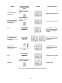
1
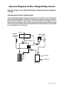
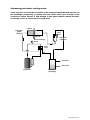
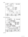
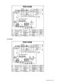
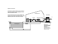
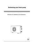
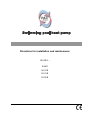
Directions for installation and maintenance
MODEL :
KS8R
KS12R
KS15R
KS20R
Sommaire
1. Introduction
………………….…………………………….……..………….p3
2. Caution …………………………………………………….………………….…..p3
3. Delivery control …………………………………………........................p4
4. Delivery control …………………………….………………………………..p4
Technical characteristics
Outside
Inside
General diagram of the refrigerating circuit
Safety and control systems
Electric diagram
5. Installation
……………………….………………………………….......p12
Rules of installation
Hydraulic connections
Electric connections
Procedure of use
6. Water flow and refrigerating circuit pressure........................p16
7. Defrosting ……………………………………………………………………p17
8. Problem solving
………………………………………............p17
9. Error messages and what to do
………………………………..…p18
www.pac-direct.com
1- Introduction
We thank you for having chosen our Heat pump.
This installation and maintenance notice contains the necessary
information to its installation (delivery control, the installation, the
connections) and to its repair. It is a complementary document to the
user’s manual which describes its instructions for use.
We invite you to read it first.
2- Caution
This document is an integral part of the product and it must stay with
the unit.
This Heat pump is exclusively for heating swimming pools.
Any other use not intended and will be considered as dangerous and
unsuitable.
The assembly, the electric connection and the start up must be carried
out by specialized and professional person.
In the interests constant improvement, our products can be modified
without notice, the pictures in this note or the characteristics which
are described are not contractual.
3- Delivery’s control
On delivery, check the condition of packing, in case of damages,
please inform the carrier within 48 hours by registered letter with
acknowledged receipt.
Before any manipulation, check the complete state of the machine.
www.pac-direct.com
Outside:
(For example of model KS12R)
4
5
3
1
2
3
4
5
6
Front panel in lacquered thermo sheet
7
8
Wire pass with stuffing box
Fan protection grid (blowing side)
Lacquered thermo sheet cover
Control panel with folding shutter
Pressure
Fast connectings 1”1/2 water of swimming pool
(with watertightness gasket); input water at bottom
Gilled radiator (evaporator)
2
6
1
Inside:
8
7
(For example of model KS12R)
(sheet cover and panels removed)
8
Gilled radiator (evaporator)
9
Fan
13
10
Compressor
11
3 way valve (automatic selection of the
expansion capillaries)
12
Connection of the flow detector
13
High and low pressure switches
14
4 way valve
15
Exchanger (condensor)
16
Defrosting sensor
17
Temperature sensor of swimming pool water
18
Access to the flowswitch
9
10
11
12
17
14
15
18
16
www.pac-direct.com
Exploded View:
21
20
19
18
17
16
15
14
13
12
11
10
9
8
7
6
5
4
3
2
1
(For example of model KS12R)
Elect rical Box
Terminal
Flow detect or
Separated manomet er
Filling gas valve
Right Rear Board
Power Cord
Right side board
Titanium and PVC Heat Exchanger
Copper pipe
Four Way Valve
Low Pressure switche
High Pressure switche
Compressor
Four Way Valve
Copper Pipe
Verge Board
Verge Board Polyfoam
Control Panel
Control Panel Cover
Front Panel
1
1
1
1
1
1
1
1
1
1
1
1
1
1
1
1
1
1
1
1
1
36
35
34
33
32
31
30
29
28
27
26
25
24
23
22
1
1
1
1
1
1
1
1
1
1
1
1
1
1
1
Fan
Fan Mot or
Motor Bracket
Top Cover
Lef t Net
Lef t carriage
Condenser Top Polyfoam
Condenser
Rear Net
Defrost Sensor
Feet
Chassis
Compressor Capacitor
Motor Capacit or
Circuit Board
www.pac-direct.com
General diagram of the refrigerating circuit
The heat pump is reversible allowing the swimming-pool’s heating or
cooling:
Swimming-pool water heating mode:
The cold and liquid refrigerant fluid absorbs the heat contained in the air through the
evaporator (gilled radiator), in which it is vaporizing; it is then put under pressure and
heated by the compressor which sends it in the condenser (exchanger) where it
loses its heat (in giving it to the water of swimming pool) and comes back in liquid
state; it loses its pressure and cools in the expansion capillaries before turning back
to the evaporator for a new cycle.
Hot air
Evaporator
(gilled
radiator)
3 way
valve
Cold air
Expansion
capillary
Pressure and gas
intake
4 way valve
Hot water
Cold water
Compressor
Condenser
(exchanger)
www.pac-direct.com
Swimming-pool water cooling mode:
The 4 way valve reverses the circulation of the refrigerant fluid; the fluid vaporizes in
the exchanger (evaporator) in getting the heat of the water, goes through in the
compressor which reheats it and through in the gilled radiator (which becomes
condenser) where it comes back to liquid state.
Cold air
Evaporator
(gilled
radiator)
3way
valve
Hot air
Expansion
capillaries
Pressure and gas
intake
4 way
valve
Cold water
Heat water
Compressor
Evaporator
(exchanger)
www.pac-direct.com
Safety and control systems
The heat pump is fitted with:
De 3 safety features :
•
•
•
A temperature sensor in the evaporator, starting the
defrosting operation.
An ambient temperature sensor ensuring the cut out of the
heat pump when the temperature of the external air goes
below 7°C (factory settings). The normal cycle restarts when the
outside temperature goes up to 12°C (factory settings); See the
USER MANUAL for changing the factory settings.
A temperature sensor placed on the exchanger, ensuring the cut
out of the heat pump when the temperature of the water reaches the
required temperature. The normal cycle restarts when the
temperature in the exchanger goes down to a temperature lower of
2°C than this required.
With 4 safety systems:
•
•
•
•
A water flow detector placed at the entry of the exchanger
A high pressure gas circuit breaker, a low pressure gas circuit
breaker
An outlet compressor temperature sensor
Integrated to the card, a magnetic ammeter/circuit breaker on
the compressor.
If a defect occurs on one of these systems (defective system, off-line
or abnormal measured value) a error message appears on the display
screen; see the paragraph “Error codes and what to do” of this note.
Caution: the removal or bypass of these safety systems negates the
guarantee.
Electric diagram
www.pac-direct.com
KS8R
KS12R (Single-phase)
KS150R
www.pac-direct.com
KS200R
www.pac-direct.com
5- Installation
Rules of installation:
Electric and hydraulic connections must be carried out according to standards in
effect (NF C 15 100, CE I 364).
The machine must be installed outside.
The machine must be fitted on its anti vibratory studs, leval and on a concrete base
this base must have a sufficient height to prevent any entry of water into the bottom
of the machine. Height must be adjusted to fit the connector collecting the
condensates.
All obstacles such as wall and vegetation must be separated from the machine as
indicated on the diagram below.
Exhaust
side
0,3 m mini
0,5 m mini
Blowing
2,5 m mini
side
0,5 m mini
Do not to install the Heat pump in a confined place (the fan would recycle its air and
the Heat pump will have reduced performance).
Other precautions of installation:
- Avoid directing blowing against dominant winds.
- If the machine is intended to be used in winter, put it in a place protected from the
falls of snow.
- The machine must be able to be supervised in order that children do not play nearby
www.pac-direct.com
Hydraulic connections:
Connection is carried out with a by-pass located on
the circuit of filtration, upstream appliances of the
chemical treatment of water.
Technical room
Heat Pump
Connect intake/outlet water PVC pipes DN50 to the
openings of the machine in following the inlet / outlet
indications (grease the worms before screwing)
By-pass
Blowing
Chemical treatment
Filter
Swimming-Pool
Drain of the
condensates: insert
the plastic elbow in
the hole of
evacuation of the
bottom and connect
the pipe if need.
Electric connections:
CAUTION: before connecting the machine, make sure that the power supply is
disconnected.
The electric installation must be carried out by an experienced electrician and the
supply must have differential protection; the installation must be carried out
according to current regulations in the country where the material is installed.
Characteristics of the electric supply:
- 230 V +/- 10%, single-phase current, 50 Hz, or 380 V +/- 10%, three phase current, 50
Hz. (According to the actual model)
- Mode of neutral TT and TN.S; the circuit of heat pump must be connected to an
earth circuit.
Procedure of use
12
Action
Put the heat pump
under tension
Put in circulation the
swimming pool water
into the pipes
Start
Go from heating mode
to cooling mode or
inversely from cooling
to heating
Set the wished
temperature into the
swimming pool
External appliance
or button of heat
pump
Display
Heat pump answer
Engage the circuit
breaker of the heat
pump
Indicate the current hour
Engage the circuit
breaker of pump of
filtration
Indicate the current hour
Press the button
Start between 1 second
and 4 minutes in the last
active mode (heating or
cooling)
ON/OFF
Stop for 4 minutes, reverse
of cycle and restart in a
new mode
Press the button
MODE
Up
and
Down
The heat pump heats or
cools until the required
temperature
adjustable from 10°C to
35°C
Press the button
Stop
ON/OFF
Immediate stop and wait
Use the circuit breaker
of pump of filtration
Complete stop
Switch off
Nota : for the hour setting, see the User Manual.
13
6- Water Flow and refrigerating circuit pressure
After putting into service, adjust the pressure of the refrigerant circuit for
optimal operating of the heat pump, following:
Stage 1:
Access to the seal of the filling gas valve
in removing the rubber cover ; before starting
the Heat Pump, connect the manometer, the
needle must show before starting an
ambient temperature around 20°C, a pressure
from 14 to 16kg/cm².
Stage 2:
Close completely the by pass valve and open the inlet and outlet valves of the
Heat Pump; in these conditions the totality of the water flow goes by the Heat
Pump.
Put the Heat Pump in heating mode, wait for the indicated pressure to
stabilized; the correct setting of the pressure is from 28 to 30 kg/cm²;
In most of cases you do not have to open the by pass valve.
If the stabilized pressure is under 28kg/cm², the progressive opening of the by
pass valve will allow a rise in this pressure.
The adjustment of the by pass valve done, you have in principle no reason to
modify it during the season. See the paragraph “Environment problem” too.
14
7- Defrosting
The defrosting is necessary only in heating mode.
Sequences of the defrosting:
1- Start
The defrosting is engaged if the following conditions occur:
- the defrosting sensor temperature goes down to -9°C
- the compressor runs without stopping for 5 minutes
- the compressor had run totally 45 minutes
2- The compressor and the fan stop
3- After 20 seconds, the 4 way valve shifts
4- One minute after its stop, the compressor starts alone and the
accumulated frost on the gills becomes melting
5- The defrosting stops if one of the following conditions occurs:
- the defrosting operates 20 seconds and the detected temperature
- by the defrost sensor goes up to 7°C.
- the compressor has run for 8 minutes
6- The compressor stops
7- After 1 minute the 4 way valve shifts
8- Two minutes after its stop the compressor and the fan
restart in heating mode.
8 – Environment problem
Under certain external conditions the heat exchanges between the refrigerant and
the water on one hand and between the fluid and the air on the other hand are
insufficient; the consequence is that the refrigerating circuit builds up in pressure
and the compressor consumes more electricity.
The temperature sensors on the compressor outlet and the magnetic circuit breaker
on the compressor power supply protect the compressor from these extreme
conditions; the error messages E 05 or E 06 occur.
The condition causing this situation is as follows:
In heating mode:
- insufficient water flow: close the by-pass valve for increasing the refrigerant
exchange Æ water
In cooling mode:
- too high water flow: open the by pass valve to decrease the water flow and
so the exchange water Æ refrigerant
- insufficient air flow: be sure that the gills of the radiator are not blocked.
Nota: these error codes are likely to occur if temperature of swimming pool water is
high and the ambient air is hot.
15
9 – Error codes and what to do:
This table explains the error codes caused by a defective
regulating component or by a security operation.
Screen and state
of the heat water
pump
E1
The heat pump
continues running
E2
The compressor stops
and after the fan stops
too
E3
The heat pump
continues running
Component
Possible
Intervention
Water temp sensor
Sensor disconnected,
non supplied or
defective
Check the connections, the wires, change
it or replace the electronic card
Ambient air
temperature sensor
Sensor disconnected,
non supplied or
defective
Check the connections, the wires, change
it or replace the electronic card
Oultlet compressor
temperature sensor
E4
Compressor and fan
stop
Defrosting system
E5
Magnetic ammeter
E6
Compressor and fan
stop
Oultlet compressor
temperature sensor
E7
Compressor and fan
stop
Magnetic circuit
breaker
Flow switch
The compressor hums
without starting and
the electric supply
breaks
Starting condenser
of the compressor
E9
High pressure
pressostat
EA
Low pressure
pressostat
Sensor disconnected,
non supplied or
defective
The defrosting is
incomplete and the
automatism decides to
stop the heat pump
The compressor stops 3
times in 24h because of
intensity excess in the
compressor
Oultlet compressor
temperature detected
up to 105°C more than 3
times in 24h
Electric current leak
from the compressor,
from the fan or from an
electrovalve; electric
safety system of the heat
pump
Flow switch
disconnected, non
supplied or defective
The condenser is
defective
Pressostat is
disconnected, or
defective
Pressostat is
disconnected, or
defective
16
Second
reason if the
intervention
is without
effect
Check the connections, the wires, change
it or replace the electronic card
Increase lightly the water flow going into
the heat pump; the effect is to increase the
temperature of the refrigerant in the
evaporator.
Environment problem
See §8
Environment problem
See §8
Switch off the current and call an
electrician for repairing or replacing the
defective component
Check the connections, the wires, change
it or replace the electronic card
Compressor
piston clamped,
Replace the
call a
condenser
refrigerating
engineer
Call a refrigerating engineer who will do
the necessary controls of the circuit
pressure
Call a refrigerating engineer who will do
the necessary controls of the circuit
pressure