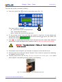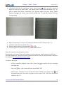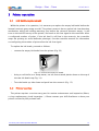
1
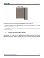
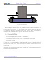
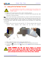
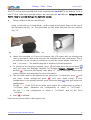
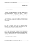
Design • Print • Trace
07/07/2011
Disclaimer
This manual contains instructions for operating the ALE TC18, TC54 and
TC72 print-heads. Read it carefully before performing any manipulation.
All service operations should be undertaken by qualified personnel only.
Contact-us if you need training for our equipment.
All information written in this Operator Manual was correct at the time
indicated in the version table below. However, the continual enhancement of
our products may result in some differences existing between the
information contained in this document and your equipment.
Copyright © 2011 ALE Sarl, all rights reserved. Reproducing this manual in
whole or part without permission is expressly prohibited.
RiX® and TraceX® are registered trademarks of ALE sarl.
All trademarks in this document belong to their respective owners.
Version history:
Date:
Revision:
Modifications:
Author:
22/03/10
First version
11/08/10
2
+TC54
AF/GP
30/08/10
#2.1
Small corrections
AF
06/09/10
#2.2
+"Bottle replacement" section
AF
07/07/2011
#3
+TC18
AF
TC Series Operator Manual
AF
i
Design • Print • Trace
07/07/2011
Contents
Disclaimer
i
Contents
ii
Notes
iii
1 Description
1
1.1 Print-head description
1
1.2 Dimensions
1
1.3 Alarm LED
2
2 Start Up
2.1 On line installation
3
3
2.1.1 Defining the position of the system
3
2.1.2 Installing the system along the conveyor
4
2.1.3 Photocell installation
5
2.1.4 Encoder installation
6
2.2 Inking up for the first time "from dry"
2.3 To enable the prime switch
3 Printer operation
7
13
14
3.1 Ink bottle replacement
14
3.2 Printer service
14
4 Controller usage
15
4.1 Change parameters
15
4.2 Make a message
15
TC Series Operator Manual
ii
Design • Print • Trace
07/07/2011
Notes
TC Series Operator Manual
iii
Design • Print • Trace
07/07/2011
1 Description
1.1
Print-head description
Features:
–
18mm print band with the TC18
–
54mm print band with the TC54
–
72 mm print band with the TC72
–
print-forward only
–
uses ALE 250mL ink bottles
–
304 Stainless steel enclosure
–
2 versions : D25 data cable (to connect with a J-Series controller) or IEEE1394 data
cable (to connect with a K-Series controller)
Alarm
LED
Data connection
Prime switch
250mL
Ink bottle
Fig. 2: 4x M5 mounting holes underneath
print-engine
Fig. 1: TC series print-head front view
On top of the TC print-head is an alarm LED. See 1.3 Alarm LED for information.
Note:
TC72-H uses ALE BOBET7X 250mL bottles; TC18-H and TC54-H use ALE BOB
250mL bottles.
1.2
Dimensions
The main dimensions are given in the following drawing (Fig. 4).
TC series print-heads Operator Manual
1
Design • Print • Trace
1.3
07/07/2011
Alarm LED
Fig. 3: TC18 side dimensions
Fig. 4: TC72 side dimensions
Fig. 5: TC54 side dimensions
Fig. 6: TC Series bottom dimensions with M5 mounting points
TC series print-heads Operator Manual
2
Design • Print • Trace
07/07/2011
There is a red alarm LED on top of the print-head. It starts blinking when the level of
ink is too low in the reservoir, which means that the bottle of ink is empty. Replace it by
following the steps described in 3.1.Ink bottle replacement
After a configured number of prints, if the ink level is still low in the reservoir, the
controller stops the printing (to avoid defective printings). See the controller manual for
information on configuring the number of prints after the ink-low signal.
When the ink low is detected, the print-head sends an alarm signal to the controller,
which can transfer it to an external device such as a PLC. See controller manual for
details.
2 Start Up
2.1
On line installation
2.1.1
Defining the position of the system
After unpacking the printer and checking that the contents correspond to your order
and to the delivery note, the first operation will be to set the position of the print-head
on the conveyor. The correct print-head position can be determined using Codex and
its 3D capabilities (Fig. 7). Please refer to the Codex manual for details.
Fig. 7: CodeX 3D view with a TC72
You must know that the system must be adjusted so that the surfaces to be printed
don't touch the print-head, and are at a maximum distance of 3mm (Fig. 8).
TC series print-heads Operator Manual
3
Design • Print • Trace
07/07/2011
Fig. 8: Maximum printing distance : 3mm
Evaluate, then set precisely the product distance several times before “inking up” the printer
and printing messages ! We strongly recommend fitting product guide rails.
Install the controller in such a way that it is not at a wire distance superior to 1,5m from
the TC print-head (J-Series controller).
Don't hesitate to contact your distributor in case you have any questions regarding the
position of the printer.
2.1.2
Installing the system along the conveyor
Once the correct position of the printer is theoretically determined, take the S062 square
out of the box (Fig. 9) and screw it in the desired position along the conveyor onto a stable
independent floor-stand. Screw the TC print-head to S062, using the 4 M5 holes under the
print-head enclosure (see also packing list). See Fig. 10.
TC series print-heads Operator Manual
4
Design • Print • Trace
Fig. 9: S062 Square
07/07/2011
Fig. 10: Print-head mounting
Due to the risk of vibration, it is not recommended to fix the printer directly onto
the conveyor.
Install the controller and connect it to the print-head using the supplied data cable but
do not power on.
When the final position of the print-head along the conveyor is determined, the next
step is to “ink up” the TC print-head, as it is shipped dry (see next chapter).
2.1.3
Photocell installation
Install the supplied photocell close to, but before the print-head. This will detect the
product just before it passes the print-head nozzles (Fig. 11)
TC series print-heads Operator Manual
5
Design • Print • Trace
07/07/2011
Fig. 11: Photocell position
When installing the photocell ensure that the detection is not confused by reflections, or
by poor light or colour contrast. The two LED lights on the photocell should only light once
as it detects the passage of the product. If this is not the case, adjust the sensitivity by
rotating the little screw either left or right (see manufacturers instructions).
2.1.4
Encoder installation
It is recommended to add an encoder to the system if :
–
the production line has an often varying or automatically varying speed
–
barcodes are printed.
In both cases it is recommended to install the encoder as close as possible from the
printing position of the printer along the conveyor, to minimize the elastic effects of the
conveyor belt.
Information for connecting the encoder to the controller and for operating the encoder can
be found in the controller manual.
TC series print-heads Operator Manual
6
Design • Print • Trace
2.2
07/07/2011
Inking up for the first time "from dry"
It is recommended that the printer is removed from the production line
during this procedure as there is a risk of ink spillage. Fix the printer to a
suitable support.
●
Support the TC print-head to a floor-stand, in printing position.
●
With the controller switched off, connect it to the print-head using the data cable
from the TC series print-head.
Note : the TC print-head can be connected either to a J-Series controller (D25 cable format)
or a Master Pad controller (IEEE1394 cable format). The following procedure describes how
to operate the TC print-head with a J-Series controller. For instructions on how to operate a
TC print-head with a Master Pad controller, please ask your distributor for a Master Pad
user manual.
●
Remove the air pin from the ink tray (Fig. 12). This pin prevents leaks from the
reservoir
during
shipment.
Fig. 12: Remove air pin and
cap
Also
remove
the
cap
from
the
reservoir.
Fig. 13: Place a collecting bucket in front of the print-head
●
Place a collecting bucket in front of the print-head (Fig. 13).
●
For the TC72 OIL version, fit an ALE BOBET7X 250mL ink bottle in the reservoir
●
For the TC54 OIL version or TC18 OIL version, fit an ALE BOB 250mL ink bottle in the
reservoir.
SAFETY WARNING! The inks and solvent cleaners are chemical
products. In the interests of safety, read the Material Safety Data
Sheets carefully before handling the fluids. Always wear protective
gloves and eye protection when in contact with any inks or solvents.
TC series print-heads Operator Manual
7
Design • Print • Trace
07/07/2011
The TC72-H has been specially built to be used with the ALE BOBET7X ink and the TC54-H
and TC18-H have been specially built to be used with the ALE BOB ink. Using any other
fluid is likely to severely damage the hydraulic system.
Fitting a bottle of ink into the reservoir:
●
Using a craft knife (or a sharp blade), cut the round raised plastic dome on the top of
the ink bottle cap (Fig. 14). Turn the bottle up-side down and push into the reservoir
(Fig. 15).
Fig. 14: Cutting the plastic cap of the ink bottle
●
Fig. 15: fitting a bottle
Switch the controller on. From this moment, the LCD screen will run through the
start up procedure. After a few seconds, the controller will emit some beeps. This is
an automatic set up, so there is nothing to do until the screen shows “ Print msg : 01”
and “***no text***”. The default language is English on all new machines.
●
To change to the language required, press
and then press the arrow down
until you select the language required, for example “Langue, Français”. Enter by
pushing
. The screen will display “ Impr. Mess: 01” “Pas de message”. Please report
to the controller documentation for more information.
●
The controller needs to be adjusted to the print-head. To check this, press
you reach “Install settings”and press
until
. LCD says “head config”. If your
configuration is not already selected, press the arrow down
until you reach your
configuration.
For the TC72: If the TC72 has an 80pL print-engine the configuration to select is
"1xT72mm
●
80pL". Otherwise the configuration to select is "1xT72mm".
For the TC54 the configuration to select is "1xT54mm", and for the TC18
"1xT18mm"
Press
to validate.
Then the ink system needs to be purged of air.
TC series print-heads Operator Manual
8
Design • Print • Trace
07/07/2011
To prime the system, proceed as follows :
●
Press the “prime” key
. It leads to the prime menu (Fig. 16).
Fig. 16: J-Series prime menu
This menu offers 3 options:
●
●
–
Jet : primes the circuit at high pressure
–
Test : prints with all nozzles
–
Norm : primes the circuit at low pressure
To ink up the circuit "from dry" the "Jet" prime is used first. On the display the
second line shows:
.Press the arrow left
display now shows
.
Press
to get a "Jet" prime. The
. You should hear the pump “load” (the whirring noise slows down when the
pumps fills in with ink) Repeat this operation until ink jets out of the print-engine.
WARNING : The pump pressure in “inking up” mode is maximum and
ink will jet out!!!
●
Prime twice more using the "Jet" function to remove air from the ink circuit.
●
Prime at least once using the "Norm" function. This is done to remove the remaining
air bubbles from the circuit.
●
Carefully wipe excess ink off (Fig. 17). Do not touch the nozzle plate : it is coated
with a special “non wetting coating” which is self cleaning.
Fig. 17: !! Carefully and gently !! wipe the excess ink
TC series print-heads Operator Manual
9
Design • Print • Trace
●
07/07/2011
Check that all dots are operating : press arrow down
whilst moving a sheet of
paper in front of the print-head. You should print a solid black rectangle (Fig. 18),
with no white lines across. Otherwise (Fig. 19)prime again using the “Norm” option
(Right arrow
in the “Prime” menu) and a bucket (Fig. 13) and check again if all dots
are operating.
Fig. 18: Correct black pad
Fig. 19: Incomplete black pad
●
When the printing is correct, the collecting bucket can be removed (Fig. 13).
●
carefully clean the print-head (Fig. 17).
●
Exit the prime menu of the controller (
●
Set the system for printing back on your production line.
or
).
Prime the system using the prime switch :
Alternatively, you can use the prime switch to prime the print-head instead of using the
controller keyboard. This can be useful if the print-head is too far away from the controller.
See chapter 2.3 To enable the prime switch.
To make a test print :
–
On the controller keypad, press the “arrow up”
to select the test message
(message 00).
–
Press the
key : the screen will then show PRINT OFF.
–
Hold a piece of paper in front of the print-head. Briefly press right arrow
and
simultaneously pass the piece of paper across right to left. The result should be
similar to Fig. 21.
TC series print-heads Operator Manual
10
Design • Print • Trace
07/07/2011
Fig. 20: Successful test message printed with a TC18
Fig. 21: Successful test message printed with a TC72
Fig. 22: Successful test message printed with a TC54
–
It is also possible to make a test print by pressing the "prime switch" shortly
whilst the controller is in "PRINT OFF" mode (see next page).
TC series print-heads Operator Manual
11
Design • Print • Trace
2.3
07/07/2011
To enable the prime switch
you can use the prime switch (see Fig. 1)to prime the print-head instead of using the
controller keyboard. This can be useful if the print-head is too far away from the controller.
To enable the prime switch to work at ANY time:
Press and hold the switch. Wait. LCD will show "ENABLE REMOTE PRIME SWITCH?". Keep
switch pressed and press OK from keypad.
Once the prime switch is activated, you can use it to prime the system or do a test print.
To prime using the prime switch: on the controller keypad press the “prime” key
. If
you press the switch once, you will get a “norm” prime.
To print a "test patch" (all nozzles, Fig. 18) press and hold the switch for a longer time.
TC series print-heads Operator Manual
12
Design • Print • Trace
07/07/2011
3 Printer operation
3.1
Ink bottle replacement
While the printer is in operation, it is necessary to replace the empty ink bottle before the
internal reservoir goes empty as well. The printer reservoir has an optical ink-low detection
mechanism, which will sending warnings just before the reservoir becomes empty : it will
turn on the red LED on top of the printer, and send an ink-low signal to the controller. After
a configured number of prints, if the ink level is still low in the reservoir, the controller
stops the printing (to avoid defective printings). See the controller manual for information
on configuring the number of prints after the ink-low signal.
To replace the ink bottle, proceed as follows:
–
remove the empty ink bottle from the printer (Fig. 23)
Fig. 23: remove the empty ink bottle
–
Using a craft knife (or a sharp blade), cut the round raised plastic dome on the top of
the new ink bottle cap (Fig. 14).
–
3.2
Turn the bottle up-side down and push into the reservoir (Fig. 15).
Printer service
The printer requires a service every year for routine maintenance and inspection (filters,
o-rings replacement, visual inspection...). Please contact your ALE distributor to have your
printer serviced by fully trained staff.
TC series print-heads Operator Manual
13
Design • Print • Trace
07/07/2011
4 Controller usage
4.1
Change parameters
The basic programmable functions of : “language”, “print delay”, “calibrate” (line speed)
and “ink density” are directly accessible via the
key on the keypad. All further functions
can be found by scrolling further down to the sub menus “Print settings”, “Install settings”
and “Other settings”. Please refer to the set up menu diagram for more information
All ALE controllers (either series J, Z or Master Pad) have large memory stores and will
accept a large range of character fonts, barcode formats, images and logos. The procedure
for loading files into the controllers is detailed in the Codex reference manual.
A full explanation of the parameters is detailed in the complete controller manual found
in the included CD. This reference manual has over 300 pages of explanation and advices.
4.2
Make a message
For instructions on how to make a message, please also read the controller's user
manual.
TC series print-heads Operator Manual
14