1
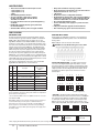
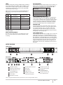
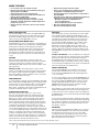
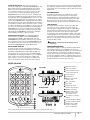
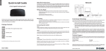
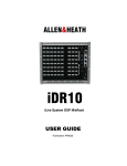
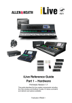
17. The apparatus shall be connected to a mains socket outlet with a
protective earthing connection.
18. Mains plug is used as the disconnect device. It shall remain
readily operable and should not be obstructed during intended
use.
19. WARNING: To prevent injury, this apparatus must be securely
attached to a rack in accordance with the installation instructions.
20. Detailed installation instruction in user manual.
Hear Back PRO User Guide
i
ii
Hear Back PRO User Guide
ELECTROMAGNETIC COMPATIBILITY
This device complies with part 15 of the FCC Rules and the Product Specifications noted on the Declaration of Conformity. Operation is
subject to the following two conditions:
•
this device may not cause harmful interference, and
•
this device must accept any interference received, including interference that may cause undesired operation.
Operation of this unit within significant electromagnetic fields should be avoided.
•
use only shielded interconnecting cables.
WARNING
The Hub unit produces heat while powered, and therefore requires adequate ventilation to ensure the internal temperature stays
within maximum operating temperatures (0° C to 54.5° C, or 32° F to 130° F).
Please ensure that these clearances are met:
•
0.85 inches of clearance on either side of Hub
•
1 inch of clearance in front of Hub
•
11 inches of clearance in back of Hub
Care should be taken so that the Mixer’s ventilation holes remain unblocked, allowing adequate airflow through both sides of
the unit.
If you want to dispose this product, do not mix it with general household waste. There is a separate
collection system for used electronic products in accordance with legislation that requires proper
treatment, recovery and recycling.
Private household in the 25 member states of the EU, in Switzerland and Norway may return their used electronic products free of charge
to designated collection facilities or to a retailer (if you purchase a similar new one).
For countries not mentioned above, please contact your local authorities for a correct method of disposal.
By doing so, you will ensure that your disposed product under goes the necessary treatment, recovery and recycling and thus prevent
potential negative effects on the environment and human health.
DECLARATION OF CONFORMITY
Manufacturer’s Name:
Hear Technologies
Supplementary Information:
Manufacturer’s Address:
991 Discovery Dr.
Huntsville, AL 35806, USA
The product herewith complies with the requirements of the:
Low Voltage Directive 2006/95/EC
EMC Directive 2004/108/EC
RoHS Directive 2002/95/EC
WEEE Directive 2002/96/EC
EC Regulation 278/2009
Declares that the product:
Product Name:
Hear Back PRO
Product Option:
All (requires Class II power adapter
that conforms to the requirements of
EN60065, EN60742, or equivalent.)
Conforms to the following Product Specifications:
Safety:
IEC 60065 -01+Amd 1
EMC:
EN 55022:2010
55024:2010
FCC Part 15
With regard to Directive 2005/32/EC and EC Regulation
1275/2008 of 17 December 2008, this product is designed,
produced, and classified as Professional Audio Equipment
and thus is exempt from this Directive.
Nason Tackett
Senior Design Engineer
Hear Technologies
991 Discovery Drive
Huntsville, AL 35806, USA
Date: August 15, 2014
Hear Back PRO User Guide
iii
A FEW NOTES ABOUT THE SYSTEM
•
Do not share the network with any other devices.
−− High-quality, low-latency audio requires a constant stream of large amounts of data; therefore, other devices on the same network
could compromise the quality of the audio.
•
The system will not link at 10/100 Mbps, as it is designed to work at gigabit speeds.
•
The system is designed to work with suitable CAT6 cable complying with the National authorities (cable with an outer jacket or
sleeving rated VW-1 or better). Note, using low-quality cables may result in the Mixers refusing to link with the Hub.
•
CAT6* cables, used for HBus or going to PRO Mixers, can be run 100 meters (328 feet) with no problems. Note, due to advanced
internal termination techniques, cables used with the PRO series can be run up to 500 feet in ideal conditions (one piece of solid
conductor CAT6* with no breaks or couplings). Utilizing proper punch-down and the correct RJ-45 connectors is key. The more
breaks/connections/couplings in a cable run, the more limited this distance will be. Poor quality cabling will also limit the maximum
distance. Running CAT6* cables alongside AC cables, florescent light fixtures, or computer network wiring will also limit the maximum
distance. It is always preferred to run the Hear Back PRO CAT6* cabling by itself, away from other cabling. ALL cabling should be
electrically tested before use. Contact an expert network professional for assistance with wiring installation.
•
Don’t use those old, gray, flat telephone cables (ISDN cables) as those are not gigabit Ethernet cables.
•
The ground and power rails of the Mixer are totally isolated from the Hub, meaning no more ground loops to worry about.
•
This system is compatible with most off-the-shelf Gigabit PoE+ network switches.
−− Network switch must be POE+ (30 watts) because the Mixer may otherwise periodically lose power at high volumes, due to it
sourcing slightly more power than standard POE switches provide (15 watts).
−− Since a constant stream of data is required for audio, not all network switches will work with this system due to a function known as
EEE (Energy Efficient Ethernet), which restricts the free-flow of data, sending bursts of data instead.
•
Mixer faceplate can be labeled by using a Dry Erase marker, label maker, or by writing on a removable Mixer overlay.
Please note that using permanent markers results in permanent labels!
Network Switches known to WORK
with the Hear Back PRO
•
•
•
D-Link DGS-1008G
Cisco 300 Series
Netgear GS108
Network Switches known to NOT work
with the Hear Back PRO
•
Netgear GS105
*If you’re unsure if EEE is enabled on your Gigabit POE+ network switch, contact the switch’s manufacturer.
FCC STATEMENT
Note: This equipment has been tested and found to comply with the limits for a Class A digital device, pursuant to part 15 of the FCC
Rules. These limits are designed to provide reasonable protection against harmful interference in a commercial installation. This equipment
generates, uses and can radiate radio frequency energy and, if not installed and used in accordance with the instructions, may cause
harmful interference to radio communications. However, there is no guarantee that interference will not occur in a particular installation. If
this equipment does cause harmful interference to radio or television reception, which can be determined by turning the equipment off and
on, the user is encouraged to try to correct the interference by one or more of the following measures:
• Reorient or relocate the receiving antenna.
• Increase the separation between the equipment and receiver.
• Connect the equipment into an outlet on a circuit different from that to which the receiver is connected.
• Consult the dealer or an experienced radio/TV technician for help.
*Cable complying with the National authorities (cable with an outer jacket or sleeving rated VW-1 or better).
iv
Hear Back PRO User Guide
CONTENTS
i
safety instructions
v
table of contents
1
system description
2
hear back PRO hub
2 hub features
2 hub I/O cards: network and analog input
3 hbus
3 input selector switch
3 input metering
3 status indicating hub logo
3 internal fan
3 dual power ports
3 detail diagram
4
hear back PRO mixer
4 mixer features
4 mixer construction
4 status indicating mixer logo
4 volume
4 pan operation
4 stereo link operation
4 aux input
4 preset operation
4 intercom
5 input signal display
5 settings reset operation
5 line outputs
5 headphone amplifier
5 detail diagram
6
connecting and calibration
6 hook-up diagram
7
technical specifications
8
troubleshooting and operating tips
9
system accessories
10
other hear technologies products
11
limited warranty
Hear Back PRO User Guide
v
ADVANTAGES / FEATURES
• Side-mounted card slot on Mixer for
future expansion
• Large master knob controls overall main mix,
AUX, and intercom levels independently
• Volume and panning control of all
16 channels
This is it – the simplest, most affordable digital
solution to get everyone the mix they need to perform
their best. This new system platform is completely
modular and infinitely expandable, which means it is
the last personal monitoring system you’ll ever need.
Introducing the latest addition to the
Hear Technologies family – Hear Back PRO.
With this system, there is no learning curve. Whether or not
you’ve ever used a personal monitor mixer, the simple layout
of this powerful system makes getting the right mix a quick
and effortless experience. Based in Gigabit Ethernet, this
framework paves the way for an impressive range of future
possibilities.
The Hear Back PRO System: Hub & Mixers
• Direct and immediate visual feedback
of all 16 channels
• Up to 8 pairs of stereo-linked channels
• Support for sampling rates up to 192 kHz
• Selectable XLR or 1/8” Mixer AUX input
• Built-in intercom broadcasts the AUX source
(mic, MP3 player, click, etc.)
• Intercom auto adjusts its own level
so even the quietest message never goes
unheard
• Modular I/O Hub card system lets you
customize the system to match your
configuration, and can adapt to your needs
• Supports secondary power supply to provide
redundancy and power to up to32 Mixers
The Hear Back PRO system consists of two main
components: the Hub and the Mixer. The modular Hub
consists of four card slots, which can be populated with any
configuration of input and/or output cards to fit your exact
needs. Each Hub has the ability to supply signal and power
to as many as 32 Mixers (8 per Network Card), each over
a single standard CAT6* cable. And with the built-in HBus
In/Out ports, multiple Hubs can be daisy-chained together,
allowing for truly unlimited system expansion.
• USB port on Hub makes updating firmware
for future features and upgrades a simple
drag-and-drop operation
The standard Hub (included in the “4-pack”) comes preloaded with one Network Card and two 8-channel Analog
Input Cards which can accept input signals from an audio
mixer via auxiliary, matrix, monitor, and/or direct outputs.
– Instantly store and recall presets from
memory with the push of a button
• Status indicating logos on Hub and Mixers
make it easy to detect and diagnose
problems, should they arise
• Write session info and channel settings
on storable Mixer overlays for an unlimited
number of presets
– Most recent configuration is saved, even
after power-down
*Cable complying with the National authorities (cable with an outer jacket or sleeving rated VW-1 or better).
Hear Back PRO User Guide
1
HUB FEATURES
• Three switch selectable 16-channel input sources:
– Input A (Slots 1 & 2)
– Input B (Slots 3 & 4)
– HBus
• 24-bit Delta-Sigma A/D converters
• Six user-selectable sample rates, indicated
by LEDs: 44.1 kHz, 48 kHz, 88.2 kHz, 96 kHz,
176.4 kHz, and 192 kHz
• Less than .25 milliseconds total system delay (latency)
at 192 kHz
• 16 RGB LEDs intuitively display signal / peak levels
for channel metering
• Standard CAT6* delivers power and signals to Mixers
• Daisy-chain via HBus for very large systems
• Quiet, temperature-controlled fan (only runs when internal
temperature reaches 43° C or 110° F)
• 1 RU chassis
• Modular I/O card-slot configurable mainframe
• Gigabit Ethernet network fabric, with enough bandwidth to
support up to 128 channels of audio at 192/176.4 KHz, 256
channels at 96/88.2 KHz, or 512 channels at 48/44.1 KHz
• 48 volt Power Over Ethernet supply
• Port for redundant power supply (or to power more than
16 Mixers)
• USB port for firmware upgrades and future features
• Error indicating logo glows red should a fault arise
HUB I/O CARDS
NETWORK CARD
ANALOG INPUT CARD
A network card must first be inserted into the Hub’s card slot
4 to transmit power, ground, and audio to Mixers via standard
CAT6* cables. Each network card can support use of up to
eight Mixers simultaneously. Additional Mixers can be used by
inserting a second, third, or even fourth network card into card
slots 3, 2, and 1, respectively. However, to power more than two
network cards (or more than 16 Mixers), an additional power
supply is required. The first two network cards in slots 3 and 4
will receive power if a power supply is present in either power
port; the second two network cards in slots 1 and 2 will only
receive power if a power supply is present in both power ports.
Additionally, a second power supply serves as redundant power
to slots 3 and 4 in the case that one power supply were to fail. A
yellow LED under each power port indicates the presence of 48
volts, even when the Hub is powered off.
Analog inputs are fully balanced and are connected using a
standard DA-88 style Analog cable, such as the Hear Back
Analog cable.
The network card’s RJ45 pin-outs are the same as standard
gigabit Ethernet RJ45 pin-outs, as shown below:
Pin
Pair
1
A+
Description
Power over Ethernet (PoE) 48v**
Suggested Termination
Color Scheme
(568B)***
white/orange
2
A-
Power over Ethernet (PoE) 48v**
orange
3
B+
Power over Ethernet (PoE) GND**
white/green
4
C+
blue
5
C-
white/blue
6
B-
7
D+
Power over Ethernet (PoE) GND**
white/brown
8
D-
brown
DB25 cable pin-outs are wired as shown below:
!
SELECTING SAMPLE RATE – The Analog input card lets
users select the digital sampling rate they wish to convert
their analog audio to via three jumpers located directly under
the Hear Technologies logo on the Analog card circuit board.
Jumper positions can be configured as shown below, where
the blacked-out boxes represent an electrical connection
between pins:
A
***Color Scheme 568A is also acceptable, but do not crossover
from 568A to 568B.
Each Mixer output on the network card has a power supervisor
circuit that will only power the port if a valid PoE device is
detected. In the event of a shorted cable or broken Mixer, the
power supervisor circuit will disconnect the load, permitting
other Mixers to function while protecting the power supply from
the faulty output.
B
A
B
96 kHz
1
*Cable complying with the National authorities (cable with an outer jacket or sleeving rated VW-1 or better).
Hear Back PRO User Guide
A
C
B
C
48 kHz
A
B
A
B
C
88.2 kHz
C
176.4 kHz
A
B
C
192 kHz
(default configuration)
-10dB PAD – The Analog input card provides 2 jumpers per
channel (16 total) that can be removed to achieve a -10dB pad
per channel. These jumpers are labeled 1-8 (corresponding
to each input channel), and located one inch away from the
DB-25 connector. So, in this example, input channels 1 & 4
will be reduced by 10dB, while input channels 2 & 3 are at 0dB:
LEGEND
2
C
44.1 kHz
green
**Gigabit PoE uses a transformer on the data pairs to allow
power and data to share the same pairs similar to how phantom
power works on microphones.
CAUTION: Use only DA-88 Analog. Do not use TDIF.
2
No Jumper
Connected
3
4
Jumper
Connected
HBUS
INPUT METERING
The HBus permits daisy-chaining of multiple Hubs up to 500 feet
apart using the HBus input and HBus output. This HBus is great
for inter-studio or stage-to-stage connections, as well as daisychaining for very large systems. Use Hear Technologies CAT6*
cables available in 50 foot length.
The Hub features a unique input metering circuit consisting of one
LED for each of the 16 input channels. Each LED provides four
visual levels that correspond color to signal strength in dBu:
Signal Strength
HBus RJ45 pin-outs are the same as standard gigabit Ethernet
RJ45 pin-outs, only without power. The pin-outs are wired as
shown below:
Suggested Termination
Color Scheme (568B)****
Description
Color
-36 dBu to
-18 dBu
RMS
blue
-18 dBu to
0 dBu
RMS
green
0 dBu to +17.5 dBu
RMS
yellow
Peak
red
+17.5 dBu (clip)
Pin
Pair
1
A+
Bidirectional Data Pair A
white/orange
2
A-
Bidirectional Data Pair A
orange
3
B+
Bidirectional Data Pair B
white/green
4
C+
Bidirectional Data Pair C
blue
5
C-
Bidirectional Data Pair C
white/blue
The illuminated logo serves as an indicator for several purposes.
Under normal conditions, the logo will be blue, indicating valid
clock is present (could be internal or external). A red logo indicates
no valid clock is present. If the logo is blinking red, this typically
indicates a temperature problem, but could indicate something
else. Refer to troubleshooting section for detailed information.
6
B-
Bidirectional Data Pair B
green
INTERNAL FAN
7
D+
Bidirectional Data Pair D
white/brown
8
D-
Bidirectional Data Pair D
brown
****Color Scheme 568A is also acceptable, but do not crossover
from 568A to 568B.
The internal temperature-controlled fan operates whenever the
internal temperature reaches 43° C or 110° F. In studio or indoor
use, the fan should rarely come on. The Hub should be rack
mounted away from high temperature devices such as power
amplifiers. Please ensure our recommended clearances listed at
the beginning of this manual are met.
INPUT SELECTOR SWITCH
DUAL POWER PORTS
STATUS INDICATING HUB LOGO
The input selector switch gives the user a simple way to select
any one of the three input sources without a patch bay, router,
or rewiring.
The Hub supports two external power supplies. The second power
supply serves two purposes: to provide redundancy in case of
power failure, and to power more than two network cards (greater
than 16 Mixers) in a single Hub. On the front of the Hub, an LED
directly above the power switch will be lit if two power supplies are
present. This provides an easy way to know if one of the power
supplies has failed. On the back of the Hub, an LED is present
directly under each power port, and will be lit if power is present
at that port.
DETAIL DIAGRAM
FRONT PANEL
1
2
3
4
5
REAR PANEL
150W
6
150W
7
8
9
10
11
12
1
LED Status Indicator
7
Secondary 48V Power Input
2
Sample Rate LED Indicators
8
HBus Input
3
Audio Input Channels 1-16
Level LED Metering
9
HBus Output
4
Input Selector Switch
5
Power Switch
6
Main 48V Power Input
10
USB Connection
11
Card Slot 1 (shown with
8-channel Analog Input)
13
14
12
Card Slot 2 (shown with
8-channel Analog Input)
13
Card Slot 3
(shown unpopulated)
14
Card Slot 4 (shown with
8-port Network Card)
*Cable complying with the National authorities (cable with an outer jacket or sleeving rated VW-1 or better).
Hear Back PRO User Guide
3
MIXER FEATURES
• Local control of up to 18 channels of audio
• Receive power and audio over one Ethernet cable, up to
500’ from Hub to each Mixer
• Side-mounted card slot for future expansion
• Large master knob controls overall main mix, AUX, and
intercom levels independently
• 24-bit D/A and A/D delta-sigma converters
• Error indicating logo glows red to indicate a problem,
and flashes red when headphone amplifier temperature
reaches 100° C (212° F)
• Volume / panning / stereo link control of all 16 channels
of audio
• Balanced mono/stereo, line level outputs
• Store up to 4 recallable presets, while most recent
configuration is remembered after power-down
• Intercom feature allows communication to anyone with a
Hear Back Mixer
• Selectable 1/8 inch TRS stereo unbalanced and XLR mono
balanced (with 15v phantom power) AUX inputs:
– Microphone input for crowd/ambiance mic,
or for use with intercom
– Drum module/metronome or local mix input
• One 1/8 inch TRS headphone output
• One 1/4 inch TRS headphone output
MIXER CONSTRUCTION
AUX INPUT
The Hear Back PRO is constructed of UV-stabilized ABS and
has a built-in mic stand mount. The cable strain relief channel
(molded into the Mixer) greatly reduces stress on the CAT6*
cable connectors and the Mixer RJ45 connector.
STATUS INDICATING MIXER LOGO
The illuminated logo serves as an indicator for several purposes.
Under normal conditions, the logo will be blue, indicating digital
audio packets are being received. A purple logo indicates
audio packets are being dropped, and a red logo indicates no
valid packets are being received. If the logo is blinking red,
this indicates the headphone amplifier has overheated. Check
the troubleshooting section if any color other than a blue logo
occurs.
VOLUME
Each channel knob, by default, controls the volume of its
respective channel within the mix. The master knob, by default,
controls the volume of the overall mix. Volume operation is
indicated by blue LEDs. Volume scales from 0% to 100%, left to
right, respectively.
MASTER VOLUME – The master volume is used to set the
volume of the headphones and the line outputs. When using the
line outputs in conjunction with the headphones, optimize the
mix for the headphones and then adjust the device connected to
the line outputs to balance the gain.
PAN OPERATION
To control panning of channels, press the PAN button. The PAN
button and channel knob LEDs will turn green to indicate that the
channel knobs now control panning position of the audio within
the stereo field. To return to volume control, press the PAN
button again, or wait 30 seconds from the last adjustment for the
system to automatically return to volume control.
STEREO LINK OPERATION
Each audio channel comes from a mono source, and is
therefore center-panned by default. To quickly hard-pan two
channels left and right to create a stereo pair, hold the PAN
button for 3 seconds to enter the stereo link control interface.
The PAN button and channel knobs will blink green. Move a
knob to toggle that channel, and its adjacent channel, between
mono and stereo-linked. Notice the panning position jump from
center-panned to hard-panned. This operation can only be
performed on adjacent pairs of channels. Therefore, channel 1
can only be linked with channel 2, channel 3 with channel 4, and
so on. Press the PAN button again to exit the stereo link control
interface, or wait 30 seconds from the last adjustment for the
system to automatically return to volume control. Upon linking
channels, the volume of the right channel is set according to the
volume of the left channel. Volume adjustments to either stereolinked channel now effects both channels in unison.
The auxiliary input connections provided are one 1/8 inch TRS
stereo unbalanced input optimized for 0 dBu input level, and
one XLR mono balanced input optimized for -42 dBu input level,
selectable via the switch located adjacent to the connections.
The inputs provide another mono or stereo-mixed channel to
be inserted into the Mixer. Examples of use would be a drum
machine click track into the drummer’s Mixer, or a crowd/
ambient mic in everyone’s Mixer (which can double as the
intercom mic). Another application would be a stereo mix from
a guitar or keyboard local mix from another Hear Back or Hear
Back PRO Mixer, creating a total of 18 channels controlled from
your Mixer.
AUX INPUT OPERATION – Press the AUX button to change the
function of the master knob to control the volume of the auxiliary
input in the mix. Once pressed, the AUX button and master
knob LEDs will turn red to indicate this function is active. Press
the AUX button again to exit auxiliary volume control, or wait 30
seconds from the last adjustment for the system to automatically
return the master knob to its default function.
PRESET OPERATION
The Hear Back PRO Mixer has the ability to store up to four
system states in internal memory for easy session settings
recall. Pressing the PRESET button will step through presets
1 – 4, one at a time.
To save current settings to a preset, hold the PRESET button for
2 seconds until the LED under the preset number rapidly blinks,
and continue holding the PRESET button for 3 more seconds
to begin stepping through preset memory slots. Release the
PRESET button when the desired preset number is rapidly
blinking to save to that preset memory slot.
Upon making any control change while using a preset, the preset
number will slowly blink to let you know your new settings have
not been saved. To save the changes to the preset, simply hold
the PRESET button for 2 seconds until the preset number rapidly
blink, then release.
To reset a preset’s parameters back to default (all volume at 0%,
all channels center-panned, all stereo-linked channels unlinked),
first complete the settings reset operation (discussed later in this
manual), then complete the normal steps listed above to save
the settings to a preset.
INTERCOM
The intercom function transmits the AUX IN source to everyone
with a Hear Back PRO Mixer on the same network. By default,
the input gain for the intercom source is set to 75%. When
receiving audio from another Mixer, the intercom has an auto
gain feature that automatically adjusts the incoming signal so
that you’ll always hear it over your mix.
*Cable complying with the National authorities (cable with an outer jacket or sleeving rated VW-1 or better).
4
Hear Back PRO User Guide
INTERCOM OPERATION –To broadcast your intercom
momentarily, simply press and hold the INTERCOM button. The
button and the master knob LEDs will light up red to indicate
that the intercom is broadcasting, and that the master knob
now controls the input gain for your intercom source. To latch
your intercom for a continuous broadcast, rapidly push the
INTERCOM button three times in succession. The button and
the master knob LEDs will stay red to indicate that the intercom
is broadcasting. Press the INTERCOM button once more to stop
continuous broadcast and return the master knob to its original
function. The INTERCOM button will rapidly blink red to indicate
that a broadcast from another Hear Back PRO is currently being
received. Only one Mixer is able to broadcast at a time, so while
one Mixer is broadcasting, all other Mixers on the same network
are “locked out” from broadcasting until the transmitting Mixer’s
INTERCOM button is released or un-latched. If another Mixer
is broadcasting and you wish to overtake the intercom, simply
triple-tapping the INTERCOM button will stop the other Mixer
from transmitting, latching your intercom instead.
this mode; however, the level indicator will only be shown briefly
after making an adjustment, before returning to displaying input
signal activity. Press the AUX button again to exit the input signal
display mode.
SETTINGS RESET
To quickly reset all volume to 0%, unlink all stereo-linked
channels, and move any panning back to center position,
simultaneously press and hold the PAN and AUX button for 1
second until all of the channel knob and master knob’s LEDs
blink. This restores the current session settings back to its
default “blank slate” position, but keeps all saved presets intact.
LINE OUTPUTS
Two balanced 1/4 inch TRS line outputs are provided. The
left operates as a mono output for sub woofers and mono
devices if nothing is plugged into the right line output. When a
1/4 inch plug is inserted into the right output, the line outputs
operate in a normal stereo mode. The line outputs may be
used simultaneously with the headphone outputs, and are both
controlled with the master volume knob. In the event of ground
loops when connecting the Mixer line outputs to other devices
that have an earth ground, it may become necessary to lift the
shield at the Mixer outputs.
DISABLING THE INTERCOM – To completely disable the
intercom function on a Mixer, hold the INTERCOM button
while plugging in the CAT6* cable until the PAN, AUX, and
INTERCOM buttons blink rapidly to indicate you have entered
the configuration interface. Pressing the INTERCOM button will
now toggle the intercom on and off. To save the settings, press
and hold the INTERCOM button until the Mixer reboots.
!
NEVER lift or disconnect the AC safety ground of
any device.
HEADPHONE AMPLIFIER
INPUT SIGNAL DISPLAY
The headphone amplifier outputs are paralleled outputs. When
using multiple headsets, the total impedance should not go
below 16 ohms. The headphone amplifiers are very powerful and
can easily damage in-ear transducers, headphones, and your
hearing; exercise great care in adjusting the master volume. At
32 ohms, the amplifier is capable of sustaining 2 watts of power
per ear! The amplifiers are short circuit protected, and will cause
the status indicator logo to blink red if overheated.
To easily see which channels have signal present without
having to turn up each channel individually, press and hold the
AUX button until the AUX button begins blinking rapidly. If a
signal is detected on a channel, the channel’s LEDs will light
up. Additionally, the master knob’s LEDs act as an overall RMS
meter, showing you how much headroom is available. This
makes it easy to see how close the Mixer is to clipping. Note
that you are still able to adjust channel and master volume in
DETAIL DIAGRAM
1
1 LED Status Indicator
TOP PANEL
2 LED Level Indicators
3 Volume/Pan Control Knob
for Each Audio Channel
4 “Intercom” Button
2
15V PHANTOM
STEREO
LINE
5 “Preset” Button
6 “Master” Control Knob
MIC
AUX IN
(Volume / Aux)
7 “Aux” Input Button
3
9
10
8 “Pan” Button
11
9 Auxiliary 1/8” Stereo
Unbalanced Audio Input
BOTTOM PANEL
10 Auxiliary Input Switch
11 Auxiliary Balanced XLR
Microphone Input with
15V Phantom Power
12 1/4” Left/Mono and Right
LINE OUT
(BAL)
4
LEFT/MONOR
Outputs
IGHT
13 1/8” TRS Headphone Output
5
6
7
14 1/4” TRS Headphone Output
12 13 14
8
15
15 Gigabit Ethernet (GbE)
Connection with PoE+
(Power over Ethernet)
*Cable complying with the National authorities (cable with an outer jacket or sleeving rated VW-1 or better).
Hear Back PRO User Guide
5
HEAR BACK PRO CONNECTING AND CALIBRATION
1.
Connect the appropriate input(s), as shown in the
hook-up diagram below and select the desired input using
the front panel switch. Connect Hear Back PRO Mixers to
the network card outputs using CAT6* cables and set all
Mixer channel and master volume levels to 0%. Connect
the headphones, in-ear monitors, and/or line outputs for
connecting to wireless in-ear systems, powered monitors,
or other devices requiring line-level inputs.
4.
Mixer Adjustment: Once you have the signals optimized,
turn the master volume up to about 10 o’clock and then
raise each channel’s volume up to a comfortable level.
Avoid adjusting the master volume too high and running
the inputs too low. If you wish to stereo-link any channels,
enter the stereo-link control interface and toggle them on.
If you wish to pan any mono channels within the stereo
field, press the PAN button to make adjustments.
2.
Turn on Hub power.
5.
3.
Adjust the level at the input source (DAW, mixer, etc.)
until the red clip LED’s on the Hub just come on and then
reduce the levels on the input source until you have a
“green” LED. NOTE: Adjust the source for as much signal
into the Hub as possible without clipping. Higher input
levels improve signal-to-noise and dynamic range. If you
are unable to adjust your source without overdriving the
Hear Back PRO system, follow the “-10dB Pad” instructions
on page 2 to achieve and extra 10db of headroom.
Remember, higher input levels improve signal-to-noise and
dynamic range.
AUX IN Adjustment: If using an auxiliary input, connect
it to the Mixer via the appropriate “LINE” or “MIC” input.
Select the appropriate input via the “AUX IN” selector
switch. If possible, adjust the input source for maximum
volume without clipping. Press the “AUX” button to turn
the “Master” knob LEDs “red” and slowly turn the “Master”
knob to a comfortable level. Press the “AUX” button
again to exit auxiliary volume control.
Now enjoy personal monitoring at its best and have fun!
! WARNING
• The Hear Back PRO is capable of driving most
headphones to extreme levels that can damage
your HEARING!
• ALWAYS turn down the Mixer “Master” volume
down before putting on in-ear headsets or
headphones.
HOOK-UP DIAGRAM
*Cable complying with the National authorities (cable with an outer jacket or sleeving rated VW-1 or better).
6
Hear Back PRO User Guide
TECHNICAL SPECIFICATIONS
Mixer Aux Input
Line Input Configuration/Impedance:
Line Input Level:
Mic Input Configuration/Impedance:
Mic Input Level:
1/8” Stereo, unbalanced, 10K ohms typical
0 dBu optimal, +18 dBu max
XLR Mono, balanced, 150 ohms typical, 150 Hz high pass
-42 dBu optimal, -30 dBu max
Mixer Headphone Power
Load Impedance:
8 Ohms:
16 Ohms:
25 Ohms:
32 Ohms:
50 Ohms:
100 Ohms:
200 Ohms:
600 Ohms:
Inter Modulation Distortion:
THD less than 0.01%*
1.2W*
*THD AT 8 Ohms = 0.015% typical
1.6 W
2.0 W
1.8 W
1.5 W
1.1 W
500 mW
220 mW
Typically less than 0.03%
THD less than 0.1%
1.5 W
1.8 W
2.2 W
2.0 W
1.6 W
1.2 mW
650 mW
250 mW
Mixer Line Output
Frequency Response:
THD+N:
Inter Modulation Distortion:
Crosstalk:
Propagation Delay:
20 Hz to 20 KHz, +/-0.15 dB
0.004% typical at 1 KHz, +15 dBu
0.008% typical, 20 Hz – 20 KHz, +4 dBu
0.02% typical at +4 dBu, 60 Hz/7 KHz
Less than -93 dBu @ 1 KHz
Less than 0.38 mSec @ 192 kHz sample rate
System Noise Performance
Noise, A-Weighted:
Dynamic Range:
-93 dBu @ 192 kHz sample rate
117 dB typical
System I/O
Hub Line In, Analog:
Hub Maximum Input Level, Analog:
Hub HBus In, Out:
Hub USB Port:
Hub Card Slots (4x):
Mixer to Hub Connection:
Mixer Headphone Out:
Mixer Line Out:
Mixer Max Output Level, Analog:
Mixer Aux Input:
Mixer Card Slot:
16 Balanced inputs on 2x DB-25 female (DA-88 pinout)
+2dBu with analog card pad jumpers populated, +12dBu with jumpers removed
8-pin RJ45 jack (standard Ethernet pinout)
USB 2.0 (for firmware updates)
Each slot can accept an analog or digital input card, output card, or 8-port Mixer network card
8-pin RJ45 jack (8x Mixer connections per network card)
1x TRS 1/4” and 1x 1/8” unbalanced stereo
TRS 1/4” balanced (2 connections: left/mono, right)
+24 dBu (mixed output)
TRS 1/8” unbalanced stereo and XLR balanced mono (with 15 volts phantom power)
For future digital or analog input/output expansion capabilities or side-car add-on
Physical, Mixer
Size:
Unit Weight:
Mounting:
9.5” (241 mm) H x 5.95” (152 mm) W x 2.71” (7.62 mm) D
1.6 lb. (0.72 kg)
Standard mic stand (5/8” 27 threads per inch) or desk mounted
Physical, Hub
Size:
Unit Weight:
Mounting:
1.75” (45 mm) H x 19” (482 mm) W x 8.5” (216 mm) D
6.3 lb. (2.8 kg)
Standard rack mount, 1 RU
Power
Hub Power Requirements:
Mixer Power Requirements:
External Power Supply Requirements:
48VDC, 150 Watts (each external power supply powers up to 16 Mixers)***
Power over Ethernet (PoE) 36–52 volts DC, 15 Watts max provided by Hub
through CAT6** network cabling
Input Voltage: 90VAC to 264VAC 50/60Hz
Cabling, Mixers and HBus
CAT6** cables used for Mixers or for HBus can be run up to 500 feet in ideal conditions (one piece of solid conductor CAT6 with no breaks or
couplings). The more breaks/connections/couplings in a cable run, the more limited this distance will be. Poor quality cabling will also limit the
maximum distance.
Note: 0 dBu = 0.775 Vrms.
**Cable complying with the National authorities (cable with an outer jacket or sleeving rated VW-1 or better).
Specifications and features subject to change without notice. ***Hub is capable of powering up to 32 Mixers with an additional power supply.
Hear Back PRO User Guide
7
TROUBLESHOOTING AND OPERATING TIPS
*Note: Some problems require you to refer to the A-B-C-D error code LEDs below the HBus ports on back of Hub.
No Audio Output
• Verify the Hub is powered on.
• Check input connections.
• Make sure input selector switch is in the proper position for your audio source – HBus, input A (slots 1 & 2), or
input B (slots 3 & 4).
• Verify the status-indicating logo on both the Hub and Mixer are both BLUE.
• Check your headphones, wireless transmitters/receivers, monitor amplifiers, etc., to verify they are functioning
properly.
Hub Logo is solid RED
Refer to the A-B-C-D error code LEDs below the HBus ports on back of Hub:
• If no error code LED is lit:
○○ No clock is present.
○○ If using an Analog Input card:
−− Verify the input selector switch is in the correct position.
−− Verify an Analog Input card is present in either slot 1 (for input A) or slot 3 (for input B).
−− If the problem still persists, please call customer service.
○○ If using any Digital Input card:
−− Verify the digital source is functioning correctly – powered on and sending clock.
−− Verify the input selector switch is in the correct position.
−− Verify the Digital Input card is present in either slot 1 (for input A) or slot 3 (for input B).
−− If the problem still persists, please call customer service.
• If error code LED A, B, or A & B are lit:
○○ An internal problem is present. Please call customer service.
• If error code LED C is lit:
○○ No firmware file can be found on the internal SD card. Connect the Hub to a computer via USB. The Hub will
appear on the computer as a mass storage device named HBPRO. Download the latest firmware file from our
website, and simply drag and drop the file onto the HBPRO, then reboot the Hub.
• If error code LED D is lit – alone or in combination with any other error LEDs:
○○ An internal power problem has occurred. Please call customer service.
Hub Logo is blinking RED
Refer to the A-B-C-D error code LEDs below the HBus ports on back of Hub:
• This is typically an overheating problem – if so, error code LEDs A, B, & C will be lit.
○○ Allow adequate ventilation for Hub as specified in owner’s manual.
• If any other combination of error code LEDs are lit, please contact customer service.
Hub Logo is PURPLE
• Verify that there are not two 16-channel input cards on the same input (e.g. slot 1 & slot 2)
○○ The Hear Back PRO Hub cannot have more than one 16-channel input card on the same input
• If using an off-the-shelf network switch, it might utilize a function known as EEE (Energy Efficient Ethernet).
○○ Attempt to bypass the network switch, making a home run from Hub to Mixer, to verify this is the problem –
if so, try a known good network switch from the list at the beginning of the Hear Back PRO User Guide.
Hub Logo OFF
• Verify power switch is on.
• Verify the Hub is receiving power by checking for a yellow LED beneath the power port on the back of the Hub.
This LED should be lit when the power supply is connected, even with the Hub powered off.
• If the yellow LED is not lit:
○○ Verify the external power supply is the unit provided by Hear Technologies.
○○ Replace external supply with known good unit.
Mixer logo is solid RED
• No audio data is being received.
○○ If an off-the-shelf gigabit switch is being used, the Mixer may not be seeing the Hub clock.
−− Attempt to bypass the network switch, making a home run from Hub to Mixer, to verify this is the problem –
if so, try a known good network switch from the list at the beginning of the Hear Back PRO User Guide.
○○ Check the orange and green LEDs on the Ethernet port of the Mixer and ensure that you see a solid lit orange
LED and a blinking green LED. The lit orange LED indicates that a gigabit Ethernet link is established and the
blinking green LED indicates data is being received.
−− If the orange LED is not lit or it lights intermittently, there is a problem with the cabling between the Mixer
and the Hub. To verify this, use a known good short Ethernet cable to plug the Mixer directly into the Hub. If
the problem still occurs, contact our technical support department.
−− If the mixer works with the short piece of known good Ethernet cable, investigate the cable between the
Hub and the Mixer location.
−− CAT6* cables, used for HBus or going to PRO mixers, can be run 100 meters (328 feet) with no problems.
Note, due to advanced internal termination techniques, cables used with the PRO series can be run up
to 500 feet in ideal conditions (one piece of solid conductor CAT6* with no breaks or couplings). Utilizing
proper punch-down and the correct RJ-45 connectors is key. The more breaks/connections/couplings in a
cable run, the more limited this distance will be. Poor quality cabling will also limit the maximum distance.
−− Running CAT6* cables alongside AC cables, florescent light fixtures, or computer network wiring will also
limit the maximum distance. It is always preferred to run the Hear Back PRO CAT6* cabling by itself, away
from other cabling.
−− ALL cabling should be electrically tested before use. Contact an expert network professional for assistance
with wiring installation.
(Troubleshooting and Operating Tips continued on page 9)
*Cable complying with the National authorities (cable with an outer jacket or sleeving rated VW-1 or better).
8
Hear Back PRO User Guide
Mixer Logo is PURPLE
• Mixer is not receiving all audio packets.
○○ Verify Hear Back network is not accidentally connected to a data network. Do not share the Hear Back PRO
network with any other devices.
○○ Verify all off-the-shelf switches used are indeed rated for gigabit speeds.
○○ If using an off-the-shelf network switch, it might utilize a function known as EEE (Energy Efficient Ethernet).
−− Attempt to bypass the network switch, making a home run from Hub to Mixer, to verify this is the problem.
If so, try a known good network switch from the list at the beginning of the Hear Back PRO User Guide.
Mixer Logo flashes RED
• Internal headphone circuit is overheating.
○○ Check to verify headphone load is stereo (not mono).
○○ Verify 1/4 inch and/or 1/8 inch plug is tip-ring-sleeve (TRS), not tip-sleeve (TS).
○○ Look for shorted cables.
○○ Verify total load is not below 8 ohms per channel.
When I connect a line level
device to the Mixer line
outputs, I hear a buzz.
• Wire TRS outputs using only black (ring -) and red (tip +) wires.
• Disconnect shield at the Mixer and terminate at receiving end only.
• For unbalanced outputs, wire the ring (- black) to the receiving end sleeve and tie the shield at the receiving end
only. Connect the tip (+ red) to the tip at the receiving end.
When I link two mono
channels, the stereo
spread is incorrect.
• Verify the source (mixer, DAW, etc.) has these outputs panned hard left and right.
○○ The pan control of the source determines the stereo spread.
The fan does not operate.
• The fan only runs when power supply temperature reaches 43° C or 110° F.
If you need further assistance, feel free to contact Hear Technologies technical support by phone at +1-256-922-1200 or visit our web site at
http://www.HearTechnologies.com.
SYSTEM ACCESSORIES
AM12 AMBIENT MICROPHONE
MIXER TILT ADAPTER
12 inch condenser gooseneck mic with super
cardioid pattern for use with Hear Back PRO
Mixer as an ambient or intercom microphone.
The Mixer Tilt Adapter is for all Hear Back
Mixers adding a ball joint with 5/8” 27 male
threading to any standard imc stand to get the
perfect angle with 360° rotation and 180° tilt.
The AM12 features 15 volt phantom power,
30Hz – 16kHz frequency response, and
-40db sensitivity.
MICROPHONE STAND ADAPTER
Mount the Hear Back Mixer to the side of any mic stand or
standard music stand using the MSA Mic Stand Adapter.
This clamp-on adjustable width bracket attaches to the built-in
5/8” threaded socket located on the back of the Mixer.
supercardioid pattern
TOTE BACK
CABLES
Hear Technologies offers a variety of quolity cables that work with
your system including CAT5e, CAT6, Optical, Insert and Analog
DA-88 style cables.
CAT5 & CAT6
OPTICAL
INSERT
This soft-side nylon carrying case is perfect for carrying
(8) Hear Back Mixers or (4) Mixers and (1) Hub. Adjustable
dividers allow you the freedom to customize the compartments.
ANALOG
Hear Back PRO User Guide
9
OTHER HEAR TECHNOLOGIES PRODUCTS
• Unlimited system size
• Local control of 8 audio channels (stereo mix and six “more-me’s”)
• ADAT, analog, HearBus inputs are switch-selectable from front panel
• Built-in DSP Limiter with threshold adjustment
• Master Volume
• Stereo AUX In
• Balanced Line-Outputs
• Built-in Mic Stand Mount
• Standard CAT5e power
• Affordable 16 x 12 x 2 x 2 monitor mixer
• 16 Mic/Line inputs each with passive split and 2 stereo and 12 mono level controls
• 16 master outputs each available as analog, ADAT, and HearBus
• Pin 1 lift and Mic phantom power switches
• Dual switch-selectable effects sends
• Stereo Aux inputs
• Channel Inserts
• Four-band EQ with dual sweepable mids
• Talkback with intercom and optional remote control
• High quality UHF Wireless Stereo In-Ear Monitor system
• Available in UA (584 – 608 MHz) and UB (655 – 679 MHz) bands
• 120 digitally selectable UHF channels
• Back-lit LCD display of frequency, audio level, group and channel
• Wireless stereo belt pack allows freedom to move about the stage
• Batteries included
10
Hear Back PRO User Guide
NOTES
NOTES
LIMITED WARRANTY
Hear Technologies warrants the equipment against defects in materials
and labor for a period of one year from the original date of purchase. The
duration of this warranty is limited to claims made to Hear Technologies
within the periods stated with respect to parts and labor from the date of
purchase. During the warranty period, defective equipment will be
replaced or repaired to the general condition as received, at the
discretion of Hear Technologies.
All transportation is the responsibility of the purchaser or owner.
Equipment should be shipped in the original shipping box.
This warranty applies only to defects in materials and workmanship and
does not cover failure or damage due to shipping loss or damage, abuse,
misuse, misapplication, incorrect or varying power line voltages, lack of
proper maintenance, natural disasters, acts of God, or unauthorized
modifications, repairs, or any alterations done without the expressed
written consent by Hear Technologies. Hear Technologies shall not be
liable for any loss of use of the equipment, or consequential damages,
including damages to other parts of the installation in which the
equipment is a part.
Hear Technologies does not make any warranty, express or implied, other
than the warranty contained herein. No agent, representative, or
employee has the authority to increase or alter the liability, obligations,
and terms of this warranty or sale of the equipment. NOTE: It is strongly
recommended that any equipment returned to Hear Technologies be
properly packaged and insured for its full value in case of loss, handling
or shipping damage.
Hear Technologies shall not be responsible for damage or loss of
equipment during shipment.
The following are registered trademarks of Hear Technologies:
Hear Technologies, Hear Back, Control Your Mix, Talk Back, Extreme Extender, Hearbuds, HearBus, and the "Jack" logo.
All names and marks of other companies belong to those respective companies.
21
Hear Back User Guide
Hear Back PRO User Guide
11
©2015 Hear Technologies
03-2015