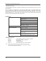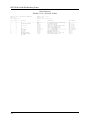
1
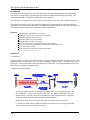
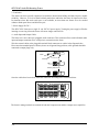
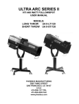
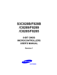
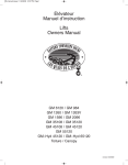
AFR-7814C Audio DA Mounting Frame USER'S MANUAL AFR-7814C-01 AFR-7814C • Audio DA Mounting Frame – User Manual • • • Ross Part Number: AM-7814C-01 Document Issue: 1 Printing Date: March 8, 2000. Printed in Canada. The information contained in this guide is subject to change without notice or obligation. Copyright © 2000 Ross Video Limited. All rights reserved. Contents of this publication may not be reproduced in any form without the written permission of Ross Video Limited. Reproduction or reverse engineering of copyrighted software is prohibited. Notice The material in this guide is furnished for informational use only. It is subject to change without notice and should not be construed as commitment by Ross Video Limited. Ross Video Limited assumes no responsibility or liability for errors or inaccuracies that may appear in this manual. Trademarks • • • is a registered trademark of Ross Video Limited. and RossGear are registered trademarks of Ross ROSS Ross, ROSS, Video Limited. All other product names and any registered and unregistered trademarks mentioned in this guide are used for identification purposes only and remain the exclusive property of their respective owners. Company Address Ross Video Limited 8 John Street Iroquois, Ontario, K0E 1K0 Canada Ross Video Incorporated P.O. Box 880 Ogdensburg, New York USA 13669-0880 General Business Office: (+1) 613 • 652 • 4886 Fax: (+1) 613 • 652 • 4425 Customer Service: (+1) 613 • 652 • 4886 E-mail (Customer Support): [email protected] E-mail (General Information): [email protected] Website: http://www.rossvideo.com After hours emergency: (+1) 613 • 652 • 4886, ext. 333 READ THIS FIRST! Save Time and Avoid Damage! We realize that you will want to start installing your new equipment right away. But, you will save time and avoid costly damage by taking a few moments to review the following helpful information before you proceed. 1. Installation and Cable Connections Before turning the power on, consult the “Installation” section of this manual to obtain specific advice about cable connections, switch settings and jumper configurations. 2. Operation See the “Operation” section for proper use of your new equipment. 3. Calibration All Ross Video Terminal Equipment is factory calibrated. Adjustment of sealed calibration components or any repairs to this unit, are to be performed by an authorized Ross Video technician. Unauthorized repairs will void your Warranty. In Case of Problems If you encounter any problems with the installation of this unit, please call our Customer Service Department at (613) 652-4886, 24 hours a day, 7 days a week. Advice is available, without charge, for the life of this equipment, not just for the warranty period. AM-7814C-01 AFR-7814C Audio DA Mounting Frame Introduction The design of the mounting frame will more than satisfy the most demanding network considerations. The frame is visually attractive and incorporates advanced ventilation and cooling engineering. The mounting frame holds 12 amplifier modules and 2 power supplies. The frame door is completely removable to provide convenient access in any rack installation position. The terminal connectors are of a new smaller pluggable design which allows for individual wiring of each cable prior to connection to the frame. It is important to refer to the table on the rear of the frame to determine the proper connections for the Mono or Stereo amplifiers. Features Accommodates 12 amplifiers in a 2 rack unit Aluminum construction for increased heat dissipation Individual pluggable audio connectors Removable frame door for accessibility Optional module extender for servicing Power switch and fuse is accessible from front of the rack frame PowerLock cord retainer mechanism guards against accidental power loss 5-year transferable warranty Ross frames also accept Leitch* analog audio products *Leitch is a trademark of Leitch Technology Corporation. Installation 1. Mechanical The frame mounts in the rack cabinet by means of four screws through the front mounting flanges. This should normally be sufficient to carry the load, including weight of cables. In some cases, (mobile trucks, etc.) it may be desirable to also support the rear of the frame. Rear support brackets (Ross part # FSB-7110) are available for a nominal cost. To Install the support brackets: &$%,1(7 )URQW YHUWLFDO PRXQWLQJ 5DLO 0RXQW 5HDU VXSSRUWV WR 0RXQWLQJ )UDPH XVLQJ VXSSOLHG 6HOI 7DSSLQJ 6FUHZV %3) 21/< LQ WKH SRVLWLRQV VKRZQ &$%,1(7 5HDU YHUWLFDO PRXQWLQJ 5DLO 'LIIHUHQW LQVWDOODWLRQ SRVLWLRQV DUH SRVVLEOH %5$&.(7 6HOHFW PRXQWLQJ SRVLWLRQ WKDW DOORZV 5HDU 6XSSRUWV WR VOLGH LQWR VORWV RQ %UDFNHWV 5($5 6833257 6,1*/( 5$&.81,7 02817,1* )5$0( 6,'( 9,(: &$%,1(7 5HDU YHUWLFDO PRXQWLQJ 5DLO &$%,1(7 5HDU YHUWLFDO PRXQWLQJ 5DLO $OORZ $SS [ RI WKH HQG RI WKH 5HDU 6XSSRUW WR SURMHFW EH\RQG WKH %UDFNHW 5$&. &$%,1(7 5($5 9,(: A) The rear support bars can be attached to the Ross frame in six possible positions. See the illustration. Choose the position that suits the cabinet depth and will give approximately a 1/2 inch projection beyond the previously mounted bracket. Using four screw per bracket as shown in the illustration, attach both bars. B) Mount the Ross frame to the front rails of the rack cabinet using rack screws. C) At the rear of the cabinet, slide the bracket slots over the rear of the support bars and secure to the cabinet rear rails with rack screws. 1-2 AFR-7814C Audio DA Mounting Frame 2. Ventilation This frame has been specially engineered to minimize internal heat buildup and thus improve module reliability. However, it is best to install a blank panel above and below the frame for improved air flow. In situations where this much rack space is not available, no more than two frames are to be stacked without a blank panel above and below the pair. 3. Power Supply PS-7813 The AFR-7812C frame uses a single 21 volt PS 7813 power supply. Turning the power supply off before inserting or removing it from the frame will ensure longer connector life. 4. Audio Input and Output Cables The frame uses a new, three-pin, pluggable audio connector. This connector allows each individual audio input and output connection to be wired prior to connection to the frame. Wire the external cables to the pluggable terminal block connectors as outline in the diagram below. Please note that standard practice dictates, that to avoid ground loop problems, cable grounds should be connected to output plugs only. Cable Tie Wrap Connector Polarity Indications 5RVV *HDU Once the cables have been wired, install the connectors according to the illustration below. 287 287 287 ,1 0212 $ $ 287 % 287 $ 287 % 287 $ 287 % 287 $ 287 % 287 $ ,1 67(5(2 % ,1 % 287 287 287 287 287 0212 The frame's mating terminals are marked for both the 8-output mono and the 4-output stereo amplifiers. 1-3 AFR-7814C Audio DA Mounting Frame 5. PCB Designation Label A PCB Designation Label Sheet with adhesive backing has been inserted inside the back cover of each owner's manual. To use, use scissors or a sharp knife to cut out two strips from the page. For all occupied frame slots write the amplifier type, signal source or function and amplifier number if applicable. Peel off the backing paper and stick the label to the frame according to the sketch on the label sheet. Please see the example illustrated below. (Please Note* The template at the rear of this manual should be copied and kept on file in the event that the PCB Label insert is lost.) Specifications Input Voltage 85-250 V, 50/60 Hz Power Supplies Input Power 60 W Output Voltage ± 21.0 V Output Current 10 A Output power 42 W Line Regulation 350 mV change over full input range Output ripple < 60 mV pp For safety reasons, Ross power supplies do not fit into rack frames of other manufacturers. Rack Frame Mechanical Height 3 1/2" (88 mm) Width 19" (483 mm) Depth 13" (330 mm) Weight, average for all amplifiers installed: approx. 13 lbs. (5.9 kg) Environmental Temperature Equipment is designed to operate in ambient temperature ranges from 0° C to 50° C Humidity < 95% non condensing Ordering Information AFR-7814C PS-7813 EXT-7200 FSB-7110 CRB-7110 Note: 1-4 Video DA Mounting Frame (2 RU, Holds 12 amplifiers) Universal Power Supply (85-250 volts) Extender Board Rear Support Brackets Card Retaining Bracket (for mobile installations) All Ross Video Limited terminal equipment frames include one power supply. A redundant power supply may be installed in all two-rack unit frames if required. One User's manual is supplied with each frame. AFR-7814C Audio DA Mounting Frame Bill of Materials FRAME, 1 R.U., ANALOG AUDIO AFR-7814C 1R/U 4 CARD AUDIO DA FRAME PCB 7814A-011 Bill Of Materials Revised: June 17, 1998 Revision: 01 June 19, 1998 10:41:58 Page 1 Item Quantity Reference Part DESCRIPTION PART NUMBER _________________________________________________________________________________________________________________________________ 1 2 3 4 5 6 7 8 9 10 11 12 1-5 1 5 1 4 1 40 1 1 1 1 2 3 J15 MP1,MP2,MP3,MP4,MP5 J1 J2,J3,J4,J5 J6 J7 - J14 PCB REAR PANEL AC CLIP1 MP1 LUG WASHER1,WASHER2 MP1 WIRE,MP2 WIRE, MP3 WIRE NVCON 2P NVTP 311-023 311-031 311-032 311-051 7814-011-01 7814F-003 842-003 910-007 960-032 970-017 NO VALUE,CONN,2P,3.5mm,45DEG,TERM NO VALUE,TEST POINT CONN,3P,PCB MNT,AC CONN,30P,0.156,PRESS FIT,PCB MNT CONN,24P,PCB MNT,30P MOD CONN,3P,3.5MM,TERM STRIP 1 R/U 4 CARD MOTHER --------------1 R/U 4 CARD MOTHER ------------- R RETAINER,LINE/CORD A/C TERMINAL,SOLDER LUG #4 WASHER,FIBRE,1/8ID,5/16OD,1/16T WIRE,18AWG,STRANDED CSA THL ------THL ------THL 311-023 THL 311-031 THL 311-032 THL 311-051 PCB 7814-011-01 PNL 7814F-001 842-003 910-007 960-032 970-017 Ross Gear Terminal Equipment • Warranty and Repair Policy This Ross Gear Terminal Equipment product is warranted to be free of any defect with respect to performance, quality, reliability and workmanship for a period of FIVE (5) years from the date of shipment from our factory. In the event that your Ross Gear product proves to be defective in any way during this warranty period, we will gladly repair or replace this piece of equipment with a unit of equal or superior performance characteristics. Should you find that this Ross Gear product has failed after your warranty period has expired, we will repair your defective piece of equipment for as long as suitable replacement components are available. You, the owner, will bear any labour and/or component costs incurred in the repair or refurbishment of said equipment, beyond the FIVE (5) year warranty period. Should your Ross Gear product be of our Digital Terminal Equipment product line, a power supply, or carries any surface mount devices, proves to be defective, we would ask that your piece of equipment be repaired by an authorized Ross Video Limited factory representative. Any attempt to repair this product by anyone other that an authorized Ross Video Limited factory representative, will void your warranty. If this is a manual for a Ross Gear product of our Digital Terminal Equipment product line, a power supply, or piece of equipment which carries surface mount devices, you will find it provides all pertinent information for the safe installation and operation of your Ross Gear product. If this is a manual for a Ross Gear product from our Analog Terminal Equipment product line, you will find it provides all pertinent information for the safe installation and operation of your Ross Gear product. Included in this manual if this product does not carry any surface mount devices, you will also find schematics, bills of materials and layout drawings. These are provided for your convenience, should you find it necessary to perform discretionary field repair or modifications to your Ross Gear product. Ross Video Limited reserves the right to assess any modifications or repairs made by you and decide whether they fall within warranty limitations, should you decide to return your Ross Gear product for repair. In no event shall Ross Video Limited be liable for direct, indirect, special, incidental, or consequential damages (including loss of profits) incurred by the use of this product. Implied warranties are expressly limited to the duration of this warranty. In Case of Problems: Should any problem arise with your Ross Gear Terminal Equipment Product, please contact our Customer Service Department at 613-652-4886, 24 hours a day, 7 days a week. A Return Material Authorization number (RMA) will be issued to you, as well as specific shipping instructions, should you wish our factory to repair your Ross Gear product. A temporary replacement, if required, will be made available for a nominal charge. Any shipping costs incurred, will be the responsibility of you, the customer. All products shipped to you from Ross Video Limited, will be shipped collect. Ross Gear Terminal Equipment product advice is available without charge for the life of this equipment, not just the warranty period.