1
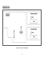
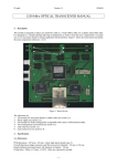
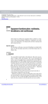
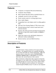
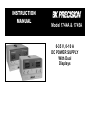
INSTRUCTION
MANUAL
Model 1744A & 1745A
0-35 V, 0-10 A
DC POWER SUPPLY
With Dual
Displays
TEST INSTRUMENT SAFETY
WARNING
Normal use of test equipment exposes you to a certain amount of danger from electrical shock because testing must sometimes be
performed where exposed high voltage is present. An electrical shock causing 10 milliamps of current to pass through the heart will stop
most human heartbeats. Voltage as low as 35 volts dc or ac rms should be considered dangerous and hazardous since it can produce a
lethal current under certain conditions. Higher voltages are even more dangerous. Your normal work habits should include all accepted
practices to prevent contact with exposed high voltage, and to steer current away from your heart in case of accidental contact with a
high voltage. Observe the following safety precautions:
1. There is little danger of electrical shock from the dc output of this power supply. However, there are several other possible test
conditions using this power supply that can create a high voltage shock hazard:
a. If the equipment under test is the “hot chassis” type, a serious shock hazard exists unless the equipment is unplugged (just turning
off the equipment does not remove the hazard), or an isolation transformer is used.
b. If the equipment under test is “powered up” (and that equipment uses high voltage in any of its circuits), the power supply outputs
may be floated to the potential at the point of connection. Remember that high voltage may appear at unexpected points in
defective equipment. Do not float the power supply output to more than 100 volts peak with respect to chassis or earth ground.
c. If the equipment under test is “off” (and that equipment uses high voltage in any of its circuits under normal operation), discharge
high- voltage capacitors before making connections or tests. Some circuits retain high voltage long after the equipment is turned
off.
2. Use only a polarized 3-wire ac outlet. This assures that the power supply chassis, case, and ground terminal are connected to a good
earth ground and reduces danger from electrical shock.
3. Don’t expose high voltage needlessly. Remove housings and covers only when necessary. Turn off equipment while making test
connections in high-voltage circuits. Discharge high-voltage capacitors after removing power.
(continued on inside back cover)
2
TABLE OF CONTENTS
Page
Page
TEST INSTRUMENT SAFETY --------------inside front cover
APPLICATIONS------------------------------------------------ 20
General -------------------------------------------------------- 20
Electronics Servicing ---------------------------------------- 20
Electronics Manufacturing ---------------------------------- 20
Electronics Design Lab -------------------------------------- 20
Electronics Education---------------------------------------- 21
Battery Charging --------------------------------------------- 21
INTRODUCTION ------------------------------------------------- 4
FEATURES -------------------------------------------------------- 5
SPECIFICATIONS ------------------------------------------------ 6
CONTROLS AND INDICATORS------------------------------- 8
MAINTENANCE ----------------------------------------------- 22
Fuse Replacement -------------------------------------------- 22
Line Voltage Conversion------------------------------------ 22
Adjustments--------------------------------------------------- 22
1743B Calibration -------------------------------------------- 23
Instrument Repair Service----------------------------------- 23
OPERATING INSTRUCTIONS --------------------------------10
Safety Precautions --------------------------------------------- 10
Equipment Precautions ---------------------------------------- 10
Hook-Up -------------------------------------------------------- 10
Typical Constant Voltage Operation------------------------- 13
Setting Current Limit ------------------------------------------14
Typical Constant Current Operation ------------------------- 15
Constant Voltage/Constant Current Characteristic --------- 16
Connecting Two Power Supplies in Series ------------------ 16
Connecting Two Power Supplies in Parallel ---------------- 19
WARRANTY SERVICE INSTRUCTIONS ----------------- 25
LIMITED TWO- YEAR WARRANTY ----------------------- 26
SPANISH MANUAL ------------------------------------------- 28
3
INTRODUCTION
The B+K Precision Models 1744A &1745A DC Power
Supplies are high quality, general purpose dc power sources.
They provide 0-35 volts dc output, adjustable with both coarse
and fine voltage controls for precise settability. The current
output is 0-10 amps, adjustable with both coarse and fine current
controls (model 1745A). Two large LED meters continuously
monitor the output voltage and current (model 1745A). The
VOLTAGE meter is green, while the CURRENT meter is red
(model 1745A).
Current limits are adjustable from 5% to 100% of maximum.
In constant current applications, the maximum voltage may
be preset. When load variations cause current to drop below
the regulated value, the unit reverts to regulated voltage
operation at the preset value.
Reverse polarity protection prevents accidental damage to
the power supply from improper connection to an external
voltage, and current limiting protects the equipment being
powered, as well as the power supply.
These models exhibit excellent regulation and low ripple
characteristics. The circuit design incorporates a pre-regulator,
which greatly reduces internal power dissipation at low output
voltages. The styling is both attractive and functional.
The output is isolated from chassis and earth ground,
which permits full flexibility of connections. When needed,
the (+) or (- ) polarity may be strapped to ground, or either
polarity may be floated to an external voltage. Two supplies
may be connected in series as a 0-to- 70 volt power source, or
two supplies may be connected in parallel, with suitable
balancing resistors, for up to twice the output current.
These instruments may be used in constant voltage or constant
current applications. The crossover from constant voltage to
constant current modes is smooth and automatic. LED’s indicate
the “CV” (constant voltage) or “CC” (constant current) mode of
operation. In constant voltage applications, a current limit may
be preset. When load variations cause the current to reach the
preset limit, the unit then regulates output current rather than
output voltage.
These power supplies are well suited for a wide variety of
electrical and electronics applications, including service
shops, engineering labs, production testing, school
laboratories, and home use by hobbyists.
4
FEATURES
LED INDICATORS
0-35 VOLTS
Act as pilot light and identify mode of operation and metering.
Continuously variable over 0-to-35 volts with coarse & fine controls.
PRE-REGULATOR
0-10 AMPS
Limits internal dissipation for higher reliability.
0-to-10 amps current rated for continuous duty at full output current.
Coarse and fine current adjust controls.
ISOLATED OUTPUT
LABORATORY QUALITY
Either polarity may be floated or grounded.
Excellent regulation, low ripple.
OVERLOAD PROTECTION
CONSTANT VOLTAGE OR CONSTANT CURRENT
Fully adjustable current limiting (from 5% to 100% of
maximum output current) protects circuit under test and the
power supply.
Provides regulated dc voltage output or regulated dc current output.
Crossover is smooth and automatic.
REVERSE POLARITY PROTECTION
LED DISPLAYS (model 1745A)
Prevents damage to power supply from external voltage of
reverse polarity.
Two large, easy-to-read LED digit displays monitors output voltage
and output current, and p rovides good visibility in bright or low
light.
STYLING
Two Current Ranges (model 1744A)
Modern functional styling.
controls.
High-Low switch selects full output (0-10A), or on quarter
output (0-2.2A). Low range improves current settability and
meter resolution.
5
Logical, convenient layout of
SPECIFICATIONS
OUTPUT VOLTAGE:
adjustment.
0 to 3 5 VDC, coarse and fine
OUTPUT CURRENT:
adjustment.
0
to
10 A,
coarse and
fine
CONSTANT VOLTAGE OPERATION
Voltage Regulation
Line (108 -132 V):
Load (no load to full load):
≤0.2% +2 mV
≤0.04% + ≤0.04% + 2 mV
Recovery Time:
≤100 μs typical.
Ripple Voltage
RMS:
≤1 mV.
Temperature Coefficient
(0° to +40 °C):
≤300 PPM/°C
4 digit Green LED Display
0 to 99.99 V.
(0.5% + 9 digits)
Ammeter
Hi Range:
Accuracy:
4 digit Red LED Display
0 to 9.999 A.
(0.5% + 9 digits).
Model 1744A
Voltmeter Range:
Accuracy:
0 to 40 V
+2.5%
Ammeter Hi Range:
Lo Range:
Accuracy:
0 to 11 A
0 to 2.2 A.
+2.5%
POWER REQUIREMENTS:
Domestic: 120 VAC ±10%, 60 Hz
International: 120/220/230/240 VAC - 10%, 50/60 Hz
CONSTANT CURRENT OPERATION
Adjustable Current Limits:
Current Regulation
Line (108 -132 V):
Load
Current Ripple:
METERING
Model 1745A
Voltmeter
Range:
Accuracy:
5% to 100%
POWER CONSUMPTION:
Approximately 420 W or less at
full load.
≤0.4% + 5 mA
≤0.4% + 5 mA
≤3 mA typical.
PROTECTION:
Reverse polarity protection,
Current limiting.
6
SPECIFICATIONS
WEIGHT:
TEMPERATURE RANGE
Operation:
Storage:
0° to +40° C, ≤75% R.H.
-15° to +70° C,≤85% R.H.
DIMENSIONS (HxWxD):
5.7” x 10.5” x 15” (145 x 267 x 38 mm)
27 lb. (12.25 kg)
ACCESSORIES SUPPLIED: Instruction Manual,
Spare Fuse
NOTE: Specifications and information are subject to change without notice. Please visit www.bkprecision.com for the most current
product information.
Note 1:
Important: Even with noticeable Thermal Drift, this high resolution power supply will be considerably more accurate than any standard
three digit display bench power supply.
Thermal Drift: Since this power supply has greater resolution than standard bench power supplies they are more susceptible to Thermal
Drift. Thermal Drift occurs on almost every type of power supply but is more apparent on high resolution types. Thermal Drift results in the
metering of the power supply to either slowly increase or decrease with the change in the power supply’s internal temperature. As the power
supply outputs more power its internal temperature will increase causing the metering (primarily the current) to slowly increase. As the
power demand is deceased the power supply will cool causing the metering (primarily the current) to slowly decrease. If the power supply
remains with a constant output of power for more than fifteen minutes the power supply metering will remain constant and should not
continue to drift.
7
CONTROLS AND INDICATORS
INDICATORS
CURRENT CONTROL
Either the “CC” or “CV” and the LED indicators will be lit
whenever the unit is operating, thus serving as a pilot light. The unit
automatically changes from CV to CC operation when the preset
current limit is reached.
1. C.C. (Constant Current) Indicator. Red LED lights in constant
current mode. Unit regulates output current at value set by CURRENT controls.
2. C.V. (Constant Voltage) Indicator. Green LED lights in constant
voltage mode. Unit regulates output voltage at value set by
VOLTAGE controls.
3. GREEN LED Display (1745A). 4 digit display continuously
monitors voltage.
4. RED LED Display (1745A). 4 digit display continuously
monitors current.
VOLTAGE CONTROLS
7.
8.
Coarse CURRENT Control. Adjusts current limit in
constant voltage mode. Adjusts constant current value
in constant current mode. Current can be read from
RED LED display.
Fine Control (1745A). Fine adjustment of current limit
or current value. Current can be read from RED LED
display.
OUTPUT TERMINALS
9. “+” Terminal (Red). Positive polarity output terminal.
10. GND Terminal. Earth and chassis ground.
11. “-” Terminal (Black). Negative polarity output
terminal.
REAR PANEL CONTROLS
5. Coarse Control. Coarse adjustment of output voltage. Read value
on GREEN LED display.
6. Fine Control. Fine adjustment of output voltage. Read value on
GREEN LED display.
8
12. Fuse
13. Power Cord
CONTROLS AND INDICATORS
REAR PANEL CONTROLS
7. Fuse.
8. Power Cord.
9. 110/220 Line Voltage Conversion Switch.
Figure 1. Front Panel Controls and Indicators.
Figure 2. Rear Panel
9
OPERATING INSTRUCTIONS
SAFETY PRECAUTIONS
Do not exceed the voltage rating of the circuit being
pow ered. Most transistors and integrated circuits will not
withstand voltage of 35 volts.
Use only a polarized 3-wire ac outlet. This assures that the power
supply chassis, case, and ground terminal are connected to a good
earth ground and reduces danger from electrical shock.
There is no need to worry about voltage spikes or overshoot
damaging the equipment under test. The voltage between the
output terminals of the power supply never exceeds the preset
value as the POWER switch is turned on or off.
There is little danger of electrical shock from the power supply
output, which produces a maximum of 35 volts dc. However, there
may be great danger of electrical shock if the power supply
output is connected to an external high voltage. Some equipment
being powered may contain high voltage and present a serious
hazard. Observe caution. If the power supply output is floated
(referenced to a voltage rather than earth ground) turn off the power
supply and the equipment under test when making connections.
Never float the power supply to a potential greater than 100 volts
peak with respect to earth ground.
HOOK-UP
1. Turn off the power supply and the equipment to be
powered during hook-up.
2. Connect the positive polarity of the device being powered
to the red (+) terminal of the power supply.
3. Connect the negative polarity of the device being powered
to the black (-) terminal of the power supply.
4. Fig. 3 illustrates the grounding possibilities.
a. If the negative polarity of the equipment or circuit
being powered is also the chassis or common, it may be
grounded to earth by strapping the black (-) terminal to
the green ( ) terminal as shown in Fig. 3A.
b. Similarly, the positive polarity can be grounded by
strapping the red (+) terminal to the green ( ) terminal
as shown in Fig. 3B.
EQUIPMENT PRECAUTIONS
Avoid using the power supply in ambient temperatures above
+40° C. Always allow sufficient air space around the heat sink at
the rear of the power supply for effective radiation to prevent
internal heat build-up.
Although the power supply is protected against reverse polarity
damage, the circuit being powered may not include such protection.
Always carefully observe polarity; incorrect polarity may damage
the equipment under test.
10
OPERATING INSTRUCTIONS
Figure 3 (A and B). Grounding Possibilities.
11
OPERATING INSTRUCTIONS
Figure 3 (C and D). Grounding Possibilities.
12
OPERATING INSTRUCTIONS
c. If an earth ground reference is not required, the
configuration of Fig. 3Bmay be used. The scheme in Fig. 3C
should also be used where it is not known whether the
chassis is common with either the positive or negative
polarity.
d. If the chassis or common of the equipment being powered is
separate from both the positive and negative polarity power
[email protected]
inputs, use the connection shown in Fig. 3D.
5. Observe proper polarity. If the circuit being powered is not
equipped with reverse polarity protection, damage to the circuit can
result from reverse polarity. Use color coded hook-up leads, for
convenience in identifying polarity, red for (+) and black for (-).
6.Make sure that the hook-up leads offer sufficient current
capability and low resistance between the power supply and the
circuits being powered.
TYPICAL CONSTANT VOLTAGE OPERATION
1. Before connecting the device to be powered to the power
supply, determine the maximum safe load current for the device
to be powered and set the current limit value (see “Setting
Current Limit” procedure in this section).
2. Set Fine VOLTAGE control to center and Coarse
VOLTAGE control to minimum (fully counterclockwise).
3.Turn off power supply and connect it to the device to be
powered (see “Hook-Up” procedure in this section).
8. Turn on POWER switch. The CV indicator should light.
13
Figure 4. Typical Constant Voltage Operation.
OPERATING INSTRUCTIONS
5. . Increase the VOLTAGE setting until the Voltage LED
display reads the desired value. The FINE control permits
easier setting to a specific value.
6. Note the load current on the Current LED display.
7. If the load current exceeds the preset current limit, the CV
indicator will go off and the CC indicator will light. In this
case, the power supply automatically switches to the
constant current mode, and further rotation of the
VOLTAGE control will not increase the output voltage.
SETTING CURRENT LIMIT
1. Determine the maximum safe current for the device to be
powered.
2. Temporarily short the (+) and (- ) terminals of the power
supply together with a test lead.
3. Rotate the Coarse VOLTAGE control away from zero
sufficiently for the CC indicator to light.
4. Adjust the Coarse and Fine CURRENT control for the
desired current limit. Read the current value on the Current
LED display.
5. The current limit (overload protection) has now been preset.
Do not change the CURRENT controls settings after this
step.
6. Remove the short between the (+) and (-) terminals and hook
up for constant voltage operation.
Figure 5. Setting Current Limit.
14
OPERATING INSTRUCTIONS
TYPICAL CONSTANT CURRENT OPERATION
1. Before connecting the device to be powered to the power supply,
determine the maximum safe voltage to be applied, and set the
VOLTAGE controls to obtain that voltage reading on the Voltage
LED display.
2. Determine the desired constant current value.
3. Set the Coarse and Fine CURRENT control to minimum (fully
counterclockwise).
4. Turn off the power supply and connect it to the device to be
powered.
5. Turn on the power supply. The CC indicator should light.
6. Increase the Coarse and Fine CURRENT control setting until the
desired constant current value is read on the display, or set the
current limit in advance (before connecting the load) as prescribed
in the earlier “Setting Current Limit” procedure.
7. If the load current drops below the constant current value, the CC
indicator will go off and the CV indicator will light. In this case,
the power supply automatically switches to the constant voltage
mode, and further rotation of the CURRENT controls will not
increase the output current.
Figure 6. Typical Constant Current
Operation.
15
OPERATING INSTRUCTIONS
CONSTANT VOLTAGE/CONSTANT CURRENT
CHARACTERISTIC
The working characteristic of this power supply is called a constant
voltage/constant current automatic crossover type. This permits
continuous transition from constant current to constant voltage modes in
response to the load change. The intersection of constant voltage and
constant current modes is called the crossover point. Fig. 7 shows the
relationship between this crossover point and the load.
For example, if the load is such that the power supply is operating in
the constant voltage mode, a regulated output voltage is provided. The
output voltage remains constant as the load increases, up until the point
where the preset current limit is reached. At that point, the output current
becomes constant and the output voltage drops in proportion to further
increases in load. The crossover point is indicated by the front panel LED
indicators. The crossover point is reached when the CV indicator goes off
and the CC indicator comes on.
Similarly, crossover from the constant current to the constant voltage
mode automatically occurs from a decrease in load. A good example of
this would be seen when charging a 12-volt battery. Initially, the open
circuit voltage of the power supply may be preset for 13.8 volts. A low
battery will place a heavy load on the supply and it will operate in the
constant current mode, which may be adjusted for a 1 amp charging rate.
As the battery becomes charged, and its voltage approaches 13.8 volts, its
load decreases to the point where it no longer demands the full 1 amp
charging rate. This is the crossover point where the power supply goes
into the constant voltage mode.
16
Figure 7. Constant Voltage/Constant Current Characteristic.
CONNECTING TWO POWER SUPPLIES IN SERIES
Two Model 1743B power supplies may be connected in
series to provide a variable 070 volt output. In this
configuration, two 1743B’s provide up to 6 amps. See Fig. 8
for the connection scheme.
When connected in series, the VOLTAGE controls of each
power supply exercise control over a 0-35 volt range. Add the
two LED readings together to determine the total output
voltage. Or connect an external voltmeter across the load.
Load current may be monitored from either supply; the
readings will be identical since they are connected in series.
Also, since the supplies are connected in series, it is only
necessary to set the current limit on one of the supplies; the
other may be set for maximum.
OPERATING INSTRUCTIONS
Figure 8. Connecting Two Power Supplies in Series.
17
OPERATING INSTRUCTIONS
Figure 9. Connecting Two Power Supplies in Parallel.
18
OPERATING INSTRUCTIONS
CONNECTING TWO POWER SUPPLIES IN PARALLEL
If the current equalizing resistors are not well matched, it is
preferable that the voltages be slightly unbalanced to achieve
current balance. Be sure that the supplies are adequately
balanced so that both remain in the CV mode.
Two power supplies may be connected in parallel to double the
maximum load current. In this configuration the two supplies will
provide two 0-35 volt output at up to 20 amps (heavier gauge
hook-up leads are advisable). Current equalizing resistors must be
used as shown in Fig. 9. However, the protective current limiting
feature will prevent damage if current is temporarily unbalanced
during set-up.
When connected in parallel and operating in the constant
current mode, the VOLTAGE controls of both supplies should
be preset to the same value. Then when the load is connected, the
CURRENT controls of the two supplies should be adjusted for
approximately equal current from each unit. Be sure that both
supplies remain in the CC mode.
When connected in parallel and operating in the constant
voltage mode, determine the total load current limit and preset the
current limiting for each power supply to half the total load
current value. Then when the load is connected, set the
VOLTAGE controls on the two power supplies for equal voltage
readings. This should also provide approximately equal current
from each supply. Add the two current readings together for total
load current, or connect an external ammeter in series with the
load.
19
APPLICATIONS
GENERAL
These model power supplies have a very wide variety of
applications in electrical and electronics servicing, engineering
laboratories, manufacturing and testing facilities, schools, and
home hobbies. The power supply output is fully adjustable from 0
to 35 volts and 0 to 10 amps. This flexibility makes them suitable
for most applications requiring a dc power source.
The equipment being tested may contain its own power
supply and operate from ac power. A dc voltage may already
be present in the circuit. One polarity of the power supply
output is floated to an appropriate point in the circuit, such as
the emitter of a transistor. The other polarity of the power
supply output is then applied to another point in the circuit,
such as the base of that transistor. Varying the power supply
voltage then varies the dc bias on the stage, and the effects
may be noted. A series limiting resistor is often used to
protect the circuits from overdissipation.
ELECTRONICS SERVICING
Most electronics troubleshooting and repair is performed on a
test bench. This power supply can provide the dc power source to
operate a module or circuit board on the test bench when it is
removed from its parent equipment. It can be used to power
portable, battery-operated equipment and check the effect of low
battery voltage. It can power vehicular equipment such as tape
players, auto sound systems, CB radios, etc. on the test bench.
Most automobiles and other vehicles use 12-volt electrical
systems. Although the electrical system is normally referred to as
a 12-volt system, actual battery voltage when fully charged is
approximately 14 volts. The power supply may be set to 14 volts
for servicing equipment from vehicles with 12-volt electrical
systems. Some trucks use a 24-volt electrical system; bench
testing of equipment from these systems should be performed at
28 volts.
Some servicing applications require the injection of a variable
dc voltage for certain tests, such as checking the effect of AGC
bias in a television receiver. This requires an isolated dc power
supply, such as the Model 1743B.
ELECTRONICS MANUFACTURING
In electronics manufacturing facilities, the power supply is
often used as a dc power source while testing and adjusting
modules, subassemblies, and complete units in the production
and assembly area or in the quality control area. The
instrument can be used in incoming inspection as a dc power
source for testing purchased components and subassemblies.
This power supply is particularly well suited for
manufacturing applications because of its ease of operation
and its continuous duty rating. When load current or total
power dissipation are among the main characteristics to be
measured, the total load current and voltage are easily
displayed on the LED displays. The current limit can be set
so that all units which do not meet the load current
specification will cause the CC indicator to light, and the unit
can be rejected.
20
APPLICATIONS
ELECTRONICS DESIGN LAB
BATTERY CHARGING
The technician or engineer working in an engineering laboratory
requires a dc power supply to power breadboard and prototype
circuits. This power supply is ideal because it monitors output
current, output voltage, limits current to protect the circuit, is
adjustable over a wide range, and has excellent regulation and very
low ripple.
The power supply can be used as a battery charger to
restore the charge in rechargeable batteries such as lead-acid,
nickel-cadmium, and some alkaline types. Refer to the
battery manufacturer’s charging specifications for proper
voltage and current settings. Charging information is
sometimes printed on the batteries. Battery charging, at least
initially, requires the constant current mode of operation.
Before connecting the power supply to the battery, preset the
VOLTAGE controls to the fully charged terminal voltage
specified by the battery manufacturer. Turn off the power
supply while connecting the battery. Observe proper polarity
and connect as for constant current operation. Adjust the
CURRENT control for the maximum charging current
specified by the battery manufacturer. (If the maximum
charging current is greater than the power supply’s maximum
load current, set the CURRENT control to maximum). The
CC indicator will light and the battery will charge at the
preset current limit. As the battery approaches full charge, its
terminal voltage will approach that of the power supply
output and the charging current will taper off. The power
supply may automatically switch to CV (constant voltage)
operation. When this occurs, the power supply will continue
to provide a trickle charge.
Use of the instrument in an engineering laboratory is very
similar to that described for servicing electronics equipment and
modules, except that lower currents may be prevalent when
powering individual circuits. The current limiting feature is very
valuable in this application because it can protect unproven circuits
from damage.
ELECTRONICS EDUCATION
The student in an electronics curriculum may use the power
supply for powering equipment and circuits as previously
described for all other applications. In addition, the power supply
can be used in the classroom laboratory to conduct experiments in
f undamental electronics. In learning Ohm’s law, for example, the
relationships of resistance, current, and voltage are easily
demonstrated by the use of a power supply. Being able to observe
both the current and voltage meter simultaneously is a great aid in
such experiments.
21
MAINTENANCE
WARNING
LINE VOLTAGE CONVERSION, INTERNATIONAL
UNITS
The following instructions are for use by qualified personnel only. To
avoid electrical shock, do not perform any servicing other than
contained in the operating instructions unless you are qualified to do
so.
The primary winding of the power transformer is tapped to
permit operation from 120/220/230 or 240 VAC, 50/60 Hz
line voltage. Conversion from one line voltage to another is
done by a simple position change of the fuse receptacle
underneath the line cord.
FUSE REPLACEMENT
ADJUSTMENTS
If the fuse blows, the CV or CC indicators will not light and the
power supply will not operate. The fuse should not normally open
unless a problem has developed in the unit. Try to determine and
correct the cause of the blown fuse, then replace only with a fuse of
the correct rating as listed below. The fuse is located on the rear panel
(see Fig. 2).
OPERATION
120 V
220/230/240 V
This unit was accurately adjusted at the factory before
shipment. Readjustment is recommended only if repairs have
been made in a circuit affecting adjustment accuracy, or if
you have a reason to believe the unit is out of adjustment.
However, adjustments should be attempted only if a
multimeter with an accuracy of ±0.5% DCV or better is
available (B+K Precision Model 2703B or equivalent).
FUSE VALUE
TYPE
6A
SLOW BLOW
3A
SLOW BLOW
Table 1. Fuse Values.
22
MAINTENANCE
CALIBRATION
If readjustment is required, use the following procedure. Locations
of the adjustments are shown in Fig. 11.
1. Set the front panel controls of the Model 1743BA as follows:
Coarse and Fine VOLTAGE controls fully clockwise. Coarse
and Fine CURRENT controls fully clockwise. Power switch to
On.
2. Connect the Multimeter to measure the voltage at pin 14 of IC2
with respect to the front panel red (+) output jack. Adjust R21
for -5.00 volts on the Multimeter.
3. Connect the Multimeter to measure the voltage at pin 8 of IC2
with respect to the front panel red (+) output jack. Adjust R64
for 0 + l 0 mV on the Multimeter.
4. Connect the Multimeter to measure the DC voltage between the
black (-) and red (+) output jacks. The voltage should be 35 to
37 volts, the green CV indicator should be lit, and the red CC
indicator should be off.
5. Set the front panel Fine VOLTAGE control for a reading of
35.00 volts on the Multimeter. Adjust upper GREEN R304 for a
front panel meter reading of 35.00 volts on the GREEN
VOLTAGE meter.
23
6. Set the front panel Coarse VOLTAGE control for a
reading of 04.00 to 06.00 volts on the GREEN
VOLTAGE meter.
7. Connect the Multimeter to read the DC current
between the black (-) and red (+) output jacks, using
the 10 amp range. The red CC indicator should light
and the green CV indicator should go off.
8. Set the front panel Fine CURRENT control for a
reading of 6.000 amps on the Multimeter. Adjust
lower RED R304 for a front panel meter reading of
6.000 amps on the RED CURRENT meter.
INSTRUMENT REPAIR SERVICE
Because of the specialized skills and test equipment
required for instrument repair and calibration, many
customers prefer to rely upon B+K Precision for this
service. We maintain a network of B+K Precision
authorized service agencies for this purpose. To use this
service, even if the instrument is no longer under
warranty, follow the instructions given in the
WARRANTY SERVICE INSTRUCTIONS section of
this manual. There is a nominal charge for instruments out
of warranty.
MAINTENANCE
Figure 11. Location of Adjustments.
24
Service Information
Warranty Service: Please return the product in the original packaging with proof of purchase to the address
below. Clearly state in writing the performance problem and return any leads, probes, connectors and accessories
that you are using with the device.
Non-Warranty Service: Return the product in the original packaging to the address below. Clearly state in writing
the performance problem and return any leads, probes, connectors and accessories that you are using with the
device. Customers not on open account must include payment in the form of a money order or credit card. For the
most current repair charges please visit www.bkprecision.com and click on “service/repair”.
Return all merchandise to B&K Precision Corp. with pre-paid shipping. The flat-rate repair charge for NonWarranty Service does not include return shipping. Return shipping to locations in North American is included for
Warranty Service. For overnight shipments and non-North American shipping fees please contact B&K Precision
Corp.
B&K Precision Corp.
22820 Savi Ranch Parkway
Yorba Linda, CA 92887
www.bkprecision.com
714-921-9095
Include with the returned instrument your complete return shipping address, contact name, phone
number and description of problem.
25
Limited Two-Year Warranty
B&K Precision Corp. warrants to the original purchaser that its products and the component parts thereof, will be
free from defects in workmanship and materials for a period of two years from date of purchase.
B&K Precision Corp. will, without charge, repair or replace, at its option, defective product or component parts.
Returned product must be accompanied by proof of the purchase date in the form of a sales receipt.
To obtain warranty coverage in the U.S.A., this product must be registered by completing a warranty registration
form online at www.bkprecision.com within fifteen (15) days of purchase.
Exclusions: This warranty does not apply in the event of misuse or abuse of the product or as a result of
unauthorized alterations or repairs. The warranty is void if the serial number is altered, defaced or
removed.
B&K Precision Corp. shall not be liable for any consequential damages, including without limitation damages
resulting from loss of use. Some states do not allow limitations of incidental or consequential damages. So the
above limitation or exclusion may not apply to you.
This warranty gives you specific rights and you may have other rights, which vary from state-to-state.
B&K Precision Corp.
22820 Savi Ranch Parkway
Yorba Linda, CA 92887
www.bkprecision.com
714-921-9095
Model Number: _______________
Date Purchased: __________________
26
TEST INSTRUMENT SAFETY
(continued from inside front cover)
4. If possible, familiarize yourself with the equipment being tested and the location of its high voltage points. However, remember
that high voltage may appear at unexpected points in defective equipment.
5. Use an insulated floor material or a large, insulated floor mat to stand on, and an insulated work surface on which to place
equipment; and make certain such surfaces are not damp or wet.
6. When testing ac powered equipment, the ac line voltage is usually present on some power input circuits such as the on- off
switch, fuses, power transformer, etc. “any time” the equipment is connected to an ac outlet.
7. B+K Precision products are not authorized for use in any application involving direct contact between our product and the
human body, or for use as a critical component in a life support device or system. Here, “direct contact” refers to any
connection from or to our equipment via any cabling or switching means. A “critical component” is any component of a life
support device or system whose failure to perform can be reasonably expected to cause failure of that device or system, or to
affect its safety or effectiveness.
8. Never work alone. Someone should be nearby to render aid if necessary. Training in CPR (cardio-pulmonary resuscitation) first
aid is highly recommended.
27
22820 Savi Ranch Parkway
Yorba Linda, CA 92887
www.bkprecision.com
© 2008 B&K Precision Corp.
V090308
Printed in Taiwan