1
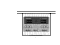
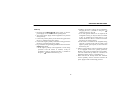
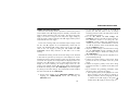
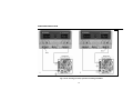
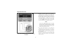
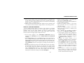
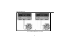
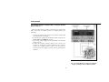
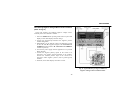
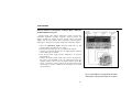
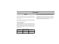
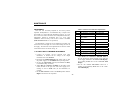
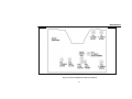
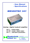
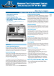
INSTRUCTION
MANUAL
Manual de Instruccíon
MODELS: 1760A & 1761
Para los modelos 1760A y 1761
Triple Output
DC POWER SUPPLY
With Dual 4-Digit LED Displays
Fuentes de Poder de Triple Salida
DC
Con Pantalla tipo LED Dual de 4
Dígitos
TEST INSTRUMENT SAFETY
WARNING
Normal use of test equipment exposes you to a certain amount of danger from electrical shock because testing must sometimes be
performed where exposed high voltage is present. An electrical shock causing 10 milliamps of current to pass through the heart will
stop most human heartbeats. Voltage as low as 35 volts dc or ac rms should be considered dangerous and hazardous since it can
produce a lethal current under certain conditions. Higher voltages are even more dangerous. Your normal work habits should
include all accepted practices to prevent contact with exposed high voltage, and to steer current away from your heart in case of
accidental contact with a high voltage. Observe the following safety precautions:
1. There is little danger of electrical shock from the dc output of this power supply. However, there are several other possible test
conditions using this power supply that can create a high voltage shock hazard:
a. If the equipment under test is the “hot chassis” type, a serious shock hazard exists unless the equipment is unplugged (just
turning off the equipment does not remove the hazard), or an isolation transformer is used.
b. If the equipment under test is “powered up” (and that equipment uses high voltage in any of its circuits), the power supply
outputs may be floated to the potential at the point of connection. Remember that high voltage may appear at unexpected
points in defective equipment. Do not float the power supply output to more than 100 volts peak with respect to chassis or
earth ground.
c. If the equipment under test is “off” (and that equipment uses high voltage in any of its circuits under normal operation),
discharge high-voltage capacitors before making connections or tests. Some circuits retain high voltage long after the
equipment is turned off.
2. Use only a polarized 3-wire ac outlet. This assures that the power supply chassis, case, and ground terminal are connected to a
good earth ground and reduces danger from electrical shock.
3. Don’t expose high voltage needlessly. Remove housings and covers only when necessary. Turn off equipment while making
test connections in high-voltage circuits. Discharge high-voltage capacitors after removing power.
(continued on inside back cover)
2
Instruction Manual
For Models
1760A and 1761
Triple Output DC Power Supplies
With Dual 4-Digit LED Displays
22820 Savi Ranch Parkway
Yorba Linda, CA 92887
www.bkprecision.com
3
TABLE OF CONTENTS
page
TEST INSTRUMENT SAFETY------------- inside front cover
Page
APPLICATION ----------------------------------------------------- 33
General --------------------------------------------------------------- 33
Electronics Servicing ----------------------------------------------- 33
Electronics Manufacturing----------------------------------------- 33
Electronics Design Lab -------------------------------------------- 34
Electronics Education ---------------------------------------------- 34
Battery Charging ---------------------------------------------------- 34
Split Supply---------------------------------------------------------- 34
INTRODUCTION ------------------------------------------------- 5
FEATURES -------------------------------------------------------- 7
SPECIFICATIONS ------------------------------------------------ 8
CONTROLS AND INDICATORS ---------------------------General Controls and Indicators ------------------------------4-6.5 V Supply Controls and Indicators ---------------------“A” Supply Controls and Indicators -------------------------“B” Supply Controls and Indicators--------------------------Rear Panel Controls ---------------------------------------------
10
10
10
12
12
13
OPERATING INSTRUCTIONS------------------------------Safety Precautions ----------------------------------------------Equipment Precautions-----------------------------------------Independent Use of “A” Or “B” Supply ---------------------Hook-up----------------------------------------------------------Typical Constant Voltage Operation -------------------------Setting Current Limit ------------------------------------------Typical Constant Current Operation -------------------------Constant Voltage/Current Characteristic --------------------Series Tracking Operation -------------------------------------Parallel Tracking Operation -----------------------------------4-6.5 V Power Supply Operation ------------------------------
14
14
14
14
15
18
19
20
21
22
26
29
MAINTENANCE --------------------------------------------------- 41
Fuse Replacement--------------------------------------------------- 41
Line Voltage Conversion ------------------------------------------ 41
Adjustments --------------------------------------------------------- 42
“A” Supply and “A” Metering Adjustments -------------------- 42
4-6.5 V Supply and 4-6.5 V Metering Adjustments ------------ 44
“B” Supply and Metering Adjustments -------------------------- 44
“B” Series Tracking Adjustment---------------------------------- 45
Instrument Repair Service ----------------------------------------- 45
WARRANTY SERVICE INSTRUCTIONS--------------------- 46
LIMITED TWO-YEAR WARRANTY -------------------------- 47
SPANISH MANUAL----------------------------------------------- 50
4
INTRODUCTION
These B+K Precision Triple Output DC Power Supplies are high
quality, general purpose dc power sources. They provide two “main”
supplies with a 0-30V (0-35V model 1761) volt dc output and a “third”
output with a 4-6.5A (2-6.5A model 1761) volt dc output. The “main”
V supplies are adjustable with both coarse and fine voltage controls for
precise settability and are capable of current output of 0-2 (0-3 model
1761) amps. The “third” supply has a current output of 0-5 amps,
allowing it to handle extensive digital logic circuitry. Two large panel-mounted LED meter displays can monitor either the output current or
output voltage of each supply.
The two “main” volt supplies can be operated independently or in
one of two tracking modes. In the series tracking mode, the “B” Supply
tracks from 5% to 100% of the voltage of the “A” Supply. Maximum
current setting of the two supplies can still be set independently when
in the series tracking operating mode. In the series tracking mode the
“A” and “B” supplies are connected in series, allowing a single output
of 0-60 (0-70 model 1761) V at up to 2 (3 model 1761) amps. In the
parallel tracking mode, the two supplies are connected together in
parallel, allowing a single 0-30 (0-35 model 1761) V output at up to 4
(6 model 1761) amps.
Both “main” volt supplies may be used in constant voltage or
constant current applications. The crossover from constant voltage to
constant current modes is smooth and automatic. LED’s indicate the
“CV” (constant voltage) or “CC” (constant current) mode of operation.
In constant voltage applications, a current limit may be preset. When
load variations cause the current to reach the preset limit, the unit then
regulates output current rather than output voltage. Current limits are
adjustable from 5% to 100% of maximum.
5
In constant current applications, the maximum voltage may
be preset. When load variations cause current to drop below
the regulated value, the unit reverts to regulated voltage
operation at the preset value.
The “third” V supply is ideal for powering digital logic
circuitry. The 0-5 amp capacity allows the supply to be used
for large circuits. Built-in overload protection automatically
limits the current output to a maximum of 5 amps. An
indicator lights when the supply is overloaded.
These models exhibit excellent regulation and low ripple
characteristics. The circuit design incorporates a pre-regulator,
which greatly reduces internal power dissipation at low output
voltages.
Reverse polarity protection prevents accidental damage to
the power supply from improper connection to an external
voltage, and current limiting protects the equipment being
powered, as well as the power supply.
The output is isolated from chassis and earth ground, which
permits full flexibility of connections. When needed, the (+)
or (-) polarity may be strapped to ground, or either polarity
may be floated to an external voltage. Additionally, the two
“main” volt supplies can be used as a “split supply” with two
positive voltages and a common negative, two negative
voltages and a common positive, or one positive, one
negative, and a common. All of these configurations can be
used with either matching (tracking) or differing
(independent) voltages.
The features and versatility of the unit, especially the triple output
and tracking features, make it an ideal general purpose power
supply for engineering lab applications. It can serve as a single or
multi-voltage power source, including the bias supply, for
breadboard and prototype circuits and equipment. It can provide
single or simultaneously varying voltages for circuit evaluation. It
can provide tracking (+) and (-) voltages for evaluating differential
amplifiers. It may be used as a battery eliminator, or to power
individual circuit boards or cards while removed from the system.
Its output can be evaluated while powering a breadboard or
prototype circuit to determine the circuit’s power supply
requirements. Its laboratory quality specifications will meet most
engineering laboratory requirements.
The same features that make the Model 1760 a good
choice for an engineering lab also make it a good choice for
most other solid state electronic applications. These
applications include service shops; industrial production
testing of components, assemblies, and complete equipment;
for school laboratories, and home use by electronic
hobbyists.
6
FEATURES
TRIPLE OUTPUT
Operates as three separate power supplies. Each has floating
output and is completely isolated from the other two.
CONSTANT VOLTAGE OR CONSTANT CURRENT
The “A” and “B” supplies provide regulated dc voltage
output or regulated dc current output. Crossover is smooth and
automatic.
ONE 4 TO 6.5 V (2 to 6.5V model 1761) SUPPLY
Durable 0-to-5 amp supply is ideal for use with most digital
logic circuitry. Adequate current capacity for extensive circuitry.
LED DISPLAY
Two large, easy-to-read LED 4-digit displays monitor
output voltage or output current of all three supplies. Use of
two meters allows simultaneous current and voltage metering
when using “A” and “B” supplies in tracking operation. Good
visibility in bright or low light.
TWO 0-30 VOLT (0-35V model 1761) SUPPLIES
“A” and “B” supply are continuously variable over their
respective voltage ranges with coarse and fine controls. Each
supply has a 2 amp (3 amp model 1761) current capacity.
LABORATORY QUALITY
Excellent regulation, low ripple.
UNIQUE TRACKING FEATURE
The two 0-to-30V (35V model 1761) supplies can be operated so
that the “B” supply tracks the “A” supply. Outputs can be strapped
for two positive voltages with a common negative, two negative
voltages with a common positive, or one positive and one negative
with a neutral common.
PRE-REGULATOR
Limits internal dissipation for higher reliability and
efficiency.
ISOLATED OUTPUT
Either polarity may be floated or grounded.
SINGLE 0-60V (0-70V model 1761) SUPPLY
Series tracking feature allows use of “A” and “B” supplies as
one 0-to-60V, 2 amp (0-70V, 3 amp model 1761) supply.
OVERLOAD PROTECTION
Fully adjustable current limiting (from 5% to 100% of
maximum output current) for “A” and “B” supplies protects
circuit under test and the power supply.
SINGLE 0-30V, 4A (0-35V, 5A model 1761) SUPPLY
Parallel tracking feature allows use of “A” and “B” supply as a
0-to-30 (0-35V model 1761) V supply with a 4 amp (6 amp model
1761) current capacity (through “A” output terminals).
7
REVERSE POLARITY PROTECTION
Prevents damage to power supply from external voltage of
reverse polarity.
SPECIFICATIONS
Tracking Series, “B” tracks “A”:
5% to 100%.
Panel Meter Accuracy (Volts):
±0.5% + 9 digits.*
Panel Meter Accuracy (Current):
±0.5% + 9 digits.*
(* see note 1)
“A” AND “B” SUPPLIES
Output Voltage Range:
0V to 30V (0V to 35V model 1761)
Output Current Limit Range:
0.1A (5%) to 2A (3A model 1761) (100%).
Load Regulation (Constant Voltage):
≤0.01% + 3 mV.
Line Regulation 108 - 132 V (Constant Voltage):
≤0.01% + 3 mV.
Ripple (Constant Voltage):
≤1 mV RMS.
Recovery Time (Constant Voltage):
≤100 ~S.
Temp. Coefficient (Constant Voltage):
<300 ppm/°C.
Load Regulation (Constant Current):
≤0.2% + 3mA.
Line Regulation 108 - 132 V (Constant Current):
≤0.2% + 3mA.
Ripple Current (at 108 V for Constant Current):
≤3mA RMS.
Tracking (Series) Accuracy:
±0.2% + 10mV.
“Third” SUPPLY
Output Voltage Range:
4V to 6.5V (2V to 6.5V model 1761)
Load Regulation (Constant Voltage):
≤10mV (0 to 5A load).
Line Regulation 108 - 132V (Constant Voltage):
≤l 0mV.
Ripple and Noise:
≤2mV RMS.
Over Voltage Protection Threshold:
6.8V to 7.3V.
Panel Meter Accuracy:
Same as “A” Supply Meter.
8
SPECIFICATIONS
Dimensions (H x W x D):
5.7" x 10.5" x 15" (145 mm x 267 mm x 381 mm).
Weight:
10 kg (21 lbs).
Accessories Supplied:
Two earth ground bus straps.
GENERAL
Power Requirements:
Domestic: 120 VAC + 10%, 60 Hz.
International: 120/220/230/240 VAC -* 10%, 50/60 Hz.
Power Consumption (Fully Loaded):
Approximately 350 W.
Protection:
Reverse polarity protection and current limiting.
NOTE: Specifications and information are subject to change without notice. Please visit www.bkprecision.com for the most current product
information.
Note 1:
Important: Even with noticeable Thermal Drift, this high resolution power supply will be considerably more accurate than any standard three
digit display bench power supply.
Thermal Drift: Since this power supply has greater resolution than standard bench power supplies they are more susceptible to Thermal
Drift. Thermal Drift occurs on almost every type of power supply but is more apparent on high resolution types. Thermal Drift results in the
metering of the power supply to either slowly increase or decrease with the change in the power supply’s internal temperature. As the power
supply outputs more power its internal temperature will increase causing the metering (primarily the current) to slowly increase. As the power
demand is deceased the power supply will cool causing the metering (primarily the current) to slowly decrease. If the power supply remains
with a constant output of power for more than fifteen minutes the power supply metering will remain constant and should not continue to
drift.
9
CONTROLS AND INDICATORS
GENERAL CONTROLS AND INDICATORS
switch is in the 0-30V position (out), the LED display
monitors the “A” (0-30 V) supply. When this switch is in the
4-6.5V position (in), the LED display monitors the 4-6.5V
supply.
4. Right V/A Switch. Selects current or voltage metering mode
for the “A” 0-30 V supply or the 4-6.5 V supply (depending
on setting of 0-30 V/4-6.5 V switch). When in the A (amps)
position (in), current is read from the “A”/4-6.5 V LED
Display. When in the V (volts) position (out), voltage is read
from the “A”/ 4-6.5 V LED Display.
5. “A”/4-6.5 V LED Display. Digital display indicates voltage
or current at the 0-30 V “A” supply or the 4-6.5 V supply
(depending on the setting of the Right V/A and 0-30 V/4-6.5
V switches).
1. POWER Switch. Turns power on and off.
2. TRACKING Mode Switches. Two pushbutton switches that
select INDEPendent mode, SERies tracking mode, or PARallel
tracking mode as follows:
a. When INDEP/TRACK switch is disengaged (out), the unit is
in the INDEPendent mode and the “A” and “B” power
supplies are completely independent from one another.
b. When the INDEP/TRACK switch is engaged (in) and the
SER/PAR switch is disengaged (out), the unit is in the
TRACKing SERies mode. In this mode, maximum voltage of
both supplies is set using the “A” VOLTAGE controls
(voltage at output terminals of the “B” supply tracks the
voltage at the output terminals of the “A” supply). Also, in
this mode of operation the positive terminal (red) of the “B”
supply is internally connected to the negative terminal (black)
of the “A” supply. This allows the two supplies to be used as
one 0-to-60 volt supply.
3. When both INDEP/TRACK and SER/PAR switches are engaged
(in), the unit is in the TRACKing PARallel mode. In this mode
the “A” and “B” supplies are wired together in parallel and both
the maximum current and voltage are set using the “A” controls.
The “A” and “B” outputs can be used as two individual (but
tracking) power supplies or just the “A” output can be used as a
0-to-30 volt supply with a 4 A capability. 0-30V/4-6.5V
Switch. Controls “A”/4-6.5V LED Display. When this
4-6.5 V SUPPLY CONTROLS AND INDICATORS
6. “-” Terminal (Black). Negative polarity output terminal for
4-6.5V supply.
7. “+” Terminal (Red). Positive polarity output terminal for 46.5V supply.
8. Voltage Level Control. Adjusts output voltage for 4-6.5V
supply. Fully counterclockwise rotation adjusts output
voltage to 4V. Clockwise rotation increases voltage to a
maximum of 6.5V (full clockwise rotation).
9. 5 A OVERload Indicator. Lights when load on 4-6.5 Volt
supply becomes too large.
10
CONTROLS AND INDICATORS
Fig. 1. Front Panel Controls and Indicators.
11
CONTROLS AND INDICATORS
“A” SUPPLY CONTROLS AND INDICATORS
10. C.C. (Constant Current) Indicator. Red LED lights when “A”
supply is in the Constant Current mode. The Power Supply
regulates the output current at the value set by the “A”
CURRENT control. In the Parallel Tracking mode, when this
indicator is lit, both the “A” and “B” supplies are in the
Constant Current mode.
11. C.V. (Constant Voltage) Indicator. Green LED lights when
the “A” supply is in the Constant Voltage mode. The Power
Supply regulates the output voltage at the value set by the “A”
VOLTAGE controls. In either the Series or Parallel Tracking
mode, when this indicator is lit, both the “A” and “B” supplies
are in the Constant Voltage mode.
12. Coarse VOLTAGE Control. Coarse adjustment of the output
voltage of the “A” supply. Also functions as coarse adjustment
control for the maximum output voltage of the “B” supply when
either parallel or series tracking mode is selected. Read the
value on the “A”/4-6.5 V LED Display when the voltage (V)
and master (0-30 V) metering modes are selected.
13. Fine VOLTAGE Control. Fine adjustment of output voltage of
the “A” supply. Also functions as fine adjustment control for
the maximum output voltage of the “B” supply when either
parallel or series tracking mode is selected. Read the value on
the “A”/4-6.5 V LED Display when the voltage (V) and master
(0-30 V) metering modes are selected.
12
14. CURRENT Control. Adjusts current limit of “A” supply
in constant voltage mode. Adjusts constant current value of
“A” supply in constant current mode. Current can be read
from the “A”/4-6.5V LED Display when the current (A)
and master (0-30V) metering modes are selected.
15. “+” Terminal (Red). Positive polarity output terminal for
the “A” supply. Also serves as the positive polarity
terminal for 4 A parallel and 0-to-60 V series tracking
operation.
Terminal (Green). Earth and Chassis Ground.
16.
17. “-” Terminal (Black). Negative polarity output terminal
for the “A” supply. Also serves as the negative polarity
terminal for 4 A parallel tracking operation. In series
tracking operation, this terminal is internally tied to the (+)
positive terminal of the “B” supply.
“B” SUPPLY CONTROLS AND INDICATORS
18. C.V. (Constant Voltage) Indicator. Green LED lights
when the “B” supply is in the Constant Voltage mode. The
Power Supply regulates the output voltage at the value set
by the “B” VOLTAGE controls.
19. C.C. (Constant Current)/PARallel Indicator. Red LED
lights when “B” supply is in the Constant Current mode.
The Power Supply regulates the output current at the value
set by the “B” CURRENT control when in the series
tracking or INDEPendent modes. Also lights when the
TRACKing PARallel mode is selected.
CONTROLS AND INDICATORS
20. Coarse VOLTAGE Control. Coarse adjustment of the output
voltage of the “B” supply when the INDEPendent mode is selected.
Also sets the 5% to 100% tracking in the SERies TRACKing
mode. Disabled in the PARallel TRACKing mode. Read the value
on the “B” LED Display when the voltage (V) metering mode is
selected.
21. Fine VOLTAGE Control. Fine adjustment of output voltage of the
“B” supply when the INDEPendent mode is selected. Also sets the
5% to 100% tracking in the SERies TRACKing mode. Disabled in
the PARallel TRACKing mode. Read the value on the “B” LED
Display when the voltage (V) metering mode is selected.
22. CURRENT Control. Adjusts current limit of “B” supply in
constant voltage mode. Adjusts current value of “B” supply in
constant current mode. Current can be read from the “B” LED
Display when the current (A) metering mode is selected.
23. Left V/A Switch. Selects current or voltage metering mode for the
0-30 V “B” supply. When in the A (amps) position (in), current is
read form the “B” LED Display. When in the V (volts) position
(out), voltage is read form the “B” LED Display.
24. “B” LED Display. Digital display indicates voltage or current at
the 0-30 V “B” supply (depending on the setting of the A/V
switch).
25. “+” Terminal (Red). Positive polarity output terminal for the “B”
supply. In series tracking operation, this terminal is connected to the
negative terminal of the “A” supply.
26.
Terminal (Green). Earth and Chassis Ground.
27. “-” Terminal (Black). Negative polarity output terminal
for the “B” supply. Also serves as the negative polarity
terminal for 0-to-60 V series tracking operation.
REAR PANEL CONTROLS
28. Fuse
29. Power Cord
30. 110/220 Line Voltage Conversion Switch
Fig. 2. Rear Panel Controls.
13
OPERATING INSTRUCTIONS
SAFETY PRECAUTIONS
CAUTION
Avoid contacting the heat sink at the rear of the
power supply. When the unit is providing large
amounts of current at any or all of its outputs, the
heat sink can become very hot. Contacting the
heat sink when it is hot could result in skin burns
or damage to the equipment in contact with them.
Use only a polarized 3-wire ac outlet. This assures that the power supply chassis, case, and
ground terminal are connected to a good earth
ground and reduces danger from electrical shock.
There may be great danger of electrical shock if
the power supply output is connected to an external high voltage. Some equipment being powered
may contain high voltage and present a shock
hazard. Observe caution. If the power supply
output is floated (referenced to a voltage rather
than earth ground) turn off the power supply and
the equipment under test when making connections. Never float the power supply to a potential
greater than 100 volts peak with respect to earth
ground.
EQUIPMENT PRECAUTIONS
Avoid using the power supply in ambient temperatures above
+40° C. Always allow sufficient air space around the heat sink at
the rear of the power supply for effective radiation to prevent
internal heat build-up.
Although the power supply is protected against reverse polarity
damage, the circuit being powered may not include such protection.
Always carefully observe polarity; incorrect polarity may damage
the equipment under test.
Do not exceed the voltage rating of the circuit being powered.
Many transistors and integrated circuits will not withstand voltage
of 30 volts.
There is no need to worry about voltage spikes or overshoot
damaging the equipment under test. The voltage between the output
terminals of the power supply never exceeds the preset value as the
POWER switch is turned on or off.
INDEPENDENT USE OF “A” OR “B” SUPPLY
The “A” and “B” supplies each provide a 0-to-30 volt output at
up to 2.0 amps. This procedure covers the use of the “A” and “B”
supplies only when they are used independently from one another.
When used in the INDEPendent operating mode, the operating
controls of the two power supplies are completely independent and
either supply can be used individually or both can be used
simultaneously. Basic operation is covered here. Several variations
are covered in the APPLICATIONS section of this manual.
14
OPERATING INSTRUCTIONS
Hook-up
1. Disengage the INDEP/TRACK mode switch so that the
power supply is in the INDEPendent operating mode.
2. Turn off the power supply and the equipment to be powered
during hook-up.
3. Connect the positive polarity of the device being powered to
the red (+) terminal of the power supply.
4. Connect the negative polarity of the device being powered to
the black (-) terminal of the power supply.
5. Fig. 3 illustrates the grounding possibilities when used in the
INDEPendent mode.
a. If the negative polarity of the equipment or circuit being
powered is also the chassis or common, it may be
grounded to earth by strapping the black (-) terminal to
the green ( ) terminal as shown in Fig. 3A.
15
b. Similarly, the positive polarity can be grounded by
strapping the red (+) terminal to the green ( )
terminal as shown in Fig. 3B.
c. If an earth ground reference is not required, the
configuration of Fig. 3C may be used. The scheme
in Fig. 3C should also be used where it is not
known whether the chassis is common with either
the positive or negative polarity.
d. If the chassis or common of the equipment being
powered is separate from both the positive and
negative polarity power inputs, use the connection
shown in Fig. 3D.
6. Observe proper polarity. If the circuit being powered
is not equipped with reverse polarity protection,
damage to the circuit can result from reverse polarity.
Use color coded hook-up leads, for convenience in
identifying polarity, red for (+) and black for (-).
7. Make sure that the hook-up leads offer sufficient
current capability and low resistance between the
power supply and the circuits being powered.
OPERATING INSTRUCTIONS
Fig. 3. Independent Operation Grounding Possibilities.
16
OPERATING INSTRUCTIONS
Fig. 3. Independent Operation Grounding Possibilities.
17
OPERATING INSTRUCTIONS
Typical Constant Voltage Operation
1. Before connecting the device to be powered to the power
supply, determine the maximum safe load current for the
device to be powered and set the current limit value (see
“Setting Current Limit” procedure in this section).
2. Set Fine VOLTAGE control to center and Coarse
VOLTAGE control to minimum (fully counterclockwise).
3. Turn off power supply and connect it to the device to be
powered (see “Hook-Up” procedure in this section).
4. Turn on POWER switch. The CV indicator should light.
5. Set the meter selection switch to the V position to select the
voltage metering mode.
6. Increase the VOLTAGE setting until the LED display reads
the desired value. The Fine control permits easier setting to a
specific value.
7. Set the meter selection switch to the A position to select the
current metering mode and note the load current on the
display.
8. If the load current exceeds the preset current limit, the CV
indicator will go off and the CC indicator will light. In this
case, the power supply automatically switches to the constant
current mode and further rotation of the VOLTAGE control
will not increase the output voltage.
Fig. 4. Typical Constant Voltage Operation.
18
OPERATING INSTRUCTIONS
Setting Current Limit
1. Determine the maximum safe current for the device to be
powered.
2. Temporarily short the (+) and (-) terminals of the power
supply together with a test lead.
3. Rotate the Coarse VOLTAGE control away from zero
sufficiently for the CC indicator to light.
4. Set the meter selection switch to the A position to select the
current metering mode.
5. Adjust the CURRENT control for the desired current limit.
Read the current value on the LED display.
6. The current limit (overload protection) has now been preset.
Do not change the CURRENT control setting after this step.
7. Remove the short between the (+) and (-) terminals and hook
up for constant voltage operation.
Fig. 5. Setting Current Limit.
19
OPERATING INSTRUCTIONS
Typical Constant Current Operation
1. Before connecting the device to be powered to the power supply,
determine the maximum safe voltage to be applied, set the meter
selection switch to the V position, and set the VOLTAGE
controls to obtain that voltage reading on the LED display.
2. Determine the desired constant current value.
3. Set the CURRENT control to minimum (fully counterclockwise).
4. Turn off the power supply and connect it to the device to be
powered.
5. Turn on the power supply. The CC indicator should light if the
load is greater than 5% of full scale.
NOTE
The CC indicator will not light if the load is less than 5% of
full scale or approximately 0.1A.
6. Set the meter selection switch to the A position to obtain the
current metering mode.
7. Increase the CURRENT control setting until the desired constant
current value is read on the display, or set the current limit in
advance (before connecting the load) as prescribed earlier in the
“Setting Current Limit” procedure.
8. If the load current drops below the constant current value, the CC
indicator will go off and the CV indicator will light. In this case,
the power supply automatically switches to the constant voltage
mode, and further rotation of the CURRENT control will not
increase the output current.
20
Fig. 6. Typical Constant Current Operation.
OPERATING INSTRUCTIONS
Constant Voltage/Constant Current Characteristic
The working characteristic of this power supply is called a constant
voltage/constant current automatic crossover type. This permits continuous transition from constant current to constant voltage modes in response to the load change. The intersection of constant voltage and
constant current modes is called the crossover point. Fig. 7 shows the
relationship between this crossover point and the load.
For example, if the load is such that the power supply is operating in
the constant voltage mode, a regulated output voltage is provided. The
output voltage remains constant as the load increases, up until the point
where the preset current limit is reached. At that point, the output
current becomes constant and the output voltage drops in proportion to
further increases in load. The crossover point is indicated by the front
panel LED indicators. The crossover point is reached when the CV
indicator goes off and the CC indicator comes on.
Similarly, crossover from the constant current to the constant voltage
mode automatically occurs from a decrease in load. A good example of
this would be seen when charging a 12-volt battery. Initially, the open
circuit voltage of the power supply may be preset for 13.8 volts. A low
battery will place a heavy load on the supply and it will operate in the
constant current mode, which may be adjusted for a 1 amp charging
rate. As the battery becomes charged, and its voltage approaches 13.8
volts, its load decreases to the point where it no longer demands the full
l amp charging rate. This is the crossover point where the power supply
goes into the constant voltage mode.
21
Figure 7. Constant Voltage/Constant Current
Characteristics.
OPERATING INSTRUCTIONS
SERIES TRACKING OPERATION
When the series tracking mode of operation is selected, the positive
(red) terminal of the “B” supply output is internally connected to the
negative (black) terminal of the “A” supply. This allows the power
supply to be used as a single 0-to-60 volt power supply simply by
using the negative (black) terminal of the “B” supply and the positive
(red) terminal of the “A” supply.
In the series tracking mode, the maximum output voltage of both
the “A” and “B” supplies can be simultaneously varied with one
control. The maximum “B” supply voltage can be set to the same
value of the “A” supply by setting the “B” Coarse and Fine
VOLTAGE controls fully clockwise, so that “B” is set to 100%
tracking.
Simultaneous metering of both current and voltage can be obtained
in this mode of operation by setting one of the displays for current
metering and one for voltage metering. In this case, the output voltage
(across the two supplies) is actually double the displayed value. For
example, if the “B” display is set for voltage metering and the “A”
display for current metering, the output voltage across the “A”
positive (red) terminal and the “B” negative (black) terminal would
be double the reading on the “B” LED Display (since both supplies
are putting out the same voltage). The actual output current would be
the value read from the “A” LED Display.
8. Set the power supplies to the TRACKING SERIES mode by
engaging the INDEP/TRACK switch and releasing the
SER/PAR switch.
22
1. Set the 0-30 V/4-6.5 V switch to the 0-30 V
position, the “B” V/A switch to the V (voltage
metering) position, and the “A” V/A switch to the A
(current metering) position.
2. Set the “B” Coarse and Fine Voltage and
CURRENT controls to the fully clockwise position.
The maximum current is set using the “A”
CURRENT control. Follow the instructions for
“Setting Current Limit” (INDEPENDENT USE OF
“A” OR “B” SUPPLY section of this manual) using
the “A” CURRENT control.
3. Adjust the output voltage to the desired level using
the “A” VOLTAGE controls (remember that the
actual output voltage is double the reading on the
“B” LED Display).
4. Turn off the power supply and the equipment to be
powered during hook-up.
5. Connect the positive polarity of the device being
powered to the red (+) terminal of the “A” power
supply.
6. Connect the negative polarity of the device being
powered to the black (-) terminal of the “B” power
supply.
7. Fig. 8 illustrates the grounding possibilities when
the unit is used as a 0-to-60 volt supply.
a. If the negative polarity of the equipment or circuit
being powered is also the chassis or common, it
may be grounded to earth by strapping the black
(-) terminal of the “B” supply to the green ( )
terminal of the “B” supply as shown in Fig. 8A.
OPERATING INSTRUCTIONS
Fig. 8. Series Tracking (0-to-60V) Operation Grounding Possibilities
23
OPERATING INSTRUCTIONS
Fig. 8. Series Tracking (0-to-60V) Operation Grounding Possibilities
24
OPERATING INSTRUCTIONS
a. Similarly, the positive polarity can be grounded by
strapping the red (+) terminal of the “A” supply to the
green terminal of the “A” supply as shown in Fig. 8B.
b. If “split supply” operation is desired, a positive and
negative voltage with a center ground can be achieved
by strapping the black (-) terminal of the “A” supply
to the green ( ) of the “A” supply as shown in Fig.
8C. See the APPLICATIONS section of this manual
for more information on “split supply” operation.
NOTE
If one of the supplied ground straps is to be used,
only use it in one of these three ways. Connecting
two ground straps could ground both the positive
and negative terminals and load down the power
supply, causing improper operation.
c. If an earth ground reference is not required, the
configuration of Fig. 8D may be used. The scheme in
Fig. 8D should also be used where it is not known
whether the chassis is common with either the positive
or negative polarity.
d. If the chassis or common of the equipment being
powered is separate from both the positive and
negative polarity power inputs, use the connection
shown in Fig. 8E.
Fig. 8. Series Tracking (0-to-60V) Operation Grounding
Possibilities
25
OPERATING INSTRUCTIONS
9. Observe proper polarity. If the circuit being powered is not equipped with
reverse polarity protection, damage to the circuit can result from reverse
polarity. Use color coded hook-up leads, for convenience in identifying
polarity, red for (+) and black for (-).
10. Make sure that the hook-up leads offer sufficient current capability and
low resistance between the power supply and the circuits being powered.
PARALLEL TRACKING OPERATION
In the parallel tracking mode of operation, both supplies are strapped
together (in parallel). This allows for a 0-30 V supply with a 4 amp current
capability. Only the “A” output terminals are used for parallel tracking
operation. In the parallel tracking mode, the “B” supply output voltage and
current track the “A” supply output voltage and current.
6. Set the power supplies to the TRACKING PARALLEL mode by
engaging both TRACKING switches (INDEP/TRACK and SER/PAR
switches).
7. Set the 0-30V/4-6.5V switch to the 0-30V position, the “A” V/A switch to
the V (voltage metering) position, and the “B” V/A switch to the A
(current metering) position. Output voltage will now be read from the “A”
LED Display. Output current is exactly double the value read from the
“B” LED Display (because each supply is providing the same amount of
current).
8. Because both voltage and current of the “B” supply track the “A” supply,
the maximum current and voltage are set using the “A” controls. Using
the “A” supply output jacks, follow the instructions for “Setting Current
Limit” (INDEPENDENT USE OF “A” OR “B” SUPPLY paragraph of this
section). Remember that the actual current output at the “A” supply
output jacks is double the reading on the “B” LED Display.
26
1. Adjust the output voltage to the desired level
using the “A” VOLTAGE controls.
2. Turn off the power supply and the equipment to
be powered during hook-up.
3. Connect the positive polarity of the device
being powered to the red (+) terminal of the
“A” power supply.
4. Connect the negative polarity of the device
being powered to the black (-) terminal of the
“A” power supply.
5. Fig. 9 illustrates the grounding possibilities
when used in the TRACKing PARallel mode.
a. If the negative polarity of the equipment or
circuit being powered is also the chassis or
common, it may be grounded to earth by
strapping the black (-) terminal to the green
( ) terminal as shown in Fig. 9A.
b. Similarly, the positive polarity can be
grounded by strapping the red (+) terminal to
the green ( ) terminal as shown in Fig. 9B.
c. If an earth ground reference is not required,
the configuration of Fig. 9C may be used.
The scheme in Fig. 9C should also be used
where it is not known whether the chassis is
common with either the positive or negative
polarity.
d. If the chassis or common of the equipment
being powered is separate from both the
positive and negative polarity power inputs,
use the connection shown in Fig. 9D.
OPERATING INSTRUCTIONS
Fig. 9. Parallel Tracking Operation Grounding Possibilities
27
OPERATING INSTRUCTIONS
Fig. 9. Parallel Tracking Operation Grounding Possibilities
28
OPERATING INSTRUCTIONS
9. Observe proper polarity. If the circuit being powered is not
equipped with reverse polarity protection, damage to the circuit
can result from reverse polarity. Use color coded hook-up leads,
for convenience in identifying polarity, red for (+) and black for
(-).
10. Make sure that the hook-up leads offer sufficient current
capability and low resistance between the power supply and the
circuits being powered. 10-amp test leads are available as an
optional accessory.
4-6.5 V POWER SUPPLY OPERATION
The 4-6.5V supply provides a 4.0 to 6.5V DC output with a 5 amp
current capacity. The supply is ideal for use with TTL circuits.
5. Set the 0-30V/4-6.5V switch to the 4-6.5V position and the Right
V/A switch to the V position. This sets the “A”/4-6.5V Display
to show output voltage of the 4-6.5V supply.
6. Using the Voltage Level Control to adjust the output voltage of
the 4-6.5 V supply to the desired level.
7. Turn off the power supply and the equipment to be powered
during hook-up.
8. Connect the positive polarity of the device being powered to the
red (+) terminal of the 4-6.5V supply.
9. Connect the negative polarity of the device being powered to the
black (-) terminal of the 4-6.5V supply.
29
1. Fig. 10 illustrates the grounding possibilities of the 4-6.5V
supply.
a. If the negative polarity of the equipment or circuit being
powered is also the chassis or common, it may grounded to
earth by connecting a jumper from the black (-) terminal to
either green ( ) terminal as shown in Fig. 10A.
b. Similarly, the positive polarity can be grounded by
connecting a jumper between the red (+) terminal and either
green ( ) terminal as shown in Fig. 10B.
c. If an earth ground reference is not required, the
configuration of Fig. 10C may be used. The scheme in Fig.
10C should also be used where it is not known whether the
chassis is common with either the positive or negative
polarity.
d. If the chassis or common of the equipment being powered is
separate from both the positive and negative polarity power
inputs, use the connection shown in Fig. 10D.
2. Observe proper polarity. If the circuit being powered is not
equipped with reverse polarity protection, damage to the circuit
can result from reverse polarity. Use color coded hook-up
leads, for convenience in identifying polarity, red for (+) and
black for (-).
3. Make sure that the hook-up leads offer sufficient current
capability and low resistance between the power supply and the
circuits being powered. 10-amp hook-up leads are available as
an optional accessory.
4. Set the Right V/A switch to the A position to monitor the load
current.
OPERATING INSTRUCTIONS
Fig. 10. Grounding Possibilities for 4-6.5 V Power Supply
30
OPERATING INSTRUCTIONS
Fig. 10. Grounding Possibilities for 4-6.5 V Power Supply
31
OPERATING INSTRUCTIONS
10. If the red OVERload indicator lights, too much load has been placed
on the supply. This will cause voltage and current to drop and
prevent proper operation of the 4-6.5V supply. To correct this
situation, the load on the supply must be decreased so that no more
than 5 amps of current are required.
32
NOTE
If decreasing the load does not cause
the overload indicator to turn off, the
overvoltage protection circuitry has
activated. In order to return the supply
to normal operation, the output
voltage must be decreased (or the
external voltage source must be removed) and the power must be
momentarily shut off.
APPLICATIONS
GENERAL
The Model 1760A/1761 power supply has a very wide variety of
applications in electrical and electronics servicing, engineering
laboratories, manufacturing and testing facilities, schools, and home
hobbying. The “A” and “B” power supply outputs are fully
adjustable from 0 to 30 (0-35 model 1761) volts and 0 to 2A (0-3
model 1761) amps and the 4-6.5V (2-6.5 model 1761) supply is
fully adjustable from 4-to-6.5V with a current capability of 0-to-5
amps. This flexibility makes it suitable for most applications
requiring a dc power source.
ELECTRONICS SERVICING
Most electronics troubleshooting and repair is performed on a test
bench. This power supply can provide the dc power source to
operate a module or circuit board on the test bench when it is
removed from its parent equipment. It can be used to power
portable, battery-operated equipment and check the effect of low
battery voltage. It can power vehicular equipment such as tape
players, auto sound systems, CB radios, etc. on the test bench.
Parallel tracking supplies up to 4 amps, adequate surge current for
most vehicular equipment.
Most automobiles and other vehicles use 12-volt electrical
systems. Although the electrical system is normally referred to as a
12-volt system, actual battery voltage when fully charged is
approximately 14 volts. The power supply may be set to 14 volts for
servicing equipment from vehicles with 12-volt electrical systems.
Some trucks use a 24-volt electrical system; bench testing of
equipment from these systems should be performed at 28 volts.
33
Some servicing applications require the injection of a
variable dc voltage for certain tests, such as checking the
effect of AGC bias in a television receiver. This requires an
isolated dc power supply, such as the Model 1760. The
equipment being tested may contain its own power supply
and operate from ac power. A dc voltage may already be
present in the circuit. One polarity of the power supply
output is floated to an appropriate point in the circuit, such as
the emitter of a transistor. The other polarity of the power
supply output is then applied to another point in the circuit,
such as the base of that transistor. Varying the power supply
voltage then varies the dc bias on the stage, and the effects
may be noted. A series limiting resistor is often used to
protect the circuits from overdissipation.
ELECTRONICS MANUFACTURING
In electronics manufacturing facilities, the power supply is
often used as a dc power source while testing and adjusting
modules, subassemblies, and complete units in the
production and assembly area or in the quality control area.
The instrument can be used in incoming inspection as a dc
power source for testing purchased components and
subassemblies.
This power supply is particularly well suited for
manufacturing applications because of its ease of operation
and its continuous duty rating. When load current or total
power dissipation are among the main characteristics to be
measured, the total load current and voltage are easily
displayed on the LED display. The current limit can be set so
that all units which do not meet the load current specification
will cause the CC indicator to light, and the unit can be
APPLICATIONS
ELECTRONICS DESIGN LAB
The technician or engineer working in an engineering laboratory
requires a dc power supply to power breadboard and prototype
circuits. This power supply is ideal because it monitors output
current and voltage, limits current to protect the circuit, is adjustable
over a wide range, and has excellent regulation and very low ripple.
Use of the instrument in an engineering laboratory is very similar
to that described for servicing electronics equipment and modules,
except that lower currents may be prevalent when powering
individual circuits. The current limiting feature is very valuable in
this application because it can protect unproven circuits from
damage.
ELECTRONICS EDUCATION
The student in an electronics curriculum may use the power supply
for powering equipment and circuits as previously described for all
other applications. In addition, the power supply can be used in the
classroom laboratory to conduct experiments in fundamental
electronics. In learning Ohm’s law, for example, the relationships of
resistance, current, and voltage are easily demonstrated by the use of
a power supply.
BATTERY CHARGING
The power supply can be used as a battery charger to restore the
charge in rechargeable batteries such as lead-acid, nickel-cadmium,
and some alkaline types. Refer to the battery manufacturer’s charging
specifications for proper voltage and current settings.
34
Charging information is sometimes printed on the batteries.
Battery charging, at least initially, requires the constant
current mode of operation. Before connecting the power
supply to the battery, preset the VOLTAGE controls to the
fully charged terminal voltage specified by the battery
manufacturer. Turn off the power supply while connecting
the battery. Observe proper polarity and connect as for
constant current operation. Adjust the CURRENT control
for the maximum charging current specified by the battery
manufacturer (If the maximum charging current is greater
than the power supply’s maximum load current, set the
CURRENT control to maximum). The CC indicator will
light and the battery will charge at the preset current limit.
As the battery approaches full charge, its terminal voltage
will approach that of the power supply output and the
charging current will taper off. The power supply may
automatically switch to CV (constant voltage) operation.
When this occurs, the power supply will continue to provide
a trickle charge.
SPLIT SUPPLY
Frequently, “split power supplies” are required for
amplifier and other electronic circuits. The Model 1760 is
ideally suited for “split power supply” operation. This
supply can be configured to provide two positive voltages
with a common negative, two negative voltages with a
common positive, or one positive and one negative with a
common ground. In addition, each of these configurations
can be obtained with identical or differing voltages.
APPLICATIONS
Two Identical Positive Voltages
Negative (Refer To Fig. 11)
With
a
Common
Some electronic equipment requires two identical positive
voltages with a common negative. A good example of this would
be a digital car clock where there are two +12 volt inputs and a
common negative. Using both supplies in the parallel tracking
mode would provide the simplest hook-up and operation. This
type of “split supply” operation is obtained as follows:
1. Connect a ground strap between the “A” supply’s negative
terminal and ground.
2. Set the desired voltage and maximum current using the “A”
VOLTAGE and CURRENT controls.
3. Turn off the power supply and the equipment to be powered
during hook-up.
4. Connect the positive polarity inputs of the circuit to be
powered to the positive (red) terminals of the supplies and
connect the common negative input of the circuit to be
powered to the “A” supply’s negative (black) or ground
(green) terminal.
Fig. 11. Typical Hook-Up Using Two Identical
Positive Voltages and a Common Negative.
35
APPLICATIONS
Two Differing Positive Voltages With a Common Negative
(Refer To Fig. 12)
Many electronic circuits require two different positive voltages
with a common negative. A typical example of this would be a
device that uses both TTL (+5 V) and analog (typically +15 V)
circuitry. Using both supplies, two differing positive voltages with
a common negative are obtained as follows:
1. Select the INDEPendent operating mode and set up the LED
displays so that both displays monitor voltage.
2. Connect the ground straps between each supplies’ negative
terminal and ground.
3. Independently set the desired voltage and maximum current
for the “A” and “B” supplies using the “A” VOLTAGE and
CURRENT controls and the “B” VOLTAGE and
CURRENT controls respectively.
4. Turn off the power supply and the equipment to be powered
during hook-up.
5. Connect the positive polarity inputs of the circuit to be
powered to the positive (red) terminal of the supply. Connect
the common negative input of the circuit to be powered to
either the supply’s negative (black) or ground (green)
terminal.
6. If desired, set the LED displays to monitor current.
Fig. 12. Typical Hook-Up Using Two Different
Positive Voltages and a Common Negative.
36
APPLICATIONS
Two Identical Negative Voltages With a Common Positive
(Refer To Fig. 13)
When the same negative voltage is required at two points in the
same circuit and a common positive is needed, perform the
following:
1. Connect the ground strap between the positive terminal and
the ground of the “A” supply.
2. Set the desired voltage and maximum current using the “A”
VOLTAGE and CURRENT controls.
3. Turn off the power supply and the equipment to be powered
during hook-up.
4. Connect the negative polarity inputs of the circuit to be
powered to the negative (black) terminals of the supplies.
Connect the common positive input of the circuit to be
powered to the “A” supply’s positive (red) or ground (green)
terminal.
Fig. 13. Typical Hook-Up Using Two Identical
Negative Voltages and a Common Positive.
37
APPLICATIONS
Two Differing Negative Voltages With a Positive Common
(Refer To Fig. 14)
Using both supplies, two differing negative voltages with a
common positive are obtained as follows:
1. Select the INDEPendent operating mode and set up the LED
displays so that both displays monitor voltage.
2. Connect the ground straps between each supplies’ positive
terminal and ground.
3. Independently set the desired voltage and maximum current
for the “A” and “B” supplies using the “A” VOLTAGE and
CURRENT controls and the “B” VOLTAGE and CURRENT
controls respectively.
4. Turn off the power supply and the equipment to be powered
during hook-up.
5. Connect the negative polarity inputs of the circuit to be
powered to the negative (black) terminals of the supplies.
Connect the common positive input of the circuit to be
powered to either supplies’ positive (red) or ground (green)
terminal.
6. If desired, set the LED displays to monitor current.
Fig. 14. Typical Hook-Up Using Two Different
Negative Voltages and a Common Positive.
38
APPLICATIONS
Identical Positive and Negative Voltages With a Separate
Common (Refer To Fig. 15)
Another typical “split supply” application is when a circuit uses
operational amplifiers (op-amps). Typically, identical positive and
negative voltages are required to power op-amp circuits. Using both
supplies and the series tracking mode of operation, identical positive
and negative voltages with a separate common are obtained as follows:
1. Select the TRACKing SERies operating mode and set A/B
Metering switch to monitor the “A” supply.
2. Set the desired voltage using the “A” VOLTAGE controls.
3. Connect a ground wire between the “A” supply negative terminal
and the GND (green) terminal.
4. Turn off the power supply and the equipment to be powered
during hook-up.
5. Connect the positive polarity input of the circuit to be powered to
the positive (red) terminal of the “A” supply and connect the
negative polarity of the circuit to the negative terminal of the “B”
supply. Connect the circuit ground to the ground terminal of the
“A” supply, the positive terminal of the “B” supply, or the GND
(green) terminal.
Fig. 15. Typical Hook-Up Using Identical Positive
and Negative Voltages with a Separate Common.
39
APPLICATIONS
Differing Positive and Negative Voltages With a Separate
Common (Refer To Fig. 16)
Using both supplies and the series tracking mode of operation,
different positive and negative voltages with a separate common
utilizing the variable “B tracks A” mode of operation are obtained
as follows:
1. Select the TRACKing SERies operating mode and set up the
LED displays to monitor voltage.
2. Connect one ground strap between the ground terminal and
the negative terminal of the “A” supply and the other between
the ground terminal and the positive terminal of the “B”
supply.
3. Set the desired voltage for each supply using the VOLTAGE
controls. Set the maximum current using the CURRENT
controls.
4. Turn off the power supply and the equipment to be powered
during hook-up.
5. Connect the positive polarity input of the circuit to be
powered to the positive (red) terminal of the “A” supply and
connect the negative polarity of the circuit to the negative
terminal of the “B” supply. Connect the circuit ground to the
ground terminal of either the “A” or “B” supply.
6. If desired, set the LED displays to monitor current. The load
current will usually be different for each of the supplies in this
configuration.
7. The advantage of this configuration over the independent one
is that if the +12 V “A” supply is varied to simulate a -10% to
+10% voltage variation, the -5 V “B” supply will
automatically vary the same percentage.
40
Fig. 16. Typical Hook-Up Using Different Positive
and Negative Voltages and a Separate Common.
MAINTENANCE
WARNING
LINE VOLTAGE CONVERSION, INTERNATIONAL UNITS
The following instructions are for use by qualified personnel
only. To avoid electrical shock, do not perform any servicing
other than contained in the operating instructions unless you are
qualified to do so.
This power supply can be switched from 110VAC to
220/230/240VAC by a switch located on the rear panel. To select
the desired line voltage, simply insert the fuse and fuse holder so
that the appropriate voltage is pointed to by the arrow. Be sure to
use the proper vale fuse (see label on rear panel).
Line voltage is exposed when the top cover is removed from the
power supply, and is present on the fuseholder and power switch
even when the unit is turned off.
FUSE REPLACEMENT
If the fuse blows, the LED indicator will not light and the power
supply will not operate. The fuse should not normally open unless
a problem has developed in the unit. Try to determine and correct
the cause of the blown fuse, then replace only with a fuse of the
correct rating as listed in Table 1. The fuse is located on the rear
panel (see Fig. 2).
Table 1. Fuse Values
OPERATION
FUSE VALUE
TYPE
120 V
3.0A
Slow Blow
220/230/240 V
1.5A
Slow Blow
41
MAINTENANCE
ADJUSTMENTS
This unit was accurately adjusted at the factory before
shipment. Readjustment is recommended only if repairs have
been made in a circuit affecting adjustment accuracy, or if you
have a reason to believe the unit is out of adjustment. However,
adjustments should be attempted only if a 4-1/2 digit
multimeter with an accuracy of ±0.1% dcv or better is available
(B+K Precision Model 391 or equivalent).
Table 2. Functions of Calibration Adjustments
ADJ
FUNCTION OF ADJ
LOCATION OF ADJ
R6
“A” SUPPLY +5 V REF. MAIN BOARD
R10
“B” SUPPLY +5 V REF. MAIN BOARD
R119 “B” SUPPLY SERIES
MAIN BOARD
TRACKING
R122 4-6.5V A METER & A MAIN BOARD
LIMIT
R133 4-6.5V V METER
MAIN BOARD
R134 4-6.5V 3.9V REF.
MAIN BOARD
R159 4-6.5V 6.8V REF.
MAIN BOARD
R163 “A” SUPPLY A METER MAIN BOARD
R164 “B” SUPPLY A METER MAIN BOARD
R304L “B” SUPPLY V METER “B” PANEL METER
R304R “A” SUPPLY V METER “A” PANEL METER
If readjustment is required, use the following procedure. All
references to left and right are correct when facing the front of
the supply. The functions of the adjustments are shown in Table
2 and their locations are shown in Fig. 18.
I. “A” SUPPLY AND “A” METERING ADJUSTMENTS
1. Connect an accurate (±0.1%) external 4-l/2 digit
multimeter to measure the dc voltage at the output
terminals of the “A” SUPPLY.
2. Disengage the INDEP/TRACK mode switch (out) so that
the power supply is in the INDEPendent operating mode.
3. Set the “A” VOLTAGE controls (both Coarse and Fine)
to maximum (fully clockwise).
4. Adjust R6 (“A” SUPPLY +5V REF) on the main circuit
board (located on the right rear side of the supply) for a
reading as close to 30.40 volts (on the multimeter) as
possible.
5. Set the 0-30 V/4-6.5V switch to the 0-30V position and the
Right V/A switch to the V position.
1. Adjust R304 (“A” SUPPLY V METER ADJ) on
the “A” panel meter board (located on the right side
of the supply behind the “A”/4-6.5V LED Display)
for a reading of 30.4 volts on the “A”/4-6.5V LED
Display.
2. Set the “A” Coarse VOLTAGE control for a
reading of approximately 05.0 volts on the “A”/46.5V LED Display.
42
MAINTENANCE
Fig. 18. Location of Adjustments (Main Circuit Board).
43
MAINTENANCE
3. Set the Right V/A switch to the A position.
4. Connect the external multimeter across the “A” SUPPLY
output terminals to read the output current (so that the meter
causes a short circuit across the terminals) and adjust the “A”
CURRENT control so that 2.00 amps is read on the “A”/46.5V LED Display.
5. Adjust R163 (“A” SUPPLY A METER ADJ) so that the
multimeter also reads 2.00 amps.
II.
4-6.5V
SUPPLY
ADJUSTMENTS
AND
4-6.5V
1. Connect a 1 Ω load (rated at 30W or more) and the
multimeter in series across the output terminals of the 46.5V SUPPLY to read the output current.
2. Adjust the 4-6.5V voltage level control to obtain an
output of 5.30 amps (read on the multimeter).
3. Adjust R122 (4-6.5V A METER & A LIMIT ADJ) so
that the “A”/4-6.5V LED Display also reads 5.30 amps.
4. Slowly
Adjust
R159
(4-6.5V
6.8V
REF)
counterclockwise until the OVER indicator on the
1760 Front Panel just lights.
METERING
III. “B” SUPPLY AND METERING ADJUSTMENTS
5. Set the 0-30V/4-6.5V switch to the 4-6.5V position and the
Right V/A switch to the V position.
6. Connect an accurate (±0.1%) external 4-1/2 digit multimeter
across the output terminals of the 4-6.5V SUPPLY to read
output voltage and adjust the 4-6.5V front panel voltage level
control to minimum (4V, fully counterclockwise).
7. Adjust R134 (4-6.5V 3.9V REF) located on the main board
for a reading of 3.90 volts on the external multimeter.
8. Adjust R133 (4-6.5V V METER ADJ) located on the main
board so that the “A”/4-6.5V LED Display reads 3.90 volts.
9. Set the Right V/A switch to the A position.
10. Turn R122 (4-6.5V A METER & A LIMIT ADJ) and
R159 (4-6.5V 6.8V REF) located on the main board fully
clockwise.
1. Connect an accurate (±0.1%) external 4-1/2 digit
multimeter to measure the dc voltage at the output
terminals of the “B” SUPPLY.
2. Disengage the INDEP/TRACK mode switch (out) so
that the power supply is in the INDEPendent operating
mode.
3. Set the “B” VOLTAGE controls (both Coarse and
Fine) to maximum (fully clockwise).
4. Adjust R10 (“B” SUPPLY +5V REF) on the main
board for as close to 30.70 volts (on the multimeter) as
possible.
5. Set the Left V/A switch to the V position.
6. Adjust R304 (“B” SUPPLY V METER ADJ) on the
“B” panel board (located on the left side of the supply
behind the “B” LED Display) for a reading of 30.7
volts on the “B” LED Display.
44
MAINTENANCE
7. Set the “B” Coarse VOLTAGE control for a reading of
approximately 05.0 volts on the “B” LED Display.
8. Set the Left V/A switch to the A position.
9. Connect the external multimeter across the “B” SUPPLY
output terminals to read the output current (so that the meter
causes a short circuit across the terminals) and adjust the “B”
CURRENT control so that 2.00 amps is read on the “B” LED
Display.
10. Adjust R164 (“B” SUPPLY A METER ADJ) so that the
multimeter also reads 2.00 amps.
IV. “B” SERIES TRACKING ADJUSTMENT
4. Set the supply to the TRACKing SERies mode by engaging
the INDEP/TRACK switch and releasing the SER/PAR
switch.
5. Set the “B” VOLTAGE controls (both Coarse and Fine) to
maximum (fully clockwise).
6. Set the “A” VOLTAGE controls (both Coarse and Fine) to
maximum (fully clockwise).
45
1. Connect the multimeter to the “A” SUPPLY outputs
and measure the voltage.
2. Disconnect the multimeter from the “A” SUPPLY
outputs and connect it to the “B” SUPPLY outputs.
3. Adjust R119 (SERIES TRACKING ADJ) (located on
the MAIN board) until the voltage read from the
multimeter is the same as it was across the “A”
SUPPLY output terminals. Return the multimeter to
the “A” SUPPLY output terminals and verify that the
output voltage is identical. If not, repeat this step.
INSTRUMENT REPAIR SERVICE
Because of the specialized skills and test equipment
required for instrument repair and calibration, many
customers prefer to rely upon B+K Precision for this
service. We maintain a network of B+K Precision
authorized service agencies for this purpose. To use this
service, even if the instrument is no longer under warranty,
follow the instructions given in the WARRANTY
SERVICE INSTRUCTION section of this manual. There
is a nominal charge for instruments out of warranty.
Service Information
Warranty Service: Please return the product in the original packaging with proof of purchase to the address below.
Clearly state in writing the performance problem and return any leads, probes, connectors and accessories that you
are using with the device.
Non-Warranty Service: Return the product in the original packaging to the address below. Clearly state in writing
the performance problem and return any leads, probes, connectors and accessories that you are using with the
device. Customers not on open account must include payment in the form of a money order or credit card. For the
most current repair charges please visit www.bkprecision.com and click on “service/repair”.
Return all merchandise to B&K Precision Corp. with pre-paid shipping. The flat-rate repair charge for Non-Warranty
Service does not include return shipping. Return shipping to locations in North American is included for Warranty
Service. For overnight shipments and non-North American shipping fees please contact B&K Precision Corp.
B&K Precision Corp.
22820 Savi Ranch Parkway
Yorba Linda, CA 92887
www.bkprecision.com
714-921-9095
Include with the returned instrument your complete return shipping address, contact name, phone number
and description of problem.
46
Limited Two-Year Warranty
B&K Precision Corp. warrants to the original purchaser that its products and the component parts thereof, will be
free from defects in workmanship and materials for a period of two years from date of purchase.
B&K Precision Corp. will, without charge, repair or replace, at its option, defective product or component parts.
Returned product must be accompanied by proof of the purchase date in the form of a sales receipt.
To obtain warranty coverage in the U.S.A., this product must be registered by completing a warranty registration
form online at www.bkprecision.com within fifteen (15) days of purchase.
Exclusions: This warranty does not apply in the event of misuse or abuse of the product or as a result of
unauthorized alterations or repairs. The warranty is void if the serial number is altered, defaced or removed.
B&K Precision Corp. shall not be liable for any consequential damages, including without limitation damages
resulting from loss of use. Some states do not allow limitations of incidental or consequential damages. So the
above limitation or exclusion may not apply to you.
This warranty gives you specific rights and you may have other rights, which vary from state-to-state.
B&K Precision Corp.
22820 Savi Ranch Parkway
Yorba Linda, CA 92887
www.bkprecision.com
714-921-9095
Model Number: ______________
Date Purchased: ________________
47
TEST INSTRUMENT SAFETY
(continued from inside front cover)
4. If possible, familiarize yourself with the equipment being tested and the location of its high voltage points. However, remember
that high voltage may appear at unexpected points in defective equipment.
5. Use an insulated floor material or a large, insulated floor mat to stand on, and an insulated work surface on which to place
equipment; and make certain such surfaces are not damp or wet.
6. When testing ac powered equipment, the ac line voltage is usually present on some power input circuits such as the on-off
switch, fuses, power transformer, etc. “any time” the equipment is connected to an ac outlet.
7. B+K Precision products are not authorized for use in any application involving direct contact between our product and the
human body, or for use as a critical component in a life support device or system. Here, “direct contact” refers to any
connection from or to our equipment via any cabling or switching means. A ”critical component” is any component of a life
support device or system whose failure to perform can be reasonably expected to cause failure of that device or system, or to
affect its safety or effectiveness.
8. Never work alone. Someone should be nearby to render aid if necessary. Training in CPR (cardio-pulmonary resuscitation) first
aid is highly recommended.
48
22820 Savi Ranch Parkway
Yorba Linda, CA 92887
www.bkprecision.com
© 2005 B&K Precision Corp.
481-397-9-001
Printed in Taiwan
49