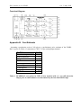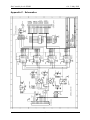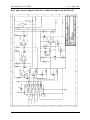
1
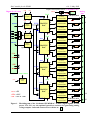
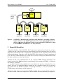
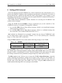
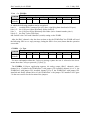
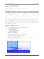
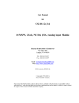
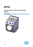
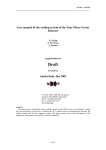
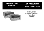
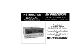
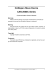
DAC-module for the ELMB
v1.0 3-May-2002
ELMB-DAC
16-channel
12-bit DAC-module
for the ELMB
user manual, version 1.0
3 May 2002
Jaap Kuijt, Paul Timmer, Björn Hallgren, Piet de Groen,
Daniel Tascon Lopez, Sander Schouten, Henk Boterenbrood
Amsterdam, NL
Table of Contents
1
INTRODUCTION .............................................................................................................. 2
2
HARDWARE DESCRIPTION ......................................................................................... 2
3
SPEED OF OPERATION ................................................................................................. 5
4
SETTING A DAC-CHANNEL ......................................................................................... 6
5
CONNECTORS AND JUMPERS .................................................................................... 8
REFERENCES ........................................................................................................................ 10
APPENDIX A.
MAX525 DAC ............................................................................................ 11
DESCRIPTION .......................................................................................................................... 11
KEY FEATURES AND SPECIFICATIONS ..................................................................................... 11
FUNCTIONAL DIAGRAM .......................................................................................................... 12
APPENDIX B. COST ESTIMATE .................................................................................... 12
APPENDIX C.
SCHEMATICS .......................................................................................... 13
1
DAC-module for the ELMB
v1.0 3-May-2002
1 Introduction
This document describes the ELMB-DAC (Digital -to-Analog Converter) module and how
to use it. The ELMB-DAC is a general-purpose DAC-module but was developed specifically
to provide analog output capabilities to the ELMB module [1] plugged on its standard Motherboard. It connects directly to the 20-pin J8 connector of this motherboard. Up to
four ELMB-DACs can be connected to (and powered by) one ELMB.
The PCB of the ELMB-DAC can be fitted in a green box in the same way as an ELMB
Motherboard does. All connectors are located at the front of the PCB.
The standard CANopen ([1]) software for the ELMB+motherboard (ELMBio version 3.5,
[3]) supports up to four ELMB-DACs, thus providing a total of 64 12-bit analog output cha nnels. Both current or voltage output is possible.
The ELMB-DAC can be used in other systems and by other controllers (non-ELMB) as
well, since it is controlled through a simple serial interface (3-wire plus a select-signal).
2 Hardware Description
Summary:
• 16 channels @ 12-bit using four 12-bit 4-channel MAX525 ICs ([4], and also see
Appendix A. MAX525) digitally daisy-chained (Two different versions of MAX525 are
available: MAX525A with 0.5 LSB 'Integral Nonlinearity', or MAX525B with 1.0 LSB
'Integral Nonlinearity').
• Controlled through a 3-wire serial interface, opto-isolated from the controller, with
HCPL-0731 type optocouplers.
• One-of- five module-select signal selectable by jumper, also opto-isolated.
• Current output 0-20 mA, or 0-1 mA, depending on the value of one onboard resistor per
channel.
• Output accuracy depends on the precision of installed resistors, i.e. 1% or 0.1%.
• Space for optional DIL resistor packages in case voltage output is required.
• Power:
o Optocouplers: powered by the +3.3V supplied on the 'digital' connector (from the
ELMB, ca. 5 mA)
o DAC digital circuitry: powered by the +5V supplied on the 'digital' connector (from
the ELMB, ca. 5 mA)
o Current-output circuitry: powered externally via a separate connection to a powersupply VE or -with restrictions- by the +5V supplied from the 'digital' connector (from the
ELMB), selectable by jumpers.
o Current output 0-20 mA: output circuits must be powered by the separate external
powersupply VE (5 to 30V), if an ELMB is the controller of the DAC.
Voltage output: ca.(VE-2.5) Volts maximum (there is also a minimum, see below).
o Current output 0-1 mA: output circuit can be powered either from +5V (from the
ELMB) or an external powersupply.
If the ELMB is used for powering (5V), the voltage output can be ca. 2.5V maximum.
2
DAC-module for the ELMB
v1.0 3-May-2002
Figure 1 below shows a blockdiagram of the ELMB-DAC. Note the jumper block used to set
a module ‘address’, and the jumper selecting the power for the current output circuitry. Beware: it is always necessary to use a separate external powersupply VE for 0-20 mA current
output: an ELMB is not capable to supply enough current.
The external powersupply voltage VE can be in the range of +5V to +30V but some care
must be taken to protect the output circuit from overdissipation. The dissipation in the output
FET should be limited to ca. 200 mW (FET datasheet: 600 mW max).
So for output current I=20mA, the voltage across the FET should not exceed
200mW/20mA=10V. The dissipation D in the FET is described by the following formula:
D=I*(V E-2.2) Watts. This means that either VE<12.2V or that the external load has a voltage
drop of at least (VE-12.2) Volts or, in other words, represent a minimum load of (VE-12.2)/20
kΩ.
For example: for a 15V powersupply the output load should be at least 2.8/20 kΩ = 140 Ω.
So for supply voltages of about 12V and higher a minimum load is required, if 20 mA output
current is used. For 1 mA output current no minimum load is required.
Table 1 summarizes the load requirements of the ELM B-DAC module.
Output
[mA]
0-20 mA
0-1 mA
Min. Load
[kΩ ]
(VE-12.2)/20
0
Max. Load
[kΩ ]
(VE-2.2)/20
VE-2.2
Table 1. ELMB-DAC load requirements (per channel).
When an ELMB powers the ELMB-DAC VE=5V
(i.e. max. load at 1 mA is 2.8 kΩ ).
The DOUT signal is not essential (it can only serve as a data echo) and the optocoupler for
this signal could be left uninstalled.
Figure 2 shows how 4 ELMB-DACs can be connected to an ELMB+Motherboard system.
3
DAC-module for the ELMB
Digital In (+Po wer)
+VD
DIN
+VA
Opto
coupler
+VD
SCLK
+VA
Opto
coupler
+VD
CS0
CS1
CS2
CS3
CS4
oo
oo
oo
DIN
+VA
Opto
coupler
v1.0 3-May-2002
output circuit power select External Po we r
Analog
oo
+VE
+VA
AGND
Out
Vref
0-20 (0-1) mA
U-to-I
0
R
conversion
A
B
SCLK MAX525
DAC
C
D
CS
DOUT
+VA
Vref
oo
address
+VD
DOUT
DIN
+VA
A
Opto
coupler
(optional)
B
SCLK MAX525
DAC
C
D
CS
+VA
DOUT
AGND
+VA
Vref
DIN
A
+VD
DGND
Vref (+2.5V)
+VA
B
SCLK MAX525
DAC
D
CS
DOUT
AD680
Vref
C
+VA
Vref
DIN
A
SCLK
+VA : +5V
+VD : +3.3V
+VE : +5V to +30V
MAX525
DAC
B
C
D
CS
DOUT
+VA
U-to-I
conversion
AGND
R
U-to-I
conversion
R
U-to-I
conversion
R
U-to-I
conversion
R
U-to-I
conversion
R
U-to-I
conversion
R
U-to-I
conversion
R
U-to-I
conversion
R
U-to-I
conversion
R
U-to-I
conversion
R
U-to-I
conversion
R
U-to-I
conversion
R
U-to-I
conversion
R
U-to-I
conversion
R
U-to-I
conversion
0-20 (0-1) mA
R
AGND
Figure 1. Blockdiagram of the 16-channel ELMB-DAC. In blue: digital signals, in red:
power. The ‘R’s are the optional (precision) resistors for generating analog
voltage outputs. Onboard connectors are shown as:
4
1
14
15
DAC-module for the ELMB
v1.0 3-May-2002
CAN
J8
ELMB
SCLK, DIN,
DOUT,
4 * CS,
power
Motherboard
ELMB
DAC
ELMB
DAC
ELMB
DAC
analog out
chan 0-15
analog out
chan 16-31
analog out
chan 32-47
ELMB
DAC
analog out
chan 48-63
Figure 2. An ELMB + Motherboard system with 4 ELMB-DACs, providing 64 analog
output channels to the ELMB application. The select-signal jumper block is
shown as:
(note the different setting on the individual ELMB-DACs, which
is essential when ELMB-DACs are daisy-chained).
3 Speed of Operation
The serial interface of the MAX525 DAC-chip can be operated at a clock rate of up to
10 MHz, but due to the (low-power/slow) optocouplers used in the board design, the speed at
which the serial interface can be operated is very limited: the bit frequency cannot exceed
6 kHz or thereabouts. In practice –with four MAX525 daisy chained– it means a maximum of
up to 100 DAC-channel updates per second can be achieved. Having 64 channels this means
less than 2 updates per second per cha nnel.
Because of this it is recommended to use the CANopen SDO message mechanism (confirmed) instead of the PDO mechanism (unconfirmed), when using the ELMB + CAN(open).
See section 3 for details.
A new DAC-channel setting should not be issued before the previous setting has been confirmed. This way it is guaranteed that no settings are lost. (Actually the host can run one message ahead since the ELMB can buffer one message currently…; in a next version of the
ELMB software this situation will be improved).
Without or with faster optocouplers the ELMB would be able to sustain a DAC-channel update rate of about 10 KHz (as compared to 100 Hz with the currently installed optocouplers).
5
DAC-module for the ELMB
v1.0 3-May-2002
4 Setting a DAC-channel
Users who intend to use the ELMB-DAC by a direct connection to the serial interface are referred to the MAX525 datasheet ([4]) for details on operating the serial interface. Be aware of
the fact that the DAC- module has four MAX525 DACs daisy-chained ! (For example: to write
something to the last DAC in the chain, write the required MAX525 command, followed by 3
socalled NOP (No Operation) commands).
The ELMB software distribution contains functions for accessing the ELMB-DAC and
could be used as example.
Using the ELMB and the ELMBio CANopen application ([3]) as the controller of the
ELMB-DACs there are 2 methods of setting DAC-channels:
1. by a socalled PDO (Process Data Object) message, which is an unconfirmed message,
with no protocol overhead, or
2. by a socalled SDO (Service Data Object) message, which is a confirmed message (the
user is the SDO client and the ELMB is the SDO server).
Both methods are illustrated by an example. Assume the user has an ELMB-DAC with
0-1 mA output and he wants to set DAC-channel 13 to 0.5 mA (half-way the 12-bits data
range, i.e. write value 0x7FF to the DAC).
Using the PDO method the user wo uld send the following message to the ELMB:
User → ELMBio
RPDO2 COB-ID
0x300+NodeID
DataByte 0
(Channel Number)
0x0D
DataByte 2-3
(DAC value)
0x7FF
in which RPDO stands for Receive-PDO (the CANopen application is a receiver of this PDO)
and NodeId is the CAN node identifier (switch) setting on the ELMB. There is no reply to this
message (a PDO is unconfirmed). It is the CANopen method of fast data transport, in which
the message content has been predefined and agreed upon by sender and receiver(s).
The SDO method is the CANopen way to access the ELMB's Object Dictionary –basically
a table containing all parameters, settings and I/O points of the CANopen node (ELMB)– on
the basis of an index and a sub-index. The one accessing the table is the client (here: the user)
and the owner of the table (here: the ELMB) is the server. Using the SDO method the user
would send the following SDO client message to the ELMB:
6
DAC-module for the ELMB
User
v1.0 3-May-2002
→
ELMBio
DataByte
COB-ID
0
1
0x600+
0x2B 0x11
NodeID
2
0x64
3
0x0E
4
0xFF
5
0x07
6
0x00
7
0x00
in which the following numbers can be recognized:
byte 0:
socalled SDO Command Specifier (here: signifying data download of 2 bytes)
byte 1+2: the CANopen Object Dictionary Index (0x6411).
byte 3:
the CANopen Object Dictionary Sub-Index (here: channel number plus 1).
byte 4+5: the DAC value (LSB first),
and NodeId is the CAN node identifier (switch) setting on the ELMB.
After the DAC-channel value has been written to the the ELMB-DAC the ELMB will send
the following SDO server reply message, letting the SDO client (user) know that the operation
succeeded:
ELMBio
COB-ID
0x580+
NodeID
→
User
DataByte
0
1
0x60
0x11
2
0x64
3
0x0E
4
0x00
5
0x00
6
0x00
7
0x00
For more information about the CANopen message syntax the user is referred to the documents about the CANopen protocol ([2] and [3]).
The ELMBio CANopen application supports 64 analog output (DAC) channels, where
channel 0 to 15 address the ELMB-DAC with jumper CS0 installed, channel 16 to 31 the
ELMB-DAC with jumper CS1 installed, channel 32 to 47 the ELMB-DAC with jumper CS2
installed and finally channel 48 to 63 the ELMB-DAC with jumper CS3 installed. See Figure
3 in the next section for the location of the jumpers.
7
DAC-module for the ELMB
v1.0 3-May-2002
5 Connectors and Jumpers
In Figure 3 pictures of the module's front- and backside are shown with connectors, jumpers,
etc. indicated.
Pin 1
-VE
+VE
External
Power VE
Connector
Analog-Out
Connector
Digital-in
Connector
Socket for
DIL-resistor
package
(channel 8-15)
Pin 1
Socket for
DIL-resistor
package
(channel 0-7)
Address Selection
Jumper Block,
from bottom to top:
CS0, CS1, CS2, CS3
and CS4 resp.
Power Selection Jumper
Block for output circuits,
from bottom to top
2 jumpers for chan 0-3,
2 jumpers for chan 4-7,
2 jumpers for chan 8-11,
2 jumpers for chan 12-15
(shown here: all cha nnels take
power from VE connector)
if jumper installed:
channel 0-3 powered by VE
channel 0-3 powered by
+5V on dig ital-in connector
Figure 3. Front- and backside of the ELMB-DAC module.
8
DAC-module for the ELMB
v1.0 3-May-2002
Table 2 presents the layout of the pins of the digital- in connector, and Table 3 of the analogout connector.
Table 2.
Table 3.
not connected
20
19
not connected
SCLK (from ELMB PD4)
18
17
not connected
DIN (from ELMB PD5)
16
15
CS4 (from ELMB PE7)
DOUT (to ELMB PD6)
14
13
CS3 (from ELMB PE6)
CS2 (from ELMB PE5)
12
11
CS1 (from ELMB PE4)
CS0 (from ELMB PE3)
10
9
not connected
not connected
8
7
DGND in
DGND in
6
5
+3.3V (+VD) in
+5V (+VA) in
4
3
not used (from ELMB -5VA)
AGND in
2
1
AGND in
ELMB-DAC digital-in connector pin description.
not connected
26
25
not connected
not connected
24
23
AGND
Aout 15
22
21
Aout 14
Aout 13
20
19
Aout 12
not connected
18
17
AGND
Aout 11
16
15
Aout 10
Aout 9
14
13
Aout 8
not connected
12
11
AGND
Aout 7
10
9
Aout 6
Aout 5
8
7
Aout 4
not connected
6
5
AGND
Aout 3
4
3
Aout 2
Aout 1
2
1
Aout 0
ELMB-DAC analog-out connector pin description.
9
DAC-module for the ELMB
v1.0 3-May-2002
References
[1] Embedded Local Monitor Board,
CERN, May 2000,
(http://atlasinfo.cern.ch/ATLAS/GROUPS/DAQTRIG/DCS/ELMB/elmb.html).
[2] H.Boterenbrood,
CANopen, high-level protocol for CAN-bus,
Version 3.0, NIKHEF, Amsterdam, 20 March 2000.
(http://www.nikhef.nl/pub/departments/ct/po/doc/CANopen30.pdf).
[3] H.Boterenbrood,
Software for the ELMB CANopen module,
Version 1.5, NIKHEF, Amsterdam, 10 January 2002.
(http://www.nikhef.nl/pub/departments/ct/po/doc/ELMB15.pdf).
[4] Low-Power, Quad, 12-bit Voltage Output DAC with Serial Interface,
MAXIM product datasheet, 19-1098 Rev 1, Dec 1996,
(http://www.maxim- ic.com/).
10
DAC-module for the ELMB
v1.0 3-May-2002
Appendix A. MAX525 DAC
(A brief description taken from the manufacturer's website).
Description
The MAX525 combines four low-power, voltage-output, 12-bit digital-to-analog converters
(DACs) and four precision output amplifiers in a space-saving, 20-pin package. In addition to
the four voltage outputs, each amplifier's negative input is also available to the user. This facilitates specific gain configurations, remote sensing, and high output drive capacity, making
the MAX525 ideal for industrial-process-control applications. Other features include software
shutdown, hardware shutdown lockout, an active- low reset which clears all registers and
DACs to zero, a user-programmable logic output, and a serial-data output.
Each DAC has a double-buffered input organized as an input register followed by a DAC register. A 16-bit serial word loads data into each input/DAC register. The serial interface is compatible with SPI™/QSPI™ and Microwire™. It allows the input and DAC registers to be
updated independently or simultaneously with a single software command. The DAC registers
can be simultaneously updated via the 3-wire serial interface. All logic inputs are
TTL/CMOS-logic compatible.
Key Features and Specifications
Features:
• Four 12-Bit DACs with Configurable Output Amplifiers
• +5V Single-Supply Operation
• Low Supply Current:
§ 0.85mA Normal Operation
§ 10µA Shutdown Mode
• Available in 20-Pin SSOP
• Power-On Reset Clears all Registers and DACs to Zero
• Capable of Recalling Last State Prior to Shutdown
• SPI/QSPI and Microwire Compatible
• Simultaneous or Independent Control of DACs via 3-Wire Serial Interface
• User-Programmable Digital Output
Specifications:
Data Bus Interface
Resolution (Bits)
Number of DACs
Supply Voltage (V)
Typ. Supply Current (mA)
Output Type
Typ. Settling Time (µs)
Reference
Operating Range
Package
Price @ 1k
3-wire Serial
12
4
+5
0.85
Voltage
12
External
-40 to +85, -55 to 125, 0 to +70
20/PDIP.300, 20/SSOP
$11,95
11
DAC-module for the ELMB
v1.0 3-May-2002
Functional Diagram
Appendix B. Cost Estimate
Assuming a production series of 100 pieces, a (preliminary) price estimate of the ELMBDAC is given in Table 4. It amounts to CHF 17.50 per analog output channel.
PARTS
Passive components
Semiconductors
Connectors
PCB
Assembly
Contingency
TOTAL
COST
1
154
13
(?) 20
(?) 60
30
278
Table 4. ELMB-DAC cost (prices in CHF). Prices marked with '(?)' are still uncertain.
Major part of semiconductor cost determined by the four MAX525B chips.
12
DAC-module for the ELMB
v1.0 3-May-2002
Appendix C. Schematics
13
DAC-module for the ELMB
v1.0 3-May-2002
DAC and current output circuit for 4 channels (times 4 on the board):
14