Download Digitax ST Tech Data Guide English Issa.book
Transcript
efesotomasyon.com - Control Techniques,emerson,saftronics -ac drive-servo motor
4186 en - 2008.07 / a
0V common
External 24V supply
1
2
Analog speed
reference 1
0V common
Connections for
single-ended input
signal
3
5
6
0V common
Connections for
differential input signal
4
Analog
speed
reference 2
i ven
be g
o
t
s
ide i d user
u
g
en
This
e
h
t
to
7
8
Analog input 3
Motor thermistor
9
Speed
10
Torque (active
current)
11
0V common
0V common
21
22
0V common
23
At zero speed
24
Reset
25
Run forward
Run reverse
Analog input 1/
input 2 select
26
27
Analog input 1
Analog input 2
Jog forward select
28
29
0V common
30
SECURE DISABLE INPUT /
Drive enable
31
Status relay
41
Drive OK
42
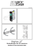
Variable speed drive for servomotors
Technical data guide
efesotomasyon.com - Control Techniques,emerson,saftronics -ac drive-servo motor
General Information
The manufacturer accepts no liability for any consequences resulting from inappropriate, negligent or incorrect
installation or adjustment of the optional operating parameters of the equipment or from mismatching the variable speed
drive with the motor.
The contents of this guide are believed to be correct at the time of printing. In the interests of a commitment to a policy
of continuous development and improvement, the manufacturer reserves the right to change the specification of the
product or its performance, or the contents of the guide, without notice.
All rights reserved. No parts of this guide may be reproduced or transmitted in any form or by any means, electrical or
mechanical including photocopying, recording or by an information storage or retrieval system, without permission in
writing from the publisher.
Drive software version
This product is supplied with the latest version of software. If this product is to be used in a new or existing system with
other drives, there may be some differences between their software and the software in this product. These differences
may cause this product to function differently. This may also apply to drives returned from a LEROY-SOMER Service
Centre.
The software version of the drive can be checked by looking at Pr 11.29 (or Pr 0.50) and Pr 11.34. The software version
takes the form of zz.yy.xx, where Pr 11.29 displays zz.yy and Pr 11.34 displays xx, i.e. for software version 01.01.00,
Pr 11.29 would display 1.01 and Pr 11.34 would display 0.
If there is any doubt, contact LEROY-SOMER.
Environmental statement
LEROY-SOMER is committed to minimising the environmental impacts of its manufacturing operations and of its
products throughout their life cycle. To this end, we operate an Environmental Management System (EMS) which is
certified to the International Standard ISO 14001.
The electronic variable-speed drives manufactured by LEROY-SOMER have the potential to save energy and (through
increased machine/process efficiency) reduce raw material consumption and scrap throughout their long working
lifetime. In typical applications, these positive environmental effects far outweigh the negative impacts of product
manufacture and end-of-life disposal.
Nevertheless, when the products eventually reach the end of their useful life, they can very easily be dismantled into their
major component parts for efficient recycling. Many parts snap together and can be separated without the use of tools,
while other parts are secured with conventional screws. Virtually all parts of the product are suitable for recycling.
Product packaging is of good quality and can be re-used. Large products are packed in wooden crates, while smaller
products come in strong cardboard cartons which themselves have a high recycled fibre content. If not re-used, these
containers can be recycled. Polythene, used on the protective film and bags for wrapping product, can be recycled in the
same way. LEROY-Somer's packaging strategy favours easily-recyclable materials of low environmental impact, and
regular reviews identify opportunities for improvement.
When preparing to recycle or dispose of any product or packaging, please observe local legislation and best practice.
efesotomasyon.com - Control Techniques,emerson,saftronics -ac drive-servo motor
Contents
1
Introduction ...........................................4
2
Product ratings ......................................5
2.1
2.2
2.3
2.4
2.5
2.6
2.7
2.8
2.9
2.10
2.11
Model number .......................................................5
Nameplate description ..........................................5
Drive ratings ..........................................................5
Typical pulse duty .................................................5
Continuous rating ..................................................9
Maximum power ratings ........................................9
Maximum drive losses ........................................10
Motor cable size and maximum lengths ..............10
Braking ................................................................10
AC input ratings ..................................................11
DC drive voltage levels .......................................11
3
Drive dimensions ................................13
4
I/O Specification ..................................14
4.1
4.2
4.3
Control terminals .................................................14
Encoder terminals ...............................................17
Serial communications connections ....................20
5
EMC filters ...........................................21
5.1
5.2
External EMC filter rating ....................................21
Internal and external conducted emissions
conformity ...........................................................21
6
Options .................................................22
7
General data ........................................24
8
Diagnostics ..........................................25
8.1
8.2
Alarm indications .................................................38
Status indications ................................................39
Digitax ST Technical Data Guide
Issue: a
3
www.leroy-somer.com
efesotomasyon.com - Control Techniques,emerson,saftronics -ac drive-servo motor
Introduction
1
Product ratings
Drive
dimensions
I/O
Specification
EMC filters
Options
General data
Diagnostics
Index
Introduction
Three different configurations of the Digitax ST servo drive are available:
•
•
•
Digitax ST Base
Digitax ST Indexer
Digitax ST Plus
The Digitax ST Base drive operates in velocity or torque modes and is
designed to operate with a centralized motion controller or as a
standalone drive.
The Digitax ST Indexer drive performs point-to-point motion profiling
including relative, absolute, rotary plus, rotary minus, registration and
homing motion. The Digitax ST Indexer will operate as a single
standalone system controller. Alternatively, the Digitax ST Indexer can
form part of a distributed system where commands are sent over a
fieldbus or through digital input/output signals.
The Digitax ST Plus drive offers the option of executing complex
movements on a single axis or synchronised movements in relation to a
reference axis. It also offers synchronisation and electronic cam
functions with management of the virtual master.
All configurations offer a SECURE DISABLE INPUT function . (Refer to
the Installation guide, paragraph 1)
4
www.leroy-somer.com
Digitax ST Technical Data Guide
Issue: a
efesotomasyon.com - Control Techniques,emerson,saftronics -ac drive-servo motor
Product
ratings
Introduction
Drive
dimensions
2
Product ratings
2.1
Model number
Figure 2-1
I/O
Specification
EMC filters
Options
2.3
Model code explanation
These systems come into operation under various extremes of operating
conditions. (I.e. ambient, supply imbalance, output power.)
2.3.1
Maximum ratings
Maximum ratings
Rated current
Voltage rating
M : 200V to 240V Single phase
TL: 200V to 240V Three phase
T : 380V to 480V Three phase
Configuration
B: Base
I: Indexer
P: Plus
Nameplate description
Peak current
IMAX
A
Model
1ph
3ph
1ph
ST 1.1A M/TL
1 or 3
1.1
1.7
2.2
5.1
ST 2.4A M/TL
1 or 3
2.4
3.8
4.8
11.4
ST 2.9A M/TL
1 or 3
2.9
5.4
5.8
16.2
ST 4.7A M/TL
1 or 3
4.7
7.6
9.4
22.8
ST 1.5A T
3
1.5
ST 2.7A T
3
2.7
8.1
ST 4.0A T
3
4.0
12.0
ST 5.9 A T
3
5.9
17.7
ST 8.0A T
3
8.0
24.0
3ph
4.5
The rating information shown in section 2.4 Typical pulse duty is based
on the limitations of the drive output stage only.
Typical approvals label
Rating label
*The ratings are based on the following operating conditions:
Frequency Serial
number
S/N: 3000005001
I/P 200-240V 50-60Hz
1/3ph 4.0/3.1A
O/P 0-240V ST 1.1A M/TL 3ph 2.2/5.1Apk
Output voltage
range
Motor
output
Single/three
phase input current
Single/three phase
peak output current
Commercial ref
Ambient temperature = 40°C
Altitude = 1000m
Not exceeding power ratings stated in Table 2-12 on page 9
DC bus voltage = 565V for ST X.XA T
DC bus voltage = 325V for ST X.XA M/TL
The sizing tool should be used to select a drive for a profile or condition
that is not given as an example in section 2.4 Typical pulse duty .
2.4
Approvals label
2.2/5.1Apk
Date code
250ms
The profiles simulate the drive accelerating from standstill to full speed.
2.4.1
Q23
Repetitive profile with defined level of Ipeak
Figure 2-3
Please read the manual before connecting
Electric Shock Risk: Wait 10 mins between
disconnecting supply and accessing terminals
S/N:2072300007
ST 1.1A M/TL
Typical pulse duty
The following tables give examples of load profiles that indicate the
performance of the drive.
Rating
Type
DST1201
•
•
•
•
•
Approval
Current (A)
Type
Serial
number
Nominal current
In
A
No of input
phases
Model: Digitax ST
Input
voltage
Index
Drive ratings
Table 2-1
Figure 2-2
Diagnostics
The drive rating is limited by numerous systems which protect the power
stage hardware. (Rectifier, DC bus, inverter)
ST 1.1A M/TL B
2.2
General data
Commercial ref
Repetitive profile with defined level of Ipeak
IMax
Ipeak
In
Tpeak
Speed
Time
Tduty
Time
This is a profile with acceleration/deceleration periods where the peak
output current from the drive (Ipeak) is given as a proportion of the
nominal current (In) for a defined period of time. (Tpeak).
For example accelerating/decelerating for 10s with a current of 2.0 x In.
Digitax ST Technical Data Guide
Issue: a
5
www.leroy-somer.com
efesotomasyon.com - Control Techniques,emerson,saftronics -ac drive-servo motor
Introduction
Product
ratings
Drive
dimensions
I/O
Specification
EMC filters
The ratio between accelerating/decelerating period (Tpeak) and the total
profile period (Tduty) is always 1:10.
Options
General data
Diagnostics
Index
The profile shows the level of current that can be provided during the
running/stopped period when the maximum peak current is used for
accelerating/decelerating.
Ibase is the drive output current during the constant speed segment of the
profile.
Table 2-2
Repetitive profile with defined level of Ipeak at 6kHz switching frequency, ≤230Vac supply for ST X.XA M/TL and ≤400Vac supply
for ST X.XA T
Overloads
In
Model
1.5 x In for 60s
1.75 x In for 40s
2.0 x In for 10s
Ibase
Ipeak
Ibase
Ipeak
Ibase
2.5 x In for 2s
3.0 x In for 0.25s
Ipeak
Ibase
Ipeak
Ibase
Ipeak
A
ST 1.1A M/TL
1.7
1.7
2.6
1.7
3.0
1.7
3.4
1.7
4.3
1.7
5.1
ST 2.4A M/TL
3.8
3.8
5.7
3.8
6.7
3.8
7.6
3.8
9.5
3.8
11.4
ST 2.9A M/TL
5.4
5.4
8.1
5.4
9.5
5.4
10.8
5.4
13.5
5.4
16.2
ST 4.7A M/TL
7.6
7.6
11.4
7.6
13.3
7.6
15.2
7.6
19.0
7.6
22.8
ST 1.5A T
1.5
1.5
2.3
1.5
2.6
1.5
3.0
1.5
3.8
1.5
4.5
ST 2.7A T
2.7
2.7
4.1
2.7
4.7
2.7
5.4
2.7
6.8
2.7
8.1
ST 4.0A T
4.0
4.0
6.0
4.0
7.0
4.0
8.0
4.0
10.0
4.0
12.0
ST 5.9A T
5.9
5.9
8.9
5.9
10.3
5.9
11.8
5.9
14.8
5.9
17.7
ST 8.0A T
8.0
6.5
12.0
6.8
14.0
8.0
16.0
8.0
20.0
8.0
24.0
Table 2-3
Repetitive profile with defined level of Ipeak at 8kHz switching frequency, ≤230Vac supply for ST X.XA M/TL and ≤400Vac supply
for ST X.XA T
Overloads
In
Model
1.5 x In for 60s
1.75 x In for 40s
2.0 x In for 10s
Ibase
Ipeak
Ibase
Ipeak
Ibase
2.5 x In for 2s
3.0 x In for 0.25s
Ipeak
Ibase
Ipeak
Ibase
Ipeak
A
ST 1.1A M/TL
1.7
1.7
2.6
1.7
3.0
1.7
3.4
1.7
4.3
1.7
5.1
ST 2.4A M/TL
3.8
3.8
5.7
3.8
6.7
3.8
7.6
3.8
9.5
3.8
11.4
ST 2.9A M/TL
5.4
5.4
8.1
5.4
9.5
5.4
10.8
5.4
13.5
5.4
16.2
ST 4.7A M/TL
7.6
7.6
11.4
7.6
13.3
7.6
15.2
7.6
19.0
7.6
22.8
ST 1.5A T
1.5
1.5
2.3
1.5
2.6
1.5
3.0
1.5
3.8
1.5
4.5
ST 2.7A T
2.7
2.7
4.1
2.7
4.7
2.7
5.4
2.7
6.8
2.7
8.1
ST 4.0A T
4.0
4.0
6.0
4.0
7.0
4.0
8.0
4.0
10.0
4.0
12.0
ST 5.9A T
5.9
4.4
8.9
4.4
10.3
5.9
11.8
5.9
14.8
5.9
17.7
ST 8.0A T
8.0
1.8
12.0
3.2
14.0
6.9
16.0
7.0
20.0
7.3
24.0
Table 2-4
Repetitive profile with defined level of Ipeak at 6kHz switching frequency, ≤240Vac supply for ST X.XA M/TL and ≤480Vac supply
for ST X.XA T
Overloads
Model
In
1.5 x In for 60s
1.75 x In for 40s
2.0 x In for 10s
Ibase
Ipeak
Ibase
Ipeak
Ibase
2.5 x In for 2s
3.0 x In for 0.25s
Ipeak
Ibase
Ipeak
Ibase
Ipeak
A
ST 1.1A M/TL
1.7
1.7
2.6
1.7
3.0
1.7
3.4
1.7
4.3
1.7
5.1
ST 2.4A M/TL
3.8
3.8
5.7
3.8
6.7
3.8
7.6
3.8
9.5
3.8
11.4
ST 2.9A M/TL
5.4
5.4
8.1
5.4
9.5
5.4
10.8
5.4
13.5
5.4
16.2
ST 4.7A M/TL
7.6
7.6
11.4
7.6
13.3
7.6
15.2
7.6
19.0
7.6
22.8
ST 1.5A T
1.5
1.5
2.3
1.5
2.6
1.5
3.0
1.5
3.8
1.5
4.5
ST 2.7A T
2.7
2.7
4.1
2.7
4.7
2.7
5.4
2.7
6.8
2.7
8.1
ST 4.0A T
4.0
4.0
6.0
4.0
7.0
4.0
8.0
4.0
10.0
4.0
12.0
ST 5.9A T
5.9
5.9
8.9
5.9
10.3
5.9
11.8
5.9
14.8
5.9
17.7
ST 8.0A T
8.0
5.5
12.0
5.8
14.0
8.0
16.0
8.0
20.0
8.0
24.0
6
www.leroy-somer.com
Digitax ST Technical Data Guide
Issue: a
efesotomasyon.com - Control Techniques,emerson,saftronics -ac drive-servo motor
Introduction
Table 2-5
Product
ratings
Drive
dimensions
I/O
Specification
EMC filters
Options
General data
Diagnostics
Index
Repetitive profile with defined level of Ipeak at 8kHz switching frequency, ≤240Vac supply for ST X.XA M/TL and ≤480Vac supply
for ST X.XA T
Overloads
Model
In
1.5 x In for 60s
Ibase
Ipeak
1.75 x In for 40s
2.0 x In for 10s
Ibase
Ibase
Ipeak
2.5 x In for 2s
3.0 x In for 0.25s
Ipeak
Ibase
Ipeak
Ibase
Ipeak
A
ST 1.1A M/TL
1.7
1.7
2.6
1.7
3.0
1.7
3.4
1.7
4.3
1.7
5.1
ST 2.4A M/TL
3.8
3.8
5.7
3.8
6.7
3.8
7.6
3.8
9.5
3.8
11.4
ST 2.9A M/TL
5.4
5.4
8.1
5.4
9.5
5.4
10.8
5.4
13.5
5.4
16.2
ST 4.7A M/TL
7.6
7.6
11.4
7.6
13.3
7.6
15.2
7.6
19.0
7.6
22.8
ST 1.5A T
1.5
1.5
2.3
1.5
2.6
1.5
3.0
1.5
3.8
1.5
4.5
ST 2.7A T
2.7
2.7
4.1
2.7
4.7
2.7
5.4
2.7
6.8
2.7
8.1
ST 4.0A T
4.0
4.0
6.0
4.0
7.0
4.0
8.0
4.0
10.0
4.0
12.0
ST 5.9A T
5.9
3.6
8.9
3.6
10.3
5.9
11.8
5.9
14.8
5.6
17.7
ST 8.0A T
8.0
1.3
12.0
2.5
14.0
5.8
16.0
6.2
20.0
6.1
24.0
2.4.2
Repetitive profile with defined ratio between
Ibase to Ipeak
Current (A)
Figure 2-4 Repetitive profile with defined ratio between Ibase to Ipeak
IMax
Ipeak
Tpeak
Speed
Time
Tduty
Time
This is a profile with acceleration/deceleration periods where the peak
output current from the drive (Ipeak) is given as a proportion of the base
current (Ibase) for a defined period of time. (Tpeak).
For example accelerating/decelerating for 10s with a current of 2.0 x
Ibase.
The ratio between accelerating/decelerating period (Tpeak) and the total
profile period (Tduty) is always 1:10.
The profile shows the highest Ibase ratings possible for the given Ipeak/
Ibase ratio.
Digitax ST Technical Data Guide
Issue: a
7
www.leroy-somer.com
efesotomasyon.com - Control Techniques,emerson,saftronics -ac drive-servo motor
Introduction
Table 2-6
Product
ratings
Drive
dimensions
I/O
Specification
EMC filters
Options
General data
Diagnostics
Index
Repetitive profile with defined ratio between Ibase to Ipeak at 6kHz switching frequency, ≤230Vac supply for ST X.XA M/TL and
≤400Vac supply for ST X.XA T
Overloads
In
Model
1.5 x Ibase for 60s
Ibase
Ipeak
1.75 x Ibase for 40s
Ibase
Ipeak
2.0 x Ibase for 10s
Ibase
2.5 x Ibase for 2s
3.0 x Ibase for 0.25s
Ipeak
Ibase
Ipeak
Ibase
Ipeak
A
ST 1.1A M/TL
1.7
1.7
2.6
1.7
3.0
1.7
3.4
1.7
4.3
1.7
5.1
ST 2.4A M/TL
3.8
3.8
5.7
3.8
6.7
3.8
7.6
3.8
9.5
3.8
11.4
ST 2.9A M/TL
5.4
5.4
8.1
5.4
9.5
5.4
10.8
5.4
13.5
5.4
16.2
ST 4.7A M/TL
7.6
7.6
11.4
7.6
13.3
7.6
15.2
7.6
19.0
7.6
22.8
ST 1.5A T
1.5
1.5
2.3
1.5
2.6
1.5
3.0
1.5
3.8
1.5
4.5
ST 2.7A T
2.7
2.7
4.1
2.7
4.7
2.7
5.4
2.7
6.8
2.7
8.1
ST 4.0A T
4.0
4.0
6.0
4.0
7.0
4.0
8.0
4.0
10.0
4.0
12.0
ST 5.9A T
5.9
5.9
8.9
5.9
10.3
5.9
11.8
5.9
14.8
5.9
17.7
ST 8.0A T
8.0
7.6
11.4
7.6
13.3
8.0
16.0
8.0
20.0
8.0
24.0
Table 2-7
Repetitive profile with defined ratio between Ibase to Ipeak at 8kHz switching frequency, ≤230Vac supply for ST X.XA M/TL and
≤400Vac supply for ST X.XA T
Overloads
In
Model
1.5 x Ibase for 60s
1.75 x Ibase for 40s
2.0 x Ibase for 10s
Ibase
Ipeak
Ibase
Ipeak
Ibase
2.5 x Ibase for 2s
3.0 x Ibase for 0.25s
Ipeak
Ibase
Ipeak
Ibase
Ipeak
A
ST 1.1A M/TL
1.7
1.7
2.6
1.7
3.0
1.7
3.4
1.7
4.3
1.7
5.1
ST 2.4A M/TL
3.8
3.8
5.7
3.8
6.7
3.8
7.6
3.8
9.5
3.8
11.4
ST 2.9A M/TL
5.4
5.4
8.1
5.4
9.5
5.4
10.8
5.4
13.5
5.4
16.2
ST 4.7A M/TL
7.6
7.6
11.4
7.6
13.3
7.6
15.2
7.6
19.0
7.6
22.8
ST 1.5A T
1.5
1.5
2.3
1.5
2.6
1.5
3.0
1.5
3.8
1.5
4.5
ST 2.7A T
2.7
2.7
4.1
2.7
4.7
2.7
5.4
2.7
6.8
2.7
8.1
ST 4.0A T
4.0
4.0
6.0
4.0
7.0
4.0
8.0
4.0
10.0
4.0
12.0
ST 5.9A T
5.9
5.6
8.4
5.6
9.8
5.9
11.8
5.9
14.8
5.9
17.7
ST 8.0A T
8.0
6.0
9.0
6.0
10.5
7.6
15.2
7.6
19.0
7.6
22.8
Table 2-8
Repetitive profile with defined ratio between Ibase to Ipeak at 6kHz switching frequency, ≤240Vac supply for ST X.XA M/TL and
≤480Vac supply for ST X.XA T
Overloads
Model
In
1.5 x Ibase for 60s
1.75 x Ibase for 40s
2.0 x Ibase for 10s
Ibase
Ipeak
Ibase
Ipeak
Ibase
2.5 x Ibase for 2s
3.0 x Ibase for 0.25s
Ipeak
Ibase
Ipeak
Ibase
Ipeak
A
ST 1.1A M/TL
1.7
1.7
2.6
1.7
3.0
1.7
3.4
1.7
4.3
1.7
5.1
ST 2.4A M/TL
3.8
3.8
5.7
3.8
6.7
3.8
7.6
3.8
9.5
3.8
11.4
ST 2.9A M/TL
5.4
5.4
8.1
5.4
9.5
5.4
10.8
5.4
13.5
5.4
16.2
ST 4.7A M/TL
7.6
7.6
11.4
7.6
13.3
7.6
15.2
7.6
19.0
7.6
22.8
ST 1.5A T
1.5
1.5
2.3
1.5
2.6
1.5
3.0
1.5
3.8
1.5
4.5
ST 2.7A T
2.7
2.7
4.1
2.7
4.7
2.7
5.4
2.7
6.8
2.7
8.1
ST 4.0A T
4.0
4.0
6.0
4.0
7.0
4.0
8.0
4.0
10.0
4.0
12.0
ST 5.9A T
5.9
5.9
8.9
5.9
10.3
5.9
11.8
5.9
14.8
5.9
17.7
ST 8.0A T
8.0
7.2
10.8
7.2
12.6
8.0
16.0
8.0
20.0
8.0
24.0
8
www.leroy-somer.com
Digitax ST Technical Data Guide
Issue: a
efesotomasyon.com - Control Techniques,emerson,saftronics -ac drive-servo motor
Product
ratings
Introduction
Drive
dimensions
I/O
Specification
EMC filters
Options
General data
Diagnostics
Index
Repetitive profile with defined ratio between Ibase to Ipeak at 8kHz switching frequency, ≤240Vac supply for ST X.XA M/TL and
≤480Vac supply for ST X.XA T
Table 2-9
Overloads
1.5 x Ibase for 60s
In
Model
1.75 x Ibase for 40s
2.0 x Ibase for 10s
Ibase
Ipeak
Ibase
Ipeak
Ibase
2.5 x Ibase for 2s
3.0 x Ibase for 0.25s
Ipeak
Ibase
Ipeak
Ibase
Ipeak
A
ST 1.1A M/TL
1.7
1.7
2.6
1.7
3.0
1.7
3.4
1.7
4.3
1.7
5.1
ST 2.4A M/TL
3.8
3.8
5.7
3.8
6.7
3.8
7.6
3.8
9.5
3.8
11.4
ST 2.9A M/TL
5.4
5.4
8.1
5.4
9.5
5.4
10.8
5.4
13.5
5.4
16.2
ST 4.7A M/TL
7.6
7.6
11.4
7.6
13.3
7.6
15.2
7.6
19.0
7.6
22.8
ST 1.5A T
1.5
1.5
2.3
1.5
2.6
1.5
3.0
1.5
3.8
1.5
4.5
ST 2.7A T
2.7
2.7
4.1
2.7
4.7
2.7
5.4
2.7
6.8
2.7
8.1
ST 4.0A T
4.0
4.0
6.0
4.0
7.0
4.0
8.0
4.0
10.0
4.0
12.0
ST 5.9A T
5.9
5.3
8.0
5.3
9.3
5.9
11.8
5.9
14.8
5.9
17.7
ST 8.0A T
8.0
5.6
8.4
5.6
9.8
6.4
12.8
6.8
17.0
6.8
20.4
2.5
Continuous rating
Table 2-10
Continuous rating with no overload, ≤230Vac supply
for ST X.XA M/TL and ≤400Vac supply for ST X.XA T
6kHz
In
Model
8kHz
12kHz
Icont at Icont at Icont at Icont at Icont at Icont at
0Hz 150Hz 0Hz 150Hz 0Hz 150Hz
A
This feature can be disabled using drive Pr 5.35, see the Advanced User
Guide for further details.
2.6
Maximum power ratings
For the models shown, the protection systems limit the output rating of
the drive.
The ratings are based on the following operating conditions:
ST 1.1A M/TL
1.7
1.7
•
•
ST 2.4A M/TL
3.8
3.8
Table 2-12
ST 2.9A M/TL
5.4
5.4
ST 4.7A M/TL
7.6
7.6
ST 1.5A T
1.5
1.5
ST 2.7A T
2.7
2.7
ST 4.0A T
4.0
ST 5.9A T
5.9
ST 8.0A T
8.0
Table 2-11
6.0
Model
In
Model
No. of Input
phases
3.8
8.0
Without line
reactor
With line reactor
kW
kW
5.0
5.9
3.1
ST 1.1A M/TL
1
0.329
4.6
5.8
2.8
ST 2.4A M/TL
1
0.714
ST 2.9A M/TL
1
0.864
ST 4.7A M/TL
1
1.391
ST 1.1A M/TL
3
0.51
ST 2.4A M/TL
3
1.13
ST 2.9A M/TL
3
ST 4.7A M/TL
3
ST 1.5A T
3
0.77
1.36
Continuous rating with no overload, ≤240Vac supply
for ST X.XA M/TL and ≤480Vac supply for ST X.XA T
6kHz
Maximum rectifier power, ≤230Vac supply for
ST X.XA M/TL and ≤400Vac supply for ST X.XA T
Power at supply voltage
4.0
5.9
8.0
Ambient temperature = 40°C
Altitude = 1000m
8kHz
12kHz
Icont at Icont at Icont at Icont at Icont at Icont at
0Hz 150Hz 0Hz 150Hz 0Hz 150Hz
A
1.61
1.77
1.98
ST 1.1A M/TL
1.7
1.7
ST 2.7A T
3
ST 2.4A M/TL
3.8
3.8
ST 4.0A T
3
ST 2.9A M/TL
5.4
5.4
ST 5.9A T
3
2.93
2.99
ST 4.7A M/TL
7.6
7.6
ST 8.0A T
3
2.77
3.05
ST 1.5A T
1.5
1.5
ST 2.7A T
2.7
ST 4.0A T
4.0
ST 5.9A T
5.9
5.9
5.4
5.9
4.2
4.7
2.3
ST 8.0A T
8.0
8.0
5.0
7.3
3.8
4.7
2.2
2.04
2.7
4.0
3.0
NOTE
The power available from a rectifier may limit these figures.
The drive will automatically reduce the output switching frequency so
that the highest possible output current can be supported without a
thermal trip.
This allows the drive to support the highest possible current at standstill
while operating at a higher switching frequency under normal running
conditions.
Digitax ST Technical Data Guide
Issue: a
9
www.leroy-somer.com
efesotomasyon.com - Control Techniques,emerson,saftronics -ac drive-servo motor
Introduction
Table 2-13
Product
ratings
Drive
dimensions
I/O
Specification
EMC filters
Maximum rectifier power, ≤240Vac supply for
ST X.XA M/TL and ≤480Vac supply for ST X.XA T
Options
2.8
Power at supply voltage
No. of Input
phases
Model
Without line
reactor
With line reactor
kW
kW
ST 1.1A M/TL
1
0.394
ST 2.4A M/TL
1
0.857
ST 2.9A M/TL
1
1.03
ST 4.7A M/TL
1
1.66
ST 1.1A M/TL
3
0.609
ST 2.4A M/TL
3
1.35
ST 2.9A M/TL
3
1.92
ST 4.7A M/TL
3
ST 1.5A T
3
0.924
ST 2.7A T
3
1.63
ST 4.0A T
3
2.44
ST 5.9A T
3
3.51
3.58
ST 8.0A T
3
3.32
3.65
2.12
Index
Motor cable size and maximum lengths
Output
cable
Output
cable
6kHz
8kHz
12kHz
mm2
AWG
m
m
m
ST 1.1A M/TL
24
ST 2.4A M/TL
22
ST 2.9A M/TL
20
ST 4.7A M/TL
18
0.75
ST 1.5A T
ST 2.7A T
50
24
ST 4.0A T
22
ST 5.9A T
20
ST 8.0A T
18
Use 105°C (221°F) (UL 60/75°C temp rise) PVC-insulated cable with
copper conductors having a suitable voltage rating, for the following
power connections:
DC bus design
Parallel connections
The power limit of the rectifier must be adhered to for all combinations of
drives in parallel. In addition to this, the ST 2.9A M/TL, ST 4.7A M/TL,
ST 4.0A T, ST 5.9A T and ST 8.0A T need to have an input impedance
of 2%.
There are many possible combinations for paralleling drives through the
DC bus connections. Table 2-14 gives details of the internal capacitance
for each drive and the additional capacitance which can be powered
from the drive. The capacitance must incorporate its own soft-start
circuit. All Digitax ST drives incorporate this feature.
Table 2-14
Table 2-16
2.38
Diagnostics
Motor cable size and maximum
lengths
Model
The sizing tool should be used to select a drive for conditions not given
in this manual.
2.6.1
General data
DC bus data
•
•
•
•
•
AC supply to external EMC filter (when used)
AC supply (or external EMC filter) to drive
Drive to motor
Drive to braking resistor
When operating in ambient >45°C UL 75°C cable should be used.
Cable sizes are given for guidance only and may be changed depending
on the application and the method of installation of the cables.
The mounting and grouping of cables affect their current capacity, in
some cases a larger cable is required to avoid excessive temperature or
voltage drop.
Input cable sizes should generally be regarded as a minimum, since
they have been selected for co-ordination with the recommended fuses.
Output cable sizes assume that the maximum motor current matches
that of the drive.
Where a motor of reduced rating is used the cable rating may be chosen
to match that of the motor.
Internal DC bus
capacitance
Additional capacitance
which can be connected
µF
µF
ST 1.1A M/TL
440
2640
ST 2.4A M/TL
880
3960
ST 2.9A M/TL
880
3080
ST 4.7A M/TL
1320
2640
Where more than one cable per terminal is used the combined
diameters should not exceed the maximum.
ST 1.5A T
220
440
The terminals are suitable for both solid and stranded wires.
ST 2.7A T
220
1100
2.9
ST 4.0A T
220
1320
Table 2-17
ST 5.9A T
220
1320
ST 8.0A T
220
1320
Model
2.7
The terminals are designed for a maximum cable size of 4.0mm2
(minimum 26 AWG).
Internal braking resistor data
Parameter
1299-0001-00
DC resistance at 25°C
Maximum drive losses
6kHz
8kHz
12kHz
W
W
W
ST 1.1A M/TL
64
65
69
ST 2.4A M/TL
79
82
88
ST 2.9A M/TL
102
109
122
ST 4.7A M/TL
107
110
118
ST 1.5A T
79
87
101
Model
Braking
Part number
Maximum drive losses
Table 2-15
To ensure that the motor and cable are protected against overload, the
drive must be programmed with the correct motor rated current.
ST 2.7A T
77
81
90
ST 4.0A T
124
142
177
ST 5.9A T
127
143
175
ST 8.0A T
150
169
207
70Ω
Peak instantaneous power over 1ms at nominal
resistance
Average power over 60s
10
www.leroy-somer.com
200V
400V
2.2kW 8.7kW
50W
Digitax ST Technical Data Guide
Issue: a
efesotomasyon.com - Control Techniques,emerson,saftronics -ac drive-servo motor
Product
ratings
Introduction
Table 2-18
Drive
dimensions
I/O
Specification
EMC filters
•
Minimum resistance and power ratings
Model
Minimum
resistance*
Ω
Peak
power
rating
kW
23
6.6
Continuous Average power
for 0.25s
power rating
kW
kW
ST 1.1A M/TL
ST 2.4A M/TL
ST 2.9A M/TL
ST 4.7A M/TL
ST 1.5A T
ST 2.7A T
ST 4.0A T
ST 5.9A T
16
9.3
111
5.5
75
8.1
28
ST 8.0A T
21.7
0.5
1.6
1.2
3.5
1.6
4.9
2.3
7.0
0.8
2.3
1.4
4.1
2.0
6.1
3.0
9.0
4.1
12.2
•
Options
General data
Diagnostics
Index
Large DC drives having no or inadequate line reactors connected to
the supply
Direct-on-line started motor(s) connected to the supply such that
when any of these motors are started, the voltage dip exceeds 20%
Such disturbances may cause excessive peak currents to flow in the
input power circuit of the drive. This may cause nuisance tripping, or in
extreme cases, failure of the drive.
Drives of low power rating may also be susceptible to disturbance when
connected to supplies with a high rated capacity.
When required, each drive must have its own reactor(s). Three individual
reactors or a single three-phase reactor should be used.
Reactor current ratings
Continuous current:
Not less than the continuous input current rating of the drive
* Resistor tolerance: ±10%
Repetitive peak current:
Not less than three times the continuous input current rating of the drive
2.10
2.11
DC drive voltage levels
2.11.1
Control 24Vdc supply
AC input ratings
Table 2-19
Drive input ratings
Model
No of
input
phases
ST 1.1A M/TL
1
3.1
ST 2.4A M/TL
1
6.4
ST 2.9A M/TL
1
8.6
ST 4.7A M/TL
1
11.8
ST 1.1A M/TL
3
3.1
3.5
ST 2.4A M/TL
3
6.4
7.3
ST 2.9A M/TL
3
8.6
9.4
ST 4.7A M/TL
3
11.8
13.4
ST 1.5A T
3
2.6
2.8
ST 2.7A T
3
4.2
4.3
The 24Vdc input has three main functions:
• It can be used as a back-up power supply to keep the control circuits
of the drive powered up when the line power supply is removed. This
allows any fieldbus modules or serial communications to continue to
operate.
• It can be used to supplement the drive’s own internal 24V when
multiple SM-I/O Plus modules are being used and the current drawn
by these modules is greater than the drive can supply. (If too much
current is drawn from the drive, the drive will initiate a 'PS.24V' trip)
• It can be used to commission the drive when line power supply
voltages are not available, as the display operates correctly.
However, the drive will be in the UV trip state unless either line
power supply is reapplied or low voltage DC operation is enabled,
therefore diagnostics may not be possible. (Power down save
parameters are not saved when using the 24V back-up power
supply input.)
The working voltage range of the 24V power supply is shown in Table 2-21.
ST 4.0A T
3
5.9
6.0
Table 2-21
ST 5.9A T
3
7.9
8.0
ST 8.0A T
3
9.9
9.9
2.10.1
Typical input
current
A
Maximum
continuous input
current
A
Supply requirements
Table 2-20
Supply requirements
Model
Voltage
Frequency
range
ST X.XA M/TL
200V to 240V ±10% single phase
48Hz to 65Hz
ST X.XA M/TL
200V to 240V ±10% three phase*
48Hz to 65Hz
ST X.XA T
380V to 480V ±10% three phase*
48Hz to 65Hz
*Maximum supply in-balance: 2% negative phase sequence (equivalent
to 3% voltage in-balance between phases).
For UL compliance only, the maximum supply symmetrical fault current
must be limited to 100kA.
2.10.2
Line reactors
Input line reactors reduce the risk of damage to the drive resulting from
poor phase balance or severe disturbances on the supply network.
Where line reactors are to be used, reactance values of approximately
2% are recommended. Higher values may be used if necessary, but may
result in a loss of drive output (reduced torque at high speed) because of
the voltage drop.
Control supply voltage levels
Condition
Maximum continuous operating voltage
Value
30.0V
Minimum continuous operating voltage
19.2V
Nominal operating voltage
24.0V
Minimum start up voltage
21.6V
Maximum power supply requirement at 24V
Recommended fuse
60W
3 A, 50Vdc
Minimum and maximum voltage values include ripple and noise. Ripple
and noise values must not exceed 5%.
2.11.2
Low voltage DC operation
The drive can be operated from low voltage DC supplies, nominally
24Vdc (control) and 48Vdc (power). The low voltage DC power
operating mode is designed either, to allow for motor operation in an
emergency back-up situation following failure of the AC supply, for
example in robotic arm applications; or to limit the speed of a servo
motor during set-up of equipment, for example a robot cell.
The working voltage range of the low voltage DC power supply is shown
in Table 2-22.
Table 2-22
Low voltage DC levels
Condition
Value
For all drive ratings, 2% line reactors permit drives to be used with a
supply imbalance of up to 3.5% negative phase sequence (equivalent to
5% voltage imbalance between phases).
Minimum continuous operating voltage
36V
Minimum start up voltage
40V
Severe disturbances may be caused by the following factors, for
example:
Maximum braking IGBT turn on voltage
63V to 95V
Maximum over voltage trip threshold
69V to 104V
•
Nominal continuous operating voltage
48V to 72V
Power factor correction equipment connected close to the drive
Digitax ST Technical Data Guide
Issue: a
11
www.leroy-somer.com
efesotomasyon.com - Control Techniques,emerson,saftronics -ac drive-servo motor
Introduction
2.11.3
Product
ratings
Drive
dimensions
I/O
Specification
EMC filters
Options
General data
Diagnostics
Index
High voltage DC levels
Table 2-23
High voltage DC levels
Condition
Undervoltage trip level
ST X.XA M/TL ST X.XA T
V
V
175
330
Undervoltage reset level*
215
425
Overvoltage trip level
415
830
Braking level
390
780
Maximum continuous voltage level for 15s
400
800
* These are the absolute minimum DC voltages that the drive can be
supplied with. If the drive is not supplied with at least this voltage, it will
not reset out of a UV trip at power-up.
12
www.leroy-somer.com
Digitax ST Technical Data Guide
Issue: a
efesotomasyon.com - Control Techniques,emerson,saftronics -ac drive-servo motor
Introduction
3
Product ratings
Drive
dimensions
I/O
Specification
EMC filters
Options
General data
Diagnostics
Index
Drive dimensions
Enclosure
The drive is intended to be mounted in an enclosure which
prevents access except by trained and authorized
personnel, and which prevents the ingress of contamination.
It is designed for use in an environment classified as
pollution degree 2 in accordance with IEC 60664-1. This
means that only dry, non-conducting contamination is
acceptable.
WARNING
The drive complies with the requirements of IP20 as standard.
Figure 3-1
Dimensions
226mm (8.9in)
220mm (8.66in)
7.5mm
(0.3in)
47mm
(1.85in)
249.7mm
(9.83in)
322mm
(12.68in)
292mm 304mm
(11.49in) (11.96in)
226mm (8.9in)
229mm (9.02in)
62mm
(2.44in)
Table 3-1 Torque settings
Figure 3-2
Terminals
Torque setting*
Power terminals
1.0 N m (12.1 lb in)
Control terminals
0.2 N m (1.7 lb in)
Status relay terminals
0.5 N m (4.5 lb in)
Ground terminals
4 N m (35 lb in)
6mm
(0.24in)
∅5.4mm (0.21in)
M5
Minimum mounting clearances
100mm (4in)
*2mm (0.08in)
*Torque tolerance = 10%
100mm (4in)
*2mm clearance between drives to allow for mechanical tolerance.
Digitax ST Technical Data Guide
Issue: a
13
www.leroy-somer.com
efesotomasyon.com - Control Techniques,emerson,saftronics -ac drive-servo motor
Introduction
Product ratings
Drive
dimensions
4
I/O Specification
4.1
Control terminals
Figure 4-1
I/O
Specification
EMC filters
Options
General data
Diagnostics
Index
Default terminal functions
0V common
External 24V supply
1
2
Analog speed
reference 1
0V common
Connections for
single-ended input
signal
Connectors specification:
Maximum size of control
2
connections cable = 1.5mm (16AWG)
Torque setting = 0.2 N m (1.8 lb in)
3
5
2
Status relay cable = 2.5mm (12AWG)
6
Torque setting = 0.5 N m (4.4 lb in)
0V common
Connections for
differential input signal
4
Analog
speed
reference 2
7
8
Analog input 3
Motor thermistor
9
Speed
10
Torque (active
current)
11
0V common
0V common
21
22
0V common
23
At zero speed
24
Reset
25
Run forward
26
Run reverse
Analog input 1/
input 2 select
27
Analog input 1
Analog input 2
Jog forward select
29
0V common
SECURE DISABLE INPUT /
Drive enable
28
30
31
Status relay
41
Drive OK
42
14
www.leroy-somer.com
Digitax ST Technical Data Guide
Issue: a
efesotomasyon.com - Control Techniques,emerson,saftronics -ac drive-servo motor
Introduction
1
Product ratings
I/O
Specification
EMC filters
0V common
Function
2
Drive
dimensions
7
Common connection for all external
devices
+24V external input
Options
General data
Diagnostics
Analog input 2
Default function
Frequency/speed reference
Type of input
Bipolar single-ended analog voltage or
unipolar current
Mode controlled by...
Pr 7.11
Operating in Voltage mode
To supply the control circuit
without providing a supply to the
power stage
Full scale voltage range
±9.8V ±3%
Function
Maximum offset
±30mV
Absolute maximum voltage range
±36V relative to 0V
Nominal voltage
+24.0Vdc
Input resistance
>100kΩ
Minimum continuous operating
voltage
+19.2Vdc
Maximum continuous operating
voltage
+30.0Vdc
Minimum start-up voltage
21.6Vdc
Recommended power supply
Recommended fuse
3
4
Operating in current mode
Current ranges
0 to 20mA ±5%, 20 to 0mA ±5%,
4 to 20mA ±5%, 20 to 4mA ±5%
Maximum offset
250µA
60W 24Vdc nominal
Absolute maximum voltage
(reverse bias)
−36V max
3A, 50Vdc
Absolute maximum current
+70mA
Equivalent input resistance
≤200Ω at 20mA
0V common
Function
Index
Common connection for all external
devices
Resolution
10 bit + sign
Sample period
250µs when configured as voltage input
with destinations as Pr 1.36, Pr 1.37,
Pr 3.22 or Pr 4.08.
8
+10V user output
Analog input 3
Function
Supply for external analog devices
Default function
Motor thermistor input (PTC)
Voltage tolerance
±1%
Type of input
Bipolar single-ended analog voltage,
unipolar current or motor thermistor input
Mode controlled by...
Pr 7.15
Maximum output current
10mA
Protection
Current limit and trip @ 30mA
Operating in Voltage mode (default)
Precision reference Analog input 1
5
Non-inverting input
6
Inverting input
Voltage range
±9.8V ±3%
Maximum offset
±30mV
Absolute maximum voltage range
±36V relative to 0V
Input resistance
>100kΩ
Operating in current mode
Default function
Frequency/speed reference
Current ranges
0 to 20mA ±5%, 20 to 0mA ±5%,
4 to 20mA ±5%, 20 to 4mA ±5%
Type of input
Bipolar differential analog
(For single-ended use, connect terminal 6
to terminal 3)
Maximum offset
250µA
Absolute maximum voltage
(reverse bias)
−36V max
Full scale voltage range
±9.8V ±1%
Absolute maximum
voltage range
±36V relative to 0V
Working common mode voltage
range
±13V relative to 0V
Input resistance
100kΩ ±1%
Resolution
16-bit plus sign (as speed reference)
Monotonic
Yes (including 0V)
Dead band
None (including 0V)
Jumps
None (including 0V)
Maximum offset
700µV
Maximum non linearity
0.3% of input
+70mA
Equivalent input resistance
≤200Ω at 20mA
Operating in thermistor input mode
Internal pull-up voltage
Maximum gain asymmetry
0.5%
Input filter bandwidth single pole
~1kHz
Sampling period
250µs with destinations as Pr 1.36, Pr 1.37
or Pr 3.22.
Digitax ST Technical Data Guide
Issue: a
Absolute maximum current
<5V
Trip threshold resistance
3.3kΩ ±10%
Reset resistance
1.8kΩ ±10%
Short-circuit detection resistance
50Ω ±30%
Resolution
10 bit + sign
Sample period
250µs when configured as voltage input
with destinations as Pr 1.36, Pr 1.37,
Pr 3.22 or Pr 4.08.
T8 analog input 3 has a parallel connection to terminal 15 of the drive
input encoder connector.
15
www.leroy-somer.com
efesotomasyon.com - Control Techniques,emerson,saftronics -ac drive-servo motor
Introduction
Drive
dimensions
Product ratings
I/O
Specification
EMC filters
Options
9
Analog output 1
24
Digital I/O 1
10
Analog output 2
25
Digital I/O 2
26
Digital I/O 3
Terminal 9 default function
SPEED output signal
Terminal 10 default function
Motor active current
Type of output
Bipolar single-ended analog voltage or
unipolar single ended current
Mode controlled by...
Pr 7.21 and Pr 7.24
Operating in Voltage mode (default)
Voltage range
±9.6V ±5%
General data
Diagnostics
Terminal 24 default function
AT ZERO SPEED output
Terminal 25 default function
DRIVE RESET input
Terminal 26 default function
RUN FORWARD input
Type
Positive or negative logic digital inputs,
positive or negative logic push-pull outputs
or open collector outputs
Pr 8.31, Pr 8.32 and Pr 8.33
Maximum offset
100mV
Input / output mode controlled by...
Maximum output current
±10mA
Operating as an input
Load resistance
1kΩ min
Logic mode controlled by...
Pr 8.29
Protection
35mA max. Short circuit protection
Absolute maximum applied voltage
range
±30V
Current ranges
0 to 20mA ±10%
4 to 20mA ±10%
Impedance
6kΩ
Input thresholds
10.0V ±0.8V
Operating in current mode
Index
Maximum offset
600µA
Operating as an output
Maximum open circuit voltage
+15V
Open collector outputs selected
Maximum load resistance
500Ω
Nominal maximum output current
200mA (total including terminal 22)
Resolution
10-bit (plus sign in voltage mode)
Maximum output current
240mA (total including terminal 22)
Nominal working voltage range
0V to +24V
Update period
250µs when configured as a high speed
output with sources as Pr 4.02, Pr 4.17,
Pr 3.02 or Pr 5.03. 4ms when configured as
any other type of output or with all other
sources.
Sample / Update period
250µs when configured as an input with
destinations as Pr 6.35 or Pr 6.36. 600µs
when configured as an input with
destination as Pr 6.29. 4ms in all other
cases.
11
0V common
Function
21
Common connection for all external
devices
0V common
Function
22
Common connection for all external
devices
+24V user output (selectable)
Terminal 22 default function
+24V user output
Programmability
Can be switched on or off to act as a fourth
digital output (positive logic only) by setting
the source Pr 8.28 and source invert Pr
8.18
Nominal output current
200mA (including all digital I/O)
Maximum output current
240mA (including all digital I/O)
Protection
Current limit and trip
23
Pr 8.30
Digital Input 4
28
Digital Input 5
29
Digital Input 6
Terminal 27 default function
RUN REVERSE input
Terminal 28 default function
Analog INPUT 1 / INPUT 2 select
Terminal 29 default function
JOG SELECT input
Type
Positive or negative logic digital inputs
Logic mode controlled by...
Pr 8.29
Voltage range
0V to +24V
Absolute maximum applied voltage
range
±30V
Impedance
6kΩ
Input thresholds
10.0V ±0.8V
Sample / Update period
250µs with destinations as Pr 6.35 or
Pr 6.36. 600µs with destination as Pr 6.29.
4ms in all other cases.
30
0V common
Function
27
Common connection for all external
devices
0V common
Function
16
www.leroy-somer.com
Common connection for all external
devices
Digitax ST Technical Data Guide
Issue: a
efesotomasyon.com - Control Techniques,emerson,saftronics -ac drive-servo motor
Introduction
Product ratings
Drive
dimensions
I/O
Specification
EMC filters
Options
4.2
31
Type
Positive logic only digital input
Voltage range
0V to +24V
Diagnostics
Index
Encoder terminals
Figure 4-2
SECURE DISABLE INPUT/drive enable
General data
Location of encoder connectors on underside of drive
Absolute maximum applied voltage ±30V
Thresholds
15.5V ±2.5V
Response time
Nominal: 8ms
Maximum: 20ms
The drive enable terminal (T31) provides a SECURE DISABLE INPUT
function. The SECURE DISABLE INPUT function meets the
requirements of EN954-1 category 3 for the prevention of unexpected
starting of the drive. It may be used in a safety-related application in
preventing the drive from generating torque in the motor to a high level
of integrity.
41
42
Buffered
encoder
output
5
10
15
1
6
11
Drive encoder connector
Female 15-way D-type
Encoder
input
Relay contacts
4.2.1
Default function
Drive OK indicator
Contact voltage rating
240Vac, Installation over-voltage category II
Contact maximum current rating
2A AC 240V
4A DC 30V resistive load
0.5A DC 30V inductive load (L/R = 40ms)
Contact minimum recommended
rating
12V 100mA
Contact type
Normally open
Default contact condition
Closed when power applied and drive OK
Update period
4ms
A fuse or other over-current protection should be Installed to
the relay circuit.
WARNING
Encoder In connections
Table 4-1
Setting of
Pr 3.38
Encoder types
Description
Ab
(0)
Fd
(1)
Fr
(2)
Quadrature incremental encoder with or without marker
pulse
Incremental encoder with frequency pulses and direction,
with or without marker pulse
Incremental encoder with forward pulses and reverse
pulses, with or without marker pulse
Quadrature incremental encoder with UVW commutation
Ab.SErVO signals, with or without marker pulse
Encoder with UVW commutation signals only (Pr 3.34 set
(3)
to zero)*
Fd.SErVO Incremental encoder with frequency pulses and direction
(4)
with commutation signals**, with or without marker pulse
Incremental encoder with forward pulses and reverse
Fr.SErVO
pulses with commutation signals**, with or without marker
(5)
pulse
SC
SinCos encoder without serial communications
(6)
SC.HiPEr Absolute SinCos encoder with HiperFace serial
(7)
communications protocol (Stegmann)
EndAt
Absolute EndAt serial communications encoder
(8)
(Heidenhain)
SC.EndAt Absolute SinCos encoder with EnDat serial
(9)
communications protocol (Heidenhain)
SSI
Absolute SSI only encoder
(10)
SC.SSI
Absolute SinCos encoder with SSI
(11)
* This feedback device provides very low resolution feedback and should
not be used for applications requiring a high level of performance
** The U, V & W commutation signals are required with an incremental
type encoder when used with a servo motor. The UVW commutation
signals are used to define the motor position during the first 120°
electrical rotation after the drive is powered-up or the encoder is
initialized.
Digitax ST Technical Data Guide
Issue: a
17
www.leroy-somer.com
efesotomasyon.com - Control Techniques,emerson,saftronics -ac drive-servo motor
Introduction
Table 4-2
Product ratings
Drive
dimensions
I/O
Specification
EMC filters
Options
General data
Diagnostics
Index
Encoder In connector details
Setting of Pr 3.38
Term.
Ab
(0)
Fd
(1)
Fr
(2)
Ab.SErVO
(3)
Fd.SErVO
(4)
Fr.SErVO
(5)
1
2
3
4
5
6
7
8
9
10
11
12
13
14
15
A
A\
B
B\
F
F\
D
D\
F
F\
R
R\
A
A\
B
B\
F
F\
D
D\
F
F\
R
R\
*
SC
(6)
SC.HiPEr
(7)
Cos
Cosref
Sin
Sinref
Z*
Z\*
EndAt
(8)
SC.EndAt
(9)
SSI
(10)
Cos
Cosref
Sin
Sinref
Encoder input - Data (input/output)
Encoder input - Data\ (input/output)
U
U\
V
V\
W
W\
SC.SSI
(11)
Cos
Cosref
Sin
Sinref
Encoder input - Clock (output)
Encoder input - Clock\ (output)
+V**
0V common
th
Marker pulse is optional
** The encoder supply is selectable through parameter configuration to
5Vdc, 8Vdc and 15Vdc
5
Marker pulse channel Z
6
Marker pulse channel Z\
7
Phase channel U
8
Phase channel U\
9
Phase channel V
10
Phase channel V\
Feedback device connections
11
Phase channel W
Ab, Fd, Fr, Ab.SErVO, Fd.SErVO and Fr.SErVO encoders
12
Phase channel W\
NOTE
SSI encoders typically have maximum baud rate of 500kBaud. When a
SSI only encoder is used for speed feedback with a servo motor, a large
speed feedback filter (Pr 3.42) is required due to the time taken for the
position information to be transferred from the encoder into the drive.
The addition of this filter means that SSI only encoders are not suitable
for speed feedback in dynamic or high-speed applications.
Specifications
1
Channel A, Frequency or Forward inputs
Type
EIA 485 differential receivers
2
Channel A\, Frequency\ or Forward\ inputs
Maximum input frequency
512kHz
3
Channel B, Direction or Reverse inputs
Line loading
32 unit loads (for terminals 5 and 6)
1 unit load (for terminals 7 to 12)
4
Channel B\, Direction\ or Reverse\ inputs
Line termination components
120Ω (switchable for terminals 5 and 6,
always in circuit for terminals 7 to 12)
Type
EIA 485 differential receivers
Working common mode range
+12V to –7V
Maximum input frequency
500kHz
Line loading
<2 unit loads
Absolute maximum applied voltage
relative to 0V
+14V to -9V
Line termination components
120Ω (switchable)
Working common mode range
+12V to –7V
Absolute maximum applied voltage
relative to 0V
±25V
Absolute maximum applied differential
+14V to -9V
voltage
Absolute maximum applied differential
±25V
voltage
18
www.leroy-somer.com
Digitax ST Technical Data Guide
Issue: a
efesotomasyon.com - Control Techniques,emerson,saftronics -ac drive-servo motor
Introduction
Product ratings
Drive
dimensions
I/O
Specification
EMC filters
Options
General data
Diagnostics
Index
SC, SC.HiPEr, EndAt, SC.EndAt, SSI and SC.SSI encoders
1
Channel Cos*
2
Channel Cosref*
3
Channel Sin*
4
Channel Sinref*
Type
Differential voltage
Maximum Signal level
1.25V peak to peak (sin with regard to
sinref and cos with regard to cosref)
Maximum input frequency
See Table 4-3
Maximum applied differential voltage
and common mode voltage range
±4V
14
0V common
15
Motor thermistor input
This terminal is connected internally to terminal 8 of the signal
connector. Connect only one of these terminals to a motor thermistor.
Analog input 3 must be in thermistor mode, Pr 7.15 = th.SC (7), th (8) or
th.diSP (9).
4.2.2
Buffered encoder output
Table 4-4
Encoder output types
For the SinCos encoder to be compatible with Digitax ST, the output
signals from the encoder must be a 1V peak to peak differential voltage
(across Sin to Sinref and Cos to Cosref).
Setting of
Pr 3.54
Ab (0)
Quadrature outputs
The majority of encoders have a DC offset on all signals. A number of
encoder manufactures typically have a 2.5Vdc offset. The Sinref and
Cosref are a flat DC level at 2.5Vdc and the Cos and Sin signals have a
1V peak to peak waveform biased at 2.5Vdc.
Fd (1)
Frequency and direction outputs
Fr (2)
Frequency and reverse outputs
Encoders are available which have a 1V peak to peak voltage on Sin,
Sinref, Cos and Cosref. This results in a 2V peak to peak voltage seen
at the drive's encoder terminals. It is not recommended that encoders of
this type are used with Digitax ST, and that the encoder feedback
signals should meet the above parameters (1V peak to peak).
Volt/Freq
1kHz
5kHz
50kHz
100kHz
200kHz
500kHz
1.2
11
11
10
10
9
8
1.0
11
11
10
9
9
7
0.8
10
10
10
9
8
7
0.6
10
10
9
9
8
7
0.4
9
9
9
8
7
6
Ab.L (3)
Quadrature outputs with marker lock
Fd.L (4)
Frequency and direction outputs with marker lock
Table 4-5
Buffered encoder connections
Setting of Pr 3.54
Term.
Ab
(0)
Fd
(1)
Fr
(2)
Ab.L
(3)
Fd.L
(4)
1
2
3
4
5
6
14
A
A\
B
B\
F
F\
D
D\
F
F\
R
R\
Z*
Z\*
0V
A
A\
B
B\
F
F\
D
D\
Resolution: The sinewave frequency can be up to 500kHz but the
resolution is reduced at high frequency. Table 4-3 shows the number of
bits of interpolated information at different frequencies and with different
voltage levels at the drive encoder port. The total resolution in bits per
revolution is the ELPR plus the number of bits of interpolated
information. Although it is possible to obtain 11 bits of interpolation
information, the nominal design value is 10 bits.
*
Not used with EndAt and SSI communications only encoders.
Table 4-3 Feedback resolution based on frequency and voltage level
Description
*Available when marker pulse input connected
1
A, F
2
A\, F\
3
B, D, R
4
B\, D\, R\
5
Z
6
Z\
5
Data**
6
Data\**
Type
EIA 485 differential transmitter
11
Clock***
Max frequency
512 KHz
Max load capability
31 units
12
Clock\***
Working common mode range
+12V to -7V
Absolute maximum applied voltage
relative to 0V
+14V to -14V
Type
EIA 485 differential transceivers
Maximum frequency
2MHz
Line loading
32 unit loads (for terminals 5 and 6)
1 unit load (for terminals 11 and 12)
Working common mode range
+12V to –7V
Absolute maximum applied voltage
relative to 0V
+14V to -9V
14
0V common
Absolute maximum applied differential
+14V to -9V
voltage
**
***
Not used with SC encoders.
Not used with SC and SC.HiPEr encoders.
Digitax ST Technical Data Guide
Issue: a
19
www.leroy-somer.com
efesotomasyon.com - Control Techniques,emerson,saftronics -ac drive-servo motor
Introduction
4.2.3
Product ratings
Drive
dimensions
I/O
Specification
EMC filters
Digitax ST Plus additional connections
Figure 4-3
Options
Table 4-7
Digitax ST Plus terminals view
General data
Index
Connection details for RJ45 connector
Pin
1
Diagnostics
Function
1
120Ω Termination resistor
2
RX TX
3
Isolated 0V
4
+24V (100mA)
5
Isolated 0V
6
TX enable
7
RX\ TX\
8
RX\ TX\ (if termination resistors are required, link to pin 1)
Shield
Isolated 0V
The communications port applies a 2 unit load to the communications
network.
13
Minimum number of connections are 2, 3, 7 and shield. Shielded cable
must be used at all times.
4.3.1
Isolation of the serial communications port
The serial communications port is double insulated and meets the
requirements for SELV in IEC61800-5-1.
Table 4-6
Digitax ST Plus connector details
Terminal
Function
Description
1
0V SC
0V connection for EIA-RS485 port
2
RX\
EIA-RS485 negative receive line (Input)
3
RX
EIA-RS485 positive receive line (Input)
4
TX\
EIA-RS485 negative transmit line (Output)
5
TX
EIA-RS485 positive transmit line (Output)
6
Channel A
CTNet
7
Shielded
Connection of shielding via CTNet
8
Channel B
CTNet
9
0V
0V connection for digital I/O
10
DIO
Digital input 0
11
DI1
Digital input 1
12
DO0
Digital output 0
13
DO1
Digital output 1
4.3
WARNING
In order to meet the requirements for SELV in IEC60950 (IT
equipment) it is necessary for the control computer to be
grounded. Alternatively, when a lap-top or similar device is
used which has no provision for grounding, an isolation
device must be incorporated in the communications lead.
An isolated serial communications lead has been designed to connect
the drive to IT equipment (such as lap-top computers), and is available
from the supplier of the drive. See below for details:
Table 4-8
Isolated serial comms lead details
Part number
Description
CT -COMMS Cable
Double insulated RS232/RS485
Cable
USB/485 Converter
USB/RS484 Cable
The “isolated serial communications” lead has reinforced insulation as
defined in IEC60950 for altitudes up to 3,000m.
NOTE
Serial communications connections
The drive has a serial communications port (serial port) as standard
supporting 2 wire EIA485 communications. Please see Table 4-7 for the
connection details for the RJ45 connector.
Figure 4-4 Location of the RJ45 serial comms connector
N
When using the CT EIA232 Comms cable the available baud rate is
limited to 19.2k baud.
8
1
20
www.leroy-somer.com
Digitax ST Technical Data Guide
Issue: a
efesotomasyon.com - Control Techniques,emerson,saftronics -ac drive-servo motor
Introduction
Product ratings
Drive
dimensions
I/O
Specification
5
EMC filters
5.1
External EMC filter rating
Table 5-1
EMC filters
Options
General data
Diagnostics
Index
External EMC filter ratings
Power
losses at
rated
current
Number
Filter part number
of phases
Used with
Operational
leakage
current
Weight
IP
rating
W
Worst
case
leakage
current
Filter terminal
tightening
torque
Filter
current
rating
Kg
lb
mA
mA
Nm
lb ft
A
1
FS23072-19-07
11
20
1.2
2.64
29.48
56.85
0.8
0.6
19
ST X.XA M/TL
3
FS23073-17-07
13
20
1.2
2.64
8
50
0.8
0.6
17
ST X.XA T
3
FS23074-11-07
10
20
1.2
2.64
16
90
0.8
0.6
11
ST X.XA M/TL
Figure 5-1
External EMC filter dimensions
359mm (14.13in)
339mm (13.35in)
304mm (11.97in)
M5
M5
∅ 5.3mm (M5)
(0.21in)
38mm 61mm
(1.50in) (2.40in)
∅ 5.3mm (M5)
(0.21in)
Torque settings of connector = 0.8 N m
29mm (1.14in)
5.2
Internal and external conducted emissions conformity
Table 5-2
Conformity with internal filter
Used with
ST X.XA M/TL
ST X.XA M/TL
ST X.XA M/TL
ST X.XA M/TL
ST X.XA M/TL
ST X.XA T
ST X.XA T
Table 5-3
1
1
3
3
3
3
3
0 to 7
7 to 9
9 to 50
0 to 6
6 to 50
Filter and switching frequency
Internal
CAUTION
6kHz
8kHz
12kHz
E2U
E2U
E2R
E2U
E2R
E2U
E2U
E2R
E2R
E2R
E2U
E2R
E2R
E2R
E2R
Conformity with external filter
Used with
All
All
Motor
cable
No of
phases length
m
Motor
cable
No of
phases length
m
1 or 3
1 or 3
0 to 20
20 to 50
Filter and switching frequency
External
6kHz
8kHz
12kHz
R
I
I
I
I
I
Key to Table 5-2 and Table 5-3
(shown in decreasing order of permitted emission level):
Residential generic standard EN 50081-1 (EN 61000-6-3)
EN 61800-3 first environment unrestricted distribution
EN 61800-3 defines the following:
• The first environment is one that includes domestic premises. It also
includes establishments directly connected without intermediate
transformers to a low-voltage power supply network which supplies
buildings used for domestic purposes.
• The second environment is one that includes all establishments
other than those directly connected to a low-voltage power supply
network which supplies buildings used for domestic purposes.
• Restricted distribution is defined as a mode of sales distribution in which
the manufacturer restricts the supply of equipment to suppliers,
customers or users who separately or jointly have technical competence
in the EMC requirements of the application of drives.
NOTE
EN 61800-3 second environment, restricted distribution
(Additional measures may be required to prevent interference)
E2U
EN 61800-3 second environment, unrestricted distribution
I
Industrial generic standard EN 50081-2 (EN 61000-6-4)
EN 61800-3 first environment restricted distribution (The
following caution is required by EN 61800-3)
N
Where the drive is incorporated into a system with rated input current
exceeding 100A, the higher emission limits of EN 61800-3 for the
second environment are applicable, and no filter is then required.
NOTE
E2R
Digitax ST Technical Data Guide
Issue: a
R
This is a product of the restricted distribution class according
to IEC 61800-3. In a residential environment this product may
cause radio interference in which case the user may be
required to take adequate measures.
N
Operation without an external filter is a practical cost-effective possibility
in an industrial installation where existing levels of electrical noise are
likely to be high, and any electronic equipment in operation has been
designed for such an environment. This is in accordance with EN 618003 in the second environment, with restricted distribution. There is some
risk of disturbance to other equipment, and in this case the user and
supplier of the drive system must jointly take responsibility for correcting
any problem which occurs.
21
www.leroy-somer.com
efesotomasyon.com - Control Techniques,emerson,saftronics -ac drive-servo motor
Introduction
6
Product ratings
Drive
dimensions
I/O
Specification
EMC filters
Options
General data
Diagnostics
Index
Options
All Solutions Modules are color-coded in order to make identification easy. The following table shows the color-code key and gives further details on
their function.
Table 6-1
Solutions Module identification
Type
Feedback
Solutions Module
Color
Further Details
Light Green
SM-Universal
Encoder Plus
Universal Feedback interface
Feedback interface for the following devices:
Inputs
Outputs
• Incremental encoders
• Quadrature
• SinCos encoders
• Frequency and direction
• SSI encoders
• SSI simulated outputs
• EnDat encoders
Light Blue
SM-Resolver
Resolver interface
Feedback interface for resolvers.
Simulated quadrature encoder outputs
Brown
N/A
Yellow
Automation
(I/O
Expansion)
Name
SM-Encoder Plus
15-way D-type
converter
SM-I/O Plus
Yellow
SM-I/O 32
Dark Yellow
SM-I/O Lite
Incremental encoder interface
Feedback interface for incremental encoders without
commutation signals.
No simulated encoder outputs available
Drive encoder input converter
Provides screw terminal interface for encoder wiring and spade
terminal for shield
Extended I/O interface
Increases the I/O capability by adding the following to the
existing I/O in the drive:
• Digital inputs x 3
• Analog output (voltage) x 1
• Digital I/O x 3
• Relay x 2
• Analog inputs (voltage) x 2
Extended I/O interface
Increase the I/O capability by adding the following to the
existing I/O in the drive:
• High speed digital I/O x 32
• +24V output
Additional I/O
1 x Analog input (±10V bi-polar or current modes)
1 x Analog output (0-10V or current modes)
3 x Digital input and 1 x Relay
SM-I/O Timer
Additional I/O with real time clock
As per SM-I/O Lite but with the addition of a Real Time Clock
for scheduling drive running
Turquoise
SM-I/O PELV
Isolated I/O to NAMUR NE37 specifications
For chemical industry applications
1 x Analog input (current modes)
2 x Analog outputs (current modes)
4 x Digital input / outputs, 1 x Digital input, 2 x Relay outputs
Olive
SM-I/O 120V
Additional I/O conforming to IEC 61131-2 120Vac
6 digital inputs and 2 relay outputs rated for 120Vac operation
Cobalt Blue
SM-I/O 24V
Protected
Additional I/O with overvoltage protection up to 48V
2 x Analog outputs (current modes)
4 x Digital input / outputs, 3 x Digital inputs, 2 x Relay outputs
Dark Red
22
www.leroy-somer.com
Digitax ST Technical Data Guide
Issue: a
efesotomasyon.com - Control Techniques,emerson,saftronics -ac drive-servo motor
Introduction
Table 6-1
Product ratings
Drive
dimensions
I/O
Specification
EMC filters
Options
General data
Diagnostics
Index
Solutions Module identification
Type
Solutions Module
Color
Name
Purple
SM-PROFIBUS-DP
Medium Grey SM-DeviceNet
Dark Grey
Pink
Further Details
Profibus option
PROFIBUS DP adapter for communications with the drive
DeviceNet option
Devicenet adapter for communications with the drive
SM-INTERBUS
Interbus option
Interbus adapter for communications with the drive
SM-CAN
CAN option
CAN adapter for communications with the drive
SM-CANopen
CANopen option
CANopen adapter for communications with the drive
Fieldbus
Light Grey
Red
SM-SERCOS
Beige
SM-Ethernet
Pale Green
Table 6-2
SM-LON
SERCOS option
Class B compliant. Torque velocity and position control modes
supported with data rates (bit/sec): 2MB, 4MB, 8MB and 16MB.
Minimum 250µsec network cycle time. Two digital high speed
probe inputs 1µsec for position capture
Ethernet option
10 base-T / 100 base-T; Supports web pages, SMTP mail and
multiple protocols: DHCP IP addressing; Standard RJ45
connection
LonWorks option
LonWorks adapter for communications with the drive
Keypad identification
Type
Keypad
Name
Further Details
Digitax ST Keypad
LED keypad option
Keypad with a LED display
SM-Keypad Plus
Remote keypad option
Keypad with an alpha-numeric LCD display with Help function
Keypad
Table 6-3
Other options
Type
Option
EMC
Communications
Name
EMC Filters
These additional filters are designed to operate together with the drive’s own
integral EMC filter in areas of sensitive equipment
CT Comms cable
Cable with isolation RS232 to RS485 converter. For connecting PC/Laptop to
the drive when using the various interface softwares (e.g. CTSoft)
CTSoft
Software for PC or Laptop which allows the user to commission and store
parameter settings
SyPTLite
Software for PC or Laptop which allows the user to program PLC functions
within the drive
Internal braking
resistor
Braking resistor
SMARTCARD
SMARTCARD
Digitax ST Technical Data Guide
Issue: a
Further details
Optional braking resistor 70R 50W
Standard feature that enables simple configuration of parameters in a variety of
ways
23
www.leroy-somer.com
efesotomasyon.com - Control Techniques,emerson,saftronics -ac drive-servo motor
Introduction
7
Product ratings
Drive
dimensions
I/O
Specification
EMC filters
Options
General data
Diagnostics
Index
General data
Table 7-1
Type
Weight
IP Rating
Ambient operating temperature
Storage temperature
Altitude
Operating humidity
Storage humidity
Details
2.1 kg (4.6 lb)
IP20
Ambient temperature operating range: 0°C to 50°C (32°F to 122°F)
Output current derating must be applied at ambient temperatures >40°C (104°F)
-40°C (-40°F) to +50°C (122°F) for long term storage, or to +70°C (158°F) for short term storage
Altitude range: 0 to 3,000m (9,900 ft), subject to the following conditions:
1,000m to 3,000m (3,300 ft to 9,900 ft) above sea level: derate the maximum output current from the
specified figure by 1% per 100m (330 ft) above 1,000m (3,300 ft)
For example at 3,000m (9,900ft) the output current of the drive would have to be derated by 20%.
Maximum relative humidity 95% non-condensing
Maximum relative humidity 93%
Bump Test
Testing in each of three mutually perpendicular axes in turn.
Referenced standard: IEC 60068-2-29: Test Eb:
Severity:
18g, 6ms, half sine
No. of Bumps: 600 (100 in each direction of each axis)
Vibration
Random Vibration Test
Testing in each of three mutually perpendicular axes in turn.
Referenced standard: IEC 60068-2-64: Test Fh:
Severity:
1.0 m²/s³ (0.01 g²/Hz) ASD from 5 - 20 Hz
-3 dB/octave from 20 to 200 Hz
Duration:
30 minutes in each of 3 mutually perpendicular axes
Sinusoidal Vibration Test
Testing in each of three mutually perpendicular axes in turn.
Referenced standard: IEC 60068-2-6: Test Fc:
Frequency range:
2* to 500 Hz
Severity:
3.5 mm peak displacement from 2* to 9 Hz
10 m/s² peak acceleration from 9 to 200 Hz
15 m/s² peak acceleration from 200 to 500 Hz
Sweep rate:
1 octave/minute
Duration:
15 minutes in each of 3 mutually perpendicular axes
* or lowest achievable on an electromagnetic shaker
Speed resolution
Current /Torque resolution
Current/Torque accuracy
Output speed range
Starts per hour
Start up time
Preset speed reference: 0.1rpm
Precision speed reference: 0.001rpm
Analog input 1: 16bit plus sign
Analog input 2: 10bit plus sign
10bit plus sign
2%
Speed range: 0 to 40,000 rpm
60 starts per hour equally spaced
This is the time taken from the moment of applying power to the drive, to the drive being ready to run the
motor: 4s
Acoustic noise
Fan at high speed: 65dB
Fan at low speed: 53dB
Toxic materials
Digitax ST meets EU directive 2002-95-EC (RoHS compliance)
24
www.leroy-somer.com
Digitax ST Technical Data Guide
Issue: a
efesotomasyon.com - Control Techniques,emerson,saftronics -ac drive-servo motor
Introduction
8
Product ratings
Drive
dimensions
I/O
Specification
EMC filters
Options
General data
Diagnostics
Index
Diagnostics
Users must not attempt to repair a drive if it is faulty, nor carry out fault diagnosis other than through the use of the diagnostic features
described in this chapter.
If a drive is faulty, it must be returned to an authorized Leroy Somer distributor for repair.
WARNING
The display on the drive gives various information about the status of the drive. These fall into three categories:
•
•
•
Trip indications
Alarm indications
Status indications
Table 8-1
Trip indications
Trip
br.th
10
C.Acc
185
Diagnosis
Braking resistor thermistor temperature monitoring fail
If no brake resistor is installed, set Pr 0.51 (or Pr 10.37) to 8 to disable this trip.
If a brake resistor is installed:
Ensure that the braking resistor thermistor is connected correctly
Ensure that the fan in the drive is working correctly
Replace the braking resistor
SMARTCARD trip: SMARTCARD Read / Write fail
Check SMARTCARD is installed / located correctly
Ensure SMARTCARD is not writing data to data location 500 to 999
Replace SMARTCARD
C.boot
SMARTCARD trip: The menu 0 parameter modification cannot be saved to the SMARTCARD because the necessary file has
not been created on the SMARTCARD
177
A write to a menu 0 parameter has been initiated via the keypad with Pr 11.42 set to auto(3) or boot(4), but the necessary file on the
SMARTCARD has not bee created
Ensure that Pr 11.42 is correctly set and reset the drive to create the necessary file on the SMARTCARD
Re-attempt the parameter write to the menu 0 parameter
C.bUSY
178
C.Chg
179
C.cPr
188
C.dAt
183
C.Err
182
C.Full
SMARTCARD trip: SMARTCARD can not perform the required function as it is being accessed by a Solutions Module
Wait for the Solutions Module to finish accessing the SMARTCARD and then re-attempt the required function
SMARTCARD trip: Data location already contains data
Erase data in data location
Write data to an alternative data location
SMARTCARD trip: The values stored in the drive and the values in the data block on the SMARTCARD are different
Press the red
reset button
SMARTCARD trip: Data location specified does not contain any data
Ensure data block number is correct
SMARTCARD trip: SMARTCARD data is corrupted
Ensure the card is located correctly
Erase data and retry
Replace SMARTCARD
SMARTCARD trip: SMARTCARD full
184
Delete a data block or use different SMARTCARD
cL2
Analog input 2 current loss (current mode)
28
cL3
29
CL.bit
35
C.OPtn
180
Check analog input 2 (terminal 7) current signal is present (4-20mA, 20-4mA)
Analog input 3 current loss (current mode)
Check analog input 3 (terminal 8) current signal is present (4-20mA, 20-4mA)
Trip initiated from the control word (Pr 6.42)
Disable the control word by setting Pr 6.43 to 0 or check setting of Pr 6.42
SMARTCARD trip: Solutions Modules installed are different between source drive and destination drive
Ensure correct Solutions Modules are installed
Ensure Solutions Modules are in the same Solutions Module slot
Press the red
reset button
Digitax ST Technical Data Guide
Issue: a
25
www.leroy-somer.com
efesotomasyon.com - Control Techniques,emerson,saftronics -ac drive-servo motor
Introduction
Product ratings
Drive
dimensions
I/O
Specification
EMC filters
Trip
C.Prod
175
C.rdo
181
C.rtg
Options
General data
Diagnostics
Index
Diagnosis
SMARTCARD trip: The data blocks on the SMARTCARD are not compatible with this product
Erase all data on the SMARTCARD by setting Pr xx.00 to 9999 and pressing the red
Replace SMARTCARD
reset button
SMARTCARD trip: SMARTCARD has the Read Only bit set
Enter 9777 in Pr xx.00 to allow SMARTCARD Read / Write access
Ensure card is not writing to data locations 500 to 999
SMARTCARD trip: The voltage and/or current rating of the source and destination drives are different
Drive rating dependent parameters (parameters with the RA coding) are likely to have different values and ranges with drives of
different voltage and current ratings. Parameters with this attribute will not be transferred to the destination drive by SMARTCARDs
when the rating of the destination drive is different from the source drive and the file is a parameter file. Drive rating dependent
parameters will be transferred if only the current rating is different and the file is a differences from default type file.
Press the red
reset button
Drive rating parameters are:
Parameter
2.08
4.05/6/7, 21.27/8/9
186
4.24
Function
Standard ramp voltage
Current limits
User current maximum scaling
5.07, 21.07
Motor rated current
5.09, 21.09
Motor rated voltage
5.17, 21.12
Stator resistance
5.18
Switching frequency
5.23, 21.13
Voltage offset
5.24, 21.14
Transient inductance
6.48
Line power supply loss ride through detection level
The above parameters will be set to their default values.
C.TyP
187
dESt
SMARTCARD trip: SMARTCARD parameter set not compatible with drive
Press the reset button
Ensure destination drive type is the same as the source parameter file drive type
Two or more parameters are writing to the same destination parameter
199
Set Pr xx.00 = 12001 check all visible parameters in the menus for duplication
EEF
EEPROM data corrupted - Drive mode becomes open loop and serial comms will timeout with remote keypad on the drive
RS485 comms port.
31
Enc1
189
Enc2
190
Enc3
This trip can only be cleared by loading default parameters and saving parameters
Drive encoder trip: Encoder power supply overload
Check encoder power supply wiring and encoder current requirement
Maximum current = 200mA @ 15V, or 300mA @ 8V and 5V
Drive encoder trip: Wire break (Drive encoder terminals 1 & 2, 3 & 4, 5 & 6)
Check cable continuity
Check wiring of feedback signals is correct
Check encoder power is set correctly
Replace feedback device
If wire break detection on the main drive encoder input is not required, set Pr 3.40 = 0 to disable the Enc2 trip
Drive encoder trip: Phase offset incorrect While running
191
Check the encoder signal for noise
Check encoder shielding
Check the integrity of the encoder mechanical mounting
Repeat the offset measurement test
Enc4
Drive encoder trip: Feedback device comms failure
192
Enc5
193
Ensure encoder power supply is correct
Ensure baud rate is correct
Check encoder wiring
Replace feedback device
Drive encoder trip: Checksum or CRC error
Check the encoder signal for noise
Check the encoder cable shielding
With EnDat encoders, check the comms resolution and/or carry out the auto-configuration Pr 3.41
26
www.leroy-somer.com
Digitax ST Technical Data Guide
Issue: a
efesotomasyon.com - Control Techniques,emerson,saftronics -ac drive-servo motor
Introduction
Product ratings
Drive
dimensions
I/O
Specification
EMC filters
Trip
Enc6
194
Enc7
195
Enc8
Options
General data
Diagnostics
Index
Diagnosis
Drive encoder trip: Encoder has indicated an error
Replace feedback device
With SSI encoders, check the wiring and encoder supply setting
Drive encoder trip: Initialisation failed
Re-set the drive
Check the correct encoder type is entered into Pr 3.38
Check encoder wiring
Check encoder power supply is set correctly
Carry out the auto-configuration Pr 3.41
Replace feedback device
Drive encoder trip: Auto configuration on power up has been requested and failed
196
Change the setting of Pr 3.41 to 0 and manually enter the drive encoder turns (Pr 3.33) and the equivalent number of lines per
revolution (Pr 3.34)
Check the comms resolution
Enc9
Drive encoder trip: Position feedback selected is selected from a Solutions Module slot which does not have a speed /
position feedback Solutions Module installed
197
Enc10
Check setting of Pr 3.26 (or Pr 21.21 if the second motor parameters have been enabled)
Drive encoder trip: Servo mode phasing failure because encoder phase angle (Pr 3.25 or Pr 21.20) is incorrect
198
Check the encoder wiring.
Perform an autotune to measure the encoder phase angle or manually enter the correct phase angle into Pr 3.25 (or Pr 21.20).
Spurious Enc10 trips can be seen in very dynamic applications. This trip can be disabled by setting the overspeed threshold in
Pr 3.08 to a value greater than zero. Caution should be used in setting the over speed threshold level as a value which is too large
may mean that an encoder fault will not be detected.
Enc11
Drive encoder trip: A failure has occurred during the alignment of the analog signals of a SINCOS encoder with the digital
count derived from the sine and cosine waveforms and the comms position (if applicable). This fault is usually due to noise
on the sine and cosine signals.
161
Enc12
162
Enc13
163
Enc14
164
Enc15
165
Enc16
166
Enc17
167
ENP.Er
176
Check encoder cable shield.
Examine sine and cosine signals for noise.
Drive encoder trip: Hiperface encoder - The encoder type could not be identified during auto-configuration
Check encoder type can be auto-configured.
Check encoder wiring.
Enter parameters manually.
Drive encoder trip: EnDat encoder - The number of encoder turns read from the encoder during auto-configuration is not a
power of 2
Select a different type of encoder.
Drive encoder trip: EnDat encoder - The number of comms bits defining the encoder position within a turn read from the
encoder during auto-configuration is too large.
Select a different type of encoder.
Faulty encoder.
Drive encoder trip: The number of periods per revolution calculated from encoder data during auto-configuration is either
less than 2 or greater than 50,000.
Linear motor pole pitch / encoder ppr set up is incorrect or out of parameter range
i.e. Pr 5.36 = 0 or Pr 21.31 = 0.
Faulty encoder.
Drive encoder trip: EnDat encoder - The number of comms bits per period for a linear encoder exceeds 255.
Select a different type of encoder.
Faulty encoder.
Drive encoder trip: The periods per revolution obtained during auto-configuration for a rotary SINCOS encoder is not a
power of two.
Select a different type of encoder.
Faulty encoder.
Data error from electronic nameplate stored in selected position feedback device
Replace feedback device
Digitax ST Technical Data Guide
Issue: a
27
www.leroy-somer.com
efesotomasyon.com - Control Techniques,emerson,saftronics -ac drive-servo motor
Introduction
Product ratings
Drive
dimensions
I/O
Specification
EMC filters
Trip
Options
Diagnostics
Index
Diagnosis
Et
External trip from input on terminal 31
6
Check terminal 31 signal
Check value of Pr 10.32
Enter 12001 in Pr xx.00 and check for parameter controlling Pr 10.32
Ensure Pr 10.32 or Pr 10.38 (=6) are not being controlled by serial comms
HF01
General data
Data processing error: CPU address error
Hardware fault - return drive to supplier
HF02
Data processing error: DMAC address error
Hardware fault - return drive to supplier
HF03
Data processing error: Illegal instruction
Hardware fault - return drive to supplier
HF04
Data processing error: Illegal slot instruction
Hardware fault - return drive to supplier
HF05
Data processing error: Undefined exception
Hardware fault - return drive to supplier
HF06
Data processing error: Reserved exception
Hardware fault - return drive to supplier
HF07
Data processing error: Watchdog failure
Hardware fault - return drive to supplier
HF08
Data processing error: Level 4 crash
Hardware fault - return drive to supplier
HF09
Data processing error: Heap overflow
Hardware fault - return drive to supplier
HF10
Data processing error: Router error
Hardware fault - return drive to supplier
HF11
Data processing error: Access to EEPROM failed
Hardware fault - return drive to supplier
HF12
Data processing error: Main program stack overflow
Hardware fault - return drive to supplier
HF13
Data processing error: Software incompatible with hardware
Hardware or software fault - return drive to supplier
HF17
217
HF18
218
HF19
219
HF20
220
HF21
221
HF22
222
HF23
223
HF24
224
Multi-module system thermistor short circuit or open circuit
Hardware fault - return drive to supplier
Multi-module system interconnect cable error
Hardware fault - return drive to supplier
Temperature feedback multiplexing failure
Hardware fault - return drive to supplier
Power stage recognition: serial code error
Hardware fault - return drive to supplier
Power stage recognition: unrecognised frame size
Hardware fault - return drive to supplier
Power stage recognition: multi module frame size mismatch
Hardware fault - return drive to supplier
Power stage recognition: multi module voltage rating mismatch
Hardware fault - return drive to supplier
Power stage recognition: unrecognised drive size
Hardware fault - return drive to supplier
28
www.leroy-somer.com
Digitax ST Technical Data Guide
Issue: a
efesotomasyon.com - Control Techniques,emerson,saftronics -ac drive-servo motor
Introduction
Product ratings
Drive
dimensions
I/O
Specification
EMC filters
Trip
HF25
225
HF26
226
HF27
227
HF29
229
HF30
230
It.AC
20
It.br
19
L.SYnC
O.CtL
23
O.ht1
21
O.ht2
22
O.ht3
27
Options
General data
Diagnostics
Index
Diagnosis
Current feedback offset error
Hardware fault - return drive to supplier
Soft start relay failed to close, soft start monitor failed or braking IGBT short circuit at power up
Hardware fault - return drive to supplier
Power stage thermistor 1 fault
Hardware fault - return drive to supplier
Control board thermistor fault
Hardware fault - return drive to supplier
DCCT wire break trip from power module
Hardware fault - return drive to supplier
Output current overload timed out (I2t) - accumulator value can be seen in Pr 4.19
Ensure the load is not jammed / sticking
Check the load on the motor has not changed If seen during an autotune in servo mode, ensure that the motor rated current Pr 0.46
(Pr 5.07) or Pr 21.07 is current rating of the drive
Tune the rated speed parameter
Check feedback device signal for noise
Check the feedback device mechanical coupling
Braking resistor overload timed out (I2t) – accumulator value can be seen in Pr 10.39
Ensure the values entered in Pr 10.30 and Pr 10.31 are correct
Increase the power rating of the braking resistor and change Pr 10.30 and Pr 10.31
If an external thermal protection device is being used and the braking resistor software overload is not required, set Pr 10.30 or
Pr 10.31 to 0 to disable the trip
Drive failed to synchronize to the supply voltage in Regen mode
Drive control board over temperature
Check enclosure / drive fans are still functioning correctly
Check enclosure ventilation paths
Check enclosure door filters
Check ambient temperature
Reduce drive switching frequency
Power device over temperature based on thermal model
Reduce drive switching frequency
Reduce duty cycle
Decrease acceleration / deceleration rates
Reduce motor load
Heatsink over temperature
Check enclosure / drive fans are still functioning correctly
Check enclosure ventilation paths
Check enclosure door filters
Increase ventilation
Decrease acceleration / deceleration rates
Reduce drive switching frequency
Reduce duty cycle
Reduce motor load
Drive over-temperature based on thermal model
The drive will attempt to stop the motor before tripping. If the motor does not stop in 10s the drive trips immediately.
Check enclosure / drive fans are still functioning correctly
Check enclosure ventilation paths
Check enclosure door filters
Increase ventilation
Decrease acceleration / deceleration rates
Reduce duty cycle
Reduce motor load
Digitax ST Technical Data Guide
Issue: a
29
www.leroy-somer.com
efesotomasyon.com - Control Techniques,emerson,saftronics -ac drive-servo motor
Introduction
Product ratings
Drive
dimensions
I/O
Specification
EMC filters
Trip
OI.AC
3
OI.br
4
O.Ld1
26
O.SPd
7
OV
2
PAd
Options
General data
Diagnostics
Index
Diagnosis
Instantaneous output over current detected
Acceleration /deceleration rate is too short.
If seen during autotune reduce voltage boost Pr 5.15
Check for short circuit on output cabling
Check integrity of motor insulation
Check feedback device wiring
Check feedback device mechanical coupling
Check feedback signals are free from noise
Is motor cable length within limits
Reduce the values in speed loop gain parameters – Pr 3.10, Pr 3.11 and Pr 3.12
Has offset measurement test been completed?
Reduce the values in current loop gain parameters - Pr 4.13 and Pr 4.14
Braking transistor over-current detected: short circuit protection for the braking transistor activated
Check braking resistor wiring
Check braking resistor value is greater than or equal to the minimum resistance value
Check braking resistor insulation
Digital output overload: total current drawn from 24V supply and digital outputs exceeds 200mA
Check total load on digital outputs (terminals 24,25,26)and +24V rail (terminal 22)
Motor speed has exceeded the over speed threshold
Increase the over speed trip threshold in Pr 3.08
Reduce the speed loop P gain (Pr 3.10) to reduce the speed overshoot
DC bus voltage has exceeded the peak level or the maximum continuous level for 15 seconds
Increase deceleration ramp (Pr 0.04)
Decrease braking resistor value (staying above the minimum value)
Check nominal AC supply level
Check for supply disturbances which could cause the DC bus to rise – voltage overshoot after supply recovery from a notch induced
by DC drives.
Check motor insulation
Drive voltage rating
Peak voltage
Maximum continuous voltage level (15s)
200
415
400
400
830
800
If the drive is operating in low voltage DC mode the overvoltage trip level is 1.45 x Pr 6.46.
Keypad has been removed when the drive is receiving the speed reference from the keypad
34
Instal keypad and reset
Change speed reference selector to select speed reference from another source
PH
AC voltage input phase loss or large supply imbalance detected
Ensure all three phases are present and balanced
Check input voltage levels are correct (at full load)
32
NOTE
N
Load level must be between 50 and 100% for the drive to trip under phase loss conditions. The drive will attempt to stop the motor
before this trip is initiated.
PS
5
PS.10V
8
PS.24V
9
PSAVE.Er
37
Internal power supply fault
Remove any Solutions Modules and reset
Hardware fault - return drive to supplier
10V user power supply current greater than 10mA
Check wiring to terminal 4
Reduce load on terminal 4
24V internal power supply overload
The total user load of the drive and Solutions Modules has exceeded the internal 24V power supply limit.
The user load consists of the drive’s digital outputs, the SM-I/O Plus digital outputs, the drive’s main encoder supply and the SMUniversal Encoder Plus encoder supply.
• Reduce load and reset
• Provide an external 24V >50W power supply
• Remove any Solutions Modules and reset
Power down save parameters in the EEPROM are corrupt
Indicates that the power was removed when power down save parameters were being saved.
The drive will revert back to the power down parameter set that was last saved successfully.
Perform a user save (Pr xx.00 to 1000 or 1001 and reset the drive) or power down the drive normally to ensure this trip does or occur
the next time the drive is powered up.
30
www.leroy-somer.com
Digitax ST Technical Data Guide
Issue: a
efesotomasyon.com - Control Techniques,emerson,saftronics -ac drive-servo motor
Introduction
Product ratings
Drive
dimensions
I/O
Specification
EMC filters
Trip
SAVE.Er
36
SCL
30
Options
General data
Diagnostics
Index
Diagnosis
User save parameters in the EEPROM are corrupt
Indicates that the power was removed when user parameters were being saved.
The drive will revert back to the user parameter set that was last saved successfully.
Perform a user save (Pr xx.00 to 1000 or 1001 and reset the drive) to ensure this trip does or occur the next time the drive is
powered up.
Drive RS485 serial comms loss to remote keypad
Re-instal the cable between the drive and keypad
Check cable for damage
Replace cable
Replace keypad
SLX.dF
Solutions Module slot X trip: Solutions Module type installed in slot X changed
204,209
Save parameters and reset
Digitax ST Technical Data Guide
Issue: a
31
www.leroy-somer.com
efesotomasyon.com - Control Techniques,emerson,saftronics -ac drive-servo motor
Introduction
Product ratings
Drive
dimensions
I/O
Specification
EMC filters
Trip
SLX.Er
Options
General data
Diagnostics
Index
Diagnosis
Solutions Module slot X trip: Solutions Module in slot X has detected a fault
Feedback module category
Check value in Pr 15/16.50. The following table lists the possible error codes for the SM-Universal Encoder Plus, SM-Encoder Plus
and SM-Resolver. See the Diagnostics section in the relevant Solutions Module User Guide for more information.
Error code
0
Module
All
1
SM-Universal
Encoder Plus
Encoder power supply overload
SM-Resolver
Excitation output short circuit
2
SM-Universal
Encoder Plus &
SM-Resolver
3
SM-Universal
Encoder Plus
Phase offset incorrect while
running
4
SM-Universal
Encoder Plus
Feedback device communications
failure
5
6
202,207,212
Trip Description
No trip
SM-Universal
Encoder Plus
SM-Universal
Encoder Plus
Wire break
Checksum or CRC error
Encoder has indicated an error
7
SM-Universal
Encoder Plus
Initialisation failed
8
SM-Universal
Encoder Plus
Auto configuration on power up
has been requested and failed
9
10
11
SM-Universal
Encoder Plus
SM-Universal
Encoder Plus
Motor thermistor trip
Motor thermistor short circuit
SM-Universal
Encoder Plus
Failure of the sincos analog
position alignment during encoder
initialisation
SM-Resolver
Poles not compatible with motor
12
SM-Universal
Encoder Plus
13
SM-Universal
Encoder Plus
14
SM-Universal
Encoder Plus
15
SM-Universal
Encoder Plus
16
SM-Universal
Encoder Plus
74
All
Diagnostic
No fault detected
Check encoder power supply wiring and encoder current
requirement Maximum current = 200mA @ 15V, or 300mA
@ 8V and 5V
Check the excitation output wiring.
Check cable continuity
Check wiring of feedback signals is correct
Check supply voltage or excitation output level
Replace feedback device
Check the encoder signal for noise
Check encoder shielding
Check the integrity of the encoder mechanical mounting
Repeat the offset measurement test
Ensure encoder power supply is correct
Ensure baud rate is correct
Check encoder wiring
Replace feedback device
Check the encoder signal for noise
Check the encoder cable shielding
Replace encoder
Check the correct encoder type is entered into Pr 15/16/17.15
Check encoder wiring
Check supply voltage level
Replace feedback device
Change the setting of Pr 15/16/17.18 and manually enter
the number of turns (Pr 15/16/17.09) and the equivalent
number of lines per revolution (Pr 15/16/17.10)
Check motor temperature
Check thermistor continuity
Check motor thermistor wiring
Replace motor / motor thermistor
Check encoder cable shield.
Examine sine and cosine signals for noise.
Check that the correct number of resolver poles has been
set in Pr 15/16/17.15.
Check encoder type can be auto-configured.
Encoder type could not be
Check encoder wiring.
identified during auto-configuration
Enter parameters manually.
Number of encoder turns read from
the encoder during autoSelect a different type of encoder.
configuration is not a power of 2
Number of comms bits defining the
encoder position within a turn read Select a different type of encoder.
Faulty encoder.
from the encoder during autoconfiguration is too large.
The number of periods per
Linear motor pole pitch / encoder ppr set up is incorrect or
revolution calculated from encoder
out of parameter range i.e. Pr 5.36 = 0 or Pr 21.31 = 0.
data during auto-configuration is
Faulty encoder.
either <2 or >50,000.
The number of comms bits per
Select a different type of encoder.
period for a linear encoder
Faulty encoder.
exceeds 255.
Check ambient temperature
Solutions Module has overheated
Check enclosure ventilation
32
www.leroy-somer.com
Digitax ST Technical Data Guide
Issue: a
efesotomasyon.com - Control Techniques,emerson,saftronics -ac drive-servo motor
Introduction
Product ratings
Drive
dimensions
I/O
Specification
Trip
SLX.Er
EMC filters
Options
General data
Diagnostics
Index
Diagnosis
Solutions Module slot X trip: Solutions Module in slot X or Digitax ST Plus/Indexer has detected a fault
Automation (Applications) module category
Check value in Pr 17.50. The following table lists the possible error codes for the Digitax ST Plus and Digitax ST Indexer. See the
Diagnostics section in the Advanced User Guide for more information.
Error Code
202,207,212
Trip Description
39
40
41
42
43
44
45
46
47
48
49
50
51
52
53
54
55
56
57
58
59
60
User program stack overflow
Unknown error - please contact supplier
Parameter does not exist
Attempt to write to a read-only parameter
Attempt to read from a write-only parameter
Parameter value out of range
Invalid synchronisation modes
Unused
Synchronisation lost with CTSync Master
RS485 not in user mode
Invalid RS485 configuration
Maths error - divide by zero or overflow
Array index out of range
Control word user trip
DPL program incompatible with target
DPL task overrun
Unused
Invalid timer unit configuration
Function block does not exist
Flash PLC Storage corrupt
Drive rejected application module as Sync master
CTNet hardware failure. Please contact your supplier
61
CTNet invalid configuration
62
CTNet invalid baud-rate
63
CTNet invalid node ID
64
Digital Output overload
65
Invalid function block parameter(s)
66
User heap too large
67
RAM file does not exist or a non-RAM file id has been specified
68
The RAM file specified is not associated to an array
69
Failed to update drive parameter database cache in Flash memory
70
User program downloaded while drive enabled
71
Failed to change drive mode
72
Invalid CTNet buffer operation
73
Fast parameter initialisation failure
74
Over-temperature
75
Hardware unavailable
76
Module type cannot be resolved. Module is not recognised.
77
Inter-option module comms error with module in slot 1
78
Inter-option module comms error with module in slot 2
79
Inter-option module comms error with module in slot 3
80
Inter-option module comms error with module unknown slot
81
APC internal error
82
Communications to drive faulty
Digitax ST Technical Data Guide
Issue: a
33
www.leroy-somer.com
efesotomasyon.com - Control Techniques,emerson,saftronics -ac drive-servo motor
Introduction
Product ratings
Drive
dimensions
I/O
Specification
EMC filters
Trip
SLX.Er
Options
General data
Diagnostics
Index
Diagnosis
Solutions Module slot X trip: Solutions Module in slot X has detected a fault
Automation (I/O Expansion) module category
Check value in Pr 15/16.50. The following table lists the possible error codes for the SM-I/O Plus, SM-I/O Lite, SM-I/O Timer, SM-I/O
PELV, SM-I/O 120V and SM-I/O 24V Protected. See the Diagnostics section in the relevant Solutions Module User Guide for more
information.
202,207,212
Error code
Module
0
All
1
2
3
SLX.Er
Reason for fault
No errors
All
Digital output overload
Analog input 1 current input too high (>22mA) or too low (<3mA)
SM-I/O Lite, SM-I/O Timer
SM-I/O PELV, SM-I/O 24V Protected
Digital input overload
SM-I/O PELV, SM-I/O 24V Protected
Analog input 1 current input too low (<3mA)
SM-I/O 24V Protected
Communications error
4
SM-I/O PELV
User power supply absent
5
SM-I/O Timer
Real time clock communication error
74
All
Module over temperature
Solutions Module slot X trip: Solutions Module in slot X has detected a fault
Fieldbus module category
Check value in Pr 15/16.50. The following table lists the possible error codes for the Fieldbus modules. See the Diagnostics section
in the relevant Solutions Module User Guide for more information.
Error code
Module
0
All
52
SM-PROFIBUS-DP, SM-Interbus,
SM-DeviceNet, SM-CANOpen
61
64
65
66
69
202,207,212
70
Trip Description
No trip
User control word trip
SM-PROFIBUS-DP, SM-Interbus,
Configuration error
SM-DeviceNet, SM-CANOpen, SM-SERCOS
SM-DeviceNet
Expected packet rate timeout
SM-PROFIBUS-DP, SM-Interbus,
Network loss
SM-DeviceNet, SM-CANOpen, SM-SERCOS
SM-PROFIBUS-DP
Critical link failure
SM-CAN, SM-DeviceNet, SM-CANOpen
SM-CAN
All (except SM-Ethernet)
SM-Ethernet
74
All
75
SM-Ethernet
Bus off error
No acknowledgement
Flash transfer error
No valid menu data available for the module from the drive
Solutions module over temperature
The drive is not responding
76
SM-Ethernet
80
All (except SM-SERCOS)
Inter-option communications error
The Modbus connection has timed out
81
All (except SM-SERCOS)
Communications error to slot 1
82
All (except SM-SERCOS)
Communications error to slot 2
83
All (except SM-SERCOS)
Communications error to slot 3
84
SM-Ethernet
85
SM-Ethernet
File system error
86
SM-Ethernet
Configuration file error
87
SM-Ethernet
Language file error
98
All
Internal watchdog error
99
All
Internal software error
Memory allocation error
34
www.leroy-somer.com
Digitax ST Technical Data Guide
Issue: a
efesotomasyon.com - Control Techniques,emerson,saftronics -ac drive-servo motor
Introduction
Product ratings
Drive
dimensions
I/O
Specification
EMC filters
Trip
SLX.Er
Options
General data
Diagnostics
Index
Diagnosis
Solutions Module slot X trip: Solutions Module in slot X has detected a fault
SLM module category
Check value in Pr 15/16.50. The following table lists the possible error codes for the SM-SLM. For more information, contact LEROYSOMER.
Error Code
0
202,207,212
SLX.HF
200,205,210
SLX.nF
Trip Description
No fault detected
1
Power supply overloaded
2
SLM version is too low
3
DriveLink error
4
Incorrect switching frequency selected
5
Feedback source selection incorrect
6
Encoder error
7
Motor object number of instances error
8
Motor object list version error
9
Performance object number of instances error
10
Parameter channel error
11
Drive operating mode incompatible
12
Error writing to the SLM EEPROM
13
Motor object type incorrect
14
Digitax ST object error
15
Encoder object CRC error
16
Motor object CRC error
17
Performance object CRC error
18
Digitax ST object CRC error
19
Sequencer timeout
74
Solutions module over temperature
Solutions Module slot X trip: Solutions Module X hardware fault
Ensure Solutions Module is installed correctly
Return Solutions Module to supplier
Solutions Module slot X trip: Solutions Module has been removed
Ensure Solutions Module is installed correctly
203,208,213 Re-instal Solutions Module
Save parameters and reset drive
SL.rtd
215
SLX.tO
201,206,211
t010
10
t038
38
Solutions Module trip: Drive mode has changed and Solutions Module parameter routing is now incorrect
Press reset.
If the trip persists, contact the supplier of the drive.
Solutions Module slot X trip: Solutions Module watchdog timeout
Press reset.
If the trip persists, contact the supplier of the drive.
User trip defined in 2nd processor Solutions Module code
SM-Applications program must be interrogated to find the cause of this trip
User trip defined in 2nd processor Solutions Module code
SM-Applications program must be interrogated to find the cause of this trip
t040 to t089 User trip defined in 2nd processor Solutions Module code
40 to 89
t099
99
SM-Applications program must be interrogated to find the cause of this trip
User trip defined in 2nd processor Solutions Module code
SM-Applications program must be interrogated to find the cause of this trip
t101
User trip defined in 2nd processor Solutions Module code
101
SM-Applications program must be interrogated to find the cause of this trip
t112 to t160 User trip defined in 2nd processor Solutions Module code
112 to 160
SM-Applications program must be interrogated to find the cause of this trip
Digitax ST Technical Data Guide
Issue: a
35
www.leroy-somer.com
efesotomasyon.com - Control Techniques,emerson,saftronics -ac drive-servo motor
Introduction
Product ratings
Drive
dimensions
I/O
Specification
EMC filters
Trip
Options
General data
Diagnostics
Index
Diagnosis
t168 to t175 User trip defined in 2nd processor Solutions Module code
168 to 175
SM-Applications program must be interrogated to find the cause of this trip
t216
User trip defined in 2nd processor Solutions Module code
216
SM-Applications program must be interrogated to find the cause of this trip
th
Motor thermistor trip
24
Check motor temperature
Check thermistor continuity
Set Pr 7.15 = VOLt and reset the drive to disable this function
thS
Motor thermistor short circuit
25
Check motor thermistor wiring
Replace motor / motor thermistor
Set Pr 7.15 = VOLt and reset the drive to disable this function
tunE*
18
tunE1*
11
tunE2*
12
tunE3*
13
tunE4*
14
tunE5*
15
tunE6*
16
tunE7*
17
UP ACC
98
UP div0
90
UP OFL
95
UP ovr
94
UP PAr
91
UP ro
92
UP So
93
Autotune stopped before completion
The drive has tripped out during the autotune
The red stop key has been pressed during the autotune
The SECURE DISABLE INPUT signal (terminal 31) was active during the autotune procedure
The position feedback did not change or required speed could not be reached during the inertia test (see Pr 5.12)
Ensure the motor is free to turn i.e. brake was released. Check feedback device wiring is correct
Check feedback parameters are set correctly
Check encoder coupling to motor
Position feedback direction incorrect or motor could not be stopped during the inertia test (see Pr 5.12)
Check motor cable wiring is correct. Check feedback device wiring is correct
Swap any two motor phases (closed loop vector only)
Drive encoder commutation signals connected incorrectly or measured inertia out of range (see Pr 5.12)
Check motor cable wiring is correct. Check feedback device U,V and W commutation signal wiring is correct
Drive encoder U commutation signal fail during an autotune
Check feedback device U phase commutation wires continuity
Replace encoder
Drive encoder V commutation signal fail during an autotune
Check feedback device V phase commutation wires continuity
Replace encoder
Drive encoder W commutation signal fail during an autotune
Check feedback device W phase commutation wires continuity
Replace encoder
Motor number of poles set incorrectly
Check lines per revolution for feedback device
Check the number of poles in Pr 5.11 is set correctly
Onboard PLC program: cannot access Onboard PLC program file on drive
Disable drive - write access is not allowed when the drive is enabled
Another source is already accessing Onboard PLC program - retry once other action is complete
Onboard PLC program attempted divide by zero
Check program
Onboard PLC program variables and function block calls using more than the allowed RAM space (stack overflow)
Check program
Onboard PLC program attempted out of range parameter write
Check program
Onboard PLC program attempted access to a non-existent parameter
Check program
Onboard PLC program attempted write to a read-only parameter
Check program
Onboard PLC program attempted read of a write-only parameter
Check program
36
www.leroy-somer.com
Digitax ST Technical Data Guide
Issue: a
efesotomasyon.com - Control Techniques,emerson,saftronics -ac drive-servo motor
Introduction
Product ratings
Drive
dimensions
I/O
Specification
Trip
EMC filters
Options
General data
Diagnostics
Index
Diagnosis
UP udF
Onboard PLC program un-defined trip
97
Check program
UP uSEr
Onboard PLC program requested a trip
96
Check program
UV
DC bus under voltage threshold reached
Check AC supply voltage level
Drive voltage rating (Vac)
200
400
1
Under voltage threshold (Vdc)
175
350
UV reset voltage (Vdc)
215V
425V
*If a tunE through tunE trip occurs, then after the drive is reset the drive cannot be made to run unless it is disabled via the SECURE DISABLE INPUT
input (terminal 31), drive enable parameter (Pr 6.15) or the control word (Pr 6.42 and Pr 6.43).
Table 8-2
Serial communications look-up table
No.
Trip
No.
Trip
No.
Trip
1
2
3
4
5
6
7
8
9
10
11
12
13
15
16
17
18
19
20
21
24
25
26
27
28
29
30
31
32
33
34
35
36
37
38
39
UV
OV
OI.AC
OI.br
PS
Et
O.SPd
PS.10V
PS.24V
br.th
tunE1
tunE2
tunE3
tunE5
tunE6
tunE7
tunE
It.br
It.AC
O.ht1
th
thS
O.Ld1
O.ht3
cL2
cL3
SCL
EEF
PH
rS
PAd
CL.bit
SAVE.Er
PSAVE.Er
t038
L.SYnC
40 to 89
90
91
92
93
94
95
96
97
98
99
100
101
103
104
105
106
107
108
109
112 to 160
161
162
163
164
165
166
167
168 to 174
175
176
177
178
179
180
181
t040 to t089
UP div0
UP PAr
UP ro
UP So
UP ovr
UP OFL
UP uSEr
UP udF
UP ACC
t099
182
183
184
185
186
187
188
189
190
191
192
193
194
196
197
198
199
200
201
202
205
206
207
208
209
210
211
212
213
214
215
216
217 to 232
C.Err
C.dAt
C.FULL
C.Acc
C.rtg
C.TyP
C.cPr
EnC1
EnC2
EnC3
EnC4
EnC5
EnC6
EnC8
EnC9
EnC10
DESt
SL1.HF
SL1.tO
SL1.Er
SL2.HF
SL2.tO
SL2.Er
SL2.nF
SL2.dF
SL3.HF
SL3.tO
SL3.Er
SL3.nF
SL3.dF
SL.rtd
t216
HF17 to HF32
Digitax ST Technical Data Guide
Issue: a
t101
OIbr.P
OIAC.P
Oht2.P
OV.P
PH.P
PS.P
OIdC.P
t112 to t160
Enc11
Enc12
Enc13
Enc14
Enc15
Enc16
Enc17
t168 to t174
C.Prod
EnP.Er
C.boot
C.bUSY
C.Chg
C.OPtn
C.RdO
37
www.leroy-somer.com
efesotomasyon.com - Control Techniques,emerson,saftronics -ac drive-servo motor
Introduction
Product ratings
Drive
dimensions
I/O
Specification
EMC filters
Options
General data
Diagnostics
Index
The trips can be grouped into the following categories. It should be noted that a trip can only occur when the drive is not tripped or is already tripped
but with a trip with a lower priority number.
Table 8-3
Priority
Trip categories
Category
1
Hardware faults
2
Non-resetable trips
3
EEF trip
4
SMARTCARD trips
4
supply trips
5
Autotune
5
Normal trips with
extended reset
5
Normal trips
5
Non-important trips
5
Phase loss
5
Drive over-heat based
on thermal model
6
Self-resetting trips
Trips
Comments
HF01 to HF16
These indicate serious internal problems and cannot be reset. The drive is inactive after
one of these trips and the display shows HFxx. The Drive OK relay opens and the serial
comms will not function.
HF17 to HF32, SL1.HF,
Cannot be reset. Requires the drive to be powered down.
SL2.HF
EEF
Cannot be reset unless a code to load defaults is first entered in Pr xx.00 or Pr 11.43.
C.boot, C.Busy, C.Chg,
C.OPtn, C.RdO, C.Err, Can be reset after 1.0s
C.dat, C.FULL, C.Acc, SMARTCARD trips have priority 5 during power-up
C.rtg, C.TyP, C.cpr
PS.24V
tunE, tunE1 to tunE
Can be reset after 1.0s
Can be reset after 1.0s, but the drive cannot be made to run unless it is disabled via the
SECURE DISABLE INPUT input (terminal 31), Drive enable (Pr 6.15) or the Control
word (Pr 6.42 and Pr 6.43).
OI.AC, OI.Br, OIAC.P,
OIBr.P, OIdC.P
Can be reset after 10.0s
All other trips not
included in this table
Can be reset after 1.0s
th, thS, Old1, cL2, cL3,
If Pr 10.37 is 1 or 3 the drive will stop before tripping
SCL
PH
O.ht3
UV
The drive attempts to stop before tripping
The drive attempts to stop before tripping, but if it does not stop within 10s the drive will
automatically trip
Under voltage trip cannot be reset by the user, but is automatically reset by the drive
when the supply voltage is with specification
Although the UV trip operates in a similar way to all other trips, all drive
functions can still operate but the drive cannot be enabled. The following
differences apply to the UV trip:
1. Power-down save user parameters are saved when UV trip is
activated except when the main high voltage supply is not active
(i.e. operating in Low Voltage DC Supply Mode, Pr 6.44 = 1).
2. The UV trip is self-resetting when the DC bus voltage rises above
the drive restart voltage level. If another trip is active instead of UV at
this point, the trip is not reset.
3. The drive can change between using the main high voltage supply
and low voltage DC supply only when the drive is in the under
voltage condition (Pr 10.16 = 1). The UV trip can only be seen as
active if another trip is not active in the under voltage condition.
Table 8-4
Alarm indications
Lower
display
br.rS
Description
Braking resistor overload
Braking resistor I2t accumulator (Pr 10.39) in the drive has reached
75.0% of the value at which the drive will trip and the braking IGBT is
active.
Hot
•
Heatsink or control board or inverter IGBT over
temperature alarms are active
The drive heatsink temperature has reached a threshold and the
drive will trip O.ht2 if the temperature continues to rise (see the
O.ht2 trip).
4. When the drive is first powered up a UV trip is initiated if the supply
voltage is below the restart voltage level and another trip is not
active. This does not cause save power down save parameters to be
saved at this point.
Or
8.1
The motor I2t accumulator (Pr 4.19) in the drive has reached 75% of
the value at which the drive will be tripped and the load on the drive is
>100%
Alarm indications
In any mode an alarm flashes alternately with the data displayed when
one of the following conditions occur. If action is not taken to eliminate
any alarm except "Autotune", "Lt" and "PLC" the drive may eventually
trip. Alarms flash once every 640ms except "PLC" which flashes once
every 10s. Alarms are not displayed when a parameter is being edited.
•
The ambient temperature around the control PCB is approaching
the over temperature threshold (see the O.CtL trip).
OVLd
Auto tune
Motor overload
Autotune in progress
The autotune procedure has been initialised. 'Auto' and 'tunE' will flash
alternatively on the display.
Lt
Limit switch is active
Indicates that a limit switch is active and that it is causing the motor to
be stopped (i.e. forward limit switch with forward reference etc.)
PLC
Onboard PLC program is running
An Onboard PLC program is installed and running. The lower display
will flash 'PLC' once every 10s.
38
www.leroy-somer.com
Digitax ST Technical Data Guide
Issue: a
efesotomasyon.com - Control Techniques,emerson,saftronics -ac drive-servo motor
Introduction
8.2
Product ratings
Drive
dimensions
I/O
Specification
EMC filters
Options
General data
Diagnostics
Index
Status indications
Table 8-5
Status indications
Upper
display
ACUU
Description
AC Supply loss
The drive has detected that the AC supply has been
lost and is attempting to maintain the DC bus voltage
by decelerating the motor.
dc
DC applied to the motor
The drive is applying DC injection braking.
dEC
Decelerating
inh
Inhibit
The drive is inhibited and cannot be run.
The drive enable signal is not applied to terminal 31 or
Pr 6.15 is set to 0.
Positioning
The drive is positioning/orientating the motor shaft.
rdY
Ready
run
Running
The drive is running.
Enabled
Stop or holding zero speed
Enabled
Trip condition
The drive has tripped and is no longer controlling the
motor. The trip code appears on the lower display.
Table 8-6
Enabled
Scanning
The drive is holding zero speed.Regen> The drive is
enabled but the AC voltage is too low, or the DC bus
voltage is still rising or falling.
triP
Disabled
Enabled
Regen> The drive is enabled and is synchronising to
the line.
StoP
Enabled
Disabled
The drive is ready to be run.
SCAn
Enabled
Enabled
The drive is decelerating the motor.
POS
Drive output
stage
Disabled
Solutions Module and SMARTCARD status indications
at power-up
Lower
display
Description
boot
A parameter set is being transferred from the SMARTCARD to the
drive during power-up. For further information, refer to the User Guide.
cArd
The drive is writing a parameter set to the SMARTCARD during powerup.
For further information, refer to the User Guide.
loAding
The drive is writing information to a Solutions Module.
Digitax ST Technical Data Guide
Issue: a
39
www.leroy-somer.com
efesotomasyon.com - Control Techniques,emerson,saftronics -ac drive-servo motor
Introduction
Product ratings
Drive
dimensions
I/O
Specification
EMC filters
Options
General data
Diagnostics
Index
Index
Symbols
S
+10V user output ....................................................................15
+24V external input .................................................................15
+24V user output ....................................................................16
Serial comms lead ...................................................................20
Serial communications look-up table ......................................37
Serial communications port isolation .......................................20
Sinusoidal vibration test ..........................................................24
Start up time ............................................................................24
Starts per hour ........................................................................24
Status ......................................................................................39
Status Indications ....................................................................39
Numerics
0V common .............................................................................15
A
Acoustic noise .........................................................................24
Alarm .......................................................................................38
Alarm Indications ....................................................................38
Altitude ....................................................................................24
Analog input 2 .........................................................................15
Analog input 3 .........................................................................15
Analog output 1 .......................................................................16
Analog output 2 .......................................................................16
T
Temperature
Ambient operating ............................................................24
Storage ............................................................................24
Trip categories ........................................................................38
V
Vibration ..................................................................................24
B
Bump test ................................................................................24
W
Weight .....................................................................................24
D
Diagnostics .............................................................................25
Digital I/O 1 .............................................................................16
Digital I/O 2 .............................................................................16
Digital I/O 3 .............................................................................16
Digital Input 1 ..........................................................................16
Digital Input 2 ..........................................................................16
Digital Input 3 ..........................................................................16
Display messages ............................................................ 38, 39
Drive enable ............................................................................17
E
Encoder types .........................................................................17
H
Humidity
Operating .........................................................................24
Storage ............................................................................24
I
IP Rating .................................................................................24
P
Precision reference Analog input 1 ......................................... 15
R
Random vibration test .............................................................24
Relay contacts ........................................................................ 17
Resolution ...............................................................................24
RJ45 connector - connection details .......................................20
40
www.leroy-somer.com
Digitax ST Technical Data Guide
Issue: a
efesotomasyon.com - Control Techniques,emerson,saftronics -ac drive-servo motor
efesotomasyon.com - Control Techniques,emerson,saftronics -ac drive-servo motor
efesotomasyon.com - Control Techniques,emerson,saftronics -ac drive-servo motor
efesotomasyon.com - Control Techniques,emerson,saftronics -ac drive-servo motor
0475-0024-01


