1
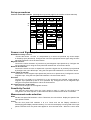
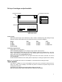
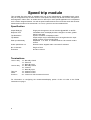
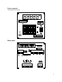
Operating instructions
Multiranger DS Series
and
Microranger DT Series
Panel mounted
Tachometers/ ratemeters
counters/timers
Phone:
Fax:
44 (0) 1204-532544
44 (0) 1204-522285
www.compactinstruments.co.uk
email: [email protected]
Contents
Multiranger Tachometers
DS48 specification
Factory adjustable parameters
Output module Specification
0−10v output
0−20ma output
4−20ma output
Serial Output RS232
Analogue input module
1
2
2
2
2
2
2
3
3
Measuring range and Function select controls & set up
Sensors and Signal inputs
Sensitivity Control
Measurement mode selection
Reset options
Display resolution
Scaling factor setting
Input pulse divider
Pulse Output
Reset
Process time
3
4
4
4
5
5
5
6
6
6
6
Output Modules
Analogue output
Serial output
Analogue ouput setup
6
6
6
6
Input module
7
Speed trip module
Specification
Terminations
Front controls
Rear panel
Preset level setting Procedure
Relay Mode
Count mode
Reset
Inhibit control
Time out / motion stopped
Multiranger numbering system
8
8
8
9
9
10
10
10
10
10
10
11
Microranger Tachometers
DT48 specification
Set up procedures
Sensors and Signal inputs
Measurement mode selection
Reset options
Pulse Output
Reset
Input Divider / Sensor Select options
Microranger numbering system
12
13
14
14
14
15
15
16
16
17
DS
Multiranger
Tachometers
1
Specifications
DS48 specification
Speed modes
Speed range
Accuracy
Resolution
Display update time
0.001 to 99999 rpm (12Khz max using input divider)
- 0.02% of reading ± 1 digit
±1 digit (0.001 RPM below 100RPM)
0.8secs or time between input pulses whichever is longer
0.1 secs if output module fitted
Cycle time
0.01sec to 99,999secs
Count mode
5 digits with overflow to 8 digits (autoranging)
Accumulated time
0.01 - 99999secs
Scaling factor
× or ÷ by 0.001 to 99,999 (operates on all functions)
Power supply options
1) Mains 110−240V AC +10%−15% (ext fuse ceramic 250mA A/S)
2) DC Version 10 to 36v DC
3) 24v AC
Sensor supply
12V DC @50ma, and 5V DC @ 100ma
Enclosure
DIN 48 × 96 × 140mm
Panel cut out 42.5 × 91.5mm
Factory adjustable parameters (To Order)
Internal scaling factor
× or ÷ by 0.001 to 99,999
Update time
0.1 secs to 60secs
Under range speed
3RPM to 0.1RPM
Output module Specification
0−10v output
Update time
Output range
Accuracy
Full scale error
Resolution
Zero offset (max)
Temperature Coefficient
0.1 secs or time between input pulses
0−9.99 Volts
±0.15% of span
±0.15% of span
2.5 mv
25 mV
±30ppm/° C
0−20ma output
Update time
Output range
Accuracy
Resolution
Zero offset (max)
Max load
Temperature Coefficient
0.1 secs or time between input pulses
0−20ma
±0.3% of span
10 microamps
100 microamps
500 Ohms
±100ppm/° C
4−20ma output
Update time
Output range
Accuracy
Resolution
zero offset (max)
Max load
0.1 secs or time between input pulses
4−20ma
±0.3% of span
10 microamps
100 microamps
500 Ohms
Ranges selectable on analogue output
0−999
0−9.99v
0−20ma
0−9990
0−9.99v
0−20ma
0−99900
0−9.99v
0−20ma
0−xxxxx
0−9.99v
0−20ma
2
4−20ma
4−20ma
4−20ma*
4−20ma
*ex−works setting
customer programmable
Serial Output RS232
Update time
Baud Rate
Data Bits
Stop bits
Parity
Output format
End of line character
Connection
0.1 secs or time between input pulses
9600
8
1
none
Displayed value in Ascii characters MSD first including decimal
point.
Carriage return ( 13 decimal, 0D hexadecimal).
RJ11 connector
Analogue input module
Full Scale input
Accuracy
Full scale error
Nonlinearity
Temperature Coefficient
9.99v
±0.15% of span
±0.15% of span
±0.15% of span
±100ppm
Measuring range and Function select controls
To access these remove the front bezel and display filter
Analogue range select
program push button
ON
1
2
1 2 3 4 5 6 7 8 9 10
DIP Switches
Scaling Factor input divider and voltage selection facilities
These are located on the rear panel of the instument
MADE IN UK
9
0
1
9
0
1
9
0
1
9
0
0
9
1
1
8
2 8
2 8
2 8
2 8
2
7
3 7
3 7
3 7
3 7
3
6
5
6
4
MSD
5
4
6
4
5
6
5
6
4
5
1
10
2
3
4
10 10 10
2
3
D.P.
4
1
LSD
SCALING FACTOR
0
INPUT
DIVIDER
SENSITIVITY
MAINS SELECT
120
240
Vac
Vac
220
110
50/60Hz 10Watts max
1
2
3
4
5
+12V
NC
DC Versions
TO BE FUSED EXTERNALLY
L
N
+V
0V
+5V
6
7
8
9
10
11
Time
Prox
OV
Pulse Mag Pu Reset
Output
Note voltage selector switch not fitted on DC versions
3
Set up procedures
Function select DIP switches (see diagram on previous page for the location of these switches)
DIP SWITCHES (FRONT)
1
2
Reset
options
3
4
Measure
mode
5
Scale
set
6
7
8
Display
resolution
9
10
Sensor
Select
off
on
Reset
Tacho/Rate Mult No decimal point
Flash
Count
Hold
Div
NPN
1 decimal point
PNP
Cycle time
2 decimal points
Magnetic
and
Pulse
input
Total
plus
Link 6 &10
3 decimal points
Auto ranging
Remove display bezel & filter to access switches
Sensors and Signal inputs
NPN/PNP Proximity sensors.
Connect the sensor +ve wire to +12v(terminal 4), 0v wire to 0v (terminal 10), sensor output
to Proximity input (terminal 8). Configure the unit to the appropriate sensor type using the front
panel DIP switches 9 & 10 as shown above.
Magnetic sensors .
Connect the sensor between 0v( terminal 10) and Magnetic input (terminal 9). Configure the
unit to magnetic input using the front panel DIP switches 9 & 10 as shown above.
Namur 2-wire sensors
Connect the sensor 0v wire to 0v(terminal 10) and the signal wire to proximity input (terminal
8).Configure the unit to NPN input using the front panel DIP switches 9 & 10 as shown above.
Pulse inputs (2−30v DC)
Connect the +ve to magnetic input (terminal 9) and 0v to 0v (terminal 10). Configure the unit to
magnetic input using the front panel DIP switches 9 & 10 as shown above.
Encoders
Connect the +ve supply to 5v (terminal 5) or 12v (terminal 4) as required, output signal to
magnetic input (terminal 9) and 0v to 0v (terminal 10). Configure the unit to magnetic input
using the front panel DIP switches 9 & 10 as shown above.
AC signal sources ( 2−30v Peak)
Connect and configure as for magnetic sensors
Sensitivity Control
This sets the level above which the input needs to reach in order for the signal to be
recognised. The noise rejection of the instrument also increases as this level is increased.
Measurement mode selection
RPM
Set the front panel DIP switches 3 & 4 to Tacho/rate, the unit will then display the speed of the
input pulses in RPM.
Count
Set the front panel DIP switches 3 & 4 to Count and set the Display resolution to
Autoranging(see Display resolution below). The unit will now display a running total of the input
pulses received since the power was applied or since the last reset. When the count value
4
exceeds 99,999 counts the unit will auto-range and count in 10’s . The decimal point will move
to indicate the position of the thousands ( i.e. it can be read as the comma that separates
thousands from the hundreds e.g. 264.12 = a count of 264,120). If the count again exceeds
999.99 it will again auto-range and count in 100’s. The maximum count is 99,999,999.
Accumulated time / Count duration
If during a count session “time” ( rear terminal 6) is connected to 0v (terminal 10) the unit will
display the time elapsed since the count began. On removing this connection the count will
again be displayed.
Cycle Time/ Time interval
Set the front DIP switches 3&4 to Cycle time and the display resolution to Auto ranging. The
unit will now display the time between successive input pulses to a maximum resolution of
0.01 seconds. If the time exceeds 99.990 Secs the unit will auto-range and continue to display
the time up to 999.99 secs. It will again autorange and display time up to 9999.9 secs but to a
resolution of 0.1 seconds. At times greater than 9,999.9 seconds the unit will again auto-range
enabling a maximum count value of 99,999 seconds to a resolution of 1 second. When used in
conjunction with the scaling factor this mode can be used to display long process times but
with a fast update ( see Process time page 6)
Display resolution (rpm modes only)
The resolution of the display can be set to either a fixed resolution of 0,1,2 or 3 decimal places
or to be fully autoranging in which case the maximum number of decimal places possible at
the current speed will be displayed. To select auto range mode set DIP switch 6 to on, in this
case switches 7&8 will have no effect. To select a fixed number of decimal places set DIP
switch 6 to off and select the number of decimal places required as per the above diagram.
Note that when in fixed resolution mode if a resolution is chosen that is too great to fit the
whole value in the 5 digit display the higher digits will be lost but the overall measurement
resolution is not changed so the least significant digits will not be displayed to the full accuracy
of the unit.
Reset options
These two DIP switches determine the operation of the unit in under-range and over- range
conditions the alternatives are:1 Reset to zero if no pulses have been received for 20 seconds ( i.e. if the input speed is
less than 3 rpm) DIP switch 1 should be set to on. If this is set then it overrides the action of
DIP switch 2
2 Continue to measure below 3 RPM. DIP switches 1&2 off. In this case the unit will continue
to measure speeds down to 0.001rpm. Note in this mode if the apparatus being measured
stops then the unit will never go to zero but will continue to display the last reading.
3 Flash Display on under/over-range conditions DIP switch 2 on. In this case the display
will flash when an input pulse has not be received for 20 seconds and the display holds the
last reading until another pulse is received. It will also flash the display if the displayed
value is greater than 99,999 or if displaying a fixed number of decimal places the value is
larger than can be displayed with those number of decimal places.
Scaling factor
This function can be applied to all measurement modes and is set using the 5 rotary BCD
switches labelled scaling factor on the rear panel and the upper rear slide switch. The scaling
factor can be either a multiplication factor or a division factor.
To set the Scaling factor first determine whether the value should be divided or multiplied by
the factor and set the Front DIP switch 5 accordingly. Enter the scaling factor including any
decimal places required into the 5 scaling factor switches. If the factor contains decimal
places then set the rear upper slide switch to the number of decimal places required. Eg. for a
scaling factor of 24.86 set the switches as shown
9
0
1
8
9
0
1
7
3 7
6
5
MSD
4
9
0
1
2 8
2 8
3 7
6
5
4
9
0
5
4
SCALING FACTOR
0
1
2 8
3 7
6
9
1
2 8
3 7
6
5
4
0
1
2
3
D.P.
2
3
6
5
4
LSD
5
The scaling factor resolution and the display resolution are completely independent of each
other however the measurement resolution can not be increased by the scaling factor e.g. if
the unit is in count mode and the scaling factor is set to multiply by 43 the for each count input
the display will increment in steps of 43.
The scaling function is purely a mathematical calculation on the measured value and hence
has no adverse effect on update time etc.
Input pulse divider
This is the lower slide switch on the rear panel. It enables the input pulse rate to be divided by
1, 10, 102(100), 103(1,000) and 104(10,000). This can be used to measure pulse rates higher
than the normal maximum input rate of 99,999rpm up to a maximum of 12Khz ( 5v square
wave 1:1 mark space ratio). It can also be used at slower speeds to average or smooth erratic
readings. If the divided input period is Greater than 0.8 seconds then the update time will
become the input period thus enabling the update and hence the averaging effect to be
increased.
NOTE when the reset options (see above) are enabled these refer to the pulse rate after the
input divider.
Pulse Output
A 5v TTL compatible output is available on terminal 7. This output is at the same rate as the
incoming pulse rate no scaling is applied to it. It can be used to drive addition instruments that
require a 5v pulse input. The maximum loading on this signal is 1K pull up to 5v or 100k
pulldown to 0v.
Reset
A reset capability is available via terminal 11 on the rear panel. The unit can be reset
momentarily connecting this terminal to 0v (terminal 10) . When the reset is connected to 0v
the unit will stop and the display will continue to display the last reading. When Ov is removed
from the reset. The Unit is only then reset internally with the measurement starting again from
zero.
Process time
Long process times such as those of baking ovens can be measured and controlled with a fast
update time by using the Time interval mode in conjunction with the scaling factor. This can be
achieved by monitoring the speed of the conveyors drive motor. These pulses can be reduced
in frequency by using the input divider until the measured value is of sufficient resolution. The
displayed value can then be scaled so that the display indicates the actual process time. Using
this method it is possible to measure process times of long durations (several minutes or even
hours) and yet have an update of only a few seconds.
Output Modules
Analogue
These are optional factory fitted modules that enable the measured value to be output in
various preselected formats for further processing, recording or to be used for control
purposes. The voltage and current outputs are available on rear terminal 6. The current/
voltage outputs have three fixed ranges and one customer programmable mode. In the fixed
ranges the maximum output voltage/current corresponds to 999 in either the left hand three
digits of the display, the middle three digits or the right hand three digits. In each case the
other digits in the display have no effect on the output. The output is updated at the same rate
as the display and between updates the output remains constant.
If one of these is fitted then the Display update time is set at 0.1 seconds.
Serial
The RS232 output is via a RJ11 connector situated on the side of the instrument. This output
continually transmits as ASCII characters the value in the display.
The connections to RJ11 connector are pin 2 = Transmitted data, pin 5 = 0volts
Only one of the voltage/current types may be fitted at once, the RS232 out may be fitted in
conjunction with one of these or on its own.
6
Set up of analogue output module
program push button
Analogue range select
ON
ANALOGUE RANGE SELECTION
1
FRONT VIEW
1
2
2
RANGE
0 - 999
0 - 9990
0 - 99900
customer program
REAR VIEW
1 2 3
4 5 6 7 8 9 10 11
ANALOGUE OUTPUT
Preset ranges
Select the speed range to be measured (0−999, 0−9990, 0−99,900) using the analogue range
selection switches found behind the front panel as shown in the above diagram.
Range
0−999
0−9990
0−99900
works setting
DA1
0−9.99v
0−9.99v
0−9.99v
DA2
0−20ma
0−20ma
0−20ma
DA3
4−20ma
4−20ma
4−20ma* *ex-
Customer program mode
Apply power to the instrument
Select customer program on the analogue range selection DIP switches
Enter the maximum speed that the full scale analogue output will correspond to, via the 5
rotary BCD switches on the back panel any decimal place required can be set using the
upper slide switch (see scaling factor page 5)
Press the program push button once, the green LED next to the switch will flash. The unit is
now programmed
Set the rear BCD switches to the scaling factor required (if no scaling is required set to 00001)
Note: The accumulated time mode is not available on units fitted with an analogue output.
Input module
This allows a voltage of 0−10v to be applied to the input of the unit which will then show a
value of 0−9,999 on the display. This value may then be scaled as required using the rear
scaling factor switches.
Connect the Ov to terminal 10 and the positive input to terminal 6
Note The input divider switch must be set to divide by 10 position
7
Speed trip module
This versatile Set point alarm is available with one or two independently presettable levels, which
may be configured to trip on either under or over speed, the relays may be set to either energised or
de-energised in either case. An inhibit timer for start up on under speed applications is incorporated
as is a motion stopped detector. As well as speed measurements the unit will also work with all other
measurement modes of the tachometer i.e. Count, cycle time and accumulated time.
Specification
Output Relay(s)
Reponse Time
Under speed time out
Single pole changeover 2A non-inductive @240VAC or 30VDC
Immediate when the displayed value changes to a value greater
than the set value
Equal to resolution of displayed value
Output relays may be individually set to energise when the input
speed is under or over the set speed
Adjustable 1—9 Secs. or customer defined via external contact
closure
Detects motion stopped within 3 seconds if activated
No of channels
Enclosure
Single or Dual
96 x96 x 136 mm
Trip Resolution
Trip Modes
Start up inhibit delay
Terminations
Level 1 relay
Level 2 relay
Time out
Inhibit
Common
12 - Normally closed
13 - Common
14 - Normally open
15 - Normally closed
16 - common
17 - Normally open
18 - external control
19 - external control
20 - common 0 volts for external control
For information on configuring the measurement/display portion of this unit refer to the DS48
instructions on page 1
8
Front controls
Located behind front panel.
S1
H
O
L
D
F
L
A
S
H
T
I
N
T
C
O
U
N
T
A
U
T
O
x
.
.
1 2 N
D D P
P P N
DP SELECT
DP1 DP2
0
0
1
0
0
1
1
1
P
N
P
- S4
SELECTED
NONE
ONE
TWO
THREE
LEVEL 1
0
S2
MODE
DP1
DP2
4
5
6
DP2
DP1
MODE
S3
INHIBIT
DELAY
SECS
1
SW1
2
3
S4
LEVEL 2
5
4
6
1
9
7
3
S5
8
2
0
MODE
SW4/1+6
DISPLAY BELOW LEVEL
0
1
RELAY DE-ENERGISED
RELAY ENERGISED
0 = EXT. CONTROL
Rear panel
MADE IN UK
9
0
1
9
0
1
9
0
1
9
0
0
9
1
1
8
2
8
2
8
2
8
2
8
2
7
3
7
3
7
3
7
3
7
3
6
6
4
5
4
6
4
6
5
5
MSD
6
4
0
1
10
10
2
D.P.
4
5
5
2
1
LSD
SCALING FACTOR
3
3
10
4
10
INPUT
DIVIDER
SENSITIVITY
MAINS SELECT
1
2
3
4
120
240
Vac
110
220
Vac
5
6
7
8
9
10
11
50/60Hz 10Watts max
NC
L
+12V
N
TO BE FUSED
+12V
EXTERNALLY
0v (DC versions)
LEVEL 1
LEVEL 2
N/C
COM
N/0
N/C
COM
N/0
12
13
14
15
16
17
+5V
Time
Prox
OV
Reset
Pulse Mag Pu
T
I
I
N
M
H
E
I
O
B
C
U
I
O
T
T
M
19
20
18
9
Preset level setting Procedure
Enter the required value on the thumbwheel switches including any decimal places (e.g If the
unit is required to trip at 231.32 RPM enter 23132)
Select the number of decimal places required using the dip switches S4 (SW1&2 refer to level
1 setting, SW4&5 refer to Level 2 settings.
Decimal Places
None
DP1
0
DP2
0
One
1
0
Two
Three
0
1
1
1
E.G for the value 321.32 set the switchs to:-0
1
MODE
DP1
DP2
Note: Always set the resolution of the thumbwheel setting to be the same as that of the
Display. (The unit will still work if these do not match but there will be a loss of resolution)
Relay Mode
(S4 DIP switches SW1 /SW4)
These switches determine whether the output relay is energised or de-energised when the
display is above or below the set point.
Count mode
If the display unit is set to Count mode then the unit will act as a predetermined counter. The
unit will trip as soon as the displayed count exceeds the selected value. NOTE;- there is
no provision for auto resetting, the unit will continue counting after the set value has been
reached.
Reset
A reset capability is available via terminal 11 on the rear panel. The unit can be reset by
momentarily connecting this terminal to 0v (terminal 8) . When the reset is connected to 0v
the unit will stop , the display will continue to display the last reading and the relays will
remain in the same state. When Ov is removed from the reset. The Unit is only then reset
internally with the measurement starting again from zero.
Inhibit control
This is normally used when the unit is being used to detect under speed. It allows the unit
being monitored to reach operating speed without triggering an under speed alarm.
Internal control this is set using the rotary switch S5 on the front panel. This can be set to
select start up inhibit times from 1 to 9 seconds in 1 second increments
External control -to activate this mode S5 must be set to zero. The unit will then wait for a
momentary contact closure across terminal 19 & 20. Note unless external control is
required do not set S5 to zero.
Time out / motion stopped
Normally the unit will not recognise that the input pulses have stopped until the Display drops
to zero, this in turn depends on the reset options chosen for the display unit (with the
normal 3 RPM limit this would be 20 seconds)
In order to rapidly detect that a machine has stopped (e.g. in cases of mechanical failure) the
unit can be set to time out after 3 seconds by connecting Timeout (terminal 18) to Common
(terminal 20)
10
Multiranger numbering system
DS
CASE SIZE
48 = 48x96
96 = 96x96
72 = 72x72
BT= Bench
PT = Portable
SUPPLY
1 = 240/110 VAC
2 = 10 -36VDC
3 = 24VAC
ANALOGUE OPTIONS
0 = None
1 = 0-10 VDC
2 = 0-20 ma
3 = 4-20 ma
4 = 0-10 VDC input
XX
X
X
X
X
X
/XXX
SPECIAL
RS232 OUTPUT
0 = NONE
1 = FITTED
TRIP OUTPUT
0 = NONE
1 = 1 Level
2 = 2 Level
Note must be in
96 x96 CASE
SEALS
0 = None
1 = IP55 Fitted
11
DT
Microranger
Tachometers
12
The Microranger series of DIN Digital tachometers are versatile instruments which can be used to
measure rotational speed, cycle time, count and accumulated time. With the addition of the Input
divider/ sensor select module the measured speed may be scaled to display the rate in
engineering units and a wider range of sensor types can be used.
Specifications
DT48 specification
Speed modes
Speed range
accuracy
Resolution
Display update time
0.001 to 99999 RPM (12,000,000 using input divider)
- 0.02% of reading ± 1 digit
±1 digit (0.001 RPM below 100RPM)
0.8 secs or time between input pulses whichever is longer
Cycle time
Accumulated time
Count mode
Power supply options
0.01 sec to 99,999 secs
0.01 sec to 99,999 secs
5 digits with overflow to 8 digits (autoranging)
1) Mains 110−240V AC +10%−15% (ext fuse ceramic 250mA A/S)
2) DC Version 12V DC
12V DC @50ma, and 5V DC @ 100ma
DIN 48 × 96 × 115mm (123mm including connectors)
Panel cut out 42.5 × 91.5mm
Sensor supply
Enclosure size
Scaling factors
×1 (standard)
×10, ×100
3 decade ÷1—999 (only available when input divider / sensor
select option is fitted)
Division factor
REAR VIEW
SENSOR
1
2
SELECTOR
INPUT PULSE DIVIDER
3
MSD
4
9
0
LSD
0
9
1
9
1
8
2
8
2
8
7
3
7
3
7
6
5
4
6
5
4
0
1
2
3
6
5
4
MAINS SELECT
120
240
1
2
3
NC
NC
L
N
+12v
0v
DC versions
4
5
6
7
+10V
+5v
+0V
8
9 10 11 12
SIG
OUT
TIME
RESET
0V
Rear panel
Note sensor select switches and input pulse divider are only available when input divider/ sensor
select option is fitted
13
Sensitivity control
Input divider / sensor select
options only
1 2 3 4 5 6 7 8 9 10
DIP Switches
DIP switches
( located behind the front display filter)
Set up procedures
Function select DIP switches (see diagram above for the location of these switches)
DIP SWITCHES (FRONT)
1
2
3
Measure Not
used
mode
4
5
Fixed
multiplier
6
7
8
Display
resolution
9
10
Reset
options
Off
On
Tacho/Rate Off
rpm x 1
No decimal point
Reset
rpm x 10
1 decimal point
Flash
Cycle time
rpm x 100 2 decimal points
Hold
Total
plus
Link 9 &11
3 decimal points
Count
Auto ranging
Factory default settings
Sensors and Signal inputs
NPN Proximity sensors.
Connect the sensor +ve wire to +10v (terminal 6), 0v wire to 0v (terminal 7), sensor output to
Signal input (terminal 8).
Namur 2-wire sensors
Connect the sensor 0v wire to 0v(terminal 7) and the signal wire to Signal input (terminal 8).
Measurement mode selection
RPM
Set the front panel DIP switches 1 & 2 to Tacho/rate, the unit will then display the speed of the
input pulses in RPM.
14
Count
Set the front panel DIP switches 1 & 2 to Count and set the Display resolution to Autoranging
(see Display resolution below). The unit will now display a running total of the input pulses
received since the power was applied or since the last reset. When the count value exceeds
99,999 counts the unit will auto-range and count in 10’s. The decimal point will move to
indicate the position of the thousands (i.e. it can be read as the comma that separates
thousands from the hundreds in a normal written number,e.g. 345,19 = a count of 345,190). If
the count again exceeds 999.99 it will again auto- range and count in 100’s. The maximum
count is 99,999,999.
Accumulated time
If during a count session “time” ( rear terminal 9) is connected to 0v (terminal 11) the unit will
display the time elapsed since the count began. On removing this connection the count will
again be displayed.
Cycle Time
Set the front DIP switches 1&2 to Cycle time and the display resolution to Auto ranging. The
unit will now display the time between successive input pulses to a maximum resolution of
0.01 seconds. If the time exceeds 99.990 Secs the unit will auto-range and continue to display
the time up to 999.99 secs It will again autorange and display time up to 9999.9 secs but to a
resolution of 0.1 seconds. At times greater than 9,999.9 seconds the unit will again auto-range
enabling a maximum count value of 99,999 seconds to a resolution of 1 second.
Display resolution (rpm modes only)
The resolution of the display can be set to either a fixed resolution of 0,1,2 or 3 decimal places
or to be fully autoranging in which case the maximum number of decimal places possible at
the current speed will be displayed. To select auto range mode set DIP switch 6 to on, in this
case switches 7&8 will have no effect. To select a fixed number of decimal places set DIP
switch 6 to off and select the number of decimal places required as per the above diagram.
Note that when in fixed resolution mode if a resolution is chosen that is too great to fit the
whole value in the 5 digit display the higher digits will be lost but the overall measurement
resolution is not changed so the least significant digits will not be displayed to the full accuracy
of the unit.
Scaling
Three fixed ratios can be applied to the measured value ×1, ×10, ×100 (rpm modes only)
these are selected using DIP switches 4&5 as shown in the above diagram. This feature is
normally used in conjunction with the input divider option ( see below)
Reset options
The two DIP switches 9&10 determine the operation of the unit in under-range and over- range
conditions the alternatives are:Reset to zero if no pulses have been received for 20 seconds ( i.e. if the input speed is
less than 3 rpm) DIP switch 9 should be set to on. If this is set then it overrides the action of
DIP switch 10 (over-range enable)
Continue to measure below 3 RPM. DIP switches 9&10 off. In this case the unit will continue
to measure speeds down to 0.001 rpm. Note in this mode if the apparatus being measured
stops then the unit will never go to zero but will continue to display the last reading.
Flash Display on under/over-range conditions DIP switch 10 on. In this case the display will
flash when an input pulse has not be received for 20 seconds and the display holds the last
reading until another pulse is received. It will also flash the display if the displayed value is
greater than 99,999 or if displaying a fixed number of decimal places the value is larger than
can be displayed with those number of decimal places.
Pulse Output
A 5v TTL compatible output is available on terminal 10. This output is at the same rate as the
incoming pulse rate no scaling is applied to it. It can be used to drive addition instruments that
require a 5v pulse input. The maximum loading on this signal is 1K pull up to 5v or 100k
pulldown to 0v.
15
Reset
A reset capability is available via terminal 12 on the rear panel. The unit can be reset by
momentarily connecting this terminal to 0v (terminal 11) . When the reset is connected to 0v
the unit will stop and the display will continue to display the last reading. When Ov is removed
from the reset the Unit will then reset internally with the measurement starting again from zero
Input Divider / Sensor Select options
If this option is fitted the following extra features are available
Sensor selection
SENSOR
NPN (PROXIMITY)
SWITCHES
Factory Default setting
PNP (PROXIMITY)
OPTICAL
ENCODER
MAGNETIC
2-WIRE NAMUR
NPN/PNP Proximity sensors.
Connect the sensor +ve wire to +10v (terminal 6), 0v wire to 0v (terminal 7), sensor output to
signal input (terminal 8). Configure the unit to the appropriate sensor type using the rear panel
DIP switches 1—4 as shown above.
Magnetic sensors .
Connect the sensor between 0v( terminal 7) and Signal input (terminal 8). Configure the unit to
magnetic input using the rear panel DIP switches 1—4 as shown above.
Namur 2-wire sensors
Connect the sensor 0v wire to 0v(terminal 7) and the signal wire to signal input (terminal
8).Configure the unit to NPN input using the rear panel DIP switches 1—4 as shown above.
Pulse inputs (2−30v DC)
Connect the +ve to magnetic input (terminal 8) and 0v to 0v (terminal 7). Configure the unit to
magnetic input using the rear panel DIP switches 1—4 as shown above.
Encoders
Connect the +ve supply to 5v (terminal 5) or 12v (terminal 6) as required, output signal to
Sensor input (terminal 8) and 0v to 0v (terminal 7). Configure the unit to magnetic input using
the rear panel DIP switches 1—4 as shown above.
AC signal sources ( 2−30v Peak)
Connect and configure as for magnetic sensors
Sensitivity Control
This is situated behind the front panel sets the level above which the input needs to reach in
order for the signal to be recognised. The noise rejection of the instrument also increases as
this level is increased.
Input Scaling
A scaling factor may be applied to the measured speed in two ways
1. The input signal may be divided by a 1—999 using the 3 rotary switches on the rear panel.
This may be used on all measurement modes. NOTE as this divides the input signal before
it is applied to the measurement system tthere could be a large increase in update time at
slow input rates with large division factors.
2 Multiplication factors ×1,×10,×100 can be selected using the front DIP switches 4&5 and
can be used in conjunction with the rear division factor to give a range of scaling factors
from ×100 to ÷ 999. This is can only be used on rpm modes.
3 Input pulse divider RPM - where more than one pulse per revolution is being used via a
sensor the input divider should be set to the number of pulses per revolution.
16
Microranger numbering system
DT
CASE STYLE
XX
X
X
X
/XXX
SPECIAL
48=48×96 PANEL MOUNTED
SUPPLY
1= 240/110 VAC
2=12VDC
SEALS
0= NONE
1= IP55 FITTED
INPUT DIVIDER/SENSOR
SELECT OPTION
0= NONE
1= FITTED
17
©Compact Instruments Ltd February 2003
Document No: 13989/4.3
18