1
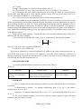
Scientific Production Company “Doza” X-RAY DOSIMETER DKR-04M User manual FVKM.412113.036RE Cont ent 1 Description and operation of the product ……………………….…………. 1.1 Product functionality …………………………………….………… 1.2 Technical characteristics ……………………………..……………. 1.3 Configuration …………………...…………………..……………… 1.4 Design and operation …………………...…………..……………… 1.5 Marking and sealing ………………………………...…………..…. 1.6 Packing ……………………………………………...……………... 2 Intended use …………………………………………..………………….… 2.1 Operational limitations ………………………..…………………… 2.2 Preparation of the product for use ..…………...…………………… 2.2.1 Turning on/off ……….….….……………………………………. 2.3 Use of a product …….….….………………….……………………. 2.3.1 Selection of operation mode and performing measurements ….… 2.3.2 Reset of total dose …….…….…….….….…………………….… 2.3.3 Review and setting of thresholds ………………………………… 2.3.4 Battery replacement ….….……………………………………….. 2.4 Adjustment ……………………………….………………...……… 3 Maintenance …………………………………………...…………………… 3.1 General notes ……………………………………….……………… 3.2 Safety precautions ……………………………………………….… 4 Calibration routine ………………………….……………….…...………… 4.1 General requirements …………………………................................ 4.2 Calibration operations ………………………………...………....… 4.3 Calibration equipment ………………………………...………....… 4.4 Safety precautions ……………………………………………….… 4.5 Conditions …….…………..………………………….………….… 4.6 Procedure …………………….……………...…….……………….. 5 Routine repairs ……………………………………………………………... 6 Storage …………………………………………………………...………… 7 Transportation …………………………………………………….……….. 8 Utilization …………………………………………………….……………. FVKM.412113.036RE 2 3 3 3 4 4 4 4 5 5 5 5 5 5 6 6 6 7 7 7 7 7 7 7 8 8 8 8 9 9 10 10 This User Manual contains information on design, principle of operation, characteristics of the product and instructions essential for correct and safe use of this product (intended use, maintenance, servicing, storage and transportation), as well as information regarding the utilization of the product. 1 DESCRIPTION AND OPERATION OF THE PRODUCT 1.1 Product functionality Dosimeter of X-ray radiation DKR-04M FVKM.412113.036 (hereinafter - dosimeter) is intended for measurement of personal dose equivalent (PDE) of X-ray radiation, personal dose equivalent rate (PDER) of X-ray radiation and for signalling when the PDE or PDER threshold is exceeded. The dosimeter is used for monitoring of personal doses of personnel working with X-ray sources. 1.2 Technical characteristics 1.2.1 Energy range of measured X-ray radiation …………………...…………… 15 to 150 keV. 1.2.2 Measurement range of PDE ……………….……………………………… 1 μSv to 10 Sv. 1.2.3 Measurement range of PDER ……………….…………………… 1 μSv h-1 to 50 mSv h-1. 1.2.4 Limits of the permissible basic relative measurement error: - PDE ………………………………….……...……….………..……………… ±[15+5/ Н ]; ], - PDER …………………………..…………………..……..………………… ±[15+30/ Н , H are dimensionless units, numerically equal to measured values of measured PDE or where PDER in μSv and μSv·h-1, accordingly. 1.2.5 Energy dependence of sensitivity relative to sensitivity to radiation with effective energy 100 keV ……………………..……..…….……….………………….… ±35 %. 1.2.6 Anisotropy of sensitivity at energy 30 keV for angles of incident radiation from 0 to ±60° relative to the axis perpendicular to the back plane of the dosimeter ………..… 35 %. 1.2.7 Warm-up time ………………………..……..……………………………….…… 1 min. 1.2.8 Continuous operation without replacement of battery …………………… 2000 hours, when working with an audio signal in a normal mode – not more than one beep per minute at the end of measurement intervals. 1.2.9 Instability of readings during 8 hours of continuous operation relative to average value of readings for this period of time ……………………….…………………………….….………… ±5 %. 1.2.10 Thresholds for audible and visual alarms are preset by the manufacturer: PDE – 16 mSv and PDER 8 μSv h-1. The user can change these thresholds by selecting desired values from 32 values for PDE and 16 values for PDER, which are stored in the dosimeter’s memory. 1.2.11 The refreshing period of PDER readings on the LCD automatically increases as the PDER decrease from 1 second (at PDER above 2 mSv h-1) to 255 seconds (at PDER equal to or below 7.5 μSv h-1). 1.2.12 Power supply of the dosimeter is provided from one disk lithium battery of CR 2450 type with voltage 3.2 V. 1.2.13 Operating conditions: - operating temperature range …...….….…….….….…….…….......….. minus 10 to + 40 C; - maximum limit of relative humidity ………….….….……….….…………. 80 % at +25 C; - atmospheric pressure …………………………………………….…….… 84.0 to 106.7 kPa; - content of the corrosive agents in the ambient air corresponds to the values in Table 1.1. FVKM.412113.036RE 3 Table 1.1 Type of atmosphere Designation Designation I Relatively clean II Industrial Content of the corrosive agents Sulfur dioxide gas not more than 20 mg/(m2·day) (not more than 0.025 mg/m3); Chlorides not more than 0.3 mg/(m2·day) Sulfur dioxide gas not more than 20 to 250 mg/(m2 ·day) (not more than 0.025 to 0.31 mg/m3); Chlorides not more than 0.3 mg/(m2·day) 1.2.14 Limits of complementary measurement error due to deviation of temperature from normal value, per each 10 °C ………………………………….…………………………………±10 %. 1.2.15 In the PDE and PDER measurement mode the dosimeter withstands short, with duration up to 5 minutes, irradiation at dose rate 20 Sv·h-1. 1.2.16 Weight of the dosimeter, including battery ……………………… not more than 0.04 kg. 1.2.17 Overall dimensions of the dosimeter with clip ………...… not more than 56×34×18 mm. 1.2.18 Mean time to failure …………….……….………….…..….…. not less than 4500 hours. 1.2.19 Mean life time ………………………….….….………….……..…. not less than 7 years. 1.3 Configuration All parts of the dosimeter are placed in a compact case of high-impact plastic. A clip is provided for fastening to the clothes. 1.4 Design and operation 1.4.1 A silicon detector is used as a detector of X-ray radiation; the detector is equipped with energy compensation filter. The detector converts flux of ionizing radiation into a sequence of electrical pulses. 1.4.2 During operation the dosimeter is controlled by a microprocessor, which performs the following functions: conversion of a sequence of pulses into the PDE and PDER values, self-testing, accumulation and storage of total PDE, control of the battery voltage, etc. The measurement result and corresponding measurement unit are shown on the LCD with three digits. 1.5 Marking and sealing 1.5.1 The following information is presented on the dosimeter’s case: - trademark and name of the manufacturer (supplier); - reference designation of the dosimeter; - works number of a dosimeter according to the manufacturer's system of numeration; - made in Russia. 1.5.2 Location and method of marking of the dosimeter correspond to the design documentation. 1.6 Packing 1.6.1 The dosimeter is packed into a carton which ensures protection against ingress of atmospheric precipitations and aerosols, splashes of water, dust, sand, solar ultra-violet radiation and also limits the ingress of water vapour and gases. FVKM.412113.036RE 4 2 INTENDED USE 2.1 Operational limitations 2.1.1 When the supply voltage falls below 2.8 V the flashing symbol of a battery (“low battery”) appears on the LCD of the dosimeter and every 30 minutes an audible signal with duration of 1 second is generated. After appearance of this flashing symbol replace the battery in accordance with 2.3.4. If operation of the dosimeter is continued without battery replacement, then after the voltage falls below 2.7 V the dosimeter beeps and turns off automatically; after that the LCD shows a flashing battery symbol only. In this case accumulated information is stored in non-volatile memory. Turning the dosimeter on is only possible after replacing the battery. When using the dosimeter under conditions of low temperature close to the limit of minus 10°C, the “low battery” symbol may appear on the LCD when battery is charged. In this case, the dosimeter will automatically turn off at least after several days of continuous operation. 2.1.2 Protected the dosimeter from mechanical damage: falls, shocks, compression. 2.1.3 Protected the dosimeter from direct exposure to water. In rainy environment put the dosimeter in a plastic bag. Remove contamination using a swab wetted with detergent solution or alcohol. 2.1.4 During operation the dosimeter should be located at least 10 cm from cellular phones when they are turned on or from any other source of electromagnetic radiation of similar emission power. If this requirement is not complied with then the dosimeter can respond to a source of electromagnetic emission as if it is a source of ionizing (X-ray or gamma) radiation. 2.2 Preparation of the product for use 2.2.1 Turning on/off The dosimeter is controlled by means of a single control button. Turning the dosimeter on is performed by a sliding push on the control button upward. After that, the dosimeter will perform self-test and switch to the measurement mode with indication of the current PDE. If during operation a fault of electric circuit happens the LCD will show symbols “E-1”. If the battery voltage falls below 2.7 V the dosimeter will turn off in compliance with 2.1.1. In the process of self-testing of the dosimeter generates audible and visible (red LED) signals, at the same time all segments of the LCD and special symbols are lit for a while; that allows the user to evaluate the operability of the LCD, audible and visible signals. To turn off the dosimeter press the control button. Keep the button pressed until “OFF” is displayed, then release the button and press again no later than 5. If the second pressing is not done, the dosimeter will automatically return to the measurement mode. When the dosimeter is off, the “OFF” periodically appears on the LCD to confirm that the battery is charged and the dosimeter is ready for switching to the measurement mode. If in the off state the battery voltage is below 2.8 V than the “battery low” symbol will be shown on the LCD instead of “OFF”. If this is the case replace the battery before switching the dosimeter on. The current consumed by the dosimeter in off state does not exceed the self-discharge current of batteries used. 2.3 Use of a product 2.3.1 Selection of operation mode and performing measurements Dosimeter can operate in two modes when it indicates: - personal dose equivalent rate of X-ray radiation; - personal dose equivalent of X-ray radiation. FVKM.412113.036RE 5 Switching between modes, as well as performing other operations while using dosimeter is done by pressing the control button. Execution of command is confirmed by a beep. Flashing radiation hazard symbol indicates that the measurement process is in progress. WARNING! DURING THE MEASUREMENT THE DOSIMETER SHALL BE PLACED INTO THE BREAST POCKET OF CLOTHS. THE LCD SHALL FACE THE BODY! To recall the value of total dose accumulated during the full operation time, or since the last reset of dose, if any, press the control button in the PDER measurement mode and hold it until the second beep is heard. After second beep release the button. Values of thresholds for PDE and PDER will be displayed one after another and then - the value of total PDE. After that the dosimeter will automatically return to the PDER display mode. 2.3.2 Reset of total dose To display the value of total dose, press and hold the control button until the periodic short beeps are heard and then release the button. The indicator will display a zero value of the total dose. To confirm your decision to reset total dose press and release the control button. The value of the total dose will be reset and the dosimeter will turn off. If within 3 seconds the button is not pressed in confirmation, then the dosimeter will turn off without resetting the total dose. 2.3.3 Review and setting of thresholds Thresholds for alarm signals for PDE and PDER preset by the manufacturer according to 1.2.10 can be changed by the user by means of control button. The user can select any value for the thresholds from 16 values for PDER and 32 values for PDE, which are stored in the dosimeter’s memory. The procedure for changing the audible alarm threshold is as follows: - turn the dosimeter on by short press on the control button; - not later than during the first second after the dosimeter is turned on, press and hold the control button, after that the thresholds for PDE and PDER will be displayed successively; - release the button when the threshold to be corrected is displayed; - successively pressing the control button select the desired threshold value; - if the control button is not pressed in 3 seconds, then the dosimeter will either proceed to setting the next threshold, or begin the process of measurement. Remember that measurement of PDE and PDER is always performed simultaneously, at that in case when the PDE threshold is exceeded when the PDER is displayed the “Sv” in designation of the measurement unit will flash, and when the PDER threshold is exceeded when the PDE is displayed the “/h” in the measurement unit will flash. When the measured PDER value exceeds 50 mSv·h-1, a continuous alarm is triggered notifying the user that the PDER value is outside the measurement range. When the measured PDE value exceeds 10 Sv, a continuous alarm is triggered notifying the user that the PDE value is outside the measurement range. 2.3.4 Battery replacement When the battery voltage falls to 2.8V a 1 second warning beep will be heard. The beep will be repeated every 30 minutes of operation and the “low battery” symbol will appear on the LCD. The dosimeter can operate several days in this state but then can suddenly turn off when the battery is fully discharged. Therefore when the “low battery” symbol appears it is necessary to replace the battery. To replace the battery turn the dosimeter off, unscrew the fixing screw and remove the cover. To remove the cover pull the lug of the cover out of the slot in the dosimeter’s case; do not apply excess force that could damage the cover or the case. The lid is removed by sliding along dosimeter’s case. Using a rod of non-conductive material (a pencil, a pen, etc.), remove the battery and replace it with the new one in correspondence with polarity. Place the cover on the case of the dosimeter and fix it with screw. Turn the dosimeter on to check its operability. FVKM.412113.036RE 6 2.4 Adjustment 2.4.1 Correction of the sensitivity coefficient. When the dosimeter’s readings overstate the measured values the sensitivity coefficient shall be increased proportionally, when readings understate the measured values - the sensitivity shall be proportionally decreased. The procedure for correction of the sensitivity coefficient: - turn the dosimeter on by short press on the control button; - not later than during the first second after the dosimeter is turned on, press and hold the control button, after that the thresholds for PDE and PDER will be displayed successively then within 5 seconds all segments and symbols of the LCD will be lit, then the sensitivity coefficient and linearization coefficient will be displayed successively; - release the button when the sensitivity coefficient is displayed; - successively pressing the control button select the desired value of sensitivity coefficient; - if the control button is not pressed in 3 seconds, then the dosimeter will proceed to setting the linearization coefficient and then begin the process of measurement. WARNING! THE SENSITIVITY COEFFICIENT SHALL BE CORRECTED ONLY DURING CALIBRATION. WARNING! THE LINEARIZATION COEFFICIENT IS SET BY THE MANUFACTURER; IT SHOULD NOT BE CORRECTED DURING CALIBRATION. DO NOT CHANGE THE LINEARIZATION COEFFICIENT AS IT WILL UNBALANCE THE LINEARITY OF THE DOSIMETER’S READINS. 3 MAINTENANCE 3.1 General notes 3.1.1 Maintenance includes periodical visual examination of the dosimeter for possible damages as well as testing operability in accordance with 2.2. No special qualification or workplace arrangement is required. 3.2 Safety precautions 3.2.1 Before beginning to work with dosimeter familiarize yourself with this User Manual. 3.2.2 During all operations with dosimeter follow occupational and radiation safety requirements of current safety instructions in the company (enterprise). 4 CALIBRATION ROUTINE 4.1 General requirements 4.1.1 Calibration of a dosimeter is performed in accordance with the IEC 61453:2007. 4.2 Calibration operations Operations performed during calibration are listed in the Table 4.1. FVKM.412113.036RE 7 Table 4.1 - List of calibration operations Operation 1 External examination 2 Testing 3 Determination of basic relative measurement error of PDE of X-ray radiation Section 4.6.1 4.6.2 4.6.3 Not e – Determination of the basic relative measurement error of PDER is not performed, because its compliance with requirements of 1.2.4 is guaranteed by compliance of the basic relative measurement error of PDE with requirements of 1.2.4 and by processing algorithm used in the dosimeter. 4.3 Calibration equipment Primary and auxiliary tools and equipment necessary for calibration are presented in the Table 4.2. Table 4.2 – Primary and auxiliary tools and equipment for calibration 4.6.3 4.6.3 4.6.3 4.6.3 4.6.3 4.6.3 Name and type (designation) of primary or auxiliary calibration tool, document that regulates technical requirements and/or metrological and main technical characteristics of the calibration tool Calibration installation with X-ray machine RUM-13, range of reproduced PDER – from 0.1 to 50 mSv·h-1 with uncertainty not more than ±10 % Phantom of the material equivalent to muscle tissue (water is allowed), in the form of parallelepiped 303015 cm Stopwatch with measurement range 1 to 3600 seconds Thermometer with measurement range 0 to 30 °C and scale interval 0.1 °C Psychrometer with measurement range 20 to 90 %, error ±6 % Barometer with measurement range 60 to 120 kPa and scale interval 1 kPa N o t e - It is allowed to use other tools and equipment with similar characteristics ensuring determination of metrological characteristics of dosimeters with required precision. 4.4 Safety precautions It is necessary to follow safety requirements described in section 3.2 and in documentation accompanying calibration tools and equipment. 4.5 Conditions The following normal operating conditions shall be met during calibration: - air temperature …………………………………..………….…………………. +(20 ±5) °C; - relative air humidity ……….………………………..….....……..……...… from 30 to 80 %; - atmospheric pressure ………………………………….……………….… 86.0 to 106.7 kPa; - natural radiation background ………………..……...…………… not more than 0.2 μSv·h-1. 4.6 Procedure 4.6.1 External examination Items to be checked during external examination: - Proper completeness; - Availability of operational documentation; - Absence of defects which could affect the dosimeter’s operation. FVKM.412113.036RE 8 4.6.2 Testing Testing of the dosimeter is carried out in accordance with 2.3. 4.6.3 Determination of basic relative measurement error of PDER of X-ray radiation 4.6.3.1 Determine the basic relative measurement error using the mode for measurement of current PDE, with PDE equal to 1 mSv and the effective energy of X-rays in the range from 95 to 105 keV and values of PDER 0.5; 5 and 40 mSv·h-1. 4.6.3.2 The procedure for determination of basic relative measurement error: 1) place the phantom on the calibration installation, so that to maximize its projection on the surface perpendicular to the incident radiation direction, the distance from the phantom to the target of X-ray machine should be at least 2 m; before performing measurements place the dosimeter close to the surface of the phantom which faces the radiation source, at that the dosimeter’s LCD should be oriented towards the phantom and the center of the detector (marked by the point on the dosimeter’s case) should be located approximately at the line passing from the X-ray machine target to the center of the phantom surface; 2) take at least three readings of measured values and calculate arithmetic mean value Xi of PDE for each i-th value of PDER; 3) For each value Xi calculate the relative error i in percents by the following formula i Xi Xq Xq 100 , (4.1) where Xi is the mean value of measured PDE, mSv; Xq is the true value of PDE, mSv. The result of calibration is considered satisfactory if neither of the relative measurement error i exceeds the limit stated in the section 1.2.4. Otherwise, correction of the sensitivity coefficient of dosimeter should be performed in accordance with 2.4. After correction recurrent calibration is carried out following the procedure described in 4.6.3. 5 ROUTINE REPAIRS 5.1 Possible problems and their solutions are shown in the Table 5.1. Table 5.1 Problem After the dosimeter is turned on there is no indication on the LCD Possible cause Battery is discharged. No contact between terminal block of the dosimeter and the battery Solution Replace battery. Restore the contact 6 STORAGE 6.1 Prior to putting into operation dosimeter shall be stored in a heated warehouse with natural ventilation: - in manufacturer’s package – at ambient temperatures from +5 to +40 C and relative humidity up to 80 % at +25C; - unpacked – at ambient temperatures from +10 to +35 C and relative humidity up to 80 % at +25 C. 6.2 The storage location should be free of dust, chemical vapours, aggressive gases and other substances that may cause corrosion. FVKM.412113.036RE 9 The storage location shall exclude exposure of dosimeters to the direct rays of sunlight. WARNING! BEFORE LONG-TERM STORAGE REMOVE THE BATTERY FROM THE DOSIMETER AND STORED IT SEPARATELY. 7 TRANSPORTATION 7.1 Dosimeters in the original manufacturer’s package can be transported by all means of transport at any distance: - transportation by railway shall be carried out in clean boxcars; - when transported by open motor transport boxes shall be covered by the water-proof material; - when transported by air the boxes with dosimeters shall be placed in air-tight heated compartment; - when transported by water and sea transport the boxes with dosimeters shall be placed in the hold. 7.2 Arrangement and fastening of the boxes on transport means shall provide their steady position en route, absence of displacement and striking each other. 7.3 The requirements of the inscriptions on the transport packing shall be observed during loading and unloading. 7.4 Transportation conditions are as follows: - temperature …………………………………………………..….. from minus 25 to +50 °C; - humidity …………………………………….………………....…..… up to 98 % at +35 °C; - sinusoidal vibrations …………………………………. in the frequency range 10 to 55 Hz with displacement amplitude 0.35 mm. 8 UTILIZATION 8.1 On full expiry of the dosimeter's service life and also prior to its dispatching for repair or calibration it shall be inspected for possible radioactive contamination of its surfaces. Criteria for decision making on decontamination and further use shall comply with obligatory requirements of national standards. 8.2 Decontamination shall be attempted in cases when the contamination of dosimeter’s surfaces (including surfaces accessible during repair) can be reduced below allowable limits. In case the radioactive contamination exceeds allowable limits, requirements set forth for the radioactive wastes become applicable to the detectors. 8.3 Dosimeter accepted for operation after decontamination shall be repaired or replaced in case of failure. Dosimeter not suitable for operation, with radioactive contamination levels below permissible limits, should be transferred to a special site for disposal of industrial wastes. 8.4 Dosimeter with expired lifetime, accepted for use after decontamination, shall undergo technical inspection. If the technical condition of a dosimeter is satisfactory, an extended operation term of the product shall be determined. FVKM.412113.036RE 10