1
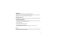
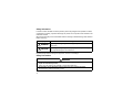
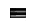
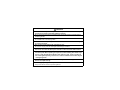
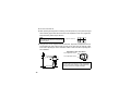
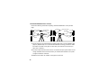
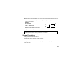
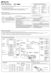
POWER
INSTRUCTION MANUAL
ROTATING LASER
RL-H3A/B
TE
Foreword
Thank you for purchasing the Topcon RL-H3A/B Rotating Laser.
To quickly and effectively use the RL-H3A/B, please read these brief instructions carefully,
and keep them in a convenient location for future reference.
Handling Precautions
Before starting work or operation, be sure to check that the instrument is functioning correctly with normal performance.
1 Vibration and Impact Protection
When transporting the instrument, provide protection to minimize risk of severe vibration or impact.
Severe vibration or impacts may affect beam accuracy.
2 Checking battery power.
Before operating, check remaining battery life.
3 Storing the instrument for long period
Remove the batteries from the instrument when you will not be using it for long period.
Caution:
Use of adjustment controls or performance procedures other than those specified herein
may results in hazardous radiation exposure.
1
Safety Information
In order to ensure the safe use of this product, prevent any danger to the operator or others,
or damage to property, important warnings are placed on the product and inserted in the
instruction manual.
We recommend that you become familiar with the meaning of these Warnings and Cautions
before continuing.
Display
Meaning
WARNING
Ignoring or disregarding of this display may lead to death or serious injury.
CAUTION
Ignoring or disregarding of this display may lead to personal injury
or physical damage to the instrument.
Injury refers to hurt, burn, electric shock, etc.
Physical damage refers to damage to equipment, structure or furnishings.
Safety Precautions
WARNING
• There is a risk of fire,electric shock or physical harm if you attempt to disassemble or
repair the instrument yourself.
This is only to be carried out by TOPCON or an authorized dealer,only!
• Laser beams can be dangerous,and can cause eye injury if used incorrectly .
Never attempt to repair the instrument yourself.
2
• High temperature may cause fire.
Do not cover the charger while it is charging.
• Risk of fire or electric shock.
Do not use damaged power cable, plug and socket.
• Risk of fire or electric shock.
Do not use a wet battery or charger.
• May ignite explosively.
Never use an instrument near flammable gas, liquid matter, and do not use in a coal mine.
• Battery can cause explosion or injury.
Do not dispose in fire or heat.
• Risk of fire or electric shock.
Do not use any power voltage except the one given on manufacturers instructions.
• Battery can cause outbreak of fire.
Do not use any other type of charger other than the one specified.
• Cause eye injury or blindness.
Do not stare into beam or view directly with optical instruments.
•The short circuit of a battery can cause a fire.
Do not short circuit battery when storing it.
3
CAUTION
• Use of controls or adjustment or performance of procedures other than those specified herein may result in hazardous radiation exposure.
• Do not connect or disconnect equipment with wet hands,you are at risk of electric
shocks if you do!
• Risk of injury by overturn the carrying case.
Do not stand or sit on the carrying cases.
• Please note that the tips of tripod can be hazardous,be aware of this when setting up
or carrying the tripod.
• Risk of injury by falling down the instrument or case.
Do not use a carrying case with a damaged which belts,grips or latches .
• Do not allow skin or clothing to come into contact with acid from the batteries, if this
does occur then wash off with copious amounts of water and seek medical advice.
• Let the laser beam reach the aimed object or the target without anybody else in the
laser beam path. When operating in an open area, avoid radiating laser beam at eye
level. It is quite possible for the beam to enter into one's eyes, and it is possible to
lose visual sight temporarily, and lose one's caution and awareness of other dangers
- avoid glaring beam.
• It could be dangerous if the instrument falls over, please check that you fix the instrument to the tripod correctly.
• Risk of injury by falling down a tripod and an instrument.
Always check that the screws of tripod are tightened.
4
User Precautions
Wear the required protectors (safety shoes, helmet, etc.) when operating.
Exceptions from Responsibility
1 The user of this product is expected to follow all operating instructions and make periodic checks of the
product’s performance.
2 The manufacturer, or its representatives, assumes no responsibility for results of a faulty or intentional
usage or misuse including any direct, indirect, consequential damage, and loss of profits.
3 The manufacturer, or its representatives, assumes no responsibility for consequential damage, and
loss of profits by any disaster, (an earthquake, storms, floods etc.), fire, accident, or an act of a third
party and/or a usage in other than usual conditions.
4 The manufacturer, or its representatives, assumes no responsibility for any damage, and loss of profits
due to a change of data, loss of data, an interruption of business etc., caused by using the product or
an unusable product.
5 The manufacturer, or its representatives, assumes no responsibility for any damage, and loss of profits
caused by usage other than explained in the user manual.
6 The manufacturer, or its representatives, assumes no responsibility for damage caused by wrong
movement, or action due to connecting with other products.
5
Laser Safety
This product uses a visible laser beam, and is manufactured and sold in accordance with
“Performance Standards for Light-Emitting Products” (FDA/BRH 21 CFR 1040) or “Radiation
Safety of Laser Products, Equipment Classification, Requirements and User’s Guide” (IEC
Publication 60825-1) provided on the safety standards for laser products.
As per the said standard, RL-H3A standard model is classified as “Class 3R Laser Product”
and RL-H3B model is classified as “Class 1 Laser Products”. In case of any failure, do not
disassemble the instrument. Contact TOPCON or your TOPCON dealer.
RL-H3A
Class 3R Laser Product
Visible Laser Beam
Laser output : Approx. 2.0mw
LASER RADIATION
AVOID DIRECT EYE EXPOSURE
CLASS 3R @LASER PRODUCT
6
Beam aperture
RL-H3B
Class 1 Laser Product
Visible Laser Beam
Laser output : Approx. 0.9mw
Beam aperture
7
Contents
Foreword ............................................................................. 1
Handling Precautions ............................................................ 1
Safety Information ................................................................. 2
Safety Precautions ................................................................ 2
User Precautions ................................................................... 5
Exceptions from Responsibility ............................................. 5
Laser Safety .......................................................................... 6
Contents ................................................................................ 8
Standard System Components ............................................. 9
Nomenclature ..................................................................... 10
Preparation for Use ............................................................ 11
Power Source ........................................................................ 11
Setting Instrument Up ........................................................... 11
Power Key ............................................................................. 11
Battery Status Display ........................................................... 11
Auto-leveling Lamp ............................................................... 12
Height Alert Function ............................................................. 12
How to Operate ................................................................... 13
Operational Example ......................................................... 15
Maintaining Power Sources .............................................. 16
Dry Battery ............................................................................ 16
Replacing Dry Batteries .................................................. 16
Rechargeable Battery ........................................................... 17
Installing .......................................................................... 17
Charging .......................................................................... 17
Checking and Adjusting .................................................... 19
Horizontal Calibration ............................................................ 19
Checking ......................................................................... 19
Adjusting ......................................................................... 21
Horizontal Rotation Error of Cone ......................................... 24
Storage Precautions .......................................................... 25
Standard / Optional Accessories ...................................... 26
Specifications ..................................................................... 30
8
Standard System Components
RL-H3A
1)RL-H3A Instrument .................. 1set
2)Battery unit * .............................. 1set
3)LS-70A/B Laser Sensor ** ........ 1pc.
4)Laser Sensor holder model 6 .... 1pc.
5)Carrying case ............................ 1pc.
6)Instruction manual..................... 1vol.
RL-H3B
1)RL-H3B Instrument ...................1set
2)Battery unit * .............................. 1set
3)LS-70A/B Laser Sensor ** ........ 1pc.
4)Laser Sensor holder model 6 ....1pc.
5)Carrying case ............................1pc.
6)Instruction manual .....................1vol.
*Depending on which power configuaration was
purchased, battery components are below.
*Depending on which power configuaration was
purchased, battery components are below.
**The model of laser sensor included is dependent
on your purchasing option.
**The model of laser sensor included is dependent
on your purchasing option.
Dry battery type
Battery holder DB-57.................... 1pc.
Dry batteries (R20P type)............. 4pcs.
Dry battery type
Battery holder DB-57.................... 1pc.
Dry batteries (R20P type)............. 4pcs.
Rechargeable battery type
Battery holder DB-57C ................. 1pc.
Ni-MH battery pack BT-49Q.......... 1pc.
AC/DC converter AD-9B/7C ......... 1pc.
Rechargeable battery type
Battery holder DB-57C .................1pc.
Ni-MH battery pack BT-49Q..........1pc.
AC/DC converter AD-9B/7C .........1pc.
•Please make sure that all of above items are in the box when you unpack.
9
Nomenclature
Rotary head
Laser emitting window
Control panel
(Beam aperture)
Battery status lamp
Handle
Automatic leveling lamp
Height alert off lamp
POWER
Height alert on/off key
Control panel
Battery compartment lock
Battery holder DB-57C/57
10
Power key
Preparation for Use
Power Source
Connect the battery according to the type of battery purchased.
For handling batteries, see the "Handling Power Sources" chapter.
Setting Instrument Up
Set the instrument on a tripod or smooth surface.
Power Key
Turn the instrument ON or OFF by pressing the power key.
Automatic leveling will start by turning the power switch ON.
Battery Status Display
Battery status will be displayed for several minutes when the instrument is
powered on or when the battery level changes.
Battery is sufficient. (Stays lit for about one minute)
The power is low, but laser is still usable. (Blinking continues until batteries are dead.)
Dead batteries. Recharge the battery or replace the dry batteries with new ones.(The
laser will turn completely off after blinking for about five minutes.)
NOTE:Even if an AC/DC converter is connected at this time, blinking still continues.
Once the power is turned off, the battery status display will reset.
Note: LS-70A/B Laser Sensor can detect low power state of laser.
11
Auto-leveling Lamp
Blinking : Leveling automatically. When automatic leveling is almost complete, blinking
will slow. The rotary head is rotating slowly, and the laser beam is emitting.
On solid : Completes leveling. The rotary head is rotating (600rpm) and emits a laser
beam horizontally.
Intermittent Blinking
: The instrument is inclined beyond the automatic leveling range. The rotary
head is not rotating, nor the laser beam emitting.Turn off and level the
instrument again, then turn on the instrument again.
Note:If auto-leveling is not completed after two or three minutes, turn on the instrument again after relevelling the tripod or surface.
Height Alert Function
If the instrument is disturbed for some reason after automatic leveling is complete, the
height alert function is activated. The auto-leveling lamp and height alert off lamp will
blink at the same time and the LS-70A/B laser sensor will display a warning. Turn the
power key OFF and ON again, the auto-leveling function will start again.You should also
recheck the elevation of the laser beam to confirm it has not changed.
Note:
1) LS-70A/B Laser Sensor can detect the height alert warning.
2)To change ON/OFF of the height alert function
Press the height alert on/off key twice continuously when the height alert function is active, the function
will become inactive and the height alert off lamp will turn on.
If you press the height alert on/off key once again, the function will become active again.
The initial mode of the function in power ON is active.
12
How to Operate
1 Set the instrument on a tripod or smooth surface
and power ON.
2 Turn on LS-70A/B laser sensor.
To change the on-grade precision of the laser sensor, press the on-grade precision mode button.
(page 27)
3 Place the laser sensor in the path of rotating laser
beam.
For more information about Topcon laser sensors,
see pages 26 and 27 in this manual.
13
4 Move the laser sensor up or down until the LCDÅ@
and audible indicators identifies the center of the
laser beam has beam located..
Normal
precision
mode
Higher than datum position
High
precision
mode
Datum position
(Buzzer sound:High frequent beep sound)
Move the sensor downward.
(Buzzer sound:Continuous beep sound)
Lower than datum position
(Buzzer sound:Low frequent beep sound)
Move the sensor upward.
5 Mark the position of index. The center-of-beam
index is 40 mm (1 9/16 inch) from the top of the
sensor if you wish to mark the top of the sensor
and use an offset.
(1 9/16 inch)
14
Operational Example
15
Maintaining Power Sources
Dry Battery
Replacing Dry Batteries
1 Remove the battery cover by turning the battery
cover knob to “OPEN”.
2 As illustrated, remove the old batteries and
replace them with new dry batteries in direction
of
.
3 Replace the battery cover and turn the knob to
“LOCK”.
Note :
Replace all 4 batteries with new ones.
Do not mix old batteries and new ones.
16
Rechargeable Battery
Installing
1 Insert Ni-MH BT-49Q battery pack into the DB57C battery holder.
2 Insert the battery pack into the instrument and
POWER
AC/DC converter
AD-9B/7C
turn the battery compartment lock to “LOCK”.
Charging
1 Plug the AC/DC converter (AD-9B or AD-7C)
into the DB-57C battery holder.
2 Plug the converter power cord into an outlet.
DB-57C
LED
(AD-9B is for AC120V, AD-7C is for AC230V)
3 Complete charging by unplugging the converter connector from the DB-57C battery
holder after approximately 9 hours.
4 Unplug the converter power cord.
The LED of DB-57C will indicate charging status:
Red ON
: Charging.
Green ON
: Charging completed.
Green flashing : BT-49Q battery pack is not installed correctly.
Red flashing
: BT-49Q battery pack protection feature is working automatically.
RL-H3A/B can be used in this state.
Automatic protection feature: In case of overcharge or high or low temperature state exceeding charging range, charging will be stopped or changed to protect battery.
17
Note :
1) The BT-49Q rechargeable battery can be charged while using the laser.
2) The BT-49Q rechargeable battery can be charged when removed from the instrument.
3) When the BT-49Q rechargeable battery cells are removed from the DB-57C battery holder, the
instrument can be used with alkaline batteries installed in the battery pack.
BT-49Q
DB-57C
Note :
1) Recharging should take place in a room with an ambient temperature range of 0°C to 40°C (32°F
to 104°F).
2) The battery source will discharge when stored and should be checked before using with instrument.
3) Be sure to charge stored battery source every 3 or 4 months and store in a place at 30° (86°F) or
below. If you allow the battery to become completely discharged, it will have an effect on future
charging.
Note : This battery does not contain mercury.
18
Checking and Adjusting
Horizontal Calibration
Checking
about 20m(66ft)
X2
Y2
Mark
Y1
A1
about 20m(66ft)
Mark
B1
X1
Wall A
POWER
Laser Sensor
Paper
Laser Sensor
Wall B
Paper
1 Set up the tripod at a midpoint between two walls, A and B. Ideally, the walls should be
40 meters (130 feet) apart. Take care when setting up the tripod to make sure the tripod head as level as possible and that it is securely positioned.
2 Mount the instrument to the tripod so side X2 is facing wall A, and X1 is facing wall B
(see illustration above).Turn power on and allow the instrument to auto-level.
3 Turn on the LS-70 laser sensor and set it to fine precision (see page 27).
4 Attach a piece of paper to each wall so it is approximately centered in the path of the
rotating laser beam. Using the LS-70, locate the exact position of the laser on wall A
and mark the position on the paper. Call this mark A1. Repeat this procedure on wall
B. Call this mark B1.
19
5 Turn the instrument off, loosen the tripod mount and rotate the instrument 180
degrees. Side X1 should now be facing wall A and X2 facing wall B.
X1
Note:
X2
Do not to disturb the position of the tripod
while rotating the instrument.
6 Turn power back on to the instrument and allow it to auto-level.
7 Using the LS-70, locate the excat position of the laser on wall A and mark the position
on the paper. Call this mark A2. Repeat this procedure on wall B. Call this mark B2.
Measure the distance between marks A1 and A2. Measure the distance between
marks B1 and B2. Add the two distances together. If the total distance is less than that
indicated below for your model, no adjust-ment is necessary for the X axis.
RL-H3A: ±3mm or .12 inches
(approximately 1/8 inch)
RL-H3B: ±4mm or .16 inches
(slightly less than 3/16 inch)
A2
1
B1
X1
B2
X2
Wall B
Wall A
Note:
If total distance exceeds 40mm (1.6 inches),
contact your Topcon dealer.
20
about 20m(66ft)
about 20m(66ft)
8 If no adjustment is needed in the X axis, repeat this procedure for the Y-axis using
sides Y1 and Y2.
Adjusting
After checking calibration as described in the previous, follow this procedure if adjustment is required. Be sure not to move the tripod or paper used while checking calibration.
1 Make a calibration reference mark (AX) on wall A as follows:
a.Measure the distance between marks A1 and A2.
Measure the distance between marks B1 and B2.
Add the two distances together. (this is same distance
as determined in step 7)
b.Divide the total by four (4).
c.Starting at mark A2, measure toward mark A1 the distance calculated in step b above and make a new mark
AX.
EXAMPLE:
A1 to A2 is 10mm (0.4 inch)
B1 to B2 is 12mm (0.48 inch)
Total of both distances is 22mm (0.88 inch)
Divided by 4 equals 5.5mm (0.22 or 3/16 inch)
Mark AX is made 5.5mm (3/16 inch) below A2
A2
10mm/0.4in
A1
B1
12mm/0.48in
B2
Total distance equals 22mm / 0.88 inch
Divided by 4 equals 5.5mm / 0.22 inch
A2
AX
Measure from A2
5.5mm / .22 in (3/16)
and mark AX
A1
21
2 Turn the instrument off.
3 While pressing the height alert on/off key, press the power key. Then press the height
alert on/off key again within two seconds to enter adjustment mode. The height alert
lamp and battery status lamps will flash.
Note:
Height Alert On/Off key
Do not disturb the instrument or tripod while
performing step 3.
4 Using the hex wrench supplied with the instrument, adjust the axis adjustment screw
(see illustration at right) until the beam is center on the new mark AX. Use the X axis
screw when adjusting the X-axis calibration andthe Y-axis screw when adjusting the Y
axis calibration.
Instrument as seen from above
X-axis adjustment screw
2
x
X1
X2
Y-axis adjustment screw
Note:
about 20m(66ft)
22
The laser beam is moved up or down approximately 6mm (.25 inch) at a distance of 20m (66 feet) by
turning the screw one complete revolution.
5 Turn the instrument off.
6 Repeat the checking procedure in the previous section to confirm proper calibration
has been obtained.
7 If Y axis adjustment was required, repeat this procedure for the y axis.
23
Horizontal Rotation Error of Cone
Perform the following check after completing "Horizontal Calibration" on the previous
page.
about 20m(66ft)
Mark
Wall A
A1
Laser Sensor
Paper
2m(6.6ft)
about 20m(66ft)
Mark
B1
Laser Sensor
about 38m(125.5ft)
A2
Wall B Wall A
Paper
Mark
B2
Laser Sensor
Wall B
Paper
1 Set up instrument on tripod between two walls as was done to check calibration (see
page 19). Repeat steps 1 to 4 of Horizontal Calibration Checking procedure to make
two marks A1 and B1 on the paper on each wall. (The instrument can be set up in
either X or Y direction.)
2 Turn off the instrument and move it so it is no more than 2m (6.5 ft) from wall A. Do not
change orientation of the instrument and try to maintain same elevation. Turn power
on again and allow to auto-level.
3 Make two new marks, A2 and B2, on the paper on each wall.
24
4 Measure the distance between each set of marks. If the difference between the measurements is less than 4mm (0.16 inch or approximately 5/32 inch), cone error adjustment is not required.
EXAMPLE:
A1 – A2 = 10mm
B2 – B1 = 12mm
12mm – 10mm = 2mm
A1
10mm/0.4in
A2
B2
12mm/0.48in
B1
2mm is less than 4mm so cone error
adjustment is not required.
Note:
If difference exceeds 4mm (0.16 inch), contact your Topcon dealer.
Storage Precautions
Always clean the instrument after use.
Use a clean cloth, moistened with a neutral detergent or water. Never use an abrasive
cleaner, ether, thinner benzene, or other solvents.
Always make sure instrument is completely dry before storing. Dry any moisture with a
soft, clean cloth.
25
Standard / Optional Accessories
Laser sensor holder model 5
Laser sensor holder model 6
Laser sensor holder model 3
160
159
158
157
160
156
159
155
158
154
154
157
153
153
156
152
152
150
Clamp knob
155
151
151
Clamp knob
Clamp knob
154
150
153
149
152
148
151
149
148
147
150
147
146
143
POWER
142
139
138
137
131
139
138
137
131
139
136
138
135
137
134
136
136
135
135
134
134
133
132
131
Laser sensor
holder model 6
133
132
131
133
130
132
129
131
128
130
127
129
Laser sensor
Laser sensor
holder model 5
126
128
125
127
126
125
Laser sensor
Holder model 5 allows sensor to
move on the rod by squeezing a
clamp located in the back side
without the need to loosen the
clamp knob.
26
Laser sensor
holder model 3
LS-70A Laser Sensor
LS-70B/70C Laser Sensor
Indicator
LS-70B:
The indicators are
located on front and
back sides of the
instrument.
LS-70C:
The indicator is
located only on front
side.
Beam receiving window
Beam receiving window
Indicator
Index
Buzzer sound
switch
(Quite/Loud/OFF)
Illumination
switch
Press the detective precision switch while
pressing buzzer sound
switch.
Index
Index
On-grade
precision switch
Index
Two leveling precision
options are available,
normal precision and
high precision. By
pressing this switch, the
precision options are
switched alternately.
Confirm the precision
choice by the indicator.
(Normal precision is set
when turning on the
power switch.)
Power switch
Buzzer speaker
Power switch
Buzzer speaker
Buzzer sound switch
(Quite/Loud/OFF)
Auto-cut off function
The power will be turned off automatically if no laser beam is detected within approximately 30 minutes.
(To turn the sensor on again, press the power switch.)
27
Display (LS-70A/70B)
High precision mode
Height alert warning of rotating laser *1
A flash and a buzzer sound signifies that
the height alert function of rotating laser is
operating.
Laser sensor can detect the signal of
height alert warning of the rotating laser.
The buzzer will sound for about five seconds.
The height alert warning will flash until the
sensor detects normal laser from the rotating laser or the power of the sensor is
turned off.
Rotating laser battery warning *2
A flash shows that the rotating laser power
is low.
The laser sensor can detect the laser battery warning.
Note:
The warning displays *1 and *2 are the
alarm signals that the laser sensor detects from the rotating laser.
This function can be disabled by pressing the buzzer sound switch while you
turn on power to the LS-70 sensor.
Normal precision mode
Higher than datum position
(Buzzer sound:High frequent beep sound)
Move the sensor downward.
Datum position
(Buzzer sound:Continuous beep sound)
Lower than datum position
(Buzzer sound:Low frequent beep sound)
Move the sensor upward.
Battery remaining display
Indicates the battery remaining of LS-70A/
70B as follows.
Battery is sufficient.
The power is low, but sensor still operates.
Dead battery. Replace the dry battery
with new one.
28
Detective Range (LS-70A/70B)
HIGH
Replacing Battery (LS-70A/70B)
NORMAL
1 Press the lid in the direction of the arrow
to lift.
LS-70A
±1mm/±.0032ft
(2mm/.0064ft width)
LS-70B
±1mm/±.0032ft
(2mm/.0064ft width)
±2mm/±.0064mm
(4mm/.013 ft width)
±5mm/±.016ft
(10mm/.032ft width)
2 Take out the battery and
place a new one into the
battery box.
3 Press the lid down and
click to close.
±10mm/±.033ft
(20mm/.066ft width)
Remote Display with Coil Cord
(LS-70A option only)
±15mm/±.05ft
(30mm/.10ft width)
It is possible to view the LCD display of the
laser sensor up to approximately 5m(16ft)
from the laser sensor by using the optional
remote display with the coil cord.
More than ±15mm/±.05ft
Connector
Coil cord
Remote display
Laser sensor has been moved above or
below the laser beam.
Move sensor in direction of arrow to
receive laser.
LS-70A
29
Specifications
Accuracy
RL-H3A
RL-H3B
Auto-leveling range
Measuring range (Diameter)
RL-H3A
RL-H3B
Rotation speeds
Light source
Battery remaining warning
Power supply
: ±1.9mm(0.074in)/50m(164ft)
: ±2.4mm(0.094in)/50m(164ft)
: ±3°
:
:
:
:
:
:
:
(±8”) (±8 arc seconds)
(±10”) (±10 arc seconds)
Approx.2~700m(6.5~2300ft) (with LS-70A/B)
Approx.2~400m(6.5~1300ft) (with LS-70A/B)
600 (rpm)
L.D (Visible laser)
LED flashing
4D-CELL alkaline batteries (DC6V)
Ni-MH battery pack BT-49Q with run/charge feature
Continuous operating time
RL-H3A
RL-H3B
RL-H3A
RL-H3B
Tripod screw
Protection against water and dust
Operating temperature
Dimensions
Weight
30
With disposable alkaline batteries
: Approx.120 hours
: Approx.120 hours
With rechargeable Ni-MH battery pack BT-49Q
: Approx.60 hours
: Approx.60 hours
: Flat and dome head type, 5”/8X11threads
: IP56(Based on the standard IEC60529)
: -20°C ~ +50°C (-4°F ~ +122°F)
: 220(L)X144(W)x241(H) mm [8.6(L)x 5.6(W)x9.4(H) in]
: 2.6 kg (5.7 lbs) (with alkaline batteries installed)
: 2.8 kg (6.1 lbs) (with rechargeable battery pack BT-49Q installed)
LS-70A/B Laser Sensor
Detective range
:
50mm (2.0 in)
Detective precision
:
High precision:±1mm(±0.04 in)
Normal precision:±2mm(±0.08 in)
Detective beam indication
:
Liquid crystal and buzzer
Power source
:
DC 9V dry battery
Auto shut-off delay
:
Approx. 30 minutes without beam detection.
Operating temperature
:
-20°C to +50°C (-4°F to +122°F)
Continuous operating time at +20°C (68°F)
Alkaline manganese dry batteries
:
Approx. 80 hours
LS-70A
:
167(l) × 78(w) × 27(h) mm
[ 6.6(L) × 3.1 (W) × 1.1(H) in]
LS-70B
:
165(l) × 78(w) × 26(h) mm
[ 6.5(L) × 3.1 (W) × 1.0(H) in]
Weight
:
0.25 kg [0.55 lbs] (with dry batteries)
Remote display connector
:
Optional for LS-70A only
Dimensions
31
TOPCON POSITIONING SYSTEMS, INC.
5758 West Las Positas Blvd., Pleasanton, CA 94588, U.S.A.
Phone: 925-460-1300 Fax: 925-460-1315 www.topcon.com
TOPCON CALIFORNIA
3380 Industrial Blvd, Suite 105, West Sacramento, CA 95691, U.S.A.
Phone: 916-374-8575 Fax: 916-374-8329
TOPCON MIDWEST
891 Busse Road, Elk Grove Village, IL 60007, U.S.A.
Phone: 847-734-1700 Fax: 847-734-1712
TOPCON EUROPE B.V.
Essebaan 11, 2908 LJ Capelle a/d IJssel, The Netherlands.
Phone: 010-4585077 Fax: 010-4585045 www.topconeurope.com
Preenakker 8, 1785 Merchtem, Belgium
Phone: 052-37.45.48 Fax: 052-37.45.79
Weidkamp 180, 45356 Essen, GERMANY
Phone: 0201-8619-100 Fax: 0201-8619-111 [email protected]
www.topcon.de
TOPCON S.A.R.L.
89, Rue de Paris, 92585 Clichy, Cedex, France.
Phone: 33-1-41069490 Fax: 33-1-47390251 [email protected]
TOPCON ESPAÑA S.A.
HEAD OFFICE
Frederic Mompou 5, ED. Euro 3, 08960, Sant Just Desvern Barcelona, Spain.
Phone: 93-473-4057 Fax: 93-473-3932 www.topconesp.com
TOPCON SCANDINAVIA A. B.
Neongatan 2 S-43151 Mölndal, SWEDEN
Phone: 031-7109200 Fax: 031-7109249
Topcon House Kennet Side, Bone Lane, Newbury, Berkshire RG14 5PX U.K.
Phone: 44-1635-551120 Fax: 44-1635-551170
[email protected] [email protected]
TOPCON SINGAPORE PTE. LTD.
Blk 192 Pandan Loop, Pantech Industrial Complex, #07-01, Singapore 128381
Phone: 2780222 Fax: 2733540 www.topcon.com.sg
TOPCON AUSTRALIA PTY. LTD.
408 Victoria Road, Gladesville, NSW 2111, Australia
Phone: 02-9817-4666 Fax: 02-9817-4654 www.topcon.com.au
TOPCON INSTRUMENTS (THAILAND) CO., LTD.
TOPCON INSTRUMENTS (MALAYSIA) SDN. BHD.
TOPCON DEUTSCHLAND G.m.b.H.
Avenida Burgos, 16E, 1∞28036, Madrid, Spain.
Phone: 91-302-4129 Fax: 91-383-3890
HEAD OFFICE
77/162 Sinn Sathorn Tower, 37th Fl.,
Krungdhonburi Rd., Klongtonsai, Klongsarn, Bangkok 10600 Thailand.
Phone: 662-440-1152~7 Fax: 662-440-1158
TOPCON BELGIUM
MADRID OFFICE
TOPCON (GREATBRITAIN) LTD.
Lot 226 Jalan Negara 2, Pusat Bandar Taman Melawati,
Taman Melawati, 53100, Kuala Lumpur, Malaysia.
Phone: 03-41079801 Fax: 03-41079796
TOPCON KOREA CORPORATION
2F Yooseoung Bldg., 1595-3, Seocho-Dong, Seocho-gu, Seoul, 137-876, Korea.
Phone: 82-2-2055-0321 Fax: 82-2-2055-0319 www.topcon.co.kr
TOPCON OPTICAL (H.K.) LIMITED
2/F., Meeco Industrial Bldg., No. 53-55 Au Pui Wan Street, Fo Tan Road,
Shatin, N.T., Hong Kong
Phone: 2690-1328 Fax: 2690-2221 www.topcon.com.hk
TOPCON CORPORATION BEIJING OFFICE
Room No. 962 Poly Plaza Building, 14 Dongzhimen Nandajie,
Dongcheng District, Beijing, 100027, China
Phone: 10-6501-4191~2 Fax: 10-6501-4190
TOPCON CORPORATION BEIRUT OFFICE
P. O. BOX 70-1002 Antelias, BEIRUT-LEBANON.
Phone: 961-4-523525/961-4-523526 Fax: 961-4-521119
TOPCON CORPORATION DUBAI OFFICE
P.O.Box 28595, 102, Al Naily Bldg., 245 Abu Hail Road, Deira,Dubai,UAE
Phone: 971-4-2696511 Fax: 971-4-2695272
TOPCON CORPORATION
75-1 Hasunuma-cho, Itabashi-ku, Tokyo 174-8580, Japan
Phone: 3-3558-2520 Fax: 3-3960-4214 www.topcon.co.jp
RL-H3A/B[TE]
31330 90040
0112 (1a) SAN