1
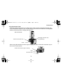
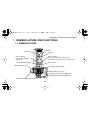
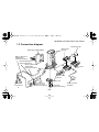
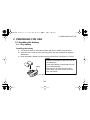
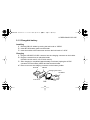
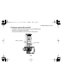
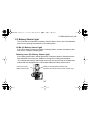
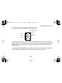
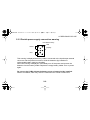
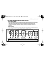
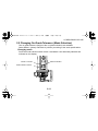
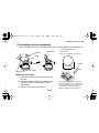
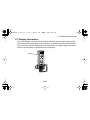
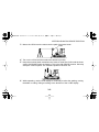
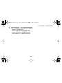
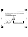
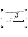
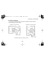
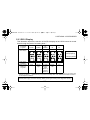
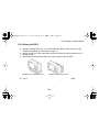
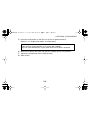
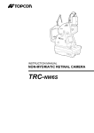
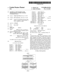
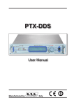
LS-B4E-1.book -1ページ 2001年5月18日 金曜日 午前11時59分
INSTRUCTION MANUAL
LASER SENSOR
LS-B4
LS-B4E-1.book 0 ページ 2001年5月18日 金曜日 午前11時59分
LS-B4E-1.book 1 ページ 2001年5月18日 金曜日 午前11時59分
FOREWORD
FOREWORD
Thank you for purchasing the TOPCON LS-B4 Laser Sensor.
For superior product performance, please read these instructions carefully and keep them
in a convenient place for future reference.
GENERAL HANDLING PRECAUTIONS
Before starting work or operation, be sure to check that the system is functioning properly.
Guarding the instrument against shocks.
When transporting the instrument, provide some protection to minimize risk of shocks.
Heavy shocks may cause faulty measurement. When carrying this instrument, hold the
hand grip.
Protecting the instrument from sudden temperature changes.
Any sudden change in temperature of the instrument may result in a reduction of the
measuring range. When taking the instrument out from a heated vehicle, let it acclimate
itself to the ambient temperature.
Checking battery power.
Before operating, check remaining battery life.
1
LS-B4E-1.book 2 ページ 2001年5月18日 金曜日 午前11時59分
FOREWORD
Protecting the instrument from water damage.
When washing the instrument, avoid spraying it with a high pressure stream of water
from a water hose. The inside of the instrument will be damaged by the water.
This instrument is designed based on the International Standard IPX 6, but it is not
protected from a high pressure water stream or submergence.
Cleaning
Always clean the detector. The dust may cause faulty measurement.
Affection of the radio waves
When using the instrument in the following place, the strong radio wave may cause faulty
operation.
• Near the instrument occurring strong radio waves. (e.g.Transceiver)
• Near the radio wave towers such as television or radio.
2
LS-B4E-1.book 3 ページ 2001年5月18日 金曜日 午前11時59分
FOREWORD
Using Connector Caps
When the external connector is not being used, make sure the protective is placed over
it as shown below. Keep the cap over the charging connector on the DB-54C rechargeable
battery pack except when charging the batteries.
DB-54C+BT-54Q
Charging connector cap
(only DB-54C)
External connector cap
Hook
When using the external connector (input /output), be sure to store the connector cap on
the hook as shown below.
External connector (Input / Output)
LOCK
Hook
Connector cap
3
OPEN
LS-B4E-1.book 4 ページ 2001年5月18日 金曜日 午前11時59分
FOREWORD
SAFETY NOTICES
In order to encourage the safe use of products and prevent any danger to the operator
and others or damage to property, important warnings are put on the products and
inserted in the instruction manual.
We suggest that everyone understand the meaning of the following symbols and
notices before reading the Safety Cautions and text.
Display
Meaning
WARNING
Ignoring or disregard of this display may lead to the danger of death or serious injury.
CAUTION
Ignoring or disregard of this display may lead to personal injury or physical
damage.
•Injury refers to hurt, burn, electric shock, etc.
•Physical damage refers to extensive damage to equipment and structure or furnishings.
4
LS-B4E-1.book 5 ページ 2001年5月18日 金曜日 午前11時59分
FOREWORD
SAFETY CAUTIONS
WARNING
• There is a risk of fire, electric shock or physical harm if you attempt to disassemble or repair the instrument yourself.
This is only to be carried out by TOPCON or an authorized dealer, only !
• Risk of fire or electric shock.
Do not use a wet battery or charger.
• Risk of fire or electric shock .
Do not use damaged power cable, plug and socket.
• Battery can cause explosion or injury.
Do not dispose in fire or heat.
• May ignite explosively.
Never use an instrument near flammable gas, liquid matter, and do not use in a coal mine.
• The short circuit of a battery can cause a fire.
Do not short circuit battery when storing it.
CAUTION
• Do not allow skin or clothing to come into contact with acid from the batteries, if this does occur then
wash off with large amounts of water and seek medical advice.
• Do not use a damaged instrument case. It could accidentally open causing damage to the instrument or
injury to people.
5
LS-B4E-1.book 6 ページ 2001年5月18日 金曜日 午前11時59分
FOREWORD
USER
Wear the required protectors (safety shoes, helmet, etc.) when operating.
EXCEPTIONS FROM RESPONSIBILITY
1)The user of this product is expected to follow all operating instructions and make periodic checks of the product’s performance.
2)The manufacturer, or its representatives, assumes no responsibility for results of a
faulty or intentional use or misuse including any direct, indirect, consequential damage,
and/or loss of profits.
3)The manufacturer, or its representatives, assumes no responsibility for consequential
damage and loss of profits by any disaster, (earthquake, storm, flood etc.), a fire, accident, or an act of a third party and/or use outside the instrument's intended conditions.
4)The manufacturer, or its representatives, assumes no responsibility for any damage, and
loss of profits due to a change of data, loss of data, an interruption of business etc.,
caused by using the product or an unusable product.
5)The manufacturer, or its representatives, assumes no responsibility for any damage,
and loss of profits caused by use except for as explained in the user manual.
6)The manufacturer, or its representatives, assumes no responsibility for damage caused
by wrong movement or action due to connecting with other products.
6
LS-B4E-1.book 7 ページ 2001年5月18日 金曜日 午前11時59分
FOREWORD
CONTENTS
FOREWORD . . . . . . . . . . . . . . . . . . . . . . . . . . . . . . . . . . . . . . . . . . . . . . 1
GENERAL HANDLING PRECAUTIONS . . . . . . . . . . . . . . . . . . . . . . . . . . . . . 1
SAFETY NOTICES . . . . . . . . . . . . . . . . . . . . . . . . . . . . . . . . . . . . . . . . . . . . . 4
SAFETY CAUTIONS . . . . . . . . . . . . . . . . . . . . . . . . . . . . . . . . . . . . . . . . . . . . 5
CONTENTS . . . . . . . . . . . . . . . . . . . . . . . . . . . . . . . . . . . . . . . . . . . . . . . . . . . 7
STANDARD SYSTEM COMPONENTS . . . . . . . . . . . . . . . . . . . . . . . . . . . . . 9
1 NOMENCLATURE AND FUNCTIONS . . . . . . . . . . . . . . . . . . . . . . . 1-1
1.1 NOMENCLATURE . . . . . . . . . . . . . . . . . . . . . . . . . . . . . . . . . . . . . . . . . 1-1
1.2 FUNCTIONS . . . . . . . . . . . . . . . . . . . . . . . . . . . . . . . . . . . . . . . . . . . . . 1-2
1.3 Connection diagram . . . . . . . . . . . . . . . . . . . . . . . . . . . . . . . . . . . . . . . . 1-3
2 PREPARING FOR USE . . . . . . . . . . . . . . . . . . . . . . . . . . . . . . . . . . . 2-1
2.1 Handling the battery . . . . . . . . . . . . . . . . . . . . . . . . . . . . . . . . . . . . . . . . 2-1
2.1.1 Dry battery . . . . . . . . . . . . . . . . . . . . . . . . . . . . . . . . . . . . . . . . . . . . . . . . . . 2-1
2.1.2 Chargable battery . . . . . . . . . . . . . . . . . . . . . . . . . . . . . . . . . . . . . . . . . . . . 2-2
2.2 Power switch ON and OFF . . . . . . . . . . . . . . . . . . . . . . . . . . . . . . . . . . 2-6
2.3 Battery Status Light . . . . . . . . . . . . . . . . . . . . . . . . . . . . . . . . . . . . . . . . 2-7
2.3.1 Rotating laser height alert warning*. . . . . . . . . . . . . . . . . . . . . . . . . . . . . . . 2-8
2.3.2 Double power supply connection warning . . . . . . . . . . . . . . . . . . . . . . . . . . 2-9
2.4 Power Saving Mode and Auto Shut-Off . . . . . . . . . . . . . . . . . . . . . . . . 2-10
2.5 Changing On-Grade Tolerance (Mode Selection) . . . . . . . . . . . . . . . . 2-11
7
LS-B4E-1.book 8 ページ 2001年5月18日 金曜日 午前11時59分
FOREWORD
2.6 Installing on the equipment . . . . . . . . . . . . . . . . . . . . . . . . . . . . . . . . . 2-12
2.7 Display Information . . . . . . . . . . . . . . . . . . . . . . . . . . . . . . . . . . . . . . . 2-13
3 ESTABLISHING ON-GRADE POSITION . . . . . . . . . . . . . . . . . . . . . 3-1
4 CARE & CLEANING . . . . . . . . . . . . . . . . . . . . . . . . . . . . . . . . . . . . . 4-1
5 OPTIONAL ACCESSORIES . . . . . . . . . . . . . . . . . . . . . . . . . . . . . . . 5-1
5.1 Connection to other instruments . . . . . . . . . . . . . . . . . . . . . . . . . . . . . . 5-2
5.1.1 Connecting the RD-2 and LS-B4 . . . . . . . . . . . . . . . . . . . . . . . . . . . . . . . . . 5-2
5.1.2 Using the machine battery to power LS-B4 . . . . . . . . . . . . . . . . . . . . . . . . . 5-3
5.2 RD-2 Remote Display . . . . . . . . . . . . . . . . . . . . . . . . . . . . . . . . . . . . . . 5-4
5.2.1
5.2.2
5.2.3
5.2.4
Nomenclature . . . . . . . . . . . . . . . . . . . . . . . . . . . . . . . . . . . . . . . . . . . . . . . . 5-4
RD-2 Installation . . . . . . . . . . . . . . . . . . . . . . . . . . . . . . . . . . . . . . . . . . . . . 5-5
RD-2 Display . . . . . . . . . . . . . . . . . . . . . . . . . . . . . . . . . . . . . . . . . . . . . . . . 5-6
Using the RD-2 . . . . . . . . . . . . . . . . . . . . . . . . . . . . . . . . . . . . . . . . . . . . . . 5-7
6 SPECIFICATIONS . . . . . . . . . . . . . . . . . . . . . . . . . . . . . . . . . . . . . . . 6-1
8
LS-B4E-1.book 9 ページ 2001年5月18日 金曜日 午前11時59分
FOREWORD
STANDARD SYSTEM COMPONENTS
Types
Components
Chargable
battery type
Dry
battery type
Laser Tracker
package
(A model)
(B model)
(C model)
Instrument (LS-B4)
1pc.
1pc.
1pc.
DB-54C Battery holder
(For rechargable and dry battery.)
1pc.
-
-
-
1pc.
-
DB-54 Battery holder
(Only for dry battery)
Battery cover
BT-54Q Ni-MH rechargeable battery
D size dry battery
-
-
1pc.
1pc.
-
-
-
2pc.
-
AD-9B/7C AC-DC convertor / battery charger
1pc.
-
-
Hard case
1pc.
1pc.
-
Soft case
-
-
1pc.
Instruction manual
1vol.
1vol.
1vol.
Warranty card
1vol.
1vol.
1vol.
Make sure that all of the above items are with the instrument when purchased.
If you purchased the LS-B4 Laser Tracker package (C model) all package components are stored
in the incleded soft carrying case.
9
LS-B4E-1.book 1 ページ 2001年5月18日 金曜日 午前11時59分
1NOMENCLATURE AND FUNCTIONS
1 NOMENCLATURE AND FUNCTIONS
1.1 NOMENCLATURE
Detector
Detector
Display
Mode 2 indicator /
Rotating Laser(RL) Battery Status Light
(operates with specific Topcon laser models only)
Mode 1 indicator /
Laser sensor(LS) Battery
Status Light
Mode Selection Switch
Power Switch
Battery Holder Lock
Hand Grip / Mast Clamp
Battery Holder ( or cover)
Charging Connector (only DB-54C)
Charging Status LED (only DB-54C)
External Connector (input/output)
1-1
LS-B4E-1.book 2 ページ 2001年5月18日 金曜日 午前11時59分
1NOMENCLATURE AND FUNCTIONS
1.2 FUNCTIONS
When this instrument is used with a rotating laser, the display (red, yellow and green
LED's) indicate the direction the cutting edge of the machine should be moved in order
to obtain the preset on-grade position.
This instrument can also be used in conjunction with the Trackerjack (Laser Tracker
package, C model) as the primary rotating laser receiver for any Topcon equipment
automation system (System Five, System Four, Touch Series 5, etc).
1-2
LS-B4E-1.book 3 ページ 2001年5月18日 金曜日 午前11時59分
1NOMENCLATURE AND FUNCTIONS
1.3 Connection diagram
D-size Dry cell
Battery Pack
Hand Grip / Mast Clamp
LS-B4 BT-54Q
Battery cable PC-18
(#9060-5033)
(Optional accessory)
Remote display RD-2
(Optional accessory)
Battery cable PC-20
(#9060-5087)
(Optional accessory)
K
LOC
K
LOC
Battery holder
DB-54
K
LOC
Battery holder
DB-54C
Battery cover
Battery of
the machine
Joint cable JC-7
(#9063-1035-20)
(Optional accessory)
Trackerjack
(Optional accessory)
1-3
AC/DC converter
AD-9B/7C
LS-B4E-1.book 1 ページ 2001年5月18日 金曜日 午前11時59分
2 PREPARING FOR USE
2 PREPARING FOR USE
2.1 Handling the battery
2.1.1 Dry battery
Installing the battery
1 Turn the lock konb on the battery holder (DB-54) to “OPEN” and remove it.
2 Insert the two D-size dry cells, matching them with the positive and negative
illustrations.
3 Insert the battery holder into the instrument and turn the lock konb to “LOCK”.
NOTE
•Replace both batteries with new ones at
the same time.
•Insert the batteries in the holder according to the illustration.
•Remove the dry cells from the instrument when you will not use it for more
than one month.
DB-54
CK
LO
Lock Knob
2-1
LS-B4E-1.book 2 ページ 2001年5月18日 金曜日 午前11時59分
2 PREPARING FOR USE
2.1.2 Chargable battery
Installing
1 Remove DB-54C holder by turning the lock knob to “OPEN”.
2 Insert BT-54Q battery pack into the holder.
3 Insert the holder to the instrument and turn the lock knob to “LOCK”.
Charging
1 Plug the AD-9B/7C AC/DC convertor into the charging connector on the holder.
2 Plug the convertor into an electrical outlet.
(AD-9B:110-120 volt AC, AD-7C:230 volt AC)
3 After charging is completed (approximately nine hours) unplug the AC/DC
converter from the battery holder and the electrical outlet.
4 Place cover over the charging connector on the battery holder.
BT-54Q
DB-54C
Charging Connector
AD-9B/7C
Lock Knob
2-2
LS-B4E-1.book 3 ページ 2001年5月18日 金曜日 午前11時59分
2 PREPARING FOR USE
The LED on the battery pack indicates charging status as follows:
Red ON
Green ON
Green flashing
Red flashing
:Charging
:Charging completed.
:BT-54Q isn‘t installed on DB-54C correctly.
:Indicates rechargeable battery protection feature* is active. See note
on next page for proper charging conditions.
*Battery protection feature:
In case of overcharge or high or low ambient temperatures that exceeds charging temperature range, charging will be stopped or changed to protect battery.
•You can charge the battery pack(BT-54Q) while the battery holder(DB-54C) is installed on the
instrument(LS-B4).
•Dry batteries (two D-cell alkaline) can be used by removing the battery pack (BT-54Q) and placing
them in battery holder (DB-54C) as shown in the illustration on page 2-1.
2-3
LS-B4E-1.book 4 ページ 2001年5月18日 金曜日 午前11時59分
2 PREPARING FOR USE
Note
• Recharging should take place in a room with an ambient temperature range of 10°C to 35°C (50°F
to 95°F).
• Exceeding the specified charging time may shorten the life of the battery and should be avoided if
possible.
• The battery source will discharge when stored and should be checked before using with instrument.
• Be sure to charge a stored battery source every 3 or 4 months and store in a place at 30 °C (86 °F)
and below when it will not used for a long period.
If you allow the battery to be completely discharged, it will have an effect on the overall performance for proper charging in the future.
• Recharging can take less than 9 hours depending on the discharge condition of the battery when
charging begins.
2-4
LS-B4E-1.book 5 ページ 2001年5月18日 金曜日 午前11時59分
2 PREPARING FOR USE
Before connecting any cable to the input/output external connector of this instrument,
remove the batteries (dry batteries or chargeable battery pack).
If a cable is connected to the input/output external connector and the power is turned on
while the batteries are installed, “Double power supply connection warning” is displayed
(refer to “2.3.2 Double power supply connection warning”). Immediately turn off the
power and remove the batteries from the battery holder. Replace the empty battery
holder. Then, turn on the power again.
Do not use the LS-B4 without the battery cover or battery holder installed.
Without it installed, water may enter the instrument and cause a malfunction.
2-5
LS-B4E-1.book 6 ページ 2001年5月18日 金曜日 午前11時59分
2 PREPARING FOR USE
2.2 Power switch ON and OFF
The power can be turned on by pressing the POWER switch.
The Mode 1 indicator will illuminate.
Pressing the POWER switch again turns off the power.
Mode 1 indicator
Power switch
2-6
LS-B4E-1.book 7 ページ 2001年5月18日 金曜日 午前11時59分
2 PREPARING FOR USE
2.3 Battery Status Light
The LS-B4 has two separate low battery indicator lights, one for the LS-B4 batteries
and one for indicating low batteries in the rotating laser *.
LS-B4 (LS Battery Status Light)
If the LS-B4 battery status light (Mode 1 indicator) blinks, replace the batteries with
new ones or charge the battery pack.
Rotating Laser (RL Battery Status Light)*
If the rotating laser battery status light (Mode 2 indicator) blinks it indicates that the
laser batteries are running low. Replace or charge the rotating laser batteries.
*The rotating laser battery status light works only with specific Topcon rotating laser
models that are equipped with a sensor-detectable low battery alert function.
Laser sensor(LS)
Battery Status Light
Rotating Laser(RL) Battery Status Light
(operates with specific Topcon laser models only)
2-7
LS-B4E-1.book 8 ページ 2001年5月18日 金曜日 午前11時59分
2 PREPARING FOR USE
2.3.1 Rotating laser height alert warning*
LED: Blinks slowly
LED
Yellow
Display
Green
Red
If the display illuminates as shown above, the rotating laser has been disturbed and a
substantial change in its position could have occurred. This change has been detected
by the LS-B4. The laser position should be checked to prevent possible erroneous
measurements.
*The rotating laser height alert warning works only with specific Topcon rotating laser
models that are equipped with a sensor-detectable height alert function.
2-8
LS-B4E-1.book 9 ページ 2001年5月18日 金曜日 午前11時59分
2 PREPARING FOR USE
2.3.2 Double power supply connection warning
LED: Blinks slowly
LED
Yellow
Display
Red
This warning is displayed when any cable is connected to the input/output external
connector and the power is turned on while the batteries (dry batteries or
rechargeable battery pack) are installed.
When this warning is displayed, immediately turn off the power and remove the
batteries from the battery holder. Replace the empty battery holder. Turn on power
again.
Do not use the LS-B4 without the battery cover or battery holder installed.
Without it installed, water may enter the instrument and cause a malfunction.
2-9
LS-B4E-1.book 10 ページ 2001年5月18日 金曜日 午前11時59分
2 PREPARING FOR USE
2.4 Power Saving Mode and Auto Shut-Off
Power Saving Mode
If the LS-B4 does not receive a laser signal within a three minute period, it automatically enters Power Saving Mode, which is indicated by a blinking center LED.
To return to full power, vibrate the LS-B4 by moving the equipment where it is
mounted.
Auto Shut-Off
If the LS-B4 does not receive a laser signal within an one hour time period, power is
automatically shut off. To restore power, press the POWER switch.
Display of Power Saving Mode and Auto Shut Off
Blink
Display
Yellow
After one hour
Blink
Green
After
three
minutes
Receiving laser signal
Laser signal ceases
Vibration
Saving mode active
Power is restored
Power off
The auto shut-off functions when the dry cell or charging battery is used, but is disabled when a cable is connected to the external connector on the LS-B4.
2-10
LS-B4E-1.book 11 ページ 2001年5月18日 金曜日 午前11時59分
2 PREPARING FOR USE
2.5 Changing On-Grade Tolerance (Mode Selection)
Two on-grade tolerance (height of the on-grade indication) are available.
Select Mode 1 (±6mm) and Mode 2 (±20mm) according to the work specifications.
Changing mode
Press the mode selection switch. Mode 1 and Mode 2 are alternately selected and
indicated on the display.
Mode 1 indicator
Mode 2 indicator
Mode selection switch
2-11
LS-B4E-1.book 12 ページ 2001年5月18日 金曜日 午前11時59分
2 PREPARING FOR USE
2.6 Installing on the equipment
Use the clamp on the rear of LS-B4 to mount it to a mast installed on the equipment.
LS-B4 Mast Speciation
Clamp Knob
Bracket
1
2
Shape: Round
Size: 1.5”~2” diameter (38~51mm)
3
Mast
Clamp
LS-B4
1.5~2 inches
Mast
Clamp Screw
LS-B4
Mounting onto mast
1 Place the clamp on the mast and close the
bracket.
2 Slide the clamp screw into the bracket and
orient the LS-B4 so the display can be
seen easily.
3 Tighten the clamp knob securely.
2-12
When installing the mast to the equipment (by welding, etc.), refer to the equipment instruction manual or contact the
manufacturer. Contact your Topcon
dealer for Topcon mast accessories.
LS-B4E-1.book 13 ページ 2001年5月18日 金曜日 午前11時59分
2 PREPARING FOR USE
2.7 Display Information
The LS-B4 display is a high-intensity colored LED array that provides a visual guide
for positioning the cutting edge of the machine to a predetermined on-grade elevation.
As the LS-B4 is moved through path of the laser beam, the display will provide seven
channels of information as described on the next page.
Display
2-13
LS-B4E-1.book 14 ページ 2001年5月18日 金曜日 午前11時59分
2 PREPARING FOR USE
This illustration depicts the reaction of LS-B4 display as the sensor is moved down
through the path of a rotating laser.*
Blade
direction to
achieve
on-grade*
DOWN
DOWN
DOWN
ONGRADE
UP
UP
UP
LED display
indication
Blinks
slowly
(yellow)
Blinks
quickly
(yellow)
Blinks
quickly
(green)
Blinks
quickly
(red)
Very High
Slightly
High
On-grade**
to within:
±6mm
(Mode 1)
±20mm
(Mode 2)
Slightly
Low
Blinks
quickly in
sequence
(red)
Low
Blinks
slowly
(red)
Blade position
relative to
on-grade
Blinks
quickly in
sequence
(yellow)
High
LED Color
Yellow
Green
Red
Sensor is
above laser
beam*
Very Low
Sensor is
below laser
beam*
* This illustration is for reference only. Actual blade direction adjustment could vary based on the motion and attitude of machine.
** Tolerance may vary based on rotating laser used, distance from laser instrument or atmospheric conditions.
2-14
LS-B4E-1.book 1 ページ 2001年5月18日 金曜日 午前11時59分
3 ESTABLISHING ON-GRADE POSITION
3 ESTABLISHING ON-GRADE POSITION
1 Position a rotating laser as shown below and turn on the laser.
Rotating laser
2 Raise or lower the machine blade to position the cutting edge at the desired
grade elevation.
Blade
Desired grade elevation
3-1
LS-B4E-1.book 2 ページ 2001年5月18日 金曜日 午前11時59分
3 ESTABLISHING ON-GRADE POSITION
3 Mount the LS-B4 onto the mast near the path of the laser beam.
LS-B4
4 Turn on the LS-B4 and then select the tolerance (mode).
5 Keep the machine blade motionless and raise or lower the LS-B4 until the three
center ON-GRADE lights are flashing. This is the ON-GRADE position. Securely
clamp the LS-B4 in place. The reference position has been set.
6 While operating, use the LED display to continually monitor the grading, moving
the blade or cutting / filling according to the direction of the LS-B4 display.
3-2
LS-B4E-1.book 1 ページ 2001年5月18日 金曜日 午前11時59分
4 CARE & CLEANING
4 CARE & CLEANING
• Always clean the instrument after use.
• Remove the dust using a brush, then wipe off with a soft cloth.
• Never use thinner or benzine to clean the surface of a receiving window or any
plastic parts. Use a clean cloth moistened with neutral detergent.
• Always make sure the instrument is completely dry before storing. Dry any moisture
with a soft, clean cloth.
4-1
LS-B4E-1.book 1 ページ 2001年5月18日 金曜日 午前11時59分
5 OPTIONAL ACCESSORIES
5 OPTIONAL ACCESSORIES
•Remote Display RD-2
•Power Cable PC-20 (#9060-5087)
•Power Cable PC-18 (#9060-5033)
•Joint Cable JC-7 (#9063-1035-20)
5-1
LS-B4E-1.book 2 ページ 2001年5月18日 金曜日 午前11時59分
5 OPTIONAL ACCESSORIES
5.1 Connection to other instruments
Connect LS-B4 to other instruments and power supply as follows.
When connecting LS-B4 to the battery of a machine, connect the red clip of the power
cable (PC-18 or PC-20) to the positive side of the battery and the black clip to the
negative side (or ground).
5.1.1 Connecting the RD-2 and LS-B4
R
WE
PO
DE
MO
PC-18
(#9060-5033)
Black
JC-7
(#9063-1035-20)
Red
RD-2
Connect the RD-2 remote display to the LS-B4 with
the JC-7 junction cable as shown. Connect the PC18 power cable to the machine battery. When RD-2
is connected, LS-B4 power switch is disabled.
Battery of
the machine
5-2
LS-B4E-1.book 3 ページ 2001年5月18日 金曜日 午前11時59分
5 OPTIONAL ACCESSORIES
5.1.2 Using the machine battery to power LS-B4
WER
PO
DE
MO
PC-20 (#9060-5087)
Black
Red
When the LS-B4 is connected to the machine's
battery, power automatically supplied to the LS-B4
and the power switch is disabled.
Battery of
the machine
5-3
LS-B4E-1.book 4 ページ 2001年5月18日 金曜日 午前11時59分
5 OPTIONAL ACCESSORIES
5.2 RD-2 Remote Display
The RD-2 allows the LS-B4 display to monitored in a convenient location, such as in
the cab of a dozer.
5.2.1 Nomenclature
Mode indicator
Power switch
Connector for LS-B4
Power supply connector
Display
Mode selection
switch
Control key
(For use with expanded control systems. Inactive with the
LS-B4 as described in this booklet.)
5-4
LS-B4E-1.book 5 ページ 2001年5月18日 金曜日 午前11時59分
5 OPTIONAL ACCESSORIES
5.2.2 RD-2 Installation
On a vertical or horizontal surface of a machine, install RD-2 using its optional
mounting hardware as shown below.
Installation on horizontal surface
Installation on vertical surface
RD/IR-2 adapter
RD/IR-2 adapter
The RD/IR-2 adapter is an optional accessory
5-5
LS-B4E-1.book 6 ページ 2001年5月18日 金曜日 午前11時59分
5 OPTIONAL ACCESSORIES
5.2.3 RD-2 Display
This illustration depicts the reaction of the RD-2 display as the LS-B4 sensor is moved
down through the path of a rotating laser.*
Blade direction
to achieve
on-grade*
DOWN
DOWN
ONGRADE
UP
UP
LED Display
Display steps:
5 steps (RD-2)
7 steps (LS-B4)
LED display
indication
Blade position
relative to
on-grade
Solid
Blinks
Solid
Blinks
Solid
High
Slightly
High
On-grade**
to within:
±6mm
(Mode 1)
±20mm
(Mode 2)
Slightly
Low
Low
* This illustration is for reference only. Actual blade direction adjustment could vary based on the motion and
attitude of machine. ** Tolerance may vary based on rotating laser used, distance from laser instrument
or atmospheric conditions.
The following indications are not displayed on the RD-2:
Double power supply connection warning; Battery power light; Rotating laser height alert warning.
5-6
LS-B4E-1.book 7 ページ 2001年5月18日 金曜日 午前11時59分
5 OPTIONAL ACCESSORIES
5.2.4 Using the RD-2
1 Set up a rotating laser, turn it on and position the blade of the machine at the
references elevation as described on page 3-1.
2 Mount the LS-B4 on the mast and connect the LS-B4 to the RD-2 with the JC-7
junction cable.
3 Set the RD-2 at a proper position to be seen easily in the machine.
Installation to horizontal surface
Installation to vertical surface
4 Turn on the power of the RD-2. This automatically powers the LS-B4.
5-7
LS-B4E-1.book 8 ページ 2001年5月18日 金曜日 午前11時59分
5 OPTIONAL ACCESSORIES
5 Press the mode switch on the RD-2 to set the on-grade tolerance.
(Refer to “2.7 Display Information” for information.)
Note:
There are four mode indicators (1~4) on the RD-2 display.
Only two mode indicaters(1~2) are used when the LS-B4 is connected.
6 Move the LS-B4 up and down until the RD-2 display shows “ON GRADE”.
7 Tighten the clamp knob of the LS-B4 securely.
8 Start to work.
5-8
LS-B4E-1.book 1 ページ 2001年5月18日 金曜日 午前11時59分
6 SPECIFICATIONS
6 SPECIFICATIONS
Vertical Sensing Range
Horizontal Sensing Radius
ON GRADE Tolerance
Modes
: 200mm / 7.875 inches
: 360 degrees
: (Using Topcon RL-H1Sa laser)
On-Grade Tolerance
Mode1
±6mm / 0.02ft
Mode2
±20mm / 0.06ft
*Tolerance may vary depending on laser detecting distance, rotating laser being used or atmospheric
conditions.
Detectable laser wave length
Laser Detecting Range
:
:
:
:
Grade Information Channels
6-1
633nm~780nm
600m / 1960 ft diameter
(Using Topcon RL-H1Sa laser)
5 display steps plus out-of-beam
high and low
LS-B4E-1.book 2 ページ 2001年5月18日 金曜日 午前11時59分
6 SPECIFICATIONS
Power Supply
: DC10V~28V (Battery of the machine)
: 2 D-Type Dry batteries(DC3V)
(D-Type Ni-MH battery can be used)
Battery pack BT-54Q
: Approximately 60 hours
(External battery)
(Internal battery)
Operating Time (+20°C / +68°F)
With alkaline batteries
•The dry batteries included are provided
exclusively for operation check and could
have a shorter life.
With BT-54Q chargeable battery pack
Ambient Temperature Range
Operating Temperature Range
Protection against water and dust
Dimensions(W/D/H)
:
:
:
:
Approximately 40 hours (BT-54Q)
+10°C ~ +40°C (+50°F~+104°F)
-20°C~+50°C (-4°F~+122°F)
IP66 (Based on the standard IEC60529)
172mm(W) × 133mm(D) × 313mm(H)
( 6.7”×5.2”×12.3”)
(Body only)
186mm(W) × 212mm(D) × 361mm(H)
( 7.3”×8.3”×14.2”)
(With Mechanical Clamp)
Weight(Without Batteries)
: 1.5kg (3.3lbs) (Instrument only)
: 2.4kg (5.2lbs) (With Mechanical Clamp)
6-2
LS-B4E-1.book 4 ページ 2001年5月18日 金曜日 午前11時59分
TOPCON AMERICA CORPORATION
CORPORATE OFFICE
37 West Century Road, Paramus, New Jersey 07652, U.S.A.
Phone: 201-261-9450 Fax: 201-387-2710 www.Topcon.com
TOPCON CALIFORNIA
3380 Industrial BLVD, Suite 105, West Sacramento, CA 95691,
U.S.A.
Phone: 916-374-8575 Fax: 916-374-8329
TOPCON MIDWEST
891 Busse Road, Elk Grove Village, IL 60007, U.S.A.
Phone: 847-734-1700 Fax: 847-734-1712
TOPCON LASER SYSTEMS, INC.
5758 West Las Positas Blvd., Pleasanton, CA 94588, U.S.A.
Phone: 925-460-1300 Fax: 925-460-1315 www.topconlaser.com
TOPCON EUROPE B.V.
Essebaan 11, 2908 LJ Capelle a/d IJssel, The Netherlands.
Phone: 010-4585077 Fax: 010-4585045 www.topconeurope.com
TOPCON BELGIUM
Preenakker 8, 1785 Merchtem, Belgium
Phone: 052-37.45.48 Fax: 052-37.45.79
TOPCON DEUTSCHLAND G.m.b.H.
Halskestr. 7, 47877 Willich, Germany.
Phone: 02154-9290 Fax: 02154-929-111 Telex: 8531981 TOPC
D
TOPCON S.A.R.L.
89, rue de Paris 92585 Clichy, Cedex France.
Phone: 01-4106 9494 (MEDICAL) 1-4106 9490 (TOPOGRAPHIE)
Fax: 01-47390251
TOPCON (GREAT BRITAIN) LTD.
HEAD OFFICE
Topcon House Kennet Side, Bone Lane Newbury Berkshire RG14 5PX
U.K. Phone: 001-44-1635-551120 Fax: 001-44-1635-551170
TOPCON SINGAPORE PTE. LTD.
Blk 192 Pandan Loop, Pantech Industrial Complex #07-01 Singapore
128381
Phone: 2780222 Fax: 2733540 E-mail: [email protected]
TOPCON AUSTRALIA PTY. LTD.
408 Victoria Road, Gladesville, NSW 2111, Australia
Phone: 02-9817-4666 Fax: 02-9817-4654
TOPCON INSTRUMENTS (THAILAND) CO., LTD.
77/162 Sinn Sathorn Tower, 37th Fl.,
Krungdhonburi Rd., Klonglonsai, Klongsarn, Bangkok 10600 Thailand.
Phone: 662-440-1152~7 Fax: 662-440-1158
TOPCON INSTRUMENTS (MALAYSIA) SDN. BHD.
Lot 226 Jalan Negara 2, Pusat Bandar Taman Melawati,
Taman Melawati, 53100, Kuala Lumpur, Malaysia.
Phone: 03-4079801 Fax: 03-4079796
TOPCON KOREA CORPORATION
Hyobong Bldg., 1-1306, Seocho-Dong, Seocho-Gu, Seoul, Korea.
Phone: 02-3482-9231 Fax: 02-3481-1928
TOPCON OPTICAL (H.K.) LIMITED
2/F., Meeco Industrial Bldg., No. 53-55 Au Pui Wan Street, Fo Tan Road,
Shatin, N.T., Hong Kong
Phone: 2690-1328 Fax: 2690-2221 E-mail: [email protected]
TOPCON CORPORATION BEIJING OFFICE
Room No. 962 Poly Plaza Building, 14 Dongzhimen Nandajie,
Dongcheng District, Beijing, 100027, China
Phone: 10-6501-4191~2 Fax: 10-6501-4190
TOPCON CORPORATION BEIRUT OFFICE
TOPCON ESPAÑA S.A.
P. O. BOX 70-1002 Antelias, BEIRUT-LEBANON.
HEAD OFFICE
Phone: 961-4-523525/961-4-523526 Fax: 961-4-521119
Frederic Mompou 5, ED. EUR03 08960, Sant Just Desvern Bar- TOPCON CORPORATION DUBAI OFFICE
celona, Spain.
Offce No. 102,Khalaf Rashd AI Nayli Bldg., 245 Abu Hail Road, DeiPhone: 93-473-4057 Fax: 93-473-3932
ra,Dubai,UAE
Phone: 971-4-696511 Fax: 971-4-695272
MADRID OFFICE
Avenida Burgos,16E, 1° 28036, Madrid, Spain.
Phone: 91-302-4129 Fax: 91-383-3890
TOPCON SCANDINAVIA A. B.
Industrivägen 4 P. O. Box 2140 43302 Sävedalen Sweden.
Phone: 031-261250 Fax: 031-268607 Telex: 21414
TOPCON CORPORATION
75-1 Hasunuma-cho,Itabashi-ku,Tokyo,174-8580 Japan
Phone:3-3558-2520 Fax:3-3960-4214 http:// www.topcon.co.jp
32975 90110
LS-B4
0104[1a]