1
FLEX Ex HART
Analog Modules
1797-IE8H, 1797-OE8H
User Manual
Important User Information
Solid state equipment has operational characteristics differing from those of
electromechanical equipment. Safety Guidelines for the Application,
Installation and Maintenance of Solid State Controls (Publication SGI-1.1
available from your local Rockwell Automation sales office or online at
http://literature.rockwellautomation.com) describes some important
differences between solid state equipment and hard-wired electromechanical
devices. Because of this difference, and also because of the wide variety of
uses for solid state equipment, all persons responsible for applying this
equipment must satisfy themselves that each intended application of this
equipment is acceptable.
In no event will Rockwell Automation, Inc. be responsible or liable for
indirect or consequential damages resulting from the use or application of
this equipment.
The examples and diagrams in this manual are included solely for illustrative
purposes. Because of the many variables and requirements associated with
any particular installation, Rockwell Automation, Inc. cannot assume
responsibility or liability for actual use based on the examples and diagrams.
No patent liability is assumed by Rockwell Automation, Inc. with respect to
use of information, circuits, equipment, or software described in this manual.
Reproduction of the contents of this manual, in whole or in part, without
written permission of Rockwell Automation, Inc., is prohibited.
Throughout this manual we use notes to make you aware of safety
considerations.
WARNING
IMPORTANT
ATTENTION
Identifies information about practices or circumstances
that can cause an explosion in a hazardous environment,
which may lead to personal injury or death, property
damage, or economic loss.
Identifies information that is critical for successful
application and understanding of the product.
Identifies information about practices or circumstances
that can lead to personal injury or death, property
damage, or economic loss. Attentions help you:
• identify a hazard
• avoid a hazard
• recognize the consequence
SHOCK HAZARD
Labels may be located on or inside the equipment to alert people
that dangerous voltage may be present.
BURN HAZARD
Labels may be located on or inside the equipment to alert people
that surfaces may be dangerous temperatures.
Allen-Bradley, FLEX Ex, ControlNet Ex, PLC, RSNetWorx, RSLogix5, and Logix5000 are trademarks of Rockwell Automation, Inc.
Trademarks not belonging to Rockwell Automation are property of their respective companies.
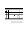
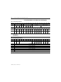
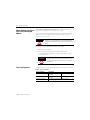
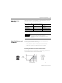
Summary of Changes
What’s Changed
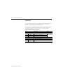
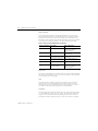
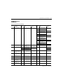
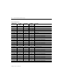
The following table lists items changed since the last printing.
Changes
See
Removed the word bit in Command 12
B-2
Removed the word bit in Command 17
B-2
Added Device-specific Commands
B-3 to B-24
To help you find new and updated information in this release of the manual,
we have included change bars as shown next to this paragraph.
1
Publication 1797-6.5.3 - March 2006
Summary of Changes
2
Notes:
Publication 1797-6.5.3 - March 2006
Table of Contents
Summary of Changes
Preface
Important User Information . . . . . . . . . . . . . . . . . . . . . . . . . . . . . . . . 1-2
What’s Changed . . . . . . . . . . . . . . . . . . . . . . . . . Summary of Changes-1
Why Read This Manual . . . . . . . . . . . . . . . . . . . . . . . . . . . . . . . . . . . .
Who Should Read This Manual. . . . . . . . . . . . . . . . . . . . . . . . . . . . . .
About the Vocabulary . . . . . . . . . . . . . . . . . . . . . . . . . . . . . . . . . . . . .
What This Manual Contains . . . . . . . . . . . . . . . . . . . . . . . . . . . . . . . .
For Additional Information. . . . . . . . . . . . . . . . . . . . . . . . . . . . . . . . .
P-1
P-1
P-1
P-1
P-2
Chapter 1
About the FLEX Ex HART Analog
Modules
What This Chapter Contains . . . . . . . . . . . . . . . . . . . . . . . . . . . . . . . . 1-1
What the FLEX Ex Analog
I/O Modules Do . . . . . . . . . . . . . . . . . . . . . . . . . . . . . . . . . . . . . . . . . 1-1
How FLEX Ex Analog Modules Communicate with Programmable
Controllers . . . . . . . . . . . . . . . . . . . . . . . . . . . . . . . . . . . . . . . . . . . . . . 1-2
Events After Cycling Power . . . . . . . . . . . . . . . . . . . . . . . . . . . . . 1-2
Physical Features of Your Analog I/O Module . . . . . . . . . . . . . . . . . 1-3
Indicators . . . . . . . . . . . . . . . . . . . . . . . . . . . . . . . . . . . . . . . . . . . . 1-3
Using Alarms on the 1797-IE8H Module. . . . . . . . . . . . . . . . . . . . . . 1-3
Data Format Alarm Example . . . . . . . . . . . . . . . . . . . . . . . . . . . . 1-4
Overrange Alarm . . . . . . . . . . . . . . . . . . . . . . . . . . . . . . . . . . . . . . 1-4
Underrange Alarm . . . . . . . . . . . . . . . . . . . . . . . . . . . . . . . . . . . . . 1-4
Remote Fault Alarm . . . . . . . . . . . . . . . . . . . . . . . . . . . . . . . . . . . 1-5
Local Fault Alarm . . . . . . . . . . . . . . . . . . . . . . . . . . . . . . . . . . . . . 1-6
How to Use the HART Capabilities . . . . . . . . . . . . . . . . . . . . . . . . . . 1-7
HART Implementation Overview . . . . . . . . . . . . . . . . . . . . . . . . . . . 1-7
HART Commands . . . . . . . . . . . . . . . . . . . . . . . . . . . . . . . . . . . . . . . . 1-8
HART Target Tags . . . . . . . . . . . . . . . . . . . . . . . . . . . . . . . . . . . . 1-9
HART Command Tags . . . . . . . . . . . . . . . . . . . . . . . . . . . . . . . . 1-10
HART Initialize Tags. . . . . . . . . . . . . . . . . . . . . . . . . . . . . . . . . . 1-11
HART Initialize Channel Tags . . . . . . . . . . . . . . . . . . . . . . . . . . 1-12
Modify Your Ladder-Logic Routine . . . . . . . . . . . . . . . . . . . . . . 1-13
Selecting the Correct Path . . . . . . . . . . . . . . . . . . . . . . . . . . . . . . . . . 1-15
Chapter Summary. . . . . . . . . . . . . . . . . . . . . . . . . . . . . . . . . . . . . . . . 1-15
Chapter 2
Understand Configurable FLEX Ex
Analog Module Features
1
What This Chapter Contains . . . . . . . . . . . . . . . . . . . . . . . . . . . . . . . .
Selecting a 1797-IE8H FLEX Ex Analog Input Module’s
Operating Features. . . . . . . . . . . . . . . . . . . . . . . . . . . . . . . . . . . . . . . .
Fault Mode . . . . . . . . . . . . . . . . . . . . . . . . . . . . . . . . . . . . . . . . . . .
Remote Transmitter Error Up or Down . . . . . . . . . . . . . . . . . . .
High Low Error Level . . . . . . . . . . . . . . . . . . . . . . . . . . . . . . . . . .
Input Filter Cutoff . . . . . . . . . . . . . . . . . . . . . . . . . . . . . . . . . . . . .
Data Format . . . . . . . . . . . . . . . . . . . . . . . . . . . . . . . . . . . . . . . . . .
Selecting a 1797-OE8H FLEX Ex Analog Output Module’s
Operating Features. . . . . . . . . . . . . . . . . . . . . . . . . . . . . . . . . . . . . . . .
2-1
2-2
2-2
2-3
2-3
2-3
2-4
2-7
Publication 1797-6.5.3 - March 2006
Table of Contents
2
Local Fault Mode . . . . . . . . . . . . . . . . . . . . . . . . . . . . . . . . . . . . . . 2-7
Latch Mode . . . . . . . . . . . . . . . . . . . . . . . . . . . . . . . . . . . . . . . . . . 2-7
Global Reset. . . . . . . . . . . . . . . . . . . . . . . . . . . . . . . . . . . . . . . . . . 2-7
Analog Digital State . . . . . . . . . . . . . . . . . . . . . . . . . . . . . . . . . . . . 2-8
Analog Fault State . . . . . . . . . . . . . . . . . . . . . . . . . . . . . . . . . . . . . 2-8
Analog Fault State Value . . . . . . . . . . . . . . . . . . . . . . . . . . . . . . . . 2-8
Digital Fault State. . . . . . . . . . . . . . . . . . . . . . . . . . . . . . . . . . . . . . 2-9
Data Format . . . . . . . . . . . . . . . . . . . . . . . . . . . . . . . . . . . . . . . . . . 2-9
Fault Alarm . . . . . . . . . . . . . . . . . . . . . . . . . . . . . . . . . . . . . . . . . 2-11
Understanding Image Table Mapping and Bit/Word Descriptions 2-12
Bit Descriptions . . . . . . . . . . . . . . . . . . . . . . . . . . . . . . . . . . . . . . 2-12
Analog Input Module (1797-IE8H) Image Table Mapping. . . . 2-13
Bit/Word Description for the Analog Input Module
(1797-IE8H). . . . . . . . . . . . . . . . . . . . . . . . . . . . . . . . . . . . . . . . . 2-14
Analog Output Module (1797-OE8H) Image Table Mapping . 2-16
1797-IE8H and -OE8H Extended Configuration Data Table . . . . 2-19
Secondary Master Enable (SME) and Primary Master
Inhibit (PMI) . . . . . . . . . . . . . . . . . . . . . . . . . . . . . . . . . . . . . . . . 2-20
Chapter Summary. . . . . . . . . . . . . . . . . . . . . . . . . . . . . . . . . . . . . . . . 2-21
Chapter 3
How to Install Your FLEX Ex
Analog Modules
Publication 1797-6.5.3 - March 2006
What This Chapter Contains . . . . . . . . . . . . . . . . . . . . . . . . . . . . . . . . 3-1
Before You Install Your Analog Module . . . . . . . . . . . . . . . . . . . . . . 3-1
Compliance to European Union Directives . . . . . . . . . . . . . . . . . . . . 3-2
EMC Directive . . . . . . . . . . . . . . . . . . . . . . . . . . . . . . . . . . . . . . . . 3-2
ATEX Directive. . . . . . . . . . . . . . . . . . . . . . . . . . . . . . . . . . . . . . . 3-2
Installation in Zone 1 . . . . . . . . . . . . . . . . . . . . . . . . . . . . . . . . . . . . . . 3-3
Installation in Zone 22 . . . . . . . . . . . . . . . . . . . . . . . . . . . . . . . . . . . . . 3-3
Electrostatic Charge . . . . . . . . . . . . . . . . . . . . . . . . . . . . . . . . . . . . . . . 3-3
Removal and Insertion Under Power . . . . . . . . . . . . . . . . . . . . . . . . . 3-4
Install the Module . . . . . . . . . . . . . . . . . . . . . . . . . . . . . . . . . . . . . . . . 3-4
Mount on a DIN Rail . . . . . . . . . . . . . . . . . . . . . . . . . . . . . . . . . . 3-5
Panel/Wall Mount . . . . . . . . . . . . . . . . . . . . . . . . . . . . . . . . . . . . 3-7
Mounting the Analog Modules on the Terminal Base Unit. . . . . 3-9
Wire the Terminal Base Units . . . . . . . . . . . . . . . . . . . . . . . . . . . . . . 3-10
Connecting Wiring to the FLEX Ex I/O Analog Modules. . . . . . . 3-11
Inputs/Outputs . . . . . . . . . . . . . . . . . . . . . . . . . . . . . . . . . . . . . . 3-11
Connections for the 1797-IE8H Module . . . . . . . . . . . . . . . . . . 3-11
Connections for the 1797-OE8H Module . . . . . . . . . . . . . . . . . 3-13
Ground the Module . . . . . . . . . . . . . . . . . . . . . . . . . . . . . . . . . . . . . . 3-14
Chapter Summary. . . . . . . . . . . . . . . . . . . . . . . . . . . . . . . . . . . . . . . . 3-15
Table of Contents
3
Publication 1797-6.5.3 - March 2006
Table of Contents
4
Chapter 4
Input, Output and Configuration
Files
for the Analog I/O Modules on the
ControlNet Network
What This Chapter Contains . . . . . . . . . . . . . . . . . . . . . . . . . . . . . . . .
Using Programming Software in Your FLEX Ex Application . . . . .
About the ControlNet Ex Adapter . . . . . . . . . . . . . . . . . . . . . . . . . . .
Communication Over the FLEX Ex Backplane. . . . . . . . . . . . . . . . .
Scheduled Data Transfer . . . . . . . . . . . . . . . . . . . . . . . . . . . . . . . .
Unscheduled Data Transfer . . . . . . . . . . . . . . . . . . . . . . . . . . . . .
Module I/O Mapping . . . . . . . . . . . . . . . . . . . . . . . . . . . . . . . . . .
I/O Structure . . . . . . . . . . . . . . . . . . . . . . . . . . . . . . . . . . . . . . . . . . . .
Adapter Status Word . . . . . . . . . . . . . . . . . . . . . . . . . . . . . . . . . . .
Fault State Data . . . . . . . . . . . . . . . . . . . . . . . . . . . . . . . . . . . . . . . . . .
Device Actions . . . . . . . . . . . . . . . . . . . . . . . . . . . . . . . . . . . . . . . . . . .
Communication Fault Behavior . . . . . . . . . . . . . . . . . . . . . . . . . .
Idle State Behavior. . . . . . . . . . . . . . . . . . . . . . . . . . . . . . . . . . . . .
Chapter Summary. . . . . . . . . . . . . . . . . . . . . . . . . . . . . . . . . . . . . . . . .
4-1
4-2
4-2
4-3
4-3
4-4
4-4
4-5
4-5
4-7
4-7
4-8
4-8
4-8
Chapter 5
Calibrate Your Module
What This Chapter Contains . . . . . . . . . . . . . . . . . . . . . . . . . . . . . . . . 5-1
When and How to Calibrate Your FLEX Ex Analog I/O Module . 5-2
Tools and Equipment . . . . . . . . . . . . . . . . . . . . . . . . . . . . . . . . . . . . . 5-2
1797-IE8H Calibration Features . . . . . . . . . . . . . . . . . . . . . . . . . . . . . 5-3
1797-IE8H Calibration Command Structure . . . . . . . . . . . . . . . . . . . 5-4
1797-IE8H Calibration Command Byte . . . . . . . . . . . . . . . . . . . . 5-5
1797-IE8H Calibration Item Byte Channel-Mask . . . . . . . . . . . . 5-8
1797-IE8H Calibration with Offset and Gain . . . . . . . . . . . . . . 5-11
1797-OE8H Calibration Features . . . . . . . . . . . . . . . . . . . . . . . . . . . 5-12
1797-OE8H Calibration Command Byte . . . . . . . . . . . . . . . . . . 5-13
1797-OE8H Calibration Item Byte Channel-Mask . . . . . . . . . . 5-19
1797-OE8H Calibration Flowchart Procedure . . . . . . . . . . . . . 5-21
Chapter 6
Apply FLEX Ex Analog I/O Modules What This Chapter Contains . . . . . . . . . . . . . . . . . . . . . . . . . . . . . . . . 6-1
Evaluate the Application . . . . . . . . . . . . . . . . . . . . . . . . . . . . . . . . . . .
Define the Area Classification . . . . . . . . . . . . . . . . . . . . . . . . . . . . . . .
Decide Classification Method . . . . . . . . . . . . . . . . . . . . . . . . . . . .
Determine Hazard . . . . . . . . . . . . . . . . . . . . . . . . . . . . . . . . . . . . .
Determine Temperature Rating . . . . . . . . . . . . . . . . . . . . . . . . . .
Select Protection Method(s) . . . . . . . . . . . . . . . . . . . . . . . . . . . . . . . .
Match Field Devices and I/O Modules . . . . . . . . . . . . . . . . . . . . . . .
P/I Analog Transmitter Functional and IS Parameters. . . . . . . .
1797-IE8H Functional and IS Parameters . . . . . . . . . . . . . . . . . .
Loop Functionality Verification . . . . . . . . . . . . . . . . . . . . . . . . . .
Intrinsic Safety Entity Verification . . . . . . . . . . . . . . . . . . . . . . . .
I/O . . . . . . . . . . . . . . . . . . . . . . . . . . . . . . . . . . . . . . . . . . . . . . . . .
Publication 1797-6.5.3 - March 2006
6-1
6-2
6-2
6-2
6-2
6-3
6-3
6-3
6-4
6-4
6-6
6-7
Table of Contents
5
Optimize Power Distribution . . . . . . . . . . . . . . . . . . . . . . . . . . . . . . . 6-7
Assigning Power Supplies . . . . . . . . . . . . . . . . . . . . . . . . . . . . . . . 6-8
Power Supply Considerations . . . . . . . . . . . . . . . . . . . . . . . . . . . 6-10
Chapter Summary. . . . . . . . . . . . . . . . . . . . . . . . . . . . . . . . . . . . . . . . 6-10
Chapter 7
Troubleshoot the FLEX Ex
Analog I/O Modules
What This Chapter Contains . . . . . . . . . . . . . . . . . . . . . . . . . . . . . . . .
Status Indicators . . . . . . . . . . . . . . . . . . . . . . . . . . . . . . . . . . . . . . . . . .
1797-IE8H Module . . . . . . . . . . . . . . . . . . . . . . . . . . . . . . . . . . . .
1797-OE8H Module . . . . . . . . . . . . . . . . . . . . . . . . . . . . . . . . . . .
Repair . . . . . . . . . . . . . . . . . . . . . . . . . . . . . . . . . . . . . . . . . . . . . . . . . .
Chapter Summary. . . . . . . . . . . . . . . . . . . . . . . . . . . . . . . . . . . . . . . . .
7-1
7-1
7-1
7-2
7-3
7-3
Appendix A
Specifications
1797-IE8H Input Module . . . . . . . . . . . . . . . . . . . . . . . . . . . . . . . . . A-1
Specifications . . . . . . . . . . . . . . . . . . . . . . . . . . . . . . . . . . . . . . . . A-1
1797-IE8H CE, CENELEC I/O Entity Parameters. . . . . . . . . A-3
1797-IE8H UL, C-UL I/O Entity Parameters. . . . . . . . . . . . . . A-4
1797-IE8H FM I/O Entity Parameters . . . . . . . . . . . . . . . . . . . A-7
1797-OE8H Output Module . . . . . . . . . . . . . . . . . . . . . . . . . . . . . . A-10
Specifications . . . . . . . . . . . . . . . . . . . . . . . . . . . . . . . . . . . . . . . A-10
1797-OE8H CENELEC I/O Entity Parameters . . . . . . . . . . A-11
Appendix B
FLEX Ex HART Module Commands What This Appendix Contains . . . . . . . . . . . . . . . . . . . . . . . . . . . . . . B-1
Protocol Overview . . . . . . . . . . . . . . . . . . . . . . . . . . . . . . . . . . . . . . . . B-1
Universal Commands . . . . . . . . . . . . . . . . . . . . . . . . . . . . . . . . . . . . . . B-2
Common Practice Commands. . . . . . . . . . . . . . . . . . . . . . . . . . . . . . . B-3
Device-specific Commands . . . . . . . . . . . . . . . . . . . . . . . . . . . . . . . . . B-3
Command 128 . . . . . . . . . . . . . . . . . . . . . . . . . . . . . . . . . . . . . . . . B-3
Command 129 . . . . . . . . . . . . . . . . . . . . . . . . . . . . . . . . . . . . . . . . B-4
Command 130 . . . . . . . . . . . . . . . . . . . . . . . . . . . . . . . . . . . . . . . . B-6
Command 131 . . . . . . . . . . . . . . . . . . . . . . . . . . . . . . . . . . . . . . . . B-7
Command 132 . . . . . . . . . . . . . . . . . . . . . . . . . . . . . . . . . . . . . . . . B-8
Command 133 . . . . . . . . . . . . . . . . . . . . . . . . . . . . . . . . . . . . . . . . B-8
Command 134 . . . . . . . . . . . . . . . . . . . . . . . . . . . . . . . . . . . . . . . . B-9
Command 135 . . . . . . . . . . . . . . . . . . . . . . . . . . . . . . . . . . . . . . . B-10
Command 136 . . . . . . . . . . . . . . . . . . . . . . . . . . . . . . . . . . . . . . . B-11
Command 137 . . . . . . . . . . . . . . . . . . . . . . . . . . . . . . . . . . . . . . . B-12
Command 138 . . . . . . . . . . . . . . . . . . . . . . . . . . . . . . . . . . . . . . . B-13
Command 139 . . . . . . . . . . . . . . . . . . . . . . . . . . . . . . . . . . . . . . . B-14
Command 140 . . . . . . . . . . . . . . . . . . . . . . . . . . . . . . . . . . . . . . . B-15
Command 141 . . . . . . . . . . . . . . . . . . . . . . . . . . . . . . . . . . . . . . . B-16
Command 143 . . . . . . . . . . . . . . . . . . . . . . . . . . . . . . . . . . . . . . . B-17
Command 144 . . . . . . . . . . . . . . . . . . . . . . . . . . . . . . . . . . . . . . . B-17
Publication 1797-6.5.3 - March 2006
Table of Contents
6
Command 145 . . . . . . . . . . . . . . . . . . . . . . . . . . . . . . . . . . . . . . .
Command 146 . . . . . . . . . . . . . . . . . . . . . . . . . . . . . . . . . . . . . . .
Command 147 . . . . . . . . . . . . . . . . . . . . . . . . . . . . . . . . . . . . . . .
Command 148 . . . . . . . . . . . . . . . . . . . . . . . . . . . . . . . . . . . . . . .
Command 149 . . . . . . . . . . . . . . . . . . . . . . . . . . . . . . . . . . . . . . .
Command 152 . . . . . . . . . . . . . . . . . . . . . . . . . . . . . . . . . . . . . . .
Command 154 . . . . . . . . . . . . . . . . . . . . . . . . . . . . . . . . . . . . . . .
Command 158 . . . . . . . . . . . . . . . . . . . . . . . . . . . . . . . . . . . . . . .
Command 159 . . . . . . . . . . . . . . . . . . . . . . . . . . . . . . . . . . . . . . .
Command 164 . . . . . . . . . . . . . . . . . . . . . . . . . . . . . . . . . . . . . . .
B-18
B-19
B-20
B-20
B-21
B-21
B-22
B-23
B-24
B-24
Appendix C
Additional HART Protocol
Information
What This Appendix Contains . . . . . . . . . . . . . . . . . . . . . . . . . . . . . . C-1
Message Structure. . . . . . . . . . . . . . . . . . . . . . . . . . . . . . . . . . . . . . . . . C-1
Master-slave Operation . . . . . . . . . . . . . . . . . . . . . . . . . . . . . . . . . C-1
Multiple Master Operation . . . . . . . . . . . . . . . . . . . . . . . . . . . . . . C-1
Transaction Procedure. . . . . . . . . . . . . . . . . . . . . . . . . . . . . . . . . . C-2
Burst Mode (not supported) . . . . . . . . . . . . . . . . . . . . . . . . . . . . . C-2
Universal Commands . . . . . . . . . . . . . . . . . . . . . . . . . . . . . . . . . . . . . . C-7
Common Practice Commands. . . . . . . . . . . . . . . . . . . . . . . . . . . . . . . C-9
Appendix D
Configure the 1797-OE8H Module What This Appendix Contains . . . . . . . . . . . . . . . . . . . . . . . . . . . . . D-1
in RSLogix 5000 Software Over the Background Information . . . . . . . . . . . . . . . . . . . . . . . . . . . . . . . . . . D-1
Configuration . . . . . . . . . . . . . . . . . . . . . . . . . . . . . . . . . . . . . . . . . . . D-2
ControlNet Network
Analog Fault State . . . . . . . . . . . . . . . . . . . . . . . . . . . . . . . . . . . . D-4
Fault Mode . . . . . . . . . . . . . . . . . . . . . . . . . . . . . . . . . . . . . . . . . . D-4
Local Fault Mode . . . . . . . . . . . . . . . . . . . . . . . . . . . . . . . . . . . . . D-4
Latch Retry Mode . . . . . . . . . . . . . . . . . . . . . . . . . . . . . . . . . . . . D-5
Analog/Digital Mode . . . . . . . . . . . . . . . . . . . . . . . . . . . . . . . . . D-5
Digital Fault State. . . . . . . . . . . . . . . . . . . . . . . . . . . . . . . . . . . . . D-6
Analog Fault State Values . . . . . . . . . . . . . . . . . . . . . . . . . . . . . . D-6
Output. . . . . . . . . . . . . . . . . . . . . . . . . . . . . . . . . . . . . . . . . . . . . . . . . D-7
Digital Output Data. . . . . . . . . . . . . . . . . . . . . . . . . . . . . . . . . . . D-7
Global Reset Bit . . . . . . . . . . . . . . . . . . . . . . . . . . . . . . . . . . . . . . D-7
Analog Output Data . . . . . . . . . . . . . . . . . . . . . . . . . . . . . . . . . . D-7
Input . . . . . . . . . . . . . . . . . . . . . . . . . . . . . . . . . . . . . . . . . . . . . . . . . . D-8
Diagnostic Status Data . . . . . . . . . . . . . . . . . . . . . . . . . . . . . . . . D-8
HART Rebuild Bit . . . . . . . . . . . . . . . . . . . . . . . . . . . . . . . . . . . . D-8
Fault Alarm . . . . . . . . . . . . . . . . . . . . . . . . . . . . . . . . . . . . . . . . . D-8
HART Failure . . . . . . . . . . . . . . . . . . . . . . . . . . . . . . . . . . . . . . . D-9
HART Readback . . . . . . . . . . . . . . . . . . . . . . . . . . . . . . . . . . . . . D-9
HART Communication . . . . . . . . . . . . . . . . . . . . . . . . . . . . . . . . D-9
HART Transmitter . . . . . . . . . . . . . . . . . . . . . . . . . . . . . . . . . . D-10
Publication 1797-6.5.3 - March 2006
Table of Contents
7
Appendix E
Configure the 1797-IE8H Module in What This Appendix Contains . . . . . . . . . . . . . . . . . . . . . . . . . . . . . . E-1
Background Information . . . . . . . . . . . . . . . . . . . . . . . . . . . . . . . . . . . E-1
RSLogix 5000 Software Over the
Configuration . . . . . . . . . . . . . . . . . . . . . . . . . . . . . . . . . . . . . . . . . . . . E-2
ControlNet Network
Fault Mode . . . . . . . . . . . . . . . . . . . . . . . . . . . . . . . . . . . . . . . . . . . E-2
Data Format Control . . . . . . . . . . . . . . . . . . . . . . . . . . . . . . . . . . . E-2
Filter Cutoff . . . . . . . . . . . . . . . . . . . . . . . . . . . . . . . . . . . . . . . . . . E-4
Up/Down Bit. . . . . . . . . . . . . . . . . . . . . . . . . . . . . . . . . . . . . . . . . E-5
High and Low Error Level . . . . . . . . . . . . . . . . . . . . . . . . . . . . . . E-5
Square Root Threshold . . . . . . . . . . . . . . . . . . . . . . . . . . . . . . . . . E-7
Input . . . . . . . . . . . . . . . . . . . . . . . . . . . . . . . . . . . . . . . . . . . . . . . . . . . E-7
Analog Input Data . . . . . . . . . . . . . . . . . . . . . . . . . . . . . . . . . . . . . E-7
Underrange Alarm . . . . . . . . . . . . . . . . . . . . . . . . . . . . . . . . . . . . . E-7
Overrange Alarm . . . . . . . . . . . . . . . . . . . . . . . . . . . . . . . . . . . . . . E-8
Local Fault . . . . . . . . . . . . . . . . . . . . . . . . . . . . . . . . . . . . . . . . . . . E-8
Remote Fault . . . . . . . . . . . . . . . . . . . . . . . . . . . . . . . . . . . . . . . . . E-8
Diagnostic Status . . . . . . . . . . . . . . . . . . . . . . . . . . . . . . . . . . . . . . E-9
Appendix F
FLEX Ex HART Modules Network
Messaging
What This Appendix Contains . . . . . . . . . . . . . . . . . . . . . . . . . . . . . .
Communication . . . . . . . . . . . . . . . . . . . . . . . . . . . . . . . . . . . . . . . . . .
Differences Between Attributes and Assembly Indexes . . . . . . . . . .
HART Frame Enhancements . . . . . . . . . . . . . . . . . . . . . . . . . . . . . . .
F-1
F-1
F-3
F-6
Index
Rockwell Automation Support . . . . . . . . . . . . . . . . . . . . . . . . . . . . . . 1-4
Installation Assistance . . . . . . . . . . . . . . . . . . . . . . . . . . . . . . . . . . 1-4
New Product Satisfaction Return . . . . . . . . . . . . . . . . . . . . . . . . . 1-4
Publication 1797-6.5.3 - March 2006
Table of Contents
8
Publication 1797-6.5.3 - March 2006
Preface
Why Read This Manual
This manual shows you how to use your FLEX Ex analog modules with the
ControlNet Ex products and ControlNet network. The manual helps you
install, program, and troubleshoot your module.
Who Should Read This
Manual
You must be able to program and operate a ControlNet Ex product and
ControlNet network to make efficient use of a FLEX Ex module.
About the Vocabulary
In this manual, we refer to the:
• 1797-IE8H as the input module
• 1797-OE8H as the output module
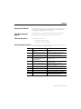
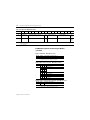
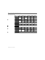
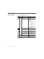
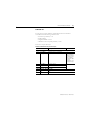
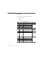
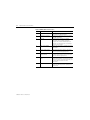
What This Manual Contains
Chapter
Title
Contents
1
About the FLEX Ex HART Analog
Modules
Describes module functionality and physical
features
2
Understand Configurable FLEX Ex
Analog Module Features
Describes configurable module features and
configuration bits
3
How to Install Your FLEX Ex Analog
Modules
How to install and wire the modules
4
Input, Output and Configuration Files
for the Analog I/O Modules on the
ControlNet Network
Describes how to use these I/O modules over the
ControlNet network
5
Calibrate Your Module
Lists the tools needed, and the methods used to
calibrate the module
6
Apply FLEX Ex Analog I/O Modules
Describes how FLEX Ex is different from
traditional control systems
7
Troubleshoot the FLEX Ex Analog I/O
Modules
How to use the indicators to troubleshoot your
module
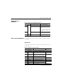
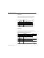
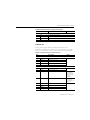
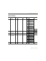
Appendix Title
Contents
A
Outlines module specifications and accuracy
B
Explains how to program the analog modules
C
1
The following chart lists each chapter with its corresponding title and a brief
overview of the topics covered in that chapter.
Additional HART Protocol Information Discusses the HART protocol and provides
references for additional information.
Publication 1797-6.5.3 - January 2006
Preface
2
D
Configure the 1797-OE8H Module in
RSLogix 5000 Software Over the
ControlNet Network
Provides the information necessary to configure
the 1797-OE8H analog output module.
E
Configure the 1797-IE8H Module in
RSLogix 5000 Software Over the
ControlNet Network
Provides the information necessary to configure
the 1797-IE8H analog input module.
F
FLEX Ex HART Modules Network
Messaging
Discusses how to communicate with the HART
modules via the MSG or CIO instruction,
differences between attributes and assembly
indexes, and enhancements to the HART frame.
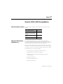
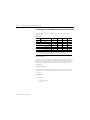
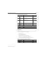
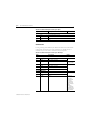
For additional information on FLEX Ex systems and modules, refer to the
following documents.
For Additional Information
Publications
Catalog
Number
Publication 1797-6.5.3 - January 2006
Description
Installation
Instructions
User Manual
1797 Series
FLEX Ex Selection Guide
1794-SG002
1797 Series
ControlNet Ex System Cable Guide
1797-TB3
FLEX Ex Terminal Base
1797-TB3S
FLEX Ex Spring Clamp Terminal Base
1797-OE8H
FLEX Ex HART 8 Output Analog Module
1797-5.3
1797-6.5.3
1797-IRT8
FLEX Ex RTD/Thermocouple/mV Module
1797-5.4
1797-6.5.2
1797-IE8H
FLEX Ex HART 8 Input Analog Module
1797-5.5
1797-6.5.3
1797-OB4D
4 Output Module
1797-5.6
1797-IBN16
FLEX Ex NAMUR Digital Input Module
1797-5.7
1797-PS2E2
FLEX Ex Power Supply
1797-5.8
1797-IJ2
2 Frequency Input Module
1797-5.9
1797-PS2N2
FLEX Ex Power Supply
1797-5.12
1797-BIC
FLEX Ex Bus Isolator
1797-CEC
FLEX Ex Flexbus Connector
1797-ACNR15
ControlNet Ex Adapter
1797-5.14
1797-RPA, -RPFM
Fiber Hub
1797-5.15
1797-TPR, -TPRS,
-TPYR, -TPYS
FLEX Ex Taps
1797-5.18
1797-CE1S, -CE3S,
-CEFTN, -CEFTE
Interconnect Cables
1797-EXMK
Marker Kit
1797-5.23
1797-PS1E
FLEX Ex Power Supply
1797-5.33
1797-PS1N
FLEX Ex Power Supply
1797-5.34
1797-BCNR
FLEX Ex Redundant ControlNet Barrier Module
1797-5.35
1797-6.2.1
1797-5.1
1797-6.5.4
1797-5.13
1797-5.20
1797-6.2.1
Chapter
1
About the FLEX Ex HART Analog Modules
What This Chapter Contains
What the FLEX Ex Analog
I/O Modules Do
Read this chapter to familiarize yourself with the input and output analog
modules.
For
See
What the FLEX Ex Analog I/O
Modules Do
1-1
How FLEX Ex Analog Modules
Communicate with Programmable
Controllers
1-2
Physical Features of Your Analog I/O
Module
1-3
Chapter Summary
1-15
The 1797-IE8H module accepts up to 8 analog inputs. The inputs are
non-isolated and will accept current in either of the following two ranges: 4 to
20 mA or 0 to 20mA. The default input range is 0 to 20 mA. The inputs have
both fixed hardware filters and selectable firmware digital filters.
Similarly, the 1797-OE8H module provides as many as eight analog outputs.
The outputs are nonisolated and will provide current in either of the following
two ranges: 4 to 20 mA or 0 to 20 mA. The default output range is 0 to 20 mA.
Each module offers host of features including:
• Local microprocessor intelligence for advanced features
• Full functionality without switches or jumpers
• Multiple data ranges that can be independently programmed
in channel groups
• Lead breakage detection
• Overrange/underrange alarms
• Remote transmitter alarm
1
Publication 1797-6.5.3 - March 2006
1-2
About the FLEX Ex HART Analog Modules
How FLEX Ex Analog
Modules Communicate
with Programmable
Controllers
FLEX Ex analog I/O modules provide best utility when used with ControlNet
Ex products on the ControlNet network. Data connections are established
between the I/O module and an Allen-Bradley programmable controller to
transfer information between the two at a scheduled rate.
Input module information is then automatically made available in the PLC
data table through the data connection. Reciprocally, output data information
determined by the PLC program is also automatically transferred from the
PLC data table to the output module through the data connection.
In addition, when the data connection is originally established, configuration
information for the module is automatically transferred to it via the network.
Events After Cycling Power
You must apply intrinsically safe +/-V power to your FLEX Ex analog I/O
modules. The following sequence of events occurs after power has initially
been applied to your module:
• The module begins an internal diagnostic check. The channel 0 LED
indicator turns ON to indicate the check has begun. The indicator turns
OFF when the check is finished.
• After the diagnostic check, module configuration information, selected
by the user and downloaded over the network, is applied by the module.
For more information on configuration options, see Chapter 2.
• Following the module configuration download for the 1797-IE8H
module, the module begins producing runtime data for the PLC.
• Following the module configuration download for the 1797-OE8H
module, the module applies configuration data to output channels.
• If any diagnostics or alarms are generated during normal module
operation, the data is returned to the PLC controller.
Publication 1797-6.5.3 - March 2006
About the FLEX Ex HART Analog Modules
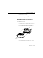
Physical Features of Your
Analog I/O Module
1-3
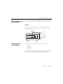
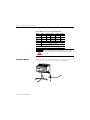
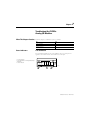
The module label identifies the keyswitch position, wiring and module type.
Use the removable label to note individual designations per your application.
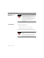
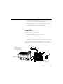
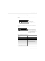
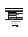
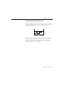
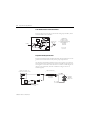
Indicators
Indicators are provided to identify input or output fault conditions, and to
show when power is applied to the module. For example, the 1797-IE8H
module is shown below.
1797-IE8H
Module Type
Removable Label
Ex
1797-IE8
8 CHANNEL ANALOG INPUT
3
IN0
IN1
IN2
IN3
IN4
IN5
Input Designators
Using Alarms on the
1797-IE8H Module
IN6
IN7
PWR
Keyswitch Position
Indicator (#3)
Power On Indicator
40070
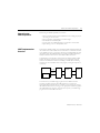
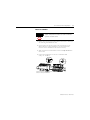
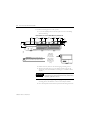
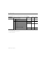
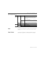
The 1797-IE8H FLEX Ex module is capable of generating four alarms:
•
•
•
•
Underrange
Overrange
Remote Fault
Local Fault
These alarm conditions are described in general terms and as they relate to bits
on the FLEX Ex I/O module on the following pages. The following graphic
shows at what values these alarms are generated for Data Format 4.
Publication 1797-6.5.3 - March 2006
1-4
About the FLEX Ex HART Analog Modules
Data Format Alarm Example
In this example, the normal active data range is 4 to 20 mA. The alarms are
generated in three overlapping bands.
PHYSICAL INPUT SIGNAL RANGE
0 mA
4 mA
20 mA
Underrange
22 mA
Overrange
Remote Fault
Remote Fault
Local
Fault
-25.00% -12.50%
Programmable
in 20 0.1 mA
Steps by Error
Level 0.1 mA
Steps
Parameter
Local
Fault
0.00%
100.00%
Remote Transmitter Error
Up/Down Parameter
Determines Which of These
is Active
Programmable
in 20 0.1 mA
Steps by Error
Level 0.1 mA
Steps
Parameter
112.50%
41666
Overrange Alarm
The Overrange alarm notifies you when module input is overrange. When the
input signal exceeds 100% (20 mA), an Overrange Alarm is generated.
This alarm stays active at any value above 100% of range and is always enabled
by the module.
Underrange Alarm
The Underrange alarm works in a fashion converse to the overrange. This
feature notifies you when the input signal falls underrange. If the input signal
falls below 0% (4 mA), an Underrange Alarm is generated.
This alarm stays active at any value below 0% of range and is always enabled by
the module.
Publication 1797-6.5.3 - March 2006
About the FLEX Ex HART Analog Modules
1-5
Remote Fault Alarm
The Remote Fault Alarm is primarily intended for use with remote transmitter
loops.
For example, the remote transmitter may be measuring temperature and
converting it to a standard mA signal. In such a loop, though, the input module
cannot determine the state of the loop on the far side of the transmitter.
However, the remote transmitter may be capable of diagnosing a problem in
the remote loop and signal the input module local loop with a preprogrammed
out of range (high or low) value.
The Remote Fault Alarm allows the 1797-IE8H module to work with
transmitters like the one just described. You must use the Remote Transmitter
Error Up or Down feature, see page 2-3, to configure your application for
Remote Fault notification.
For example, you must determine if you want a remote fault to cause
high out of range values or low out of range values to be returned to
the controller.
IMPORTANT
Once the alarm is issued, it remains active as long as the input
signal value remains above the programmed value.
Use Remote Fault Alarm to Determine High High or Low Low Alarm Levels
If you do not have a remote transmitter in your loop, this alarm can also be
used to program a high high or low low alarm level between the levels which
actuate the overrange or underrange alarms and the high or low local fault
alarms.
IMPORTANT
When establishing high high or low low alarms, you can only
select one side (high or low). You must use the Remote
Transmitter Error Up or Down feature in conjunction with this
alarm.
Publication 1797-6.5.3 - March 2006
1-6
About the FLEX Ex HART Analog Modules
Program the Remote Fault Alarm
For the Remote Fault alarm, you must program the threshold in 0.1 mA steps
at any level on the high or low end of input signal range. The Remote Fault
alarm activates if your I/O module receives input signal values of:
• 100.63% (20.1 mA) to 111.88% (21.9 mA) on the high end of input
signal range
or
• -0.63% (3.9 mA) to -11.88% (2.1 mA) on the low end of input
signal range
IMPORTANT
This alarm is only active for one band, either on the high side of
normal operation or the low side.The Remote Transmitter Error
Up/Down parameter determines which side is active. See page
2-3 for a description of the Remote Transmitter Error Up/Down
feature.
Local Fault Alarm
The Local Fault alarm notifies you when the loop to the transmitter or field
device, if no transmitter is used, is open or shorted.
IMPORTANT
Once the alarm is issued, it remains active as long as the input
signal value remains in the programmed range.
• 112.50% (22 mA) or higher on the high end of input signal range - This
value indicates a short in the loop.
or
• -12.50% (2 mA) or lower on the low end of input signal range
- This value indicates an open wire condition in the loop.
The Remote Fault and Local Fault alarms are issued with the same bit whether
the cause is an under or overrange. Monitor the Overrange and Underrange
bits in your programming software to determine if the problem is a high
current or low current.
Publication 1797-6.5.3 - March 2006
About the FLEX Ex HART Analog Modules
1-7
How to Use the
HART Capabilities
Before using the HART capabilities, be sure that:
HART Implementation
Overview
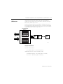
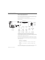
The FLEX Ex HART modules act as intelligent HART multiplexers. Basically,
the module learns which HART devices are attached to its channels and then
routes HART messages, as appropriate, between the HART field devices and
the Flexbus. Since the HART modules act as intelligent HART multiplexers,
HART commands can be issued to the HART modules themselves.
• the I/O module and the associated field device are working properly in
the analog 4 to 20 mA mode.
• the I/O module is configured for 4 to 20 mA range.
• the field device is HART capable.
• no more than one HART field device is connected to each channel.
• input filtering is set to a valid (defined) value.
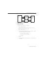
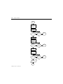
Communication on the Flexbus occurs between the adapter and the HART
module. The adapter converts these messages to the appropriate network
format for communication with the controlling controller. The controlling
controller gets its command from the user program, storing the responses in
its memory.
Controller
Adapter
FLEX Ex HART
I/O Module
Command
For Example,
ControlNet
User Program
Flexbus
HART
Field Device
4 to 20 mA
Response
In its basic form, your ladder-logic program issues an MSG instruction
containing a HART command. The MSG instruction is routed to the
appropriate adapter and FLEX Ex I/O module. Upon receiving the message,
the HART module routes the message to the appropriate channel and gathers
the HART field device response. To retrieve this response, your ladder-logic
program issues another MSG instruction.
Publication 1797-6.5.3 - March 2006
1-8
About the FLEX Ex HART Analog Modules
HART Commands
Building a usable HART command for the MSG instruction involves an
understanding of how to create a standard HART command plus the
additional knowledge of how to pack the message into a ControlNet frame. To
simplify this process, you can download the ladder-logic program discussed
here at http://www.ab.com/io. This ladder-logic program consists of a main
program and several subroutines. Modify the main program to meet your
application needs.
The first routine is HART_initialize. Use this routine after a power cycle or
reset to enable HART functionality on a specific FLEX Ex HART module and
to rebuild the associated HART loops to its field device(s). Once a FLEX Ex
HART module is initialized, it remembers the HART addresses of the field
devices and associates them to their corresponding analog channel. This
routine calls the Get_Status_with_retry subroutine to poll an answer from the
target I/O module.
The second routine is Send_Hart_SF. This routine accepts a generic HART
message to a specific I/O channel and returns a generic HART response. This
routine calls the Get_Message_with_retry subroutine to poll a response from
the target I/O module.
The third routine is Purge. If a communication error is found, this routine is
called to empty the HART buffer in the FLEX Ex HART I/O module.
Use the remaining routines to execute specific HART commands. Each
routine is dedicated to its associated HART command. For example, the
HART_CMD_3 issues a HART command 3 to the specified target device.
To issue a HART command, after the FLEX Ex HART I/O module is
initialized, fill the tag HART_Target with the associated information to
uniquely describe the path to the target. If the HART command requires
information to be send to the target device, then fill a second tag with the
appropriate information.
For example, to send a HART command 3, fill the HART_Target tag. As this
is a HART read command, no other information is necessary. To send a
HART command 35, fill the HART_Target tag. As this is a HART write
command, also fill the CMD35_cmd tag with appropriate data.
Publication 1797-6.5.3 - March 2006
About the FLEX Ex HART Analog Modules
1-9
HART Target Tags
The HART_Target tag consists of four members:
• Path — HART_Target.Path
The Path specifies the direction the message follows to get to the
desired target node. The data type is string.
• Slot — HART_Target.Slot
The Slot indicates the specific place where the I/O module is attached
to the FLEX Ex adapter. The data type is SINT.
1 = the closest module to the adapter
8 = the module farthest from the adapter
0 = the adapter
• Channel
The Channel indicates which analog channel, 0 to 7, is desired. The data
type is SINT.
• Host_Group
The FLEX Ex HART modules have two message-access ports into
them allowing two systems to gather information from the module
concurrently. The data type is SINT.
The HART_Groups are numbered either 1 or 2. If there are no other
systems accessing the FLEX Ex Hart I/O module, that is, an asset
management system, then select the first HART_Group by setting this
value to 1.
IMPORTANT
If multiple owners access or control the same FLEX Ex HART I/O
module and field device, they must maintain identical
configurations.
Publication 1797-6.5.3 - March 2006
1-10
About the FLEX Ex HART Analog Modules
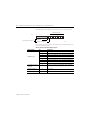
HART Command Tags
The response from the HART command routines is located in their associated
reply tags:
• CMDx_Status (x is the specific command)
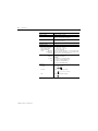
Table 1.1 CMDx_Status Tags
Tag Name
Description
Data Type
CMDx_Status.Started
Indicates when the command is in
process
BOOL
CMDx_Status.Done
Indicates when the command has
completed without error
CMDx_Status.Error
Indicates when the command has
completed with error
CMDx_Status.Error_Code
If the CMDx_Status.Error bit is set,
the associated error code is placed
here
CMDx_Status.Cmd_Performed
If the CMDx_Status.Done bit is set,
the tag containing the HART
command performed is placed here
INT
• CMDx_Reply (x is the specific command)
This tag is only returned when the specific HART command has data in
its reply. The CMDx_Reply tag contains the HART response
reformatted to their associated data type.
Table 1.2 CMD3_Reply Tags Example
Publication 1797-6.5.3 - March 2006
Tag Name
Description
Data Type
CMD3_Reply.Current_mA
The measured current value
REAL
CMD3_Reply.PV_Units_Code
The units code for the primary value INT
CMD3_Reply.Primary_Value
The primary value
REAL
CMD3_Reply.SV_Units_Code
The units code for the secondary
value
INT
CMD3_Reply.Secondary_Value
The secondary value
REAL
CMD3_Reply.TV_Units_Code
The units code for the third value
INT
CMD3_Reply.Third_Value
The third value
REAL
CMD3_Reply.FV_Units_Code
The units code for the fourth value
INT
CMD3_Reply.Fourth_Value
The fourth value
REAL
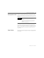
About the FLEX Ex HART Analog Modules
Your
Ladder-logic
Program
HART_Target
CMDx_cmd
Status
CMDx_reply
HART_CMD_x
Convert CMD
Data Type to
Generic HART
Frame
1-11
Generic_HART
Send_HART_SF
Command Frame
Send Message
to Target and
Poll for a
Generic_HART Response
Reply Frame
Convert Generic
HART Reply
Status
Frame to Specific
Reply Data Type
HART Initialize Tags
The HART_Target tag consists of four members:
• Path — HART_Target.Path
The Path specifies the direction the message follows to get to the
desired target node. The data type is string.
• Slot — HART_Target.Slot
The Slot indicates the specific place where the I/O module is attached
to the FLEX Ex adapter. The data type is SINT.
1 = the closest module to the adapter
8 = the module farthest from the adapter
0 = the adapter
• Channel
The Channel indicates which analog channel, 0 to 7, is desired. The data
type is SINT.
Publication 1797-6.5.3 - March 2006
1-12
About the FLEX Ex HART Analog Modules
• Host_Group
The FLEX Ex HART modules have two message-access ports into
them allowing two systems to gather information from the module
concurrently.
The HART_Groups are numbered either 1 or 2. If there are no other
systems accessing the FLEX Ex Hart I/O module, that is, an asset
management system, then select the first HART_Group by setting this
value to 1. The data type is SINT.
IMPORTANT
If multiple owners access or control the same FLEX Ex HART I/O
module and field device, they must maintain identical
configurations.
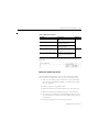
HART Initialize Channel Tags
The channel member of the HART_Target tag is a decimal number that
indicates which channel is the target. The channels’ member of the
HART_initialize tag consists of eight one bit flags.
Ch 7 Ch 6 Ch 5 Ch 4 Ch 3 Ch 2 Ch 1 Ch 0
0 = Search for a HART Field Device on the
Associated Channel
1 = Disables Searching for a HART Field
Device on the Associated Channel
IMPORTANT
Publication 1797-6.5.3 - March 2006
To make the HART_initialize routine run effectively, only enable
channels with active HART field devices.
About the FLEX Ex HART Analog Modules
1-13
Table 1.3 HART_Init_Status Tags
Tag Name
Description
Data Type
HART_Init_Status.Started
Indicates when the command is in
process
BOOL
HART_Init_Status.Done
Indicates when the command has
completed without error
HART_Init_Status.Error
Indicates when the command has
completed with error
HART_Init_Status.Error_Code
If the CMDx_Status.Error bit is set,
the associated error code is placed
here
HART_Init_Status.HART_Channels_
Found
If the CMDx_Status.Done bit is set,
the tag containing the list of
channels with active HART field
devices
INT
When these tags are initialized, a JSR to the HART_initialize routine is
performed.
Modify Your Ladder-Logic Routine
With this background information, it is now time to modify the routine to
meet the needs of your application. To do so, perform the following steps:
1. Make sure your wiring is correct and make note of your node address,
the slot location of the FLEX Ex HART I/O module and the channel
with your field device.
2. Load the program into Logix5000 software.
3. Modify the members of the HART_initialize tag to match your setup.
4. Modify the members of the HART_Target tag to match your setup.
5. If you plan to use a HART write command, which requires data to be
sent to the field device, modify the associated CMDx_cmd tag with the
associated data.
6. Download the program to the ControlLogix controller.
Publication 1797-6.5.3 - March 2006
1-14
About the FLEX Ex HART Analog Modules
7. Place the controller into RUN mode.
This assumes you will re-write the Main Routine to meet your
application.
8. Refer to the following list of error codes if an error is returned from one
of the following routines:
Table 1.4 HART_Initialize Routine
Error Code
Description
-1
Could not enable HART LEDs
-2
Could not rebuild HART loops
-3
Routine timed out
-4
Could not get status from Rebuild HART
Loops command
Table 1.5 HART_CMD_x Routine
Error Code
Description
-1
Invalid slot number
-2
Invalid expected data size
-3
Invalid Host Group number
-4
Could not get a response
Once you have modified your ladder-logic routine, the ladder logic will now
call the HART_initialize routine. The yellow LEDs on the associated channels
of the selected FLEX Ex HART module will start to flash. This indicates that
the module has received the command and is in the process of searching for
HART field devices on the associated channels. Upon successful completion
of the HART_initialize routine, the HART_Init_Status_Done flag is set. At
this point, the ladder logic will examine the contents of the HART_Cmd tag
and attempt to issue the HART command associated with the decimal number
contained in this tag. Any HART replies are placed in their associated
CMDx_reply tag. To issue a different command, change the value of the
HART_Cmd tag to match the desired HART Command.
Publication 1797-6.5.3 - March 2006
About the FLEX Ex HART Analog Modules
Selecting the Correct Path
1-15
The Path is a string that specifies the direction the message follows to get to a
desired node. The MSG instruction requires a specific format for the string,
consisting of a number sequence with each number separated by a $ sign. The
message sequence is performed in sequential order from the perspective of the
controller.
EXAMPLE
(1)
A path of $01$03$02$05 is interpreted as:
$01 = Go out the backplane port of the 1756
controller
$03 = Go to the module in slot 3 of the 1756 chassis(1)
$02 = Go out the front communications port of the
module
$05 = Go to node address 5
Assume that a 1756-CNB is in slot 3.
If you are using a ControlLogix system, the numbers $01 and the $02 will
usually be in these sequence locations. The $03 may vary depending on the slot
location of your network module. The $05 will vary according to your target
address. If you need to bridge to other networks, then additional numbers will
be needed in the sequence. For more details on this method, search in the
Logix5000 Help.
Chapter Summary
In this chapter, you learned about FLEX Ex analog I/O modules and HART
module capabilities. Move on to Chapter 2 to learn about configurable features
on your module.
Publication 1797-6.5.3 - March 2006
1-16
About the FLEX Ex HART Analog Modules
Notes:
Publication 1797-6.5.3 - March 2006
Chapter
2
Understand Configurable FLEX Ex Analog
Module Features
What This Chapter Contains
Read this chapter to familiarize yourself with configurable features on the
input and output analog modules.
For
See
Selecting a 1797-IE8H FLEX Ex Analog
Input Module’s Operating Features
2-2
Selecting a 1797-OE8H FLEX Ex Analog
Output Module’s Operating Features
2-7
Understanding Image Table Mapping and
Bit/Word Descriptions
2-12
Instance: Slot number (range from 1 to 8
with 1 being the I/O module closest to the
adapter
2-19
HART configurable features described in this chapter include:
Table 2.1 Analog/Digital Configurable Features on the FLEX Ex Analog I/O Modules
1797-IE8H Input Module Features
1797-OE8H Output Module Features
Fault Mode
Output Enable
Remote Transmitter Error Up or Down
Module Fault State Mode
High Low Error Level
Local Fault Mode
Input Filter Cutoff
Digital Output
Data Format
Latch Retry Mode
Global Reset
Analog Digital State
Analog Fault State
Digital Fault State
Data Format
Fault Alarm
1
Publication 1797-6.5.3 - March 2006
2-2
Understand Configurable FLEX Ex Analog Module Features
IMPORTANT
Selecting a 1797-IE8H FLEX
Ex Analog Input Module’s
Operating Features
You must use the I/O configuration portion of your PLC
programming software to select and configure these features.
This manual assumes familiarity with the programming
software. A brief description of each module feature is provided
here. For more information on your programming software, see
the software user manual.
All features of the 1797-IE8H analog input module are independently
configurable in two four-channel groups (channels 0 to 3 & channels 4 to 7).
IMPORTANT
The default selection value for all parameters is 0.
Fault Mode
Your input modules are capable of indicating various fault conditions,
depending on the input signal value. Use the Fault Mode feature to enable or
disable two alarms:
• Remote Fault alarm
• Local Fault alarm
Use your programming software to set the Fault Mode bit to 0 to disable these
alarms. Set the bit to 1 to enable them.
IMPORTANT
Fault Mode will only enable or disable the Remote and Local
Fault alarms. It does not affect the Underrange and Overrange
alarms. They are always active.
For more information on the Remote Fault Alarm, see page 1-5. For more
information on the Local Fault Alarm, see page 1-6.
Publication 1797-6.5.3 - March 2006
Understand Configurable FLEX Ex Analog Module Features
2-3
Remote Transmitter Error Up or Down
A second feature of your input modules that affects use of the Remote Fault
alarm is the Remote Transmitter Error Up or Down feature. Used in
conjunction with the High Low Error level, this feature designates whether
remote faults are displayed with input signal readings beyond the high or low
signal levels normally used by the module.
When setting the Remote Transmitter Error Up or Down feature in your
programming software, set this feature’s bit to 0 to select up. Set the bit to 1 to
select down.
For more information on the Remote Fault Alarm, see page 1-5. For more
information on the Local Fault Alarm, see page 1-6.
High Low Error Level
High Low Error level sets the high and low signal levels at which your input
modules will indicate a signal fault. This feature works in conjunction with the
Remote Transmitter Error Up or Down.
If the Remote Fault Alarm feature is enabled and a remote fault occurs, the
module will detect and report the fault, depending on how the High Low
Error level is configured.
Use your programming software to set the high or low error levels.
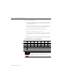
Input Filter Cutoff
Eight available input filter settings allow you to choose the best rolloff
frequency for input channels on your I/O module. When choosing a filter,
remember that time filter selection affects your input signal’s accuracy.
For example, if you choose the highest frequency of 10 Hz (filter 3), signal
noise is more likely to affect the reading, but the slowest frequency of 0.5 Hz
(filter 7) provides the most accurate signal due to incoming noise filtering.
See Table 2.2 to decide which input filter to use in your FLEX Ex
analog I/O application:
Table 2.2 Input Filter Frequency
Filter
7
6
5
4
3
2
Frequency
0.5 Hz
(2 s)
1 Hz
(1 s)
2 Hz
(500 ms)
4 Hz
(250 ms)
10 Hz
(100 ms)
Reserved
1
0
Choose the best input filter cutoff in your programming software.
Publication 1797-6.5.3 - March 2006
2-4
Understand Configurable FLEX Ex Analog Module Features
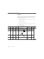
Data Format
You must choose a module data format in your user program. Formats 8, 9, 10
and 15 are not used. If they are selected for a channel quad, a configuration
fault will occur and will be reported as Diagnostic Data 2. All data for that
channel quad will be set to zero (0).
• Formats 5, 12, 13 and 14 are 2’s complement data formats, and will
return data in that form.
• 12 Formats are available
• Default format is 0 to 20 mA
• The data format selected interprets input readings and returns them to
the PLC controller
Table 2.3 1797-IE8H Data Formats
Data
Format
Format
Resolution Input
Range
0
0…20 mA
as mA
0.1% of
0…20 mA
1
0…20 mA
as %
2
Module Data Processing
Data Table Value
(Interpretation)
Count
per mA
Error
Steps
0…22 mA Datatable = 1000 (input)
0…22000
(0…22.000 mA)
1000
0.2% of
0…20 mA
0…22 mA
0…11000
(0…110.00%)
500
With
error
steps
0…20 mA 0.19% of
as √%
0…20 mA
0…22 mA
0…10488
(0…104.88%)
524
0…65535
(0…22 mA)
3276
2000…22000
(2.000…22.000
mA)
1000
( input
20 )
Datatable = 10000
√ input
20
Datatable = 10000
IF…Square_Root_Threshold
< 10000
√ input
20
Else…datatable = 0
3
0…20 mA
as
unsigned
integer
0.03% of
0…20 mA
0…20 mA
4
4…20 mA
as mA
0.1% of
4…20 mA
2…22 mA Datatable = 1000 (input)
Publication 1797-6.5.3 - March 2006
Datatable = 65535
( input
20 )
Understand Configurable FLEX Ex Analog Module Features
2-5
Table 2.3 1797-IE8H Data Formats
Data
Format
Format
Resolution Input
Range
5
4…20 mA
as %
0.16% of
4…20 mA
2…22 mA
6
4…20 mA 0.17% of
as √%
4…20 mA
4…22 mA
Module Data Processing
Data Table Value
(Interpretation)
Count
per mA
Error
Steps
( input-4
16 )
-1250 … +11250
(2’s complement)
(-12.50% …
+112.50%)
625
With
error
steps
√
0…10607
(0…106.07%)
589
With
error
steps,
underrange not
allowed
Datatable = 10000
input-4
16
IF…Square_Root_Threshold
Datatable = 10000
< 10000
√ input-4
16
Else…datatable = 0
7
4…20 mA
as
unsigned
integer
0.03% of
4…20 mA
4…20 mA
Datatable = 65535
( input-4
16 )
0…65535
(4…20 mA)
4095
With
error
steps
Datatable = 55000
( input
22 )
0…55000
(0…22 mA)
2500
All fixed
Datatable = 10000
( input-4
16 )
-250 … +10625
(2’s complement)
(-2.50…
+106.25%)
625
NAMUR
NE 4
all fixed
Datatable = 10000
( input-4
16 )
-625 … +10625
(2’s complement)
(-6.25…
+106.25%)
Datatable = 10000
( input-4
16 )
-1250 … +11250
(2’s complement)
(-12.50…
+112.50%)
8
9
Not assigned
10
11
0…20 mA
as A/D
count
0.04% of
0…20 mA
0…22 mA
12
4…20 mA
as %
0.16% of
4…20 mA
3.6…21
mA
13
4…20mA
as %
0.16% of
4…20 mA
3…21 mA
14
4…20 mA
as %
0.16% of
4…20 mA
2…22 mA
15
Not assigned
All fixed
Publication 1797-6.5.3 - March 2006
2-6
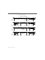
Understand Configurable FLEX Ex Analog Module Features
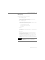
Data Formats and Error Ranges
PHYSICAL INPUT SIGNAL RANGE
0 mA
20 mA
Normal Signal Range
22 mA
Overrange
Remote Fault
Format 0
Format 1
Format 2
Format 3
20.00 mA
100.00%
100.00%
65535
0.00 mA
0.00%
0.00%
0
0 mA
Programmable
in 20
0.1 mA Steps
20 mA
Underrange
0.00 mA
-25.00%
Local
Fault
22 mA
Overrange
Normal Signal Range
Remote Fault
Remote Fault
Format 4
Format 5
Format 6
Format 7
22.00 mA
110.00%
104.88%
22 mA
Local
fault
2 mA
-12.50% Programmable
2 mA
in 20
2 mA
0.1 mA Steps
Local
Fault
4.00 mA
0.00%
0.00%
0
0 mA
20.00 mA
100.00%
100.00%
65535
20 mA
Programmable
in 20
0.1 mA Steps
22.00 mA
112.50%
106.07%
22 mA
22 mA
Overrange
Normal Signal Range
Remote Fault
Format 8
Format 9
Format 10
Format 11
Local
Fault
Not Assigned
Not Assigned
Not Assigned
0
50000
0 mA
20 mA
Underrange
Format 12
Format 13
Format 14
Format 15
Normal Signal Range
Publication 1797-6.5.3 - March 2006
-12.50%
-12.50%
-12.50%
55000
22 mA
Overrange
Remote Fault
Remote Fault
Local
Fault
-25.00%
-25.00%
-25.00%
55000
Local
Fault
Not Assigned
-2.50%
-6.25%
-12.50%
-0.00%
-0.00%
-0.00%
100.00%
100.00%
100.00%
106.25%
106.25%
112.50%
112.50%
112.50%
112.50%
41667
Understand Configurable FLEX Ex Analog Module Features
Selecting a 1797-OE8H FLEX
Ex Analog Output Module’s
Operating Features
2-7
All features of the 1797-OE8H analog output module are independently
configurable in two four-channel groups (channels 0 to 3 & channels 4 to 7).
IMPORTANT
The default selection value for all parameters is 0.
Local Fault Mode
The Local Fault Mode can be programmed to determine how the module
responds to communications faults and internal module faults.
When setting the Local Fault Mode feature in your programming software, set
this feature’s bit to 0 to use the analog fault state or digital fault state only if a
communications fault occurs. Set the bit to 1 to use the analog fault state or
digital fault state if any fault occurs.
Latch Mode
Latch Mode determines channel operation under wire off or lead break fault
conditions. This feature controls the operation of two channel groups,
channels 0 to 3 and channels 4 to 7. Channel detection occurs on a continuous
basis. If a fault is detected, the channel fault alarm is set.
If Latch Mode is enabled when a fault occurs, the fault will remain latched in
its fault state until a Global Reset (see below) is issued. If Latch Mode is
disabled when a fault occurs, the channel reports a fault until the fault is
corrected. Global Reset is not necessary if Latch Mode is disabled.
When using your programming software, set the Latch Mode bit to 0 to
disable the feature. Set the bit to 1 to enable it.
Global Reset
Global Reset works in conjunction with Latch Mode during fault conditions. If
Latch Mode is enabled and a fault condition occurs, the channel operating with
a fault remains in this condition (with analog or digital fault state implied) until
a Global Reset is issued. The Global Reset feature resets all outputs of a
particular channel group to accept normal system output data.
The Global Reset feature is an edge triggered signal. Use your programming
software to set the Global Reset bit to 1 for normal operation. Resetting of
outputs occurs during the 1 to 0 transition.
Publication 1797-6.5.3 - March 2006
2-8
Understand Configurable FLEX Ex Analog Module Features
Analog Digital State
You can configure your FLEX Ex analog output modules to work in an analog
mode or digital mode using the Analog Digital State feature. Depending on
which state you choose for your application, additional parameters (see the
descriptions of Analog Fault State and Digital Fault State on page 2-8) must be
configured for your module to react to fault conditions.
Set the Analog Digital State bit in your programming software to 0 for your
module to operate in an analog state. Set the bit to 1 for your module to
operate in a digital state. A selection bit is available to each channel.
Analog Fault State
The Analog Fault State feature determines how your I/O module reacts to
faults when a channel is used in analog mode. After a fault condition occurs,
the module may got to minimum value, maximum value, hold last state or use
analog fault state value.
Use your programming software to set the Analog Fault State bits on the I/O
module for one of the following fault reactions:
•
•
•
•
0 = minimum value
1 = maximum value
2 = hold last state
3 = use analog fault state value
You can set these parameters independently for channels 0 to 1, 2 to 3, 4 to 5,
6 to 7.
Analog Fault State Value
Specifies the fault state value of the analog output data to the module. Specific
format is controlled by the Module Data Format Control parameter. This data
is used when the channel is in analog output mode and the analog fault state is
configured to use analog fault state value.
Publication 1797-6.5.3 - March 2006
Understand Configurable FLEX Ex Analog Module Features
2-9
Digital Fault State
The Digital Fault State feature determines how your I/O module reacts to
faults when a channel is used in digital mode. After a fault condition occurs,
the module may reset channel outputs or hold last state of the outputs.
Use your programming software to set the Digital Fault State bit to 0 to reset
outputs. Set to 1 to hold last state of the outputs after a fault occurs. This
feature is available on a per channel basis.
Data Format
You must choose a module data format in your user program. See
1797-OE8H Data Formats on page 2-10 for an explanation of each bit. Data
Formats 2, 5, 6, 8, 9, 10, 12 and 15 are not assigned.
When choosing a data format, remember the following:
• If a non-assigned Analog Data Format is selected, the module sets
Diagnostic Data to 2 for configuration failure and puts affected
channels affected in the corresponding fault state.
• An unconfigured module channel pair can be assumed to have the
default configuration Analog Data Format 0, 0 to 20 mA and Analog
Mode Fault State minimum range. If a non-assigned format is selected,
then the diagnostic 2 for configuration failure is set and the module
channel pair goes to the default fault state minimum range.
• If the configuration had been changed, from the default, and then it was
changed again to a non-assigned format, then the diagnostic bit 2 for
configuration failure is set and the module goes to the fault state for the
last valid configuration.
• Formats 13 and 14 are 2’s complement data formats, and require data to
the module in that form.
• Range: 0 to 15
• Default: 0
• Data Table Reference: data format, word 12 and 13, bits 0 to 3, bits 4 to
7
Publication 1797-6.5.3 - March 2006
2-10
Understand Configurable FLEX Ex Analog Module Features
If data is sent to the module which is out of range, the value will be clipped and
Diagnostic Data will be set to 11 data out of range.
datatable
20.000
16.000
Diagnostic Data error
11=data out of range
12.000
8.000
4.000
0.000
Diagnostic Data error
11=data out of range
-4.000
0
4
8
12 16
Output mA
20
24
Table 2.4 1797-OE8H Data Formats
Data
Format
Format
Resolution Full
Output
Range
0
mA as
0…20 mA
0.1% of
0…20 mA
0…22 mA
1
% as
0…20 mA
0.2% of
0…20 mA
0…22 mA
2
—
—
—
3
Unsigned
integer as
0…20 mA
0.03% of
0…20 mA
0…20 mA
4
mA as
4…20 mA
0.1% of
4…20 mA
2…22 mA
5
—
—
—
Unsigned
integer as
4…20 mA
0.03% of
4…20 mA
4…20 mA
Module Data Processing
Output =
( datatable
1000 )
Output = 20
( datatable
10000 )
Not assigned
Output = 20
Output =
( datatable
65535 )
( datatable
1000 )
Not assigned
Data Table Value
(Interpretation)
Count
per mA
Analog Fault
State
0…22000
(0…22.000 mA)
1000
Min=0 mA
Max=22 mA
Hold
last=hold
50%=11 mA
0…11000
(0…110.00%)
500
Min=0 mA
Max=22 mA
Hold
last=hold
50%=11 mA
—
—
—
0…65535
(0…22 mA)
3276
Min=0 mA
Max=20 mA
Hold
last=hold
50%=10 mA
2000…22000
(2.000…22.000
mA)
1000
Min=2 mA
Max=22 mA
Hold
last=hold
50%=12 mA
—
—
—
0…65535
(4…20 mA)
4095
Min=4 mA
Max=20 mA
Hold
last=hold
50%=12 mA
6
7
Publication 1797-6.5.3 - March 2006
Output = 16
+4
( datatable
65535 )
Understand Configurable FLEX Ex Analog Module Features
2-11
Table 2.4 1797-OE8H Data Formats
Data
Format
Format
Resolution Full
Output
Range
Module Data Processing
Data Table Value
(Interpretation)
Count
per mA
Analog Fault
State
8
—
—
—
Not assigned
—
—
—
11
D/A count
as 0…20
mA
0.28% of
0…20 mA
0…22 mA
0…8000
(0…22 mA)
363
Min=0 mA
Max=22 mA
Hold
last=hold
50%=11 mA
12
4…20 mA
—
—
—
—
—
13
% as
4…20 mA
0.16% of
4…20 mA
3…21 mA
14
% as
4…20 mA
0.16% of
4…20 mA
2…22 mA
15
—
—
—
9
10
Output = 22
( datatable
)
8000
Not assigned
Output = 16
+4
( datatable
10000 )
-625 …+10625
(2’s complement)
(-6.25…+106.25
%)
625
Min=3 mA
Max=21 mA
Hold
last=hold
50%=12 mA
Output = 16
+4
( datatable
10000 )
-1250…+11250
(2’s complement)
(-12.50…+112.5
0%)
625
Min=2 mA
Max=22 mA
Hold
last=hold
50%=12 mA
—
—
—
Not assigned
Fault Alarm
Fault Alarm selects whether the channel pair fault detection is enabled or
disabled. There is a 100 Hz (10 ms) filter for wire off/lead break detection.
Use your programming software to set the Fault Alarm. Set the feature bit to 0
to disable the alarm. Set the bit to 1 to enable wire off/lead break fault
detection.
Publication 1797-6.5.3 - March 2006
2-12
Understand Configurable FLEX Ex Analog Module Features
Understanding Image Table Bit Descriptions
Mapping and Bit/Word
Use the table below to understand bits used in image table mapping and
Descriptions
bit/word descriptions. Complete definitions of these feature documented
below can be found in Chapter 2.
Table 2.5 Bit/Word Descriptions
Publication 1797-6.5.3 - March 2006
Bit(s)
Location
Definition
Ch
1797-IE8H Input and output maps
1797-OE8H Input and output maps
Channel
Ovr Alm
1797-IE8H Input map
Overrange Alarm
Und Alm
1797-IE8H Input map
Underrange Alarm
Rm Flt
1797-IE8H Input map
Remote Fault
Lo Flt
1797-IE8H Input map
Local Fault
Res Flg
1797-IE8H Input map
1797-OE8H Input map
Response Flag
U/D
1797-IE8H Output map
Up/down
Flt Md
1797-IE8H Output map
Fault Module
Cd Flg
1797-IE8H Output map
1797-OE8H Output map
Command Flag
Flt Alm
1797-OE8H Input map
Fault Alarm
Glbl Rst
1797-OE8H Output map
Global Reset
Lo Flt Md
1797-OE8H Output map
Local Fault Module
Alg Flt Ste
1797-OE8H Output map
Analog Fault State
Lth Rty
1797-OE8H Output map
Latch Retry
Dig Flt Ste
1797-OE8H Output map
Digital Fault State
Alg Dig Md
1797-OE8H Output map
Analog Digital Module
Diagnostic
Status
1797-IE8H Input map
1797-OE8H Input map
Diagnostic Status
HRBD
1797-IE8H Input map
1797-OE8H Input map
HART Rebuild Flag
HRB
1797-IE8H Input map
1797-OE8H Input map
HART Readback Flag
HFAIL
1797-IE8H Input map
1797-OE8H Input map
HART Failure Flag
HTMT
1797-IE8H Input map
1797-OE8H Input map
HART Transmitter
Flag
HCM
1797-IE8H Input map
1797-OE8H Input map
HART Communication
Flag
Understand Configurable FLEX Ex Analog Module Features
2-13
Analog Input Module (1797-IE8H) Image Table Mapping
Table 2.6 Input Map (Read Words)
→
Word ↓
Bit
0
1
2
3
4
5
6
7
8
9
15
14
13
12
Where:
11
10
09
04
03
Channel 0 Input Data
Channel 1 Input Data
Channel 2 Input Data
Channel 3 Input Data
Channel 4 Input Data
Channel 5 Input Data
Channel 6 Input Data
Channel 7 Input Data
Ovr
Ovr
Und Und Und Und
Alm Alm Alm Alm Alm Alm
ch
ch
ch
ch
ch
ch
1
0
7
6
5
4
Rm
Rm
Lo
Lo
Lo
Lo
Flt
Flt
Flt
Flt
Flt
Flt
ch
ch
ch
ch
ch
ch
1
4
5
6
7
0
H
Reserved
Rbd
H
H
H
H
H
H
Fail
Fail
Fail
Fail
Rb
Rb
ch
ch
ch
ch
ch
ch
4
5
6
7
0
1
H
H
H
H
H
H
Cm
Cm
Cm
Cm
Tmt Tmt
ch
ch
ch
ch
ch
ch
4
5
6
7
0
1
Und
Alm
ch
3
Lo
Flt
ch
3
Ovr
Alm
ch
7
Rm
Flt
ch
7
Ovr
Alm
ch
6
Rm
Flt
ch
6
Ovr
Alm
ch
5
Rm
Flt
ch
5
Ovr
Ovr
Alm Alm
ch
ch
4
3
Rm
Rm
Flt
Flt
ch
ch
3
4
Reserved
Ovr
Alm
ch
2
Rm
Flt
ch
2
H
Rb
ch
7
H
Tmt
ch
7
H
Rb
ch
6
H
Tmt
ch
6
H
Rb
ch
5
H
Tmt
ch
5
H
Rb
ch
4
H
Tmt
ch
4
H
Rb
ch
3
H
Tmt
ch
3
H
Rb
ch
2
H
Tmt
ch
2
10
11
12
08
07
06
05
H
Fail
ch
3
H
Cm
ch
3
02
01
Und Und
Alm Alm
ch
ch
2
1
Lo
Lo
Flt
Flt
ch
ch
1
2
Diagnostic Status
H
Fail
ch
2
H
Cm
ch
2
H
Fail
ch
1
H
Cm
ch
1
00
Und
Alm
ch
0
Lo
Flt
ch
0
H
Fail
ch
0
H
Cm
ch
0
ch = channel
Ovr Alm = Over Range Alarm
Und Alm = Under Range Alarm
Rm Flt = Remote Fault
Lo Flt = Local Fault
H Rbd = HART Rebuild
H Rb = HART Readback
H Fail = HART Failure
H Tmt = HART Transmitter
H Cm = HART Communication
Publication 1797-6.5.3 - March 2006
2-14
Understand Configurable FLEX Ex Analog Module Features
Table 2.7 Configuration Map (Write Words)
→
Word ↓
Bit
15
14
13
12
11
10
09
08
07
06
05
04
03
02
00
Write
0
Reserved
High and Low Error Level 0…3
U/D
0…3
Filter Cutoff 0…3
Data Format 0…3
1
Sqrt
High and Low Error Level 4…7
U/D
4…7
Filter Cutoff 4…7
Data Format 4…7
Where:
01
U/D = up/down
Flt Md = Fault Module
Sqrt = Square Root
Bit/Word Description for the Analog Input Module
(1797-IE8H)
Table 2.8 Fault Mode - Write Words 0 and 1
Word 0 Bit 00
Word 1 Bit 00
Where:
Fault enable for channels 0…3
Fault enable for channels 4…7
0 = disabled
1 = enable with wire-off and overload or short circuit
Table 2.9 Add-on Filter Selections - Write Words 0 and 1
Word
0
1
Bits
07
07
0
0
0
0
1
1
1
1
Description
06 05 Channels 0…3
06 05 Channels 4…7
0 0 Reserved
0 1
1 0
1 1 10 Hz (100 ms)
0 0 4 Hz (250 ms)
0 1 2 Hz (500 ms)
1 0 1 Hz (1 s)
1 1 0.5 Hz (2 s)
Table 2.10 Remote Transmitter Error Up/Down - Write Words 0 and 1
Word 0 Bit 08
Word 1 Bit 08
Where:
Publication 1797-6.5.3 - March 2006
Up/down channels 0…3
Up/down channels 4…7
0 = remote fault is enabled by transmitter overrange
1 = remote fault is enabled by transmitter underrange
Flt
Md
0…3
Flt
Md
4…7
Understand Configurable FLEX Ex Analog Module Features
2-15
Table 2.11 Data Format - Write Words 0 and 1
Bits
Word 0 04 03
Word 1 04 03
0 0
0 0
0 0
0 0
Description
Data format for channels 0…3
Data format for channels 4…7
0…22 mA, w/error steps (default)
0…22 mA = 0…110%, w/error steps
0…22 mA = 0…104.8%, square root, w/error steps
0…22 mA = 0…65,535, unsigned integer, w/error
steps
0 1 0 0 2…22 mA, w/error steps
0 1 0 1 2…22 mA = -12.5…112.5%, w/error steps
0 1 1 0 4…22 mA = 0…106%, square root, w/error steps
0 1 1 1 4…20mA = 0…65,535, unsigned integer, w/error steps
1 0 0 0 Not assigned
1 0 0 1 Not assigned
1 0 1 0 Not assigned
1 0 1 1 0…22 mA = A/D count, w/fixed error
1 1 0 0 3.6…21 mA = NAMUR NE 43, w/fixed error
1 1 0 1 3…21 mA = -6.25…106.28% w/fixed error
1 1 1 0 2…22 mA = -12.5…112.5% w/fixed error
1 1 1 1 Not assigned
Table 2.12 Error Level 0.1mA Steps
Word 0
Word 1
Data
Format
2…22
mA
-12.5…
112.5%
02
02
0
0
1
1
01
01
0
1
0
1
Bits
13 12 11 10 9
13 12 11 10 9
0 0 0 0 0
0
0
1
1
1
0
1
1
1
1
Description
Error level channels 0…3
Error level channels 4…7
Disabled
0.1 mA * step value = remote fault alarm threshold
Examples
Step value = 7, 0.1 mA * 7 = 0.7 mA
Remote fault alarm at -4.38% or +104.38%
Binary value = 15, 0.1 mA * 15 = 1.5 mA
Remote fault alarm at -9.38% or + 109.38%
Publication 1797-6.5.3 - March 2006
2-16
Understand Configurable FLEX Ex Analog Module Features
Analog Output Module (1797-OE8H) Image Table Mapping
Table 2.13 Input Map (Read Words)
→
Word ↓
15
14
13
12
11
10
09
0
Flt
Alm
ch7
Flt
Alm
ch6
Flt
Alm
ch5
Flt
Alm
ch4
Flt
Alm
ch3
Flt
Alm
ch2
Flt
Alm
ch1
H
Rb
ch 7
H
Tmt
ch 7
H
Rb
ch 6
H
Tmt
ch 6
H
Rb
ch 5
H
Tmt
ch 5
H
Rb
ch 4
H
Tmt
ch 4
H
Rb
ch 3
H
Tmt
ch 3
H
Rb
ch 2
H
Tmt
ch 2
H
Rb
ch 1
H
Tmt
ch 1
11
10
09
Bit
1
2
3
08
07
Flt
Alm
ch0
Reserved
H
H
Fail
Rb
ch 0 ch 7
H
H
Cm
Tmt
ch 0 ch 7
06
05
04
03
Reserved
02
01
00
Diagnostic Status
H
Fail
ch 6
H
Cm
ch 6
H
Fail
ch 5
H
Cm
ch 5
H
Fail
ch 4
H
Cm
ch 4
H
Fail
ch 3
H
Cm
ch 3
H
Fail
ch 2
H
Cm
ch 2
H
Fail
ch 1
H
Cm
ch 1
H
Fail
ch 0
H
Cm
ch 0
06
05
04
03
02
01
00
Dig
Dig
Out
Out
ch 7 ch 6
Channel 0 Output Data
Channel 1 Output Data
Channel 2 Output Data
Channel 3 Output Data
Channel 4 Output Data
Channel 5 Output Data
Channel 6 Output Data
Channel 7 Output Data
Dig
Out
ch 5
Dig
Out
ch 4
Dig
Out
ch 3
Dig
Out
ch 2
Dig
Out
ch 1
Dig
Out
ch 0
Where: ch = channel
Flt Alm = Fault Alarm
H Rbd = HART Rebuild
H RB = HART Readback
H Fail = HART Failure
H Tmt = HART Transmitter
H Cm = HART Communication
Table 2.14 Output Map (Write Words)
→
Word ↓
15
14
0
Rese
rved
Glbl
Rst
Bit
13
1
2
3
4
5
6
7
8
Where: ch = channel
Dig Out = Digital Output
Glbl Rst = Global Reset
Publication 1797-6.5.3 - March 2006
12
Reserved
08
07
Understand Configurable FLEX Ex Analog Module Features
2-17
Table 2.15 Configuration Map (Write Words)
Bit
→
15
14
13
12
11
10
09
08
07
06
05
04
03
02
01
0
Lo Flt
Md
Rese
rved
Flt
Flt
Md
Md
ch
ch
2…3 0…1
Alg Flt
Ste
ch
2…3
Alg Flt
Ste
ch
0…1
Data Format
ch 2…3
Data Format
ch 0…1
1
Flt
Flt
Lth
Lth
Md
Md
Md
Md
ch
ch
ch
ch
4…7 0…3 6…7 4…5
Alg Flt
Ste
ch
6…7
Alg Flt
Ste
ch
4…5
Data Format
ch 6…7
Data Format
ch 4…5
2
Dig
Flt
Ste
ch 7
00
Word ↓
Dig
Flt
Ste
ch 6
Dig
Flt
Ste
ch 5
Dig
Flt
Ste
ch 4
Dig
Flt
Ste
ch 3
Dig
Flt
Ste
ch 2
Dig
Flt
Ste
ch 1
Dig
Flt
Ste
ch 0
Alg
Dig
Md
ch 7
Alg
Dig
Md
ch 6
3
Analog Fault State Value Channel 0
4
Analog Fault State Value Channel 1
5
Analog Fault State Value Channel 2
6
Analog Fault State Value Channel 3
7
Analog Fault State Value Channel 4
8
Analog Fault State Value Channel 5
9
Analog Fault State Value Channel 6
10
Analog Fault State Value Channel 7
Where:
Alg
Dig
Md
ch 5
Alg
Dig
Md
ch 4
Alg
Dig
Md
ch 3
Alg
Dig
Md
ch 2
Alg
Dig
Md
ch 1
Alg
Dig
Md
ch 0
ch = channel
Lo Flt Md = Local Fault Mode
Flt Md = Fault Mode
Alg Flt Ste = Analog Fault State
Lth Md = Latch Mode
Dig Flt Ste = Digital Fault State
Alg Dig Md = Analog/Digital Mode
Cd Flg = Command Flag
Publication 1797-6.5.3 - March 2006
2-18
Understand Configurable FLEX Ex Analog Module Features
Table 2.16 Data Format Control
Data
Format
0 0 0
0
0
0
0
1
0
0
0
0
1
1
0
1
0
1
0
0
0
0
0
1
1
1
0
1
1
1
0
1
1
1
1
1
0
0
0
0
0
0
1
1
0
1
0
1
1
1
1
1
0
0
0
1
1
1
1
0
1
1
1
1
Publication 1797-6.5.3 - March 2006
Range
Resolution
Data Table
Value
0…2000
Count per
mA
1000
0…110%
0…11000
500
0…20 mA Unsigned
integer
2…22 mA 2…22 mA
0…65535
3276
2000…
22000
1000
4…20 mA 0.03% of
4…20 mA
Not assigned
4…20 mA Unsigned
integer
0…65535
4095
0…20 mA 0.28% of
0…20 mA
Not assigned
4…20mA 0.16% of
4…20 mA
0…22 mA D/A count
0…8000
363
3…21 mA -6.25…
+106.25%
2…22 mA -12.5…
+112.5%
-625…
+10625
-1250…
+11250
625
0…20 mA 0.1% of
0…20 mA
0.2% of
0…20 mA
Not assigned
4…20 mA 0.03% of
0…20 mA
0.1% of
4…20 mA
Not assigned
Not assigned
Full
Interpretation
Range
0…22 mA 0…22 mA
625
Understand Configurable FLEX Ex Analog Module Features
2-19
The FLEX Ex HART modules are addressed by using an MSG or CIO
instruction. When using one of these instructions, configure it to the
following:
1797-IE8H and -OE8H
Extended Configuration
Data Table
• Class: 0x7D
• Instance: Slot number (range from 1 to 8 with 1 being the I/O
module closest to the adapter
• Attribute: 0x66
• Service: 0x0E for a get attribute single or 0x10 for a set attribute single
Also, configure the communication path to the target I/O module.
For a set attribute single, configure two words as defined in the Extended
Configuration Data Table to be sent to the I/O module.
For a get attribute single, two words configured as defined in the Extended
Configuration Data Table will be returned from the instruction.
Table 2.17 1797-IE8H and -OE8H Extended Configuration Data Table
Bit
→
15
14
13
12
11
10
09
08
07
06
05
04
03
02
01
00
PMI
ch 7
PMI
ch 6
PMI
ch 5
PMI
ch 4
PMI
ch 3
PMI
ch 2
PMI
ch 1
PMI
ch 0
SME
ch 7
SME
ch 6
SME
ch 5
SME
ch 4
SME
ch 3
SME
ch 2
SME
ch 1
SME
ch 0
HS
LED
HS
Inht
50/
60 Hz
Word ↓
0
1
Where:
Reserved
HART Read Back Threshold
ch 4…7
HART Read Back Threshold
ch 0…3
ch = channel
PMI = Primary Master Inhibit
SME = Secondary Master Enable
HS LED = HART Status LEDs
HS Inht = HART Status Inhibit
Publication 1797-6.5.3 - March 2006
2-20
Understand Configurable FLEX Ex Analog Module Features
Secondary Master Enable (SME) and Primary Master Inhibit (PMI)
These two bits control a few module internal functions individually for
channels 0 to 7.
Table 2.18
Bits(1)
1 (Default)
2
3
4
PMI
8, 9, 10, 11, 12, 13, 14, 15
0
0
1
1
SME
0, 1, 2, 3, 4, 5, 6, 7
0
1
0
1
On
Off
On
Rebuild On
On
Off
Off
HART Read Back On
On
Off
Off
Primary Master On
On
Off
Off
Secondary Master Off
On
Off
On
HART Smooth Filter Pulsed
1 Where:
Ch0 - bits 0 and 8; Ch1 - bits 1 and 9; Ch2 - bits 2 and 10; Ch3 - bits 3 and 11;
Ch4 - bits 4 and 12; Ch5 - bits 5 and 13; Ch6 - bits 6 and 14; Ch7 - bits 7 and 15
HART Status LEDs
When this bit is set, the LEDs are used for HART diagnostics. LED behavior
changes to show communication on HART with each LED representing a
HART loop. A flashing yellow LED indicates that communication is currently
being processed while a solid yellow LED means that this device is in the
transmitter list.
HART Status Inhibit
When this bit is set, the HART communication status is not shown in the
realtime data table to enable compatibility. The appropriate areas are cleared
with zeroes.
50/60 Hz Filter
The values are:
• 0 = 50 Hz (default)
• 1 = 60 Hz
Publication 1797-6.5.3 - March 2006
Understand Configurable FLEX Ex Analog Module Features
2-21
HART Read Back Threshold
This bit delivers the percentage value, in steps of 1%, of the threshold for
forcing the HART read back indication. The maximum input signal deviation
for HART analog modules is 31%.
If there is no HART transmitter on the loop or if the loop is not in the
transmitter list, the function is switched off internally in the I/O module.
The values are:
• 0 = disabled (default)
• 1 to 4 = not supported from the I/O module (set to 5 internally)
• 5 to 31 = percentage threshold data (5 to 31%)
Chapter Summary
In this chapter, we told you about the FLEX Ex system and the analog I/O
modules, and how they communicate with programmable controllers. Move to
Chapter 3 to learn how to install your FLEX Ex analog module.
Publication 1797-6.5.3 - March 2006
2-22
Understand Configurable FLEX Ex Analog Module Features
Notes:
Publication 1797-6.5.3 - March 2006
Chapter
3
How to Install Your FLEX Ex Analog Modules
What This Chapter Contains
Before You Install Your
Analog Module
Read this chapter to install the input and output analog modules.
For
See
Before You Install Your Analog Module
3-1
Compliance to European Union Directives
3-2
Installation in Zone 1
3-3
Removal and Insertion Under Power
3-4
Install the Module
3-4
Connecting Wiring to the FLEX Ex I/O
Analog Modules
3-11
Ground the Module
3-14
Chapter Summary
3-15
Before installing your FLEX Ex analog module:
Table 3.1 Steps to Complete Before Installation
You Need To
As Described Under
Verify that the module will be installed in a
suitable metal enclosure
Installation in Zone 1, page 3-3
Position the keyswitch on the
terminal base
Installing the Module, page 3-9
ATTENTION
1
These modules do not receive primary operational power from
the backplane. +/-V dc power must be applied to your module
before installation. If power is not applied, the module position
will appear to the adapter as an empty slot in your chassis.
Publication 1797-6.5.3 - March 2006
3-2
How to Install Your FLEX Ex Analog Modules
Compliance to European
Union Directives
If these products have the CE mark they are approved for installation within
the European Union and EEA regions. They have been designed and tested to
meet the following directives.
EMC Directive
These products are tested to meet the Council Directive 89/336/EC
Electromagnetic Compatibility (EMC) as amended by 92/31/EC and
93/68/EEC, by applying the following standards:
• EN61000-6-4:2001, Electromagnetic Compatibility (EMC) - Part 6-4:
Generic Standard for Industrial Environments (Class A)
• EN61000-6-2:2001, Electromagnetic Compatibility (EMC) - Part 6-2:
Generic Standards - Immunity for Industrial Environments
• EN61326-1997 + A1-A2, Electrical Equipment For Measurement,
Control, and Laboratory Use - Industrial EMC Requirements
ATEX Directive
These products are tested in conjunction with associated I/O modules to meet
the Council Directive 94/9/EC (ATEX) Equipment and Protective Systems
Intended for Use in Potentially Explosive Atmospheres by applying the
following standards:
• EN50014:1997 + A1-A2, Electrical Apparatus for Potentially Explosive
Atmospheres
• EN50020:1994, Electrical Apparatus for Potentially Explosive
Atmospheres - Intrinsic Safety “i”
• EN50284:1999, Special Requirements for Construction, Test and
Marking of Electrical Apparatus of Equipment Group II, Category 1G
• EN50281-1-1:1998 + A1, Electrical Apparatus for Use in the Presence
of Combustible Dust - Part 1-1: Protection by Enclosure
Publication 1797-6.5.3 - March 2006
How to Install Your FLEX Ex Analog Modules
Installation in Zone 1
These modules must not be exposed to the environment. Provide a suitable
metal enclosure. These modules have a protection factor of IP20.
WARNING
Installation in Zone 22
3-3
These modules cannot be used in an intrinsically safe
environment after they have been exposed to nonintrinsically
safe signals.
When the module is installed in Zone 22, the following cabinets must be used:
IVK-ISRPI-V16LC; IVK-ISRPI-V8HYW; or IVK-ISRPI-V8LC. These
cabinets can be purchased from:
Pepperl+Fuchs GmbH
Konigsberger Allee 85-87, D-68307
Mannheim, Germany
Attn: PA Sales Dept.
Kirsten Becker
Telephone +49 776 1298
www.pepperl-fuchs.com
The IS-RPI cabinets (type IVK2-ISRPI-V8LC, IVK2-ISRPI-V8HYW, or
IVK-ISRPI-V16LC) ensures the basic protection for the intrinsically safe
apparatus of the IS-RPI system for use in Zone 22. It corresponds with
category 3D according to RL 94/9 EG and with the type label marked with
the following information:
Pepperl+Fuchs GmbH
68301 Mannheim
IVK2-ISRPI-V8LC (or IVK2-ISRPI-V8HYW or IVK-ISRPI-V16LC)
II 3D IP54 T 70°C
CE
Serial (manufacturing) number
Model
Electrostatic Charge
Protect the system against electrostatic charge. Post a sign near this module:
Attention! Avoid electrostatic charge. For your convenience, a sign which
can be cut out and posted is included in this user manual before the back
cover.
Publication 1797-6.5.3 - March 2006
3-4
How to Install Your FLEX Ex Analog Modules
Removal and Insertion
Under Power
WARNING
These module are designed so you can remove and insert them
under power. However, take special care when removing or
inserting these modules in an active process. I/O attached to
any module being removed or inserted can change states due to
its input/output signal changing conditions.
If you insert or remove the terminal base while backplane
power is on, an electrical arc can occur. This could cause an
explosion in hazardous location installations.
Be sure that power is removed or the area is nonhazardous
before proceeding.
Install the Module
Installation of the analog module consists of:
• Mounting the terminal base unit
• Installing the analog I/O module into the terminal base unit
• Installing the connecting wiring to the terminal base unit
If you are installing your module into a terminal base unit that is already
installed, proceed to Mounting the Analog Modules on the Terminal Base on
3-9.
ATTENTION
Make certain that you power this terminal base module
combination with an instrinsically safe power supply. Do not
exceed the values listed in the specifications for the terminal base
or module.
Do not use the unused terminals on the terminal base unit. Using
the terminals as supporting terminals can result in damage to
modules and/or unintended operation of your system.
Publication 1797-6.5.3 - March 2006
How to Install Your FLEX Ex Analog Modules
3-5
Mount on a DIN Rail
ATTENTION
Do not remove or replace a terminal base unit when power is
applied. Interruption of the flexbus can result in unintended
operation or machine motion.
1. Remove the cover plug in the male connector of the unit to which you
are connecting this terminal base unit.
2. Check to make sure that the 16 pins in the male connector on the
adjacent device are straight and in line so that the mating female
connector on this terminal base unit will mate correctly.
3. Make certain that the female flexbus connector is fully retracted into
the base unit.
4. Position the terminal base over the 35 x 7.5mm DIN rail A
(A-B pt. no. 199-DR1).
A
A
Position terminal base at a slight angle and
hooked over the top of the DIN rail A.
41106
Publication 1797-6.5.3 - March 2006
3-6
How to Install Your FLEX Ex Analog Modules
41107
Slide the terminal base over tight against the adapter (or proceeding terminal
base). Make sure the hook on the terminal base slides under the edge of the
adapter (or proceeding terminal base) and the flexbus connector is fully retracted.
ATTENTION
Do not force the terminal base into the adjacent modules.
Forcing the units together can bend or break the hook and allow
the units to separate and break communication over the
backplane.
5. Rotate the terminal base onto the DIN rail with the top of the rail
hooked under the lip on the rear of the terminal base.
Use caution to make sure that the female flexbus connector does
not strike any of the pins in the mating male connector.
41108
Press down on the terminal base unit to lock the terminal base on the DIN rail. If
the terminal base does not lock into place, use a screwdriver or similar device to
open the locking tab, press down on the terminal base until flush with the DIN rail
and release the locking tab to lock the base in place.
41109
Gently push the flexbus connector into the side of the adapter (or proceeding
terminal base) to complete the backplane connection.
Publication 1797-6.5.3 - March 2006
How to Install Your FLEX Ex Analog Modules
3-7
6. For specific wiring information, refer to the installation instructions for
the module you are installing in this terminal base unit.
Terminal assignments are also given later in this chapter, see page 3-11.
7. Repeat the above steps to install the next terminal base.
8. Be sure the flexbus connector cover on the last terminal base is in place.
Panel/Wall Mount
Installation on a wall or panel consists of:
• Laying out the drilling points on the wall or panel
• Drilling the pilot holes for the mounting screws
• Mounting the adapter mounting plate
• Installing the terminal base units and securing them to the wall or panel
If you are installing your module into a terminal base unit that is already
installed, proceed to Mounting the Analog Modules on the Terminal Base Unit
on page 3-9.
Use the mounting kit Cat. No. 1794-NM1 for panel/wall mounting.
1.4
(35.5)
1 - Mounting Plate for Adapter
2 - 18 #6 Self-tapping Screws
(2 for the Adapter, and 2
Each for Up to 8 Modules)
1
2
Adapter Module
(Not Included)
41547
Terminal Base Unit
(Not Included)
Publication 1797-6.5.3 - March 2006
3-8
How to Install Your FLEX Ex Analog Modules
To install the mounting plate on a wall or panel:
1. Lay out the required points on the wall/panel as shown in the drilling
dimension drawing.
Drilling Dimensions for Panel/Wall Mounting of FLEX Ex I/O
35.5
(0.51)
58.5
(2.3)
35.5
(1.4)
58.5
(2.3)
35.5
(1.4)
40.5
(1.6)
15.6
(0.61)
8
(0.3)
.83 (21)
50
(2.0)
mm
(In)
!
ATTENTION: Be careful of metal chips when
drilling cable mounting holes. Do not drill holes
above a system that has any modules installed.
Cable length
approximately
292.1 (11.5) or
901.0 (35.5) from
upper connector
[length depends
upon cable - 0.3 m
(1 ft) or 0.091 m
(3 ft)]
+V
1
-V
2
+V
3
-V
4
40871
2. Drill the necessary holes for the #6 self-tapping mounting screws.
3. Mount the mounting plate (1) for the adapter module using two #6
self-tapping screws (18 included for mounting up to 8 modules and the
adapter).
IMPORTANT
Make certain that the mounting plate is properly grounded to
the panel. Refer to Industrial Automation Wiring and Grounding
Guidelines, publication 1770-4.1.
4. Hold the adapter (2) at a slight angle and engage the top of the
mounting plate in the indention on the rear of the adapter module.
5. Press the adapter down flush with the panel until the locking lever locks.
Publication 1797-6.5.3 - March 2006
How to Install Your FLEX Ex Analog Modules
3-9
6. Position the terminal base unit up against the adapter and push the
female bus connector into the adapter.
7. Secure to the wall with two #6 self-tapping screws.
8. Repeat for each remaining terminal base unit.
Mounting the Analog Modules on the Terminal Base Unit
The analog input and output modules mount on a 1797-TB3 or TB3S
intrinsically safe terminal base unit.
1. Rotate keyswitch (1) on terminal base unit (2) clockwise to position 3 for
the 1797-IE8H or position 4 for the 1797-OE8H as required for each
type of module.
Do not change the position of the keyswitch after wiring the
terminal base unit.
7
3
1
8
2
6
4
5
40231
Label under here
or under here
2. Make certain the flexbus connector (3) is pushed all the way to the left
to connect with the neighboring terminal base/adapter. You cannot
install the module unless the connector is fully extended.
Publication 1797-6.5.3 - March 2006
3-10
How to Install Your FLEX Ex Analog Modules
3. Make sure the pins on the bottom of the module are straight so they will
align properly with the connector in the terminal base unit.
4. Position the module (4) with its alignment bar (5) aligned with the
groove (6) on the terminal base.
5. Press firmly and evenly to seat the module in the terminal base unit.
The module is seated when the latching mechanism (7) is locked into
the module.
6. Make certain that you only connect terminal base units to other
intrinsically safe system modules or adapters to maintain the integrity of
the intrinsically-safe backplane.
7. Remove cap plug (8) and attach another intrinsically safe terminal base
unit to the right of this terminal base unit if required.
Make sure the last terminal base has the cap plug (8) in place.
41307
The adapter is capable of addressing eight modules. Do not exceed a maximum of
eight terminal base units in your system.
Wire the Terminal Base
Units
Wiring the FLEX Ex I/O analog modules is done through the 1797-TB3 and
1797-TB3S terminal base units.
ATTENTION
The FLEX Ex analog I/O modules do not receive primary
operational power from the backplane. +/-V dc power must be
applied to your module before operation. If power is not
applied, the module position will appear to the adapter as an
empty slot in your chassis. If the adapter does not recognize
your module after installation is completed, cycle power to the
adapter.
Make certain that you power these modules with an
intrinsically safe power supply. Do not exceed the values listed
in the specifications for the modules.
Publication 1797-6.5.3 - March 2006
How to Install Your FLEX Ex Analog Modules
Connecting Wiring to the
FLEX Ex I/O Analog
Modules
3-11
Inputs/Outputs
Each 1797-IE8H input can be operated from an analog field device signal, and
each 1797-OE8H output channel can operate an analog field device. Do not
apply any non-intrinsically safe signals to these modules.
When using an intrinsically safe electrical apparatus according
to EN50020, the European Community directives and
regulations must be followed.
IMPORTANT
The channels of the 1797-IE8H are electrically connected to each other and
have a common plus-line. The channels of the 1797-OE8H are electrically
connected to each other.
When interconnecting several lines, you must consider the total
accumulated power and check for intrinsic safety.
IMPORTANT
Connections for the 1797-IE8H Module
+V
-V
+
91 Ω
17V
Bus
flexbus
4 to 20mA
Xmit
I
4 to 20mA
Xmit
IP
P
sig
uC
22 Ω
40072
1797-IE8H Module
0
1
2
+
sig
–
3
4
5
6
+
sig
–
7
8
9
10
+
sig
–
11
12
13
14
+
sig
–
15
Row A
Ch 0
16
Ch 1
17
18
19
+
sig
–
20
Ch 2
21
22
23
+
sig
–
24
Ch 3
25
26
27
+
sig
–
28
29
30
31
+
sig
–
32
33
Row B
Ch 4
34
35
+V
–V
Ch 5
36
37
38
39
Ch 6
40
41
42
43
Ch 7
44
45
46
47
48
49
50
51
Row C
40071
+V –V
No connection
allowed
No connection
allowed
Publication 1797-6.5.3 - March 2006
3-12
How to Install Your FLEX Ex Analog Modules
For Two-Wire Transmitter Devices
1. Connect the individual input wiring to (+) terminals (0, 4, 8, 12) on the 0
to 15 row (A) and on the 16 to 33 row (B) (terminals 17, 21, 25, 29) as
indicated in the table below.
2. Connect the associated input to the corresponding (sig) terminal (1, 5, 9,
13) on the 0 to 15 row (A), and on the 16 to 33 row (B) (terminals 18,
22, 26, 30) for each input as indicated in the table below.
3. Connect +V dc power to terminal 34 on the 34 to 51 row (C).
4. Connect -V to terminal 35 on the 34 to 51 row (C).
5. If continuing power to the next terminal base unit, connect a jumper
from terminal 50 (+V) on this base unit to terminal 34 on the next base
unit.
6. If continuing common to the next terminal base unit, connect a jumper
from terminal 51 (-V) on this base unit to terminal 35 on the next base
unit.
Table 3.2 Wiring Connections for the 1797-IE8H Module
Input
Input
Source
Input
Signal
Input
Return
Input
Input
Source
Input
Signal
Input
Return
Input 0
A-0
A-1
A-2
Input 4
B-17
B-18
B-19
Input 1
A-4
A-5
A-6
Input 5
B-21
B-22
B-23
Input 2
A-8
A-9
A-10
Input 6
B-25
B-26
B-27
Input 3
A-12
A-13
A-14
Input 7
B-29
B-30
B-31
+V
Terminals 34 and 50
-V
Terminals 35 and 51
Terminals 16, 33, 40, 41, 42, 43, 44 and 45 are connected to chassis ground.
ATTENTION
Publication 1797-6.5.3 - March 2006
Do not use the unused terminals on the terminal base unit.
Using these terminals as supporting terminals can result in
damage to the module and/or unintended operation of your
system.
How to Install Your FLEX Ex Analog Modules
3-13
Connections for the 1797-OE8H Module
+V power
-V supply
+
Bus
flexbus
uC
4 to 20mA
valve
- 4 to 20mA
actuator
41441
1797-OE8H Module
Row A
0
1
+ ch0
16
2
3
4
5
+ ch1
6
7
8
9
+ ch2
10 11 12 13 14 15
+ ch3
17 18 19 20 21 22 23 24 25 26 27 28 29 30 31 32 33
Row B
+ ch4
34
+ ch5
+ ch6
+ ch7
35 36 37 38 39 40 41 42 43 44 45 46 47 48 49 50 51
Row C
+V -V
+V -V
41440
No connections allowed to terminals 2, 3, 6, 7, 10, 11, 14, 15, 19, 20, 23,
24, 27, 28, 31, 32, 36, 37, 38, 39, 46, 47, 48, 49
1. Connect the individual output wiring to (+) terminals (0, 4, 8, 12) on the
0 to 15 row (A) and on the 16 to 33 row (B) (terminals 17, 21, 25, 29) as
indicated in the table below.
2. Connect the associated output to the corresponding (-) terminal (1, 5, 9,
13) on the 0 to 15 row (A), and on the 16 to 33 row (B) (terminals 18,
22, 26, 30) for each input as indicated in the following table.
3. Connect +V dc power to terminal 34 on the 34 to 51 row (C).
4. Connect -V to terminal 35 on the 34 to 51 row (C).
5. If continuing power to the next terminal base unit, connect a jumper
from terminal 50 (+V) on this base unit to terminal 34 on the next base
unit.
6. If continuing common to the next terminal base unit, connect a jumper
from terminal 51 (-V) on this base unit to terminal 35 on the next base
unit.
Publication 1797-6.5.3 - March 2006
3-14
How to Install Your FLEX Ex Analog Modules
Table 3.3 Wiring connections for the 1797-OE8H Module
Output
Output + Output – Output
Output + Output –
Output 0
A-0
A-1
Output 4
B-17
B-18
Output 1
A-4
A-5
Output 5
B-21
B-22
Output 2
A-8
A-9
Output 6
B-25
B-26
Output 3
A-12
A-13
Output 7
B-29
B-30
+V
Terminals 34 and 50
-V
Terminals 35 and 51
Terminals 16, 33, 40, 41, 42, 43, 44 and 45 are connected to chassis ground.
ATTENTION
Ground the Module
Do not use the unused terminals on the terminal base unit.
Using these terminals as supporting terminals can result in
damage to the module and/or unintended operation of your
system.
All I/O wiring must use shielded wire. Shields must be terminated external to
the module, such as bus bars and shield-terminating feed throughs.
30820
Publication 1797-6.5.3 - March 2006
How to Install Your FLEX Ex Analog Modules
Chapter Summary
3-15
In this chapter, we told you how to install your input module in an existing
programmable controller system and how to wire to the terminal base units.
Move to chapter 4 to learn about input, output and configuration files for the
analog I/O modules on ControlNet.
Publication 1797-6.5.3 - March 2006
3-16
How to Install Your FLEX Ex Analog Modules
Notes:
Publication 1797-6.5.3 - March 2006
Chapter
4
Input, Output and Configuration Files
for the Analog I/O Modules on the
ControlNet Network
What This Chapter Contains
Read this chapter to familiarize yourself with input, output and configuration
files for analog I/O modules on the ControlNet network.
For
See
Using Programming Software in Your FLEX Ex
Application
4-2
About the ControlNet Ex Adapter
4-2
Communication Over the FLEX Ex Backplane
4-3
I/O Structure
4-5
Fault State Data
4-7
Device Actions
4-7
Chapter Summary
4-8
In this chapter, you will learn about:
•
•
•
•
•
•
•
Using software to configure the FLEX Ex I/O modules
ControlNet Ex Adapter
I/O structure
Fault state data
Communication fault data
Idle state behavior
Input data behavior upon module removal
IMPORTANT
This chapter provides a brief description of the steps you
must take in your programming software to configure
FLEX Ex I/O modules and an overview of what occurs during
configuration.
For a full explanation of how to use your programming
software to perform module configuration, use the software
online help.
1797-6.5.3 - March 2006
4-2
Input, Output and Configuration Files for the Analog I/O Modules on the ControlNet Network
Using Programming
Software in Your FLEX Ex
Application
When using FLEX Ex I/O analog modules, you must perform I/O mapping
and configure the ControlNet network before generating configuration data
for your I/O modules.
For example, you may use RSNetWorx software to connect FLEX Ex I/O
modules to a ControlNet controller or scanner through a FLEX Ex
ControlNet Ex adapter (cat. no. 1797-ACNR15). The I/O configuration
portion of another programming software, for example RSLogix5 software
could be used to generate the configuration data for each I/O module in the
control system.
Configuration data is transferred from the controller to the I/O modules
when communication to the modules is first established.
Follow these general guidelines when configuring I/O modules:
1. Perform I/O mapping.
2. Configure all I/O modules.
3. Change to Run mode to initiate communication
4. Download module configuration.
About the ControlNet Ex
Adapter
Publication 1797-6.5.3 - March 2006
The FLEX Ex ControlNet Ex adapter interfaces up to eight FLEX Ex
modules to a ControlNet controller or scanner. The adapter can support
ControlNet real-time data connections to individual modules or module
groups. Each connection is independent of the others and can be from
different controllers or scanners.
Input, Output and Configuration Files for the Analog I/O Modules on the ControlNet Network
4-3
One 1797-ACNR15/B ControlNet Ex adapter can interface up to eight
terminal base units with installed FLEX Ex modules, forming a FLEX Ex
system of up to eight slots.
Communication Over the
FLEX Ex Backplane
The adapter communicates to other network system components (typically
one or more controllers or scanners, and/or programming terminals) over the
ControlNet network. The adapter communicates with its I/O modules over
the FLEX Ex backplane.
I/O Module
0
Inputs
Read
Network
ControlNet Ex
Adapter
Write
Read
Words
Status
Outputs
Write
Words
Configuration
I/O Module
I/O Module
Inputs
Inputs
Status
Status
Outputs
Outputs
Configuration
Configuration
Slot 1
Slot 7
41626
Slot 0
X
Configuration data is not continuously updated to the module.
Scheduled Data Transfer
Scheduled data transfer:
• is continuous.
• is asynchronous to the controller program scan.
• occurs at the actual rate displayed in the Actual Packet Interval field on
the programming software ControlNet I/O mapping (monitor) dialog
Publication 1797-6.5.3 - March 2006
4-4
Input, Output and Configuration Files for the Analog I/O Modules on the ControlNet Network
Unscheduled Data Transfer
Unscheduled operations include:
• Unscheduled non-discrete I/O data transfers–through ControlNet I/O
Transfer (CIO) instructions
• Peer-to-peer messaging–through message (MSG) instructions
• Messaging from programming devices
Unscheduled messaging on a ControlNet network is non-deterministic. Your
application and your configuration, that is, the number of nodes, application
program, NUT, amount of scheduled bandwidth used, determine how much
time there is for unscheduled messaging.
Module I/O Mapping
The I/O map for a module is divided into read words and write words. Read
words consist of input and status words, and write words consist of output and
configuration words. The number of read words or write words can be 0 or
more.
The length of each I/O module’s read words and write words vary in size
depending on module complexity. Each I/O module will support at least 1
input word or 1 output word. Status and configuration are optional, depending
on the module.
Publication 1797-6.5.3 - March 2006
Input, Output and Configuration Files for the Analog I/O Modules on the ControlNet Network
I/O Structure
4-5
Output data is received by the adapter in the order of the installed I/O
modules. The output data for slot 0 is received first, followed by the output
data for slot 1, and so on up to slot 7.
The first word of input data sent by the adapter is the Adapter status word.
This is followed by the input data from each slot, in the order of the installed
I/O modules. The input data from slot 0 is first after the status word, followed
by input data from slot 1, and so on up to slot 7.
ControlNet Adapter
Read Data
Adapter Status
Slot 0 Input Data
Slot 1 Input Data
Network READ
Slot 7 Input Data
Read
Write
Network WRITE
I/O
Module
Slot 0
I/O
Module
Slot 1
I/O
Module
Slot 7
Slot 0 Output Data
Slot 1 Output Data
Slot 7 Input Data
41628
Adapter Status Word
The status word consists of:
• I/O module fault bits – 1 status bit for each slot
Additionally, in the case of a PLC-5 controller, it adds:
• Node address changed – 1 bit (created by PLC-5 controller)
• I/O status – 1 bit (created by PLC-5 controller)
Publication 1797-6.5.3 - March 2006
4-6
Input, Output and Configuration Files for the Analog I/O Modules on the ControlNet Network
The following FLEX Ex adapter status word for a PLC-5 controller results.
I/O Module Fault Bits
Bit:
Created by PLC-5 controller
15
10…15
9
8
7
6
5
4
3
2
1
0
I/O Status Bit
Node Address Changed Bit
41629
As an example, in a PLC-5 system, the adapter status word bit descriptions are
shown in the following table.
Table 4.1 Adapter Status Word Bit Descriptions
Bit Description
Bit
Explanation
0
This bit is set (1) when an error is detected in slot position 0.
1
This bit is set (1) when an error is detected in slot position 1.
2
This bit is set (1) when an error is detected in slot position 2.
3
This bit is set (1) when an error is detected in slot position 3.
4
This bit is set (1) when an error is detected in slot position 4.
5
This bit is set (1) when an error is detected in slot position 5.
6
This bit is set (1) when an error is detected in slot position 6.
7
This bit is set (1) when an error is detected in slot position 7.
Node Address Changed
(Created by PLC-5
controller.)
8
This bit is set (1) when the node address switch setting has
been changed since power-up.
I/O State (Created by
PLC-5 controller.)
9
Bit = 0 - idle
Bit = 1 - run
I/O Module Fault
10…15
Publication 1797-6.5.3 - March 2006
Not used – set to 0
Input, Output and Configuration Files for the Analog I/O Modules on the ControlNet Network
4-7
Possible causes for an I/O module fault are:
• Transmission errors on the FLEX Ex backplane
• Failed module
• Module removed from its terminal base
• Incorrect module inserted in a slot position
• Slot is empty
• Slot contains a non-discrete module
Fault State Data
The FLEX Ex HART modules provides storage for alternate module output
data during communication faults or controller idle state. This fault state data
assures that a known output will be applied to the output devices during the
previously mentioned modes.
The controller or scanner software must include the means to specify this fault
state data for each module. If applicable, this data is sent in the configuration
block, see Image Table Mapping on page 2-12.
Device Actions
Device actions include:
• Communication fault behavior
• Idle state behavior
• Input data behavior upon module removal
Publication 1797-6.5.3 - March 2006
4-8
Input, Output and Configuration Files for the Analog I/O Modules on the ControlNet Network
Communication Fault Behavior
You can configure the response to a communication fault for
each I/O module in its system. Upon detection of a communication fault,
the module can:
• Leave the module output data in its last state (hold last state)
• Reset the module output data to zero (reset)
• Apply fault state data to the module output
Idle State Behavior
The FLEX Ex HART I/O module can detect the state of the controlling
controller or scanner. Only 2 states can be detected: run mode, or program
mode (idle).
When run mode is detected, the adapter copies the output data received from
the controller to the corresponding module output. When program mode is
detected, the I/O module can be configured to:
• Leave the module output data in its last state (hold last state)
• Reset the module output data to zero (reset)
• Apply fault state data to the module output
Chapter Summary
Publication 1797-6.5.3 - March 2006
In this chapter you learned about input, output and configuration files for the
analog I/O modules on ControlNet. Move to Chapter 5 to learn how to
calibrate your module.
Chapter
5
Calibrate Your Module
What This Chapter Contains
Use this chapter to calibrate the FLEX Ex analog I/O modules.
For
See
When and How to Calibrate Your FLEX Ex
Analog I/O Module
5-2
Tools and Equipment
5-2
1797-IE8H Calibration Features
5-3
1797-IE8H Calibration Command Structure 5-4
1797-IE8H Calibration Command Byte
5-5
1797-IE8H Calibration Item Byte
Channel-Mask
5-8
1797-IE8H Calibration with Offset and Gain
5-11
1797-OE8H Calibration Features
5-12
1797-OE8H Calibration Command Byte
5-13
1797-OE8H Calibration Item Byte
Channel-Mask
5-19
1797-OE8H Calibration Flowchart Procedure 5-21
IMPORTANT
This chapter provides a detailed method to perform module
calibration with individual commands. This discussion is only
given here to explain the general process.
In practice, you must use the I/O configuration portion of your programming
software to calibrate your modules. The software executes the methodology
explained here.
1
Publication 1797-6.5.3 - March 2006
5-2
Calibrate Your Module
When and How to Calibrate
Your FLEX Ex Analog I/O
Module
Your module is shipped already calibrated. If a calibration check is
required, the module must be in a FLEX Ex I/O system.
Perform module calibration periodically, based on your application. Module
calibration may also be required to remove module error due to aging of
components in your system.
ATTENTION
Your FLEX Ex analog I/O modules are intrinsically safe
equipment. This module cannot be used in instrinsically safe
environment after having been exposed to non-intrinsically safe
signals.
Use one of these general methods to calibrate your module:
• Intrinsically safe equipment
• Factory trained personnel under controlled conditions with
non-intrinsically safe equipment to maintain your module’s intrinsic
safety certification
ATTENTION
Tools and Equipment
Calibration personnel must use extreme care to avoid
compromising the intrinsically safe characteristics of the
modules. This method may never be used in a hazardous
environment.
Use the following tools and equipment to calibrate your analog I/O modules:
Table 5.1 Tools for Calibration
Publication 1797-6.5.3 - March 2006
Tool or Equipment
Description
Precision Current Source
0…22 mA, 0.01 µA
resolution
Used for input modules
Precision Current Meter
0…22 mA, 0.01 µA
resolution
Used for output modules
Industrial Terminal and
Interconnect Cable
Programming terminal for A-B family controllers
Calibrate Your Module
1797-IE8H Calibration
Features
5-3
The following features are unique to the 1797-IE8H module:
• There are two different values per channel that need to be calibrated:
gain and offset at room temperature (25 °C).
• All values are stored in the I/O module non-volatile EEPROM.
• You can calibrate each channel separately or a specified number of
channels together in respect of one value.
• If an offset value is calibrated, the corresponding gain value is invalid
because the gain value depends on the actual offset value. Therefore, the
gain values have to be calibrated after the offset values.
• After calibration, the actual date must be transmitted to the IOM and
stored in the module non-volatile.
• The whole calibration can be set to default values by sending a reset
command. The default date is Jan,01,2000.
• A specified calibration value can be set to default by sending a reset
command for that channel.
• There is a special command to store the whole calibration data from
RAM to EEPROM within the I/O module.
• If one value, except the calibration date, isn’t calibrated yet, or if you set
one value to default, the I/O module displays a calibration error within
the Real Time Data diagnostic field.
Publication 1797-6.5.3 - March 2006
5-4
Calibrate Your Module
1797-IE8H Calibration
Command Structure
Calibration of the HART I/O module is performed using data structures and
MSG Ladder-logic instructions. The MSG instruction sends the data structure
to a dedicated attribute in the FLEX HART I/O module and the associated
response is read from the same attribute. The data structure contains
commands and its associated parameters. Depending on the command, they
are either writable or readable. Only one access, either read or write, is
executable at a time.
The Calibration data structure has four members: Command, Item, Data1, and
Data2.
Table 5.2 Calibration Data Structure
Attribute
Field Size
Implementation
67hex
4 byte
struct {
USINT Command;
Calibration
command;
USINT Item;
Additional command
information;
USINT Data1;
Data according to
command;
USINT Data2;
Data according to
command
} Calibration;
Publication 1797-6.5.3 - March 2006
Description
Value (Hex)
Access
Conditional
Read or write
Calibrate Your Module
5-5
1797-IE8H Calibration Command Byte
The Calibration command byte uses the following format to write to the
module:
7
6
5
4
3
2
1
0
Calibration command
Reserved (10bin must be written)
The Calibration command byte uses the following format to read from the
module:
7
6
5
4
3
2
1
0
Last Calibration command mirrored back
Status of last written Calibration command
00bin = last written command executed/idle
01bin = error occurred during execution of last
command, command aborted
10bin = last written command pending
11bin = reserved
Table 5.3 1797-IE8H Calibration Command List
Calibration Command (Decimal)
Bits 0…5
Function
0
Reserved
1
Calibrate offset at 25 °C
2
Calibrate gain at 25 °C
3…7
Reserved
8
Set all calibration values to default
9
Set one specified calibration value to
default
10…13
Reserved(1)
14
Save calibration content to EEPROM
15…63
Reserved
(1)
Used during manufacture of the product. Do not use.
Publication 1797-6.5.3 - March 2006
5-6
Calibrate Your Module
Table 5.4 1797-IE8H Interpretation of Command Data Structure Content During Write Access
Command Byte
Item Byte
Data1 Byte
Data2 Byte
Channel-Mask
Reserved(4)
Reserved(4)
Reserved (Binary)
Command Bits 0…5 (Decimal)
10(1)
1
Calibrate offset at 25 °C
2
Calibrate gain at 25 °C
3…7
Reserved(2)
—
Reserved(2)
—
8
Set all calibration values to default
Reserved(4)
Reserved(4)
Reserved(4)
9
Set one specified calibration value to default
Value identifier (0)
10
Reserved(3)
Reserved(3)
Reserved(3)
Reserved(3)
11
Reserved(4)
12
Reserved(4)
13
Reserved(4)
14
Save calibration content to EEPROM
Reserved(4)
Reserved(4)
Reserved(4)
—
—
—
15…63 Reserved(2)
(1)
Always must be 10bin.
(2)
Do not use. Designated for future use.
(3)
Reserved. Used during manufacture of the product. Do not use.
(4)
In attempt to write this byte, write 0.
Publication 1797-6.5.3 - March 2006
Calibrate Your Module
5-7
Table 5.5 1797-IE8H Interpretation of Calibration Data Structure Content During Read Access (Idle Status)
Command Byte
Item Byte
Data1 Byte
Data2 Byte
0
0
Status (Binary)
Command Bits 0…5 (Decimal)
00
0
Nothing is done. The state after power on.
0
1
Calibration of offset at 25 °C is done according to
channel-mask
Channel-Mask
2
Calibration of gain at 25 °C is done according to
channel-mask
8
All calibration values are set to default
0
9
The specified calibration value is set to default
Value-identifier
10
Reserved(1)
Reserved(1)
Reserved(1)
Reserved(1)
11
Reserved(1)
12
Reserved(1)
13
Reserved(1)
14
The calibration content is saved to EEPROM.
0
0
0
(1)
Idle
Reserved. Used during manufacture of the product.
Table 5.6 1797-IE8H Interpretation of Calibration Data Structure Content During Read Access (Error Status)
Command Byte
Item Byte
Data1 Byte
Data2 Byte
Channel-mask
0
0
Reserved(1)
Reserved(1)
Reserved(1)
0
0
0
Reserved
Reserved
Reserved
Status (Binary)
Command Bits 0…5 (Decimal)
01
1
Calibration of offset at 25 °C according to
channel-mask has failed
2
Calibration of gain at 25 °C according to
channel-mask has failed
3…7
Unknown command is mirrored back
0
8
The calibration values are not set to default
0
9
The specified calibration value is not set to default Value-identifier
10
Reserved(1)
11
Reserved(1)
12
Reserved(1)
13
Reserved(1)
14
The calibration content could not be saved to
EEPROM
Error
15…61 Unknown command is mirrored back
(1)
62
Reserved
63
Reserved
Reserved. Used during manufacture of the product. Do not use.
Publication 1797-6.5.3 - March 2006
5-8
Calibrate Your Module
Table 5.7 1797-IE8H Interpretation of Calibration Data Structure Content During Read Access (Pending Status)
Command Byte
Item Byte
Data1 Byte
Data2 Byte
Channel-mask
0
0
Status (Binary)
Command Bits 0…5 (Decimal)
10
1
Calibration of offset at 25 °C is in process
according to channel-mask
2
Calibration of gain at 25 °C is in process according
to channel-mask
3…7
The unknown command is trying to be interpreted
x(2)
x(2)
x(2)
8
All calibration values are set to default
0
0
0
9
The specified calibration value is set to default
Value-identifier
10
Reserved(1)
Reserved(1)
Reserved(1)
Reserved(1)
11
Reserved(1)
12
Reserved(1)
13
Reserved(1)
14
The calibration content is saved to EEPROM
x(2)
x(2)
x(2)
15…61 Unknown command is mirrored back
0
0
0
62
Reserved
Reserved
Reserved
Reserved
63
Reserved
Pending
(1)
Reserved. Used during manufacture of the product. Do not use.
(2)
The received values are mirrored back.
1797-IE8H Calibration Item Byte Channel-Mask
The Calibration item byte channel-mask uses each bit of the byte to
correspond to one channel: where 1 is calibrate this channel and 0 is do not
calibrate this channel. The LSB corresponds to channel 0, for example, 0x03 >
channel 0 and 1 have to be calibrated.
7
6
5
4
3
2
1
0
Calibrate channel 0
Calibrate channel 1
:
Calibrate channel 7
Publication 1797-6.5.3 - March 2006
Calibrate Your Module
5-9
Table 5.8 1797-IE8HCalibration Item Byte Value Identifier List
Identifier (Decimal)
Value
Access Rule
0
Offset channel 0
Read/write
…
…
…
7
Offset channel 7
Read/write
8
Gain channel 0
…
…
…
15
Gain channel 7
Read/write
16…47
Reserved
—
48
Status mask offset
Read/write
49
Status mask gain
50
Calibration day
51
Calibration month
52
Calibration year
53
Checksum over calibration
values
Read
54…255
Reserved
—
1797-IE8H Calibration Item Byte Value Identifier 48 (Status Mask Offset)
Each bit of the lower byte of this word corresponds to one channel. A logical 1
within the lower byte of the words means that this channel is calibrated
according to offset at room temperature. A logical 0 means that this channel is
not calibrating. In an attempt to write the upper byte of this word, write 0x00h.
In an attempt to read the upper byte of this word, 0x00h is given back.
Reserved
15
14
13
Offset
12
11
10
9
8
7
6
5
4
3
2
1
0
Channel 0
Channel 1
:
Channel 7
Reserved
:
Reserved
Publication 1797-6.5.3 - March 2006
5-10
Calibrate Your Module
1797-IE8H Calibration Item Byte Value Identifier 49 (Status Mask Gain)
Each bit of the lower byte of this words corresponds to one channel. A logical
1 within the lower byte of the word means that this channel is calibrated
according to gain at room temperature. A 0 means that this channel is not
calibrating. In an attempt to write the upper byte of this word, write 0x00h. In
an attempt to read the upper byte of this word, 0x00h is given back.
Reserved
15
14
13
Gain
12
11
10
9
8
7
6
5
4
3
2
1
0
Channel 0
Channel 1
:
Channel 7
Reserved
:
Reserved
Publication 1797-6.5.3 - March 2006
Calibrate Your Module
5-11
1797-IE8H Calibration with Offset and Gain
You must calibrate the offset from a channel before gain is calibrated at the
same channel, because the gain value depends on the offset value. During the
calibration of offset, the corresponding gain value is declared invalid. Before
all values are calibrated, there is a calibration error displayed within the Real
Time Data in the diagnostic status. After calibration is complete, the calibrated
values are stored in the RAM area by the I/O module. Therefore, a store
command is necessary to cause the I/O module to transfer the RAM content
to the EEPROM.
Use the following guidelines when setting the offset and gain calibrations:
• To calibrate a channel according to offset, the corresponding channel
must be sorted, or opened, so that flow is 0.00 mA.
• To calibrate a channel according to gain, the corresponding channel
must be supplied with 20.00 mA.
• Set the I/O module ambient temperature in the range of 25…±5 °C.
• Check the calibration status to see if it is idle or erroneous before
sending the calibration command by reading attribute 67hex.
Calibration Command
Given Back by the I/O Module
Indicates
Idle or erroneous
Calibration is complete
Pending
Poll the status again and recheck
Does not correspond with the first written
command
Access conflict with another calibration
device or another access error — repeat
the calibration command
Idle and it corresponds with the first written Successful calibration by the module
command
Publication 1797-6.5.3 - March 2006
5-12
Calibrate Your Module
1797-OE8H Calibration
Features
The following features are unique to the 1797-OE8H module:
• There are six values per channel that the I/O module uses to calculate
the corresponding calibration values (offset and gain).
– Min Scale DAC at 1500dec about 1 mA
– Max Scale DAC at 6700dec about 20 mA
– Current-read-back Min Scale at 1500dec about 1 mA
– Current-read-back Max Scale at 6700dec about 20 mA
– Voltage-read-back Min. Scale at 1500dec
– Voltage-read-back Max Scale at 6700dec
• The module internally calculated calibration values are:
– Offset DAC
– Gain DAC
– Offset I-read-back
– Gain I-read-back
– Offset U-read-back
– Gain U-read-back
• All calibration values are stored in the module non-volatile EEPROM.
• Only one channel can be calibrated at a time according to one
calibration value (max scale or min scale values).
• The actual date must be transmitted after calibration to the I/O module
and stored in the module non-volatile EEPROM. The data can be read
out over the EDT channel.
• The whole calibration can be set to default values by sending a reset
command. The default date is Jan,01,2000.
• A specified calibration value can be set to default by sending a reset
command for that channel.
• There is a special command to store the whole calibration data from
RAM to EEPROM within the I/O module.
• If one value, except the calibration date, isn’t calibrated yet, or if you set
one value to default, the I/O module displays a calibration error within
the Real Time Data diagnostic field.
Publication 1797-6.5.3 - March 2006
Calibrate Your Module
5-13
1797-OE8H Calibration Command Byte
The Calibration command byte uses the following format to write to the
module:
7
6
5
4
3
2
1
0
Calibration command
Reserved (10bin must be written)
The Calibration command byte uses the following format to read from the
module:
7
6
5
4
3
2
1
0
Last Calibration command mirrored back
Status of last written Calibration command
00bin = last written command executed/idle
01bin = error occurred during execution of last
command, command aborted
10bin = last written command pending
11bin = reserved
Publication 1797-6.5.3 - March 2006
5-14
Calibrate Your Module
Table 5.9 1797-OE8H Calibration Command List
Calibration Command (Decimal)
Bits 0…5
Function
0
Reserved
1
Calibration command min scale
2
Calibration command max scale
3
Write measured min scale value (Current, uA)
4
Write measured min scale value (Voltage, uV)
5
Write measured max scale value (Current, uA)
6
Write measured max scale value (Voltage, uV)
7
Reserved
8
Set all calibration values to default
9
Set one specified calibration value to default
10…13
Reserved(1)
14
Save calibration content to EEPROM
15…63
Reserved
(1)
Publication 1797-6.5.3 - March 2006
Used during manufacture of the product. Do not use.
Calibrate Your Module
5-15
Table 5.10 1797-OE8H Interpretation of Command Data Structure Content During Write Access
Command Byte
Item Byte
Data1 Byte
Data2 Byte
Channel-Mask
Reserved(4)
Reserved(4)
Value
low-byte
Value
high-byte
Reserved (Binary)
Command Bits 0…5 (Decimal)
10(1)
1
Calibration command min scale
2
Calibration command max scale
3
Write measured min scale value (Current, uA)
4
Write measured min scale value (Voltage, uV)
5
Write measured max scale value (Current, uA)
6
Write measured max scale value (Voltage, uV)
7
Reserved(2)
—
—
—
8
Set all calibration values to default
Reserved(4)
Reserved(4)
Reserved(4)
9
Set one specified calibration value to default
Value identifier (0)
10
Reserved(3)
Reserved(3)
Reserved(3)
Reserved(3)
11
Reserved(4)
12
Reserved(4)
13
Reserved(4)
14
Save calibration data to EEPROM
Reserved(4)
Reserved(4)
Reserved(4)
—
—
—
15…63 Reserved(2)
(1)
Always must be 10bin.
(2)
Do not use. Designated for future use.
(3)
Reserved. Used during manufacture of the product. Do not use.
(4)
In attempt to write this byte, write 0.
Publication 1797-6.5.3 - March 2006
5-16
Calibrate Your Module
Table 5.11 1797-OE8H Interpretation of Calibration Data Structure Content During Read Access (Idle Status)
Command Byte
Item Byte
Data1 Byte
Data2 Byte
0
0
Value
low-byte
Value
high-byte
Status (Binary)
Command Bits 0…5 (Decimal)
00
0
Nothing is done. The state after power on.
0
1
The min scale value is supported at the outputs
according to channel-mask
Channel-Mask
2
The max scale value is supported at the outputs
according to channel-mask
3
The written min scale value of Current was
accepted
4
The written min scale value of Voltage was
accepted
5
The written max scale value of Current was
accepted
6
The written max scale value of Voltage was
accepted
7
Reserved(1)
Reserved(1)
Reserved(1)
Reserved(1)
8
All calibration values are set to default
0
0
0
9
The specified calibration value is set to default
Value-identifier
10
Reserved(2)
Reserved(2)
Reserved(2)
Reserved(2)
11
Reserved(2)
12
Reserved(2)
13
Reserved(2)
14
The calibration content is saved to EEPROM.
0
0
0
Idle
(1)
Do not use. Designated for future use.
(2)
Reserved. Used during manufacture of the product.
Publication 1797-6.5.3 - March 2006
Calibrate Your Module
5-17
Table 5.12 1797-OE8H Interpretation of Calibration Data Structure Content During Read Access (Error Status)
Command Byte
Item Byte
Data1 Byte
Data2 Byte
Channel-Mask
Value
low-byte
Value
high-byte
Status (Binary)
Command Bits 0…5 (Decimal)
01
3
The written min scale value of Current was not
accepted/internal read back erroneous
4
The written min scale value of Voltage was not
accepted/internal read back erroneous
5
The written max scale value of Current was not
accepted/internal read back erroneous
6
The written max scale value of Voltage was not
accepted/internal read back erroneous
7
Reserved(1)
Reserved(1)
Reserved(1)
Reserved(1)
8
The calibration values are not set to default
0
0
0
9
The specified calibration value is not set to default Value-identifier
10
The specified calibration value is not written
Value
low-byte
Value
high-byte
11
Reserved(2)
Reserved(2)
Reserved(2)
Reserved(2)
12
Reserved(2)
13
Reserved(2)
14
Reserved(2)
15…61 Unknown command is mirrored back
0
0
0
62
The specified setup value is not written(3)
Setup
value-identifier
Value
low-byte
Value
high-byte
63
The setup data could not be saved to EEPROM(3)
0
0
0
Error
(1)
Do not use. Designated for future use.
(2)
Reserved. Used during manufacture of the product. Do not use.
(3)
Only for internal use. Do not use for calibration purposes.
Publication 1797-6.5.3 - March 2006
5-18
Calibrate Your Module
Table 5.13 1797-OE8H Interpretation of Calibration Data Structure Content During Read Access (Pending Status)
Command Byte
Item Byte
Data1 Byte
Data2 Byte
Channel-Mask
0
0
Value
low-byte
Value
high-byte
Status (Binary)
Command Bits 0…5 (Decimal)
10
1
Calibration command number 1 is in interpretation
now
2
Calibration command number 2 is in interpretation
now
3
The written min scale value of Current is in
interpretation now
4
The written min scale value of Voltage is in
interpretation now
5
The written max scale value of Current is in
interpretation now
6
The written max scale value of Voltage is in
interpretation now
7
Reserved(1)
Reserved(1)
Reserved(1)
Reserved(1)
8
All calibration values are set to default now
0
0
0
9
The specified calibration value is set to default
now
Value-identifier
10
Reserved(2)
Reserved(2)
Reserved(2)
Reserved(2)
11
Reserved(2)
12
Reserved(2)
13
Reserved(2)
14
The calibration data is saved to EEPROM right now 0
0
0
x2
Pending
15…61 The unknown command is trying to be interpreted
x
x
62
The specified setup-value is written now
Setup
value-identifier
Value
low-byte
Value
high-byte
63
The setup data is saved to EEPROM right now
0
0
0
(1)
Do not use. Designated for future use.
(2)
Reserved. Used during manufacture of the product. Do not use.
Publication 1797-6.5.3 - March 2006
2
2
Calibrate Your Module
5-19
1797-OE8H Calibration Item Byte Channel-Mask
The Calibration item byte channel-mask uses each bit of the byte to
correspond to one channel: where 1 is calibrate this channel and 0 is do not
calibrate this channel. The LSB corresponds to channel 0, for example, 0x03 >
channel 0 and 1 have to be calibrated. Only one channel can be calibrated at a
time. If there are more channels selected within the calibration commands, the
I/O module signals an error.
7
6
5
4
3
2
1
0
Calibrate channel 0
Calibrate channel 1
:
Calibrate channel 7
Table 5.14 1797-OE8HCalibration Item Byte Value Identifier List
Identifier (Decimal)
Value
Access Rule
0
Offset channel 0
Read/write
…
…
7
Offset channel 7
8
Gain channel 0
…
…
15
Gain channel 7
16
Offset current-read-back
channel 0
…
…
23
Offset current-read-back
channel 7
24
Gain current-read-back
channel 0
…
…
31
Gain current-read-back
channel 7
32
Offset voltage-read-back
channel 0
…
…
39
Offset voltage-read-back
channel 7
Publication 1797-6.5.3 - March 2006
5-20
Calibrate Your Module
Table 5.14 1797-OE8HCalibration Item Byte Value Identifier List
Identifier (Decimal)
Value
Access Rule
40
Gain voltage-read-back
channel 0
Read/write
…
…
47
Gain voltage-read-back
channel 7
48
Status mask calibration
49
Reserved
50
Calibration day
51
Calibration month
52
Calibration year
53
Checksum over calibration
values
Read
54…255
Reserved
—
1797-OE8H Calibration Item Byte Value Identifier 48 (Status Mask
Calibration)
Each bit of the lower byte of this word corresponds to one channel. A logical 1
within the lower byte of the words means that this channel is completely
calibrated. A logical 0 means that this channel is not completely calibrated. In
an attempt to write the upper byte of this word, write 0x00h. In an attempt to
read the upper byte of this word, 0x00h is given back.
Reserved
15
14
13
Offset
12
11
10
9
8
7
6
5
4
3
2
1
0
Channel 0
Channel 1
:
Channel 7
Reserved
:
Reserved
Publication 1797-6.5.3 - March 2006
Calibrate Your Module
5-21
1797-OE8H Calibration Flowchart Procedure
Perform the calibration at ambient room temperature, 25 (±5) °C, according
to the procedure flowchart. Each channel is calibrated one after the other. The
current is measured indirectly via a precision voltmeter placed across a
precision 100 ohm resistor.
+
CHx
100 ohm
650 ohm
Voltmeter
Voltmeter
Before all values are completely calibrated, a calibration error is displayed
within the Real Time Data field in the diagnostic status field. After calibration
is complete, the I/O module stores the calibrated values in the RAM area.
Therefore, you must send a store command to cause the I/O module to
transfer the RAM content to the EEPROM.
Publication 1797-6.5.3 - March 2006
5-22
Calibrate Your Module
Start of
calibration
Measurement
equipment is
connected to
channel x
Write calibration
command 1 or 2 to
I/O module
No
Is
calibration
status
idle?
No
Is
calibration
status
erroneous?
Abort by
power-cycl
The voltage is
measured
Write voltage
value to I/O
module with
command 4 or 6
No
Is
calibration
status
idle?
No
Is
calibration
status
erroneous?
Abort by
power-cycl
The current is
measured
Write current
value to I/O
module with
command 3 or 5
No
Is
calibration
status
idle?
No
Calibration of this
value at this
channel is done
End
Publication 1797-6.5.3 - March 2006
Is
calibration
status
erroneous?
Abort by
power-cycl
Chapter
6
Apply FLEX Ex Analog I/O Modules
What This Chapter Contains
Read this chapter to learn how to use entity parameters when electrically
interconnecting your FLEX Ex analog I/O module in a hazardous area.
For
See
Evaluate the Application
6-1
Define the Area Classification
6-2
Select Protection Method(s)
6-3
Match Field Devices and I/O Modules
6-3
Optimize Power Distribution
6-7
Chapter Summary
6-10
The FLEX Ex system is different from traditional control systems used the
intrinsic safety in its ability to be located directly in hazardous areas and to
embrace high speed network-based control.
Evaluate the Application
Follow these steps when designing a FLEX Ex system for your application:
1. Define the area classification.
2. Select protection method(s).
3. Match field devices and I/O modules.
4. Optimize power distribution.
5. Layout the ControlNet Ex network.
An explanation of each of these steps is provided in this chapter.
1
Publication 1797-6.5.3 - March 2006
6-2
Apply FLEX Ex Analog I/O Modules
Define the Area
Classification
Before you can determine what components will make up your FLEX Ex
system, you must define the area in which that system will operate. You must
determine the following:
• Classification method
• Hazard
• Temperature rating
Decide Classification Method
Your application location will usually decide whether the classification method
is Zone or Class/Division, but the system designer may make this
determination. FLEX Ex is certified for zone method only. Certification is
pending for Division method.
Determine Hazard
Hazard–typically gas, dust, or fibers–is determined by the material being
processed. For example, a coal mine will generally be rated for dust and
methane gas hazards. FLEX Ex is certified for gas hazard only.
Certification is pending for attaching wiring to FLEX Ex I/O modules from a
dust and fiber hazardous area.
Determine Temperature Rating
The spontaneous ignition temperature of the hazard in your application
determines the temperature rating. For example, an application with a
hydrogen hazard may use equipment with a temperature rating of T1 because
hydrogen’s ignition temperature is 550 °C. FLEX Ex is certified as a T4
system.
Publication 1797-6.5.3 - March 2006
Apply FLEX Ex Analog I/O Modules
6-3
Although the FLEX Ex system primarily uses the Intrinsic Safety protection
method, the system uses all methods listed below.
Select Protection
Method(s)
Table 6.1 Protection Methods for Hazardous Applications
Protection Method
Designation1(1)
Method of Achieving
Protection
Intrinsic Safety
EExia/EExib
Energy Limiting
Encapsulation
EExm
Segregation
Increased Safety
EExe
Refined Mechanical Design
Flameproof
EExd
Containment
(1)
In the Non-Incendive protection method, n: used locally in the United States and United Kingdom.
In the Intrinsic Safety method, ia: Zone 0, 1, 2 & ib: Zone 1, 2.
IMPORTANT
Match Field Devices and
I/O Modules
As not all protection methods are applicable for all
locations, consult local certifying agencies to
determine acceptable protection methods for your
application.
You must match field devices and I/O modules for your application to
function properly. Consider the following:
• Verify field device and I/O module operational characteristics
• Match entity parameters of field devices and I/O modules
P/I Analog Transmitter Functional and IS Parameters
The figure below shows a typical pressure to current analog transmitter. Two
types of characteristics are shown, functional and IS.
4 to 20 mA IS
P/I Transmitter
14 to 42V operate
EEx ia IIC T4
Ui = 30V
Ii = 165 mA
Ci = 22.5 nF
Li = 730 uH
600
External
Load
Resistance
250
14 16.4
24.7
Power Supply Voltage
42
41662
Publication 1797-6.5.3 - March 2006
6-4
Apply FLEX Ex Analog I/O Modules
1797-IE8H Functional and IS Parameters
The figure below provides data, on the Flex Ex analog input modules, which
can be matched to this transmitter.
+V
HART
modem
Flexbus
-V
+
273 Ω
23.7V
Bus
4 to 20 mA
Xmit
I
uC
P
Analog Input
V>23V at I = 0 mA
V>17V at I = 22 mA
0…22 mA Measurement Range
EEx ia/ib IIB/IIC T4
Uo<24.4V
Io<92.5 mA
sig
Ca = 119 nF
La = 4 mH
10 Ω
–
Loop Functionality Verification
The functional characteristics will be checked first. The figure below shows the
general situation which must be analyzed for proper loop function.
On the left are the module components of the voltage source to run the loop
and its internal source resistance. In the center is the cable. It represents a loss
with regard to its resistance. Cable resistance is a function of cable length. On
the right is the transmitter, which has a minimum voltage it must see to
function properly.
Module source voltage = 17V
Module source resistance = 273 Ω
Cable resistance loss
+
–
+
+
273 Ω
17V
Ci<10 pF/m
Li<0.5 uH/m
R<0.1 Ω/m
Transmitter
Minimum
Voltage = 14V
sig
–
10 Ω
Module sense resistance
= 10 Ω
Publication 1797-6.5.3 - March 2006
Ca = 118 nF
La = 4 mH
Apply FLEX Ex Analog I/O Modules
6-5
The loop must function properly under maximum signal current conditions, in
this case 22 mA. As can be seen the key variable, which must be determined, is
the total loop resistance. This may be determined with the following equation:
Rtotal =
(23.7-14)
0.022 = 440 Ω
Once Rtotal is known, you must determine the actual cable resistance that can
be accommodated. This is the difference between Rtotal and the module
internal source and sense resistances: Rcable=440-273-10=157 Ω
Rcable is used to determine the wiring length allowed between the module and
the transmitter:
Cable_length =
157
2*0.1 = 785 m
Note, the 2 in the denominator of the equation is necessary to account for the
resistance of both cable conductors (signal source + and signal and return sig).
Publication 1797-6.5.3 - March 2006
6-6
Apply FLEX Ex Analog I/O Modules
Intrinsic Safety Entity Verification
Next we must determine if the pressure to current analog transmitter and the
Flex Ex analog input module are compatible from an IS perspective. We will
make this determination for a IIC gas application.
The figure below shows an extraction of pertinent information from the
figures on page 6-3.
Cable length = 10m
+
275 Ω
23.7V
P/I transmitter
EEx ia IIC T4
Ui =3 0V
Ii = 165 mA
Ci = 22.5 nF
Li = 730 uH
Ci<10 pF/m
Li<0.5 uH/m
R<0.1 Ω/m
sig
10 Ω
1797-IE8H Analog Input
EEx ia/ib IIB/IIC T4
Uo<24.4V
lo<92.5 mA
Ca = 119 nF
La = 4 mH
Module
Uo
Io
Ca
La
Module
Uo<24.4V
Io<92.5 mA
Ca=119 nF
La=4 mH
Total Loop
Ui
Ii
Ci
Li
=
=
=
=
Total Loop
Distance
Cable
Ui
Ii
Ci
+ (length * Ci per length)
Li
+ (length * La per length)
Module
< or =
Ui=30V
< or =
Ii=165
> or = Ci=22.6 nF
> or = Li=735 uH
=
=
=
=
Module
Ui=30V
Ii=165
Ci=22.5 nF
Li=735 uH
< or =
< or =
> or =
> or =
Distance
+
+
(10 m
(10 m
Cable
* Ci=10 pF/m)
* La=0.5 uH/m)
In the figure above, three key items are shown, the field device the
interconnecting cabling and the Flex Ex module (in this example, a
1797-IE8H). The entity verification is done for the gas group IIC. As the table
shows, the module’s entity parameters are compared to the combination of the
transmitter and the wiring entity parameters.
The module’s entity parameters are shown in the Module column on the left.
They must be compared with the parameters shown in the Total Loop column,
in the manner shown. The values in the Total Loop column are determined in
the following manner:
• Total Loop Ui = Transmitter Ui
• Total Loop Ii = Transmitter Ii
• Total Loop Ci = (Transmitter Ci + Cabling Ci per length) X (cable
length)
• Total Loop Li = (Transmitter Li + Cabling Li per length) X (cable
length)
As long as the Module and Total Loop entity parameters satisfy the inequalities
shown the loop is acceptable for use in the hazardous environment.
Publication 1797-6.5.3 - March 2006
Apply FLEX Ex Analog I/O Modules
6-7
I/O
The input and output modules comply fully to and provide simple entity
parameters. These modules can directly interface with a wide variety of
intrinsically safe controls and instrumentation. Because all field device power is
supplied directly from the I/O module, no extra wiring or power sources are
needed in a hazardous area.
Finally, these modules maintain intrinsic safety in hazardous areas by providing
isolation from other modules in the system as well as intrinsic safety
segregation between channels on the same module.
Optimize Power
Distribution
Your FLEX Ex system must use adequate power supplies to support the
physical locations determined earlier in this chapter. Each FLEX Ex I/O
module in the system is rated for input power, and the FLEX Ex power supply
is rated in the number of output channels and power available from each
channel.
Publication 1797-6.5.3 - March 2006
6-8
Apply FLEX Ex Analog I/O Modules
Assigning Power Supplies
Note the amount of power each module requires and assign it to a power
supply output. Continue to assign modules to the power supply output until
the supply’s output power rating is consumed. The graphic below shows the
number of modules per power supply output.
5
4
IRT8
1.6W
3
IRT8
1.6W
2
IRT8
1.6W
IBN16
2.8W
1
IRT8
1.6W
IBN16
2.8W
IJ2
4.25W
0
IRT8
1.6W
IBN16
2.8W
IJ2
4.25W
Modules
IRT8
1.6W
RPFM
(In
IE8H
7.5W
OE8H
6.3W
ACNR
8.5W
IRT8
1.6W
IRT8
1.6W
(In
IRT8
1.6W
IBN16
2.8W
IBN16
2.8W
IRT8
1.6W
RPA
8.5W
IBN16
2.8W
IJ2
4.25W
IBN16
2.8W
IJ2
4.25W
RPFM
IRT8
1.6W
IRT8
1.6W
41661
Modules Per Power Supply Output
Each power supply output in the FLEX Ex system is rated for 8.5 W.
Modules can be attached to the output until their combined power equals
that number. Do not exceed the power supply maximum of 8.5 W.
Publication 1797-6.5.3 - March 2006
Apply FLEX Ex Analog I/O Modules
6-9
Assign the next module to another output as before. When all four power
supply outputs are utilized, add another power supply to the system, see the
figure below.
EEx d
/e
Spare
IS Pwr
IS Pwr
IS Pwr
EEx ib IS Pwr
Hazardous Area
IS 1797 I/O
1797 power supply
ACNR Spare
EEx d
/e
IE8H
OE8H
IRT8
Spare
Spare
IS Pwr
IS Pwr
IS Pwr
EEx ib IS Pwr
Unsafe
Power
Entrance
ACNR
EEx d
/e
OB4D
IJ2
IS 1797 I/O
1797 power supply
Safe Area
IJ2
OB4D IBN16
IBN16 IBN16
IE8
IRT8
OE8H
IS Pwr
IS Pwr
IS Pwr
EEx ib IS Pwr
1797 power supply
RPA
RPFM
RPFM
IS 1797 Fiber Hub
41306
ATTENTION
Power supply outputs can never be paralleled.
Paralleling outputs voids all intrinsic safety
certifications.
Publication 1797-6.5.3 - March 2006
6-10
Apply FLEX Ex Analog I/O Modules
Power Supply Considerations
When applying power, consider the certain characteristics of the wire
connecting the power supply output to a module’s power input. The wire
cannot exhibit more than:
• 0.1 Ω of resistance (+V and -V combined)
• 800 nF of capacitance
• 10 µF of inductance
Typically, these restrictions will yield wiring lengths of not more than 3.5 m or
5.8 m (1.5 mm2 and 2.5 mm2 wire respectively) without the use of special
wiring or wiring methods.
Chapter Summary
Publication 1797-6.5.3 - March 2006
In this chapter you learned how to apply the FLEX Ex analog I/O modules.
Move to Chapter 7 to learn about troubleshooting your modules.
Chapter
7
Troubleshoot the FLEX Ex
Analog I/O Modules
What This Chapter Contains
Status Indicators
Read this chapter to troubleshoot your I/O module.
For
See
Status Indicators
7-1
Repair
7-3
Chapter Summary
7-3
1797-IE8H Module
The 1797-IE8H module has one power indicator that is on when power is
applied to the module and one status indicator for each input.
A = Status indicators
B = Insertable labels for writing individual input
designations
C = Power indicator
Ex
1797-IE8
8 CHANNEL ANALOG INPUT
3
IN0
IN1
IN2
IN3
IN4
IN5
IN6
IN7
PWR
40070
A
1
B
C
Publication 1797-6.5.3 - March 2006
7-2
Troubleshoot the FLEX Ex Analog I/O Modules
Table 7.1 1797-IE8H Status Indicators
Indicator
Color
State
Meaning
Status
Red
On
At cycle power – Channel 0 indicator lights when you
cycle power until all internal diagnostics are checked.
After successful power cycle, the indicator goes off if no
fault is present.
After successful powerup – Indicates a critical fault (for
example, diagnostic failure)
Power
Blinking (when
faults are
enabled, and bit
set)
Indicates a noncritical channel fault
Yellow
On/blinking
HART device was found on the associated channel (when
configured)
—
Off
Module not powered
Green
On
Module receiving power
Blinking
No flexbus communication
1797-OE8H Module
The 1797-OE8H module has one power that is on when power is applied to
the module and one status indicator for each input.
A = Status indicators
B = Insertable labels for writing individual input
designations
C = Power indicator
A- B
Allen-Bradley
1797- OE8
8 CHANNEL ANALOG OUTPUT
4
OUT 0
OUT 1
OUT 2
OUT 3
OUT 4
OUT 5
OUT 6
OUT 7
PWR
41442
A
Publication 1797-6.5.3 - March 2006
B
C
Troubleshoot the FLEX Ex Analog I/O Modules
7-3
Table 7.2 1797-OE8H Status Indicators
Indicator
Color
State
Meaning
Status
Red
On
At power cycle – Channel 0 indicator lights when you
cycle power until all internal diagnostics are checked.
After successful power cycle, the indicator goes off if no
fault is present.
After successful powerup – Indicates a critical fault (for
example, diagnostic failure)
Power
Blinking (when
faults are
enabled, and bit
set)
Indicates a noncritical channel fault
Yellow
On/blinking
HART device was found on the associated channel (when
configured)
—
Off
Module not powered
Green
On
Module receiving power
Blinking
No flexbus communication
Repair
This module is not field repairable. Any attempt to open this module will void
the warranty and IS certification. If repair is necessary, return this module to
the factory.
Chapter Summary
In this chapter you learned how to troubleshoot the FLEX Ex analog I/O
modules. Move to Appendix A to see the specifications for your module.
Publication 1797-6.5.3 - March 2006
7-4
Troubleshoot the FLEX Ex Analog I/O Modules
Notes:
Publication 1797-6.5.3 - March 2006
Appendix
A
Specifications
1797-IE8H Input Module
1
Specifications
Number of Inputs
8 single-ended, non-isolated
IS Input Type
EEx ia IIB/IIC T4
AEx ia IIC T4
Class I, II, III Division 1 Groups A-G T4
IS Module Type
EEx ib IIB/IIC T4
AEx ib IIC T4
Class I Division 1 Groups A-D T4
Resolution
16 bits
Transfer Characteristics
Accuracy at 20 °C (68 °F)
Temperature Drift
0.1% of output signal range
0.005%/C of output signal range
Functional Data Range
>17V @ 20 mA
>21.5V @ 0 mA
Data Format
Configurable
Step Response to
99% of FS
60 ms
(0…90% of the measured value by smallest filter setting)
Module from Adapter
Best/Worst Update Time
50/1450 µs
(Best case Flexbus-cycle time is 1.6 ms)
Indicators
8 red fault indicators
1 green power
Output (Intrinsically Safe)
(16 pin male/female
flexbus connector)
Ui < 5.8V dc
Ii < 400 mA
Li = Negligible
Ci < 1.35 µF
Isolation Path
Input to Power Supply
Input to Flexbus
Input to Input
Power Supply to
Flexbus
Isolation Type
Galvanic to DIN EN50020
Galvanic to DIN EN50020
None
Galvanic to DIN EN50020
Power Supply
(+V, -V intrinsically safe)
Ui < 9.5V dc
Ii < 1 A
Li = Negligible
Ci = Negligible
Module Field-side Power
Consumption
7.5 W
Power Dissipation
5.2 W
Publication 1797-6.5.3 - March 2006
A-2
Specifications
Thermal Dissipation
17.75 BTU/hr
Module Location
Cat. No. 1797-TB3 or -TB3S
Conductor Wire Size
12 gauge (4 mm2) stranded maximum
3/64 in (1.2 mm) insulation maximum
Dimensions
46 mm x 94 mm x 75 mm
(1.8 in. x 3.7 in. x 2.95 in.)
Weight
200 g (approximately)
Keyswitch Position
3
Environmental Conditions
Operational Temperature
Storage Temperature
Relative Humidity
Shock
Operating
Nonoperating
Vibration
-20…+70 °C (-4…+158 °F)
-40…+85 °C (-40…+185 °F)
5…95% noncondensing
Tested to 15 g peak acceleration, 11(+1) ms pulse width
Tested to 15 g peak acceleration, 11(+1) ms pulse width
Tested 2 g @ 10…500 Hz per IEC68-2-6
Agency Certification
CENELEC
UL, C-UL
FM
II (1) 2G EEx ia/ib IIB/IIC T4
II (1D) (2D)
Class I Division 1 & 2 Groups A-D T4
Class I Zone 1 & 2 AEx ib/[ia] IIC T4
Class I Division 1 Groups A-D T4
Class I Zone 1 AEx ib/[ia] IIC T4
Certificates
CENELEC
DMT 98 ATEX E 020 X
UL, C-UL
UL Certificate Number 99.19699
C
FM
US
FM Certificate Number 3009806
FM
Publication 1797-6.5.3 - March 2006
Class I Division 1 Hazardous
Specifications
A-3
1797-IE8H CE, CENELEC I/O Entity Parameters
Measurement input (sig to -) for ch 0 to 7 (terminals: 1 to 2; 5 to 6; 9 to 10; 13
to 14; 18 to 19; 22 to 23; 26 to 27; 30 to 31)
Uo = 5V
Io = 1 mA
Po = 1.3 mW
Protection
Group
Allowed
Allowed
Capacitance Inductance
EEx ia
IIB
1000 µF
1H
IIC
100 µF
1H
Ui = 28V
Ii = 93 mA
Ci and Li
negligible
Source output (+ to sig) for ch 0 to 7 (terminals: 0 to 1; 4 to 5; 8 to 9; 12 to 13;
17 to 18; 21 to 22; 25 to 26; 29 to 30)
Uo = 23.7V
Io = 92.5 mA
Po = 548 mW
Protection
Group
Allowed
Allowed
Capacitance Inductance
EEx ia
IIB
560 nF
10 mH
IIC
66 nF
2.5 mH
IIB
320 nF
10 mH
IIC
60 nF
2 mH
EEx ia
If concentrated
capacitance
and/or
inductance are
available, use the
following values.
Source output plus measurement input (+ to -) for ch 0 to 7 (terminals: 0 to 2;
4 to 6; 8 to 10; 12 to 14; 17 to 19; 21 to 23; 25 to 27; 29 to 31)
Uo = 23.7V
Io = 93.5 mA
Po = 555 mW
Protection
Group
Allowed
Allowed
Capacitance Inductance
EEx ia
IIB
560 nF
10 mH
IIC
66 nF
2.5 mH
IIB
320 nF
10 mH
IIC
60 nF
2 mH
EEx ia
If concentrated
capacitance
and/or
inductance are
available, use the
following values.
Publication 1797-6.5.3 - March 2006
A-4
Specifications
1797-IE8H UL, C-UL I/O Entity Parameters
If this product has the UL/C-UL mark, it has been designed, evaluated, tested,
and certified to meet the following standards:
• UL 913, 1988, Intrinsically Safe Apparatus and Associated Apparatus
for Use in Class I, II, and III Division 1, Hazardous (Classified)
Locations
• UL 1203, Explosion-Proof and Dust-Ignition-Proof Electrical
Equipment for Use in Hazardous (Classified) Locations
• UL 2279, Electrical Equipment for Use in Class I, Zone 0, 1, and 2
Hazardous (Classified) Locations
• UL 508, Industrial Control Equipment
• CSA C22.2 No. 157-92, Intrinsically Safe and Non-Incendive
Equipment for Use in Hazardous Locations
• CSA C22.2 No. 30-M1986, Explosion-Proof Enclosures for Use in
Class I Hazardous Locations
• CSA-E79-0-95, Electrical Apparatus for Explosive Gas Atmospheres,
Part 0: General Requirements
• CSA-E79-11-95, Electrical Apparatus for Explosive Gas Atmospheres,
Part 11: Intrinsic Safety i
• CSA C22.2 No. 14-95, Industrial Control Equipment
Wiring Methods
• Wiring method 1 - Each channel is wired separately.
• Wiring method 2 - Multiple channels in one cable, providing each
channel is separated in accordance with the National Electric Code
(NEC) or Canadian Electric Code (CEC).
Table 1
Wiring Channel
Method
Terminals
Voc (V)
Isc (mA)
Vt (V)
It (mA)
Groups
1 and 2
0(+), 1(sig)
23.7
92.5
—
—
A, B, IIC
0.06
2.0
C, E, IIB
0.18
8.0
D, F, G, IIA
0.48
16.0
A, B, IIC
100
1000
C, E, IIB
300
1000
D, F, G, IIA
800
1000
A, B, IIC
0.06
2.0
C, E, IIB
0.18
8.0
D, F, G, IIA
0.48
16.0
Any one
channel
for
example
ch0
1(sig), 2(-)
0(+), 1(sig), 2(-)
Publication 1797-6.5.3 - March 2006
5
—
1.0
—
23.7
93.5
Ca (µF) La (mH)
Specifications
A- B
Allen-Bradley
Key Position for
Terminal Base
Insertion
1797- IE8
8 CHANNEL ANALOG INPUT
FLEX Ex Analog Input
I/O Module
3
0
1
2
3
4
5
6
7
A-5
PWR
LEDs
Male Bus
Connection
Female Bus
Connection
Terminal
Base Key
Field Wiring
Terminals
Terminal
Base
42055
IMPORTANT
A terminal base may or may not have an I/O module installed.
Hazardous (Classified) Location
Class I, Zones 0, 1, & 2 Groups IIC, IIB, IIA
Class I, Div. 1 & 2 Groups A, B, C, D
Class II, Div. 1 & 2 Groups E, F, G
Class III, Div. 1 & 2
Any Simple Apparatus or I.S.
device with Entity Concept
parameters (Vmax, Imax, Ci, Li)
appropriate for connection to
associated apparatus with Entity
Concept parameters listed in Table
1.
Hazardous (Classified) Location
Class I, Zones 1 & 2 Groups IIC, IIB, IIA
Class I, Div. 1 & 2 Groups A, B, C, D
ch0
0 (+)
1 (sig)
2 (-)
ch1
ch2
ch3
4 (+)
5 (sig)
6 (-)
8 (+)
9 (sig)
10 (-)
12 (+)
13 (sig)
14 (-)
ch4
17 (+)
18 (sig)
19 (-)
ch5
21 (+)
22 (sig)
23 (-)
ch6
25 (+)
26 (sig)
27 (-)
ch7
29 (+)
30 (sig)
31 (-)
Female Bus
Connector
Vmax=5.8V
Imax=400 mA
Ci=1350 nF
Li=negligible
Vmax=9.5V
Imax=1 A
Ci=negligible
Li=negligible
34
35
51
To any intrinsically safe
device or associated
apparatus with Entity
Concept parameters of
Voc < 5.8V; Isc < 400 mA.
To any intrinsically safe
device or associated
apparatus with Entity
Concept parameters of
Voc < 9.5V; Isc < 1 A.
50
Male Bus
Connector
1797-IE8H
16
33
40
41
42
43
44
45
To any IS device with Entity
Concept parameters of
(Vmax, Imax, Ci, Li) appropriate
for connection to associated
apparatus with Entity Concept
parameters listed in Table 2.
Shield Connection Only
42056
Publication 1797-6.5.3 - March 2006
A-6
Specifications
Table 2
Terminals
Male Bus
Connector
Vt (V)
5.8
It (mA)
400
Groups
A-G
Ca (µF)
3.0
La (µH)
3.0
The entity concept allows interconnection of intrinsically safe apparatus
with associated apparatus not specifically examined in combination as a system
when the approved values of Voc and Isc or Vt and It of the associated apparatus
are less than or equal to Vmax and Imax of the intrinsically safe apparatus and the
approved values of Ca and La of the associated apparatus are greater than Ci +
Ccable and Li + Lcable respectively for the intrinsically safe apparatus.
Simple apparatus is defined as a device which neither generates nor stores
more than 1.2V, 0.1 A, 20 µJ, or 25 mW.
Wiring methods must be in accordance with the National Electric Code,
ANSI/NFPA 70, Article 504 and 505 or the Canadian Electric Code CSA
C22.1, Part 1, Appendix F. For additional information refer to ANSI/ISA
RP12.6.
This module, 1797-IE8H, must be used with terminal base 1797-TB3 or
1797-TB3S.
Terminals 3, 7, 11, 15, 20, 24, 28, 32, 36 to 39, and 46 to 49 shall not be
connected.
WARNING: Substitution of components may impair intrinsic safety.
AVERTISSEMENT: La substitution de composant peut compromettre la
securite intrinseque.
Publication 1797-6.5.3 - March 2006
Specifications
A-7
1797-IE8H FM I/O Entity Parameters
If this product has the FM mark, it has been designed, evaluated, tested, and
certified to meet the following standards:
• FM C1. No.3600:1998, Electrical Equipment for Use in Hazardous
(Classified) Locations General Requirements
• FM C1. No.3610:1999, Intrinsically Safe Apparatus and Associated
Apparatus for Use in Class I, II, III Division 1 Hazardous (Classified)
Locations
• FM C1. No.3615:1989, Explosionproof Electrical Equipment General
Requirements
• FM C1. No.3810:1989, 1995, Electrical and Electronic Test, Measuring
and Process Control Equipment
• ANSI/NEMA 250, 1991, Enclosures for Electrical Equipment
Wiring Methods
• Wiring method 1 - Each channel is wired separately.
• Wiring method 2 - Multiple channels in one cable, providing each
channel is separated in accordance with the National Electric Code
(NEC).
Table 1
Wiring
Method
Channel
Terminals
Voc (V)
Isc (mA)
Vt (V)
It (mA)
Groups
Ca (µF)
La (mH)
1 and 2
Any one
channel for
example
ch0
0(+), 1(sig)
23.7
92.5
—
—
A, B
0.15
4.0
C, E
0.45
12.0
D, F, G
1.20
32.0
A, B
100
1000
C, E
300
1000
D, F, G
800
1000
A, B
0.15
4.0
C, E
0.45
12.0
D, F, G
1.20
32.0
1(sig), 2(-)
0(+), 1(sig), 2(-)
5
—
1.0
—
23.7
93.5
Publication 1797-6.5.3 - March 2006
A-8
Specifications
A- B
Allen-Bradley
1797- IE8
8 CHANNEL ANALOG INPUT
FLEX Ex Analog Input
I/O Module
3
0
1
2
3
4
5
6
7
Key Position for
Terminal Base
Insertion
PWR
LEDs
Male Bus
Connection
Female Bus
Connection
Terminal
Base Key
Field Wiring
Terminals
Terminal
Base
42055
IMPORTANT
A terminal base may or may not have an I/O module
installed.
Hazardous (Classified) Location
Class I, Zones 0 Groups IIC
Class I, Div. 1 Groups A, B, C, D
Class II, Div. 1 Groups E, F, G
Class III, Div. 1
Any Simple Apparatus or FM
approved device with Entity
Concept parameters (Vmax, Imax,
Ci, Li) appropriate for connection
to associated apparatus with
Entity Concept parameters listed
in Table 1.
Hazardous (Classified) Location
Class I, Zones 1 Groups IIC
Class I, Div. 1 Groups A, B, C, D
ch0
ch1
ch2
ch3
ch4
ch5
ch6
ch7
Publication 1797-6.5.3 - March 2006
0 (+)
1 (sig)
2 (-)
4 (+)
5 (sig)
6 (-)
8 (+)
9 (sig)
10 (-)
12 (+)
13 (sig)
14 (-)
Female Bus
Connector
Vmax=5.8V
Imax=400 mA
Ci=1350 nF
Li=negligible
Vmax=9.5V
Imax=1 A
Ci=negligible
Li=negligible
34
35
From FM approved
devices, 1797-PS2N.
51
50
17 (+)
18 (sig)
19 (-)
21 (+)
22 (sig)
23 (-)
25 (+)
26 (sig)
27 (-)
For connection to other
modules, refer to the
General FM Certification
Information on page
29-1 in 1797-6.5.6.
Male Bus
Connector
16
33
40
1797-IE8H 41
42
43
29 (+)
44
30 (sig)
45
31 (-)
For connection to other
modules, refer to the
General FM Certification
Information on page 29-1 in
1797-6.5.6.
Shield Connection Only
42056
Specifications
A-9
Table 2
Terminals
Male Bus
Connector
Vt (V)
5.8
It (mA)
400
Groups
A-G
Ca (µF)
3.0
La (µH)
3.0
The entity concept allows interconnection of intrinsically safe apparatus
with associated apparatus not specifically examined in combination as a system
when the approved values of Voc and Isc or Vt and It of the associated apparatus
are less than or equal to Vmax and Imax of the intrinsically safe apparatus and the
approved values of Ca and La of the associated apparatus are greater than Ci +
Ccable and Li + Lcable respectively for the intrinsically safe apparatus.
Simple apparatus is defined as a device which neither generates nor stores
more than 1.2V, 0.1 A, 20 µJ, or 25 mW.
Wiring methods must be in accordance with the National Electric Code,
ANSI/NFPA 70, Article 504 and 505. For additional information refer to
ANSI/ISA RP12.6.
This module, 1797-IE8H, must be used with terminal base 1797-TB3 or
1797-TB3S.
Terminals 3, 7, 11, 15, 20, 24, 28, 32, 36-39, and 46 to 49 shall not be
connected.
WARNING: Substitution of components may impair intrinsic safety.
Publication 1797-6.5.3 - March 2006
A-10
Specifications
1797-OE8H Output Module
Publication 1797-6.5.3 - March 2006
Specifications
Number of Outputs
8 single-ended, non-isolated
Outputs
Type of Protection
EEx ia IIB/IIC T4
Module
Type of Protection
EEx ib IIB/IIC T4
Resolution
13 bits
Transfer Characteristics
Accuracy at 20 °C (68 °F)
Temperature Drift
0.1% of output signal range
0.010%/C of output signal range
Load Range
Current
Voltage Available at 22 mA
Load
0…22 mA
> 15V
0…680 Ω @ 22 mA, 0…770 Ω @ 20 mA
Data Format
Configurable
Step Response to 99% of FS
115 ms (in HART mode)
18 ms (in standard mode)
Module from Adapter
Best/Worst Update Time
200 ms/1600 µs
Indicators
8 red fault indicators
1 green power
8 yellow HART comm indicators
Output Ch 0…Ch 7
(Intrinsically Safe)
(Terminals: 0…1; 4…5;
8…9; 12…13; 17…18;
21…22; 25…26; 29…30)
UO < 21.6V
IO < 92 mA
PO < 500 mW
Isolation Path
Output to Power Supply
Output to FLEXBus
Output to Output
Power Supply to FLEXBus
Isolation Type
Galvanic to DIN EN50020
Galvanic to DIN EN50020
None
Galvanic to DIN EN50020
Power Supply
(+V, -V Intrinsically Safe)
(Terminals: 34/50 (+);
35/51 (-))
Ui < 9.5V dc
Ii < 1 A
Li = Negligible
Ci = 120 nF
Module Field-Side Power
Consumption
6.1 W
Power Dissipation
5.4 W
Thermal Dissipation
20.8 BTU/hr
Module Location
Cat. No. 1797-TB3 or -TB3S Terminal Base Unit
Conductors Wire Size
12 gauge (4mm2) stranded maximum
1.2 mm (3/64 in) insulation maximum
Dimensions
46 x 94 x 75 mm (1.8 x 3.7 x 2.95 in)
Weight
200 g (approximately)
Specifications
A-11
Keyswitch Position
4
Environmental Conditions
Operational Temperature
Storage Temperature
Relative Humidity
Shock, Operating
Shock, Non-Operating
Vibration
-20…+70 °C (-4…158 °F)
-40…+85 °C (-40…185 °F)
5…95% noncondensing
Tested to 15 g peak acceleration, 11 (+1)ms pulse width
Tested to 15 g peak acceleration, 11 (+1)ms pulse width
Tested 2 g @ 10…500 Hz per IEC 68-2-6
Agency Certification
CENELEC
II (1) 2G EEx ia/ib IIB/IIC T4
II (1D) (2D)
Certificates
CENELEC
DMT 00 ATEX E 042 X
1797-OE8H CENELEC I/O Entity Parameters
Signal output (+ to -) for ch 0 to ch 7 (terminals: 0 to 1; 4 to 5; 8 to 9; 12 to 13;
17 to 18; 21 to 22; 25 to 26; 29 to 30)
Uo = 21.6V
Io = 92 mA
Po = 500 mW
Protection
Group
Allowed
Capacitance
Allowed
Inductance
Internal
Capacitance
Internal
Inductance
EEx ia
IIB
1.18 µF
1.18 µF
10 nF
0 mH
IIC
164 nF
164 nF
10 nF
0 mH
Publication 1797-6.5.3 - March 2006
A-12
Specifications
Notes:
Publication 1797-6.5.3 - March 2006
Appendix
B
FLEX Ex HART Module Commands
What This Appendix
Contains
Protocol Overview
Read this appendix to learn the module commands to and from FLEX Ex
HART I/O modules.
For
See
Protocol Overview
B-1
Universal Commands
B-2
Common Practice Commands
B-3
Device-specific Commands
B-3
HART field communication protocol is widely accepted in the industry as the
standard for digitally enhanced 4…20 mA communication with smart field
instruments. The HART protocol message structure, command set, and status
are explained in this appendix.
The HART command set is organized into three groups and provides
read/write access to a wide array of information available in smart field
instruments:
• Universal commands provide access to information that is useful in
normal plant operation such as the instrument manufacturer, model,
tag, serial number, descriptor, range limits, and process variables. All
HART devices must implement universal commands.
• Common practice commands provide access to functions that can be
carried out by many devices, though not all.
• Device-specific commands provide access to functions that may be
unique to a particular device.
1
Publication 1797-6.5.3 - March 2006
B-2
FLEX Ex HART Module Commands
Universal Commands
Table B.1 Universal HART Module Commands
Command
Action
Meaning
0
Read unique device
identification
12-byte device identifiers are
given in the response.
Read HART variables (process
values)
Commands are only supported for
compatibility purposes and are
without any meaning.
Read
1
The transmitters, that is, the
SCAN function, have the following
functions.
• Read primary variable
• Read primary variable as
current (in mA) and percent
range)
• Primary variable is read as
a current (in mA) and four
predefined dynamic
variables
2
—
—
11
Read unique identifier
associated with tag
The response is a 12-byte device
identifier if the given tag matches
the tag of the multiplexer.
12
Read message
Read the 32-bit message
(also see 17).
13
Selection switch markings in
Read the 8-digit selection switch
hand, read description, and date marking (tag) and the 16-digit time
and date.
3
17
18
Publication 1797-6.5.3 - March 2006
Write
Write message
The 32-digit message is written
(also see 12).
Write tag, description, and date
Save an 8-digit (tag), a 16-digit
description, and date.
FLEX Ex HART Module Commands
Common Practice
Commands
B-3
Table B.2 Common Practice HART Module Commands
Command
Action
Meaning
38
Reset configuration changed
flag
Delete status information.
Perform device self-test
Performs the device self-test
similar to turning on the power
supply.
Write
41
If no error occurs, the malfunction
status message is deleted (if it had
been set).
42
48
Device-specific Commands
Read
Perform device reset
Immediately after the command is
confirmed, a reset of the device
HART controller is performed.
Read additional device status
—
The following commands provide device-specific information on the HART
I/O modules.
Command 128
Command 128 is Read Parameter Assignment of the Multiplexer. There are no
request data bytes.
Table B.3 Command 128 Response Data Bytes
Byte
Description
Value
Response Data Bytes
0
MAX_DR_PM
Max delayed response for primary master
1
1
MAX_DR_SM
Max delayed response for secondary
master
0
2
NUM_DR_PM
Delayed response in use for primary
master
—
3
NUM_DR_SM
Delayed response in use for secondary
master
4
CH_SIGN
Physical signalling on HART channels
0 = BELL 202
5
MAX_CH
Max number of HART channels
8
6…7
MAX_INST
Max number of HART instruments
8
8…9
NUM_INST
Number of HART instruments in the list
—
10…11 NUM_SCAN
Number of HART instruments scanned
12
Master bit and timing
MODE
1 = Primary
Publication 1797-6.5.3 - March 2006
B-4
FLEX Ex HART Module Commands
Table B.3 Command 128 Response Data Bytes
Byte
Description
Value
13
LOC_MET
Locate method
0 = Single analog
(short address 0
only).
14
SCAN_CMD
Scan command
1 = Command 1
2 = Command 2
3 = Command 3
15
SCAN_EN
General scan status
0 = Scan disabled
1 = Normal scan
enabled
2 = Special scan
enabled
16
BUSY_RETRY
Number of retries for a busy response from 0…11
instrument
17
OTHER_RETRY
Number of retries for a other error from
instrument
0…11
Command-specific Response Codes
16
Error
Access restricted
32
Error
Busy
Command 129
With Command 129, Read Loop Status, the status of the current loop can be
read out. The following information is supplied:
•
•
•
•
•
•
•
Hardware fault
Rebuild running for this loop
SCAN activated for this loop
Searching transmitter (due to disappeared)
Transmitter not responding (due to disappeared)
Transmitter responding again (due to appeared)
Another transmitter responded instead (due to mismatched)
Table B.4 Command 129 Request and Response Data Bytes
Byte
Description
Value
HART channel number
0…7
Request Data Bytes
0
Publication 1797-6.5.3 - March 2006
CH_NUM
FLEX Ex HART Module Commands
B-5
Table B.4 Command 129 Request and Response Data Bytes
Byte
Description
Value
Response Data Bytes
0
CH_NUM
HART channel number
0…7
1
CH_STATUS
Channel status
bit 7 HARD FAULT
bit 6 REBUILDING
bit 5…0 Reserved
0 = No, 1 = yes
0 = No, 1 = yes
—
2(1)
COUNT_0
Byte before next item
3
SHORT_ADDR_0
Instrument 0 short address
4…8
EXT_ADDR_0
Instrument 0 extended address
9
INST_SCAN_0
Instrument 0 scan status
bit 7 SCAN_ENABLE
bit 6 SEARCHING
bits 5…0 Reserved
10
INST_FAULT_0
0 = No, 1 = yes
0 = No, 1 = yes
Instrument 0 scan faults
bits 7…6 Reserved
bit 5 DISAPPEARED
bit 4 APPEARED
bit 3 MISMATCHED
bits 2…0 Reserved
0 = No, 1 = yes
0 = No, 1 = yes
0 = No, 1 = yes
…
COUNT_I
Byte before next item
…
SHORT_ADDR_I
Instrument I short address
…
EXT_ADDR_I
Instrument I extended address
…
INST_SCAN_I
Instrument I scan status
bit 7 SCAN_ENABLE
bit 6 SEARCHING
bits 5…0 Reserved
…
INST_FAULT_I
Instrument I scan faults
bits 7…6 Reserved
bit 5 DISAPPEARED
bit 4 APPEARED
bit 3 MISMATCHED
bits 2…0 Reserved
—
0 = No, 1 = yes
0 = No, 1 = yes
0 = No, 1 = yes
0 = No, 1 = yes
0 = No, 1 = yes
Command-specific Response Codes
2
Error
Invalid selection
5
Error
Too few data bytes received
16
Error
Access restricted
(1)
Data from byte 2 is present in the reply only if one instrument has been found on the requested channel.
Publication 1797-6.5.3 - March 2006
B-6
FLEX Ex HART Module Commands
Command 130
Channel 130, Read Instrument List From Index, indicates that the long frame
addresses of the transmitters were recognized on the current loops and
returned. A zero is returned if no device is detected.
The response of this command is also used to build a cross-reference between
I/O module’s loop number and the field device’s user ID. For example, use
this in the host software’s project tree. There are no request data bytes.
Table B.5 Command 130 Response Data Bytes
Byte
Description
Value
—
Response Data Bytes
0…4
EXT_ADDR_0
Extended address of instrument 0
5…9
EXT_ADDR_1
Extended address of instrument 1
…
EXT_ADDR_I
Extended address of the instrument
Command-specific Response Codes
Publication 1797-6.5.3 - March 2006
5
Error
Too few data bytes received
16
Error
Access restricted
32
Error
Busy
FLEX Ex HART Module Commands
B-7
Command 131
For the given long frame addresses, the Read Static Data of Transmitters
command returns the following transmitter data:
•
•
•
•
Current loop number, 0 to 15
Polling address
Supported HART revision
Minimum count of required preambles, 5 to 20
There are no request data bytes.
Table B.6 Command 131 Response Data Bytes
Byte
Description
Value
Response Data Bytes
0…4
EXT_ADDR_0
Extended address of instrument 0
—
5
ERROR_0
Error 0
0 = Instrument
present. Data for
that instrument is
included in reply.
64 = Unknown
instrument. Data
for that
instrument is not
included in reply.
…
EXT_ADDR_I
Extended address I
—
…
ERRO_I
Error I
…
…
…
Command-specific Response Codes
16
Error
Access restricted
32
Error
Busy
Publication 1797-6.5.3 - March 2006
B-8
FLEX Ex HART Module Commands
Command 132
Write Static Data of Transmitters command is set when a preamble length
outside of the range 5 to 20 is set to 5 or 20. When written, the data of
command 132 also invokes the functionality of command 133 (Remove
instrument from list) internally. There are no response data bytes.
Table B.7 Command 132 Request Data Bytes
Byte
Description
0…4
EXT_ADDR_0
Extended address of instrument 0(1)
…
EXT_ADDR_I
Extended address of instrument 1
…
…
…
Command-specific Response Codes
5
Error
Too few data bytes received
16
Error
Access restricted
32
Error
Busy
(1)
0, if it is attended to project no instrument.
Command 133
The Delete Transmitters From the Transmitter List command removes
transmitters with the given long frame address from the transmitter list and the
SCAN list. No more than 34 instruments may be requested.
Table B.8 Command 133 Request and Response Data Bytes
Byte
Description
Value
—
Request Data Bytes
0…4
EXT_ADDR_0
Extended address of instrument 0
5
COUNT_0
Bytes before next item
…
EXT_ADDR_I
Extended address of instrument I
…
COUNT_I
Bytes before next item
Response Data Bytes
Publication 1797-6.5.3 - March 2006
0…4
EXT_ADDR_0
Extended address of instrument 0
5
COUNT_0
Bytes before next item
6
ERROR_0
Error 0
—
0 = Instrument
present.
64 = Unknown
instrument.
FLEX Ex HART Module Commands
B-9
Table B.8 Command 133 Request and Response Data Bytes
Byte
Description
Value
—
7…11
EXT_ADDR_I
Extended address of instrument I
12
COUNT_I
Bytes before next item
13
ERROR_I
Error I
Command 134
The Read Scan List command returns the extended addresses of the
transmitters. No more than 49 instruments will be returned. If the index is too
large, no list is generated and only the index is present in the reply.
Table B.9 Command 134 Request and Response Bytes
Byte
Description
Value
Instrument scan list index
—
—
Request Data Bytes
0…1
INDEX
Response Data Bytes
0
INDEX
Instrument scan list index
2…6
EXT_ADDR_0
Extended address of first instrument
7…11
EXT_ADDR_I
Extended address of instrument I
Command-specific Response Codes
5
Error
Too few data bytes received
16
Error
Access restricted
32
Error
Busy
Publication 1797-6.5.3 - March 2006
B-10
FLEX Ex HART Module Commands
Command 135
For the given long frame addresses, the Read Dynamic Data of the
Transmitters command returns the following transmitter data:
• Selected SCAN command
• Long frame address
• HART data
No more than seven instruments may be requested.
Table B.10 Command 135 Request and Response Data Bytes
Byte
Description
Value
—
Request Data Bytes
0…4
EXT_ADDR_0
Extended address of instrument 0
5
COUNT_0
Bytes before next item
…
EXT_ADDR_I
Extended address of instrument I
…
COUNT_I
Bytes before next item
…
…
…
Response Data Bytes
Publication 1797-6.5.3 - March 2006
0
SCAN_CMD
Scan command used
1 = Command 1
2 = Command 2
3 = Command 3
1…5
EXT_ADDR_0
Extended address of instrument 0
—
6
COUNT_0
Bytes before next item
7
ERROR_0
Error 0
8
DATA_0
Reply from the instrument 0 (status bytes + —
data bytes)
…
EXT_ADDR_I
Extended address of instrument I
…
COUNT_I
Bytes before next item
…
ERROR_i
Error i
…
DATA_i
Reply from the I-th instrument (status
bytes + data bytes)
0 = No error.
64 = The
requested
instrument is not
on the scan list.
No data is
included for that
instrument.
FLEX Ex HART Module Commands
B-11
Table B.10 Command 135 Request and Response Data Bytes
Byte
Description
Value
Command-specific Response Codes
5
Error
Too few data bytes received
16
Error
Access restricted
17
Error
Too many items requested
32
Error
Busy
Command 136
For the given long frame addresses, the Read SCAN Status for the
Transmitters command sets the SCAN status of the transmitters (0 = disable
SCAN, 1 = enable SCAN). No more than 31 instruments may be requested.
Table B.11 Command 136 Request and Response Bytes
Byte
Description
Value
—
Request Data Bytes
0…4
EXT_ADDR_0
Extended address of instrument 0
5
COUNT_0
Bytes before next item
…
EXT_ADDR_I
Extended address of instrument I
…
COUNT_I
Bytes before next item
…
…
…
Response Data Bytes
0…4
EXT_ADDR_0
Extended address of instrument 0
—
5
COUNT_0
Bytes before next item
6
ERROR_0
Error 0
0 = No error.
64 = Unknown
instrument. No
data is included
for that
instrument.
7
SCAN_0
Instrument 0 scan status
0 = Instrument is
not scanned.
1 = Instrument is
scanned.
…
EXT_ADDR_I
Extended address of instrument I
—
…
COUNT_I
Bytes before next item
…
ERROR_I
Error I
…
SCAN_I
Instrument I scan status
Publication 1797-6.5.3 - March 2006
B-12
FLEX Ex HART Module Commands
Table B.11 Command 136 Request and Response Bytes
Byte
Description
Value
Command-specific Response Codes
5
Error
Too few data bytes received
16
Error
Access restricted
17
Error
Too many items requested
32
Error
Busy
Command 137
For the given long frame addresses, the Write SCAN Status of the Transmitters
command sets the SCAN status of the transmitters (0 = disable SCAN, 1 =
enable SCAN). No more than 31 instruments may be requested.
Table B.12 Command 137 Request and Response Data Bytes
Byte
Description
Value
—
Request Data Bytes
0…4
EXT_ADDR_0
Extended address of instrument 0
5
COUNT_0
Bytes before next item
6
SCAN_0
Scan enable/disable on instrument 0
0 = Scan disable
1 = Scan enable
…
EXT_ADDR_I
Extended address of instrument I
—
…
COUNT_I
Bytes before next item
…
SCAN_I
Scan enable/disable on instrument I
…
…
…
Response Data Bytes
Publication 1797-6.5.3 - March 2006
0…4
EXT_ADDR_0
Extended address of instrument 0
5
COUNT_0
Bytes before next item
6
ERROR_0
Error 0
—
0 = No error.
31 = The scan
value sent is
identical to the
current one.
64 = Unknown
instrument. No
data is included
for that
instrument.
65 = Scan value
not allowed. No
data included for
that instrument.
FLEX Ex HART Module Commands
B-13
Table B.12 Command 137 Request and Response Data Bytes
Byte
Description
Value
7
SCAN_0
Instrument 0 scan status
0 = Instrument is
not scanned.
1 = Instrument is
scanned.
…
EXT_ADDR_I
Extended address of instrument I
—
…
COUNT_I
Bytes before next item
…
ERROR_I
Error I
…
SCAN_I
Instrument I scan status
…
…
…
Command-specific Response Codes
5
Error
Too few data bytes received
16
Error
Access restricted
17
Error
Too many items requested
32
Error
Busy
Command 138
With the Read Transmitter Cumulative Response command, no more than 27
instruments may be requested.
Table B.13 Command 138 Request and Response Data Bytes
Byte
Description
Value
—
Request Data Bytes
0…4
EXT_ADDR_0
Extended address of instrument 0
5
COUNT_0
Bytes before next item
…
EXT_ADDR_i
Extended address of instrument i
…
COUNT_i
Bytes before next item
…
…
…
Response Data Bytes
0…4
EXT_ADDR_0
Extended address of instrument 0
—
5
COUNT_0
Bytes before next item
6
ERROR_0
Error 0
0 = No error.
64 = Unknown
instrument. No
data is included
for that
instrument.
7
COMM_ERR_0
OR of communication error in instrument 0
replies
—
Publication 1797-6.5.3 - March 2006
B-14
FLEX Ex HART Module Commands
Table B.13 Command 138 Request and Response Data Bytes
Byte
Description
Value
—
8
STATUS_0
OR of status byte in instrument 0 replies
…
EXT_ADDR_i
Extended address of instrument i
…
COUNT_i
Bytes before next item
…
ERROR_i
Error i
…
COMM_ERR_i
OR of communication error in instrument i
replies
…
STATUS_i
OR of status byte in instrument i replies
…
…
…
Command-specific Response Codes
5
Error
Too few data bytes received
16
Error
Access restricted
17
Error
Too many items requested
32
Error
Busy
Command 139
The Reset Transmitter Cumulative Responses command returns the OR
combination of communication errors and status response bits. No more than
35 instruments may be requested.
Table B.14 Command 139 Request and Response Data Bytes
Byte
Description
Value
—
Request Data Bytes
0…4
EXT_ADDR_0
Extended address of instrument 0
5
COUNT_0
Bytes before next item
…
EXT_ADDR_i
Extended address of instrument i
…
COUNT_i
Bytes before next item
…
…
…
Response Data Bytes
Publication 1797-6.5.3 - March 2006
0…4
EXT_ADDR_0
Extended address of instrument 0
—
5
COUNT_0
Bytes before next item
6
ERROR_0
Error 0
0 = No error.
64 = Unknown
instrument. No
data is included
for that
instrument.
…
EXT_ADDR_i
Extended address of instrument i
—
FLEX Ex HART Module Commands
B-15
Table B.14 Command 139 Request and Response Data Bytes
Byte
Description
Value
—
…
COUNT_i
Bytes before next item
…
ERROR_i
Error i
…
…
…
Command-specific Response Codes
5
Error
Too few data bytes received
16
Error
Access restricted
17
Error
Too many items requested
32
Error
Busy
Command 140
The Read the Number of Command Requests and Errors of Transmitters
command is a communication statistic that contains the number of commands
sent to the transmitter and the number of commands that failed. No more
than 16 instruments may be requested.
Table B.15 Command 140 Request and Response Data Bytes
Byte
Description
Value
—
Request Data Bytes
0…4
EXT_ADDR_0
Extended address of instrument 0
5
COUNT_0
Bytes before next item
…
EXT_ADDR_i
Extended address of instrument i
…
COUNT_i
Bytes before next item
…
…
…
Response Data Bytes
0…4
EXT_ADDR_0
Extended address of instrument 0
5
COUNT_0
Bytes before next item
6
ERROR_0
Error 0
7…10
TRIES_0
Number of commands sent to instrument 0
by IOM-HART
0 = No error.
64 = Unknown
instrument. No
data is included
for that
instrument.
11…14 FAILS_0
Number of commands that failed with
instrument 0 (no reply or communication
error)
…
Extended address of instrument i
EXT_ADDR_i
—
Publication 1797-6.5.3 - March 2006
B-16
FLEX Ex HART Module Commands
Table B.15 Command 140 Request and Response Data Bytes
Byte
Description
Value
—
…
COUNT_i
Bytes before next item
…
ERROR_i
Error i
…
TRIES_i
Number of commands sent to instrument i
by IOM-HART
…
FAILS_i
Number of commands that failed with
instrument i (no reply or communication
error)
…
…
…
Command-specific Response Codes
5
Error
Too few data bytes received
16
Error
Access restricted
17
Error
Too many items requested
32
Error
Busy
Command 141
The Delete the Number of Command Requests and Errors of the
Transmitters command resets the communication statistic. No more than 35
instruments may be requested.
Table B.16 Command 141 Request and Response Data Bytes
Byte
Description
Value
—
Request Data Bytes
0…4
EXT_ADDR_0
Extended address of instrument 0
5
COUNT_0
Bytes before next item
…
EXT_ADDR_i
Extended address of instrument i
…
COUNT_i
Bytes before next item
…
…
…
Response Data Bytes
Publication 1797-6.5.3 - March 2006
0…4
EXT_ADDR_0
Extended address of instrument 0
—
5
COUNT_0
Bytes before next item
6
ERROR_0
Error 0
0 = No error.
64 = Unknown
instrument.
…
EXT_ADDR_i
Extended address of instrument i
—
…
COUNT_i
Bytes before next item
…
ERROR_i
Error i
…
…
…
FLEX Ex HART Module Commands
B-17
Table B.16 Command 141 Request and Response Data Bytes
Byte
Description
Value
Command-specific Response Codes
5
Error
Too few data bytes received
16
Error
Access restricted
17
Error
Too many items requested
32
Error
Busy
Command 143
The Reset Count of Host Communications command resets the
communication statistic. There are no request or response data bytes.
Table B.17 Command 143 Command-specific Response Codes
Command-specific Response Codes
16
Error
Access restricted
32
Error
Busy
Command 144
The Read Retry Limits command retries in case of busy with 0 to 11 (default is
0). It also retries in case of communication errors with 0 to 11 (default is 2).
There are no request data bytes.
Table B.18 Command 144 Response Data Bytes
Byte
Description
Value
0
BUSY_RETRY
Number of retries for a busy response from 0…11
instrument
1
OTHER_RETRY
Number of retries for another error
instrument
0…11
Command-specific Response Codes
16
Error
Access restricted
32
Error
Busy
Publication 1797-6.5.3 - March 2006
B-18
FLEX Ex HART Module Commands
Command 145
Command 145 is the Write Retry Limits command.
Table B.19 Command 145 Request and Response Data Bytes
Byte
Description
Value
Request Data Bytes
Publication 1797-6.5.3 - March 2006
0
BUSY_RETRY
Number of retries for a busy response from 0…11
instrument
1
OTHER_RETRY
Number of retries for another error from
instrument
0…11
FLEX Ex HART Module Commands
B-19
Table B.19 Command 145 Request and Response Data Bytes
Byte
Description
Value
Response Data Bytes
0
BUSY_RETRY
Number of retries for a busy response from 0…11
instrument
1
OTHER_RETRY
Number of retries for another error from
instrument
0…11
Command-specific Response Codes
5
Error
Too few data bytes received
9
Error
First parameter too large
11
Error
Second parameter too large
16
Error
Access restricted
32
Error
Busy
Command 146
With the Read Normal Scan command, during SCAN, HART commands 1, 2,
or 3 (see Command 144) can be executed. There are no request data bytes.
Table B.20 Command 146 Response Data Bytes
Byte
Description
Value
Scan command
1 = Command 1
2 = Command 2
3 = Command 3
Response Data Bytes
0
SCAN_CMD
Command-specific Response Codes
16
Error
Access restricted
32
Error
Busy
Publication 1797-6.5.3 - March 2006
B-20
FLEX Ex HART Module Commands
Command 147
Command 147 is the Write Normal SCAN command.
Table B.21 Command 147 Request and Response Data Bytes
Byte
Description
Value
Scan command
1 = Command 1
2 = Command 2
3 = Command 3
Scan command
1 = Command 1
2 = Command 2
3 = Command 3
Request Data Bytes
0
SCAN_CMD
Response Data Bytes
0
SCAN_CMD
Command-specific Response Codes
2
Error
Invalid selection
5
Error
Too few data bytes received
16
Error
Access restricted
32
Error
Busy
Command 148
Use the Read SCAN Status command to specify the status of the SCAN
function. Where 0 = SCAN function disabled (default after you cycle power);
1 = normal SCAN function activated; and 2 = special SCAN function
activated (see Command 158 and Command 159). There are no request data
bytes.
Table B.22 Command 148 Response Data Bytes
Byte
Description
Value
General scan status
0 = All scanning
disabled
1 = Normal scan
enabled
2 = Special scan
enabled
Response Data Bytes
0
SCAN_EN
Command-specific Response Codes
Publication 1797-6.5.3 - March 2006
16
Error
Access restricted
32
Error
Busy
FLEX Ex HART Module Commands
B-21
Command 149
Command 149 is the Write SCAN Status command.
Table B.23 Command 149 Request and Response Data Bytes
Byte
Description
Value
General scan enable/disable
0 = All scanning
disabled
1 = Normal scan
enabled
2 = Special scan
enabled
Scan enable/disable
0 = All scanning
disabled
1 = Normal scan
enabled
2 = Special scan
enabled
Request Data Bytes
0
SCAN_EN
Response Data Bytes
0
SCAN_EN
Command-specific Response Codes
2
Error
Invalid selection
5
Error
Too few data bytes received
16
Error
Access restricted
32
Error
Busy
Command 152
The Read Loop Search Type command determines the polling address used to
search for a device that has not responded after multiple requests
(disappeared). Also see Command 129. The HART I/O module has a fixed
setting where 1 = single transmitter, unknown (single unknown) short
addresses of 0 to 15. There are no request data bytes.
Table B.24 Command 152 Response Data Bytes
Byte
Description
Value
Locate method
0 = Single analog
Response Data Bytes
0
LOC_MET
Command-specific Response Codes
16
Error
Access restricted
32
Error
Busy
Publication 1797-6.5.3 - March 2006
B-22
FLEX Ex HART Module Commands
Command 154
Command 154 is the Rebuild Up to 8 Specified Loops command.
Table B.25 Command 154 Request and Response Data Bytes
Byte
Description
Value
—
Request Data Bytes
0
CH_NUM_0
Channel number 0
1
COUNT_0
Number of bytes before next item
…
CH_NUM_i
Channel number i
…
COUNT_i
Number of bytes before next item
Response Data Bytes
0
CH_NUM_0
Channel number 0
1
COUNT_0
Number of bytes before next item
2
ERROR_0
Error 0
0 = Channel
number invalid
64 = Invalid
channel number
…
CH_NUM_i
Channel number i
—
…
COUNT_i
Number of bytes before next item
…
ERROR_i
Error i
…
…
…
Command-specific Response Codes
Publication 1797-6.5.3 - March 2006
5
Error
Too few data bytes received
16
Error
Access restricted
17
Error
Too many items requested
32
Error
Busy
—
FLEX Ex HART Module Commands
B-23
Command 158
The Read Special Loop SCAN Parameters command returns the transmitter
data for the given loop, if available. These include:
•
•
•
•
•
•
Loop number
Error flag (0 = ok, 1 = special SCAN not active)
Polling address (always 0, no multidrop)
Selected SCAN command
Long frame address
Number of available data bytes
• Data bytes themselves (if any)
Table B.26 Command 158 Request and Response Data Bytes
Byte
Description
Value
Channel number
0…7
Request Data Bytes
0
CH_NUM
Response Data Bytes
0
CH_NUM
Channel number
0…7
1
ERROR
Error
0 = Special scan
set up for the
selected channel
1 = Special scan
not set up (reply
is truncated to
2 bytes)
2
SHORT_ADDR
Short address used
—
3
THRESH
Threshold data length for special scan
0…62
4
SCAN_CMD
Scan command being used
—
5…9
EXT_ADDR
Extended address of instrument
10
LENGTH
Length of data bytes available
> 0 if data
available
11…
DATA
Special scan data (if any)
—
Command-specific Response Codes
2
Error
Invalid selection
5
Error
Too few data bytes received
16
Error
Access restricted
32
Error
Busy
Publication 1797-6.5.3 - March 2006
B-24
FLEX Ex HART Module Commands
Command 159
With the Write Special Loop SCAN Parameters command, the threshold data
length (0 to 62) and the SCAN command to be used can be written for the
given current loop and polling addresses (must be 0).
Table B.27 Command 159 Request and Response Data Bytes
Byte
Description
Value
Request Data Bytes
0
CH_NUM
Channel number
0…7
1
SHORT_ADDR
Short address used for this channel
0…15
2
THRESH
Threshold data length for special scan
0…62
3
SCAN_CMD
Scan command to be used
—
Response Data Bytes
0
CH_NUM
Channel number
0…7
1
SHORT_ADDR
Short address used for this channel
0…15
2
THRESH
Threshold data length for special scan
0…62
3
SCAN_CMD
Scan command being used
—
4…8
EXT_ADDR
Extended address of instrument at address
SHORT_ADDR
Command-specific Response Codes
2
Error
Invalid selection
5
Error
Too few data bytes received
9
Error
First parameter too large (SHORT_ADDR out of range)
11
Error
Second parameter too large (THRESH out of range)
16
Error
Access restricted
32
Error
Busy
64
Error
Unknown (no instrument at specified SHORT_ADDR)
Command 164
With the Cached Data Reply CMD 0, 13, 16 command, results of command 0,
13, and 16 are combined in a response protocol.
Publication 1797-6.5.3 - March 2006
Appendix
C
Additional HART Protocol Information
What This Appendix
Contains
This appendix discusses the HART protocol and provides references for
additional information about the protocol. The appendix provides:
•
•
•
•
Message Structure
HART protocol background information
Command practice command sets
Extended command sets
References to additional information
This section describes the transaction procedure, character coding, and
message structure of the HART protocol. These correspond to layer 2, the
data-link layer, of the OSI protocol reference model.
Master-slave Operation
HART is a master-slave protocol. This means that each message transaction is
originated by the master; the slave (field) device only replies when it receives a
command message addressed to it. The reply from the slave device
acknowledges that the command has been received, and may contain data
requested by the master.
Multiple Master Operation
The HART protocol allows for two active masters in a system, one primary
and one secondary. The two masters have different addresses, therefore each
can positively identify replies to its own command messages.
1
Publication 1797-6.5.3 - March 2006
C-2
Additional HART Protocol Information
Transaction Procedure
HART is a half-duplex protocol; after completion of each message, the FSK
carrier signal must be switched off, to allow the other station to transmit. The
carrier control timing rules state that the carrier should be turned on not more
than 5 bit times before the start of the message (that is, the preamble) and
turned off not more than 5 bit times after the end of the last byte of the
message (the checksum).
The master is responsible for controlling message transactions. If there is no
reply to a command within the expected time, the master should retry the
message. After a few retries, the master should abort the transaction, since
presumably the slave device or the communication link has failed.
After each transaction is completed, the master should pause for a short time
before sending another command, to allow an opportunity for the other
master to break in if it wishes. This way, two masters (if they are present) take
turns at communicating with the slave devices. Typical message lengths and
delays allow two transactions per second.
Burst Mode (not supported)
To achieve a higher data rate, some field devices implement an optional burst
mode. When switched into this mode, a slave device repeatedly sends a data
message, as though it had received a specific command to do so. Special
commands, 107, 108, and 109, are used to start and stop this mode of
operation, and to choose which command should be assumed. If burst mode is
implemented, commands 1, 2, and 3 must be supported; other commands are
optional. There is a short pause after each burst message to allow a master
device to send a command to stop the burst mode operation, or to initiate any
other single transaction, after which burst messages will continue.
Generally, burst mode is only useful if there is just one field device attached to
a pair of wires, since only one field device on a loop can be in burst mode at
any one time. In burst mode, more than three messages can be transmitted per
second.
The actual HART message between the FLEX Ex HART I/O module and the
field device follows the standard HART messaging protocol.
Preamble Start
Address
character
Publication 1797-6.5.3 - March 2006
Command Byte
count
[Response Data
code]
Checksum
Additional HART Protocol Information
C-3
Preamble
The preamble is a number of hexadecimal FF characters that precede all
frames sent to the HART field device. The size depends on the field devices
being used, but it can be from 2 to 32 hexadecimal. The default is 10. The
Smart Transmitter Interface inserts the required preamble before each packet
or frame transmission to the HART device. This is done automatically so you
do not have to program the host controller to do this.
Start Character
The start character of a HART message indicates the frame’s format, the
source of the message, and if it is using burst mode.
Table C.1 Start Character Byte Definitions
Frame Type
Short Frame Addressing
(hex)
Long Frame Addressing
(hex)
Master to slave
02
82
Slave to master
06
86
Burst mode from slave
01
81
HART Address
The Smart Transmitter Interface addresses HART field devices using either a
short or long frame address format, as specified by the HART delimiter byte.
A short frame address is one byte long. A long frame address is five bytes long
and includes a unique 32-bit identifier encoded within each field device by the
manufacturer.
HART field device addressing is device dependent. Some devices do not
support long frame addressing while others only recognize short frame
addressing for HART Command 0. In this situation, use HART Command 0
to determine the long frame address, and then use long frame addressing for al
other HART commands. Consult the documentation provided with your field
device for details about the addressing formats it supports.
Publication 1797-6.5.3 - March 2006
C-4
Additional HART Protocol Information
HART Command
This one-byte field specifies the HART command that is to be sent by the
Smart Transmitter Interface to the field device. Many commands are device
dependent. Consult the documentation provided with your field device for
details about the commands supported. Set this field to a device-recognizable
command before sending the packet to the Smart Transmitter Interface.
Table C.2 Representative of HART Universal Commands
Universal Command Description
(dec)
Expected Response
0
Read unique indentifier
Unique 32-bit device indentifier,
revision levels, number of
preambles required
1
Read primary variable
Primary variable in floating point
(IEEE 754 format)
2
Read primary variable
Primary variable in milliamperes
current and percent of range and percents
3
Read dynamic variables and
primary variable current
Primary variable and up to 4
predefined dynamic variables
6
Write polling address
Assigned polling address - short
form
11
Read unique identifier
associated with tag
Unique 32-bit device identifier,
revision levels, number of
preambles required
Byte Count
This one-byte field indicates the number of bytes to follow this field excluding
the check byte. Valid values are 0 to 113. Insert the number of bytes required
for this packet before transmitting it.
Data
This field specifies a number of data bytes associated with the command
number given in the command field. Set the number of data bytes to the
appropriate value for the command in question. The valid range is from 0 to
113. Only use this field when writing data to the HART device.
Check Byte
The Smart Transmitter Interface calculates the value of this field and transmits
it to the field device as the last byte of a packet. The field device verifies the
integrity of the received data packet by checking this byte. Since the Smart
Transmitter Interface calculates this byte, you can set this field to a null (00).
Publication 1797-6.5.3 - March 2006
Additional HART Protocol Information
C-5
Response Code
This two-byte code contains the HART field device status as sent by that
device. Field devices detecting a communications error set the most significant
bit, bit 7, of the first byte and identify the error in the other seven bits. If the
last message was received without error, the field device will clear bit 7 and
return a device-dependent response in the other seven bits.
The second byte of this response code returns the operating status of HART
field devices. This byte may default to 0 when a communications error occurs
as indicated by bit 7 of the first byte being set.
IMPORTANT
The host controller ignores any values in the data
field when a communications error is detected.
Table C.3 HART Protocol — Communication Error Code
Bit
Error Code
Description
7
Communications error
If set, the field device has detected a
communications error. Bits 0…6 indicate the
type of error.
6
Vertical parity error
The parity of one or more of the bytes received
by the HART field device is incorrect.
5
Overrun error
At least one byte of data in the receive buffer of
the HART field device was over-written before it
was read.
4
Framing error
The stop bit of one or more bytes received by the
HART field device was not detected.
3
Longitudinal parity error
The longitudinal parity calculated by the HART
field device does not match the longitudinal
parity byte at the end of the packet.
2
Reserved
Set to 0.
1
Buffer overflow
The packet is too long for the receive buffer of
the HART field device.
0
Undefined
Not defined.
Publication 1797-6.5.3 - March 2006
C-6
Additional HART Protocol Information
Table C.4 HART Field Device Error Codes
Publication 1797-6.5.3 - March 2006
Bit
Error Code
Description
7
Field device malfunction
An internal hardware error or failure has been
detected by the HART field device.
6
Configuration changed
A write or set command has been executed by
the HART field device.
5
Cold start
Power has been removed and reapplied,
resulting in the reinstallation of the setup
information. The first HART command to
recognize this condition automatically resets
this flag. This flag may also be set following a
master reset or self test.
4
More status available
More status information is available and can be
read using command #48. Read additional status
information.
3
Primary variable analog
output fixed
The analog and digital outputs for the primary
variable are held at their requested value. They
will not respond to the applied process.
2
Primary variable analog
output saturated
The analog and digital outputs for the primary
variables are beyond their limits and no longer
represent the true applied process.
1
Non-primary variable out of
limits
The process applied to a sensor, other than that
of the primary variable, is beyond the operating
limits of the device. To identify the variable, use
command #48, read additional status
information.
0
Primary variable out of limits The process applied to the sensor for the
primary variable is beyond the operating limits
of the device.
Additional HART Protocol Information
C-7
Universal Commands
Table C.5 Universal Commands
Command
Data in Command
#
Function
Byte
Data
Type
Byte
Data
Type
0
Read unique
identifier
—
None
—
0
254 (expansion)
—
1
Manufacturer
identification code
2
Manufacturer device
type code(1)
3
Number of preambles
required
4
Universal command
revision
5
Device-specific
command revision
6
Software revision
7
Hardware revision
8
Device function
flags(2)
(H)
9…11
Device ID number
(B)
0
PV units code
—
1…4
Primary variable
(F)
0…3
Current (mA)
(F)
4…7
Primary variable
0…3
Current (mA)
4
PV units code
5…8
Primary variable
9
SV units code
1
2
3
Read primary
variable
—
Read current and
percent of range
—
Read current and
four (predefined)
dynamic variables
—
—
None
None
Data in Reply
—
—
—
—
10…13 Secondary variable(3)
14
TV units code
15…18 Third variable
19
FV units code
20…23 Fourth variable
6
Write polling
address
0
Polling address
—
—
As in command
—
Publication 1797-6.5.3 - March 2006
C-8
Additional HART Protocol Information
Table C.5 Universal Commands
Command
Data in Command
#
Function
Byte
11
Data in Reply
Data
Type
Byte
Data
Type
0…5
Read unique
identifier associated
with tag
Tag
(A)
0…11
As Command 0
—
12
Read message
—
None
—
0…23
Message (32
characters)
(A)
13
Read tag descriptor,
date
—
None
—
0…5
Tag (8 characters)
(A)
6…17
Descriptor (16
characters)
(A)
14
Read PV sensor
information
—
None
—
18…20 Date
(D)
0…2
Sensor serial number
—
3
Units code for sensor
limits and minimum
span
4…7
Upper sensor limit
8…11
Lower sensor limit
(F)
12…15 Minimum span
15
Read output
information
—
None
—
0
Alarm select code
1
Transfer function code
2
PV/range limits code
3…6
Upper range value
7…10
Lower range value
11…14 Damping value
(seconds)
15
Write protect code
16
Private-label
distributor code
—
(F)
16
Read final assembly
number
—
None
—
0…2
Final assembly
number
—
17
Write message
0…23
Message (32
characters)
(A)
—
As in command
—
18
Write tag descriptor, 0…5
date
6…17
Tag (8 characters)
(A)
—
As in command
—
—
As in command
—
Descriptor (16
characters)
18…20 Date
19
Write final assembly 0…2
number
Final assembly
number
(1)
Bit 2 = protocol bridge device.
(2)
Bit 0 = multisensor device, bit 1 = EEPROM control required.
(3)
Truncated after last supported variable.
Publication 1797-6.5.3 - March 2006
(D)
—
Additional HART Protocol Information
C-9
Common Practice
Commands
Table C.6 Common Practice Commands
Command
Data in Command
Data in Reply
#
Function
Byte
Data
Type(5)
Byte
Data
Type(5)
33
Read transmitter
variables
—
None(2)
—
0
Transmitter variable
code for slot 0
—
1
Units code for slot 0
2…5
Variable for slot 0
(F)
6
Transmitter variable
code for slot 1
—
7
Units code for slot 1
8…11
Variable for slot 1
(F)
12
Transmitter variable
code for slot 2(6)
—
13
Units code for slot 2
14…17 Variable for slot 2
(F)
18
Transmitter variable
code for slot 3
—
19
Units code for slot 3
20…23 Variable for slot 3
(F)
34
Write damping value 0…3
Damping value
(seconds)
(F)
—
As in command
(F)
35
Write range values
0
Range units code
—
—
As in command
(F)
1…4
Upper range value
(F)
5…8
Lower range value
—
(F)
36
Set upper range
value (push SPAN
button)
—
None
—
—
None
—
37
Set lower range
value (push ZERO
button)
—
None
—
—
None
—
38
Reset configuration
changed flag
—
None
—
—
None
—
39
EEPROM control
0(1)
EEPROM control code
—
—
As in command
—
40
Enter/edit fixed
current mode
0…3
Current (mA)(3)
(F)
—
As in command
—
41
Perform device
self-test
—
None
—
—
None
—
42
Perform master
reset
—
None
—
—
None
—
Publication 1797-6.5.3 - March 2006
C-10
Additional HART Protocol Information
Table C.6 Common Practice Commands
Command
Data in Command
#
Function
Byte
43
Set (trim) PV zero
44
Data in Reply
Data
Type(5)
Byte
Data
Type(5)
—
None
—
—
None
—
Write PV units
0
PV units code
—
—
As in command
—
45
Trim DAC zero
0…3
Measured current
(mA)
—
—
As in command
—
46
Trim DAC gain
0…3
Measured current
(mA)
(F)
—
As in command
—
47
Write transfer
function
0
Transfer function code —
—
As in command
—
48
Read additional
device status
—
None
0…5
Device-specific status
(B)
6…7
Operational modes
—
8…10
Analog outputs
saturated(7)
(B)
—
11…13 Analog outputs
fixed.(8)
14…24 Device-specific status
49
Write PV sensor
serial number
0…2
Sensor serial number
number
—
—
As in command
—
50
Read dynamic
variable
assignments
—
None
—
0
PV transmitter
variable code
—
1
SV transmitter
variable code
2
TV transmitter
variable code
3
FV transmitter variable
code
—
—
As in command
—
51
Write dynamic
variable
assignments
0
PV transmitter
variable code
1
SV transmitter
variable code
2
TV transmitter
variable code
3
FV transmitter variable
code
52
Set transmitter
variable zero
0
Transmitter variable
code
—
—
As in command
—
53
Write transmitter
variable units
0
Transmitter variable
code
—
—
As in command
—
1
Transmitter variable
units code
Publication 1797-6.5.3 - March 2006
Additional HART Protocol Information
C-11
Table C.6 Common Practice Commands
Command
Data in Command
#
Function
Byte
54
Read transmitter
variable information
—
Data in Reply
Data
Type(5)
Byte
Data
Type(5)
Transmitter variable
code
—
0
Transmitter variable
code
—
1…3
Transmitter variable
sensor serial number
4
Transmitter variable
limit units code
5…8
Transmitter variable
upper limit
9…12
Transmitter variable
lower limit
(F)
13…16 Transmitter variable
damping value
(seconds)
17…20 Transmitter variable
minimum span
55
56
57
Write transmitter
variable damping
value
0
Transmitter variable
code
1…4
Transmitter variable
damping value
(seconds)
Write transmitter
variable sensor
serial number
0
Transmitter variable
code
1…3
Transmitter variable
sensor
Read unit tag,
descriptor, date
—
None
—
—
As in command
—
—
—
As in command
—
—
0…5
As in command
(A)
6…17
18…20
58
Write unit tag,
descriptor, date
0…5
Unit tag (8 characters)
6…17
Unit descriptor (16
characters)
(A)
(D)
—
As in command
—
18…20 Unit date
(D)
0
Number of response
preambles
—
—
As in command
—
Analog output number
code
—
0
Analog output number
code
—
1
Analog output units
code
2…5
Analog output level
6…9
Analog output percent
of range
59
Write number of
response preambles
60
Read analog output 0
and percent of range
Publication 1797-6.5.3 - March 2006
C-12
Additional HART Protocol Information
Table C.6 Common Practice Commands
Command
Data in Command
#
Function
Byte
61
Read dynamic
variables and PV
analog output
—
62
Read analog outputs 0
1
2
3
Data in Reply
Data
Type(5)
Byte
Data
None
—
0
PV analog output units —
code
1…4
PV analog output level (F)
5
PV units code
—
6…9
Primary variable
(F)
10
SV units code
—
Analog output number
code for slot 0
Analog output number
code for slot 1
Analog output number
code for slot 2
Analog output number
for slot 3
—
11…14 Secondary variable
(F)
15
TV units code
—
16…19 Third variable
(F)
20
—
FV units code
21…24 Fourth variable
(F)
0
Slot 0 analog output
number code
—
1
Slot 0 units code
2…5
Slot 0 level
(F)
6
Slot 1 analog output
number code
—
7
Slot 1 units code
8…11
Slot 1 level
(F)
12
Slot 2 analog output
number code
—
13
Slot 2 units code
14…17 Slot 2 level
(F)
18
Slot 3 analog output
number code
—
19
Slot 3 units code
20…23 Slot 3 level
Publication 1797-6.5.3 - March 2006
Type(5)
(F)
Additional HART Protocol Information
C-13
Table C.6 Common Practice Commands
Command
Data in Command
#
Function
Byte
63
Read analog output
information
0
Data in Reply
Data
Type(5)
Byte
Data
Type(5)
Analog output number
code
—
0
Analog output number
code
—
1
Analog output alarm
select code
2
Analog output transfer
function code
3
Analog output range
units code
4…7
Analog output upper
range value
8…11
Analog output lower
range value
(F)
12…15 Analog output
additional damping
value (seconds)
64
65
66
67
Write analog output
additional damping
value
Write analog output
range value
Enter/edit fixed
analog output mode
Trim analog output
zero
0
Analog output number
code
—
1…4
Analog output
additional damping
value (seconds)
(F)
0
Analog output number
code
—
1
Analog output range
units code
2…5
Analog output upper
range value
6…9
Analog output lower
range value
0
Analog output number
code
1
Analog output units
code
2…5
Analog output level(4)
(F)
0
Analog output number
code
—
1
Analog output units
code
2…5
Externally measured
analog output level
—
As in command
—
—
As in command
—
—
As in command
—
—
As in command
—
(F)
—
(F)
Publication 1797-6.5.3 - March 2006
C-14
Additional HART Protocol Information
Table C.6 Common Practice Commands
Command
Data in Command
#
Function
Byte
68
Trim analog output
gain
69
70
107
Write analog output
transfer function
Read analog output
end point values
Data in Reply
Data
Type(5)
Byte
Data
Type(5)
0
Analog output number
code
—
—
As in command
—
1
Analog output units
code
2…5
Externally measured
analog output level
(F)
0
Analog output number
code
—
—
As in command
—
1
Analog output transfer
function code
0
Analog output number
code
—
0
Analog output number
code
—
1
Analog output end
point units code
2…5
Analog output upper
end point value
6…9
Analog output lower
end point value
—
—
As in command
—
Write burst mode
0
transmitter variables
(for Command #33)
1
Transmitter variable
code for slot 0
Transmitter variable
code for slot 1
2
Transmitter variable
code for slot 2
3
Transmitter variable
code for slot 3
108
Write burst mode
command number
0
Burst mode command
number
—
—
As in command
—
109
Burst mode control
0
Burst mode control
code (0 = exit, 1 =
enter)
—
—
As in command
—
Publication 1797-6.5.3 - March 2006
Additional HART Protocol Information
C-15
Table C.6 Common Practice Commands
Command
Data in Command
Data in Reply
#
Function
Byte
Data
Type
110
Read all dynamic
variables
—
None
—
(5)
Byte
Data
Type(5)
0
PV units code
—
1…4
PV value
(F)
5
SV units code
—
6…9
SV value
(F)
10
TV units code
—
11…14 TV value
(F)
15
—
FV units code
16…19 FV value
(1)
0 = burn EEPROM, 1 = copy EEPROM to RAM.
(2)
Truncated after last requested code.
(3)
0 = edit fixed current mode.
(4)
No a number when fixed output mode.
(5)
A = ASCII string (packed 4 characters in 3 bytes).
F = floating point data type (4 bytes) per IEEE 754,
D = date (day, month, year-1900).
B = bit mapped flags.
Unmarked types are 8-, 16-, or 24-bit integers.
(6)
Truncated after last requested variable.
(7)
24 bits each.
(8)
LSB and MSB return to AO #1…#24.
(F)
Publication 1797-6.5.3 - March 2006
C-16
Additional HART Protocol Information
Notes:
Publication 1797-6.5.3 - March 2006
Appendix
D
Configure the 1797-OE8H Module in RSLogix
5000 Software Over the ControlNet Network
What This Appendix
Contains
This appendix provides the information needed to configure the 1797-OE8H
analog output module in RSLogix 5000 software over the ControlNet network
using version 13 or earlier and the generic profile.
Background Information
Make sure that your Comm-Format is set to Data - INT. In the FLEX generic
profile, you need these sizes:
•
•
•
•
Input - 0
Output - 9
Config - 11
Status - 4
IMPORTANT
HART commands will only work when the Data
Format control is configured for a 4 to 20 mA range.
The default configuration when using the generic
profile is 0, which configures the module for a 0 to
20 mA range.
Adapter Name is what you named the ControlNet adapter when it was
originally created.
Slot is the position of the FLEX module in the rack, starting with zero.
1
Publication 1797-6.5.3 - March 2006
D-2
Configure the 1797-OE8H Module in RSLogix 5000 Software Over the ControlNet Network
Configuration
Refer to the following tables for Data Format control configuration.
Channel
Bits
0 and 1
[Adapter Name]:[Slot]:C.Data[1].0
[Adapter Name]:[Slot]:C.Data[0].1
[Adapter Name]:[Slot]:C.Data[0].2
[Adapter Name]:[Slot]:C.Data[0].3
2 and 3
[Adapter Name]:[Slot]:C.Data[0].4
[Adapter Name]:[Slot]:C.Data[0].5
[Adapter Name]:[Slot]:C.Data[0].6
[Adapter Name]:[Slot]:C.Data[0].7
4 and 5
[Adapter Name]:[Slot]:C.Data[1].0
[Adapter Name]:[Slot]:C.Data[1].1
[Adapter Name]:[Slot]:C.Data[1].2
[Adapter Name]:[Slot]:C.Data[1].3
6 and 7
[Adapter Name]:[Slot]:C.Data[1].4
[Adapter Name]:[Slot]:C.Data[1].5
[Adapter Name]:[Slot]:C.Data[1].6
[Adapter Name]:[Slot]:C.Data[1].7
Publication 1797-6.5.3 - March 2006
Configure the 1797-OE8H Module in RSLogix 5000 Software Over the ControlNet Network
D-3
Data Format Bits
3
2
1
0
7
6
5
4
Range
Resolution
Full Range
Interpretation
Data Value Table
Count per mA
0
0
0
0
0…20 mA
0.1% of 0…20 mA
0…22 mA
0…22 mA
0…22000
1000
0
0
0
1
0…20 mA
0.2% of 0…20 mA
0…22 mA
0…110%
0…11000
500
0
0
1
0
Not Valid
Not Valid
Not Valid
Not Valid
Not Valid
Not Valid
0
0
1
1
0…20 mA
0.3% of 0…20 mA
0…20 mA
Unsigned Integer
0…65535
3276
0
1
0
0
4…20 mA
0.1% of 4…20 mA
2…22 mA
2…22 mA
2000…22000
1000
0
1
0
1
Not Valid
Not Valid
Not Valid
Not Valid
Not Valid
Not Valid
0
1
1
0
Not Valid
Not Valid
Not Valid
Not Valid
Not Valid
Not Valid
0
1
1
1
4…20 mA
0.3% of 4…20 mA
4…20 mA
Unsigned Integer
0…65535
4095
1
0
0
0
Not Valid
Not Valid
Not Valid
Not Valid
Not Valid
Not Valid
1
0
0
1
Not Valid
Not Valid
Not Valid
Not Valid
Not Valid
Not Valid
1
0
1
0
Not Valid
Not Valid
Not Valid
Not Valid
Not Valid
Not Valid
1
0
1
1
0…20 mA
0.28% of 0…20 mA
0…22 mA
D/A Count
0…8000
363
1
1
0
0
Not Valid
Not Valid
Not Valid
Not Valid
Not Valid
Not Valid
1
1
0
1
4…20 mA
0.16% of 4…20 mA
3…21 mA
-6.25…+106.25%
-625…+10625
625
1
1
1
0
4…20 mA
0.16% of 4…20 mA
2…22 mA
-12.5…+112.5%
-1250…+11250
625
1
1
1
1
Not Valid
Not Valid
Not Valid
Not Valid
Not Valid
Not Valid
Publication 1797-6.5.3 - March 2006
D-4
Configure the 1797-OE8H Module in RSLogix 5000 Software Over the ControlNet Network
Analog Fault State
Analog Fault State Value for
Channel
Bits
0
[Adapter Name]:[Slot]:C.Data[3]
1
[Adapter Name]:[Slot]:C.Data[4]
2
[Adapter Name]:[Slot]:C.Data[5]
3
[Adapter Name]:[Slot]:C.Data[6]
4
[Adapter Name]:[Slot]:C.Data[7]
5
[Adapter Name]:[Slot]:C.Data[8]
6
[Adapter Name]:[Slot]:C.Data[9]
7
[Adapter Name]:[Slot]:C.Data[10]
Bits 9 or 11
Bits 8 or 10
Min Value of Data Range
0
0
Max Value of Data Range
0
1
Hold Last State
1
0
Analog Fault State Value
1
1
Fault Mode
Channel
Bits
0 and 1
[Adapter Name]:[Slot]:C.Data[0].12
2 and 3
[Adapter Name]:[Slot]:C.Data[0].13
4 and 5
[Adapter Name]:[Slot]:C.Data[1].12
6 and 7
[Adapter Name]:[Slot]:C.Data[1].13
Disabled
0
Enabled
1
Local Fault Mode
The Local Fault mode uses bit [Adapter Name]:[Slot]:C.Data[0].15.
Publication 1797-6.5.3 - March 2006
Communications Fault
0
Any Fault
1
Configure the 1797-OE8H Module in RSLogix 5000 Software Over the ControlNet Network
D-5
Latch Retry Mode
Channel
Bits
0…3
[Adapter Name]:[Slot]:C.Data[1].14
4…7
[Adapter Name]:[Slot]:C.Data[1].15
Retry
0
Latch
1
Analog/Digital Mode
Channel
Bits
0
[Adapter Name]:[Slot]:C.Data[2].0
1
[Adapter Name]:[Slot]:C.Data[2].1
2
[Adapter Name]:[Slot]:C.Data[2].2
3
[Adapter Name]:[Slot]:C.Data[2].3
4
[Adapter Name]:[Slot]:C.Data[2].4
5
[Adapter Name]:[Slot]:C.Data[2].5
6
[Adapter Name]:[Slot]:C.Data[2].6
7
[Adapter Name]:[Slot]:C.Data[2].7
Analog
0
Digital
1
Publication 1797-6.5.3 - March 2006
D-6
Configure the 1797-OE8H Module in RSLogix 5000 Software Over the ControlNet Network
Digital Fault State
Channel
Bits
0
[Adapter Name]:[Slot]:C.Data[2].8
1
[Adapter Name]:[Slot]:C.Data[2].9
2
[Adapter Name]:[Slot]:C.Data[2].10
3
[Adapter Name]:[Slot]:C.Data[2].11
4
[Adapter Name]:[Slot]:C.Data[2].12
5
[Adapter Name]:[Slot]:C.Data[2].13
6
[Adapter Name]:[Slot]:C.Data[2].14
7
[Adapter Name]:[Slot]:C.Data[2].15
Reset
0
Hold Last State
1
Analog Fault State Values
Publication 1797-6.5.3 - March 2006
Channel
Bits
0
[Adapter Name]:[Slot]:C.Data[3]
1
[Adapter Name]:[Slot]:C.Data[4]
2
[Adapter Name]:[Slot]:C.Data[5]
3
[Adapter Name]:[Slot]:C.Data[6]
4
[Adapter Name]:[Slot]:C.Data[7]
5
[Adapter Name]:[Slot]:C.Data[8]
6
[Adapter Name]:[Slot]:C.Data[9]
7
[Adapter Name]:[Slot]:C.Data[10]
Configure the 1797-OE8H Module in RSLogix 5000 Software Over the ControlNet Network
Output
D-7
Refer to the following tables for output information.
Digital Output Data
Channel
Bits
0
[Adapter Name]:[Slot]:O.Data[0].0
1
[Adapter Name]:[Slot]:O.Data[0].1
2
[Adapter Name]:[Slot]:O.Data[0].2
3
[Adapter Name]:[Slot]:O.Data[0].3
4
[Adapter Name]:[Slot]:O.Data[0].4
5
[Adapter Name]:[Slot]:O.Data[0].5
6
[Adapter Name]:[Slot]:O.Data[0].6
7
[Adapter Name]:[Slot]:O.Data[0].7
Global Reset Bit
The global reset bit goes in bit [Adapter Name]:[Slot]:O.Data[0].14.
Analog Output Data
Channel
Words
0
[Adapter Name]:[Slot]:O.Data[1]
1
[Adapter Name]:[Slot]:O.Data[2]
2
[Adapter Name]:[Slot]:O.Data[3]
3
[Adapter Name]:[Slot]:O.Data[4]
4
[Adapter Name]:[Slot]:O.Data[5]
5
[Adapter Name]:[Slot]:O.Data[6]
6
[Adapter Name]:[Slot]:O.Data[7]
7
[Adapter Name]:[Slot]:O.Data[8]
Publication 1797-6.5.3 - March 2006
D-8
Configure the 1797-OE8H Module in RSLogix 5000 Software Over the ControlNet Network
Input
Refer to the following tables for input information.
Diagnostic Status Data
Bit 3
Bit 2
Bit 1
Bit 0
Normal
0
0
0
0
Calibration Failure
0
0
0
1
Configuration Failure
0
0
1
0
Message Failure
0
0
1
1
Lead Break Detection
0
1
0
0
EEPROM Failure
0
1
0
1
RAM Failure
0
1
0
1
ROM Failure
0
1
1
1
Calculation Failure
1
0
0
0
Data Out of Range
1
0
1
1
HART Rebuild Bit
The HART rebuild bit is [Adapter Name]:[Slot].I.Data[0].7.
Fault Alarm
Publication 1797-6.5.3 - March 2006
Channel
Bits
0
[Adapter Name]:[Slot]:I.Data[0].8
1
[Adapter Name]:[Slot]:I.Data[0].9
2
[Adapter Name]:[Slot]:I.Data[0].10
3
[Adapter Name]:[Slot]:I.Data[0].11
4
[Adapter Name]:[Slot]:I.Data[0].12
5
[Adapter Name]:[Slot]:I.Data[0].13
6
[Adapter Name]:[Slot]:I.Data[0].14
7
[Adapter Name]:[Slot]:I.Data[0].15
Configure the 1797-OE8H Module in RSLogix 5000 Software Over the ControlNet Network
D-9
HART Failure
Channel
Bits
0
[Adapter Name]:[Slot]:I.Data[2].0
1
[Adapter Name]:[Slot]:I.Data[2].1
2
[Adapter Name]:[Slot]:I.Data[2].2
3
[Adapter Name]:[Slot]:I.Data[2].3
4
[Adapter Name]:[Slot]:I.Data[2].4
5
[Adapter Name]:[Slot]:I.Data[2].5
6
[Adapter Name]:[Slot]:I.Data[2].6
7
[Adapter Name]:[Slot]:I.Data[2].7
HART Readback
Channel
Bits
0
[Adapter Name]:[Slot]:I.Data[2].8
1
[Adapter Name]:[Slot]:I.Data[2].9
2
[Adapter Name]:[Slot]:I.Data[2].10
3
[Adapter Name]:[Slot]:I.Data[2].11
4
[Adapter Name]:[Slot]:I.Data[2].12
5
[Adapter Name]:[Slot]:I.Data[2].13
6
[Adapter Name]:[Slot]:I.Data[2].14
7
[Adapter Name]:[Slot]:I.Data[2].15
HART Communication
Channel
Bits
0
[Adapter Name]:[Slot]:I.Data[3].0
1
[Adapter Name]:[Slot]:I.Data[3].1
2
[Adapter Name]:[Slot]:I.Data[3].2
3
[Adapter Name]:[Slot]:I.Data[3].3
4
[Adapter Name]:[Slot]:I.Data[3].4
5
[Adapter Name]:[Slot]:I.Data[3].5
6
[Adapter Name]:[Slot]:I.Data[3].6
7
[Adapter Name]:[Slot]:I.Data[3].7
Publication 1797-6.5.3 - March 2006
D-10
Configure the 1797-OE8H Module in RSLogix 5000 Software Over the ControlNet Network
HART Transmitter
Publication 1797-6.5.3 - March 2006
Channel
Bits
0
[Adapter Name]:[Slot]:I.Data[3].8
1
[Adapter Name]:[Slot]:I.Data[3].9
2
[Adapter Name]:[Slot]:I.Data[3].10
3
[Adapter Name]:[Slot]:I.Data[3].11
4
[Adapter Name]:[Slot]:I.Data[3].12
5
[Adapter Name]:[Slot]:I.Data[3].13
6
[Adapter Name]:[Slot]:I.Data[3].14
7
[Adapter Name]:[Slot]:I.Data[3].15
Appendix
E
Configure the 1797-IE8H Module in RSLogix
5000 Software Over the ControlNet Network
What This Appendix
Contains
This appendix provides the information needed to configure the 1797-IE8H
analog input module in RSLogix 5000 software over the ControlNet network
using version 13 or earlier and the generic profile.
Background Information
Make sure that your Comm-Format is set to Input Data - INT so that you can
set the output size to 0. In the FLEX generic profile, you need these sizes:
•
•
•
•
Input - 8
Output - 0
Config - 2
Status - 5
IMPORTANT
HART commands will only work when the Data Format
control is configured for a 4 to 20 mA range. The default
configuration when using the generic profile is 0, which
configures the module for a 0 to 20 mA range. The filter
cutoff defaults to 0 as well, which is invalid. The filter
cutoff must be set to a valid value for the module to
operate in any mode.
Adapter Name is what you named the ControlNet adapter when it was
originally created.
Slot is the position of the FLEX module in the rack, starting with zero.
1
Publication 1797-6.5.3 - March 2006
E-2
Configure the 1797-IE8H Module in RSLogix 5000 Software Over the ControlNet Network
Configuration
Refer to the following tables for configuration information.
Fault Mode
Channel
Bits
0…3
[Adapter Name]:[Slot]:C.Data[0].0
4…7
[Adapter Name]:[Slot]:C.Data[1].0
Fault Mode
Bit 0
Disabled
0
Enabled
1
Data Format Control
Channel
Bits
0…3
[Adapter Name]:[Slot]:C.Data[0].1
[Adapter Name]:[Slot]:C.Data[0].2
[Adapter Name]:[Slot]:C.Data[0].3
[Adapter Name]:[Slot]:C.Data[0].4
4…7
[Adapter Name]:[Slot]:C.Data[1].1
[Adapter Name]:[Slot]:C.Data[1].2
[Adapter Name]:[Slot]:C.Data[1].3
[Adapter Name]:[Slot]:C.Data[1].4
Publication 1797-6.5.3 - March 2006
Configure the 1797-IE8H Module in RSLogix 5000 Software Over the ControlNet Network
E-3
Data Format Bits
4
3
2
1
Range
Resolution
Full Range
Interpretation
Data Value Table
Count per mA
0
0
0
0
0…20 mA
0.1% of 0…20 mA
0…22 mA
0…22 mA
0…22000
1000
0
0
0
1
0…20 mA
0.2% of 0…20 mA
0…22 mA
0…110%
0…11000
500
0
0
1
0
Not Valid
Not Valid
Not Valid
Not Valid
Not Valid
Not Valid
0
0
1
1
0…20 mA
0.3% of 0…20 mA
0…20 mA
Unsigned Integer
0…65535
3276
0
1
0
0
4…20 mA
0.1% of 4…20 mA
2…22 mA
2…22 mA
2000…22000
1000
0
1
0
1
Not Valid
Not Valid
Not Valid
Not Valid
Not Valid
Not Valid
0
1
1
0
Not Valid
Not Valid
Not Valid
Not Valid
Not Valid
Not Valid
0
1
1
1
4…20 mA
0.3% of 4…20 mA
4…20 mA
Unsigned Integer
0…65535
4095
1
0
0
0
Not Valid
Not Valid
Not Valid
Not Valid
Not Valid
Not Valid
1
0
0
1
Not Valid
Not Valid
Not Valid
Not Valid
Not Valid
Not Valid
1
0
1
0
Not Valid
Not Valid
Not Valid
Not Valid
Not Valid
Not Valid
1
0
1
1
0…20 mA
0.28% of 0…20 mA
0…22 mA
D/A Count
0…8000
363
1
1
0
0
Not Valid
Not Valid
Not Valid
Not Valid
Not Valid
Not Valid
1
1
0
1
4…20 mA
0.16% of 4…20 mA
3…21 mA
-6.25…+106.25%
-625…+10625
625
1
1
1
0
4…20 mA
0.16% of 4…20 mA
2…22 mA
-12.5…+112.5%
-1250…+11250
625
1
1
1
1
Not Valid
Not Valid
Not Valid
Not Valid
Not Valid
Not Valid
Publication 1797-6.5.3 - March 2006
E-4
Configure the 1797-IE8H Module in RSLogix 5000 Software Over the ControlNet Network
Filter Cutoff
The generic profile sets all of the filter bits to 0, which is an invalid value. You
must set these bits to a valid value or you will get a diagnostic error value of 2.
Channel
Bits
0…3
[Adapter Name]:[Slot]:C.Data[0].5
[Adapter Name]:[Slot]:C.Data[0].6
[Adapter Name]:[Slot]:C.Data[0].7
4…7
[Adapter Name]:[Slot]:C.Data[1].5
[Adapter Name]:[Slot]:C.Data[1].6
[Adapter Name]:[Slot]:C.Data[1].7
Filter Cutoff Bits
Publication 1797-6.5.3 - March 2006
Description
7
6
5
0
0
0
Not Valid
0
0
1
Not Valid
0
1
0
Not Valid
0
1
1
10 Hz (100 ms)
1
0
0
4 Hz (250 ms)
1
0
1
2 Hz (500 ms)
1
1
0
1 Hz (1 s)
1
1
1
0.5 Hz (2 s)
Configure the 1797-IE8H Module in RSLogix 5000 Software Over the ControlNet Network
E-5
Up/Down Bit
Channel
Bits
0…3
[Adapter Name]:[Slot]:C.Data[0].8
4…7
[Adapter Name]:[Slot]:C.Data[1].8
Up/Down Bit
Description
0
Up
1
Down
High and Low Error Level
Channel
Bits
0…3
[Adapter Name]:[Slot]:C.Data[0].9
[Adapter Name]:[Slot]:C.Data[0].10
[Adapter Name]:[Slot]:C.Data[0].11
[Adapter Name]:[Slot]:C.Data[0].12
[Adapter Name]:[Slot]:C.Data[0].13
4…7
[Adapter Name]:[Slot]:C.Data[1].9
[Adapter Name]:[Slot]:C.Data[1].10
[Adapter Name]:[Slot]:C.Data[1].11
[Adapter Name]:[Slot]:C.Data[1].12
[Adapter Name]:[Slot]:C.Data[1].13
Publication 1797-6.5.3 - March 2006
E-6
Configure the 1797-IE8H Module in RSLogix 5000 Software Over the ControlNet Network
High and Low Error Bits
Publication 1797-6.5.3 - March 2006
Description
13
12
11
10
9
0
0
0
0
0
Disabled
0
0
0
0
1
0.1 mA
0
0
0
1
0
0.2 mA
0
0
0
1
1
0.3 mA
0
0
1
0
0
0.4 mA
0
0
1
0
1
0.5 mA
0
0
1
1
0
0.6 mA
0
0
1
1
1
0.7 mA
0
1
0
0
0
0.8 mA
0
1
0
0
1
0.9 mA
0
1
0
1
0
1.0 mA
0
1
0
1
1
1.1 mA
0
1
1
0
0
1.2 mA
0
1
1
0
1
1.3 mA
0
1
1
1
0
1.4 mA
0
1
1
1
1
1.5 mA
1
0
0
0
0
1.6 mA
1
0
0
0
1
1.7 mA
1
0
0
1
0
1.8 mA
1
0
0
1
1
1.9 mA
1
0
1
0
0
2.0 mA
Configure the 1797-IE8H Module in RSLogix 5000 Software Over the ControlNet Network
E-7
Square Root Threshold
Bits
[Adapter Name]:[Slot]:C.Data[1].14
[Adapter Name]:[Slot]:C.Data[1].15
Input
15
14
Range
0
0
Disabled
0
1
2%
1
0
5%
1
1
10%
Analog Input Data
Channel
Words
0
[Adapter Name]:[Slot]:I.Data[0]
1
[Adapter Name]:[Slot]:I.Data[1]
2
[Adapter Name]:[Slot]:I.Data[2]
3
[Adapter Name]:[Slot]:I.Data[3]
4
[Adapter Name]:[Slot]:I.Data[4]
5
[Adapter Name]:[Slot]:I.Data[5]
6
[Adapter Name]:[Slot]:I.Data[6]
7
[Adapter Name]:[Slot]:I.Data[7]
Underrange Alarm
Channel
Bits
0
[Adapter Name]:[Slot]:I.Data[8].0
1
[Adapter Name]:[Slot]:I.Data[8].1
2
[Adapter Name]:[Slot]:I.Data[8].2
3
[Adapter Name]:[Slot]:I.Data[8].3
4
[Adapter Name]:[Slot]:I.Data[8].4
5
[Adapter Name]:[Slot]:I.Data[8].5
6
[Adapter Name]:[Slot]:I.Data[8].6
7
[Adapter Name]:[Slot]:I.Data[8].7
Publication 1797-6.5.3 - March 2006
E-8
Configure the 1797-IE8H Module in RSLogix 5000 Software Over the ControlNet Network
Overrange Alarm
Channel
Bits
0
[Adapter Name]:[Slot]:I.Data[8].8
1
[Adapter Name]:[Slot]:I.Data[8].9
2
[Adapter Name]:[Slot]:I.Data[8].10
3
[Adapter Name]:[Slot]:I.Data[8].11
4
[Adapter Name]:[Slot]:I.Data[8].12
5
[Adapter Name]:[Slot]:I.Data[8].13
6
[Adapter Name]:[Slot]:I.Data[8].14
7
[Adapter Name]:[Slot]:I.Data[8].15
Local Fault
Channel
Bits
0
[Adapter Name]:[Slot]:I.Data[9].0
1
[Adapter Name]:[Slot]:I.Data[9].1
2
[Adapter Name]:[Slot]:I.Data[9].2
3
[Adapter Name]:[Slot]:I.Data[9].3
4
[Adapter Name]:[Slot]:I.Data[9].4
5
[Adapter Name]:[Slot]:I.Data[9].5
6
[Adapter Name]:[Slot]:I.Data[9].6
7
[Adapter Name]:[Slot]:I.Data[9].7
Remote Fault
Publication 1797-6.5.3 - March 2006
Channel
Bits
0
[Adapter Name]:[Slot]:I.Data[9].8
1
[Adapter Name]:[Slot]:I.Data[9].9
2
[Adapter Name]:[Slot]:I.Data[9].10
3
[Adapter Name]:[Slot]:I.Data[9].11
4
[Adapter Name]:[Slot]:I.Data[9].12
5
[Adapter Name]:[Slot]:I.Data[9].13
6
[Adapter Name]:[Slot]:I.Data[9].14
7
[Adapter Name]:[Slot]:I.Data[9].15
Configure the 1797-IE8H Module in RSLogix 5000 Software Over the ControlNet Network
E-9
Diagnostic Status
Bits
[Adapter Name]:[Slot]:I.Data[10].0
[Adapter Name]:[Slot]:I.Data[10].1
[Adapter Name]:[Slot]:I.Data[10].2
[Adapter Name]:[Slot]:I.Data[10].3
Diagnostic Description
Bit 3
Bit 2
Bit 1
Bit 0
Normal
0
0
0
0
Calibration Failure
0
0
0
1
Configuration Failure
0
0
1
0
Message Failure
0
0
1
1
Lead Break Detection
0
1
0
0
EEPROM Failure
0
1
0
1
RAM Failure
0
1
1
0
ROM Failure
0
1
1
1
Calculation Failure
1
0
0
0
Data Out of Range
1
0
1
1
Publication 1797-6.5.3 - March 2006
E-10
Configure the 1797-IE8H Module in RSLogix 5000 Software Over the ControlNet Network
Publication 1797-6.5.3 - March 2006
Appendix
F
FLEX Ex HART Modules Network Messaging
What This Appendix
Contains
This appendix discusses:
Communication
The messaging between the controller and the HART I/O module is handled
via MSG or CIO instructions, depending on the controller type. These ladder
logic instructions need specific details for proper operation. In particular, they
need four items:
• How to communicate with the FLEX Ex HART modules via the MSG
or CIO instruction
• The differences between Attributes and Assembly Indexes
• Enhancements to the HART frame
• Class
The Class value for FLEX Ex is 7D hex.
• Instance
The Instance is a number between 1 and 8. This number indicates the
module location relative to the adapter module. Use 1 for the module
connected directly to the adapter.
• Service
The Service value is 0E hex for Get Attribute Single and 10 hex for Set
Attribute Single. Use a Service value of 0E hex to read data from the
adapter and 10 hex to write data to the adapter.
• Attribute
The Attribute value is based on the Attribute Values table.
1
Publication 1797-6.5.3 - March 2006
F-2
FLEX Ex HART Modules Network Messaging
Table F.1 Attribute Values
Attribute (Hex)
Assembly
Index
Length (Byte)
Read/Write
Description
HART Common Group
66
7
67
8
4
r
Extended configuration
r
Calibration
Host Access Group 1
68
9
2
r/w
Grant for Group 1 access
69
10
6
r
Response Status Information Group 1
6A
11
16
r
Status of loops
6B
12
100
r/w
Hart request/Response buffer Group 1
6C
13
70
r/w
Hart request/Response buffer Group 1
6D
14
56
r/w
Hart request/Response buffer Group 1
6E
15
42
r/w
Hart request/Response buffer Group 1
6F
16
32
r/w
Hart request/Response buffer Group 1
70
17
24
r/w
Hart request/Response buffer Group 1
71
18
18
r/w
Hart request/Response buffer Group 1
72
19
14
r/w
Hart request/Response buffer Group 1
73
20
12
r/w
Hart request/Response buffer Group 1
74
21
8
r/w
Hart request/Response buffer Group 1
Host Access Group 2
75
22
2
r/w
76
23
6
r
Response Status Information Group 2
77
24
16
r
Status of loops
78
25
100
r/w
Hart request/Response buffer Group 2
79
26
70
r/w
Hart request/Response buffer Group 2
7A
27
56
r/w
Hart request/Response buffer Group 2
7B
28
42
r/w
Hart request/Response buffer Group 2
7C
29
32
r/w
Hart request/Response buffer Group 2
7D
30
24
r/w
Hart request/Response buffer Group 2
7E
31
18
r/w
Hart request/Response buffer Group 2
7F
32
14
r/w
Hart request/Response buffer Group 2
80
33
12
r/w
Hart request/Response buffer Group 2
81
34
8
r/w
Hart request/Response buffer Group 2
Publication 1797-6.5.3 - March 2006
Grant for Group 2 access
FLEX Ex HART Modules Network Messaging
Differences Between
Attributes and Assembly
Indexes
F-3
The two Host Access Groups on the module let two different hosts
communicate at the same time to the module and its associated field devices.
The Attribute used by MSG or CIO instructions send the attribute number to
the adapter module. The I/O modules use Assemblies. The adapter
cross-references the requested Attribute to the corresponding Assembly and
forwards it to the associated FLEX Ex HART module for processing.
Messages are sent and received through the multiple HART
Request/Response buffers in the same Host Access Groups. To maximize data
throughput, these buffers are different sizes.
EXAMPLE
If a message from the module was expected to have
23 bytes, the message would fit into Attributes 6B to
70 hex for Host Access Group 1. Therefore, the
response could be obtained by reading any of these
attributes.
If you read the Attribute, 100 bytes would be
returned containing 23 expected bytes and 77
zero-filled bytes. Sending these extra 77 bytes takes
additional time and slows down the response time.
Therefore, use the Attribute that best fits the
expected message size.
If you attempt to get the response from Attribute 74 hex, an error message
would be reported. All messages containing HART commands and responses
to and from the FLEX Ex I/O modules are enhanced while standard HART
messages are used between the I/O module and the field device. The Error
message is an example of these enhancements.
Table F.2 Standard HART Message
Preamble
Start
Character
Address
Command
Byte Count
(Response
Code)
Data
Checksum
The Preamble syncs the field devices to the I/O module. Once the HART
message is received in the I/O module, the Preamble is no longer needed. The
FLEX Ex HART modules can queue up to four HART commands, meaning
that the module needs a method to identify the HART response to the
associated command.
Table F.3 Write HART Command Contained in a MSG or CIO Instruction
Handle
(1 Byte)
Start
Character
Address
Command
Byte Count
(Response
Code)
Data
Checksum
Publication 1797-6.5.3 - March 2006
F-4
FLEX Ex HART Modules Network Messaging
Handle replaces Preamble. Handle is a number you supply so that the module
returns the Handle with the associated response from the HART command.
The response from the HART command is reformatted to add this handle and
to add additional status information.
Figure F.4 Response from the HART Command
Address
Command
Byte Count
(Response
Code)
Data
Checksum
Pass
Through
Handle
0
1
2
3
0…7
0…7
0…7
0…3
4
5
6
7
0
1
2…7
Ch
Handle
Resp
Error
Assy
Access
Error
Chain
Data
Req
allow
Loop
status
avail
Lock
Cold
Start
Res
Byte
Bit
Start
Character
Status
(6 Bytes)
0…2
Resp
Source
3…7
Next assy index
4
5
The six header bytes are added in the front of the HART message response
while the remaining format is unchanged. These six bytes contain the
following information:
• Response Source
Value
Meaning
0
Not valid (default)
1
Source is HART response
2
Source is Scan data
3
CMD 48 response
4…7
Reserved
• Next Assembly
Pointer to assembly for next access.
• Channel
Publication 1797-6.5.3 - March 2006
FLEX Ex HART Modules Network Messaging
F-5
The actual channel to which actual contents are related.
Value
Meaning
0…7
Channel of I/O module
0x20
FLEX Ex HART module itself
• Handle
This indicates the Handle of the response.
• Response Error
In the following table, values 6 through 10 are communication errors.
Value
Meaning
0
No error
1
Timeout on HART loop
2
Invalid long frame address
3
Locked
4
Request overflow
5
Response not available
6
Parity error
7
Overrun error
8
Framing error
9
Checksum error
10
Rx buffer overflow
11
No request
12…15
Reserved
• Assembly Access Error
Value
Meaning
0
Access to assembly is invalid
1
Access not valid; take next assembly
(See next assembly pointer)
• Chained data
Value
Meaning
0
No chained data in next assembly
1
Chained data in next assembly
Publication 1797-6.5.3 - March 2006
F-6
FLEX Ex HART Modules Network Messaging
• Request allowed
Value
Meaning
0
Request not allowed
1
Request allowed
• Loop status available
New loop status is available in Status of Loops assembly.
• Lock
To protect against a second HART host communicating to modules, the
HART_lock bit is set in the Group for Group assembly.
Value
Meaning
0
Not locked
1
Locked
• Cold Start
Cold Start indicates that the HART I/O module has made a cold start
and the bit is reset when it was first read.
HART Frame Enhancements
Attribute 69 hex for Host Access Group 1 contains only six bytes. Since every
HART response starts with these six status bytes, this attribute only contains
this information. In addition, you need to account for these six status bytes
when selecting the associated response Attribute. Add six bytes to the size of
the HART response to accommodate the status bytes.
If you do not know the size of the expected response from the HART module,
read Attribute 69 hex for Host Access Group 1. The returned data indicates
which Assembly Index contains the response. Once you get this index, issue a
MSG or CIO to the associated Attribute. For example, if the Assembly Index
is 14, issue a MSG or CIO to Attribute 6D hex.
The Response Error field indicates if the response is available. Once a HART
command is issued, it takes a small amount of time to send the message via
HART protocol to the field devices, time for the field device to interpret the
command, and time to send the response back to the FLEX HART module.
During this time, you could request the response prior to the module obtaining
it from the field device. In this case, a Response Not Available response is
returned in the Response Error field. The module assumes another request
will gather the response.
Publication 1797-6.5.3 - March 2006
Index
A
alarms
1797-IE8 module 1-3
local fault 1-3, 1-6
overrange 1-3, 1-4
programming remote fault 1-6
remote fault 1-3, 1-5
underrange 1-3, 1-4
using fault mode with local fault
alarm 2-2
using fault mode with remote fault
alarm 2-2
using remote fault alarm to determine alarm levels 1-5
analog digital state
1797-OE8 module 2-8
analog fault state
1797-OE8 module 2-8
area classification
defining 6-2
hazard 6-2
method 6-2
temperature rating 6-2
B
bit descriptions
image table mapping 2-12
bit/word description
4 output/4 input module 2-17
C
calibration 5-1
periodic 5-2
tools 5-2
tools and equipment 5-2
communication fault behavior 4-8
ControlNet network 1-2, 4-2, 4-4
D
data format
1797-IE8 module 2-4
digital fault state
1797-OE8 module 2-8
drilling dimensions
wall/panel mount 3-8
E
entity parameters
1797-IE8 module A-3
1797-OE8 module A-11
European Union Directives
compliance to 3-2
EMC directive 3-2
Ex directive 3-2
F
fault mode
1797-IE8 module 2-2
enabling/disabling local fault alarm
2-2
enabling/disabling remote fault
alarm 2-2
functional and intrinsic safety
parameters
1797-IE8 module 6-4
H
high low error level
1797-IE8 module 2-3
I
idle state behavior 4-8
image table mapping 2-12
1797-IE8 bit/word descriptions 2-14
1797-IE8 module 2-13
1797-OE8 bit/word descriptions 2-17
1797-OE8 module 2-16
input filter cutoff
1797-IE8 module 2-3
installation 3-4
module 3-9
intrinsicsafety entity verification 6-6
K
keyswitch
using on the terminal base unit 3-9
L
latch retry mode
1797-OE8 module 2-7
local fault mode
1797-OE8 module 2-7
loop functionality verification 6-4
Publication 1797-6.5.3 - March 2006
2
M
module
shipping state
calibration 5-2
module I/O mapping 4-4
module installation 3-9
module status
indicators 1-3
mounting
on terminal base 3-9
mounting kit
cat. no. 1794-NM1 3-7
mounting the module
on 1797-TB3 or 1797-TB3S terminal base
unit 3-9
O
output enable
1797-OE8 module 2-7
P
panel/wall mount 3-7
drilling dimensions 3-8
power
assigning power supplies 6-8
power supply considerations 6-10
programming software 4-2
protection method
encapsulation 6-3
flameproof 6-3
increased safety 6-3
intrinsic safety 6-3
selecting 6-3
Publication 1797-6.5.3 - March 2006
R
remote transmitter error up or down
1797-IE8 module 2-3
Removal and Insertion Under Power
(RIUP) 3-4
S
scheduled data-transfer
over the FLEX Ex backplane 4-3
specifications
1797-IE8 module A-1
T
tools
calibration 5-2
troubleshoot
1797-IE8 module indicators 7-1
1797-OE8 module indicators 7-2
module indicators 1-3
module repair 7-3
two-wire transmitter devices
connecting to the 1797-IE8 module 3-12
U
unscheduled data-transfer
over the FLEX Ex backplane 4-4
W
wall/panel mount 3-7
wiring
1797-IE8 module 3-11, 3-12
1797-OE8 module 3-13, 3-14
1797-TB3 and 1797-TB3S terminal base
units 3-10
How Are We Doing?
Your comments on our technical publications will help us serve you better in the future.
Thank you for taking the time to provide us feedback.
You can complete this form and mail (or fax) it back to us or email us at
[email protected]
Pub. Title/Type FLEX Ex HART Analog Modules
Cat. No.
1797-IE8H, 1797-OE8H Pub. No.
1797-6.5.3
Pub. Date March 2006
Part No.
957988-58
Please complete the sections below. Where applicable, rank the feature (1=needs improvement, 2=satisfactory, and 3=outstanding).
Overall Usefulness
Completeness
(all necessary information
is provided)
Technical Accuracy
(all provided information
is correct)
1
2
3
How can we make this publication more useful for you?
1
2
3
Can we add more information to help you?
1
Clarity
1
(all provided information is
easy to understand)
2
3
procedure/step
illustration
feature
example
guideline
other
explanation
definition
Can we be more accurate?
text
2
Other Comments
3
illustration
How can we make things clearer?
You can add additional comments on the back of this form.
Your Name
Your Title/Function
Location/Phone
Would you like us to contact you regarding your comments?
___No, there is no need to contact me
___Yes, please call me
___Yes, please email me at _______________________
___Yes, please contact me via _____________________
Return this form to:
Rockwell Automation Technical Communications, 1 Allen-Bradley Dr., Mayfield Hts., OH 44124-9705
Fax: 440-646-3525
Publication CIG-CO521C-EN-P- May 2003
Email: [email protected]
PN957988-58957782-91
PLEASE FASTEN HERE (DO NOT STAPLE)
PLEASE FOLD HERE
NO POSTAGE
NECESSARY
IF MAILED
IN THE
UNITED STATES
BUSINESS REPLY MAIL
FIRST-CLASS MAIL PERMIT NO. 18235 CLEVELAND OH
POSTAGE WILL BE PAID BY THE ADDRESSEE
1 ALLEN-BRADLEY DR
MAYFIELD HEIGHTS OH 44124-9705
PLEASE REMOVE
Other Comments
Rockwell Automation
Support
Rockwell Automation provides technical information on the Web to assist you in using
our products. At http://support.rockwellautomation.com, you can find technical
manuals, a knowledge base of FAQs, technical and application notes, sample code and
links to software service packs, and a MySupport feature that you can customize to
make the best use of these tools.
For an additional level of technical phone support for installation, configuration and
troubleshooting, we offer TechConnect Support programs. For more information,
contact your local distributor or Rockwell Automation representative, or visit
http://support.rockwellautomation.com.
Installation Assistance
If you experience a problem with a hardware module within the first 24 hours of
installation, please review the information that's contained in this manual. You can also
contact a special Customer Support number for initial help in getting your module up
and running:
United States
1.440.646.3223
Monday – Friday, 8am – 5pm EST
Outside United
States
Please contact your local Rockwell Automation representative for any
technical support issues.
New Product Satisfaction Return
Rockwell tests all of our products to ensure that they are fully operational when
shipped from the manufacturing facility. However, if your product is not functioning
and needs to be returned:
Publication 1797-6.5.3 - March 2006 4
Supersedes Publication - 1797-6.5.3 - March 2005
United States
Contact your distributor. You must provide a Customer Support case
number (see phone number above to obtain one) to your distributor in
order to complete the return process.
Outside United
States
Please contact your local Rockwell Automation representative for
return procedure.
PN 957988-58
Copyright © 2006 Rockwell Automation, Inc. All rights reserved. Printed in the U.S.A.