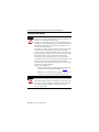
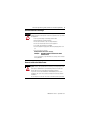
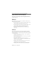
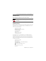
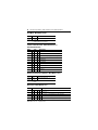
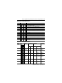
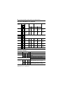
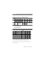
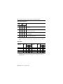
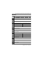
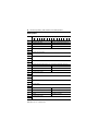
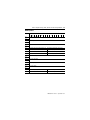
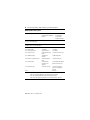
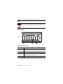
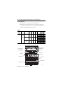
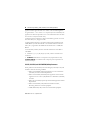
1
Installation Instructions
FLEX Ex 8 Input Analog, HART, and Noise Filter
Analog Modules
Catalog Numbers 1797-IE8, 1797-IE8H, 1797-IE8NF
Topic
Page
Important User Information
3
Environment and Enclosure
4
Prevent Electrostatic Discharge
5
Removal and Insertion Under Power
5
EMC Directive
6
Installation in Zone 1
7
Installation in Zone 22
7
Install the Module
8
Wire the Module to a 1797-TB3 or 1797-TB3S Terminal Base Unit
10
Ground the Module
12
Inputs
12
1797-IE8 and 1797-IE8NF Input Map (Read Words)
16
1797-IE8H Input Map (Read Words)
17
1797-IE8H Input Map (Read Words)
18
1797-IE8 and 1797-IE8NF Output Map (Write Words)
19
1797-IE8H Output Configuration Map
19
Fault Mode - Write Words 0 and 1
22
“Add-on” Filter Selections - Write Words 0 and 1 or Filter Cutoff Selections
22
2 FLEX Ex 8 Input Analog, HART, and Noise Filter Analog Modules
Topic
Page
Remote Transmitter Error Up/Down - Write Words 0 and 1
22
Data Format - Write Words 0 and 1
22
Data Format - Write Words 2 and 3
23
Error Level 0.1 mA Steps
24
1797-IE8H Secondary Master Enable (SME)/ Primary Master Inhibit (PMI)
25
Byte Order Configuration
26
Digital Filter
26
HART Input Data
30
HART Input Data Descriptions
34
HART Read Back Threshold
35
Square Root Threshold
35
Field Descriptions
27
Repair
36
Status Indicators
36
Specifications
37
Entity Parameters
41
Publication 1797-5.5 - September 2011
FLEX Ex 8 Input Analog, HART, and Noise Filter Analog Modules 3
Important User Information
Solid state equipment has operational characteristics differing from those of electromechanical
equipment. Safety Guidelines for the Application, Installation and Maintenance of Solid State Controls
(Publication SGI-1.1 available from your local Rockwell Automation sales office or online at
http://literature.rockwellautomation.com) describes some important differences between solid state
equipment and hard-wired electromechanical devices. Because of this difference, and also because of the
wide variety of uses for solid state equipment, all persons responsible for applying this equipment must
satisfy themselves that each intended application of this equipment is acceptable.
In no event will Rockwell Automation, Inc. be responsible or liable for indirect or consequential damages
resulting from the use or application of this equipment.
The examples and diagrams in this manual are included solely for illustrative purposes. Because of the
many variables and requirements associated with any particular installation, Rockwell Automation, Inc.
cannot assume responsibility or liability for actual use based on the examples and diagrams.
No patent liability is assumed by Rockwell Automation, Inc. with respect to use of information, circuits,
equipment, or software described in this manual.
Reproduction of the contents of this manual, in whole or in part, without written permission of Rockwell
Automation, Inc., is prohibited.
Throughout this manual, when necessary, we use notes to make you aware of safety considerations.
WARNING
IMPORTANT
ATTENTION
Identifies information about practices or circumstances that can cause an explosion in
a hazardous environment, which may lead to personal injury or death, property
damage, or economic loss.
Identifies information that is critical for successful application and understanding of
the product.
Identifies information about practices or circumstances that can lead to personal injury
or death, property damage, or economic loss. Attentions help you identify a hazard,
avoid a hazard, and recognize the consequences.
SHOCK HAZARD
Labels may be located on or inside the equipment (for example, drive or motor) to alert
people that dangerous voltage may be present.
BURN HAZARD
Labels may be located on or inside the equipment (for example, drive or motor) to alert
people that surfaces may be dangerous temperatures.
Publication 1797-5.5 - September 2011
4 FLEX Ex 8 Input Analog, HART, and Noise Filter Analog Modules
Environment and Enclosure
ATTENTION
This equipment is intended for use in a Pollution Degree 2 industrial
environment, in overvoltage Category II applications (as defined in IEC 60664-1),
at altitudes up to 2000 m (6562 ft) without derating.
This equipment is considered Group 1, Class A industrial equipment according
to IEC/CISPR 11. Without appropriate precautions, there may be difficulties with
electromagnetic compatibility in residential and other environments due to
conducted and radiated disturbances.
This equipment is supplied as open-type equipment. It must be mounted within
an enclosure that is suitably designed for those specific environmental
conditions that will be present and appropriately designed to prevent personal
injury resulting from accessibility to live parts. The enclosure must have suitable
flame-retardant properties to prevent or minimize the spread of flame,
complying with a flame spread rating of 5VA, V2, V1, V0 (or equivalent) if
non-metallic. The interior of the enclosure must be accessible only by the use of
a tool. Subsequent sections of this publication may contain additional
information regarding specific enclosure type ratings that are required to comply
with certain product safety certifications.
In addition to this publication, see:
• Industrial Automation Wiring and Grounding Guidelines, for additional
installation requirements, Allen-Bradley publication 1770-4.1.
• NEMA Standards 250 and IEC 60529, as applicable, for explanations of
the degrees of protection provided by different types of enclosure.
ATTENTION
This product is grounded through the DIN rail to chassis ground. Use zinc plated
yellow-chromate steel DIN rail to assure proper grounding. The use of other DIN
rail materials (for example, aluminum or plastic) that can corrode, oxidize, or are
poor conductors, can result in improper or intermittent grounding. Secure DIN
rail to mounting surface approximately every 200 mm (7.8 in.) and use
end-anchors appropriately.
Publication 1797-5.5 - September 2011
FLEX Ex 8 Input Analog, HART, and Noise Filter Analog Modules 5
Prevent Electrostatic Discharge
ATTENTION
This equipment is sensitive to electrostatic discharge, which can cause internal
damage and affect normal operation. Follow these guidelines when you handle
this equipment:
• Touch a grounded object to discharge potential static.
• Wear an approved grounding wriststrap.
• Do not touch connectors or pins on component boards.
• Do not touch circuit components inside the equipment.
• Use a static-safe workstation, if available.
• Store the equipment in appropriate static-safe packaging when not in
use.
• Post a sign near these modules:
Attention! Avoid electrostatic charging.
ATENÇÃO! PREVENIR CONTRA O ACÚMULO DE CARGA
ELETROSTÁTICA
For your convenience, a sign that can be cut out and posted is included
in this publication.
Removal and Insertion Under Power
WARNING
These modules are designed so you can remove and insert them under
power. However, take special care when removing or inserting modules in an
active process. I/O attached to any module being removed or inserted can
change states due to its input/output signal changing conditions.
If you insert or remove the terminal base while backplane power is on, an
electrical arc can occur. This could cause an explosion in hazardous location
installations.
Be sure that power is removed or the area is nonhazardous before proceeding.
Publication 1797-5.5 - September 2011
6 FLEX Ex 8 Input Analog, HART, and Noise Filter Analog Modules
European Communities (EC) Directive Compliance
If this product has the CE mark it is approved for installation within the
European Union and EEA regions. It has been designed and tested to meet
the following directives.
EMC Directive
These products are tested to meet the Council Directive 2004/108/EC by
applying the following standards:
• EN 61000-6-4:2007, Electromagnetic Compatibility (EMC) - Part 6-4:
Generic Standard for Industrial Environments (Class A)
• EN 61000-6-2:2005, Electromagnetic Compatibility (EMC) - Part 6-2:
Generic Standards - Immunity for Industrial Environments
• EN61326-1:2006 (Industrial), Electrical Equipment For
Measurement, Control, and Laboratory Use - Industrial EMC
Requirements
ATEX Directive
These products are tested in conjunction with associated I/O modules to
meet the Council Directive 94/9/EC (ATEX) Equipment and Protective
Systems Intended for Use in Potentially Explosive Atmospheres by applying
the following standards:
• EN60079-11:2007, Explosive atmospheres - Part 11 : equipment
protection by intrinsic safety "i"
• EN60079-0:2006, Electrical apparatus for explosive gas atmospheres Part 0 : general requirements
• EN 60079-26 : 2004, Electrical apparatus for explosive gas
atmospheres - Part 26 : construction, test and marking of Group II
Category 1 G electrical apparatus
• EN61241-0 : 2006, Electrical apparatus for use in the presence of
combustible dust - Part 0: General requirements
• EN61241-11:2006, Electrical apparatus for use in the presence of
combustible dust – Part 11: Protection by intrinsic safety 'iD'
Publication 1797-5.5 - September 2011
FLEX Ex 8 Input Analog, HART, and Noise Filter Analog Modules 7
Installation in Zone 1
These modules must not be exposed to the environment. Provide a suitable
metal enclosure. This module has a protection factor of IP20.
WARNING
These modules cannot be used in an intrinsically safe
environment after they have been exposed to non-intrinsically
safe signals.
Installation in Zone 22
When the module is installed in Zone 22, the following cabinets must be used:
IVK2-ISRPI-V16LC; IVK2-ISRPI-V8HYW; or IVK2-ISRPI-V8LC. These
cabinets can be purchased from:
Pepperl+Fuchs GmbH
Konigsberger Allee 85-87, D-68307
Mannheim, Germany
Attn: PA Sales Dept.
Kirsten Becker
Telephone +49 776 1298
www.pepperl-fuchs.com
The IS-RPI cabinets (type IVK2-ISRPI-V8LC, IVK2-ISRPI-V8HYW, or
IVK2-ISPRI-V16LC) ensures the basic protection for the intrinsically safe
apparatus of the FLEX Ex system for use in Zone 22. It corresponds with
category 3D according to RL 94/9 EG and with the type label marked with
the following information:
Pepperl+Fuchs GmbH
68307 Mannheim
IVK2-ISRPI-V8LC (or IVK2-ISRPI-V8HYW or
IVK2-ISRPI-V16LC)
II 3 D Ex tD A22 IP54 T70 °C X
CE
Serial (manufacturing) number
Model year
Publication 1797-5.5 - September 2011
8 FLEX Ex 8 Input Analog, HART, and Noise Filter Analog Modules
Install the Module
Read this for information about how to install the module which must be
used with a 1797-TB3 or 1797-TB3S intrinsically safe terminal base unit.
7
3
1
8
2
6
4
5
Label here or under here
ATTENTION
ATTENTION
40231
This equipmment is considered Group 1, Class A industrial equipement
according to IEC/CISPR Publication 11. Without appropriate precautions, there
may be potential difficulties ensuring electromagnetic compatibility in other
environments due to conducted as well as radiated disturbance.
This equipment is supplied as open-type equipment. It must be mounted within
an enclosure that is suitably designed for those specific environmental
conditions that will be present and appropriately designed to prevent personal
injury resulting from accessiblity to live parts. The interior of the enclosure must
be accessible only by the use of a tool. Subsequent sections of this publication
may contain additional infromation regarding specific enclosure type ratings
that are required to comply with certain productsafety certifications.
During mounting of all devices, be sure that all debris (such as metal chips or
wire strands) is kept from falling into the module. Debris that falls into the
module could cause damage on power up.
Publication 1797-5.5 - September 2011
FLEX Ex 8 Input Analog, HART, and Noise Filter Analog Modules 9
ATTENTION
Do not remove or replace a Terminal Base unit while power is applied.
Interruption of the backplane can result in unintentional operation or machine
motion.
To install the module on a 1797 terminal base, see the figure and complete the
following.
1. Rotate keyswitch (1) on terminal base unit (2) clockwise to position 3
(1797-IE8 and 1797-IE8NF) or position 8 (1797-IE8H) as required
for the particular type of module.
IMPORTANT
Do not change the position of the keyswitch after wiring the terminal base
unit.
2. Make certain the flexbus connector (3) is pushed all the way to the left
to connect with the neighboring terminal base/adapter.
IMPORTANT
You cannot install the module unless the connector is fully extended.
3. Make sure the pins on the bottom of the module are straight so they
align properly with the connector in the terminal base unit.
4. Position the module (4) with its alignment bar (5) aligned with the
groove (6) on the terminal base.
5. Press firmly and evenly to seat the module in the terminal base unit,
noting that the module is seated when the latching mechanism (7) is
locked into the module.
6. Remove cap plug (8) and attach another intrinsically safe terminal base
unit to the right of this terminal base unit if required.
IMPORTANT
Make certain that you only connect terminal base units to other intrinsically
safe system modules or adapters to maintain the integrity of the intrinsically
safe backplane.
Publication 1797-5.5 - September 2011
10 FLEX Ex 8 Input Analog, HART, and Noise Filter Analog Modules
41307
Wire the Module to a 1797-TB3 or 1797-TB3S Terminal Base Unit
WARNING
If you connect or disconnect wiring while the field-side power is on, an electrical
arc can occur. This could cause an explosion in hazardous location installations.
Be sure that power is removed or the area is nonhazardous before proceeding.
Module Wiring
0
1
2
3
4
5
6
7
8
9
10 11
12 13
14
15
Row A
16
+ sig -
+ sig -
+ sig -
Ch 0
Ch 1
Ch 2
17
18
19
20
21
22
23
24
25
26
+ sig Ch 3
27
28
29
30
31
32
33
48 49
50
Row B
+ sig -
+ sig -
Ch 4
34
35
Ch 5
36 37
38
39 40 41
+ sig -
+ sig -
Ch 6
42 43
Ch 7
44
45
46 47
51
Row C
+V -V
No connections allowed to terminals 16, 33, 36, 40, 41, 42, 43, 44, 45, and 49.
+V -V
40071
1. Connect the individual input wiring to (+) terminals (0, 4, 8, 12) on
the 0…15 row (A) and on the 16…33 row (B) (terminals 17, 21, 25,
29) as indicated in the table, Wire Connections on page 11.
2. Connect the associated input to the corresponding (sig) terminal (1, 5,
9, 13) on the 0…15 row (A), and on the 16…33 row (B) (terminals 18,
22, 26, 30) for each input as indicated in the table, Wire Connections
on page 11.
Publication 1797-5.5 - September 2011
FLEX Ex 8 Input Analog, HART, and Noise Filter Analog Modules 11
3. For other configurations, see the wiring diagrams in the section,
Inputs on page 12.
4. Connect +V DC power to terminal 34 on the 34…51 row (C).
5. Connect -V to terminal 35 on the 34…51 row (C).
WARNING
Make certain that you power these modules with an intrinsically safe power
supply. Do not exceed the values listed in the specifications for these modules.
If you connect or disconnect wiring while the field-side power is on, an electrical
arc can occur. This could cause an explosion in hazardous location installations.
Be sure that power is removed or the area is nonhazardous before proceeding.
6. If continuing power to the next terminal base unit, connect a jumper
from terminal 50 (+V) on this base unit to terminal 34 on the next
base unit.
7. If continuing common to the next terminal base unit, connect a
jumper from terminal 51 (-V) on this base unit to terminal 35 on the
next base unit.
ATTENTION
To reduce susceptibility to noise, power analog modules and digital modules
from separate power supplies.
Wire Connections
Input
Input
Source
Input
Signal
Input
Return
Input
Input
Source
Input
Signal
Input
Return
Input 0
A-0
A-1
A-2
Input 4
B-17
B-18
B-19
Input 1
A-4
A-5
A-6
Input 5
B-21
B-22
B-23
Input 2
A-8
A-9
A-10
Input 6
B-25
B-26
B-27
Input 3
A-12
A-13
A-14
Input 7
B-29
B-30
B-31
+V
Terminals 34 and 50
-V
Terminals 35 and 51
Publication 1797-5.5 - September 2011
12 FLEX Ex 8 Input Analog, HART, and Noise Filter Analog Modules
ATTENTION
Do not use the unused terminals on this terminal base unit. Using these
terminals as supporting terminals can result in damage to the module, or
unintended operation of your system, or both.
Ground the Module
All I/O wiring must use shielded wire. Shields must be terminated external to
the module, such as bus bars and shield-terminating feed throughs.
44862
Inputs
Each input can be operated from an analog field device signal. Do not apply
any nonintrinsically safe signals to these modules.
When using an intrinsically safe electrical apparatus according to EN50020,
the European Community directives and regulations must be followed.
The channels in these modules are electrically connected to each other and
have a common plus-line.
IMPORTANT
When interconnecting several lines, you must consider the total
accumulated power and check for intrinsic safety.
Publication 1797-5.5 - September 2011
FLEX Ex 8 Input Analog, HART, and Noise Filter Analog Modules 13
1797-IE8 and
1797-IE8NF
Flexbus
+V
-V
Bus
Isolated
4…20 mA
4…20 mA Power
Xmit
4…20 mA
Xmit
I
P
Xmit
I
+
273 Ω
21.5V
P
uC
Sig
22 Ω
I
-
P
40072
1797-IE8H
+V
-V
HART
Modem
Flexbus
Bus
273 Ω
23.7V
+
4…20 mA
Xmit
I
uC
P
4…20 mA
Xmit
I
P
Sig
10 Ω
-
43852
Publication 1797-5.5 - September 2011
14 FLEX Ex 8 Input Analog, HART, and Noise Filter Analog Modules
1797-IE8 and 1797-IE8NF Field Transmitter Supply Characteristic
The field transmitter supply can be modeled as a 21.5V source with a 273 Ω
series resistance. (See the following graph.) This provides a simple and useful
mechanism to determine transmitter and loop compatibility.
The actual transmitter supply contains three ranges of impedance with the
following characteristics:
• The output voltage is ≈ 21.5V for load currents of 0 mA.
• If the load is more than ≈ 680 Ω but less than ∞Ω, the transmitter
supply is in a constant resistance region (≈ 273 Ω).
• For load impedance between 0 and ≈ 680 Ω, the transmitter supply
current is in constant current mode (≈ 22 mA).
If an intrinsic safety fault occurs in the field transmitter supply of any channel,
every channel’s field transmitter power is shutdown.
The following graph depicts the typical transmitter load characteristic.
Voltage
22
20
18
V DC
16
14
12
10
8
6
4
2
0
0
5
10
15
mA
20
25
43002
The normal module field side power consumption is 7.5 W when all channel
21.5V sources (+) are loaded. If field devices are used that are powered
separately, the module field-side power consumption can be determined by
Field_Side_Power = 9.5V x (300 mA + n x 55 mA). Where n is the number of
field devices that are supplied by the 1797-IE8 or 1797-IE8NF.
Publication 1797-5.5 - September 2011
FLEX Ex 8 Input Analog, HART, and Noise Filter Analog Modules 15
1797-IE8H Field Transmitter Supply Characteristic
The field transmitter supply can be modeled as a 23.7V source with a 273 Ω
series resistance. (See the following graph.) This provides a simple and useful
mechanism to determine transmitter and loop compatibility.
The actual transmitter supply contains three ranges of impedance with the
following characteristics:
• The output voltage is ≈ 23.7V for load currents of 0 mA.
• If the load is more than ≈ 750 Ω but less than ∞Ω, the transmitter
supply is in a constant resistance region (≈ 273 Ω).
• For load impedance between 0 and ≈ 750 Ω, the transmitter supply
current is controlled by the field device to a maximum of ≈ 22 mA.
If an intrinsic safety fault occurs in the field transmitter supply of any channel,
every channel’s field transmitter power is shutdown.
The following graph depicts the typical transmitter load characteristic.
Voltage
24
23
V DC
17
16
15
14
3
2
1
0
0
4
8
12
mA
16
20
24
43850
The normal module field side power consumption is 7.1 W when all channel
23.7V sources (+) are loaded. If field devices are used that are powered
separately, the module field-side power consumption can be determined by
Field_Side_Power = 9.5V x (180 mA + n x 69 mA). Where n is the number of
field devices that are supplied by the 1797-IE8H.
Publication 1797-5.5 - September 2011
16 FLEX Ex 8 Input Analog, HART, and Noise Filter Analog Modules
1797-IE8 and 1797-IE8NF Input Map (Read Words)
Bit
Word
15
0
Channel 0 Input Data
14
13
12
11
10
1
Channel 1 Input Data
2
Channel 2 Input Data
3
Channel 3 Input Data
4
Channel 4 Input Data
5
Channel 5 Input Data
6
Channel 6 Input Data
7
Channel 7 Input Data
8
OA OA OA OA OA OA OA OA UA UA UA UA UA UA UA UA
Ch7 Ch6 Ch5 Ch4 Ch3 Ch2 Ch1 Ch0 Ch7 Ch6 Ch5 Ch4 Ch3 Ch2 Ch1 Ch0
9
RF RF RF RF RF RF RF RF LF LF LF LF LF LF LF LF
Ch7 Ch6 Ch5 Ch4 Ch3 Ch2 Ch1 Ch0 Ch7 Ch6 Ch5 Ch4 Ch3 Ch2 Ch1 Ch0
10
11
9
8
7
6
5
4
3
2
1
0
Diagnostic Status
Res Module command response
Flg
Where: Ch = channel
OA = Over Alarm
UA = Under Alarm
RF = Remote Fault
LF = Local Fault
Res Flg = Response Flag
Publication 1797-5.5 - September 2011
Module response data
FLEX Ex 8 Input Analog, HART, and Noise Filter Analog Modules 17
1797-IE8H Input Map (Read Words)
Bit
Word
15
0
Channel 0 Input Data
14
13
12
1
Channel 1 Input Data
2
Channel 2 Input Data
3
Channel 3 Input Data
4
Channel 4 Input Data
5
Channel 5 Input Data
6
Channel 6 Input Data
7
Channel 7 Input Data
8
OA OA OA OA OA OA OA OA UA UA UA UA UA UA UA UA
Ch7 Ch6 Ch5 Ch4 Ch3 Ch2 Ch1 Ch0 Ch7 Ch6 Ch5 Ch4 Ch3 Ch2 Ch1 Ch0
9
RF RF RF RF RF RF RF RF LF LF LF LF LF LF LF LF
Ch7 Ch6 Ch5 Ch4 Ch3 Ch2 Ch1 Ch0 Ch7 Ch6 Ch5 Ch4 Ch3 Ch2 Ch1 Ch0
10
Reserved
11
H Rb H Rb H Rb H Rb H Rb H Rb H Rb H Rb H H H H H H H H
Ch7 Ch6 Ch5 Ch4 Ch3 Ch2 Ch1 Ch0 Fail Fail Fail Fail Fail Fail Fail Fail
Ch7 Ch6 Ch5 Ch4 Ch3 Ch2 Ch1 Ch0
12
H H H H H H H H H H H H H H H H
Tmt Tmt Tmt Tmt Tmt Tmt Tmt Tmt Cm Cm Cm Cm Cm Cm Cm Cm
Ch7 Ch6 Ch5 Ch4 Ch3 Ch2 Ch1 Ch0 Ch7 Ch6 Ch5 Ch4 Ch3 Ch2 Ch1 Ch0
Where: Ch = channel
OA = Over Alarm
UA = Under Alarm
RF = Remote Fault
LF = Local Fault
11
10
9
8
7
6
5
4
H Reserved
Rbd
3
2
1
0
Diagnostic Status
H Rbd = HART Rebuild
H Rb = HART Readback
H Fail = HART Failure
H Tmt = HART Transmitter
H Cm = HART Communication
Publication 1797-5.5 - September 2011
18 FLEX Ex 8 Input Analog, HART, and Noise Filter Analog Modules
1797-IE8H Input Map (Read Words)
Word
Bit
0
Input Data Channel 0
1
Input Data Channel 1
2
Input Data Channel 2
3
Input Data Channel 3
4
Input Data Channel 4
5
Input Data Channel 5
6
Input Data Channel 6
7
Input Data Channel 7
8
HA HA HA HA HA HA HA HA LA LA LA LA LA LA LA LA
Ch 7 Ch 6 Ch 5 Ch 4 Ch 3 Ch 2 Ch 1 Ch 0 Ch 7 Ch 6 Ch 5 Ch 4 Ch 3 Ch 2 Ch 1 Ch 0
9
SA
SA SA SA SA SA SA SA
Rem. Rem. Rem. Rem. Rem. Rem. Rem. Rem.
Ch 7 Ch 6 Ch 5 Ch 4 Ch 3 Ch 2 Ch 1 Ch 0
OR OR OR OR OR OR OR OR
Ch7 Ch6 Ch5 Ch4 Ch3 Ch2 Ch1 Ch0
10
Reserved
HR Reserved
11
HCF HCF HCF HCF HCF HCF HCF HCF HF HF HF HF HF HF HF HF
Ch 7 Ch 6 Ch 5 Ch 4 Ch 3 Ch 2 Ch 1 Ch 0 Ch 7 Ch 6 Ch 5 Ch 4 Ch 3 Ch 2 Ch 1 Ch 0
12
HP HP HP HP HP HP HP HP HC HC HC HC HC HC HC HC
Ch 7 Ch 6 Ch 5 Ch 4 Ch 3 Ch 2 Ch 1 Ch 0 Ch 7 Ch 6 Ch 5 Ch 4 Ch 3 Ch 2 Ch 1 Ch 0
15
14
13
12
11
10
Where: HA = high alarm
LA = low alarm
SA = second alarm
OR = out of range
Res. = reserved
HR = HART rebuilding
HCF = HART current fault
HF = HART communication fault
HP = HART present
HC = HART communication
Publication 1797-5.5 - September 2011
9
8
7
6
5
4
3
2
1
0
Diagnostic Status
FLEX Ex 8 Input Analog, HART, and Noise Filter Analog Modules 19
1797-IE8 and 1797-IE8NF Output Map (Write Words)
Bit
Word 15
14
13
12
11
10
9
8
7
6
5
4
3
2
1
0
0
Reserved High and Low Error Level
0…3
u/d Filter Cutoff
0…3 0…3
Data Format
0…3
Flt
Md
0…3
1
Sq Rt Th
u/d Filter Cutoff
4…7 4…7
Data Format
4…7
Flt
Md
4…7
2
CF
High and Low Error Level
4…7
Module Command
Module Command Data
Where: u/d = Up/Down
Flt Md = Fault Module
Sq Rt Th = Square Root Threshold
CF = Command Flag
1797-IE8H Output Configuration Map
Bit
Word 15
14
13
12
11
10
9
8
7
6
5
4
3
2
1
0
0
Reserved High and Low Error Level
0…3
u/d Filter Cutoff
0…3 0…3
Data Format
0…3
Flt
Md
0…3
1
Sq Rt Th
u/d Filter Cutoff
4…7 4…7
Data Format
4…7
Flt
Md
4…7
High and Low Error Level
4…7
Where: u/d = Up/Down
Flt Md = Fault Module
Sq Rt Th = Square Root Threshold
Publication 1797-5.5 - September 2011
20 FLEX Ex 8 Input Analog, HART, and Noise Filter Analog Modules
1797-IE8H Configuration Map
Word Bit
15
14
13 12 11 10 9
8
7
6
5
4
3
2
1
0
0
NF VR FE FE FE FE Byte
Ch7 Ch6 Ch5 Ch4 Order
HS HSI FE FE FE FE Byte
LEDs
Ch3 Ch2 Ch1 Ch0 Order
1
HD HD HD HD HD HD HD HD HHE HHE HHE HHE HHE HHE HHE HHE
Ch7 Ch6 Ch5 Ch4 Ch3 Ch2 Ch1 Ch0 Ch7 Ch6 Ch5 Ch4 Ch3 Ch2 Ch1 Ch0
2
Data Format Ch3
Data Format Ch2
Data Format Ch1
Data Format Ch0
3
Data Format Ch7
Data Format Ch6
Data Format Ch5
Data Format Ch4
4
HART Read Back
Threshold Ch1
Digital Filter
Ch1
HART Read Back
Threshold Ch0
Digital Filter
Ch0
5
HART Read Back
Threshold Ch3
Digital Filter
Ch3
HART Read Back
Threshold Ch2
Digital Filter
Ch2
6
HART Read Back
Threshold Ch5
Digital Filter
Ch5
HART Read Back
Threshold Ch4
Digital Filter
Ch4
7
HART Read Back
Threshold Ch7
Digital Filter
Ch7
HART Read Back
Threshold Ch6
Digital Filter
Ch6
8
Square
root
Limit
Ch7
9
High Alarm Limit Ch0
Group B(1)
Square
root
Limit
Ch6
Square
root
Limit
Ch5
Square
root
Limit
Ch4
10
Low Alarm Limit Ch0
11
High High Alarm Limit (Remote) Ch0
12
Low Low Alarm Limit (Remote) Ch0
13
High Alarm Limit Ch1
14
Low Alarm Limit Ch1
15
High High Alarm Limit (Remote) Ch1
16
Low Low Alarm Limit (Remote) Ch1
17
High Alarm Limit Ch2
18
Low Alarm Limit Ch2
19
High High Alarm Limit (Remote) Ch2
20
Low Low Alarm Limit (Remote) Ch2
21
High Alarm Limit Ch3
Publication 1797-5.5 - September 2011
Group A(1)
Square
root
Limit
Ch3
Square
root
Limit
Ch2
Square
root
Limit
Ch1
Square
root
Limit
Ch0
FLEX Ex 8 Input Analog, HART, and Noise Filter Analog Modules 21
1797-IE8H Configuration Map
Word Bit
15
14
13 12 11 10 9
22
Low Alarm Limit Ch3
23
High High Alarm Limit (Remote) Ch3
24
Low Low Alarm Limit (Remote) Ch3
25
High Alarm Limit Ch4
26
Low Alarm Limit Ch4
27
High High Alarm Limit (Remote) Ch4
28
Low Low Alarm Limit (Remote) Ch4
29
High Alarm Limit Ch5
30
Low Alarm Limit Ch5
31
High High Alarm Limit (Remote) Ch5
32
Low Low Alarm Limit (Remote) Ch5
33
High Alarm Limit Ch6
34
Low Alarm Limit Ch6
35
High High Alarm Limit (Remote) Ch6
36
Low Low Alarm Limit (Remote) Ch6
37
High Alarm Limit Ch7
8
7
6
5
4
3
2
1
0
38
Low Alarm Limit Ch7
39
High High Alarm Limit (Remote) Ch7
40
Low Low Alarm Limit (Remote) Ch7
41
HR HR HR HR HR HR HR HR HCD HCD HCD HCD HCD HCD HCD HCD
Ch7 Ch6 Ch5 Ch4 Ch3 Ch2 Ch1 Ch0 Ch7 Ch6 Ch5 Ch4 Ch3 Ch2 Ch1 Ch0
Where
(1)
NF: notch filter (50/60 Hz)
FE: fault enable
HS LED: HART status LEDs
HD: HART disable
HR: HART rebuild
HCD: HART CMD3 disable
VR: verify replacement
HSI: HART status inhibit
HHE: HART handheld enable
Group B and Group A “Not used in some controller software”
Publication 1797-5.5 - September 2011
22 FLEX Ex 8 Input Analog, HART, and Noise Filter Analog Modules
Fault Mode - Write Words 0 and 1
Word 0 Bit 00
Fault enable for Channels 0...3
Word 1 Bit 00
Fault enable for Channels 4...7
Where: O = disable
1 = enable with wire-off overload
“Add-on” Filter Selections - Write Words 0 and 1 or
Filter Cutoff Selections
Word
Bits
Description
0
07
06
05
Channels 0...3
1
07
06
05
Channels 4...7
0
0
0
Hardware filtering only (default filtering)
0
0
1
40 Hz (25 ms)
0
1
0
20 Hz (50 ms)
0
1
1
10 Hz (100 ms)
1
0
0
4 Hz (250 ms)
1
0
1
2 Hz (500 ms)
1
1
0
1 Hz (1 s)
1
1
1
0.5 Hz (2 s)
Remote Transmitter Error Up/Down - Write Words 0 and 1
Word 0 Bit 08
Up/down for Channels 0...3
Word 1 Bit 08
Up/down for Channels 4...7
Where: O = up
1 = down
Data Format - Write Words 0 and 1
Word
Description
Bits
0
04
03
02
01
Channels 0...3
1
04
03
02
01
Channels 4...7
0
0
0
0
0…22 mA = 0...22,000 with error steps (default)
0
0
0
1
0…22 mA = 0…110%, with error steps
0
0
1
0
0…22 mA = 0…104.8%, square root, with error steps
Publication 1797-5.5 - September 2011
FLEX Ex 8 Input Analog, HART, and Noise Filter Analog Modules 23
Data Format - Write Words 0 and 1
Word
Description
Bits
0
0
1
1
0…22 mA = 0…65,535, unsigned integer, with error steps
0
1
0
0
2…22 mA, with error steps
0
1
0
1
2…22 mA = -12.5…112.5%, with error steps
0
1
1
0
4…22 mA = 0…106%, square root, with error steps
0
1
1
1
4…20 mA = 0…65,535, unsigned integer, with error steps
1
0
0
0
Not assigned
1
0
0
1
Not assigned
1
0
1
0
Not assigned
1
0
1
1
0…22 mA = A/D count, with fixed error
1
1
0
0
3.6…21 mA = NAMUR NE 43, with fixed error
1
1
0
1
3…21 mA = -6.25…106.25% with fixed error
1
1
1
0
2…22 mA = -12.5…112.5% with fixed error
1
1
1
1
Not assigned
Data Format - Write Words 2 and 3
Data
Format
Bits
15
11
7
3
14
10
6
2
Format
13
9
5
1
12
8
4
0
Signal Range User Range
LO
HI
LO
Resolution
HI
0
0 0 0 0 0…20 mA as 0.00
Milliamps
22.00
0
22000
0.1% of
(0.000 mA) (22.000 mA) 0...20 mA
1
0 0 0 1 0…20 mA as 0.00
%
22.00
0
(0%)
11000
(110.00%)
0.2% of
0...20 mA
2
0 0 1 0 0…20 mA as 0.00
⎟%
22.00
0
(0%)
10488
(140.88%)
0.19% of
0...20 mA
3
0 0 1 1 0…20 mA as 0.00
unsigned
integer
20.00
0
65535
0.03% of
(0.000 mA) (20.000 mA) 0...20 mA
4
0 1 0 0 4…20 mA as 2.00
mA
22.00
2000
22000
0.01% of
(2.000 mA) (22.000 mA) 4...20 mA
5
0 1 0 1 4…20 mA as 2.00
%
22.00
-1250
11250
(-12.50%) (112.50%)
0.16% of
4...20 mA
Publication 1797-5.5 - September 2011
24 FLEX Ex 8 Input Analog, HART, and Noise Filter Analog Modules
Data Format - Write Words 2 and 3 (Continued)
Data
Format
Bits
15
11
7
3
14
10
6
2
Format
13
9
5
1
Signal Range User Range
12
8
4
0
LO
HI
LO
HI
Resolution
6
0 1 1 0 4…20 mA as 4.00
⎟%
22.00
0
(0%)
10607
(106.07%)
0.17% of
4...20 mA
7
0 1 1 1 4…20 mA as 4.00
unsigned
integer
20.00
0
(4 mA)
65535
(20 mA)
0.03% of
4...20 mA
8
1 0 0 0 Not assigned
9
1 0 0 1
10
1 0 1 0
11
1 0 1 1 0...20 mA as 0.00
A/D count
22.00
0
(0 mA)
55000
(22 mA)
0.04% of
0...20 mA
12
1 1 0 0 4...20 mA as 3.60
%
21.00
-250
(-2.50%)
10625
(106.25%)
0.16% of
4...20 mA
13
1 1 0 1 4...20 mA as 3.00
%
21.00
-625
(-6.25%)
10625
(106.25%)
0.16% of
4...20 mA
14
1 1 1 0 4...20 mA as 2.00
%
22.00
-1250
11250
(-12.50%) (112.50%)
0.16% of
4...20 mA
15
1 1 1 1 Not assigned
Error Level 0.1 mA Steps
Word
Bits
Description
Word 0
13
12
11
10
09
Word 1
13
12
11
10
09
Error level channels 0...3
Error level channels 4...7
0
0
0
0
0
Disabled
0.1 mA * binary valve = remote fault alarm
Examples
Data Format 0
2...22 mA
-12.5...112.5% 0
0
1
1
1
Binary value = 7, 0.1 mA * 7 = 0.7 mA
Remote fault alarm at -4.38% or +104.38%
1
1
1
1
Binary value = 15, 0.1 mA * 15 = 1.5 mA
Remote fault alarm at -9.38% or + 109.38%
Publication 1797-5.5 - September 2011
FLEX Ex 8 Input Analog, HART, and Noise Filter Analog Modules 25
1797-IE8H Analog Input Extended Configuration Data Table
Config Bits
Word 15 14 13 12 11 10 9
8
7
6
5
4
3
2
1
0
0
PMI PMI PMI PMI PMI PMI PMI PMI SME SME SME SME SME SME SME SME
Ch Ch Ch Ch Ch Ch Ch Ch Ch 7 Ch 6 Ch 5 Ch 4 Ch 3 Ch 2 Ch 1 Ch 0
7 6 5 4 3 2 1 0
1
Reserved
HS HS 50/ HART Read Back Threshold
LED Inht 60 Ch 0...3
Hz
HART Read Back
Threshold Ch 4...7
Where Ch = channel
PMI = primary master inhibit
SME = secondary master enable
HS LED = HART status LEDs
HS Inht = HART status inhibit
1797-IE8H Secondary Master Enable (SME)/ Primary Master Inhibit (PMI)
Bits(1)
1 (Default)
2
3
4
1
PMI
8, 9, 10, 11, 12, 13, 14, 15 0
0
1
SME
0, 1, 2, 3, 4, 5, 6, 7
0
1
0
1
Pulsed
On
Off
On
HART Smooth Filter
Rebuild
On
On
Off
Off
HART Read Back
On
On
Off
Off
Primary Master
On
On
Off
Off
Secondary Master
Off
On
Off
On
(1)
Where:
Ch 0 - bits 0 and 8; Ch 1 - bits 1 and 9; Ch 2 - bits 2 and 10; Ch 3 - bits 3 and 11
Ch 4 - bits 4 and 12; Ch 5 - bits 5 and 13; Ch 6 - bits 6 and 14; Ch 7 - bits 7 and 15
These two bits control a few module internal functions individually for
channels 0 through 7.
Publication 1797-5.5 - September 2011
26 FLEX Ex 8 Input Analog, HART, and Noise Filter Analog Modules
Byte Order Configuration
Byte Order Byte Order Description(1)
Group B
Group A
Bit 9 Bit 8 Bit 1 Bit 0
0
0
0
0
Little Endian Format (Default) = All data entries in true Little
Endian format.
1
0
1
0
Word Swap = Word swap only values requiring more then one
word,
for example: 32 bit float values.
0
1
0
1
Byte Swap (reserved for future implementation) = Byte swap all
words in data table.
1
1
1
1
Big Endian Format (reserved for future implementation) = All data
entries in true Big Endian format.
(1)
All other combinations are invalid. Values will Revert to the last valid configuration (in case of original
start-up this would be default configuration) and set module Diagnostic Status to "2" configuration
failure.
Digital Filter
Digital Filter
frequency
Decimal Bits
Value 2
1
0
10
9
8
Digital Filter
frequency
Decimal Bits
Value 2
1
0
10
9
8
0.5 Hz
7
0
0
0
10 Hz
3
1
0
0
1 Hz
6
0
0
1
Not applicable(1) 2
1
0
1
2 Hz
5
0
1
0
Not applicable
1
1
1
0
4 Hz
4
0
1
1
Not applicable
0
1
1
1
(1)
Decimal Values 2, 1 and 0 are not applicable. Values will Revert to the last valid configuration (in case
of original start-up this would be default configuration) and set module Diagnostic Status to "2"
configuration failure.
Publication 1797-5.5 - September 2011
FLEX Ex 8 Input Analog, HART, and Noise Filter Analog Modules 27
Field Descriptions
Analog Input Data
Specifies the value of the analog input data from the module. Specific
format is controlled by Module Data Format Control parameter. This
data is used when the channel is in analog input mode.
Overrange Alarm
Alarm signal for input overrange. This signal is always active.
Range: 0 = normal, 1 = input overrange
Underrange Alarm
Alarm signal for input underrange. This signal is always active.
Range: 0 = normal, 1 = input underrange
Remote Fault Alarm Alarm from remote transmitter, indicating transmitter difficulties,
sensor difficulties, or loop to the sensor is open. If not using a remote
transmitter, this alarm can be used as a high-high or low-low alarm.
Depending on Data Format, these current values may be indicated by
percent, mA, or integer values.
Range: 0 = normal, 1 = fault detected
Local Fault Alarm
Alarm indicating the loop to the transmitter, or, if there is no transmitter,
the loop is open or shorted. When active, this alarm triggers at 2 mA
and 22 mA for open and short respectively. Depending on Data Format,
these current values may be indicated by percent, mA, or integer
values.
Range: 0 = normal, 1 = fault detected
HART Rebuild Bit
(1797-IE8H)
The HART Rebuild bit will trigger a HART Rebuild on a transition from 0
to 1. The HART Rebuild bit must remain 1 for HART communications to
function after the rebuild completes. If the HART Rebuild bit is set to 0,
HART communications are disabled.
HART Rebuild Flag During the time the system is rebuilding the HART table, the HART
(1797-IE8H)
rebuild flag is set.
Range: 0 = normal, 1 = HART rebuilding
HART Failure
(1797-IE8H)
A 1 indicates that HART communications are failing on the associated
channel.
Range: 0 = normal, 1 = HART communication failure
HART
When this bit is set (1), it indicates that HART communications are
Communication
failing on the associated channel.
Fault (1797-IE8H??) Range: 0 = normal, 1 = HART communication fault
Publication 1797-5.5 - September 2011
28 FLEX Ex 8 Input Analog, HART, and Noise Filter Analog Modules
Field Descriptions
HART Read Back
(1797-IE8H)
The HART Read Back bits show deviations between the analog
measured current value on a loop (by the 1797-IE8H) and the digital real
current (sensed by the HART device on its own) received by the
1797-IE8H during HART communication in the background. This
functionality can be turned on by defining a HART Readback Threshold
greater than 0. See 1797-IE8H CE, CENELEC I/O Entity Parameters on
page 42. This functionality is used to recognize loop errors whereby a
parasitic current is bypassing the 1797-IE8H.
Range: 0 = normal, 1 = HART Readback threshold is exceeded.
HART Read Back
Threshold
(1797-IE8H)
Delivers the percentage value (in steps of 1%) of the threshold for
forcing the HART read back indication (input signal deviation
HART/Analog) with a 31% maximum deviation.
If there is no HART transmitter on the loop or the loop is not in the
transmitter list, the function is switched off internally in the I/O module.
Range: 0 = disabled, 1…4 = not supported from I/O module (set to 5
internally), 5…31 = percentage threshold data (5…31%).
HART
Communication
(1797-IE8H)
Range: 0 = normal, 1 = HART communication is currently occurring.
HART Transmitter
List (1797-IE8H)
When this bit is set (1), it indicates that a HART field device was found
during the rebuild sequence on the associated channel.
Range: 0 = transmitter was not found, 1 = HART transmitter was found.
Square Root
Threshold
(1797-IE8H)
This setting affects all channels using Data Format 2 or 6. It sets low,
end-of-scale percent value at which square roots start being reported.
Below this level 0% is reported. This compensates for asymptotic
values of the square-root function as the input approaches 0.
Range: 0 = disabled, 1 = 2%, 2 = 5%, 3 = 10%
Extended
Configuration
(1797-IE8H)
Configuration additions are needed for HART communications in Series
A mode. An extended configuration area is provided. This Extended
Configuration table is configured by writing a CIO or MSG instruction
with the following:
Class = 0x7D
Instance = Product location on flexbus (Use 1 for the module
located next to the adapter.)
Attribute = 0x65
Service = Set Attribute Single (0x10)
See 1797-IE8H CE, CENELEC I/O Entity Parameters on page 42.
Publication 1797-5.5 - September 2011
FLEX Ex 8 Input Analog, HART, and Noise Filter Analog Modules 29
Field Descriptions
HART Status
Indicators
When this bit is set (1), the status indicators are used for HART
diagnostic. Indicator behavior changes to show communication on
HART. Each indicator represents a HART loop. Flashing yellow indicates
that communication is currently being processed. Solid yellow means
that this device is in the transmitter list.
HART Status Inhibit When this bit is set (1), the HART communication status is not shown in
the realtime data table. The appropriate areas are cleared with zeroes.
Range: 0 = normal, 1 = inhibit HART
50/60 Hz Filter
Range: 0 = 50 Hz, 1 = 60 Hz
Publication 1797-5.5 - September 2011
30 FLEX Ex 8 Input Analog, HART, and Noise Filter Analog Modules
Cyclic HART Input Data
The HART input data holds the primary variables for the "live" HART
device, and other information gathered during the normal HART scan.
Additional "documentary" data is available through the pass through message
interface in the device information tables. Pass through messages are defined
in detail in the User Manual.
IMPORTANT
The HART Input Data for a channel may be zeroes if HART communications is
disabled for that channel. For more information on disabling HART
communications, refer to the Disable HART communications and HART
Disable functions in the Configuration Map table.
HART Input Data
Word
Bit
15
14
0
Reserved
1
Reserved
13
12
11
10
9
8
7
6
5
4
3
2
1
(HART Communications Status)
2
Ch0 HART Field Device Status
Ch0 HART Comm Status
3
Reserved
Ch0 HART Loop Status
4
Ch0 HART Primary Value
(IEEE 754-1985 Single-Precision 32 bit floating point)
5
6
7
8
9
10
11
Ch0 HART Secondary Value
(IEEE 754-1985 Single-Precision 32 bit floating point)
Ch0 HART Tertiary Value
(IEEE 754-1985 Single-Precision 32 bit floating point)
Ch0 HART Fourth (Quaternary) Value
(IEEE 754-1985 Single-Precision 32 bit floating point)
12
Ch0 Secondary Value Units Code
Ch0 Primary Value Units Code
13
Ch0 Fourth Value Units Code
Ch0 Tertiary Value Units Code
14
Ch1 HART Field Device Status
Ch1 HART Communication Status
15
Reserved
Ch1 HART Loop Status
16
Ch1 HART Primary Value
17
Publication 1797-5.5 - September 2011
0
Ch7 Ch6 Ch5 Ch4 Ch3 Ch2 Ch1 Ch0
FLEX Ex 8 Input Analog, HART, and Noise Filter Analog Modules 31
HART Input Data
Word
Bit
15
18
14
13
12
11
10
9
8
7
6
5
4
3
2
1
0
Ch1 HART Secondary Value
19
20
Ch1 HART Teritiary Value
21
22
Ch1 HART Fourth Value
23
24
Ch1 HART Secondary Value Units Code
Ch1 HART Primary Value Units Code
25
Ch1 HART Fourth Value
Ch1 HART Tertiary Value Units Code
26
Ch2 HART Field Device Status
Ch2 HART Communication Status
27
Reserved
Ch2 HART Loop Status
28
Ch2 HART Primary Value
29
30
Ch2 HART Secondary Value
31
32
Ch 2 HART Tertiary Value
33
34
Ch2 HART Fourth Value
35
36
Ch2 HART Secondary Value Units Code
Ch2 HART Primary Value Units Code
37
Ch2 HART Fourth Value
Ch2 HART Tertiary Value Units Code
38
Ch3 HART Field Device Status
Ch3 HART Communication Status
39
Reserved
Ch0 HART Loop Status
40
Ch3 HART Primary Value
41
42
Ch3 HART Secondary Value
43
44
Ch3 HART Tertiary Value
45
46
Ch3 HART Fourth Value
47
Publication 1797-5.5 - September 2011
32 FLEX Ex 8 Input Analog, HART, and Noise Filter Analog Modules
HART Input Data
Word
Bit
15
48
14
13
12
11
10
9
8
7
6
5
4
3
2
1
Ch3 HART Secondary Value Units Code
Ch3 HART Primary Value Units Code
49
Ch3 HART Fourth Value
Ch3 HART Tertiary Value Units Code
50
Ch4 HART Field Device Status
Ch4 HART Communication Status
51
Reserved
Ch4 HART Loop Status
52
Ch4 HART Primary Value
53
54
Ch4 HART Secondary Value
55
56
Ch4 HART Tertiary Value
57
58
Ch4 HART Fourth Value
59
60
Ch4 HART Secondary Value Units Code
Ch4 HART Primary Value Units Code
61
Ch4 HART Fourth Value
Ch4 HART Tertiary Value Units Code
62
Ch5 HART Field Device Status
Ch5 HART Communication Status
63
Reserved
Ch5 HART Loop Status
64
Ch5 HART Primary Value
65
66
Ch5 Secondary Value
67
68
Ch5 Tertiary Value
69
70
Ch5 Fourth Value
71
72
Ch5 HART Secondary Value Units Code
Ch5 HART Primary Value Units Code
73
Ch5 HART Fourth Value
Ch5 HART Tertiary Value Units Code
74
Ch6 HART Field Device Status
CH6 HART Communication Status
75
Reserved
Ch6 HART Loop Status
76
Ch6 HART Primary Value
77
Publication 1797-5.5 - September 2011
0
FLEX Ex 8 Input Analog, HART, and Noise Filter Analog Modules 33
HART Input Data
Word
Bit
15
78
14
13
12
11
10
9
8
7
6
5
4
3
2
1
0
Ch6 Secondary Value
79
80
Ch6 Tertiary Value
81
82
Ch6 Fourth Value
83
84
Ch6 HART Secondary Value Units Code
Ch6 HART Primary Value Units Code
85
Ch6 HART Fourth Value
Ch6 HART Tertiary Value Units Code
86
Ch7 HART Field Device Status
CH7 HART Communication Status
87
Reserved
Ch7 HART Loop Status
88
Ch7 HART Primary Value
89
90
Ch7 Secondary Value
91
92
Ch7 Tertiary Value
93
94
Ch7 Fourth Value
95
96
Ch7 HART Secondary Value Units Code
Ch7 HART Primary Value Units Code
97
Ch7 HART Fourth Value
Ch7 HART Tertiary Value Units Code
Publication 1797-5.5 - September 2011
34 FLEX Ex 8 Input Analog, HART, and Noise Filter Analog Modules
HART Input Data Descriptions
CHn: HART Communication Status
0: HART CMD3
Communication Disabled or
No Error
CHn: HART Comm Status (HART CMD3
Response first status byte):
Refer to User Manual
CHn: HART Field Device Status (HART
CMD3 Response second status byte):
Refer to User Manual
Chn: HART Loop Status:
Bit 0: HART enable
Bit 1: Device Connected
Bit 2: Response Error
Bit 3: CMD 48 Update
Bit 4: HART Loop Tolerance Error
Bit 5: HART Update
Bit 6: HART message
0: Disabled
0: Not Connected
0: No HART message
failure
0: CMD 48 not
updated
0: No HART Current
Fault
0: HART Device
information not
updated
0: No new message
Bit 7:
Where
1: HART CMD3
Communication
Error between
Adapter & Module
1: Enabled
1: Connected
1: Response ended in error
1: CMD 48 updated
1:HART Current Fault
1: HART Device information
updated since last read
1: HART user message
queue has completed a
message
Reserved
PVA = The primary variable for this channel has been acquired.
SVA = The secondary variable for this channel has been acquired.
TVA = The tertiary variable for this channel has been acquired.
FVA = The fourth (quaternary) variable for this channel has been acquired.
Publication 1797-5.5 - September 2011
FLEX Ex 8 Input Analog, HART, and Noise Filter Analog Modules 35
HART Read Back Threshold
HART Read Back
Decimal
Value
Bits
7
6
5
4
15
14
13
12
3
11
Disabled
0
0
0
0
0
0
Not applicable(1)
1
0
0
0
0
1
Not applicable
2
0
0
0
1
0
Not applicable
3
0
0
0
1
1
Not applicable
4
0
0
1
0
0
5%
5
0
0
1
0
1
6%
6
0
0
1
1
0
7%
7
0
0
1
1
1
8%
8
0
1
0
0
0
9%
9
0
1
0
0
1
10%
10
0
1
0
1
0
…
…
…
…
…
…
…
30%
30
1
1
1
1
0
31%
31
1
1
1
1
1
(1)
1, 2, 3, and 4 are not applicable. Values between 1 and 4 will lead the IOM to automatically use
an internal value of 5%.
Square Root Threshold
Square Root Limit
Disabled
2%
5%
10%
Decimal Value
0
1
2
3
Bits
1
3
5
7
9
11
13
15
0
0
1
1
0
2
4
6
8
10
12
14
0
1
0
1
Channel
Ch0
Ch1
Ch2
Ch3
Ch4
Ch5
Ch6
Ch7
Publication 1797-5.5 - September 2011
36 FLEX Ex 8 Input Analog, HART, and Noise Filter Analog Modules
Repair
ATTENTION
This module is not field repairable. Any attempt to open the module will void the
warranty and IS certification. If repair is necessary, return the module to the
factory.
Status Indicators
1797-IE8
shown
42054
Interpret the Status Indicators
Status
Description
Flashing red
Channel fault Channel 0 indicator will turn red while power-up check is running
Solid green
Power applied to module
Flashing green
No Flexbus communication Adapter not powered or faulty connnection
Solid yellow
HART communication functioning normally
Publication 1797-5.5 - September 2011
FLEX Ex 8 Input Analog, HART, and Noise Filter Analog Modules 37
Specifications
Specifications - 1797-IE8 and -IE8NF
Number of Inputs
8 single-ended, non-isolated
IS input type
Ex ia IIB/IIC T4
AEx ia IIC T4
Class I, II, III Division 1 Group A-G T4
IS module type
Ex ib IIB/IIC T4
AEx ib IIC T4
Class I, II, III Division 1 Groups A-D T4
Resolution
16 bits
Transfer Characteristics
Accuracy at 20 °C (68 °F) 0.1% of output signal range
Temperature Drift
0.05%/C of output signal range
Functional Data Range
>15V @ 22 mA
>21.5V @ 0 mA
Data Format
Configurable
Step Response to
4 ms (1797-IE8)
99% of FS
80 ms (1797-IE8NF)
Module from Adapter
Best/Worst Update Time 200 ms/1600 µs
Indicators
8 red fault indicators
1 green power indicator
Inputs (Intrinsically Safe) Uo < 23.7V
(Terminals: 0…2; 4…6; Io < 93.5 mA
8…10; 12…14; 17…19; P < 555 mW
o
21…23; 25…27; 29…31)
Publication 1797-5.5 - September 2011
38 FLEX Ex 8 Input Analog, HART, and Noise Filter Analog Modules
Specification 1797-IE8 and -IE8NF (Continued)
Isolation Path
Isolation Type
Input to Power Supply
Galvanic to DIN EN60079-11
Input to Flexbus
Galvanic to DIN EN60079-11
Input to Input
None
Power Supply to
Galvanic to DIN EN60079-11
Flexbus
Power Supply
Ui < 9.5V dc
(+V, -V Intrinsically Safe) Ii < 1 A
(Terminals: 34 and 50 (+): L = Negligible
i
35 and 51 (-))
Ci = Negligible
Module Field-side Power 7.5 W
Consumption
Power Dissipation
5.2 W
Thermal Dissipation
17.75 BTU/hr
Module Location
Cat. No. 1797-TB3 or 1797-TB3S
Conductor Wire Size
4mm2 (12 AWG) stranded max
Dimensions
Metric
Imperial
1.2 mm (3/64 in.) insulation max
46 mm x 94 mm x 75 mm
(1.8 in. x 3.7 in. x 2.95 in.)
200 g (approximately)
3
Weight
Keyswitch Position
Environmental Conditions
Operational Temperature -20…+70 oC (-4…+158 oF)
Storage Temperature
-40…+85 oC (-40…+185 oF)
Relative Humidity
Shock
Operating
Nonoperating
Vibration
5…95% noncondensing
Tested to 15 g peak acceleration, 11(+1) ms pulse width
Tested to 15 g peak acceleration, 11(+1) ms pulse width
Tested 2 g @ 10…500 Hz per IEC68-2-6
Publication 1797-5.5 - September 2011
FLEX Ex 8 Input Analog, HART, and Noise Filter Analog Modules 39
Specification 1797-IE8 and -IE8NF (Continued)
Agency Certification
CENELEC II (1) 2G Ex ib[ia] IIC T4
II (1) D [Ex iaD]
U, C-UL Class I, Groups A, B, C and D; Class II, Groups E, F and
G; Class III hazardous Locations.
Class I, Zone 1, AEx ib[ia] IIC T4.
FM Intrinsically safe Class I, Div 1, Groups A, B, C, D, T4.
Associated Apparatus with intrinsically safe
Connections Class I, II, III, Div 1, Groups A--G
Intrinsically safe Class I, Zone 1, AEx ib[ia] IIC T4.
INMETRO BR-Ex ia/ib IIB/IIC T4
IECEx [Zone 0] Ex ib[ia] IIC T4
[Ex iaD]
Certificates
CENELEC
DMT 98 ATEX E 020 X
UL, C-UL
File No.: E197983
Class I Division 1 Hazardous
FM
FM Certificate Number 3009806
FM
INMETRO
IECEX
05/UL-BRAE-0013X (1797-IE8 only)
IECEx BVS 09.0030X
Specifications - 1797-IE8H
Number of Inputs
8 single-ended, non-isolated
IS Input type
Ex ia IIB/IIC T4
AEx ia IIC T4
Class I, Division I Groups A-G T4 (FM only)
IS Module type
Ex ib IIB/IIC T4
AEx ib IIC T4
Class I, Division I Groups A-D T4 (FM only)
Resolution
16 bits
Transfer Characteristics
Accuracy at 20 °C (68 °F) 0.1% of output signal range
Temperature Drift
0.05%/C of output signal range
Publication 1797-5.5 - September 2011
40 FLEX Ex 8 Input Analog, HART, and Noise Filter Analog Modules
Functional Data Range
Data Format
Step Response to
99% of FS
Module from Adapter
Best/Worst Update Time
Indicators
>17V @ 22 mA
>23V @ 0 mA
Configurable
80 ms
200 ms/1600 µs
8 red fault indicators
8 yellow channel indicators
1 green power indicator
Inputs (Intrinsically Safe) Uo < 24.4V
(Terminals: 0…2; 4…6; Io < 92.5 mA
8…10; 12…14; 17…19; P < 565 mW
21…23; 25…27; 29…31) o
Isolation Path
Isolation Type
Input to Power Supply
Galvanic to DIN EN60079-11
Input to Flexbus
Galvanic to DIN EN60079-11
Input to Input
None
Power Supply to
Galvanic to DIN EN60079-11
Flexbus
Power Supply
Ui < 9.5V dc
(+V, -V intrinsically safe) Ii < 1 A
(Terminals: 34/50 (+):
Li = Negligible
35/51 (-))
Ci = 120 nF
Module Field-side Power 7.1 W
Consumption
Power Dissipation
3.9 W
Thermal Dissipation
13.5 BTU/hr
Module Location
Cat. No. 1797-TB3 or 1797-TB3S
Conductor Wire Size
4 mm2 (12 AWG) stranded max
1.2 mm (3/64 in.) insulation max
Dimensions
Metric 46 mm x 94 mm x 75 mm
Imperial (1.8 in. x 3.7 in. x 2.95 in.)
Weight
200 g (approximately)
Keyswitch Position
8
Environmental Conditions
Operational Temperature -20…+70 oC (-4…+158 oF)
Storage Temperature
-40…+85 oC (-40…+185 oF)
Relative Humidity
5…95% noncondensing
Shock
Operating Tested to 15 g peak acceleration, 11(+1) ms pulse width
Nonoperating Tested to 15 g peak acceleration, 11(+1) ms pulse width
Vibration
Tested 2 g @ 10…500 Hz per IEC68-2-6
Publication 1797-5.5 - September 2011
FLEX Ex 8 Input Analog, HART, and Noise Filter Analog Modules 41
Agency Certification
CENELEC
II (1) 2G Ex ib[ia] IIC T4
II (1) D [Ex iaD
FM Intrinsically safe Class I, Div 1, Groups A, B, C, D, T4.
Associated Apparatus with intrinsically safe
Connections Class I, II, III, Div 1, Groups A--G
Intrinsically safe Class I, Zone 1, AEx ib[ia] IIC T4.
IECEx [Zone 0] Ex ib[ia] IIC T4
[Ex iaD]
Certificates
CENELEC DMT 98 ATEX E 020 X
FM FM Certificate Number 3009806
FM
IECEx
IECEx BVS 09.0030X
Entity Parameters
1797-IE8 and 1797-IE8NF CE, CENELEC I/O Entity Parameters
Measurement input (sig to -) for channels 0…7 (terminals: 1…2; 5…6; 9…10;
13…14; 18…19; 22…23; 26…27; 30…31)
Protection Group
Uo = 5V
Ex ia
Io = 1 mA
Po = 1.3 mW
Ui = 28V
Ii = 110 mA
Ci and Li negligible
IIB
Allowed
Allowed
Capacitance Inductance
1000 µF
1H
IIC
100 µF
1H
Source output (+ to sig) for ch 0 to ch 7
(terminals: 0 to 1; 4 to 5; 8 to 9; 12 to 13; 17 to 18; 21 to 22; 25 to 26; 29 to 30)
Protection Group
Uo = 23.7V
Io = 92.5 mA
Po = 548 mW
Ex ia
IIB
IIC
Allowed
Capacitance
560 nF
66 nF
Allowed
Inductance
10 mH
2.5 mH
Publication 1797-5.5 - September 2011
42 FLEX Ex 8 Input Analog, HART, and Noise Filter Analog Modules
If concentrated capacitance
and/or inductance are available,
use the following values.
Ex ia
IIB
IIC
320 nF
60 nF
10 mH
2 mH
1797-IE8H CE, CENELEC I/O Entity Parameters
Source output plus measurement input (+ to -) for channels 0…7
(terminals: 0…2; 4…6; 8…10; 12…14; 17…19; 21…23; 25…27; 29…31)
Uo = 24.4V
Io = 92.5 mA
Po = 565 mW
Ci = Negligible
Li = Negligible
Protection Allowed
Allowed
Capacitance Inductance
Ex ia
119 nF
4 mH
1797-IE8 and 1797-IE8NF UL, C-UL I/O Entity Parameters
If this product has the UL/C-UL mark, it has been designed, evaluated,
tested, and certified to meet the following standards:
• UL 913, 1988, Intrinsically Safe Apparatus and Associated Apparatus
for Use in Class I, II, and III Division 1, Hazardous (Classified)
Locations
• UL 1203, Explosion-Proof and Dust-Ignition-Proof Electrical
Equipment for Use in Hazardous (Classified) Locations
• UL 2279, Electrical Equipment for Use in Class I, Zone 0, 1, and 2
Hazardous (Classified) Locations
• UL 61010, UL Standard for Safety Electrical Equipment For
Measurement, Control, and Laboratory Use; Part 1: General
Requirements
• CSA C22.2 No. 157-92, Intrinsically Safe and Non-Incendive
Equipment for Use in Hazardous Locations
• CSA C22.2 No. 30-M1986, Explosion-Proof Enclosures for Use in
Class I Hazardous Locations
Publication 1797-5.5 - September 2011
FLEX Ex 8 Input Analog, HART, and Noise Filter Analog Modules 43
• CSA-E79-0-95, Electrical Apparatus for Explosive Gas Atmospheres,
Part 0: General Requirements
• CSA-E79-11-95, Electrical Apparatus for Explosive Gas
Atmospheres, Part 11: Intrinsic Safety “i”
• CSA C22.2 No. 14-95, Industrial Control Equipment
Publication 1797-5.5 - September 2011
44 FLEX Ex 8 Input Analog, HART, and Noise Filter Analog Modules
Wiring Methods
• Wiring method 1 - Each channel is wired separately.
• Wiring method 2 - Multiple channels in one cable, providing each
channel is separated in accordance with the National Electric Code
(NEC) or Canadian Electric Code (CEC).
Table 1
Wiring Channel
Method
1 and 2 Any one
channel,
for
example,
ch0
Terminals
0(+), 1(sig)
Voc
Isc
(V) (mA)
23.7 92.5
1(sig), 2(-)
5
1.0
0(+), 1(sig),
2(-)
-
-
FLEX Ex Analog
Input I/O Module
Indicators
Vt
(V)
-
It
(mA)
-
Groups
Ca
(μF)
A, B, IIC 0.06
C, E, IIB 0.18
D, F, G, IIA 0.48
A, B, IIC 100
C, E, IIB
300
D, F, G, IIA 800
23.7 93.5 A, B, IIC 0.06
C, E, IIB 0.18
D, F, G, IIA 0.48
La
(mH)
2.0
8.0
16.0
1000
1000
1000
2.0
8.0
16.0
Key Position for
Terminal Base
Insertion
Male Bus
Connection
Female Bus
Terminal Base
Key
Terminal Base
Field Wiring
42055
Publication 1797-5.5 - September 2011
FLEX Ex 8 Input Analog, HART, and Noise Filter Analog Modules 45
IMPORTANT
A terminal base may or may not have an I/O module installed.
Hazardous (Classified) Location
Class I, Zones 0, 1, & 2 Groups IIC,
IIB, IIA
Class I, Div. 1 & 2 Groups A, B, C, D
Class II, Div. 1 & 2 Groups E, F, G
Class III, Div. 1 & 2
Any Simple Apparatus or I.S.
device with Entity Concept
parameters (Vmax, Imax, Ci, Li)
appropriate for connection to
associated apparatus with Entity
Concept parameters listed in Table 1.
Hazardous (Classified) Location
Class I, Zones 1 & 2 Groups IIC, IIB, IIA
Class I, Div. 1 & 2 Groups A, B, C, D
ch0
ch1
ch2
0 (+)
1 (sig)
2 (-)
4 (+)
5 (sig)
6 (-)
8 (+)
9 (sig)
10 (-)
ch3
12 (+)
13 (sig)
14 (-)
ch4
17 (+)
18 (sig)
19 (-)
ch5
21 (+)
22 (sig)
23 (-)
25 (+)
26 (sig)
27 (-)
ch6
ch7
To any intrinsically safe
device or associated
apparatus with Entity
Concept parameters of
Voc < 5.8V; Isc < 400 mA.
Female Bus
Connector
Vmax=5.8V
Imax=400 mA
Ci=1350 nF
Li=negligible
Vmax=9.5V
Imax=1 A
Ci=negligible
Li=negligible
34
35
51
50
Male Bus
Connector
16
33
40
1797-IE8 41
42
43
29 (+)
or
30 (sig)
44
31 (-) 1797-IE8NF 45
To any intrinsically safe
device or associated
apparatus with Entity
Concept parameters of
Voc < 9.5V; Isc < 1 A.
To any IS device with Entity
Concept parameters of
(Vmax, Imax, Ci, Li) appropriate
for connection to associated
apparatus with Entity Concept
parameters listed in Table 2.
Shield Connection Only
42056
Table 2
Terminals
Male Bus Connector
Vt (V)
5.8
It (mA)
400
Groups
A…G
Ca (μF)
3.0
La (μH)
3.0
The entity concept allows interconnection of intrinsically safe apparatus
with associated apparatus not specifically examined in combination as a
system when the approved values of Voc and Isc or Vt and It of the associated
apparatus are less than or equal to Vmax and Imax of the intrinsically safe
Publication 1797-5.5 - September 2011
46 FLEX Ex 8 Input Analog, HART, and Noise Filter Analog Modules
apparatus and the approved values of Ca and La of the associated apparatus
are greater than Ci + Ccable and Li + Lcable respectively for the intrinsically safe
apparatus. The internal capacitances of Ci of the terminal base must be taken
into account to verify the intrinsic safety.
Simple apparatus is defined as a device which neither generates nor stores
more than 1.2V, 0.1 A, 20 μJ, or 25 mW.
Wiring methods must be in accordance with the National Electric Code,
ANSI/NFPA 70, Article 504 and 505 or the Canadian Electric Code CSA
C22.1, Part 1, Appendix F. For additional information refer to ANSI/ISA
RP12.6.
This module, 1797-IE8, must be used with terminal base 1797-TB3 or
1797-TB3S.
Terminals 3, 7, 11, 15, 20, 24, 28, 32, 36-39, and 46 to 49 shall not be
connected.
WARNING: Substitution of components may impair intrinsic safety.
AVERTISSEMENT: La substitution de composant peut compromettre la
securite intrinseque.
1797-IE8, 1797-IE8H, and 1797-IE8NF FM I/O Entity Parameters
If this product has the FM mark, it has been designed, evaluated, tested, and
certified to meet the following standards:
• FM C1. No.3600:1998, Electrical Equipment for Use in Hazardous
(Classified) Locations General Requirements
• FM C1. No.3610:1999, Intrinsically Safe Apparatus and Associated
Apparatus for Use in Class I, II, III Division 1 Hazardous (Classified)
Locations
• FM C1. No.3615:1989, Explosionproof Electrical Equipment General
Requirements
• FM C1. No.3810:1989, 1995, Electrical and Electronic Test,
Measuring and Process Control Equipment
• ANSI/NEMA 250, 1991, Enclosures for Electrical Equipment
Publication 1797-5.5 - September 2011
FLEX Ex 8 Input Analog, HART, and Noise Filter Analog Modules 47
Wiring Methods
• Wiring method 1 - Each channel is wired separately.
• Wiring method 2 - Multiple channels in one cable, providing each
channel is separated in accordance with the National Electric Code
(NEC).
FM I/O Entity Parameters for 1797-IE8 and 1797-IE8NF
Wiring Channel Terminals Voc
Method
(V)
1 and 2 Any one 0(+), 1(sig) 23.7
channel
(for
example,
ch0)
1(sig), 2(-) 5
0(+), 1(sig),
2(-)
-
Isc
Vmax Imax Vt
(mA) (V) (mA) (V)
92.5 -
It
Groups Ca
(mA)
(μF)
A, B, IIC 0.06
C, E, IIB 0.18
D, F, G, 0.48
IIA
1.0 28.0 93.0 A, B, IIC 100
C, E, IIB 300
D, F, G, 800
IIA
- 23.7 93.5 A, B, IIC 0.06
C, E, IIB 0.18
D, F, G, 0.48
IIA
La
(mH)
2.0
8.0
16.0
1000
1000
1000
2.0
8.0
16.0
FM I/O Entity Parameters for 1797-IE8H
Wiring Channel Terminals
Voc
Isc Vmax Imax Groups Ca
La
Method
(V) (mA) (V) (mA)
(μF) (mH)
1 and 2 Any one 0(+), 1(sig), 2(-) 24.4 92.5
A, B 0.119 4.0
channel
C, E
0.35 12.0
(for
D, F, G 0.95 32.0
example, 1(sig), 2(-)
28
110
A, B 0.119 4.0
ch0)
C, E
0.35 12.0
D, F, G 0.95 32.0
Publication 1797-5.5 - September 2011
48 FLEX Ex 8 Input Analog, HART, and Noise Filter Analog Modules
Key Position for
Terminal Base
Insertion
FLEX Ex Analog
Input I/O Module
Male Bus
Connection
Indicators
Female Bus
Terminal Base
Key
Terminal Base
Field Wiring
42055
IMPORTANT
A terminal base may or may not have an I/O module
installed.
Publication 1797-5.5 - September 2011
FLEX Ex 8 Input Analog, HART, and Noise Filter Analog Modules 49
Hazardous (Classified) Location
Class I, Zones 1 Groups IIC
Class I, Div. 1 Groups A, B, C, D
Hazardous (Classified) Location
Class I, Zones 0 Groups IIC, IIB, IIA
Class I, Div. 1 Groups A, B, C, D
Class II, Div. 1 Groups E, F, G
Class III, Div. 1
Any Simple Apparatus or FM
approved device with Entity
Concept parameters (Vmax, Imax,
Ci, Li) appropriate for connection
to associated apparatus with
Entity Concept parameters listed
in Table 1.
ch0
ch1
ch2
0 (+)
1 (sig)
2 (-)
4 (+)
5 (sig)
6 (-)
8 (+)
9 (sig)
10 (-)
ch3
12 (+)
13 (sig)
14 (-)
ch4
17 (+)
18 (sig)
19 (-)
ch5
21 (+)
22 (sig)
23 (-)
25 (+)
26 (sig)
27 (-)
ch6
ch7
29 (+)
30 (sig)
31 (-)
Female Bus
Connector
Vmax=5.8V
Imax=400 mA
Ci=1350 nF
Li=negligible
Vmax=9.5V
Imax=1 A
Ci=negligible
Li=negligible
34
35
From FM approved
devices, 1797-PS2N.
51
50
Male Bus
Connector
1797-IE8,
-IE8H, or
-IE8NF
For connection to other
modules, refer to the
General FM Certification
Information on page
29-1 in 1797-6.5.6.
For connection to other
modules, refer to the
General FM Certification
Information on page 29-1
in 1797-6.5.6.
16
33
40
41
42
43
44
45
Shield Connection Only
42056
Flexbus Entity Values Which are Allowed for the Next FLEX Ex I/O Module
Terminals
Male Bus
Connector
Vt (V)
5.8
It (mA)
400
Groups
A…G
Ca (μF)
3.0
La (μH)
3.0
Publication 1797-5.5 - September 2011
50 FLEX Ex 8 Input Analog, HART, and Noise Filter Analog Modules
Flexbus Entity Values for This Module
Any combination of up to eight FLEX Ex I/O modules may be attached on a
flexbus.
Terminals
Female Bus
Connector
Vt (V)
5.8
It (mA)
400
Groups
A…D
Ca (μF)
3.0
La (μH)
3.0
The entity concept allows interconnection of intrinsically safe apparatus
with associated apparatus not specifically examined in combination as a
system when the approved values of Voc and Isc or Vt and It of the associated
apparatus are less than or equal to Vmax and Imax of the intrinsically safe
apparatus and the approved values of Ca and La of the associated apparatus
are greater than Ci + Ccable and Li + Lcable respectively for the intrinsically safe
apparatus.
Simple apparatus is defined as a device which neither generates nor stores
more than 1.2V, 0.1 A, 20 μJ, or 25 mW.
Wiring methods must be in accordance with the National Electric Code,
ANSI/NFPA 70, Article 504 and 505. For additional information refer to
ANSI/ISA RP12.6.
This module, 1797-IE8, 1797-IE8H, or 1797-IE8NF must be used with
terminal base 1797-TB3 or 1797-TB3S.
Terminals 3, 7, 11, 15, 20, 24, 28, 32, 36-39, and 46 to 49 shall not be
connected.
WARNING: Substitution of components may impair intrinsic safety.
IMPORTANT
For detailed certification information, refer to the FLEX
Ex System Certification Reference Manual, publication
1797-6.5.6.
Publication 1797-5.5 - September 2011
FLEX Ex 8 Input Analog, HART, and Noise Filter Analog Modules 51
Attention: Avoid electrostatic charging.
ATENÇÃO! PREVENIR CONTRA O ACÚMULO DE
CARGA ELETROSTÁTICA.
FLEX Ex is a trademark of Rockwell Automation, Inc.
Trademarks not belonging to Rockwell Automation are property of their respective companies.
Publication 1797-5.5 - September 2011
Rockwell Automation Support
Rockwell Automation provides technical information on the Web to assist you in using
its products. At http://support.rockwellautomation.com, you can find technical
manuals, a knowledge base of FAQs, technical and application notes, sample code and
links to software service packs, and a MySupport feature that you can customize to
make the best use of these tools.
For an additional level of technical phone support for installation, configuration, and
troubleshooting, we offer TechConnect support programs. For more information,
contact your local distributor or Rockwell Automation representative, or visit
http://support.rockwellautomation.com.
Installation Assistance
If you experience a problem within the first 24 hours of installation, please review the
information that's contained in this manual. You can also contact a special Customer
Support number for initial help in getting your product up and running.
United States
1.440.646.3434
Monday – Friday, 8 a.m. – 5 p.m. EST
Outside United States
Please contact your local Rockwell Automation representative for any
technical support issues.
New Product Satisfaction Return
Rockwell Automation tests all of its products to ensure that they are fully operational
when shipped from the manufacturing facility. However, if your product is not
functioning and needs to be returned, follow these procedures.
United States
Contact your distributor. You must provide a Customer Support case number
(see phone number above to obtain one) to your distributor in order to
complete the return process.
Outside United States
Please contact your local Rockwell Automation representative for the return
procedure.
Allen-Bradley, Rockwell Automation, TechConnect, and Flex Ex are trademarks of Rockwell Automation, Inc.
Trademarks not belonging to Rockwell Automation are property of their respective companies.
Publication 1797-5.5 - September 2011
Supersedes Publication 1797-IN005H-EN-P - October 2005
PN-121053
Copyright © 2011 Rockwell Automation, Inc. All rights reserved. Printed in Singapore.