1
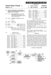
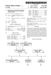
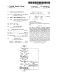
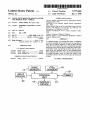
US005775406A
United States Patent [191
[11]
Patent Number:
5,775,406
Ghitea, Jr.
[45]
Date of Patent:
Jul. 7, 1998
[54] VENTILATION MESSAGE DISPLAY SYSTEM
AND METHOD FOR A VEHICLE
_
.
.
Caterpillar. Feb. 1995.
Inventor‘ Nicol“ Ghltea’ Jr" Tlgard' 0mg‘
.
_
.
.
ProDriverTM User Manual, Detroit Diesel Corporation.
.
Man.
Asslgnce' gelghthner corporation‘ Portland“
eg'
CELECT RoadRelayTM User’s Guide, Cummins Cadee.
1993'
6
. '
Primary Examiner—W11liam E. Wayner
[51] Int. Cl. ............................. .. G05D 23/00; F24F 7/06
[52] US. Cl. ......................... .. l65/1l.1: 165/248; 236/94;
454/229
Field of Search
1994.
Model ZOOSAD High Level Pre-Amp OEM Carbon Dioxide
Monitor; v11 Valtronics. Revised Jun. 20. 1996. pp. 1-3;
Revised Jun. 11. 1996. pp. 4-6. & 8.
[21] APPL No‘: 674,134
Jul. 1, 1996
[22] Filed:
[53]
OTHER PUBLICATIONS
Owner’s Manual Caterpillar Driver Information Display,
Attorney, Agent, or Firm—Klarquist Sparlcman Campbell
Leigh & Whinston LLP
[57]
.................................. .. 165/11.1. 249.
165/248; 236/94_ 493; 454/229_ 75_ 257
ABSTRACT
_
_
_
l
_
_
A ventilation d1splay system determines when a vent1lat1on
system has remained in recirculation mode for a prede?ned
_
References Clted
[56]
time. and in response generates a stale air alert message
inside the cab of a truck. The system can generate messages
US Pm DOCUMENTS
3,418.9!4 12/1968 Finkin ..................................... .. 454/75
alerting the driver that the HVAC system has switched into
recirculation mode. and alerting the driver that the recircu~
l?tio" H1096 has IFm?iWd activ? for the Pfcd??lJed time
4,25s,421
5,303.163
When e*qmpped Wlth ‘1 C02 SEIISOL the System can generate
air quality messages based on either the status of the
3/1981 Juhasz et a1.
.. 364/424
4/1994 Ebaugh et a1. ........................ .. 364/550
recirculation mode or the level of CO2 in the cab of the truck
or both.
FOREIGN PATENT DOCUMENTS
40424541
9/1992
Japan ................................... .. 454/229
HvAc
14/ SENSOR
,
'NpluT
_
12 Claims, 2 Drawing Sheets
CO2 /-16
SENSOR
r18
CONTROL
12\ DISPLAY
DEVICE
=
10
4 TIMER
US. Patent
Jul. 7, 1998
Sheet 1 of 2
HVAC
F|G_ 1
002
14/ SENSOR
I
'NPUT
'
\
16
SENSOR/
I
CONTROL
DEVICE
5,775,406
‘
18
Tqh-AER
'
UNIT
12\ DISPLAY
10
DEVICE
FIG. 2 46.1 12 22 2s
HVAC
602
66/ SENSOR
‘
FIG 3
Y
=
SENSOR \68
M74
ND CONVERTERS \70
'
44—\
DISPLAY DEVICE
A
ROM
-J
\
52
¥
(~50
I
k
I
58
EEPROM‘J
‘D
12“
KEYPAD
MEMORY 6Q
72
I
V
l
PORT
“
INTERFACE 54
II
I
3
56f
I
BUZZER /8°
5.775.406
l
2
VENTILATION MESSAGE DISPLAY SYSTEM
AND METHOD FOR A VEHICLE
FIG. 6 is a diagram illustrating an implementation of a
message display to alert the driver that the HVAC system has
been in recirculation mode for a prede?ned time period.
TECHNICAL FIELD
DETAILED DESCRIPTION
The invention relates to a message display system for
vehicles and more speci?cally relates to a message system
for generating messages regarding the air quality in a
vehicle.
BACKGROUND OF THE INVENTION
10
The heating. ventilation. and air conditioning (HVAC)
systems in many of today’s cars and trucks commonly have
The message system can also include a C02 sensor 16 to
a recirculation mode where air is recirculated within the
vehicle. When switched into this mode. the HVAC system
detect when the CO2 level in the vehicle reaches a pre
de?ned level. When equipped with a C02 sensor. the mes
sage system monitors the level of CO2 in the vehicle. and in
recirculates the air in the vehicle rather than drawing “fresh”
air into it. If left on too long. carbon dioxide can build up
addition. keeps track of how long the HVAC system is in the
inside the vehicle and degrade the air quality. As stale air
builds up. the driver can become drowsy due to the lack of
fresh air.
Despite the potential hazard that a build up of CO2 in the
vehicle creates. the inventor knows of no vehicles that have
a message system to warn the driver of this hazard. There is
a need. therefore. for a warning system to alert the driver
when he or she has left the HVAC system in recirculation
mode too long.
recirculation mode. The system can generate a warning
message alerting the driver that the air is stale based either
on the CO2 level in the vehicle. or the length of time that the
HVAC system remains in recirculation mode or both.
The control unit in FIG. 1 monitors the state of the
recirculation mode through the HVAC sensor 16. The HVAC
25
SUMMARY OF THE INVENTION
The invention provides a message display system and
related methods for displaying stale air alert messages in
response to detecting poor air quality conditions in a vehicle.
sensor is a control circuit used to monitor the switch activity
of a recirculation mode control in the HVAC system. For
example in one implementation. it is a control circuit
coupled to a recirculation switch in the HVAC system. and
it generates a signal indicating that the HVAC system is in
30
recirculation mode. The control unit monitors the state of the
recirculation mode by monitoring the signal from the HVAC
sensor and keeps track of elapsed time when the recircula
The message display system monitors the control circuitry
of the ventilation system to determine when it has switched
to recirculation mode. The system tracks the elapsed time
while the ventilation system is in recirculation mode and
generates a warning message if the ventilation system
FIG. 1 is a functional block diagram illustrating one
implementation of a ventilation message system in a vehicle.
In this implementation. a control unit 10 monitors the HVAC
system through an HVAC sensor 14 and generates the
display of a warning message or messages on a display
device 12 when it detects that the HVAC system has
remained in recirculation mode for a predetermined time.
tion mode is active.
The message system can optionally include a timer 18 to
35
keep track of elapsed time when the HVAC is in recircula
tion mode. The timer is not necessary. of course. if the
control unit is implemented using a processor that provides
timer services.
The CO2 sensor shown in FIG. 1 detemtines the CO2 level
in the vehicle and generates a signal representing the CO2
level or representing that the CO2 level has exceeded a
threshold. In the ?rst case. the control unit computes when
the CO2 level has exceeded a prede?ned threshold. while in
the second case. the control unit detects that the CO2 has
exceeded a threshold from the signal generated by the
remains in recirculation mode for a predetermined time.
The system can optionally include a C02 sensor to
monitor CO2 levels in the vehicle. When equipped with the
CO2 sensor. the system can generate air quality messages
when either: 1) the system determines that the CO2 level
exceeds a prede?ned threshold. or 2) the system determines
that the recirculation mode has remained active for a pre
de?ned time period. The system can monitor both conditions
and display an alert message. so long as either of the 45
sensor.
conditions are satis?ed Alternatively. the system can moni
The message system can optionally include an input
tor the recirculation mode as a supplement to monitoring
device 20 to enable the user to enter input commands to the
CO2 level in the vehicle when it detects that the CO2 sensor
control unit and control its display. Preferably located at the
is not operating properly.
dash
of the truck. the input device 20 enables the driver to
50
Further features and advantages of the invention will
supply inputs to the control unit and control the display. For
become apparent with reference to the following detailed
description and accompanying drawings.
example. the driver can use the input device to clear the
'
message display. or the driver or other operator can use the
input device to con?gure the control unit to control how it
BRIEF DESCRIPTION OF THE DRAWINGS
FIG. 1 is a functional block diagram illustrating one
implementation of a ventilation message display system.
FIG. 2 is a perspective view illustrating the layout of
instruments and controls on a dash incorporating one
embodiment of the invention.
55
displays messages.
While the control unit can be located in a variety of places
in the truck. it is preferably located in the dash. The display
and input devices coupled to the control unit are also
preferably located at the dash so that the driver may easily
view the display and access the input device.
FIG. 2 is a diagram illustrating the position of one form
of a display 12 and an input device 20 among the instru
FIG. 3 is a block diagram illustrating the instrumentation
control unit (ICU) in an embodiment of the invention.
FIG. 4 is a diag'am of one implementation of an input
device of the ICU shown in FIG. 2.
FIG. 5 is a diagram illustrating an implementation of a
ventilation message system for a truck. The dash 22 shown
in FIG. 2 includes a number of gauges. including for
message display indicating that the HVAC system has been
placed in recirculation mode.
fuel gauge 28. etc. Instruments located at the dash may
ments and controls on a dash 22 in one implementation of
example. an analog speedometer 24 and tachometer 26. a
5.775.406
3
4
include a parking brake switch 30. air suspension switch 32.
HVAC controls 34-40. etc.
The HVAC controls include a recirculation mode switch
interface 54. The port interface. in this implementation. is an
interface to a data link comprised of a twisted pair cable.
This particular data link is designed according to SAE
34. fan speed control 36. HVAC master switch 38. and air
temperature control 40. The recirculation mode switch 34
microcomputer systems in heavy duty vehicle applications.
J 1708. a standard for serial data communication between
enables a user to select a recirculation mode in which air is
Electronic devices connected on the data link. such as the
recirculated in the vehicle. by a fan (not shown) and a fresh
air mode in which fresh air is drawn from outside the
vehicle. The fan speed control is a conventional control used
to control the fans in the HVAC system. The HVAC master
ICU 48. communicate with each other according to proto
cols de?ned in SAE J 1708 and SAE J 1587. The SAE 11587
switch is a conventional control enabling one to select an
Vehicle Applications.” This standard de?nes the format of
data and messages communicated among microprocessors
connected to a shared data link. and is speci?cally adapted
standard is entitled “Joint SAFJTMC Electronic Data Inter
change Between Microcomputer Systems and Heavy Duty
operating mode for the HVAC system including air
conditioning. defrost. vent. etc.
The dash also includes the display 12 for a control unit of
a message system. The control unit is referred to as the
for use with SAE 11708.
instrumentation control unit (ICU) in this implementation.
A user can con?gure the ICU 48 by setting parameters in
a con?guration ?le and downloading the ?le to the ICU via
the port interface 54. The con?guration ?le includes a
number of parameters that control the operation of the ICU.
One type of parameter is a display format parameter used to
control the message display. By setting the value of a display
The user interface of the instrumentation control unit
includes a message display panel 46 and keypad 44. both
located on the dash. The keypad 44 is one way to implement
the input device 20 shown in FIG. 1. A variety of conven
tional input devices can be used in the alternative.
20
The display device 12 presents a two-line display at panel
parameter to prede?ned values. the user can select among
46. sometimes referred to as the “message center.” In the
prede?ned display formats such as display message once for
7 seconds. or repeat this message every 254 seconds. The
con?guration ?le includes additional parameters used to set
the conditions that trigger a warning message. For example.
implementation shown here. the display panel 46 comprises
a two by 20 vacuum ?uorescent (VF) display. The display
device can be implemented using other conventional display
technology such as a liquid crystal display (LCD). light
emitting diode (LED) or other display device. The illustrated
the activating time for a “stale air” warning message can be
set by setting a value in the con?guration ?le equal to the
activating time. in minutes. for example. or it may be ?xed
input device 20 in the user interface is a keypad including
both dedicated and general purpose function keys. Alterna
at predetermined time. such as 20 minutes.
The ICU 48 also includes an input device such as the dash
tive implementations using conventional input device tech
nology are also possible.
mounted keypad 44 and a display device 12. A speci?c of the
keypad is shown in greater detail in FIG. 4.
The display device 12in FIG. 3 corresponds to the display
An instrumentation control unit (ICU) in the vehicle
controls the display of messages on the display screen of the
display panel 46 shown in FIG. 2. It is responsible for
monitoring operating conditions in the truck including the
35
status of the recirculation mode of the HVAC system.
FIG. 3 is a block diagram illustrating the ICU 48 in one
device 46 described above in connection with FIG. 2. It
should be noted that for a lower cost implementation. an
indicator light with a message indicating that the air in the
cabin is stale could also be used. This indicator light would
be illuminated in the event that the ICU detected stale air
conditions in the cabin.
implementation of the invention. The ICU is typically posi
tioned in the truck cab for easy access. and preferably at the
dash of the truck.
The instrumentation control unit 48 includes a CPU 50.
memory 52 and a port interface 54 for connecting the unit to
a shared communication link 56.
The ICU 48 (FIG. 3) is connected to an HVAC sensor 66
through analog to digital converter (AID) 70. In this imple
mentation the HVAC sensor 66 is a switch that electrically
connects an input of the AID converter with a power supply.
The memory 52 includes programmable ROM 45 When a user selects the recirculation mode via the recircu
(EEPROM) 58. permanent ROM 60 and volatile RAM 59.
The routines for controlling the ICU are stored in ROM 60.
while con?gurable data such as a con?guration ?le is stored
in the EEPROM 58. The memory 52 also includes a form of
temporary memory such as RAM 59 for temporary storage
of program instructions and data.
In one speci?c implementation. the ICU has two CPUs
and its memory includes EEPROM. ROM. and RAM. The
CPUs are 68HC11 microprocessors from Motorola Corpo
ration. A ?rst CPU controls the operation of the message
display system. while a second CPU controls instrumenta
tion integrated with the ICU. Since the second CPU is not
used for the message display system. it is not necessary to
lation switch 34 (shown in FIG. 2). the HVAC sensor 66
55
As shown in FIG. 3. the ICU 48 can be coupled to a C02
sensor 68 to monitor the CO2 level in the cab of the truck.
implement the invention. This speci?c ICU has 8 KB of
external EEPROM. 128K of ROM and 2K of RAM. The
CPUs internal memory comprises 256 Bytes of RAM and
512 bytes of EEPROM. This is only one speci?c implemen
tation of the ICU. A variety of conventional processors and
memory systems can be used to implement the functionality
of the instrumentation control unit.
The ICU 48 can communicate with other electronic
devices connected to a shared data link 56 through the port
(FIG. 3) supplies a signal to the input of the AID converter
70 indicating that the recirculation mode is active. The ICU
is programmed to respond to this signal to display a message
acknowledging that the HVAC system is in recirculation
mode and to generate a warning message when left in this
mode too long. In this implementation. the ICU polls the
input to check whether the HVAC signal is active. In the
alternative. the ICU can be programmed to respond to
interrupts raised when the HVAC signal is activated and
deactivated.
65
The CO2 sensor operates in response to control signals 72
from the CPU 50 in the ICU 48 and provides output signals
74 from which the level of CO2 can be derived. A CO2
sensor suitable for this application is Model 2005AD High
Level Pre-Amp OEM Carbon dioxide Monitor from Val
tronics of Valley Springs. Calif. This CD; sensor passes an
infrared beam through a gas cell to determine the CO2
concentration in the cell. The CPU provides a logic level
high signal to the sensor for a predetermined period (about
5 .775.406
5
6
4. Trip (Miles. hours) (96)
5. Leg (Miles. hours) (98)
500 ms) to turn on an infrared beam. and then provides a
logic low signal for the predetermined time to turn off the
infrared beam. The output signal is an analog waveform
oscillating between a high peak (after the infrared light is on
for the predetermined time) to a low peak( after the infrared
beam is off for the predetermined time). The difference
between the high and low voltages is indicative of the CO2
The dedicated keys are used to request speci?c informa
tion such as the current local time (time). the current
temperature (temperature). fuel used. average miles per
gallon. etc. The trip and leg keys are used to display the
miles travelled and elapsed hours for a trip or a leg of a trip.
level in the gas cell. where the greatest difference means
approximately zero percent CO2 and the smallest difference
The keypad also includes the following general purpose
means the full scale percent CO2 in the cell.
The CPU 50 samples the waveform through the A/D
keys:
converters 70 at a ?rst interval when the waveform is at or
1.
2.
3.
4.
near its high peak and a second interval when the waveform
is at or near its low peak and averages the samples to
eliminated noise. The difference between the average at the
high and low peaks is a measure of how much C02 is in the
gas cell. which is located in the cabin. The CO2 sensor
should be calibrated for temperature. This sensor provides a
temperature signal from which the CPU computes a tem
perature compensation factor (e.g. 0.2% per degree C for
every degree change from zero calibration). The CPU cali
20
The CPU compares the CO2 level computed using the
These keys can be used to scroll through message screens
on the display. enter data. clear messages. etc. For example.
these keys can be used to enter con?guration data such as a
parameter representing the activating time for a stale air
time the HVAC can remain in recirculation mode before the
message system alerts the driver. When a warning message
is displayed. a key or keys may be used to clear a warning
25
message from the display.
In one implementation of the message system. the ICU
displays a message when the HVAC systems enters recir
culation mode. and displays an alert if the HVAC system
remains in recirculation mode for a predetermined time.
FIGS. 5 and 6 illustrate examples of these messages.
warning message. If the CO2 level exceeds the predeter
mined threshold. it generates a warning message.
The ICU 48 shown in FIG. 3 may also include a buzzer
80 as an auxiliary warning device used to produce an audio
alarm to supplement an alert on the display. For example. the
buzzer provides an audio alert for warning conditions such
as “stale air. stop recirculation.” In this implementation. the
buzzer is integrated into the ICU 48. However. a buzzer or
other audio warning device can be implemented as a discrete
Right Arrow Key (104)
Set/Reset Key (106)
warning message. The activating time refers to the length of
brates the sensor by providing a control signal that adjusts
the sensor through control signal path 72.
method above with a predetermined threshold value stored
in the ICU to determine whether it should generate a
Left Arrow Key (100)
Down Arrow Key (102)
FIG. 5 is a diagram illustrating an example display
message 200 to acknowledge that the system has entered
35
device to the ICU as well.
recirculation mode. When the ICU receives a signal from the
HVAC sensor indicating that the user selected recirculation
mode. it enters a display routine to display this message. The
message warns the driver that the air will become stale in a
speci?ed period of time. such as 20 minutes. for example.
In this implementation. the CPU 50 can control the output
of the buzzer to produce different types of audio alarms
based on the nature of the warning. For example. the ICU
The ICU displays this message and then returns to the
normal operation screen 202. In this particular
implementation. the normal operation screen 202 refers
generally to the screen that the ICU was displaying when the
shown in FIG. 3 distinguishes higher priority messages from
other messages by playing a continuous tone or a continuous
ICU replaced it with the alert message. The speci?c infor
mation and format of the information displayed varies
series of pulses. For lower priority messages. the ICU plays
a limited number of pulsed tones. The CPU in the ICU issues
depending on the operating state of the vehicle and. more
control signals to the buzzer to cause it to play a continuous 45 speci?cally. the inputs to the ICU. When the vehicle is in
tone. a continuous series of pulsed tones (a continuous series
motion during normal operating conditions. the ICU dis
of “beeps”). or a pulsed response (e.g.. a limited number of
plays fuel economy data and an odometer reading. During
“beeps”). The ICU can be con?gured to play these audio
the ignition sequence. the ICU displays diagnostic
warnings along with display messages by setting corre
information. and when the vehicle is stationary. the user can
sponding parameters in its con?guration ?le. The value of
scroll through set-up screens and diagnostic information.
While the ICU displays these types of display screens in this
implementation. other alternative message screens may be
the parameter can specify that an audio warning is to be
played along with visual message and can also specify the
type of audio alarm (e.g.. continuous tone. continuous series
of pulses. or limited number of pulsed tones).
The particular ICU used in this implementation is manu
factured by Joseph Pollak of Boston. Mass. for Freightliner
Corporation. The instrumentation control unit is available as
displayed.
55
a replacement part from Freightliner Corporation.
FIG. 4 is a diagram of one implementation of the keypad
used with the ICU. The keypad includes a number of keys
to enable the driver to query the ICU for information and to
control its operation. The keypad shown in FIG. 4 includes
the following dedicated keys:
1. Time (90)
2. Temperature (92)
3. Fuel (Fuel used. Avg. MPG) (94)
The ICU can display a message in a variety of di?erent
formats. In this implementation for example. the ICU can be
con?gured to display a message in any of number of selected
formats such as display message one time only for x
seconds. display message for x seconds and repeat every y
seconds (where x is an integer in a prede?ned range). display
the message until any key is pressed. etc.
The ICU displays messages based on selected formats.
which can be selected by setting display parameters in its
con?guration ?le. Each display message can have an asso
ciated display parameter or parameters that the ICU uses to
65
control the display of the message. The value of the param
eter indicates how the message will be displayed. A value of
NULL or zero means that the message is disabled. a value
5 ,775.406
7
8
of 1 means that the message is displayed once for 7 seconds.
and a value of 2 means the message is displayed 7 seconds
every 254 seconds. If the display parameter has been set to
make an accurate reading. or if the output signals are out of
range. the ICU can then monitor only the HVAC sensor as
any number in the range from 3-253. the message is
displayed until a user presses any key on the keypad. After
the user presses the key. the message is repeated in the
The ICU can use other approaches as well. For example.
the ICU can be programmed to display a warning message
based on whichever condition (CO2 level exceeded. or
activating time in recirculation mode elapsed) occurs ?rst. In
this case. the ICU monitors the CO2 sensor and HVAC
long as the CO2 sensor is not functioning properly.
programmed time (3-253 seconds). and the cycle continues
until the condition that caused the message is no longer
satis?ed. If the display parameter has been set to 254
sensors through their respective input signals. The ICU
displays an alert message when it detects either of the
conditions: 1) the CO2 level exceeds a threshold or 2) the
HVAC system has remained in recirculation mode for the
(always on). then the warning message is displayed as long
as the ICU detects the condition that initially caused the
display of the warning message.
activating time. The ICU may continue to display a warning
When the HVAC system enters the recirculation mode.
the ICU enters a display routine to track the elapsed time
while in recirculation mode. This routine controls the dis
play of warning message if the elapsed reaches a prede?ned
time called the “activating time.” The activating time. in this
example. corresponds to the time specified in the message
200 shown in FIG. 5 (20 minutes. for example).
As the ICU accumulates the elapsed time. it also contin
message as long as either of these conditions remain active.
As an additional warning. the ICU can sound an audio
alarm using an audio warning device such as the buzzer
shown in FIG. 3 to alert the driver that it is displaying a
message. To enable this feature in the ICU. a control
20
the conditions for the message are satis?ed. the ICU sounds
an audio warning in addition to displaying the message on
ues to monitor the state of the recirculation mode. If the
recirculation mode is no longer active. as indicated by the
the display device.
signal (or lack of signal) from the HVAC sensor. the ICU
exits the routine and thus. ceases to accumulate elapsed
time.
If the elapsed time reaches the activating time for the stale
air alert. the ICU displays a warning message such as shown
parameter is set in the ICU’s con?guration ?le. When this
control parameter is set for a particular display message and
The CPU in the ICU can control the audio output of the
25
buzzer to produce di?erent types of audio warnings for
ditferent messages. For high priority warning messages such
as the stale air warning. for example. the CPU instructs the
buzzer to play a more prominent audio warning such as a
continuous series of pulses or a continuous pulse tone. For
at 210 (FIG. 6) alerting the driver that the air may be getting
stale.
FIG. 6 illustrates an example of a warning message 210
displayed when recirculation mode remains active for a
prede?ned time. As shown. the message alerts the driver to
turn off the recirculation mode. The ICU returns to the
normal operation screen according to the selected display
mode set for the message as described above. If the message 35
is set to repeat or display the warning message persistently.
the ICU continues to monitor the status of the recirculation
mode and repeats the warning message or displays it per
sistently or continuously as long as the HVAC system
remains in recirculation mode.
lower priority messages such as when the HVAC system
enters recirculation mode. the ICU plays a less prominent
audio warning such as a limited number of pulsed tones.
This feature enables the ICU to distinguish among diiferent
warning messages based on their importance.
Having described and illustrated the principles of our
invention with reference to a preferred embodiment and
several variations thereon. it should be apparent that the
invention can be modi?ed in arrangement and detail without
departing from its principles. Accordingly. we claim all
modi?cations as may come within the scope and spirit of the
following claims.
When the ICU detects that the recirculation mode is no
We claim:
longer active. it exits the display routine and ceases to repeat
1. In a vehicle having a ventilation system with a recir
the warning message. The ICU returns the display to the
culation
mode. a message system for the vehicle comprising:
normal operation screen 212.
a display device;
The ICU can also trigger warning messages based on 45
an HVAC sensor operable to generate a signal indicating
inputs from a C02 sensor. The warning message 210 in FIG.
whether the ventilation system is in the recirculation
6 is an example of possible format for a message alert
mode;
generated in response to an input signal from the CO2 sensor
a control unit coupled to the HVAC sensor and the display
indicating that the CO2 level in the cab has exceeded a
device. the control unit being operable to receive the
50
threshold value.
signal from the HVAC sensor. being operable to detect
When the ICU is equipped with the CO2 sensor. the ICU
when the recirculation mode is active by monitoring the
signal. and being operable to detect a ?rst condition in
which a prede?ned time period has elapsed while the
can use the HVAC sensor as a supplement to evaluating air
quality in the cab of the truck through the CO2 sensor (FIG.
I and FIG. 3). For instance. the ICU can display a warning
message such as the one in FIG. 6 in both of the following
2 cases: 1) when the C02 level exceeds a threshold. as
55
HVAC system has been in the recirculation mode. and
in response to detecting that the ?rst condition is
detected through the CO2 sensor. and 2) when the ICU
satis?ed. being operable to generate the display of an
determines that the HVAC has been in recirculation mode
for a predetermined period of time.
alert message on the display device.
2. The system of claim 1 wherein the control unit is
coupled to an audio warning device; and wherein the control
unit is operable to instruct the audio warning device to play
an alarm in response to detecting that the ?rst condition is
satis?ed.
3. The system of claim 1 wherein the control unit is
operable to display a message indicating that the recircula
tion mode is active in response to detecting that the HVAC
system has been switched into recirculation mode.
Alternatively. the ICU sensor can use the HVAC sensor as
a back up to the CO2 sensor in cases where it determines that
the CO2 sensor is malfunctioning. In this alternative
approach. the ICU only monitors the HVAC sensor if it
determines that the CO2 is not functioning properly. For
instance. the ICU can monitor the output signals from the
CO2 sensor to perform diagnostic error checking. If the ICU
detects that the temperature is too high or out of range to
65
5.775.406
9
4. The system of claim 3 wherein the control unit is
coupled to an audio warning device; and wherein the control
unit is operable to instruct the audio Warning device to play
a ?rst alarm in response to detecting that the HVAC system
has been switched into recirculation mode. and is operable
to play a second alarm. di?'erent from the ?rst alarm. in
response to detecting that the ?rst condition is satis?ed.
S. The system of claim 1 further including a C02 sensor
10
mode. being operable to keep track of elapsed time
5
8. In a cab of a truck having a ventilation system that
recirculates air in the cab in a recirculation mode. a method
coupled to the control unit. the CO2 sensor being operable
to detect whether the level of CO2 in the vehicle has to
exceeded a threshold. and in response to detecting that the
level of CO2 in the vehicle has exceeded the threshold. the
CO2 sensor being operable to generate an input signal to the
control unit;
wherein the control unit is operable to receive the input
signal and is operable to generate the display of an alert
message in response to receiving the input signal from
the CO2 sensor.
6. The system of claim 1 wherein the control unit is
operable to monitor the signal from the HVAC sensor after
15
20
the prede?ned time period has elapsed. and is operable to
repeat or persistently display the alert message as long as the
HVAC system remains in recirculation mode.
7. In a truck with a cab and an HVAC system with a
recirculation mode to recirculate air through the cab. a
25
message display system comprising:
a C02 sensor operable to sense CO2 level inside the cab
and operable to generate a ?rst signal indicating that the
CO2 level has reached a prede?ned threshold;
a HVAC sensor operable to generate a second signal
30
tion mode;
detecting when the ventilation system is placed in recir
culation mode;
tracking the elapsed time that the ventilation system is in
the recirculation mode; and
when the elapsed time reaches or exceeds an activating
time. displaying a stale air alert message in the cab of
the truck.
9. The method of claim 8 further including:
displaying a message acknowledging that the recircula
tion mode is active in response to detecting that the
ventilation system has been placed in the recirculation
mode.
10. The method of claim 8 further including:
predetermined time period and then replacing the stale
alert message with a normal operation message;
35
tinuing to monitor the ventilation system control cir
cuit; and
repetitively displaying the stale air alert message at pre
determined intervals as long as the ventilation system
remains in the recirculation mode.
11. The method of claim 8 further including:
monitoring CO2 level in the cab of the truck; and
when the CO2 level reaches a prede?ned limit. displaying
an alert message.
and
the instrumentation control unit also being in communi
signal. the instrumentation control unit being operable
monitoring a ventilation system control circuit to detect
when the ventilation system is placed in the recircula
after the elapsed time reaches the activating time. con
ing message in response to receiving the ?rst signal;
cation with the HVAC sensor to receive the second
for monitoring air quality and generating air quality
messages. the method comprising:
when the elapsed time reaches or exceeds an activating
time. displaying the stale air alert message for a ?rst
indicating Whether the HVAC system is in the recircu
lation mode;
an instrumentation control unit including a display device
and an input device;
the instrumentation control unit being in communication
with the CO2 sensor to receive the ?rst signal. the
instrumentation control unit being operable to monitor
the ?rst signal from the CO2 sensor to detect whether
the CO2 level in the cab has exceeded the prede?ned
threshold. and being operable to generate a ?rst warn
when the recirculation mode is active. and being oper
able to generate a second warning message when the
HVAC system has remained in recirculation mode for
a prede?ned time.
45
12. The method of claim 10 further including:
monitoring a C02 level sensor;
in response to detecting that the CO2 level sensor is
malfunctioning. executing each of the steps in claim 8.
to monitor the second signal from the HVAC sensor to
detect Whether the HVAC system is in recirculation
*****