1
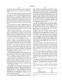
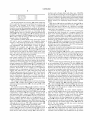
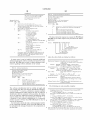
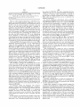
USOO589008OA
Ulllted States Patent [19]
[11] Patent Number:
Coverdill et al.
[45]
[54]
Date of Patent:
5,890,080
Mar. 30, 1999
TRUCK WITH MONITOREI) AND
5,365,436
11/1994 Schaller et al.
RESETTABLE ELECTRONIC CONTROL
5,693,876
12/1997 Ghitea, Jr. et al. ..................... .. 73/114
UNITS
. 364/424.03
OTHER PUBLICATIONS
[75] Inventors? Cary N- COVEFdHL Boring, Oregé
Owner’s Manual Caterpillar Driver Information Display,
Steven A. Wright, Charlotte, NC.
_
_
_
Caterpillar, Feb 1995'
_
ProDriverTM User Manual, Detroit Diesel Corporation, Mar.
[73] Ass1gnee: Frelghtllner Corporation, Portland,
1994'
0mg‘
CELECT RoadRelayTM User’s Guide, Curnrnins Cadec
copyright 1993.
Appl. No.: 673,697
_
_
Primary Examiner—Michael Zanelli
Flled'
Jun‘ 25’ 1996
Attorney, Agent, or Firm—Klarquist Sparkrnan Campbell
Int. Cl? ......................... .. G06F 19/00; G01M 17/00
Leigh & Whinsteh LLP
US. Cl. ................................ .. 701/29; 701/33; 701/32
Field of Search ................................ .. 701/29, 31, 32,
[57]
701/36, 50, 33; 340/459, 461, 462
A method for determining installed electronic devices on a
truck and for providing a centraliZed reset to clear faults in
the installed electronics. An instrurnentation control unit in
the cab of a truck deterrnines installed electronics by
requesting electronics on a shared data link to transmit data
References Cited
US‘ PATENT DOCUMENTS
4,258,421
4,533,962
3/1981 JuhasZ et al. ......................... .. 364/424
8/1985 Decker et a1,
______ __ 360/5
4,825,362 4/1989 Minami et al. ..
4,835,671 5/1989 Sate et al
4J843J557 6/1989 Ina ct a1~ ~~
4’972’184 11/1990 GO et a1‘
5,173,856 12/1992 Purnell et a1.
5,250,761
10/1993
Koyanagi ...... ..
ABSTRACT
Oh the data link- The Control unit identi?es the installed
devices from the transmitted data. Data describing the
364/200
installed devices including rnanufacturer, model, and
364/186
installed softWare can be obtained and displayed for diag
364/431-11
nostic purposes. The instrurnentation control unit provides a
34O/825'25
364/42404
centraliZed reset for resetting the electronic devices on the
data link
177/141
5,303,163
4/1994 Ebaugh et al.
5,345,384
9/1994 Przybyla et a1. ................. .. 364/424.04
'
...... .. 364/550
15 Claims, 9 Drawing Sheets
______________________ __i____________________________________________________
34
36
38
4O
42 44 46 48
444
4444
AIR CONDITIONING
PROTECTION
UNIT
5O 52 54 56
4444
POWERTRAIN
r22
CONTROL
UNIT
58 6O 62 64
ANTILOCK 26
I24
BRAKE
UNIT
.J
r
I
|
4444
|
AIR SUSPENSION
I
=
CONTROL
UNIT
I
:
I
28
|
I
I
I |
J
/
J I
20
COLLISION
I
:
COMMUN-
SECURITY
WARNING
ICATION
ALARM
|
UNIT
UNIT
/
UNIT
\
:
I
82
1
DATA
LOGGING “'30
UNIT
74 76
\
INSTRUMENTATION
78
CONTROL
UNIT
80
132
I DATA
84
PORT
I
I
66 68 70 72
I
I
l
U.S. Patent
Mar. 30, 1999
r DOOR
94 SENSORS
Sheet 2 0f 9
HVAC
SENSORS
PARKING
q
BRAKE SENSORS 98
\
COOLANT
96
FIG 2
5,890,080
LEVEL D
SENSOR 100
A/D
W'PER
-
-
/coNvEI=ITEPS
SENSOR E2
106
TURN
SIGNALS _\
104
110w
TO DATA
FLUID
90W
9
P LOGGING UNIT‘
DISPLAY
KEYPAD
DEVICE
“92
M
MEMORY
ROM
J
F
-\
88
‘
II
II
II
“
RAM
'\
87
EEPROM \
t
‘
CPU
‘
PORT
-\
'NTEQFACE 84
as
——"—;——I
20
‘
108
/
BUZZER
U.S. Patent
Mar. 30, 1999
Sheet 3 0f 9
5,890,080
U.S. Patent
Mar. 30, 1999
5,890,080
Sheet 6 0f 9
FIG. 7 @
BUILD MESSAGE
INCLUDING PID O,
PID 194 AND
POSSIBLY PID 234
AND PID 243
f2")
I
BROADCAST
MESSAGE
/212
I
LISTEN FOR
RESPONSE
/214
I
RECORD
RESPONSE
218
NO
YES
COMPARE RESPONSE
WITH EXPECTED LIST
f 220
r222
DISPLAY RESULTS
(E. G., MISSING OR UNKNOWN COMPONENTS)
RETURN
U.S. Patent
Mar. 30, 1999
Sheet 7 0f 9
5,890,080
.W
Eis?1 :
£x24598E62m8
32coo9_0m5.cwm>
DTE:Oi_?Oc@E6omzQ5T82?aoE0i>4:D_
¢235.6m| IHUM m?nw..Ewm65sb3_w6.E
<w.GE
@
[email protected]:;wo3
@
35:00m
2m9%2%:5 N
N,»
L
2 ml
i.nHam?UgNwzu
U.S. Patent
Mar. 30, 1999
Sheet 8 0f 9
5,890,080
o
c92o5m8>
x£H950.2E86m
..
.
'
,
.
¢
~
.
.
..
.
..
~
..
.
,
.
.
.
-.
.
.
.
‘
.
.
2
.
E_TnQ.HE_ “0iTSEQG6£[email protected]:
..
.
...
I
v
.
..
.
030m2:05?@20 m
22Ewcom=9 E
$EQ62G0E $Ew620E
22w-
mvm1|
.E?éb.wWM
5,890,080
1
2
Another problem associated With electronic devices
TRUCK WITH MONITORED AND
RESETTABLE ELECTRONIC CONTROL
UNITS
installed on trucks is that they can exhibit erroneous behav
ior if not properly reset before delivery to the customer.
During the truck assembly process, an electronic control unit
TECHNICAL FIELD
may be used in a manner that makes it think there is a
problem or a “fault.” For instance, it is common for an
The invention relates to a truck including systems for
assembler to poWer up an electronic subsystem before
installing it in a vehicle. In these circumstances, the sub
system usually generates a number of faults because all of its
monitoring and resetting electronic control units mounted in
the truck.
BACKGROUND OF THE INVENTION
10
sensors are not yet installed and calibrated.
Electronic controls are Widely used in trucks for a variety
The faults generated during the assembly process can be
of applications. For example, sophisticated electronic con
trol devices including programmed microprocessors are
commonly used to control antilock brake systems,
poWertrains, and transmissions. These electronic devices
a serious problem for customers and service technicians
because they make it appear as if there are problems With the
vehicle. It is imperative, therefore, that all of the faults be
15
cleared from the trucks electronics at the truck manufac
have provided neW functionality, such as the antilock brake
turing plant. This is often time consuming because it may
systems, and have improved performance of existing com
ponents. While electronics have signi?cantly improved
functionality and performance, they have also increased the
complexity of trucks.
involve entering a series of commands at a keypad just to
20
electronic subsystems in the truck. Often the diagnostic tool
or computer require considerable recon?guration to take
advantage of proprietary softWare from the vendor of the
As the use of electronic systems in trucks has groWn, a
number of electronic control devices or units have been
developed for speci?c applications. For example, engine
manufacturers have designed special purpose computers for
controlling and monitoring engine performance. Brake
manufacturers have designed electronic control devices to
control sophisticated antilock brake system. Still other
manufacturers have developed control units for air suspen
sion systems. Since each of these devices are designed for
different purposes, they are not typically designed to Work
together or to communicate With each other.
With the increasing sophistication of truck electronics, a
electronic subsystem.
25
SUMMARY OF THE INVENTION
In one aspect, the invention provides a method and
apparatus for determining installed electronics on a truck. In
30
de?nes the requirements of the hardWare and basic protocol
for communicating data betWeen electronic control systems
In one speci?c embodiment of the invention, a truck is
interconnected via a truck data link. The ECUs are instructed
35
40
or units. SAE 11587 provides a common format for mes
sages and data communicated betWeen the electronic control
systems.
Despite the adoption of these standards by many in the
industry, they alone do not solve many problems associated
With installing and servicing electronic devices on today’s
trucks. For example, the standards do not provide any
mechanism for determining Which components are installed,
45
about the installed components. For example in one method
control unit broadcasts a request for data transmission on the
data link, and then monitors the responses from the installed
components. The instrumentation control unit identi?es the
installed components from their responses and stores a list of
the installed components. This list can be doWnloaded to an
One problem associated With these electronic systems is
ensuring that they function properly and that they are
external computer using diagnostic softWare and can be
displayed for use in analyZing the compatibility of the
installed components.
55
after-market electronic parts Which do not operate properly
or are incompatible With other components. In these
60
The lack of proper installation of electronic controls is a
major problem for truck manufactures and service providers.
The instrumentation control unit provides a convenient
method for resetting the installed electronic control units on
the vehicle. The user can access and display diagnostic data
called “faults” via an input device coupled to the instrumen
tation control unit in the cab of the vehicle. In response to
a command entered by the user, the instrumentation control
unit instructs the electronic control units to clear their faults.
For example in one embodiment, the user issues a com
mand from an input device coupled to the instrumentation
control unit to clear faults. If the mileage or other vehicle
Studies shoW that in excess of 50% of electronic compo
nents returned are found to operate properly. As such,
considerable time and money is Wasted in addressing prob
the truck includes an ECU called the instrumentation control
unit located in the cab of the truck. The instrumentation
control unit or an external computer coupled to the data link
for determining installed components, the instrumentation
compatible.
circumstances, it is likely that the truck Will have a number
of electronic components that have never been tested by the
truck manufacturer.
to transmit data via the truck data link. By analyZing this
data, a computer coupled to the truck data link can identify
the installed components. Further data about the model,
manufacturer, and installed softWare can also be determined.
In this speci?c embodiment, the system architecture on
can query the ECUs on the data link to determine Which
components are installed and to obtain more speci?c data
or for determining Whether the installed components are
compatible. The truck manufacturer can build and test the
electronics to make sure that they are operational. HoWever,
it is very common for others to modify the truck With
another aspect, the invention provides an improved method
for resetting the truck electronics.
equipped With a number of electronic control units (ECUs)
need arose to provide a means for communicating data from
the disparate electronic control systems on board the
vehicle. TWo standards developed for communication
betWeen electronic devices in vehicles are SAE (Society of
Automotive Engineers) 11708 and 11587. SAE 11708
reset or re-program a single device. In other cases, it may
require a technician to connect a hand held diagnostic tool
or computer to an electronic subsystem to separately reset
65
parameter (e.g. engine hours, etc.) is Within predetermined
lems that could have been avoided had the electronics been
limits, such as beloW a predetermined mileage value, the
installed and con?gured properly.
instrumentation control unit interprets the command as a
5,890,080
4
3
request to clear all faults throughout the vehicle. The faults
may be automatically cleared if the vehicle parameter,
preferably mileage, is below a threshold value. The instru
The communications unit is a device that supports remote
communication With the truck. Typical forms of communi
cation include satellite, cellular, short distance radio
frequency, and infrared. These types of communication
devices are available from Qualcomm of San Diego, Calif.,
HighWay Master of Dallas, Tex., or RockWell Transportation
Electronics of Cedar Rapids, IoWa.
mentation control unit broadcasts a message to the electronic
control units on the data link instructing them to clear their
faults. This feature enables a technician to clear all faults
easily from a central location. No sophisticated diagnostic
tools or special purpose softWare is necessary to reset a
variety of devices on the data link.
Further features and advantages of the invention Will
become apparent With reference to the folloWing detailed
The collision Warning unit is responsible for Warning of
possible collisions. It is available from Eaton-Vorad Tech
10
The system architecture in FIG. 1 also includes a data port
84 for coupling external devices to the on-board data link.
This data port 84 enables an external computer to receive
description and accompanying draWings.
BRIEF DESCRIPTION OF THE DRAWINGS
FIG. 1 is a block diagram illustrating the system archi
and transmit messages on the data link. It also enables an
15 external computer to establish a connection With an ECU on
the netWork to either doWnload data or retrieve data from
memory in an ECU on the data link.
tecture in an embodiment of the invention.
FIG. 2 is a block diagram illustrating the instrumentation
control unit in an embodiment of the invention.
FIG. 3 is a diagram of a keypad used for input to the
instrumentation control unit illustrated in FIG. 2.
The data link 20, in this implementation, is a serial
20
speci?c embodiment is based on the 11708 standard, it is not
25
puter coupled to the on-board data processing system.
FIG. 6 is block diagram illustrating the data logging unit
truck.
FIG. 9 is a diagram illustrating hoW the ICU can be used
30
35
to reset electronics devices on a data link in a truck.
DETAILED DESCRIPTION OF THE
INVENTION
FIG. 1 is a block diagram illustrating the system archi
particular data link is designed according to SAE 11708, a
puter systems in heavy duty vehicle applications. While this
shoWing the keypad and display of the instrumentation
in one embodiment of the invention.
FIG. 7 is a How diagram illustrating an embodiment of a
method for determining installed components on a truck.
FIGS. 8A and 8B are examples of screen displays used to
identify installed electronic components and softWare on a
communication path connecting the ECUs together. This
standard for serial data communication betWeen microcom
FIG. 4 is diagram of the layout of a dash in a truck,
control unit of FIG. 2.
FIG. 5 is a block diagram illustrating an external com
nologies of San Diego, Calif.
critical that the invention be implemented in this speci?c
manner. One possible alternative is to use a data link
constructed according to SAE 11939.
In one speci?c embodiment, the data link 20 is comprised
of a tWisted pair cable operating at 9600 baud. Designed
according to the SAE 11708 standard, the data link forms a
communication channel among electronic control units
coupled to it. Electronic control units generate a digital
signal on the data link by applying a voltage differential
betWeen the tWo Wires in the cable. A voltage differential
above a speci?ed threshold represents a logic high value,
While a voltage differential beloW a speci?ed threshold
represents a logic loW value. This type of data link is
particularly advantageous for hostile environments because
the signal is more robust and impervious to signal degrada
40
tecture in an embodiment of the invention shoWn schemati
cally on a truck 10. Truck 10 may be conventional With a
tion. HoWever, other alternative communication media
could be used in place of the 11708 cable.
The ECUs connected on the netWork communicate With
ture on board the truck includes a number of electronic 45
each other according to protocols de?ned in SAE 11708 and
SAE 11587. The SAE 11587 standard is entitled “1oint
SAE/TMC Electronic Data Interchange BetWeen Micro
control units (ECU) coupled together With a data link 20.
In particular, the system includes an air conditioning
protection unit 22, a poWertrain control unit 24, an antilock
This standard de?nes the format of data and messages
communicated among microprocessors connected to a
cab, an engine, Wheels, a drive train, brakes and other
features commonly found on a truck. The system architec
brake unit 26, an air suspension control unit 28, a data
logging unit 30, and an instrumentation control unit 32. The
computer Systems and Heavy Duty Vehicle Applications.”
shared data link, and is speci?cally adapted for use With
50
SAE 11708.
ECUs on the data link also typically have one or more
According to SAE 11708/11587, the ECUs 22—32, 78—82
sensors and actuators (34—76) used to monitor and control
on the data link 20 communicate by passing messages to
performance of the respective subsystems. These ECUs
represent only one possible system con?guration. The sys
each other. The ECUs can be either receivers, or receivers
tem can optionally include other ECUs including a collision
55 instrumentation control unit 32 is a transmitter and a
Warning unit 78, a communication unit 80, and a security
alarm unit 82.
receiver. It acts as a transmitter When requesting data from
or resetting the ECUs on the data link 20, and acts as a
The ECUs on the data link are available from a variety of
receiver When listening for data transmitted from other
and transmitters. In this particular implementation, the
ECUs.
vendors. The poWertrain control unit is typically provided by
the engine manufacturer. Possible sources include Detroit
60
Diesel Corporation of Detroit, Mich., Caterpillar Inc. of
Mossville, Ill., or Cummins Engine Company of Columbus,
Ind. The antilock brake unit is typically provided by the
by the total message length de?ned in the SAE 11708
brake vendor such as Allied Signal Truck Brake Systems Co.
(Bendix) Elyria, Ohio, or RockWell-Wabco of Troy, Mich.
The air conditioning protection unit is available from Index
Sensors and Controls, Inc. of Redmond, Wash.
A message in this format includes the folloWing: 1) a
module ID (MID), 2) one or more parameters, and 3) a
checksum. The number of parameters in a message is limited
65
standard. The module identi?cation numbers are assigned to
transmitter categories as identi?ed in SAE 11587. The MID
portion of a message speci?es the origin or transmitter of the
message. In the majority of cases, messages are broadcast on
5,890,080
5
6
the data link Without specifying a receiver. However, the
receiver after the MID of the transmitter for special appli
CPUs are 68HC11 microprocessors from Motorola Corpo
ration. A ?rst CPU controls the operation of the message
display system and executes routines to determine installed
cations.
The messages passed among the ECUs convey informa
components and to clear faults of ECUs on the data link and
stored events in the data logging unit. The second CPU
message format can be extended to include the MID of a
controls dash instrumentation integrated With the ICU. The
tion by one or more parameters contained Within them.
second CPU is not critical to the invention but is mentioned
According to the SAE 11587 standard, the ?rst character of
every parameter is a parameter identi?cation character
(PID). The parameter identi?ed by the PID directly follows
the PID. The SAE 11587 supports different data formats
10
including a single character, a double data character or more
than tWo data characters representing the parameter data.
Several parameters can be packed into a message, limited in
this speci?c example by the maximum message siZe as noted
above.
In this implementation, the ECUs 22—32, 78—82 commu
nicate With each other over the data link 20 according to the
SAE standard 11708. The standard describes methods for
accessing the data link and constructing messages for trans
15
fer over it. It also de?nes a method for resource contention 20
among the ECUs on the data link.
25
30
In some cases tWo or more transmitters may attempt to
broadcast a message at one time, giving rise to a collision.
To resolve a con?ict among transmitters, messages have a
priority according to their message identi?ers. The MIDs of
higher priority transmitters have a greater number of bits set
of the ICU. A variety of conventional processors and
memory systems can be used to implement the functionality
of the instrumentation control unit.
The ICU also includes an input device 90 and a display
device 92. In this implementation, the input device 90 is a
ten key keypad. The display device 92 presents a tWo-line
display, sometimes referred to as the “message center.” In
one implementation, the display device comprises a tWo by
20 character vacuum ?uorescent (VF) display. Alternative
implementations are also possible such as a liquid crystal
display (LCD) or other display device.
(94—104) through analog to digital converters 106. For
example, the ICU in this implementation is coupled to: door
transmit its message. The transmitter broadcasts its message
onto the data link. Each of the ECUs that operate as receivers
on the data link Will receive the message. HoWever, receiv
ers only act on a message if programmed to do so.
bytes of EEPROM. This is only one speci?c implementation
The ICU in FIG. 2 is connected to a number of sensors
An ECU Wishing to transmit data on the data link ?rst
Waits for a lull in transmission of data on the data link. In this
particular implementation, the length of the lull is 200
milliseconds. After detecting this lull, the ECU attempts to
here to be complete. This speci?c ICU has 8 KB of external
EEPROM, 128K of ROM and 2K of RAM. The internal
memory of the CPU comprises 256 Bytes of RAM and 512
sensors (94) for detecting When the cab doors are open or
closed; HVAC sensors (96) for determining Whether fresh
air is circulating in the cab; parking brake controls (98) for
sensing Whether the parking brakes are applied; a coolant
level sensor (100) for detecting When the coolant level drops
beloW a speci?ed level; Wiper ?uid sensors (102) for deter
mining When the Wiper ?uid drops beloW a speci?ed level;
and turn signal controls (104) Which indicate When a turn
signal is applied.
The speci?c sensors used in this embodiment are not
35
at a logic level one. When more than one message is
broadcast at a time, the more dominant message takes
critical to the invention. These sensors are illustrated to
demonstrate that ECUs can include a variety of sensors
priority over lesser dominant messages. Since a loWer pri
and/or actuators. During installation or repair, sensors such
as these can generate faults in their respective ECUs. These
types of faults need to be cleared to ensure that the data
ority message is blocked by a higher priority message, the
transmitter of the loWer priority message Waits and retrans
mits the message after another lull. An ECU on the data link
Will continue to attempt to send a message until it is
40
erly.
The ICU can also include a buZZer 108 used to notify the
successfully broadcast to the data link.
While this particular embodiment is implemented accord
ing to the SAE 11708 standard, this is only one example of
the media that can comprise the data link 20. Other alter
natives are possible as Well. For example, the data link 20
can be implemented according to SAE 11939 as Well.
FIG. 2 is a block diagram illustrating the instrumentation
control unit (ICU) in an embodiment of the invention. As
explained in further detail beloW, the ICU can be used to
check electronic components installed on the truck.
Although it may be located anyWhere on the truck, the ICU
is typically positioned in the truck cab for easy access, and
most preferably at the dash of the truck. It can also be used
45
and its memory includes EEPROM, ROM, and RAM. The
open,” “parking brake applied and vehicle in motion,”
is integrated into the ICU. HoWever, a buZZer or other audio
transducer can be implemented as a discrete device to the
ICU.
The particular ICU used in this implementation is manu
factured by Joseph Pollak of Boston, Mass. for Freightliner
Corporation. The instrumentation control unit is presently
55
available as a replacement part from Freightliner Corpora
tion.
FIG. 3 is a diagram of one implementation of the keypad.
The illustrated keypad includes the folloWing dedicated
The instrumentation control unit includes a CPU 80,
memory 82 and a port interface 84 for connecting the unit to
the data link 20. The memory includes programmable ROM
urable data such as a con?guration ?le is stored in the
EEPROM 86. The memory 82 also includes a form of
volatile memory such as RAM 87 for temporary storage of
program instructions and data.
In one speci?c implementation, the ICU has tWo CPUs
driver When certain Warning conditions are detected. Typical
examples of these Warning conditions include “cab door
“coolant level loW,” etc. In this implementation, the buZZer
to reset faults and “events.”
(EEPROM) 86 and permanent ROM 88. The routines for
controlling the ICU are stored in ROM 88, While con?g
management system on board the vehicle is operating prop
keys:
60
1. Time
(114)
2. Temperature
(116)
3. Fuel
4. Trip Miles and Hours
5. Leg Miles and Hours
(118)
(120)
(122)
65
The keypad also includes the folloWing general purpose
keys:
5,890,080
8
7
medium such as ?oppy disks, hard disks, tape, CD-ROM,
1. Left Arrow Key
2. DoWn Arrow Key
(124)
(126)
3. Right ArroW Key
4. Set/Reset Key
(128)
(130)
etc. and other devices that use electrical, magnetic, optical or
other recording material. Main memory 162 stores programs
such as a computer’s operating system and currently running
application programs. Main memory 162 also includes video
display memory for displaying images through a display
The keypad includes an event key 132 Which enables the
driver to specify that an event or problem has occurred With
the vehicle. For example, if the driver is experiencing
problems With the transmission, he or she can depress the
event key to record the transmission problem. In response,
the data logging unit 30 receives an interrupt signal from the
keypad 90 of the ICU and creates an event ?le. In this
implementation, there is a discrete connection 110 from the
keypad 90 to the data logging unit 30. In addition, the ICU
10
device such as a mouse, a pen, or other device for providing
input data to the computer.
15
can send a message to the data logging unit over the data link
20 to notify it that the driver or other user has triggered a
structure is shoWn because various bus structures knoWn in
20
screens to clear faults and events from a central location.
FIG. 4 is a diagram illustrating the layout of the dash in
together, such as in a microprocessor.
(133—136, for example) and indicator lights (137, for
25
in front of the driver as shoWn. The keypad 139 of the ICU
Moreover, the number and arrangement of the elements of
the computer system may be varied from What is shoWn and
described in Ways knoWn in the art.
An external computer 140, such as a PC, communicates
With the data link 20 on board the truck through the data port
is positioned to the right of the display, Within reach of the
driver. This layout illustrates only one possible layout of the
dash and many other variations are possible.
FIG. 5 is a block diagram illustrating an external com
elements of the computer system in a number of Ways, as
desired. CPU 150 may be comprised of a discrete ALU 156,
registers 158 and control unit 160 or may be a single device
in Which one or more of these parts of the CPU are integrated
one embodiment. The dash includes a variety of gauges
example). The display device 138 of the ICU is positioned
It should be understood that FIG. 5 is a block diagram
illustrating the basic elements of a computer system; the
?gure is not intended to illustrate a speci?c architecture for
a computer system 140. For example, no particular bus
the ?eld of computer design may be used to interconnect the
manual event at the keypad 90.
As explained in further detail beloW, the keypad on the
ICU can be used in conjunction With diagnostic display
device.
Input device 146 and the port 148 to the data link 20 are
peripheral devices connected by bus structure 154 to com
puter 142. Input device 146 may be a keyboard, a pointing
30
puter system coupled to the on-board data processing sys
84 (FIG. 1). As noted above, the data link 20 can be
implemented according to the SAE standards 11708/11587.
In this case, the external computer communicates With the
tem. Service technicians or other users can use an external
ECUs on the data link according to the 11587 and 11708
computer coupled to the data link to analyZe the electronics
protocols.
FIG. 6 is block diagram illustrating the data logging unit
and softWare on board the truck. In one implementation, the
external computer is an IBM-compatible PC, equipped With
the WindoWs Operating System from Microsoft Corporation
and ServiceLink diagnostic softWare from Freightliner Cor
poration. ServiceLink is one example of an application
program used to communicate With ECUs (e.g., the data
logging unit and ICU) on a SAE 11587 data link. Other
softWare applications such as 1Tools and 1Pro from Parasoft
35
in one embodiment of the invention. The data logging unit
monitors and records faults and events. It is relevant to the
method for resetting electronic control units on the data link
because, like the other ECUs on the data link, it may need
to be reset, for example, before delivery of the truck. Events
40
triggered in the data logging unit, such as the manually
triggered event from the keypad 90 of the ICU 32 may need
to be cleared. One signi?cant example is When events
pertaining to the data logging unit are inadvertently gener
ated during the assembly process. In this circumstance, it is
45
desirable to clear the events before delivery of the vehicle.
Computing Solutions (Winston-Salem, NC.) also can be
used to communicate With an ECU on a 11587 data link. A
variety of alternative computers and computer architectures
are also possible as evidenced by the general nature of the
computer architecture shoWn in FIG. 5.
The ICU enables a user to clear faults and events in the data
logging unit conveniently from the dash of the truck.
The data logging unit 180 generally includes memory
The computer system 140 includes as its basic elements a
computer 142, a display device 144, an input device 146,
and serial communication link 148 to the data port 84 on the
data link 20.
The external computer 142 generally includes at least one
182, a microcontroller 184, an interface 186 to the data link,
a real time clock 188, and a poWer supply 190. The memory
182 and the real time clock are coupled to the microcon
troller 184 via a bus 192.
In this implementation, the poWer supply includes a
high speed processing unit (CPU) 150 and a memory system
152 that communicate through a bus structure 154. CPU 150
includes an arithmetic logic unit (ALU) 156 for performing
computations, registers 158 for temporary storage of data
control chip that supplies poWer to the microcontroller from
55
and instructions and a control unit 160 for controlling the
operation of computer system 140 in response to instructions
As noted above, the data logging unit is coupled to the
keypad 90 of the ICU (FIG. 2) to receive an interrupt When
from a computer program such as an application or an
operating system. Any of a variety of processors, including
those from Digital Equipment, Sun, IBM, Motorola, NEC,
Intel, Cyrix, AMD, and Nexgen can be used as the CPU 150.
Although shoWn With one CPU 150, computer system 140
may alternatively include multiple processing units.
Memory system 152 generally includes high-speed main
either the vehicle battery or a lithium battery. The lithium
battery serves as a back-up in the event that the voltage
supplied from the battery is insuf?cient or unavailable.
60
a user actuates the event key on the keypad. This connection
is represented by the manual trigger sWitch 194 shoWn in
FIG. 6. The data logging unit can also receive interrupts
from other devices as Well.
The memory 182 of the data includes both RAM 196 and
memory 162 in the form of a medium such as random access 65 ROM 198. This implementation includes 128 KB of ROM,
memory (RAM) and read only memory (ROM) semicon
ductor devices and secondary storage 164 in the form of a
Which stores the application code executed by the micro
controller. This executable code includes the set-up routines
5,890,080
9
10
used to boot the data logging unit and the data logging
routines used to monitor prede?ned events. This implemen
tation also includes 256KB of battery-backed RAM, Which
is used to implement a FIFO buffer for capturing data from
In a typical case, the manufacturing process proceeds as
folloWs. In processing an order for a neW truck, the main
frame computer at the manufacturing plant generates a
detailed truck speci?cation. The creation of the speci?cation
triggers a number of manufacturing processes necessary to
build the truck according to the speci?cation. Before deliv
the data link and to store event ?les.
In this implementation, the data logging unit monitors
voltage supplied by the vehicle battery through an analog to
digital converter 200, Which converts the 12 volt signal from
the battery to a digital signal compatible With the microcon
troller 184.
10
The real time clock 188 is used to track time in the truck.
While recording event data, the data logging unit time
stamps data With the time kept by the real time clock. In this
implementation, the data logging unit is the centraliZed time
keeper for the ECUs on the data link. Thus, it serves as a 15
common time reference for faults and events that occur in
the system.
The data logging unit performs a data monitoring func
tion. Coupled to the data link, the data logging unit listens
for periodic data messages broadcast over the data link. The
data link continuously records a snapshot of data from the
data link into the FIFO buffer. In this implementation, the
data logging unit is programmed to continuously store the
20
most recent 60 seconds of data from the data link. Some
examples of the data monitored by the data logging unit are
30
35
For some types of data, the data logging unit captures a
40
data logging unit. When one of the prede?ned events occurs,
the data logging unit stores the last 60 seconds Worth of data
to memory and begins storing the next 60 seconds Worth of
data. In total, in this example, the amount of data stored for
link, and then examining the response. To implement this
PID 0 — Request Parameter
Used to request parameter data
transmission from other components
on the data link.
Data Type: Unsigned Short Integer
Resolution: Binary
Maximum Range: 0 to 255
Transmission Update Period: As needed
Message Priority: 8
Format: PID
more event ?les from the data logging unit.
0
Data
a
a
Parameter ID of the requested parameter
55 PID 194 — Transmitter System Diagnostic Code and Occurrence Count
Table
Parameter Data Length: Variable
the ICU or external computer to verify that the data logging
unit is installed properly and is compatible With other
Data Type: Binary Bit-Mapped
Resolution: Binary
60
be reset from another device on the datalink. BeloW We
describe hoW the ICU or an external computer can be used
to determine installed components on the data link. We also
describe hoW the ICU can be used to reset the trucks 65
electronics and clear stored events in the data logging unit.
Installation of Electronics
protocols.
Parameter Data Length: 1 Character
an event includes tWo minutes and one second Worth of data.
This data is recorded in an event ?le in memory. An external
computer can be coupled to the data link to extract one or
devices on the data link. The data logging unit can also be
programmed to clear any faults or events it has generated.
This is a useful feature that enables the data logging unit to
transferred betWeen memory of the ICU and an external
computer over the data link using the SAE J1587/J1708
functionality, the ICU uses the folloWing parameters set
forth in SAE 11587:
events can be de?ned by a PID broadcast on the data link,
or by a discrete signal (such as an interrupt) received at the 45
request for data from the ICU or other computer on the data
link such as an external computer. This functionality enables
This list can be updated from time to time and can be
transferred from memory of the ICU to the external com
In one implementation, the ICU determines installed
components on the truck by broadcasting a message request
ing information from each of the components on the data
neW instance or slice of data once every second and stores
The data logging unit is programmed to respond to a
?guration ?le to the ICU including a list of electronic
components and possibly softWare installed in the truck.
puter. In this implementation, con?guration ?les can be
Engine Speed (RPM); PID 190
it in the buffer. When the buffer is full, the most recent
second of data overWrites the oldest snapshot of data.
In addition to continuously storing the data listed above,
the data logging unit also monitors prede?ned events. These
computer polls the components on the truck through the data
port and records the response.
An external computer can be used to doWnload a con
Output Torque; PID 93
Engine Oil Pressure; PID 100
Turbo Boost Pressure; PID 102
Coolant Temperature; PID 110
the truck are sometimes modi?ed, making them incompat
ible. As a result, the electronic devices listed in the con?gu
ration ?le may not be consistent With the electronic devices
actually installed on the vehicle. To diagnose these compat
ibility problems, it is necessary to determine Whether the
electronics have been modi?ed and to determine Which
version of hardWare and softWare is stored on the vehicle.
In this implementation, the installed components can be
determined from: 1) the ICU or other ECU on the data link;
or 2) an external computer (FIG. 5) coupled to the data link
20 via the data port 84. In the ?rst case, the ICU (or other
on-board ECU) polls the components on the truck to deter
mine Which ones are present. In the second case, the external
25
set forth beloW. The name of the parameter is folloWed by
the parameter identi?cation number (PID) as set forth in the
SAE J 1587 standard.
Vehicle Road Speed; PID 84
Percent Throttle; PID 91
Percent Engine Load; PID 92
ery of the ?nished truck, a list of electronic components
installed on the truck is prepared. This list is con?gured into
a ?le format compatible With the ICU on board the truck.
From an external computer, the component list is doWn
loaded into the memory of the ICU. Later, the electronics on
Maximum Range: 0 to 255
Transmission Update Period:
The diagnostic code is transmitted once
Whenever the fault becomes active and
once Whenever the fault becomes
inactive but never more than once per
second. All diagnostic codes are also
available on request. All active diag
nostic codes are retransmitted at a rate
greater than or equal to the refresh rate
of the associated PID but not greater
5,890,080
11
12
-continued
PID 243 — Component Identi?cation Parameter
than once per second. Active diagnostic
codes for on-request PIDs and SIDs
Parameter Data Length: Variable
are transmitted at a rate of once
Data Type: Alphanumeric
Resolution: ASCII
every 15 seconds.
Message Priority: 8
Format:
Maximum Range: 0 to 255 (each character)
Transmission Update Period: On request
PID
Data
194
n
nabcabcabcabcabcabc...
Byte count of data that follows this character. This
excludes characters MID, PID 194, and n but includes
a, b and c type characters.
SID or PID of a standard diagnostic code.
Message Priority: 8
b
Format: PID
10
Occurrence Count included
1 = count is included
0 = count not included
Bit 7:
Current Status of fault
15
1 = fault is inactive
0 = fault is active
0 = expansion diagnostic code PID (PID
Bit 5:
b
c
d
e
MID of component being identi?ed
Characters specifying component Make
Characters specifying component Model
Characters specifying component Serial Number
PID 243 can be further improved if provided in the follow
1 = standard diagnostic code
from page 2)
Number of parameter data characters following this
The data returned in response to a request for PID 234 and
Type of diagnostic code
Bit 6:
nbccccc*dddddddddd*eeeeeeeeee
byte
Diagnostic code character.
Bit 8:
243
n
Data
ing format:
20
Low character identi?er for a standard
diagnostic code
1 = low character is subsystem
identi?er (SID)
— Rev Level
0 = low character is parameter
identi?er (PID)
Bits 4-1:
— Software Function Level
25
— Hardware/Platform Level
Failure mode identi?er (FMI) of a
—Pre-Release Indicator
standard diagnostic code
c
Occurrence count for the diagnostic code de?ned by the
preceding 2 characters. The count is optional and bit 8
of the ?rst character of the diagnostic code is used to
determine if it is included.
— Type of Item
— Item Identification
— Manufacturer Designator
30
where the above ?elds are de?ned as follows:
In some cases, it may be helpful to determine additional
information about the software installed on the ECUs on the
Manufacturer Designator: Five Alpha characters providing ATA/
VMRS code, or a pseudo code for non-vehicle
data link. PID 234 may be used to obtain additional infor
35
manufacturers.
mation regarding software installed on the vehicle.
Example:
Item Identi?cation:
Four Alpha characters to de?ne the item.
Example: iDL = Data logger iCIC = Century Class Cluster,
PID 234 — Software Identi?cation
Parameter Data Length: Variable
Data Type: Alphanumeric
RCKSST = Rockwell, DTDSC = Detroit Diesel,
FRGHT = Freightliner, CMMNS = Cummins Engine
iACP + A/C Protection, iSL = ServiceLink (note: see
40
Type of Item:
attached list for UNIT designators)
Single Alpha character to designate kind of
Bit Resolution: ASCII
item
Maximum Range: 0 to 255 (each character)
Transmission Update Period: On request
Example:
Pre-Release Indicator:
Message Priority: 8
Format:
PID
Data
234
naaa[bccc...]
n
Number of parameter data characters
a
b
c
Software identi?cation ?eld
Optional delimiter: ASCII “*”
Optional additional software identi?cation ?eld
U = Unit, L = DLL, E = EXE, A = API
45 Hardware/Platform:
An ‘X’ in this ?eld indicates item is NOT
Released
Double Alpha Numeric character indicates
Hardware release and change level, or target
platform
Software Function Level: Triple Numeric ?eld identifying function set
included in software
The following are some possible examples:
The software identi?cation ?eld is variable in length and
may contain more than one software identi?cation designa
tor. An ASCII “*” is used as a delimiter to separate multiple
software identi?cations when required. If only one software
identi?cation ?eld is contained in the parameter, the delim
iter is not required. Additional software identi?cation ?elds
Freightliner Century Class TM Instrument Cluster (released) H/W
level 5, S/W level 10, rev 2
55
3, rev 6
Codes as: FRGHI‘*iDL*U*i*2b.OO3.006
may be added at the end, each separated by an ASCII “*” as
a delimiter. If the software identi?cation for a particular
product exceeds 18 bytes then PID 192 shall be used to
section this parameter.
For information about the make, model and serial number
of the components installed on the truck, PID 243 may also
Codes as: FRGHI‘*fCIC*U*f*5-.O10.002
Data logger, released, Hardware level 2, revision level b, S/W level
Rockwell Data logger DLL, released, version 4, no revision history
Codes as: RCKST*fDL*Lf*O-.OO4.00
60
(note: if a DLL required a speci?c H/W target, it could be designated
in the H ?eld, i.e.: 01 = Pentium, 02 = Fieldworks, 03 = 386)
Detroit Diesel VEPS EXE, released, version 8
Codes as: DTDSC*fEC*E*f*O-.OO8.000
ServiceLink API, released, version 2, rev 4
Codes as: FRGHI‘*fSL*A*f*O-.OO2.004
be included in the message broadcast to the components on
As con?gured, the M, I, T, X, and H ?elds can be used in
the data link.
65 SAE 11587 PID 243 (Component (ID) intact, with the unit serial number
being appended to the end of the string where appropriate and necessary.
5,890,080
13
14
-continued
the request for PID 194. The device requesting this data,
Whether it is the ICU or an external computer, is looking for
Delimiters
should only appear between the VMRS code, and the model
Fields X, H, S, and R should be used for SAE J1587 PID 234
(Software ID). No delimiters should be used Within this PID.
a response to determine Which components are present on
the data link. A response message from an ECU includes a
MID, Which the polling device can use to determine the
EX: X.2b.003.006
installed components.
?elds (I, T, X,
Ex: FRGHT*iDL.U.X.2b*(serial#)
FIG. 7 is a How diagram illustrating an embodiment of a
method for determining installed components on a truck.
This method may be executed by an on-board ECU such as
the ICU or by an external computer connected to the data
link via the data port. In the ?rst step, a message is
10
Will return a data string including a softWare identi?cation
?eld such as the one set forth above in the speci?cation of
PID 234. The softWare identi?cation ?eld is variable in
length and may contain more than one softWare identi?ca
constructed including PID 0 and PID 194. As de?ned above,
PID 0 is a parameter used to request parameter data trans
mission from other components on the data link. The ?rst
To obtain additional information about installed
components, the polling device can also request information
using PID 234 and 243. In response to a request for PID 234,
a receiving device programmed to respond to this request
15
part of the message is the MID of the transmitting device. In
tion designator. If PID 243 is requested in the message
the case Where the ICU is transmitting the message on the
broadcast to devices on the data link, a device programmed
to respond to this message Will return data specifying their
data link, the MID identi?es the ICU as the transmitting
make, model and serial number. The detailed SAE J1587
device. Similarly, in cases Where an external device is
transmitting the message on the data link, the MID identi?es
this external device. After the MID, the message includes
PID 0, Which instructs the devices coupled to the data link
20
Well-suited for service applications Where the data is
extracted from the on-board devices via an external com
puter. An external computer such as a PC has greater
to transmit one or more parameters identi?ed in the message.
memory and processing capacity to store and display addi
FolloWing PID 0, the message includes one or more PIDs
identifying requested parameters. In one implementation
speci?cation of parameter 243 is provided above.
A request for parameters 234 and 243 is particularly
25
Where the ICU broadcasts the message, the message
includes at least PID 194, and may also include request for
PIDs 234 and 243. In another implementation Where the
external computer broadcasts the message, additional PIDs
tional data about the devices on the data link for diagnostic
purposes. An ECU on the data link such as the ICU for
example can also be programmed to retrieve and possibly
display this data as Well.
After broadcasting the request for data as described
are included to obtain more information about the installed 30 above, the polling device listens for the response and records
components. Speci?cally, the message includes PID 234 and
ment the invention. The requesting device can detect an
installed device from the MID that it returns in a response 35
message to a request for a parameter. PID 194 is useful
because it gives fault information. PIDs 234 and 243 are
the data returned by the devices on the data link (214, 216).
The polling device (e. g., the ICU, other on-board ECU, or an
external computer) continues to listen for and record
responses through its port interface for a predetermined
period of time. At the end of this period (218), it stops
listening for further messages.
In the process of determining installed components, the
useful because they provide additional information about
installed softWare and make/model, respectively.
After building a message, the transmitting device (also
polling device can request a response from a speci?c device
on the data link. For example, the transmitting device can
request a response parameter or parameters from a speci?c
243 in addition to PID 194. It should be noted that these
speci?c requests for parameters are not necessary to imple
40
faults hoWever, it returns PID 194 With additional diagnostic
component using a message designed according to the J 1587
speci?cation for PID 128. This type of message is similar to
PID 0, but it also includes the MID of a particular compo
nent from Which the parameter is requested. To poll for
installed components using PID 128, a polling device sends
a message for each component that it is trying to identify and
speci?es the MID of that component. The polling device can
codes providing additional information about a fault or
poll for one or more speci?c devices by transmitting a
faults in the device. In the SAE 1587 speci?cation of PID
194, diagnostic data returned for PID 194 can include: 1) a
subsystem identi?cation number (SID) or a parameter iden
ti?cation number (PID) of a standard diagnostic code; 2) a
diagnostic code character; and 3) an occurrence count for the
message including PID 128, the MID of the device, and the
referred to as the “polling” device) broadcasts the message
to the components on the data link as shoWn in step 212.
Each of the components on the data link that are operational
should reply to this message. If a receiving device has no
diagnostic codes to transmit, it returns PID 194 With the n 45
parameter set to Zero. If a receiving device has one or more
diagnostic code. The speci?c structure of the diagnostic code
characters is provided above in the referenced J 1587 speci
requested response parameter or parameters (e.g., 194, 234,
243, etc.) for each device.
Generally, a polling device can poll for components by
making component-speci?c requests for parameters (eg
PID 128), a non-speci?c request for parameters (eg PID 0),
55 or some combination of both.
Using either a general or device speci?c request for
parameters, the polling device compiles a list of the installed
components by monitoring the data link for responses to its
?cation of PID 194.
To summarize brie?y, the diagnostic code character
includes a failure mode identi?er (FMI) used to identify a
request(s) for parameter transmission, and then interpreting
standard diagnostic code, a bit indicating Whether fault data
is provided for a parameter identi?er or a subsystem
60
the responses. The polling device can also compile a list of
identi?er, the status of the fault (active or inactive), and
missing components by making device speci?c requests, and
Whether an occurrence count is included. The occurrence
keeping track of expected devices that do not respond.
count speci?es the number of times a particular fault has
occurred.
For the purpose of determining the installed components,
it is not critical Whether the receiving devices on the data
Alternatively, the polling device or possibly some other
device using the results of the polling step can identify
missing components by comparing a list of installed com
ponents With a list of expected components as explained
further beloW.
link return a Zero or detailed diagnostic data in response to
65
5,890,080
15
16
The speci?c method for interpreting the responses
depends, in part, on the method for requesting responses. If
the polling device makes a request for parameters using PID
data from devices connected to the data link on board a
truck. The ServiceLink diagnostic softWare communicates
data to and from the vehicle. Speci?cally, it is capable of
0 and PID 194, for example, it can identify installed com
ponents from the MIDs in the response messages. If the
retrieve event ?les from the data logging unit and also
reading faults from ECUs on the data link. It can also
polling device makes a component speci?c request using
display data from this event ?le as Well as faults from the
ECUs on the data link. FIGS. 8A and 8B illustrate examples
PID 128, for example, it can determine Whether the device
of display screens shoWing diagnostic information retrieved
and displayed using the ServiceLink diagnostic softWare.
having the speci?ed MID is installed by receiving a response
from it. The polling device can get more information about
installed components than just the MID from additional
10
In one speci?c implementation, the ICU interprets the
MID of the devices responding to a general request for
parameter transmission and keeps a list of the installed
softWare version. For example, the ?rst roW (240) lists the
engine ECU, manufactured by Caterpillar (CTRPL). The
model number is 3406E and the version of the softWare
15
components. The ICU compares the list of installed com
ponents With a list of the expected electronic control units
installed on the ECU is V1.0.
FIG. 8B is a similar diagram illustrating ECUs as Well as
the sensors coupled to the respective ECUs. As an example,
consider the fourth roW 242 of the table. The term “instru
(expected list) (220). The tWo lists are compared to identify
any unknoWn or unexpected ECUs that have responded to
the transmitting device and to determine Whether any
FIG. 8A is a screen diagram illustrating a list of ECUs and
corresponding data describing the manufacturer, model, and
requested data in the response message such as the installed
softWare or the hardWare make and model.
20
ment cluster,” refers to the ICU in this implementation. For
this entry in the table, the screen display shoWs the manu
expected ECUs have not responded. The term, “unknown,”
facturer (PLLCK), the model (“ROADRUNNER”), and the
in this context refers to an ECU or other responding elec
tronic component on the data link that is not identi?ed on the
softWare version number (v1.8). The table then lists a
number of sensors (244) attached to the ICU.
Resetting Installed Systems
“expected” list.
In a typical case, the truck manufacturer generates the
expected list of components based on the components that it
has installed in the vehicle. The expected list can be stored
on board the vehicle such as in a ?le in memory of the ICU
or data logging unit, or it can be stored off the vehicle such
as in a manufacture’s or dealer’s database along With a
25
system for resetting the installed devices. As noted above, a
number of faults are typically generated during the assembly
process. If these faults are not cleared before delivery to the
30
displayed so that a user can vieW a description of the
to delivery. For example, in one implementation, a data
35
installed, unknoWn or missing components.
40
read the list, compare it With expected components, and
display information about the installed, missing or unknoWn
components on the display device. Conversely, the ICU can
store a list of the installed components and another device
(such as the external computer) can retrieve it, compare it
logging unit on board the truck may have recorded one or
more events triggered during the assembly or testing process
of the vehicle at the manufacturing plant.
external computer, executing an application such as Service
Link from Freightliner Corp., can also display a list of
There are a number of possible variations to this
approach. For example, another ECU on the data link can
compile the list of the installed components, and the ICU can
customer, devices on board the truck can shoW faults even
though they are installed properly and are compatible With
other devices. In addition to clearing faults, it is also
important to clear any events that have been recorded prior
vehicle identi?cation number.
The results of the polling and comparing steps can be
installed, missing or unknoWn components (222). For
example in one possible implementation, the ICU displays
ECU data identifying the unknoWn and missing ECUs. The
In addition to determining installed hardWare and soft
Ware on the truck, the invention also provides a method and
45
With an expected list, and display installed, missing or
unknoWn components. The ICU or other polling device can
also maintain a list of related information for the installed or
unknoWn components such as the fault information from
In one embodiment, the instrumentation control unit
provides a method for clearing faults in the ECUs on the data
link as Well as resetting events recorded in the data logging
unit. An assembler can easily clear faults and events using
the keys on the keypad of the ICU to retrieve diagnostic
information stored in the ICU and to reset faults.
FIG. 9 is a diagram illustrating a sequence of displays
presented by the ICU in response to user input during a
method for clearing faults and events on board a truck. In
this implementation, the user ?rst has to access the diag
nostic information screen. To accomplish this, poWer has to
be applied to the vehicle and the parking brake has to be
applied. It is not critical to the invention that the parking
brake be applied during this operation. HoWever, it is an
additional safety feature implemented to prevent users from
PID 194, softWare information from PID 234, and make and
model information from PID 243. This related information
trying to access more detailed information While driving.
can be used to convey more information about the installed
In this particular implementation shoWn in FIG. 9, the
components When displayed to a user, such as on the display 55 user scrolls through a variety of stationary access screens
using the doWn arroW key on the keypad. One of the
of the ICU, or on a display screen or printout generated by
an external computer coupled to the data link.
The method described above enables a device on the data
link to determine Which components are installed on board
the truck. The information returned in response to a request
for PIDs 234 and 243 enables a service technician to
determine Whether the components and softWare installed on
the vehicle are compatible With each other.
stationary access screens is referred to as “diagnostic infor
mation” (250).
60
One particular program for retrieving and displaying
diagnostic information from the data link is called Service
Link from Freightliner Corporation. ServiceLink diagnostic
softWare is a PC-based program used to retrieve diagnostic
Once the user has reached the diagnostic information
screen (250), he can retrieve active faults by pressing the
right arroW key (252). In general, an active fault is a fault
Where the condition generating the fault still exists, or in
other Words, is currently “active.” An active fault is in
contrast to a “historic” fault, Which represents a fault that has
65
occurred but is not currently active. In this implementation,
the active faults include all of the active faults from the
ECUs on the data link including the ICU. The fault screens
5,890,080
17
18
show the message identi?er (MID), parameter identi?er
(PID), and failure mode identi?er (FMI), followed by an
In this embodiment, the truck parameter (either mileage or
engine hours) is a programmable parameter stored in a
abbreviated description of each fault. If the user continues to
press the right arroW key, he or she Will scroll through the
con?guration ?le in the ICU’s memory. The value of the
threshold can be established by setting its value in the
con?guration ?le. One Way to edit the con?guration ?le is to
active faults (254—258).
doWnload a neW version of the con?guration ?le to the ICU
from an external computer connected to the data link via the
data port. Another Way is to transfer a message to the ICU,
At any point While viewing the active faults, the user can
access historical faults 260 by depressing the doWn arroW
key (262, for example) on the keypad. Using the left and
instructing it to update the ?eld in the con?guration ?le that
right arroW keys, the user can scroll through each of the
historic faults (264, 266). The historic fault screens shoW the
MID, PID, FMI and possibly related text describing the
stores the threshold value.
10
fault. While vieWing the historical faults, the user can obtain
additional information about the occurrence of the fault such
as When the fault occurred (268) and the number of times it
occurred by pressing the doWn arroW key as shoWn (270, for
example).
If the user presses the right arroW key after the last historic
fault (272), a screen is displayed instructing the user hoW to
clear all historic dash faults (274). If the user presses the
15
To clear the faults and events in this implementation, the
ICU broadcasts a message on the data link instructing the
differently depending on Whether a truck parameter is Within
20
mileage, is above the threshold value, the ICU Will clear
constructs a message With PID 195 to instruct the ECUs to
PID 195 — Diagnostic Data Request/Clear Count
(e.g., elapsed time, elapsed date) can be used to establish a
value. In this implementation, the poWertrain ECU broad
ECUs to clear their faults. In this implementation, the ICU
clear their faults.
The speci?cation for PID 195 is set forth beloW:
historic dash faults. The ICU Will clear all events and
historic faults for the ECUs on the data link only if the truck
parameter is beloW a prede?ned threshold value. As an
alternative to mileage, the engine hours or other measure
threshold value.
To evaluate Whether the threshold condition for the truck
parameter is satis?ed, the ICU retrieves the current value of
the truck parameter and compares it With the threshold
diagnostic message screen 274 as shoWn in FIG. 9. This
parameter can be set at any integer value ranging from 0 to
255. This is only one speci?c example, and the manner in
Which the programmable threshold is maintained in the ICU
can vary.
reset key at this point, the ICU Will interpret this request
predetermined limits. If the truck parameter, preferably
In the speci?c implementation shoWn in FIG. 9, the
programmable threshold value is represented by a parameter
(parameter 19) in the con?guration ?le associated With
Parameter Data Length: 3 Characters
Data Type: Binary Bit-Mapped
Resolution: Binary
Maximum Range: 0 to 255
30 Transmission Update Period: As needed
Message Priority: 8
casts the odometer reading periodically on the data link. The
ICU reads the odometer reading from the data link and
Format: PID
Data
maintains its current value in memory. In response to a
195
request to clear all dash faults, the ICU reads the current
n
Number of parameter data characters = 3
a
b
c
MID of device to Which request is directed
SID or PID of a standard diagnostic code
Diagnostic code character
Bits 8-7: (00) — Request an ASCII descriptive
message for the given SID or PID.
mileage reading from its memory and compares it With the
threshold value. If it is beloW the threshold value, the ICU
35
proceeds to construct messages to clear all faults and events
on the truck’s electronics. If it is above the threshold value,
the ICU clears all of the historic dash faults.
If the engine hours are used as the truck parameter that
n a b c
(01) -
establishes the threshold value, the ICU performs a similar
function as described above. The ICU obtains the engine
hours from the poWertrain ECU, and compares the current
value for engine hours With the threshold value. The ICU can
(10) -
diagnostic code given in this
transmission is ignored.
obtain the engine hours either by speci?cally requesting the
parameter from the poWertrain ECU, or by listening for a
periodic broadcast of the engine hours parameter. In the
latter case, the poWertrain ECU is programmed to broadcast
the engine hours parameter.
The purpose for using either truck mileage or engine
45
<11) -
Which is de?ned in a
manufacturer’s application
document.
Bit 6:
or time, in proximity to the manufacture of the truck, during
Which historic faults may be cleared or reset. Truck mileage
and engine hours are candidates because they can be used to
Because it is available for a limited duration in proximity to
the truck’s assembly, it can be used for the speci?c purpose
Request additional diagnostic
information for the given
diagnostic code, the content of
hours in these circumstances is to establish a limited mileage
specify a limited period during Which the reset feature is
active Within a reasonable proximity to the assembly of the
truck.
Limiting the period during Which this reset feature is
active has a number of advantages. It enables all faults and
events to be reset easily Without requiring special purpose
diagnostic tools to reset each of the ECUs separately.
Request count be cleared for the
given diagnostic code on the
device With the given MID.
Request counts be cleared for all
diagnostic codes on the device
With the given MID. The
Bit 5:
Type of diagnostic code
1 =
standard diagnostic code
0 =
reserved for expansion diagnostic
codes
LoW character identi?er for a standard
diagnostic code
55
1 =
lOW character is subsystem identi?er
0:
lOW character is parameter identi?er
(SID)
(PID)
Bits 4-1 :
Failure mode identi?er (FMI) of a
standard diagnostic code
60
The limited duration of the reset feature precludes users
In response to receiving PID 195 Which includes an
instruction to clear faults, the ECUs on the data link clear
their historic faults.
from intentionally or inadvertently resetting faults that occur
The data logging unit clears any historic faults it has
of clearing faults erroneously generated during assembly.
after the limited duration. This ensures that fault and event 65 generated in response to PID 195, and clears any events in
response to a another message instructing it to clear its
data Will not be corrupted and that it Will be available for
stored events. In one implementation, the ICU builds a
servicing the truck.
5,890,080
19
20
message speci?cally designed to clear stored events in the
data logging unit. In response to this message, the data
logging unit clears its stored events. For example, if a
manually triggered event has been triggered, this event is
cleared, the corresponding event ?le is cleared, and the data
logging unit is reset.
The speci?c format of the message to clear stored events
can also be used to communicate messages betWeen a
control unit such as the instrumentation control unit and
other electronic subsystems on a truck. The instrumentation
control unit can also be implemented in a variety of Ways.
For example, there are a number of possible user interface
designs including different display devices and display for
mats as Well as different keypad or keyboard con?gurations.
can vary. In one implementation, the message includes a
Having described and illustrated the principles of our
MID of the transmitter (ICU, for example), the number 254,
the MID of the data logging unit, the message length, the
invention With reference to a preferred embodiment and
10
several variations thereon, it should be apparent that the
invention can be modi?ed in arrangement and detail Without
number 17, the event class, and a check sum. In this
example, the event class parameter enables the data logging
departing from its principles. Accordingly, We claim all
unit to clear events by classes. Clearing an event of a
modi?cations as may come Within the scope and spirit of the
folloWing claims.
particular class causes the clearing of events in subordinate
classes. For example, clearing class 1 events implicitly
clears events in classes greater than 1 (classes 1, 2 and 3).
Clearing class 2 events clears events in classes 2 and 3but
not in class 1. The data logging unit responds With the same
message to acknowledge that the stored events have been
cleared. If the data logging unit is unable to clear the
15
the method comprising:
20
requested events, the response message Will indicate this by
setting the event class parameter to Zero.
The speci?c implementation of the diagnostic screens
used to display and clear faults can vary. The ICU can be
programmed to provide different diagnostic screens before
25
and after the threshold value is attained. For example in one
from a computer coupled to the data link, issuing a request
for data transmission on the data link;
monitoring the data link for responses from the installed
electronic control units;
receiving the responses from the installed electronic con
trol units;
interpreting identities of the installed electronic control
embodiment, the ICU displays diagnostic information based
on Whether the value of the truck parameter exceeds the
threshold value. In response to a request to display fault
information at diagnostic screen 250 in FIG. 9 for example,
We claim:
1. In a truck having a plurality of installed electronic
control units coupled to a data link, a method for determin
ing Which electronic control units are installed on the truck,
units on the data link from the responses;
30
the ICU displays all active and historic faults, or only active
and historic dash faults, depending on Whether the truck
parameter exceeds the threshold value. “Dash faults” in this
compiling a list of the installed electronic control units;
storing the list of the installed electronic control units;
comparing the list of the installed electronic control units
With a list of expected electronic control units; and
displaying information about missing or unknoWn elec
tronic control units.
2. The method of claim 1 Wherein the computer comprises
context refer to the faults that the ICU can detect Within its
oWn subsystems and sensors. For example, a broken Wire 35
betWeen the ICU and one of its sensors (such as sensors
an instrumentation control unit located in a cab of the truck;
94—104 shoWn in FIG. 2) constitutes a dash fault.
Wherein the instrumentation control unit is coupled to a
In one embodiment, the ICU determines Which types of
faults to display based on the comparison betWeen the
current value of the truck parameter and the threshold value.
If the current value of the mileage parameter is beloW the
display device; and
40
mation about the missing or unknoWn electronic con
trol units on the display device.
threshold, for example, the ICU Will display active and
historic faults, including dash and non-dash faults, in
response to user input as shoWn in FIG. 9. If the current
value of the mileage parameter is beyond the threshold, the
ICU Will display only the active and historic dash faults.
45
tation control unit to memory of an external computer
grammed to display all historic and active faults, Whether or
not the truck parameter exceeds the threshold. In this case,
on a display device of the external computer.
4. The method of claim 1 Wherein the computer comprises
an external computer located outside the truck and coupled
a user can scroll through display screens of all historic faults
regardless of the value of the truck parameter, but he or she
could only reset non-dash, historic faults before the truck
parameter exceeds the threshold.
In addition to the speci?c approaches described above,
55
based on engine hours instead of mileage, for example. The
types of fault information (eg active and historic faults,
60
units to return a softWare identi?cation parameter.
8. The method of claim 6 Wherein the message includes a
our invention to these embodiments.
implementation. Other communication media and protocols
message on the data link.
7. The method of claim 6 Wherein the message includes a
?rst parameter to instruct the installed electronic control
While We have described the invention With reference to
speci?c embodiments, We do not intend to limit the scope of
The electronic control units and the data link intercon
necting them can be implemented in a variety of Ways. For
example, the data link based on SAE J 1708 is one possible
to the data link through a data port on the data link.
5. The method of claim 1 Wherein the data link is a serial
communication link.
6. The method of claim 1 Wherein the step of issuing a
request on the data link includes building a message listing
one or more parameters to be returned by the installed
electronic control units on the data link, and broadcasting the
dash faults or faults on all ECUs, etc.) and the format in
Which it is displayed (e.g., MID, PID, FMI) can vary as Well.
3. The method of claim 2 further including:
doWnloading a ?le including the list of the installed
electronic control units from memory of the instrumen
coupled to the data link; and
displaying the list of the installed electronic control units
In an alternative implementation, the ICU can be pro
there are a variety of alternative Ways to implement the reset
feature. As indicated above, the truck parameter can be
Wherein the displaying step includes displaying the infor
65
?rst parameter to instruct the installed electronic control
units to return manufacturer and model parameters.
9. In a truck having a plurality of installed electronic
control units coupled to a serial communication link, a