1
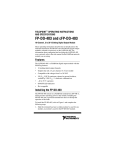
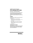
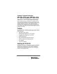
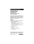
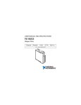
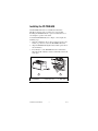
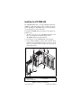
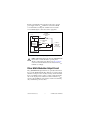
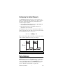
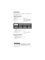
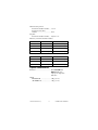
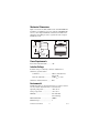
FIELDPOINT ™ OPERATING INSTRUCTIONS AND SPECIFICATIONS FP-PWM-520 and cFP-PWM-520 Eight-Channel, 5 V or 10–30 V PWM Output Module These operating instructions describe how to install and use the National Instruments FP-PWM-520 and cFP-PWM-520 pulse-width modulation modules (referred to inclusively as the [c]FP-PWM-520). For details on configuring and accessing the [c]FP-PWM-520 over a network, refer to the user manual for the FieldPoint network module you are using. Features The [c]FP-PWM-520 is a FieldPoint pulse-width modulation (PWM) output module with the following features: • Eight PWM sourcing output channels • 0 to 100% duty-cycle capability with 12-bit resolution • Short-circuit protection for outputs • Outputs source 5 VDC or 10–30 VDC with user-provided power supply • Independent configuration of the output period for each channel from 1 to 65,535 ms in 1 ms increments • On/Off LED indicators • 250 Vrms CAT II continuous channel-to-ground isolation, verified by 2,300 Vrms , 5 s dielectric withstand test • –40 to 70 °C operation • Hot swappable Installing the FP-PWM-520 The FP-PWM-520 mounts on a FieldPoint terminal base (FP-TB-x), which provides operating power to the module. Installing the FP-PWM-520 onto a powered terminal base does not disrupt the operation of the bank. To install the FP-PWM-520, refer to Figure 1 and complete the following steps: 1. Slide the terminal base key to either position X, used for any module, or position 4, used for the FP-PWM-520 module. 2. Align the FP-PWM-520 alignment slots with the guide rails on the terminal base. 3. Press firmly to seat the FP-PWM-520 on the terminal base. When the module is firmly seated, the terminal base latch locks it into place. 4 5 3 6 1 2 1 I/O Module 2 Terminal Base 3 Alignment Slot 4 Terminal Base Key 5 Latch 6 Guide Rails Figure 1. Installing the FP-PWM-520 FP-PWM-520 and cFP-PWM-520 2 ni.com Installing the cFP-PWM-520 The cFP-PWM-520 mounts on a Compact FieldPoint backplane (cFP-BP-x or cFP-180x), which provides operating power to the module. Installing the cFP-PWM-520 onto a powered backplane does not disrupt the operation of the bank. To install the cFP-PWM-520, refer to Figure 2 and complete the following steps: 1. Align the captive screws on the cFP-PWM-520 with the screw holes on the backplane. The alignment keys on the cFP-PWM-520 prevent backward insertion. 2. Press firmly to seat the cFP-PWM-520 on the backplane. 3. Using a number 2 Phillips screwdriver with a shank of at least 64 mm (2.5 in.) length, tighten the captive screws to 1.1 N ⋅ m (10 lb ⋅ in.) of torque. The nylon coating on the screws prevents them from loosening. 4 3 5 2 4 2 1 1 cFP I/O Module 2 Captive Screws 3 cFP Controller Module 4 Screw Holes 5 cFP Backplane Figure 2. Installing the cFP-PWM-520 © National Instruments Corp. 3 FP-PWM-520 and cFP-PWM-520 Wiring the [c]FP-PWM-520 The FP-TB-x terminal base has connections for each of the eight output channels and for an external power supply to power the output channels and field devices. The cFP-CB-x connector block provides the same connections. Each channel has one output terminal (VOUT ), one supply terminal (VSUP), and two common terminals (COM). All eight channels are referenced to the COM terminals. The V and VSUP terminals are all internally connected, as are the C and COM terminals. Table 1 lists the terminal assignments for the signals of each channel. Terminal assignments are also listed on the side panel of the cFP-PWM-520 and under the slide-in card on the front of the FP-PWM-520. Connect to the terminals using the terminal base, connector block, or other connectivity accessory. Table 1. Terminal Assignments Terminal Numbers Channel VOUT* VSUP† COM 0 1 17 2, 18 1 3 19 4, 20 2 5 21 6, 22 3 7 23 8, 24 4 9 25 10, 26 5 11 27 12, 28 6 13 29 14, 30 7 15 31 16, 32 * Install a 1 A maximum, fast-acting fuse on each VOUT terminal. † Install a 2 A maximum, fast-acting fuse on each V SUP terminal. Use a 5 VDC or 10–30 VDC external power supply for the output channels. The power supply must provide enough current to power all of the loads on the output channels, up to a maximum of 1 A per channel. Connect the external power supply to multiple V and VSUP terminals and to multiple C and COM terminals as needed to ensure that the maximum current through any terminal is 2 A or less. FP-PWM-520 and cFP-PWM-520 4 ni.com Install a 2 A maximum, fast-acting fuse between the external power supply and the VSUP terminal on each channel. Install a 1 A maximum, fast-acting fuse suitable for the load at the VOUT terminal. Figure 3 shows fuses where appropriate. C V VSUP Protected Sourcing Output 2 A Max User-Supplied Fuse 1 A Max User-Supplied Fuse VOUT 5 VDC or 10–30 VDC External – Power Supply + Load COM COM [c]FP-PWM-520 Figure 3. Wiring the [c]FP-PWM-520 Caution Maximum output current for the cFP-PWM-520 is lower than 1 A if the module is operating in the 50–70 °C temperature range. Refer to the Specifications section for more information, and select fuses for the VOUT terminals accordingly. Pulse-Width Modulator Output Circuit The [c]FP-PWM-520 output channels are optically isolated from the rest of the FieldPoint bank. The channels are sourcing outputs with short-circuit protection circuitry. Sourcing current means that the VOUT terminal provides a path to a voltage supply. In the ON state of the output period, a transistor is turned on between VSUP and VOUT. In the OFF state, this transistor is turned off, allowing only a small leakage current to flow. © National Instruments Corp. 5 FP-PWM-520 and cFP-PWM-520 In the ON state, the effective resistance between VOUT and VSUP causes a voltage drop between the external supply voltage and the output voltage. For example, if the external supply voltage is 5 V and the output current is 1 A, calculate the output voltage as follows: 5 V – (1 A × RON) = VOUT where RON is the ON resistance and VOUT is the output voltage. Refer to the Specifications section for the value of the ON resistance. Short-Circuit Protection If the protection circuitry detects a short-circuit condition on an output channel, it disables the output. If the protection circuitry disables an output that would otherwise be in the ON state, the status indicator for that channel is still lit, but the output transistor is turned off. Detecting a Short-Circuit Condition To determine whether a channel is in a short-circuit condition, complete the following steps: 1. In FieldPoint software, set the duty cycle to 100% for the channel in question. Refer to the Configuring the Output Channels section for more information about configuring the duty cycle. 2. Measure the voltage between the VOUT and VSUP terminals for that channel. Under normal load conditions, the VOUT -to-VSUP voltage is less than 1 V when the output is ON continuously. Any voltage higher than 1 V indicates a short circuit. Typically, the VOUT -to-COM voltage is almost zero if the protection circuitry is activated. Resetting a Channel in a Short-Circuit Condition To reset a channel in a short-circuit condition, you must first determine the cause of the condition and disconnect the load from the channel if necessary. When you have corrected the cause of the short-circuit condition, reset the channel in any of the following ways: • In FieldPoint software, set the duty cycle to 0%. The channel resets immediately. FP-PWM-520 and cFP-PWM-520 6 ni.com • Disconnect the external power supply from the [c]FP-PWM-520. • Remove the [c]FP-PWM-520 from the terminal base or backplane. • Power off or restart the network module connected to the [c]FP-PWM-520. Overcurrent Protection Each output channel on the [c]FP-PWM-520 has circuitry that protects it from current surges resulting from short circuits. Whether the module suffers damage from overcurrent conditions depends on the following factors: • The amount of current through the channel • The amount of time the current is above the current limit • The frequency of current surges If the level of current through the output terminal is higher than the guaranteed trip current for the module, the channel trips and goes into an overcurrent state. In an overcurrent state, the channel turns off and the module is not damaged. If the level of current through the output terminal is higher than the minimum possible trip current and lower than the guaranteed trip current, the state of the channel is indeterminate and depends on factors such as the current level, the temperature, and the power supply. Inrush currents that exist for less than the trip time do not trip the protection circuitry. Refer to the Specifications section for more information about the maximum continuous output current, trip current, and trip time. Power Supplies and Overcurrent Conditions If a short circuit occurs, the current through an output terminal can exceed the current rating for the power supply and the maximum continuous current for the [c]FP-PWM-520. If the power supply you are using with the [c]FP-PWM-520 cannot supply more than the guaranteed trip current, the module may be damaged if a short circuit occurs. © National Instruments Corp. 7 FP-PWM-520 and cFP-PWM-520 Configuring the Output Channels A [c]FP-PWM-520 output channel uses period and duty-cycle settings to determine when the channel is on or off. To configure the period, complete the following steps in Measurement & Automation Explorer (MAX): 1. On the Channel Configuration tab for the [c]FP-PWM-520, select Period from the Attribute menu. 2. Enter an integer between 1 ms (1 kHz) and 65,535 ms (0.01525 Hz) in the Value field. To configure the duty cycle, write to the channel for which you want to set the duty cycle. The duty cycle is the proportion of time that the PWM signal is ON over the period. OnTime Duty Cycle = --------------------- × 100 Period Enter a value from 0 to 100 to set the duty cycle. The duty cycle has 12-bit resolution (4,096 discrete duty-cycle settings). 2 2 VSUP 1 0 3 1 PWM Output 3 2 On Time 3 Period Figure 4. Period and Duty Cycle of a PWM Output Status Indicators The [c]FP-PWM-520 has two green status LEDs, POWER and READY. After you insert the FP-PWM-520 onto a terminal base or the cFP-PWM-520 onto a backplane and apply power to the connected network module, the green POWER indicator lights and the [c]FP-PWM-520 informs the network module of its presence. When the network module recognizes the FP-PWM-520 and cFP-PWM-520 8 ni.com [c]FP-PWM-520, it sends initial configuration information to the [c]FP-PWM-520. After the [c]FP-PWM-520 receives this initial information, the green READY indicator lights and the module is in normal operating mode. In addition to the green POWER and READY indicators, each channel has a numbered, green status LED that lights when the channel is in the ON state. Upgrading Your FieldPoint Firmware You may need to upgrade your FieldPoint firmware when you add new I/O modules to your FieldPoint system. For information on determining which firmware you need and how to upgrade your firmware, go to ni.com/info and enter fpmatrix. Isolation and Safety Guidelines Read the following information before attempting to connect the [c]FP-PWM-520 to any circuits that may contain hazardous voltages. Caution This section describes the isolation of the [c]FP-PWM-520 and its compliance with international safety standards. The field wiring connections are isolated from the backplane and the inter-module communication bus. The isolation barriers in the module provide 250 Vrms Measurement Category II continuous isolation, verified by 2,300 Vrms , 5 s dielectric withstand test. The [c]FP-PWM-520 provides double insulation (compliant with IEC 61010-1) for working voltages of 250 Vrms1. Safety standards (such as those published by UL and IEC) require the use of double insulation between hazardous voltages and any human-accessible parts or circuits. Never try to use any isolation product between human-accessible parts (such as DIN rails or monitoring stations) and circuits that can be at hazardous potentials under normal conditions, unless the product is specifically designed for such an application, as is the [c]FP-PWM-520. 1 Working voltage is defined as the signal voltage plus the common-mode voltage. Common-mode voltage is the voltage of the module with respect to ground. © National Instruments Corp. 9 FP-PWM-520 and cFP-PWM-520 Even though the [c]FP-PWM-520 is designed to handle applications with hazardous potentials, follow these guidelines to ensure a safe total system: • There is no isolation between channels on the [c]FP-PWM-520. If a hazardous voltage is present on any channel, all channels are considered hazardous. Make sure that all other devices and circuits connected to the module are properly insulated from human contact. • Do not share the external supply voltages (the V and C terminals) with other devices (including other FieldPoint devices), unless those devices are isolated from human contact. • For Compact FieldPoint, you must connect the protective earth (PE) ground terminal on the cFP-BP-x backplane to the system safety ground. The backplane PE ground terminal has the following symbol stamped beside it: . Connect the backplane PE ground terminal to the system safety ground using 14 AWG (1.6 mm) wire with a ring lug. Use the 5/16 in. panhead screw shipped with the backplane to secure the ring lug to the backplane PE ground terminal. • As with any hazardous voltage wiring, make sure that all wiring and connections meet applicable electrical codes and commonsense practices. Mount terminal bases and backplanes in an area, position, or cabinet that prevents accidental or unauthorized access to wiring that carries hazardous voltages. • Do not use the [c]FP-PWM-520 as the only isolating barrier between human contact and working voltages higher than 250 Vrms . • Operate the [c]FP-PWM-520 only at or below Pollution Degree 2. Pollution Degree 2 means that only nonconductive pollution occurs in most cases. Occasionally, however, a temporary conductivity caused by condensation must be expected. • Operate the [c]FP-PWM-520 at or below Measurement Category II. Measurement Category II is for measurements performed on circuits directly connected to the low-voltage installation. This category refers to local-level distribution, such as that provided by a standard wall outlet. FP-PWM-520 and cFP-PWM-520 10 ni.com Safety Guidelines for Hazardous Locations The cFP-PWM-520 is suitable for use in Class I, Division 2, Groups A, B, C, D, T4 hazardous locations; Class I, Zone 2, AEx nC IIC T4 and Ex nC IIC T4 hazardous locations; and nonhazardous locations only. Follow these guidelines if you are installing the cFP-PWM-520 in a potentially explosive environment. Failing to follow these guidelines may result in serious injury or death. Caution Make sure that all products you use in hazardous locations are certified for such use. Refer to the product label or visit ni.com/certification, search by model number or product line, and click the appropriate link in the Certification column. Caution Do not disconnect I/O-side wires or connectors unless power has been switched off or the area is known to be nonhazardous. Caution Do not remove modules unless power has been switched off or the area is known to be nonhazardous. Substitution of components may impair suitability for Class I, Division 2. Caution For Zone 2 applications, install the Compact FieldPoint system in an enclosure rated to at least IP 54 as defined by IEC 60529 and EN 60529. Caution For Zone 2 applications, install a protection device across the external power supply and the COM terminal. The device must prevent the external power supply voltage from exceeding 42 V if there is a transient overvoltage condition. Caution Special Conditions for Hazardous Locations Use in Europe The cFP-PWM-520 has been evaluated as EEx nC IIC T4 equipment under DEMKO Certificate No. 03 ATEX 0251502X. Each module is marked II 3G and is suitable for use in Zone 2 hazardous locations. © National Instruments Corp. 11 FP-PWM-520 and cFP-PWM-520 Specifications The following specifications are typical for a range of –40 to 70 °C unless otherwise noted. Output Characteristics Number of channels.......................... 8 Output type ....................................... Sourcing Output voltage .................................. Supply voltage – (Output current × Output impedance) Supply voltage .................................. 5 VDC or 10 to 30 VDC, user-provided Maximum output current per channel Temperature Ranges Module –40 to 50 °C 50 to 60 °C 60 to 70 °C cFP-PWM-520 1A 0.75 A 0.5 A FP-PWM-520 1A 1A 1A ON resistance Revision E and later modules1 ... 0.15 Ω Revision D and earlier modules ...................................... 0.3 Ω Pulse-width accuracy ........................ –1, +3 μs, any period and duty cycle Short-Circuit Protection Minimum trip current Revision E and later modules..... 9 A Revision D and earlier modules ...................................... 1 A 1 The letter in the part number identifies the revision of the module. For example, part number 185715A-02 identifies a revision A cFP-PWM-520. The part number is printed on a label on the module. On the FP-PWM-520, the label is on the bottom of the module. On the cFP-PWM-520, the label is on the back of the module. FP-PWM-520 and cFP-PWM-520 12 ni.com Guaranteed trip current Revision E and later modules..... 12.5 A Revision D and earlier modules ...................................... 20 A Trip time Revision E and later modules..... 10 μs at 13 A Behavior (revision E and later modules) Current Level Channel Behavior Module Protection 0–1 A Channel does not trip Module is not damaged 1–9 A Channel does not trip Module may be damaged 9–12.5 A Channel may trip Module may be damaged 12.5 A Channel trips Module is not damaged Behavior (revision D and earlier modules) Current Level Channel Behavior Module Protection 0–1 A Channel does not trip Module is not damaged 1–20 A Channel may trip Module may be damaged ≥20 A Channel trips Module is not damaged Physical Characteristics Indicators .......................................... Green POWER and READY indicators, eight green output state indicators Weight FP-PWM-520 ............................. 140 g (4.9 oz) cFP-PWM-520 ........................... 110 g (3.9 oz) © National Instruments Corp. 13 FP-PWM-520 and cFP-PWM-520 Mechanical Dimensions Figure 5 shows the mechanical dimensions of the FP-PWM-520 installed on a terminal base. If you are using the cFP-PWM-520, refer to your Compact FieldPoint controller user manual for the dimensions and cabling clearance requirements of the Compact FieldPoint system. 107.19 mm (4.22 in.) 109.5 mm (4.31 in.) 91.44 mm (3.60 in.) Figure 5. FP-PWM-520 Mechanical Dimensions Power Requirements Power from network module ............ 1 W Isolation Voltage Isolation voltage is verified by a dielectric withstand test. Channel-to-ground isolation Continuous ................................. 250 Vrms, Measurement Category II Dielectric withstand.................... 2,300 Vrms, 5 s max Channel-to-channel isolation ............ None Environmental FieldPoint modules are intended for indoor use only. For outdoor use, they must be mounted inside a sealed enclosure. Operating temperature ...................... –40 to 70 °C Storage temperature .......................... –55 to 85 °C Humidity ........................................... 10 to 90% RH, noncondensing Maximum altitude............................. 2,000 m Pollution Degree ............................... 2 FP-PWM-520 and cFP-PWM-520 14 ni.com Shock and Vibration These specifications apply only to the cFP-PWM-520. NI recommends Compact FieldPoint if your application is subject to shock and vibration. Operating vibration, random (IEC 60068-2-64).............................. 10–500 Hz, 5 grms Operating vibration, sinusoidal (IEC 60068-2-6)................................ 10–500 Hz, 5 g Operating shock (IEC 60068-2-27).............................. 50 g, 3 ms half sine, 18 shocks at 6 orientations; 30 g, 11 ms half sine, 18 shocks at 6 orientations Hazardous Locations U.S. (UL) .......................................... Class I, Division 2, Groups A, B, C, D, T4; Class I, Zone 2, AEx nC IIC T4 Canada (C-UL) ................................. Class I, Division 2, Groups A, B, C, D, T4; Class I, Zone 2, Ex nC IIC T4 Europe (DEMKO)............................. Ex nC IIC T4 Safety This product is designed to meet the requirements of the following standards of safety for electrical equipment for measurement, control, and laboratory use: • IEC 61010-1, EN 61010-1 • UL 61010-1, CSA 61010-1 Note For UL and other safety certifications, refer to the product label or visit ni.com/certification, search by model number or product line, and click the appropriate link in the Certification column. © National Instruments Corp. 15 FP-PWM-520 and cFP-PWM-520 Electromagnetic Compatibility This product is designed to meet the requirements of the following standards of EMC for electrical equipment for measurement, control, and laboratory use: • EN 61326 EMC requirements; Industrial Immunity • EN 55011 Emissions; Group 1, Class A • CE, C-Tick, ICES, and FCC Part 15 Emissions; Class A Note For EMC compliance, operate this device according to product documentation. CE Compliance This product meets the essential requirements of applicable European Directives, as amended for CE marking, as follows: • 2006/95/EC; Low-Voltage Directive (safety) • 2004/108/EC; Electromagnetic Compatibility Directive (EMC) Note Refer to the Declaration of Conformity (DoC) for this product for any additional regulatory compliance information. To obtain the DoC for this product, visit ni.com/certification, search by model number or product line, and click the appropriate link in the Certification column. Environmental Management National Instruments is committed to designing and manufacturing products in an environmentally responsible manner. NI recognizes that eliminating certain hazardous substances from our products is beneficial not only to the environment but also to NI customers. For additional environmental information, refer to the NI and the Environment Web page at ni.com/environment. This page contains the environmental regulations and directives with which NI complies, as well as other environmental information not included in this document. FP-PWM-520 and cFP-PWM-520 16 ni.com Waste Electrical and Electronic Equipment (WEEE) EU Customers At the end of their life cycle, all products must be sent to a WEEE recycling center. For more information about WEEE recycling centers and National Instruments WEEE initiatives, visit ni.com/ environment/weee.htm. ⬉ᄤֵᙃѻક∵ᶧࠊㅵ⧚ࡲ⊩ ˄Ё RoHS˅ Ёᅶ᠋ National Instruments ヺড়Ё⬉ᄤֵᙃ ѻકЁ䰤ࠊՓ⫼ᶤѯ᳝ᆇ⠽䋼ᣛҸ (RoHS)DŽ݇Ѣ National Instruments Ё RoHS ড়㾘ᗻֵᙃˈ䇋ⱏᔩ ni.com/environment/rohs_chinaDŽ (For information about China RoHS compliance, go to ni.com/ environment/rohs_china.) © National Instruments Corp. 17 FP-PWM-520 and cFP-PWM-520 Where to Go for Support For more information about setting up the FieldPoint system, refer to these National Instruments documents: • FieldPoint network module user manual • Other FieldPoint I/O module operating instructions • FieldPoint terminal base and connector block operating instructions Go to ni.com/support for the most current manuals, examples, and troubleshooting information. For telephone support in the United States, create your service request at ni.com/ask and follow the calling instructions or dial 512 795 8248. For telephone support outside the United States, contact your local branch office: Australia 1800 300 800, Austria 43 662 457990-0, Belgium 32 (0) 2 757 0020, Brazil 55 11 3262 3599, Canada 800 433 3488, China 86 21 5050 9800, Czech Republic 420 224 235 774, Denmark 45 45 76 26 00, Finland 358 (0) 9 725 72511, France 01 57 66 24 24, Germany 49 89 7413130, India 91 80 41190000, Israel 972 3 6393737, Italy 39 02 41309277, Japan 0120-527196, Korea 82 02 3451 3400, Lebanon 961 (0) 1 33 28 28, Malaysia 1800 887710, Mexico 01 800 010 0793, Netherlands 31 (0) 348 433 466, New Zealand 0800 553 322, Norway 47 (0) 66 90 76 60, Poland 48 22 3390150, Portugal 351 210 311 210, Russia 7 495 783 6851, Singapore 1800 226 5886, Slovenia 386 3 425 42 00, South Africa 27 0 11 805 8197, Spain 34 91 640 0085, Sweden 46 (0) 8 587 895 00, Switzerland 41 56 2005151, Taiwan 886 02 2377 2222, Thailand 662 278 6777, Turkey 90 212 279 3031, United Kingdom 44 (0) 1635 523545 FP-PWM-520 and cFP-PWM-520 18 ni.com National Instruments, NI, ni.com, and LabVIEW are trademarks of National Instruments Corporation. Refer to the Terms of Use section on ni.com/legal for more information about National Instruments trademarks. Other product and company names mentioned herein are trademarks or trade names of their respective companies. For patents covering National Instruments products, refer to the appropriate location: Help»Patents in your software, the patents.txt file on your media, or ni.com/patents. © 2002–2008 National Instruments Corp. All rights reserved. 373357E-01 Jun08

![[c]FP-DO-401 Operating Instructions](http://vs1.manualzilla.com/store/data/005693758_1-4b10a2df6965457ee651014d1377996a-150x150.png)