1
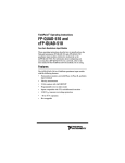
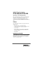
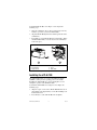
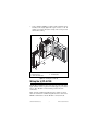
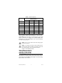
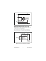
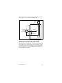
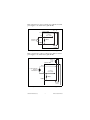
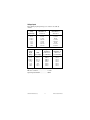
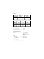
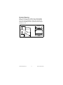
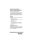
FieldPoint™ Operating Instructions
FP-AI-100 and cFP-AI-100
Eight-Channel, 12-Bit Analog Input Modules
These operating instructions describe how to install and use the
FP-AI-100 and cFP-AI-100 analog input modules (referred to
inclusively as the [c]FP-AI-100). For information about
configuring and accessing the [c]FP-AI-100 over a network,
refer to the user manual for the FieldPoint network module you are
using.
Features
The [c]FP-AI-100 is a FieldPoint analog input module with the
following features:
•
Eight analog voltage or current input channels
•
11 input ranges: 0–1 V, 0–5 V, 0–15 V, 0–30 V, ±1 V, ±5 V,
±15 V, ±30 V, 0–20 mA, 4–20 mA, and ±20 mA
•
12-bit resolution
•
250 Vrms CAT II continuous channel-to-ground isolation,
verified by 2,300 Vrms ,1 minute dielectric withstand test
•
–40 to 70 °C operation
•
Hot swappable
Installing the FP-AI-100
The FP-AI-100 mounts on a FieldPoint terminal base (FP-TB-x),
which provides operating power to the module. Installing the
FP-AI-100 onto a powered terminal base does not disrupt the
operation of the FieldPoint bank.
To install the FP-AI-100, refer to Figure 1 and complete the
following steps:
1. Slide the terminal base key to either position X (used for any
module) or position 1 (used for the FP-AI-100).
2. Align the FP-AI-100 alignment slots with the guide rails on the
terminal base.
3. Press firmly to seat the FP-AI-100 on the terminal base. When
the FP-AI-100 is firmly seated, the latch on the terminal base
locks it into place.
4
5
3
6
1
2
1 I/O Module
2 Terminal Base
3 Alignment Slot
4 Key
5 Latch
6 Guide Rails
Figure 1. Installing the FP-AI-100
Installing the cFP-AI-100
The cFP-AI-100 mounts on a Compact FieldPoint backplane
(cFP-BP-x), which provides operating power to the module.
Installing the cFP-AI-100 onto a powered backplane does not
disrupt the operation of the FieldPoint bank.
To install the cFP-AI-100, refer to Figure 2 and complete the
following steps:
1. Align the captive screws on the cFP-AI-100 with the holes on
the backplane. The alignment keys on the cFP-AI-100 prevent
backward insertion.
2. Press firmly to seat the cFP-AI-100 on the backplane.
FP-AI-100 and cFP-AI-100
2
ni.com
3. Using a number 2 Phillips screwdriver with a shank of at least
64 mm (2.5 in.) length, tighten the captive screws to 1.1 N ⋅ m
(10 lb ⋅ in.) of torque. The nylon coating on the screws prevents
them from loosening.
4
3
5
2
4
2
1
1 cFP-AI-100
2 Captive Screws
3 cFP Controller Module
4 Screw Holes
5 cFP Backplane
Figure 2. Installing the cFP-AI-100
Wiring the [c]FP-AI-100
The FP-TB-x terminal base has connections for each of the eight
input channels and for an optional external supply to power field
devices. The cFP-CB-x connector block provides the same
connections.
Table 1 lists the terminal assignments for the signals associated
with each channel. The terminal assignments are the same for the
FP-TB-x terminal bases and the cFP-CB-x connector blocks.
© National Instruments Corp.
3
FP-AI-100 and cFP-AI-100
Table 1. Terminal Assignments
Terminal Numbers
Channel
Vin
Iin
Vsup
COM
0
1
2
17
18
1
3
4
19
20
2
5
6
21
22
3
7
8
23
24
4
9
10
25
26
5
11
12
27
28
6
13
14
29
30
7
15
16
31
32
Each channel has separate input terminals for voltage (Vin) and
current (Iin) input. Voltage and current inputs are referenced to the
COM terminals. If you are using an external supply to power field
devices, connect the power supply to the V and C terminals of the
terminal base or connector block. Refer to the sections that follow
for detailed wiring diagrams.
Caution Do not connect both current and voltage inputs
to the same channel.
Cascading power between two modules defeats
isolation between those modules. Cascading power from
the network module defeats all isolation between
modules in the FieldPoint bank.
Caution
Taking Measurements
with the [c]FP-AI-100
The [c]FP-AI-100 has eight single-ended input channels. All eight
channels share a common ground reference that is isolated from
other modules in the FieldPoint system. Figure 3 shows the analog
input circuitry on one channel.
FP-AI-100 and cFP-AI-100
4
ni.com
V
VSUP
Vin
Filter
12-Bit
Isolated ADC
Iin
Filter
COM
C
Figure 3. [c]FP-AI-100 Analog Input Circuit, One Channel
Measuring Voltage with the [c]FP-AI-100
The input ranges for voltage signals are 0–1 V, 0–5 V, 0–15 V,
0–30 V, ±1 V, ±5 V, ±15 V, and ±30 V.
Figure 4 shows how to connect a voltage source without an
external power supply to one channel of the [c]FP-AI-100.
[c]FP-AI-100
C
V
Vsup
To Analog
Input Circuitry
Vin
Voltage
Source
1.5 MΩ
Input
Impedance
+
–
COM
To Next
Channel
Figure 4. Voltage Source without External Power Supply
© National Instruments Corp.
5
FP-AI-100 and cFP-AI-100
Figure 5 shows how to connect a voltage source with an external
power supply to one channel of the [c]FP-AI-100.
External
Power
Supply
[c]FP-AI-100
+
–
C
V
Vsup
Powered
Voltage
Transducer
+
OUT
To Analog
Input Circuitry
Vin
–
1.5 MΩ
Input
Impedance
COM
To Next
Channel
Figure 5. Voltage Source with External Power Supply
Measuring Current with the [c]FP-AI-100
The input ranges for current sources are 0–20, 4–20, and ±20 mA.
The module reads current flowing into the Iin terminal as positive
and current flowing out of the terminal as negative. Current flows
into the Iin terminal, goes through a 100 Ω resistor, and flows out
from the COM or C terminal.
FP-AI-100 and cFP-AI-100
6
ni.com
Figure 6 shows how to connect a current source without an external
power supply to one channel of the [c]FP-AI-100.
C
[c]FP-AI-100
V
Vsup
To Analog
Input Circuitry
Iin
Current
Source
100 Ω
COM
To Next
Channel
Figure 6. Current Source without External Power Supply
Figure 7 shows how to connect a current source with an external
power supply to one channel of the [c]FP-AI-100.
External
Power
Supply
[c]FP-AI-100
+
–
C
V
Vsup
Loop-Powered
Current
Transducer
To Analog
Input Circuitry
Iin
100 Ω
COM
To Next
Channel
Figure 7. Current Source with External Power Supply
© National Instruments Corp.
7
FP-AI-100 and cFP-AI-100
Input Ranges
To prevent inaccurate readings, choose an input range such that the
signal you are measuring does not exceed either end of the range.
If a channel is not in use, short the positive input to ground and
configure the channel for a bipolar input range. Small fluctuations
in floating input signals can cause the red Out of Range status
LED on the module to light if the channel is configured for a
unipolar range. Similarly, if a channel is configured for 4–25 mA
input and the input current is 0 mA, the channel is always out of
range.
Overranging
The [c]FP-AI-100 has an overranging feature that measures a little
beyond the nominal values of each range. For example, the actual
measurement limit of the ±5 V range is ±6.0 V. The overranging
feature allows the [c]FP-AI-100 to compensate for field devices
with span errors of up to +20% of full scale. Also, with the
overranging feature, a noisy signal near full scale does not create
rectification errors.
Status Indicators
The [c]FP-AI-100 has two green status LEDs, POWER and
READY. After you insert the [c]FP-AI-100 into a terminal base
or backplane and apply power to the connected network module,
the green POWER indicator lights and the [c]FP-AI-100 informs
the network module of its presence. When the network module
recognizes the [c]FP-AI-100, it sends initial configuration
information to the [c]FP-AI-100. After the [c]FP-AI-100 receives
this initial information, the green READY indicator lights and the
module is in normal operating mode.
In addition to the green POWER and READY indicators, the
[c]FP-AI-100 has one red status LED that lights when the input
signal on any channel is outside the configured range. Refer to the
Input Ranges section for information about selecting input ranges.
Upgrading the FieldPoint Firmware
You may need to upgrade the FieldPoint firmware when you add
new I/O modules to the FieldPoint system. For information on
determining which firmware you need and how to upgrade the
firmware, go to ni.com/info and enter fpmatrix.
FP-AI-100 and cFP-AI-100
8
ni.com
Isolation and Safety Guidelines
Read the following information before
attempting to connect the [c]FP-AI-100 to any circuits
that may contain hazardous voltages.
Caution
This section describes the isolation of the [c]FP-AI-100 and its
compliance with international safety standards. The field wiring
connections are isolated from the backplane and the inter-module
communication bus. The isolation barriers in the module provide
250 Vrms Installation Category II continuous isolation, verified by
2,300 Vrms , 1 minute dielectric withstand test. The [c]FP-AI-100
provides double insulation (compliant with IEC 61010-1) for
working voltages of 250 Vrms1. Safety standards (such as those
published by UL and IEC) require the use of double insulation
between hazardous voltages and any human-accessible parts or
circuits.
Never try to use any isolation product between human-accessible
parts (such as DIN rails or monitoring stations) and circuits that
can be at hazardous potentials under normal conditions, unless the
product is specifically designed for such an application, as is the
[c]FP-AI-100.
Even though the [c]FP-AI-100 is designed to handle applications
with hazardous potentials, follow these guidelines to ensure a safe
total system:
•
There is no isolation between channels on the [c]FP-AI-100.
If a hazardous voltage is present on any channel, all channels
are considered hazardous. Make sure that all other devices and
circuits connected to the module are properly insulated from
human contact.
•
Do not share the external supply voltages (the V and C
terminals) with other devices (including other FieldPoint
devices), unless those devices are isolated from human contact.
•
For Compact FieldPoint, you must connect the protective earth
(PE) ground terminal on the cFP-BP-x backplane to the system
safety ground. The backplane PE ground terminal has the
following symbol stamped beside it: . Connect the
1
Working voltage is defined as the signal voltage plus the common-mode voltage.
Common-mode voltage is the voltage of the module with respect to ground.
© National Instruments Corp.
9
FP-AI-100 and cFP-AI-100
backplane PE ground terminal to the system safety ground
using 14 AWG (1.6 mm) wire with a ring lug. Use the 5/16 in.
panhead screw shipped with the backplane to secure the ring
lug to the backplane PE ground terminal.
•
As with any hazardous voltage wiring, make sure that all
wiring and connections meet applicable electrical codes and
commonsense practices. Mount terminal bases and backplanes
in an area, position, or cabinet that prevents accidental or
unauthorized access to wiring that carries hazardous voltages.
•
Do not use the [c]FP-AI-100 as the only isolating barrier
between human contact and working voltages higher than
250 Vrms .
•
Operate the [c]FP-AI-100 only at or below Pollution Degree 2.
Pollution Degree 2 means that only nonconductive pollution
occurs in most cases. Occasionally, however, a temporary
conductivity caused by condensation must be expected.
•
Do not operate FieldPoint products in an explosive atmosphere
or where there may be flammable gases or fumes. If you need
to operate FieldPoint products in such an environment, the
FieldPoint products must be in a suitably rated enclosure.
•
Operate the [c]FP-AI-100 at or below Installation Category II.
Installation Category II is for measurements performed on
circuits directly connected to the low-voltage installation.
This category refers to local-level distribution, such as that
provided by a standard wall outlet.
Specifications
The following specifications are typical for the range –40 to 70 °C
unless otherwise noted. Gain error is calculated as a percentage of
input signal value.
Input Characteristics
Number of channels.......................... 8
ADC resolution................................. 12 bits
Type of ADC..................................... Successive approximation
Update rate (all channels) ................. 360 Hz (2.8 ms)
FP-AI-100 and cFP-AI-100
10
ni.com
Voltage Inputs
The following input signal ranges are software selectable by
channel.
Voltage
Input Range
Typical
Offset Error at
15 to 35 °C
Maximum
Offset Error at
–40 to 70 °C
0–1 V
0–5 V
0–15 V
0–30 V
±1 V
±5 V
±15 V
±30 V
2.9 mV
6.5 mV
13 mV
17.5 mV
3.6 mV
9.5 mV
21.8 mV
35.1 mV
9.3 mV
17.2 mV
30 mV
33.3 mV
10.3 mV
23 mV
44.7 mV
62.5 mV
Voltage
Input
Range
0–1 V
0–5 V
0–15 V
0–30 V
±1 V
±5 V
±15 V
±30 V
With
Overranging
Typical
Gain Error
at 15 to 35 °C
(% of Reading)
Maximum
Gain Error at
–40 to 70 °C
(% of Reading)
0–1.2 V
0–6 V
0–18 V
0–36 V
±1.2 V
±6 V
±18 V
±36 V
0.065%
0.065%
0.065%
0.065%
0.07%
0.07%
0.07%
0.07%
0.19%
0.19%
0.19%
0.19%
0.22%
0.22%
0.22%
0.22%
Input impedance................................ 1.5 MΩ
Effective resolution........................... 11.3 bits
Signal input bandwidth ..................... 170 Hz
© National Instruments Corp.
11
FP-AI-100 and cFP-AI-100
Current Inputs
The following input signal ranges are software selectable by
channel.
Current
Input Range
Typical
Offset Error at
15 to 35 °C
Maximum
Offset Error at
–40 to 70 °C
0–20 mA
4–20 mA
±20 mA
12 µΑ
12 µΑ
23 µΑ
20 µΑ
20 µΑ
40 µΑ
Current
Input
Range
0–20 mA
4–20 mA
±20 mA
With
Overranging
Typical
Gain Error at
15 to 35 °C
(% of Reading)
Maximum
Gain Error at
–40 to 70 °C
(% of Reading)
0–24 mA
3.5–24 mA
±24 mA
0.083%
0.083%
0.09%
0.32%
0.32%
0.35%
Input impedance................................ 100 Ω
Overcurrent protection...................... ±30 mA
Effective resolution........................... 11.5 bits
Signal input bandwidth ..................... 160 Hz
Physical Characteristics
Indicators .......................................... Green POWER and
READY indicators;
one red Out of Range
indicator
Weight
FP-AI-100................................... 145 g (5.1 oz)
cFP-AI-100................................. 115 g (4.0 oz)
Power Requirement
Power from network module ............ 400 mW
FP-AI-100 and cFP-AI-100
12
ni.com
Isolation Voltage
Channel-to-ground isolation
Continuous ................................. 250 Vrms,
Installation Category II
Dielectric withstand.................... 2,300 Vrms , 1 minute
Channel-to-channel isolation ............ None
Environmental
FieldPoint modules are intended for indoor use only. For outdoor
use, they must be mounted inside a sealed enclosure.
Operating temperature ...................... –40 to 70 °C
Storage temperature .......................... –55 to 85 °C
Humidity ........................................... 10 to 90% RH,
noncondensing
Maximum altitude............................. 2,000 m; at higher altitudes
the isolation voltage ratings
must be lowered.
Pollution Degree ............................... 2
Shock and Vibration
These specifications apply only to the cFP-AI-100.
NI recommends Compact FieldPoint if your application
is subject to shock and vibration.
Operating vibration, random
(IEC 60068-2-64).............................. 10–500 Hz, 5 grms
Operating vibration, sinusoidal
(IEC 60068-2-6)................................ 10–500 Hz, 5 g
Operating shock
(IEC 60068-2-27).............................. 50 g, 3 ms half sine,
18 shocks at 6 orientations;
30 g, 11 ms half sine,
18 shocks at 6 orientations
© National Instruments Corp.
13
FP-AI-100 and cFP-AI-100
Safety
This product is designed to meet the requirements of the following
standards of safety for electrical equipment for measurement,
control, and laboratory use:
•
IEC 61010-1, EN 61010-1
•
UL 61010-1
•
CAN/CSA-C22.2 No. 61010-1
Note For UL, hazardous locations, and other safety
certifications, refer to the product label, or visit
ni.com/certification, search by model number or
product line, and click the appropriate link in the
Certification column.
Electromagnetic Compatibility
Emissions.......................................... EN 55011 Class A at 10 m
FCC Part 15A above 1 GHz
Immunity........................................... EN 61326:1997 + A2:2001,
Table 1
CE, C-Tick, and FCC Part 15 (Class A) Compliant
Note For EMC compliance, operate this device with
shielded cabling.
CE Compliance
This product meets the essential requirements of applicable
European Directives, as amended for CE marking, as follows:
Low-Voltage Directive (safety)......... 73/23/EEC
Electromagnetic Compatibility
Directive (EMC) ............................... 89/336/EEC
Note Refer to the Declaration of Conformity (DoC) for
this product for any additional regulatory compliance
information. To obtain the DoC for this product, visit
ni.com/certification, search by model number or
product line, and click the appropriate link in the
Certification column.
FP-AI-100 and cFP-AI-100
14
ni.com
Mechanical Dimensions
Figure 8 shows the mechanical dimensions of the FP-AI-100
installed on a terminal base. If you are using the cFP-AI-100,
refer to the Compact FieldPoint controller user manual for the
dimensions and cabling clearance requirements of the Compact
FieldPoint system.
107.19 mm
(4.22 in.)
109.5 mm
(4.31 in.)
91.44 mm
(3.60 in.)
Figure 8. FP-AI-100 Mechanical Dimensions
© National Instruments Corp.
15
FP-AI-100 and cFP-AI-100
Where to Go for Support
For more information about setting up the FieldPoint system, refer
to these National Instruments documents:
•
FieldPoint network module user manual
•
Other FieldPoint I/O module operating instructions
•
FieldPoint terminal base and connector block operating
instructions
Go to ni.com/support for the most current manuals, examples,
and troubleshooting information.
National Instruments corporate headquarters is located at 11500
North Mopac Expressway, Austin, Texas, 78759-3504. National
Instruments also has offices located around the world to help
address your support needs. For telephone support in the United
States, create your service request at ni.com/support and follow
the calling instructions or dial 512 795 8248. For telephone
support outside the United States, contact your local branch office:
Australia 1800 300 800, Austria 43 0 662 45 79 90 0,
Belgium 32 0 2 757 00 20, Brazil 55 11 3262 3599,
Canada (Calgary) 403 274 9391, Canada (Ottawa) 613 233 5949,
Canada (Québec) 450 510 3055, Canada (Toronto) 905 785 0085,
Canada (Vancouver) 604 685 7530, China 86 21 6555 7838,
Czech Republic 420 224 235 774, Denmark 45 45 76 26 00,
Finland 385 0 9 725 725 11, France 33 0 1 48 14 24 24,
Germany 49 0 89 741 31 30, India 91 80 51190000,
Israel 972 0 3 6393737, Italy 39 02 413091,
Japan 81 3 5472 2970, Korea 82 02 3451 3400,
Malaysia 603 9131 0918, Mexico 01 800 010 0793,
Netherlands 31 0 348 433 466, New Zealand 0800 553 322,
Norway 47 0 66 90 76 60, Poland 48 22 3390150,
Portugal 351 210 311 210, Russia 7 095 783 68 51,
Singapore 65 6226 5886, Slovenia 386 3 425 4200,
South Africa 27 0 11 805 8197, Spain 34 91 640 0085,
Sweden 46 0 8 587 895 00, Switzerland 41 56 200 51 51,
Taiwan 886 2 2528 7227, Thailand 662 992 7519,
United Kingdom 44 0 1635 523545
FieldPoint™, National Instruments™, NI™, and ni.com™ are trademarks of National Instruments Corporation.
Product and company names mentioned herein are trademarks or trade names of their respective companies.
For patents covering National Instruments products, refer to the appropriate location: Help»Patents in your software,
the patents.txt file on your CD, or ni.com/patents.
© 2002–2004 National Instruments Corp. All rights reserved.
*370278A-01*
370278A-01
Jul04


![[c]FP-DO-401 Operating Instructions](http://vs1.manualzilla.com/store/data/005693758_1-4b10a2df6965457ee651014d1377996a-150x150.png)