1
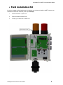
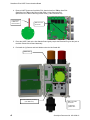
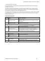
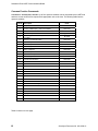
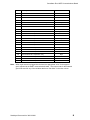
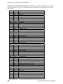
HART Communications Board (Highway Addressable Remote Transducer) User Manual Document No. 360-0128-01 (Revision C) Sensidyne, LP. 1000 112th Circle N, Suite 100 St. Petersburg, Florida 33716 USA 800-451-9444 • +1 727-530-3602 • +1 727-539-0550 [fax] web: www.sensidyne.com • e-mail: [email protected] SensAlarm Plus HART Communications Board Field Installation Kit If you have ordered the field install kit p/n 821-0302-02, you will need to install the HART Card into your SensAlarm Plus Monitor as follows (If not skip to Set Up): 1. Disconnect Power - Open cover. 2. Remove screws from Main PCA. 3. Install (3) Hex Stand-offs on Main PCA. Stand-Offs (3 Places) Sensidyne Document No. 360-0128-01 3 SensAlarm Plus HART Communications Board 4. Remove HART Connector from Main PCA. Attach wires from TB9 on Hart PCA (Red Wire from TB9 on Hart Plug to Main PCA (+) Hart Connector Pin) (Black Wire from TB9 on Hart Plug to Main PCA (-) Hart Connector Pin) Connect Wires to Main PCA Hart Connector Main PCA Hart Connector 5. Place the HART Card on the Hex Stand-offs and gently couple the Electrical Plug into the jack on the Main Printed Circuit Board Assembly. 6. Re-Install the (3) Screws and Lock-Washers into the Hex Stand-offs. HART Card Screws & Washers (3 Places) (from Main PCA) Main PCA HART Connector. (+) Red Wire (-) Black Wire 4 Sensidyne Document No. 360-0128-01 SensAlarm Plus HART Communications Board • Refer to SensAlarm Plus User Manual (P/N: 360-0126-01) The following section is reprinted from the SensAlarm Plus User Manual. A properly installed HART Communication Board will indicate Hart Comm at step 5.2.5.5. If “Modbus Comm.” Or “No Comm Installed” appears, an improper Board has been installed in the monitor. 5.2 Main Menu As shown on the example display to the right, the top level (main) menu allows the selection of several submenus, documented below. Selecting OK brings up the submenus. Main Menu > Calibration Mode Calibration Mode MaintenanceMode Mode Maintenance Data Review Data Review Test-on-Demand Test On Demand System Config > System Configuration Lost Password System Configuration 5.2.5 System Configuration The System Configuration menu provides a large number of functions for configuring the operation of the unit. These include conducting a self test, alarm and relay setup, adjusting the 4 mA & 20 mA outputs, setting the date and time, communications setup, adjusting TOD cell functions, setting combustible sensor parameters, and setting a password. Calibration Mode >> Self Test Maintenance Alarm Settings Mode 4/20 mA Adjustment Data Review Adjust Date/Time Test-on-Demand Communication Setup System TOD ModeConfig Adjustment --more-- Communication Setup > Calibration Mode 5.2.5.5 Communication Setup This menu provides adjustment for both standard and optional installed communications methods. Options installed will be displayed. Possible options are Hart Comm Modbus Comm Maintenance Mode > 4/20mA Communication Data Review Modbus Comm Test-on-Demand System Config (If no Communications Option is installed Display will read) No Comm Installed Modbus Comm > Calibration Mode Modbus Address Maintenance Mode Baud Rate Data Review Parity Test-on-Demand Stop Bits System Config Sensidyne Document No. 360-0128-01 5 SensAlarm Plus HART Communications Board 5.2.3 Data Review Data review allows the examination of data stored by the unit. Data reviews are available for the Test-On-Demand gas generating cell, the installed sensor, Fault Currents, Active Alarms/Faults, Rly Alm Fault Config., Calibration Info, and Communication Review. 5.2.3.7 Data Review Calibration > > TOD Review Mode Sensor Review Mode Maintenance Fault Currents Data Review Active Alarms/Faults Test-on-Demand Rly Alm Fault Config System Config Calibration Info Communication Review Communication Review The Communication Review screen displays the present setting Of the 4/20mA Current Loop (SensAlert sensor ID or None). Depending on which Communications Option is installed (None, HART, or Modbus) the display will vary. Communications Review > Calibration Mode Maintenance Mode 4/20mA Communications SensAlert Sensor ID Data Review Modbus Comm Test-on-Demand Add 013 Baud 38400 System Config Parity Even Stop 1 5.1 Menu Map 5.5. Communication Setup 5.5.1. 4-20ma Communications 5.5.1.1. None 5.5.1.2. SensAlert Sensor ID 5.5.2. Hart Comm or Modbus or No Comm Installed 5.5.2.1. Hart Comm 5.5.2.1.1. – No User Adjustments Through this Interface Use Current Loop 5.5.2.2. Modbus Comm 5.5.2.2.1. Modbus Address 5.5.2.2.2. Baud Rate 5.5.2.2.3. Parity 5.5.2.2.4. Stop bits 5.5.2.3. No Comm Installed 5.5.2.3.1. -No Communications Board Installed 6 Sensidyne Document No. 360-0128-01 SensAlarm Plus HART Communications Board • Implemented HART Commands This section provides information about the implementation of the HART Protocol on the Sensidyne SensAlarm Plus Monitor. The basis of Sensidyne’s implementation of the HART protocol is HART Revision 5 with one device specific command to allow updating of certain dynamic variables. This command will allow the HART host software to change alarm levels, enable/disable alarms, etc. The following HART Commands have been implemented in the SensAlarm Plus device. Hart commands are divided as follows: Universal Commands (UC), Common Practice Commands (CPC), and Device Specific Command (DSC). Universal Commands Command Label 0 Read unique identifier 1 Read primary variable 2 Read current & % of range 3 Read current and four (predefined) dynamic variables 12 Read message 13 Read tag, descriptor, date 17 Write message 18 Write tag, descriptor, date Sensidyne Document No. 360-0128-01 Function / Description Mfg ID = 81 Device Type = 239 Device ID = 001 (SensAlert boards are not serialized; all will report Device ID 001) Primary Variable is Gas Concentration. [Dynamic variable #1 ]. Appropriate units will be reported. Loop current is reported in mA.[Dynamic variable #0 ]. Percent of range is reported in %. Loop current is reported in mA. [Dynamic variable #0 ] Primary Variable is Gas Concentration. [Dynamic variable #1 ] Secondary Variable is TWA Gas Concentration. [Dynamic variable #2 ] Third Variable is Sensor Temperature. [Dynamic variable #3 ] Fourth Variable is Sensor Type.[Dynamic variable #4 ] The 32 character message is read from internal non-volatile memory and reported to the HART host. The 8 character TAG, 16 character DESCRIPTOR and the DATE are read from internal non-volatile memory and reported to the HART host. The 32 character message provided by the HART host is written to internal non-volatile memory. The 8 character TAG, 16 character DESCRIPTOR and the DATE provided by the HART host are written to internal non-volatile memory. 7 SensAlarm Plus HART Communications Board Common Practice Commands Command 33 – Read Dynamic Variable. Up to four dynamic variables can be requested by the HART host and their current values will be reported with appropriate units to the host. The following table lists the dynamic variables. Var # Description Units 0 Loop Current mA 1 Primary Variable (PV) - Gas Concentration Gas Units 2 TWA Gas Concentration Gas Units 3 5 Sensor Temperature Sensor Type - 16-bit value (Converted to 32-bit float for HART) Maximum / Full Scale Value 6 Minimum Span Gas Units 7 Maximum Span Gas Units 8 Alarm 1 Setpoint Gas Units 4 Deg Celsius No Units Gas Units 9 Alarm 2 Setpoint Gas Units 10 Alarm 3 Setpoint Gas Units 11 TWA Alarm Setpoint Gas Units 12 Cal Pre Exposure Gas Units 13 Cal Gas Concentration Gas Units 14 Date of Last Calibration - Year No Units 15 Date of Last Calibration – Month No Units 16 Date of Last Calibration – Day Days 17 Time of Last Calibration - Hour Hours 18 Time of Last Calibration - Minute Minutes 19 Time of Last Calibration - Second Seconds 20 TOD Peak Value Gas Units 21 Date of Last TOD - Year No Units 22 Date of Last TOD - Month No Units 23 Date of Last TOD - Day Days 24 Time of Last TOD - Hour Hours 25 Time of Last TOD – Minute Minutes 26 Time of Last TOD - Second Seconds 27 Display S/W Version No Units 28 Comm S/W Version No Units 29 Head Unit S/W Version No Units Table Continued on next page 8 Sensidyne Document No. 360-0128-01 SensAlarm Plus HART Communications Board Var # Note: Description Units 30 Sensor S/W Version No Units 31 Maximum Gas Concentration Gas Units 32 Date of Maximum Gas Concentration - Year No Units 33 Date of Maximum Gas Concentration - Month No Units 34 Date of Maximum Gas Concentration - Day Days 35 Date of Maximum Gas Concentration - Hour Hours 36 Date of Maximum Gas Concentration - Minute Minutes 37 Date of Maximum Gas Concentration - Second Seconds 38 Minimum Sensor Temperature 39 Date of Minimum Temperature - Year No Units 40 Date of Minimum Temperature - Month No Units 41 Date of Minimum Temperature - Day Days 42 Date of Minimum Temperature - Hour Hours 43 Date of Minimum Temperature - Minute Minutes 44 Date of Minimum Temperature - Second Seconds 45 Maximum Sensor Temperature 46 Date of Maximum Temperature - Year No Units 47 Date of Maximum Temperature - Month No Units 48 Date of Maximum Temperature - Day Days 49 Date of Maximum Temperature - Hour Hours 50 Date of Maximum Temperature - Minute Minutes 51 Date of Maximum Temperature - Second Seconds Deg Celsius Deg Celsius When a gas sensor is plugged into the head, the appropriate “units” for that type of gas is reported to the HART communications board. The correct units for the selected gas will be used for any of the variables that have “Gas Units” in the units column. Sensidyne Document No. 360-0128-01 9 SensAlarm Plus HART Communications Board Command 48 – Read Additional Device Status. At the HART host’s request, 48 status bits (i.e., 6 status bytes) are reported to the hosts. The table below lists the definitions of the 48 status bits reported by Command 48. 10 Byte 0 Bit 0 Bit 1 Bit 2 Bit 3 Bit 4 Bit 5 Bit 6 Bit 7 TOD Failed Not Used Not Used Not Used Not Used Not Used Not Used Not Used Byte 1 Bit 0 Bit 1 Bit 2 Bit 3 Bit 4 Bit 5 Bit 6 Bit 7 Zero Started Zero Good Zero Failed Calibration Started Calibration Good Calibration Failed TOD Started TOD Good Byte 2 Bit 0 Bit 1 Bit 2 Bit 3 Bit 4 Bit 5 Bit 6 Bit 7 Relay 1 Latching Relay 2 Latching Relay 3 Latching Relay 4 Latching Not Used Not Used TOD Test Fail Active TOD Fail Enable Byte 3 Bit 0 Bit 1 Bit 2 Bit 3 Bit 4 Bit 5 Bit 6 Bit 7 Alarm 1 Active Alarm 2 Active Alarm 3 Active Alarm 4 Active Alarm 1 Enabled Alarm 2 Enabled Alarm 3 Enabled Alarm 4 Enabled Byte 4 Bit 0 Bit 1 Bit 2 Bit 3 Bit 4 Bit 5 Bit 6 Bit 7 Head Fail Enable Sensor Missing Enable Sensor Fail Enable Sensor End of Life Enable TOD End of Life Enable Loop Current Out of Tolerance Fault Enable Calibration Mode Active Fault Enable Maintenance Mode Active Fault Enable Byte 5 Bit 0 Bit 1 Bit 2 Bit 3 Bit 4 Bit 5 Bit 6 Bit 7 Head Fail Sensor Missing Sensor Fail Sensor End of Life TOD End of Life Loop Current Out Of Tolerance Calibration Mode Active Maintenance Mode Active Sensidyne Document No. 360-0128-01 SensAlarm Plus HART Communications Board Device Specific Command Device Specific Command 79 – Write Dynamic Variable. This command is “borrowed” from HART Revision 6 and is formatted in the same way. A single HART variable number along with a floating point value is provided by the HART host. The action performed by the SensAlarm Plus device in response to this command is outlined below. The following 4 variables can be directly updated by the HART host: Dynamic Variable 8 = Alarm 1 Setpoint Dynamic Variable 9 = Alarm 2 Setpoint Dynamic Variable 10 = Alarm 3 Setpoint Dynamic Variable 11 = TWA Alarm Setpoint Various bit functions can be changed through special use of this command. Bit functions have “coil numbers” assigned to them. To “turn on” a bit function, Dynamic Variable 40 is loaded with the “coil number” related to the selected bit function. To “turn off” a bit function, Dynamic Variable 41 is loaded with the “coil number” related to the selected bit function. Any requests to update variables other than 8, 9, 10, 11, 40 or 41 will be ignored. The table below lists the “Coil Numbers” writable by the HART host along with their designated functions. Coil 0 Coil 3 Coil 6 Coil 9 Coil 16 On -> Start Zeroing Sensor On -> Start Sensor Calibration On -> Start “TOD” On -> Stop Sensor Calibration On -> Clear Latched Relays Coil 20 Coil 21 Coil 22 Coil 23 Enable/Disable Alarm 1 Enable/Disable Alarm 2 Enable/Disable Alarm 3 Enable/Disable Alarm 4 Coil 24 Coil 25 Coil 26 Coil 27 Enable/Disable Relay 1 Latching Enable/Disable Relay 2 Latching Enable/Disable Relay 3 Latching Enable/Disable Relay 4 Latching Coil 31 Coil 40 Coil 41 Coil 42 Coil 43 Coil 44 Coil 45 Coil 46 Coil 47 Enable/Disable TOD Fail Enable/Disable Head Fail Enable/Disable Sensor Missing Enable/Disable Sensor Fail Enable/Disable Sensor End Of Life Enable/Disable TOD End of Life Enable/Disable Loop Calibration Out Of Tolerance Enable/Disable Calibration Mode Active Fault Enable/Disable Maintenance Mode Active Fault Sensidyne Document No. 360-0128-01 11 SensAlarm Plus HART Communications Board For further information about the HART protocol contact the HART Communication Foundation at www.hartcomm.org HART Communication Foundation 9390 Research Blvd., Suite I-350 Austin TX 78759 Tel: 512-794-0369 Fax: 512-794-3904 12 Sensidyne Document No. 360-0128-01 Sensidyne, LP. 1000 112th Circle N, Suite 100 St. Petersburg, Florida 33716 USA 800-451-9444 • +1 727-530-3602 • +1 727-539-0550 [fax] web: www.sensidyne.com • e-mail: [email protected]