1
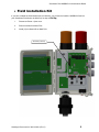
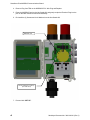
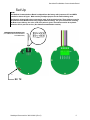
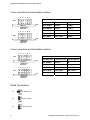
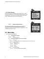
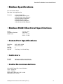
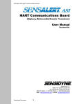
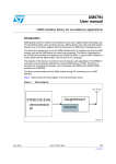
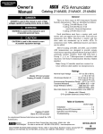
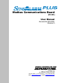
Modbus Communications Board (RS-485) User Manual Document No. 360-0129-01 (Revision C) Sensidyne, LP. 1000 112th Circle N, Suite 100 St. Petersburg, Florida 33716 USA 800-451-9444 • +1 727-530-3602 • +1 727-539-0550 [fax] web: www.sensidyne.com • e-mail: [email protected] SensAlarm Plus MODBUS Communications Board Field Installation Kit If you have ordered the field install kit p/n 821-0303-02, you will need to install the MODBUS Card into your SensAlarm Plus Monitor as follows (If not skip to Set Up): 1. Disconnect Power - Open cover. 2. Remove screws from Main PCA. 3. Install (3) Hex Stand-offs on Main PCA. Stand-Offs (3 Places) Sensidyne Document No. 360-0129-01 (Rev C) 3 SensAlarm Plus MODBUS Communications Board 4. Remove Plug from TB8 on the MODBUS PCA. Wire Plug and Replace. 5. Place the MODBUS Card on the Hex Stand-offs and gently couple the Electrical Plug into the jack on the Main Printed Circuit Board Assembly. 6. Re-install the (3) Screws and Lock-Washers into the Hex Stand-offs. MODBUS Card Screws & Washers (3 Places) (from Main PCA) 7. Proceed with “SET UP”. 4 Sensidyne Document No. 360-0129-01 (Rev C) SensAlert Plus Modbus Communication Board Set Up NOTE The Modbus Communications Board is shipped from the factory with jumpers at JP1 and HDR1 installed as shown is figure. Make certain you adjust jumpers for the network being used. The Board is shipped with wires connected to each of the terminal points. These leads are used in the final test of the Board before being shipped from the factory. For your convenience in testing the Board upon delivery, the color code of the wires is given. These wires need to be replaced before the unit is put into service. (See Cable Recommendation section) VIEWING ANGLE ORIENTATION (FOR JUMPER SETTING PROCEDURE ON FOLLOWING PAGE) HDR1 TB8 RX TX Sensidyne Document No. 360-0129-01 (Rev C) 5 SensAlert Plus Modbus Communication Board 4 wire connections and termination resistors F E D C B A (SEE VIEWING ANGLE ORIENTATION ON PREVIOUS PAGE) HDR1 PCB 4 WIRE NO TERMINATION RESISTORS F E D C B A HDR1 SensAlert Plus Test Lead Color Modbus Master TB8-5 RXD-A Brown TXD-B TB8-4 RXD-B Green TXD-A TB8-3 TXD-A Violet RXD-B TB8-2 TXD-B Gray RXD-A TB8-1 SHLD NOT USED Shield PCB 4 WIRE WITH TERMINATION RESISTORS 2 wire connections and termination resistors F E D C B A (SEE VIEWING ANGLE ORIENTATION ON PREVIOUS PAGE) HDR1 SensAlert Plus Test Lead Color Modbus Master TB8-5 RXD-A Brown B TB8-4 RXD-B Green A TB8-3 TXD-A NOT USED NOT USED TB8-2 TXD-B NOT USED NOT USED TB8-1 SHLD NOT USED Shield PCB 2 WIRE NO TERMINATION RESISTORS F E D C B A HDR1 PCB 2 WIRE WITH TERMINATION RESISTORS Shield Terminations 6 JP1 NO TERMINATION JP1 CIRCUIT GROUND JP1 CHASSIS GROUND Sensidyne Document No. 360-0129-01 (Rev C) SensAlert Plus Modbus Communication Board • Refer to SensAlarm Plus User Manual (P/N: 360-0126-01) The following section is reprinted from the SensAlarm Plus User Manual. A properly installed Modbus Communication Board will indicate Modbus Comm at step 5.2.5.5. If “Hart Comm.” Or “No Comm Installed” appears, an improper Board has been installed in the monitor. 5.2 Main Menu As shown on the example display to the right, the top level (main) menu allows the selection of several submenus, documented below. Selecting OK brings up the submenus. Main Menu > Calibration Mode Calibration Mode MaintenanceMode Mode Maintenance Data Review Data Review Test-on-Demand Test On Demand System Config > System Configuration Lost Password System Configuration 5.2.5 System Configuration The System Configuration menu provides a large number of functions for configuring the operation of the unit. These include conducting a self test, alarm and relay setup, adjusting the 4 mA & 20 mA outputs, setting the date and time, communications setup, adjusting TOD cell functions, setting combustible sensor parameters, and setting a password. Calibration Mode >> Self Test Maintenance Alarm Settings Mode 4/20 mA Adjustment Data Review Adjust Date/Time Test-on-Demand Communication Setup System TOD ModeConfig Adjustment --more-- Communication Setup > Calibration Mode 5.2.5.5 Communication Setup This menu provides adjustment for both standard and optional installed communications methods. Options installed will be displayed. Possible options are Hart Comm Modbus Comm Maintenance Mode > 4/20mA Communication Data Review Modbus Comm Test-on-Demand System Config (If no Communications Option is installed Display will read) No Comm Installed Modbus Comm > Calibration Mode Modbus Address Maintenance Mode Baud Rate Data Review Parity Test-on-Demand Stop Bits System Config Sensidyne Document No. 360-0129-01 (Rev C) 7 SensAlert Plus Modbus Communication Board 5.2.3 Data Review Data review allows the examination of data stored by the unit. Data reviews are available for the Test-On-Demand gas generating cell, the installed sensor, Fault Currents, Active Alarms/Faults, Rly Alm Fault Config., Calibration Info, and Communication Review. 5.2.3.7 Data Review Calibration > > TOD Review Mode Sensor Review Mode Maintenance Fault Currents Data Review Active Alarms/Faults Test-on-Demand Rly Alm Fault Config System Config Calibration Info Communication Review Communication Review The Communication Review screen displays the present setting Of the 4/20mA Current Loop (SensAlert sensor ID or None). Depending on which Communications Option is installed (None, HART, or Modbus) the display will vary. Communications Review > Calibration Mode Maintenance Mode 4/20mA Communications SensAlert Sensor ID Data Review Modbus Comm Test-on-Demand Add 013 Baud 38400 System Config Parity Even Stop 1 5.1 Menu Map 5.5. Communication Setup 5.5.1. 4-20ma Communications 5.5.1.1. None 5.5.1.2. SensAlert Sensor ID 5.5.2. Hart Comm or Modbus or No Comm Installed 5.5.2.1. Hart Comm 5.5.2.1.1. – No User Adjustments Through this Interface Use Current Loop 5.5.2.2. Modbus Comm 5.5.2.2.1. Modbus Address 5.5.2.2.2. Baud Rate 5.5.2.2.3. Parity 5.5.2.2.4. Stop bits 5.5.2.3. No Comm Installed 5.5.2.3.1. -No Communications Board Installed 8 Sensidyne Document No. 360-0129-01 (Rev C) SensAlert Plus Modbus Communication Board • Modbus Specifications RTU Transmission Mode Byte-order: most-significant-first Functions 01 (0x01) Read Coils 02 (0x02) Read Discrete Inputs 03 (0x03) Read Holding Registers 04 (0x04) Read Input Registers 05 (0x05) Write Single Coil 06 (0x06) Write Single Register 16 (0x10) Write Multiple Registers • Modbus RS485 Electrical Specifications RS485 Termination Resisitors RS485 Load 2 wire or 4 wire 120 Ωohms 2 wire – ½ Load 4 wire – ¼ Load • Comm Port Specifications Baud Rate Parity Start Bit Data Bits Stop Bit 9600, 19200, 38400 None, Even, Odd 1 8 1 for Parity, 1 or 2 for No Parity • Indicators RX LED TX LED Indicates received communications Indicates transmitted communications • Cable Recommendations 20-24 AWG Twisted Pair, Overall Shielded 2 wire – Single Pair 4 wire – Two Pair Belden 9501, 9502, 8451, 8761, 1419A Alpha Wire 5471C, 5472C Sensidyne Document No. 360-0129-01 (Rev C) 9 SensAlert Plus Modbus Communication Board • Modbus Register Addresses This section provides information about the implementation of the Modbus Protocol on the Sensidyne SensAlarm Plus Monitor. The following Modbus Register Addresses have been implemented in the SensAlarm Plus device. Coils 00001 00004 00007 00010 00017 00021 00022 00023 00024 00025 00026 00027 00028 00032 00041 00042 00043 00044 00045 00046 00047 00048 Start Zeroing Sensor Start Sensor Calibration Start Automatic TOD Test Stop Sensor Calibration Clear Latched Relays Enable Alarm 1 Enable Alarm 2 Enable Alarm 3 Enable Alarm 4 Relay 1 Latch Enable Relay 2 Latch Enable Relay 3 Latch Enable Relay 4 Latch Enable TOD Fail Enable Head Fail Fault Enable Sensor Missing Fault Enable Sensor Fail Fault Enable Sensor End of Life Fault Enable TOD End of Life Enable Loop Current Out of Tolerance Fault Enable Calibration Mode Fault Enable Maintenance Mode Fault Enable Discrete Inputs 10001 10002 10003 10004 10005 10006 10007 10008 10009 10017 10018 10019 10020 10031 10033 10034 10035 10036 10037 10038 10039 10040 10 Zeroing Sensor Started Zeroing Sensor Good Zeroing Sensor Failed Calibration of Sensor Started Calibration of Sensor Good Calibration of Sensor Failed TOD Test Started TOD Test Good TOD Test Failed Alarm 1 Active Alarm 2 Active Alarm 3 Active Alarm 4 Active TOD Test Fail Active Missing Sensor Active Head Fail Active Sensor Fail Active Sensor End of Life Active TOD End of Life Active Loop Current Out of Tolerance Calibration Mode Fault Active Maintenance Mode Fault Active Sensidyne Document No. 360-0129-01 (Rev C) SensAlert Plus Modbus Communication Board • Modbus Register Addresses Input Registers 30031 30033 30035 30037 30039 30041 30043 30095 30097 30099 30101 30103 30105 30111 30159 30160 30161 30162 30163 30164 30175 30177 30179 30181 30183 Float Float Float Float Float Float Float Long Float Float Long Float Long Float Int Int Int Int Int Int Float Float Float Long Int Gas Concentration Full Scale Value Loop Current TWA Gas Concentration Sensor Temperature Degrees C Max Gas Concentration Date/Time of Max Gas Concentration Date/Time of Last Calibration Last Calibration Gas Concentration Minimum Sensor Temperature Date/Time of Minimum Sensor Temperature Maximum Sensor Temperature Date/Time of Maximum Sensor Temperature Calibration Pre Exposure Gas Concentration 8 bits Sensor Type High 8 bits Sensor Type Low Display Units 8 bits Display Version High 8 bits Display Version Low 8 bits Comm Board High 8 bits Comm Board Low 8 bits Head Version High 8 bits Head Version Low 8bits Sensor Version High 8 bits Sensor Version Low Minimum Span Value Maximum Span Value Peak TOD Test Value Date/Time of Last TOD Test 12 Bit Representation of Current Loop, 4mA is a count of 800, 20mA is a count of 4000 Date/Time values are seconds from 12:00:00 AM March 1, 2000 Holding Registers 40127 40129 40131 40133 Float Float Float Float Alarm 1 Setpoint Alarm 2 Setpoint Alarm 3 Setpoint Alarm 4 Setpoint For further information about the Modbus protocol contact the Modbus-IDA at www.modbus.org Modbus-IDA Headquarters: 37 Wheeler Rd North Grafton, MA 01536 Mailing Address: PO Box 628 Hopkinton, MA 01748 Telephone: +1 508-435-7170 Fax: +1 508-435-6929 e-mail: [email protected] Sensidyne Document No. 360-0129-01 (Rev C) 11 Sensidyne, LP. 1000 112th Circle N, Suite 100 St. Petersburg, Florida 33716 USA 800-451-9444 • +1 727-530-3602 • +1 727-539-0550 [fax] web: www.sensidyne.com • e-mail: [email protected]