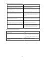
1
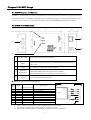
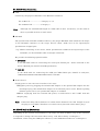
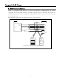
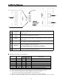
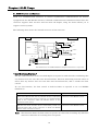
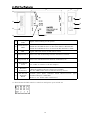
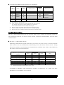
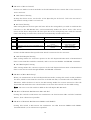
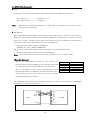
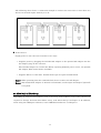
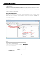
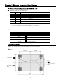
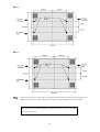
Interface Converter
Instruction Manual
LAN
RS-232C
SI-60F
LAN
RS-232C
SI-60
LAN
RS-422/485
SI-65
(13th Edition)
Introduction
Thank you for your purchase of SI series. To use it correctly, you are
advised to read and understand this instruction manual thoroughly.
Keep this together with the warranty.
Notice
Under the copyright laws, it is prohibited to reprint or duplicate any part or the whole of
this instruction manual without priority from LINEEYE CO., LTD. (“LINEEYE”)
All company and product names in this manual are trademarks or registered trademarks
of their respective companies.
The contents of this manual and specifications of the products are subject to change
without notice.
This manual has been designed and edited with great care to give you all information. If
you have any questions, feel free to direct your inquiries to LINEEYE.
LINEEYE makes no warranty or guarantee, either expressed or implied with respect to
its quality, performance, merchantability, or fitness for a particular purpose. LINEEYE
shall not be liable for direct, in-direct, special, incidental, or consequential damages
resulting from any defect in the product. The warranty and remedies set forth above are
exclusive and in lieu of all others.
Copyright © 2010 LINEEYE CO., LTD. All right reserved.
1
Safety Information
Be sure to read the following.
LINEEYE has developed and manufactured this product for purpose of using with
electrical devices such as a computer, a personal device, a measurement device,
semiconductor manufacturing equipment, a vending machine, a sequencer, display
equipment and so on. LINEEYE does not manufacture this product under the purpose of
using with equipment which may cause malfunction to do harm to the human body: control
equipment for nuclear, aircraft equipment, life maintenance equipment, traffic signals, etc.
Therefore, LINEEYE makes no guarantee with the mentioned-above use. If you use this
product for the purposes mentioned above, please contact LINEEYE considering safety like
Fail Safe under your responsibilities.
Danger Level
Warning
Caution
Should the device be used without following these symbols, there is a
possibility of accidents, such as a death or a serious injury, occurring.
Should the device be used without following these symbols, there is a
possibility of accidents, such as an injury and material damage, occurring.
* “Injury” indicates injury, burn, an electric shock, or the like which does not require hospitalization or the
extended hospital visit. “Material damage” indicates damage related to a house, a building, furniture,
apparatus, livestock or a pet.
Warning
Do not disassemble or modify the converter and AC adapter.
This may cause overheating, a fire, an electric shock, injury or unit malfunction.
Stop using the converter immediately when smoke, smells, or unusual sound
emanates from itself.
Continuous use may cause a burn, fire, or electric shock.
Keep the products dry. Keep them away from water.
Failure to do so may cause overheating, an electric shock, or unit malfunction.
Do not insert the metal scrap or the rubbish such as lead wires into the opening.
Doing so may cause overheating, an electric shock, or unit malfunction.
Never touch the converter and AC adapter with wet hands.
Doing so may cause an electric shock.
Never use the converter in the place where an inflammable gas leaks.
Doing so may cause ignition.
Do not conduct the installation or wiring work when power is applied.
Doing so may cause an electric shock or unit malfunction.
2
Do not use the damaged cables.
Doing so may cause fire by overheating.
Use the included AC adapter or ones specified by LINEEYE.
Failure to do so may cause overheating, fire, an electric shock, or injury.
Do not connect the power cord to an outlet that has an illegal number of connections.
Doing so may cause fire by overheating.
Caution
Do not install the converter in the unstable or vibrating place.
Doing so may cause unit malfunction or injury.
Do not install the converter in any temperature and humid places, or any places
which has the extreme temperature change.
Doing so may cause unit malfunction.
Do not install the converter in any places exposed to direct sunlight.
Doing so may cause a burn or unit malfunction by overheating.
Be sure not to short-circuit the pins on the connector.
Doing so may cause unit malfunction or injury.
Use the included AC adapter with the converter only.
Failure to do so may cause fire or injury by overheating.
Be sure to hold the converter when you disconnect the AC adapter from it.
Failure to do so may cause fire or an electric shock by damaging a cord.
Do not place the cord of the AC adapter near heating equipment.
Doing so may cause fire or an electric shock by melting the cord’s cover.
3
Contents
Chapter1
Before Using The Product .......................................................................................................................5
1-1. Overview..............................................................................................................................................................5
1-2. Specifications ......................................................................................................................................................5
1-3. Unpacking and Product Composition .................................................................................................................6
1-4. CD-ROM Included ...............................................................................................................................................6
1-5. Updating the XPort version (XPort-03 to XPort-04) ..........................................................................................6
Chapter2
SI-60F Usage ...........................................................................................................................................7
2-1. SI-60F Overview and Features...........................................................................................................................7
2-2. SI-60F Panel Explanation...................................................................................................................................7
2-3. SI-60F Cable Connection ....................................................................................................................................8
2-4. SI-60F Built-in XPort Setup ...............................................................................................................................8
Chapter3
SI-60 Usage..............................................................................................................................................9
3-1. SI-60 Overview and Features .............................................................................................................................9
3-2. SI-60 Panel Explanation ...................................................................................................................................10
3-3. SI-60 Cable Connection.....................................................................................................................................11
3-4. SI-60 Built-in XPort Setup ...............................................................................................................................11
Chapter4
SI-65 Usage............................................................................................................................................12
4-1. SI-65 Overview and Features ...........................................................................................................................12
4-2. SI-65 Panel Explanation ...................................................................................................................................13
4-3. SI-65 Hardware Setup ......................................................................................................................................14
4-4. SI-65 Cable Connection.....................................................................................................................................16
4-5. SI-65 Built-in XPort Setup ...............................................................................................................................17
Chapter5
XPort Setup ...........................................................................................................................................18
5-1. Built in XPort ....................................................................................................................................................18
5-2. Connection to the Networok .............................................................................................................................19
5-3. IP Address Assignment .....................................................................................................................................19
5-4. Setup Method (Serial Communication Conditions) .........................................................................................25
5-5. Setup Example ..................................................................................................................................................29
5-6. XPort IO pin, CP1 Control ................................................................................................................................32
5-7. Default Setup ....................................................................................................................................................32
5-8. Default Setup Using the Setup Record ............................................................................................................33
Chapter6
COM Port Redirector.............................................................................................................................36
6-1. Overview............................................................................................................................................................36
6-2. COM Port Redirector Ver4.x.x.x Installation Procedure .................................................................................37
6-3. SI-60F/SI-60/SI-65 Setup ..................................................................................................................................39
6-4. COM Port Redirector Ver4.x.x.x Setup ............................................................................................................39
Chapter7
Ethernet Connector Specification .........................................................................................................41
7-1. Ethernet Connector Specification (SI-60F, SI-60, SI-65).................................................................................41
7-2. Installation Method ..........................................................................................................................................41
Chapter8
Warranty and After-Sales Service ........................................................................................................43
8-1. Troubleshooting .................................................................................................................................................43
8-2. Warranty and Repair ........................................................................................................................................46
8-3. After-Sales Service ............................................................................................................................................46
4
Chapter1 Before Using Th e Product
1-1. Overview
SI-60F/SI-60/SI-65 are communication converters to convert asynchronous communications for
devices with the serial interface, which is often used in the FA field, into TCP/IP
communications on Ethernet LAN. These converters have built-in Lantronix XPort at the LAN
interface part, and enable a high- reliability communications.
To create software using socket communications enables to control devices with the serial ports
from a PC on the network. Also, installing the included COM port redirector makes you control
those devices by using the communications method for the serial.
1-2. Specifications
Interface
Serial
LAN
Synchronous Method
Baud Rate (bps)
Data Frame
Structure
Flow Control
LED Display
Surge Protection
Interface
Protocol
LED Display
Transformer
Insulation
Management
Compatible OS
*2
Power Supply
Power Consumption*3
Temperature
SI-60F
RS-232C
Dsub9 Pin (Male)
#4-40 UNC (inch screw)
SI-60
RS-232C
Dsub25 Pin (Female)
M2.6 mm Screw
SI-65
RS-422/485
5.08mm 6 pole terminal block
(Press-to-screw pitch type) *1
DTE fixed
DTE/DCE Switchable
Able to set the terminator.
Asynchronous
300/600/1200/2400/4800/9600/19200/38400/57600/115200/230400/460800 *1/921600 *1
Data (7 or 8) + Parity (Even, Odd or None) + Stop (1 or 2)
Xon/off, RTS/CTS
Xon/off, Line monitoring
SD, RD,
SD, RD, RS, CS, (6-20)
SD, SD/RD, DRIVER ACTIVE
15KV ESD
Ethernet IEEE802.3 RJ-45 connector 10BASE-T/100BASE-TX
ARP, UDP/IP, TCP/IP, ICMP, SNMP, TFTP, Telnet, DHCP, BOOTP, HTTP, AutoIP
10BASE-T, 100BASE-TX, Activity, Link, Full/Half duplex
1500V
Web manager, Telnet connection, Serial port connection
Microsoft Windows x86: XP/2003 Server/Vista/Windows7/2008 Server
x64: Vista/Windows7/2008 Server
DC5 to 25V / 250 to 50mA
DC5 to 12V / 300mA
DC5 to 12V / 300mA
Supplied from an
Supplied from an
Supplied from an
AC adapter or DC-IN.
AC adapter or
AC adapter or terminal block.
Dsub connector.
2.8VA
4.2VA
4.9VA
Operating: -10 to 50 degree.
Operating: -10 to 50 degree *4
5 to 95% RH
Storage: -20 to 80 degree.
Storage: -20 to 80 degree.
5 to 95% RH
Humidity
External Dimension
58(W) x 88(D) x 24(H)
65(W) x 95(D) x 24(H)
65(W) x 90(D) x 24 (H)
(mm)
Weight (g)
170
200
200
Accessories
AC adapter, Utility CD-ROM, Instruction manual, Warranty
*1 SI-60 cannot be used at 460.8Kbps and 921.6Kbps.
*2 If using the DeviceInstaller(v4.3.0.1)
*3 If using the attached AC adapter (AC100V).
*4 When the power supply voltage, which is supplied from the connector (SI-60) or the terminal block
(SI-65), is DC10V or higher, the operating temperature is limited up to +40 degree.
5
1-3. Unpacking and Product Composition
Make sure of the following when unpacking the product:
Converter
: 1
AC Adapter (DC6V 500mA)
: 1
Utility CD-ROM
: 1
Instruction Manual
: 1
Warranty
: 1
Please let your LINEEYE distributor or LINEEYE know if you find any damage to the product
caused by transportation, or if there are accessories lacking.
1-4. CD-ROM Included
The converter includes the following CD-ROM.
Utility CD-ROM
This CD-ROM includes the document file such as the instruction manual, the sample
program which is helpful to develop software by using the converter.
Also, it includes the following: the document file such as the XPort user’s manual, XPort
Installer, and the utility software for XPort such as COM port redirector issued by Lantronix.
To learn more detail about the contents, read README_E.TXT on the root folder of CD-ROM.
Firmware, utility software, and a user’s manual for XPort may be updated. You can
download the latest versions from website of Lantronix (http://www.lantronix.com).
1-5. Updating the XPort version (XPort-03 to XPort-04)
Updated Xport (Xport-03 to Xport-04) does not affect any specifications of SI-60/65/60F. And,
you can use SI-60/65/60F of Xport-03 and Xport-04 together without any concerns.
Differences
Differences
Product
Firmware
Web Manager
Description
Xport-03 -> Xport-04
Smoked LED lends but the specifications of LEDs are the same.
Ver 6.6.0.2 -> Ver 6.7.0.1
Correct the bug of DNS request. (If there is “-“ in the domain
name, DNS request cannot work.
LINEEYE does not
recommend using it.)
Ver 1.7.0.1 ->Ver 1.8.0.1
(Need to be changed to have the same version with Lantronix.
There is no change on the Xport.)
6
Chapter2 SI-60F Usag e
2-1. SI-60F Overview and Features
SI-60F is a converter to convert asynchronous communications for devices equipped with the
RS-232C interface to TCP/IP communications on Ethernet LAN. It connects RS-232C interface
device to a PC without a serial port via LAN, with a small DTE(fixed) Dsub9 pin (male).
2-2. SI-60F Panel Explanation
88
2
24
(1)
(4)
58
(5)
(3)
(2)
(1)
Power LED
Lights when turning on the power.
(2)
Data Status
LED
Indicates the data transmission/ reception status for RS-232C.
Lights when the pin signal corresponding to Dsub connector is
above +3V.
(3)
AC Adapter
Jack
Is a socket to connect to the AC adapter.
(4)
Ethernet
Connector
Ethernet IEEE802.3 RJ-45connector
10Base-T/100Base-TX auto-detection available.
Has a LED which shows a link and activity status.
(5)
RS-232C
Connector
Dsub9 pin (male)
Screw: #4-40 UNC(inch screw)
RS-232C Connector Pin Assignment
Pin
No.
Name
1
2
3
4
5
6
7
8
9
CD
RD
SD
ER
GND
DR
RS
CS
CI
I/O Direction
*1
DTE
In
Out
In
In
Out
In
-
LAN
RS-232C
Description
non-connected
Reception Data
Transmission Data
Internal connection to 6 pin
Signal Grand
Internal connection to 4 pin
Transmission Request
Transmission Permit
non-connected
*2
*2
XPort
Data Out
SD
Data In
RD
CP0
RS
CP1
CS
CP2
DR
*1 “Out” means a direction to output signals from the converter.
“In” means a direction to input signals to the converter.
*2 Inputs the negated signals to the CP1 terminal on a built-in XPort.
7
ER
GND
2-3. SI-60F Cable Connection
LAN
Connect by the proper UTP cable to the Ethernet connector.
For 10Base-T ------------------- Category 3, 4, 5
For 100Base-TX --------------- Category 5
Note:
Although the standardized length of a LAN cable is max. 100 meters, use the cable as
short as possible if there is much noise.
RS-232C
The specification of SI-60F is DTE. Connect by the proper RS-232C cable which fits the shape
of the RS-232C connector on the target devices. Then, make sure of the input/output
specification of signal pins.
(e.g.) When connecting to the device, which specification is DTE on the input/output of the
RS-232C, use the RS-232C cable of straight connection.
We provide the following optional cables.
SI-RS259
Is the RS-232C cable for connecting the serial port (Dsub9 pin - male) of SI-60F to the
device (Dsub25 pin, female) of DCE specification.
LE2-8C
Is the AUX cable for connecting the AUX port (Mini DIN8 pin, female) of analyzers,
(LE-8200/3500/2500/7200/3200/2200/1200) to SI-60F.
Power Source
Supply power to the converter in either of two ways.
Supplies power by plugging the included AC adapter or the optional AC adapter into the
AC adapter plug. The included AC adapter is for AC100V power source. When requiring
AC200V power source, an optional AC adapter is available.
When supplying from the external DC power, it needs DC5 to 25V (1.5W) from AC
adapter plug.
Note:
Connection Plug: Outer diameter is 5.5mm. Inner diameter is 2.1mm. Length of top of
the plug is 9.5+0.3mm. (Possible to use both center plus and center minus plug.)
2-4. SI-60F Built-in XPort Setup
Depending on the network environments or the usage, the built-in XPort setup of the converter
is required to change. To learn about XPort setup, read “XPort Setup” in Chapter 5.
In addition, when using the COM port redirector, read “COM Port Redirector” in Chapter 6.
8
Chapter3 SI-60 Usage
3-1. SI-60 Overview and Features
SI-60 is a communication converter to convert asynchronous communications for devices
equipped with the RS-232C interface to TCP/IP communications on Ethernet LAN. Since the
slide switch on the converter is designed for DTE/DCE switchable, any devices can be connected
to the RS-232C side.
The following chart shows the internal structure of the converter.
LAN
RS-232C
DTE/DCE
changeover
switch
Data Out
XPort
SD
Data In
RD
CP0
RS
CP1
CS
CP2
DR
ER
GND
<DTE side>
<DCE side>
DTE/DCE
changeover
switch
DTE/DCE
changeover
switch
Connection changes according to the state of the DTE/DCE changeover
9
3-2. SI-60 Panel Explanation
24
95
(1)
2
(2)
(5)
58
(6)
(4)
(3)
(1)
DTE/DCE
Switch
Changes the RS-232C connector specification of the converter to
DTE or DCE.
(2)
Power Supply
LED
(3)
Data Status
LED
Indicates a data transmission/ reception status for the RS-232C.
Lights when the pin signal corresponding to Dsub connector is
above +3V.
(4)
AC Adapter
Jack
Is a socket to connect to the AC adapter.
(5)
Ethernet
Connector
Ethernet IEEE802.3 RJ-45connector
10Base-T/100Base-TX auto-detection available.
Has a LED which shows a link and activity status.
(6)
RS-232C
Connector
Dsub25 pin (Female) M2.6 mm Screw
Lights when powering the converter.
RS-232C Connector Pin Assignment
Pin No. *1
Name
1
2
3
4
5
6
7
9
20
FG
SD
RD
RS
CS
DR
GND
+5V IN
ER
I/O Direction *2
DTE
DCE
Out
In
In
Out
Out
In
In
Out
In
In
In
In
Description
Frame Grand
Transmission Data
Reception Data
Transmission Request
Transmission Permit
Internal connection to 20 pin *3
Signal Grand
External power supply input *4
Internal connection to 6 pin *3
*1 Pins not mentioned in this table indicate the non-connected terminals.
*2 “Out” means a direction to output signals from the converter.
“In” means a direction to input signals to the converter.
*3 Inputs the negated signals to the CP1 terminal on a built-in XPort.
*4 Do not connect to the AC adapter when supplying the power through +5V IN (9 Pin).
10
3-3. SI-60 Cable Connection
LAN
Connect by the proper UTP category cable which matches the Ethernet connector.
For 10Base-T ------------------- Category 3, 4, 5
For 100Base-TX --------------- Category 5
Note:
Although the standardized length of a LAN cable is max. 100 meters, use the cable as
short as possible if there is much noise.
RS-232C
Connect with the proper RS-232C cable which fits the shape of the RS-232C connector on the
target devices. Then, make sure of the input/output specification of signal pins and
connection of the RS-232C cable. Set DTE/DCE switch.
(eg.) When connecting to the PC which is DTE specification using the RS-232C cable of
straight connection, set as DCE for the switch.
We provide the following optional cables.
SI-RS259
Is the RS-232C cable for connecting the serial port (Dsub9 pin, male) of the PC to SI- 60
(set DCE for switch).
LE2-8C
Is the AUX cable for connecting the AUX port (MINI DIN 8 pin, female) of analyzers,
(LE-8200/3500/2500/7200/3200/2200/1200) to SI-60 (set DTE for the switch).
Power Source
Supply power to the converter in either of two ways.
Supplies power by plugging the included AC adapter or the optional AC adapter into the
AC adapter plug.
The included AC adapter is for AC100V power source. When requiring AC200V power
source, an optional AC adapter is available.
Supply DC5V to 12V(max. 300mA) from 9pin of RS-232C connector.
Note:
Do not connect an AC adapter when supplying from RS-232C connector.
3-4. SI-60 Built-in XPort Setup
Depending on network environments or the usage, the built-in XPort setup of the converter is
required to change. To learn about XPort setup, read “XPort Setup” in Chapter 5.
In addition, when using the COM port redirector, read “COM Port Redirector” in Chapter 6.
11
Chapter4 SI-65 Usage
4-1. SI-65 Overview and Features
SI-65 is a communication converter to convert asynchronous communications for devices
equipped with the RS-422/485 interface to TCP/IP communications on Ethernet LAN. Since the
converter supports both two-wire and four-wire full duplex, using the device allows you to
support various systems.
The following chart shows the internal structure of the converter.
RS-422/485
LAN
SD+
Data Out
100Ω
Data In
XPort
CP0
SW-B3
SD-
NC
CP1
SW-B1
SD/RD+
100Ω
CP2
SW-B2
SW-B4
SD/RD-
SW-A1..4
GND
Line monitor circuit
Driver control circuit
RS-422/485 driver IC: MAX3088(Maxim Integrated Products) or equivalent
< Line Monitoring Function >
RS-485 communications of two-wire half duplex is required to send data after confirming that
any devices have not sent data into the RS-485 line. The line monitoring function allows to
detect that any devices have not sent data into the RS-485 line, and to conduct the flow
control.
To use this function, the flow control of built-in XPort is required to set to CTS/RTS
(Hardware).
RS-485 Line Condition
The period of time from when to detect a space bit of the
data in the RS-485 line sent by another device, to when not
to get to continuously detect a space bit over internal timer
time of the converter, while the RS-485 driver of the
converter is not active.
The period of time when not to detect a space bit in the
RS-485 line which another device continuously sends over
internal timer time of the converter, or when the RS-485
driver of the converter is active.
Note:
Flow Control Condition
Prohibits sending data from the
converter to the RS-485 circuit.
Permits to send data from the
converter to the RS-485 circuit.
This function allows the flow control to operate in a direction of sending only. The flow
control in a direction of receiving does not operate.
12
4-2. SI-65 Panel Explanation
90
24
2
(2)
(7)
58
(8)
(4)
(6)
(5)
(1)
(3)
(1)
Power Supply
LED
(2)
Data Status
LED
(3)
Driver Status
LED
Lights when the driver for RS-485 is active.
(4)
Dip Switch A
Selects the line monitoring function and driver control.
(5)
Dip Switch B
Selects the communication method, terminator, etc.
(6)
AC Adapter
Jack
(7)
Ethernet
Connector
(8)
RS-422/485
Terminal
Block
Lights when turning on the power.
Indicates a data transmission/ reception status for RS-422/485.
Blinks the SD LED if there is data from LAN to RS-422/485.
Blinks the RD LED if there is data from RS-422/485 to LAN.
Is a socket to connect to the AC adapter.
Ethernet IEEE802.3 RJ-45 connector.
10Base-T/100Base-TX auto-detection available.
Has the LEDs which show a link and activity status.
5.08mm pitch
6pole
terminal block (Press-to-screw
Standard Torque: 0.5Nm/M3.
(Refer to “4-4. SI-65 cable connection”)
*1: Press down the DIP switch to switch on and press up to switch off.
13
type)
6 Pole Terminal Block Pin Assignment for RS-422/485
Full Duplex Mode *1
I/O
Direction
Description
*2
Out
Transmission Data +
Out
Transmission Data –
Reception Data +
In
Terminal
No.
Name
1
2
SD+
SD-
3
SD/RD+
4
SD/RD-
In
5
GND
-
6
+5V IN
-
*1
*2
Reception Data –
Half Duplex Mode *1
I/O
Direction
Description
*2
Cannot use *3
Cannot use *3
Transmission/Rece
I/O
ption Data +
Transmission/Rece
I/O
ption Data -
Signal Grand *4
External Power
Input *5
Can switch by the dip switch.
“Out” means a direction to output signals from the converter.
“In” means a direction to input signals to the converter.
“I/O” means both directions to input and output.
Do not connect anything when using the half duplex mode.
Connect GND to prevent devices from over voltage damage.
Do not plug the AC adapter when powering from +5V IN (No.6).
*3
*4
*5
4-3. SI-65 Hardware Setup
The two 4-position dip switches on the converter allows you to conduct the following setups: the
line monitoring function, the driver control method, terminator enable/disable, and echo back
enable/disable.
SW-A No. 1-3 (Baud Rate Setup)
Following communication speed (baud rate) you wish to use, this setup is to set the internal
timer used for the non-communication monitoring circuit and driver control circuit.
Using
this timer conducts to monitoring non-communication condition more than 16 bits in RS-485
line and to control the RS-485 driver.
Speed (bps)
[ ] indicates a representative
example.
Over 300 [300, 600]
Over 1200 [1200]
Over 2400 [2400]
Over 4800 [4800]
Over 9600 [9600]
Over 19200 [19200]
Over 38400 [38400, 57600]
Over 115.2k [115.2k, 230.4k]
*1
SW-A
No.1
No.2
No.3
Internal Timer *1
(ms)
OFF
ON
OFF
ON
OFF
ON
OFF
ON
OFF
OFF
ON
ON
OFF
OFF
ON
ON
OFF
OFF
OFF
OFF
ON
ON
ON
ON
57
14.3
7.1
3.6
1.8
0.9
0.45
0.11
The internal timer is accurate at +10 to -10%.
At 460kbps or 920kbps, CPU performance of XPort is required to set to high. For more
information, see the XPort user’s manual.
SW-A
No.4
Meaning
RS-422/485 transmission driver control
14
OFF
Active
ON
Auto
SW-A No.4 (Driver Control)
Selects two kinds of control methods in the RS-422/485 driver control line of the converter:
active and auto.
OFF (Active) Setting
To keep the driver active, set the CP1 of the Xport IO pin “L”(active). (“H” is for non-active.)
The default setting of CP1 is a low level.
ON (Auto) Setting
This setting detects the first space bit (start bit) in the string which you wish to send from the
converter to the RS-422/485 line, and automatically makes the driver active. The active
status of the driver keeps from the last space bit in the string being sent until the internal
timer time being set. After that, the driver automatically becomes non-active.
SW-B
No.1
No.2
No.3
Meaning
Select a line mode
Echo reception of transmission data
Terminal control between SD+ and SD-.
No.4
Terminal control between SD/RD+ and
SD/RD-.
OFF
RS-422 (full duplex)
With echo back
Without terminal
control
Without terminal
control
ON
RS-485(half duplex)
Without echo back
With terminal
control(100 ohm)
With terminal
control(100 ohm)
SW-B No1 (Line Mode)
Selects the RS-422/485 line specification which is connected to the converter.
OFF (Full Duplex) Setting
This setting makes the converter operate in the full duplex RS-422 mode. Communicated
data is sent from SD+ and SD- terminals, and is received to SD/RD+ and SD/RD- terminals.
ON (Half Duplex) Setting
This setting makes the converter operate in the half duplex RS-485 mode. Communicated
data is sent and received through SD/RD+ and SD/RD- terminals.
SW-B No.2 (Echo Back Setup)
When you communicate in the half duplex RS-485 mode, setting this switch to ON prohibits
the data, which is sent from the converter to the RS-485 line, is echoed back to the LAN host.
Therefore, while the driver is active, the ON setting makes the receiver non-active. The full
duplex RS-422 mode does not echo back data even when this switch is in the OFF setting.
Note:
Be sure to set this switch to OFF in the full duplex RS-422 mode.
SW-B No.3 (Terminal End Between SD+ and SD-)
Setting this switch to ON inserts the terminator 100 ohm between SD+ and SD- (terminal
block 1, 2) in a direction of parallel.
SW-B No.4 (Terminal End Between SD/RD+ and SD/RD-)
Setting this switch to ON inserts the terminator 100 ohm between SD/RD+ and SD/RD(terminal block 3, 4) in a direction of parallel.
15
4-4. SI-65 Cable Connection
LAN
Connect by the proper UTP category cable which matches the Ethernet connector.
For 10Base-T ------------------- Category 3, 4, 5
For 100Base-TX --------------- Category 5
Note:
Although the standardized length of a LAN cable is a maximum 100 meter, use the
cable as short as possible.
RS-422/485
After confirming the RS-422/485 specification of the target device, connect to the device by
using the cable of which conductor size should be AWG24-14, single wire 0.2- 2.5mm2, twisted
cable 0.12- 1.5mm2, L=6mm can be removed. If using the ferrule terminal, ferrule diameter
should be 1.5mm or less. Following are the recommendation.
Phoenix Contact Inc. “AI0.25-8YE AWG24”
JST Mfg. Co., Ltd.” TUB-05 AWG26-22”
There is not a specific RS-422/485 cable. Following is the recommended cable.
UL2464 signal cable shield twisted pair AWG24-22.
Note:
To prevent the devices from over voltage damage, be sure to connect GND.
<Transfer Distance>
The faster communication speed is, the shorter the
transfer distance for RS-422/485 is. See the right table and
set communication speed following the actual distance.
Also, the maximum of the actual communication speed
changes depending on conditions: environments like noise,
Distance (m)
100
200
600
1200
2400
Speed (bps)
Over 920k
Over 230.4k
Over 115.2k
Over 57.6k
Over 9,600
cable features used, etc. For actual use, be sure to conduct
a communication test to check.
The following chart shows the connection example to connect the converter to LINEEYE
SI-20FA in the full duplex mode by 1 to 1.
SD+
SD-
SD+
SD-
SD/RD+
SD/RD -
RD+
RDOT+
OT-
SI-65
IN
INGND
GND
16
SI- 20FA
The following chart shows a connection example to connect the converter to more than two
devices in the half duplex mode by N to N.
Power Source
Supply power to the converter in either of two ways.
• Supplies power by plugging the included AC adapter or the optional AC adapter into the
AC adapter plug on the converter.
The included adapter is for AC100V. When requiring AC200V power source, an optional
AC adapter, DSA-0151F-09A is available.
• Supplies DC+5 to +12V (max. 300mA) from 6 pin of 6 pole terminal block.
Note1: When powering from the terminal block, do not connect the AC adapter.
Note2: The included AC adapter is AC100V. For AC200V, a wide input AC adapter (optional)
is required.
4-5. SI-65 Built-in XPort Setup
Depending on network environments used or the usage, built-in XPort setup of the converter is
required to change. To learn about XPort setup, read “XPort Setup” in Chapter 5. In addition,
when using the COM port redirector, read “COM Port Redirector” in Chapter 6.
17
Chapter5 XPort Setup
5-1. Built in XPort
LINEEYE has sold SI-60F/SI-60/SI-65 with XPort-03 or Xport-04 with v1.8 and v6.x (v6.1.0.0 or
former). You should have Xport-04 with v6.7.0.1 if you have this instruction manual.
*There is no difference between Xport-03 and Xport-04 on specifications. DeviceInstaller
(v4.3.0.1) displays as “Xport-03/04”.
How to find the XPort version:
Open the DeviceInstaller(v4.3.0.1) and find “XPort-03/04-firmware v6.x.x.x” or see the “Device
Details”. You can also check the massage “Software version V6.x.x.x(xxxxxx) XPTEXE” when
connecting to the Telnet.
DeviceInstaller
Telnet
MAC address XXXXXXXXXXXX
Software version V6.7.0.1(100420) XPTEXE
Press Enter for Setup Mode
18
5-2. Connection to the Networok
To set the products from the PC via LAN cable, use the cross cable for directly connecting to the
PC. And, use the straight cable when using the HUB (etc.) to connect to the PC.
SI-60F/SI-60/SI-65
SI-60F/SI-60/SI-65
LAN cross cable
PC
LAN straight cable
HUB
LAN straight cable
PC
5-3. IP Address Assignment
Before using the converter, you need to assign IP address to the built-in XPort.
There are some IP address assignment methods. Assign by the proper method, concerning the
usage and environments, and consulting with your network manager.
Auto IP address Assignment by using DHCP and Auto IP function
Set the IP address of Xport as following to use DHCP and Auto IP function.
IP address
0.0.0.0
0.0.1.0
(factory setting)
DHCP
Valid
Valid
Auto IP
Valid
Invalid
Using the DHCP Function
When the DHCP function is valid, XPort receives IP address, subnet mask and default
gateway address, which were dynamically assigned by DHCP server on the network, at the
time of starting XPort operation.
Using the AutoIP Function
When AutoIP function is valid and there is no DHCP server on the network, XPort selects an
IP address within the class B subnet 169.254.x.x, at the time of starting Xport operation. And
it uses the ARP request to check whether or not any devices on the network use the address.
If it is not used, the address will be used as the XPort address. If it is used, XPort selects
another IP address from the reserved addresses, and check it again by the ARP request.
AutoIP is for small-scale network without DHCP server to assign the IP address. AutoIP
cannot be used as DHCP. When the DHCP server is found, XPort will restart after switching
to IP address assigned by the DHCP server. Setting the IP address to 0.0.1.0 keeps the DHCP
function valid, and only makes the AutoIP function invalid.
When setting IP address, you may need the hardware address of the converter. The
hardware address, which may also be called Ethernet or MAC address, is the original
address assigned to network devices. The address is written on the bottom of LAN
connector on the converter. Before starting the setup, check the address.
19
Using the Device Installer
The CD-ROM contains a utility “Device Installer” to assign the IP address. “Microsoft .NET
Framework 2.0” or “.NET Framework 4.0” are needed for some version of the Device Installer.
Device Installer
.NET
OS
Folder
2000/2003 Server/XP/
Ver4.2.0.1
Vista(32bit)
(Di32DL_4.2.0.1_Web.exe)
X86: XP/2003 Server/Vista
Ver4.3.0.1
Framework
Ver4.2.0.1
Ver4.3.0.1
Ver2.0
Ver4.0
Windows7/2008 Server
(setup.exe)
X64: Vista/Window7/2008 Server
If you already have DeviceInstaller(v4.2.0.1) on Windows XP or Vista, you do not have to
update to the DeviceInstaller(v4.3.0.1).
Note: Please use DeviceInstaller (v3.6.0.6) when using Xport firmware v6.x and v1.8 (or
former) together. When using DeviceInstaller (v3.6.0.6), v6.x of XPort-03/04 is displayed
as “Unknown:x5”. Open the DeviceInstaller and connect from the web manager or telnet
to setup XPort v6.x. You can install the Device Installer (v3.6.0.6) from CD-ROM, which
was attached to the product.
Installing the Device Installer
If you already have different version of DeviceInstaller, please uninstall it.
Note: Please start installing where the Internet is available. “.NET Framwork” will be
automatically installed when starting the installation.
1. Insert the utility CD-ROM into the CD-ROM drive.
2. Select “Run…” from the start menu.
For the DeviceInstaller V4.3.0.1, enter as following:
“CD-ROM Drivename:\lantronix\DeviceInstaller\Ver4.3.0.1\setup.exe”.
3. Follow the installation wizard instructions.
After Installing the DeviceInstaller, following page will be appeared, and select “No”.
Only when PIB file (File for corresponding the Device ID and Device name) needs to be
updated, select “Yes”.
20
Selecting the Device on Device Installer
1. Start Device Installer from the start menu. The main window of Device Installer
appears. It finds SI-60F/SI-60/SI-65 connected to the network automatically and
lists in a table on the main window. (If there are devices other than
SI-60F/SI-60/SI-65 using XPort on the network, they are also listed in a table..)
2.
Select what matches the hardware address for the device being set from the table.
Fixed IP Assignment Method on Device Installer
1. Select the device you would like to setup and click “Assign IP” (or from “Device”
menu, select “Assign IP Address”). “Assign IP Address” dialog box appears. Select
“Assign a specific IP address” and click “Next” button.
If the IP address is not selected from the listed table on Device Installer, “Device
Identification” page will be displayed. Enter the hardware address of the device
being set and click “Next” button to display “Assign IP Address” dialog box. (You can
find the hardware address at the lower part of LAN connector.)
21
2. “IP Settings” page appears. Enter the values for IP address, Subnet mask and
Default gateway. Then click “Next” button.
(Input the IP address of router in the “Default gateway” when using Internet .)
3. XPort restarts by pressing “Assign” button on “Assignment” page. Then, the
specified IP address will be reflected to the screen.
DHCP/Auto IP Setup Method on Device Installer
1. Select a device you would like to setup, then click “Assign IP” icon or select “Assign
IP Address” from “Device” menu. “Assignment Method” dialog box appears.
2. Select “Obtain an IP Address Automatically”, and then click “Next” button.
3. “IP Discovery Settings” page appears. Select a function you would like to enable, and
then click “Next” button.
4. XPort restart by pressing “Assign” button on the “Assignment” page.
Note: We recommend you to disable DHCP and BOOTP or always keep Auto-IP
effective because when failing in the address assignment, Device Installer
cannot detect SI-60F/SI-60/SI-65 even if DHCP, BOOTP or both are
effective.
The screen and steps will be different in each version of DeviceInstaller. For more details
of DeviceInstaller, refer to the online help or XPort user’s manual in the CD-ROM.
22
Using ARP and Telnet
Set the initial setting using the hardware address.
Preparation: To use the products by Windows Vista/7, select “Telnet client” at “Turn Windows
features on or off ” from the control panel. To set the command prompt, right click on
“command prompt” from start menu and mark on “Run as administrator”.
Example of command prompt (DOS prompt) by Windows:
1. To make an ARP table entry, enter the following command.
arp -s xxx.xxx.xxx.xxx yy-yy-yy-yy-yy-yy
(xxx.xxx.xxx.xxx
:IP address you wish to set)
(yy-yy-yy-yy-yy-yy :Hardware address of the device you wish to set)
Note:
If above command is not working, try to conduct a ping for another device
operating on the network, and then enter the command again.
2. To connect the Telnet to port 1, enter the following command.
Although this connection will be failed, it temporarily changes the XPort IP address to the
address you wish to set.
telnet xxx.xxx.xxx.xxx 1
(xxx.xxx.xxx.xxx
Note:
:IP address you assigned by the arp command)
The IP address set by this operation is the temporary address. If you do not follow
the step 3, the IP address will be returned to the previous address after turning
off the power.
3. To connect the Telnet to port 9999, enter the following command. The connection will be
succeed this time. Press [Enter] key within 5 seconds after displaying “Press Enter for
Setup Mode”.
telnet xxx.xxx.xxx.xxx 9999
(xxx.xxx.xxx.xxx
:IP address assigned by the arp command)
MAC address XXXXXXXXXXXX
Software version XX.X (XXXXXX) XPTEXE
Press Enter for Setup Mode
23
4. The setup mode shows the present setup status, and then following menu appears.
Change Setup:
0 Server
1 Channel 1
3 E-mail
5 Expert
6 Security
7 Defaults
8 Exit without save
9 Save and exit
Your choice ?
5. Select “0 Server” from the menu to set an IP address and subnet mask. If needed, set a
gateway address too.
<Example>: The underlined parts indicate the positions to enter.
IP Address : (000) 192. (000) 168. (000) 0. (000) 68
Set Gateway IP Address (N) N
To set the gateway address, enter “Y”
Netmask: Number of Bits for Host Part (0=default) (0) 0
Set DNS Server IP addr (N) N
Change telnet config password (N) N
Change DHCP device name (not set) (N) N
When Netmask is “0”, you can use the standard
subnet mask, which corresponds the class (A, B,
C) of IP address. When Netmask is other than
“0”, specify the subnet mask by the number of
bits at the host part. (Refer to the right table.)
Subnet Mask
255.255.255.248
255.255.255.240
255.255.255.0
255.255.0.0
255.0.0.0
Netmask Value
3
4
8
16
24
6. When the menu appears again, select “9 Save and Exit.” Then, XPort will restart after
saving the setup.
Change Setup:
0 Server
1 Channel 1
3 E-mail
5 Expert
6 Security
7 Default
8 Exit without save
9 Save and exit
Parameters stored ...
Your choice ?
Using the Serial Port Connection (SI-60F/SI-60 Only)
SI-60F/SI-60 allows you to send the special command from the RS-232C port using the setup
mode, and set the IP address described in step 4 (above). Refer to the “5-4 Setup Method” ->
“Setup Mode Usage” for more information about setup mode.
24
5-4. Setup Method (Serial Communication Conditions)
There are the following methods to change the setting of serial communication of XPort.
Web Manager Usage
1. Start DeviceInstaller from the start menu to display DeviceInstaller window.
Select the device being set. Select “Web Configuration” tab and click “
” icon.
Enter the user name and the password, as you will be required.
If you have not set your user name and password, enter nothing and click “OK”.
Note:
You cannot change all of the setup items for XPort by Web manager. To change the
items you cannot change by Web manager, use Telnet or Setup Mode. Setting items
and screen will be different in each version of Web manager.
2. Change the values, which you have to change on the display of the settings state.
<Example: Changing the serial port>
1) Select “Serial Settings”.
2) Set “Protocol” to be “RS-232C”. (Set “RS-232C” for SI-65 also.)
3) After setting the various settings of serial port in the “Port Settings”, click “OK”
button. (“Done!” will be displayed.)
3. “Done!” appears. After it disappears, click “Apply Settings” to make XPort save the
settings and restart.
Note: When using SI-60F/SI-65 with baud rate 460800/921600bps of the serial port, select
“Server” and set High to “CPU Performance Mode”. Then, set baud rate of “Serial
Settings”. For more details about setting items and methods, refer to on-line help or
user’s manual of XPort.
25
Setup Mode Usage
Connecting the Telnet or the serial port (SI-60F/SI-60 only) allows you to conduct the setup
by accessing to built-in XPort.
Note:
SI-65 cannot be connected to RS-232C serial port directly.
LINEEYE does not
recommend setting SI-65 via serial port.
The Telnet and serial port connection has the different procedures to enter the setup mode.
The following shows each procedure for those connections.
Telnet Connection Procedure
1.
Start the “DeviceInstaller”.
2.
Select the target device. Select [Telnet setting] tab and then click [Connection] icon.
(It is possible to input the IP address and Port number directly.)
3.
When the connection is successful, the following message appears. To enter the setup
mode, press the Enter key within 5 seconds. If more than 5 seconds pass without
pressing, Telnet connection will be cut.
MAC address XXXXXXXXXXXX
Software version XX.X (XXXXXX) XPTEXE
Press Enter for Setup Mode
Serial Port Connection Procedure
1.
Connect the RS-232C port of SI-60F/SI-60 to the serial port on a PC by the RS-232C
cable. Use a cross cable for SI-60F. When using SI-60, confirm the cable specification
and conduct the setup for the DTE-DCE change-over switch.
2.
Start the communication software on a PC, and set communication conditions to the
following values.
Communication speed --------------- 9600 bps
Data Bit --------------------------------- 8 bit
Parity ------------------------------------ none
Stop Bit --------------------------------- 1 bit
Flow Control --------------------------- none
3.
To enter the setup mode, send more than 3 characters of “x” from a PC within 1
second after powering the converter. If the converter fails to receive them within a
time limit, XPort normally starts operating. To certainly conduct this procedure,
power the converter pressing the “x” key on the keyboard of the PC.
26
4.
When the procedure is successful, the following message appears. To enter the setup
mode, press the Enter key within 5 seconds. If more than 5 seconds pass without
pressing, XPort will start the normal operation.
MAC address XXXXXXXXXXXX
Software version XX.X (XXXXXX) XPTEXE
Press Enter for Setup Mode
When you enter the setup mode by the Telnet or serial port connection, the present setup
status is displayed, then the following menu appears.
Change Setup:
0 Server
1 Channel 1
3 E-mail
5 Expert
6 Security
7 Defaults
8 Exit without save
9 Save and exit
Your choice ?
Set the necessary settings in the “1 Channel 1”.(e.g.; server mode, serial port etc.)
Baudrate (9600) ?
Select the serial speed from 300, 600, 1200, 2400, 4800,
9600, 19200, 38400, 57600, 115200, 230400, 460800,
921600. Set “High Performance Mode” to be “Y” if the
speed is more than 460800.
Set the serial interface mode in BIT unit and input in
I/F Mode (4C) ?
HEX.
I/F Mode
7 6
RS-232C
7bit
8bit
No Parity
Even Parity
Odd Parity
1stop bit
0 1
2stop bit
1 1
5 4 3 2 1 0
0 0
1 0
1 1
0 0
1 1
0 1
Set the serial flow control in HEX.
Flow (00) ?
Port No (10001) ?
Flow
Hex
No flow contorol
Software Flow(Xon/Xoff)
Hardware Flow(RTS/CTS)
Software Flow(Xon/Xoff transmit to LAN)
00
01
02
05
Set the received port number.
27
ConnectMode (C0) ?
Input the connect mode in Hex.
Connect Mode
HEX
Do not allow connection
Allow connection
Allow connection in DTR mode
Do not connect automatically
Connect automatically when receiving data from serial
Connect automatically as DTR mode of serial
Connect by hand when inputting commands from serial
Connect automatically
00
C0
40
00
01
02
04
05
Send '+++' in Modem Mode
Show IP addr after 'RING'
Auto increment source port
(Y) ?
(Y) ?
(N) ?
Remote IP Address : (000) .(000) .(000) .(000)
Remote Port
(0) ?
DisConnMode (00) ?
FlushMode
(00) ?
DisConnTime (00:00) ?:
SendChar 1
(00) ?
SendChar 2
(00)?
If you do not need to change any settings, just press “Enter”.
Select an item you wish to change, and conduct the setup following instructions. After that,
select “9 Save and exit” from the menu to reflect the changed value to XPort. To learn more
about settings, refer to the on-line help or XPort user’s manual of Lantronix, ltd.
Note: To use SI-60F/65 for serial port at baud rate: 460800/921600bps, select “5 Expert” at
menu. And, change “CPU Performance Mode” to “2=High” at “CPU performance (0=Regular,
1=Low, 2=Hight: (0)?”. And then set the baud rate.
■Use “SILANIOinit”
“SILANIOinit” is useful to set more than one IP address and each setting (setup files) on the
Xport. “SILANIOinit” is recorded in the attached CD-ROM as “\LINEEYE\SILANIOinit”
folder. To use this application, refer to the “SILANIOinit.txt”.
*Since an installer is not attached, copy the “exe” file. To uninstall the application, delete the
“exe” file.
*To change the configurations other than IP address, use the Web Manager or setup mode at
Telnet connection.
*LINEEYE has no liability if you use other version of Xport, or you downgrade the firmware.
*This application is for LINEEYE products (SI and LANIO series only).
28
5-5. Setup Example
The following shows the setup examples for the normal operation.
Set the IP address, local port, mode and communication conditions of serial port.
To learn about the description of each setup, read the XPort user’s manual. In addition, the
item names and setting values are indicated based on the case of using the web manager.
SI-60F/SI-60/SI-65 basic setting
IP address
Set the IP address, subnet mask, default gateway. (Refer to “4-1. IP Address
Assignment) Receive IP address automatically if you cannot have any IP address
from DHPC server.
Serial Settings
Set “Protocol” to be “RS-232C” in serial side. Set Baud Rate, Data Bits, Parity, Stop
Bits and Flow Control to be same as the target device.
Local Port (Default; 10001)
Change the local port. Do not assign following port number as local port.
1 – 1024: well-known port
9999: setup menu
14000 – 14009: For redirectors (previously used)
30704: For remote controls of IO unit
30718: For searching DeviceInstaller
Active Connect (Default: None)
Change the client action if necessary. If set other than “None”, you need to set Remote
Host (IP address) and Remote port (Port No.) for target device.
Local Port (Default: 10001)
Change the local port if necessary. Set available local port No. (not reserved)
29
Server
When the converter is used as the target device, set the following items.
Item
Serial Port Settings
Baud Rate
Data Bits
Parity
Stop Bits
Flow Control
Connection
Accept Incoming
Active Connect
Endpoint Configuration
Local Port
Setting Value
Communication speed for the serial port
The number of data bits for the serial port
Parity bit for the serial port
The number of stop bits for the serial port
Flow control method for the serial port
Sets “Yes” (passive connection (server))
Sets “None” (no active connection (client))
Port number
Client
The following shows the setup example of when the converter is used as the device which
connects to other devices. This example shows when the converter receives the user-defined
data from the serial port, it tries to connect to the others.
Item
Serial Settings
Baud Rate
Data Bits
Parity
Stop Bits
Flow Control
Connection
Accept Incoming
Active Connect
Endpoint Configuration
Local Port
Remote Host
Remote Port
Setting Value
Communication speed for the serial port
The number of data bits for the serial port
Parity bit for the serial port
The number of stop bits for the serial port
Flow control method for the serial port
Sets “No” (no passive connection (server))
Sets “With Any Character” (active connection (client))
Port number
Sets IP address for target device when client mode.
Sets port number for target device when client mode.
If you set “Yes” for “Accept Incoming” and “With Any Character“ for “Active Connect”, you can
have server and client mode (need to set “Remoter Host” and “Remote Port”.)
Active Connect
None
With Any Character
With Active Mdm Ctrl In
With Start Character
Manual Connection
Auto Start
No auto connection
Auto connection when receiving the data from serial
Auto connection as DTR of serial
Auto connection when receiving specified 1Byte code from serial
Manual connection
Always auto connection
30
Extend serial communication by LAN
Connect two sets of SI-60F/SI-60/SI-65 using LAN, and set them as server mode or client
mode. When having some kind of data input from A or B of serial port, SI-60F/SI-60/SI-65 will
output it from the other side of serial port via LAN.
Device
A
serial
SI-60F/SI-60
SI-60F/SI-60
/SI-65 I
/SI-65 II
Setting of <SI-60F/SI-60/SI-65 I>
LAN
serial
Device
B
Setting of <SI-60F/SI-60/SI-65 II>
IP address
:192.168.0.2
IP address
:192.168.0.3
Local Port
:10001
Local Port
:10001
Accept Incoming :Yes
Accept Incoming :Yes
Active Connect :With Any Character
Active Connect : With Any Character
Remote Host
:192.168.0.3
Remote Host
:192.168.0.2
:10001
Remote Port
:10001
Remote Port
Note: You cannot check the control lines information of Device A(orB) to Device B(orA). Use the
software flow control if necessary.
UDP/IP Communication
Basically, data transmission/reception is made by TCP/IP(default). Also UDP/IP can
transmit/receive data. From Web manager, go to “Connection” and set “Protocol” to be “UDP”.
Note: Once you set “Protocol” to be “UDP”, you cannot communicate by TCP. Otherwise
change the setup.
Set “Datagram Type” to be “01”, and set “Remote Host”, “Remote Port” and so on.
31
5-6. XPort IO pin, CP1 Control
XPort CP1 pin of SI-60F/60 is for the input pin between DR and ER lines of RS-232C. And,
Xport CP1 pin of SI-65 is for the output pin of RS-422/485 driver control. To read the input
status, send TCP/IP or UDP/IP command to the port number 30704.
■CPI check command of SI-60F/60
”xxh” in the second byte of response shows the input status.
Command : 13h 00h 00h 00h 00h 00h 00h 00h 00h 00h (9byte)
Response
: 13h xxh 00h 00h 00h (5byte)
* “xxh” bit 0(LSB)=CP0 statsu, bit 1=CP1 status, bit2=CP2 status
* bit value 1=L level, bit value 0=H level (L=+3V on DR and ER of RS-232C)
■CPI control command of SI-65
“xxh” in the sixth byte of command specifies the output status. ”xxh” in the second byte of
response shows the result.
Command
: 1Bh 02h 00h 00h 00h xxh 00h 00h 00h 00h (9byte)
Response
: 1Bh xxh 00h 00h 00h (5byte)
* “xxh” bit 0(LSB)=CP0, bit1=CP1, bit2=CP2
* bit value 1=H level, bit value 0=L level (L= active on RS-422/485 driver)
* CP1 is set as “L” level as factory setting.
Note: Please do not change the Xport setting (“Active Level” etc.)
5-7. Default Setup
When a converter is shipped, the OEM Configurable Pins on built-in XPort are set as follows:
Do not change those settings.
Items
CP0
CP1
CP2
Active Level
SI-60F
HW Flow Control out
(CTS)
General Purpose I/O
(Input)
HW Flow Control In
(RTS)
Low
Setting Values
SI-60
HW Flow Control out
(CTS)
General Purpose I/O
(Input)
HW Flow Control In
(RTS)
Low
SI-65
HW Flow Control out
(CTS)
General Purpose I/O
(Output)
HW Flow Control In
(RTS)
High
Webmanager for XPort firmware v1.8 displays “CP1” for “CP0”, “CP2” for “CP1” and “CP3” for
“CP2”.
Items excepting OEM Configurable Pins have the same setups with the factory default for
XPort.
32
The following shows the main factory default values, which are common for SI-60F/SI-60/SI-65.
To learn about the factory default values not mentioned below, read the XPort user’s manual.
Items
Settings
Network: IP Configuration
IP Address
0.0.0.0
Server: Server Configuration
Telnet password
Serial Settings: Port Settings
Protocol
RS232
Baud Rate
9600
Data Bits
8
Parity
None
Stop Bits
1
Flow Control
None
Connection: Connect Mode: Passive Connection
Accept Incoming
Yes
Active Connect
None
Connection: Endpoint Configuration
Remote Host
0.0.0.0
Remote Port
0
Local Port
10001
Remarks
Enables DHCP and AutoIP
No password
Do not change
Always connected
Do not connect
No settings
No settings
Do not apply “Apply Defaults” on Webmanager and “7 Defaults” on Telnet. If you apply these,
XPort setting will be back to default value and cannot communicate as SI-60F/SI-60/SI-65.
5-8. Default Setup Using the Setup Record
It is possible to have the XPort default value (factory setting) using DeviceInstaller Ver4.x.x.x,
if you have the firmware version Ver6.x.
Note: LINEEYE do not guarantee the other versions of DeviceInstaller or firmwares.
<step>
1. In the DeviceInstaller Ver4.x.x.x, select the XPort IP address to make it to the default
value.
2. Click upgrade icon or go to [Device]
[Upgrade]
33
3.
[Device upgrade wizard –step 1/5] will appear. Select [custom install] and click [next].
4. [Device upgrade wizard –step 2/5] will appear. Click [next].
5.
[Device upgrade wizard –step 3/5] will appear. Select [Install setup records from a file] and
click [Browse].
6. Open the file [SI_60_V6701_xxxx.rec](SI-60 Ver6.7.0.1) in the folder of
“\LINEEYE\SetupRecord” in the CD. Click [next]. Select the appropriate file.
Ver6.7.0.1
SI-60
SI_60_V6701_xxxxxx.rec
SI-65
SI_65_V6701_xxxxxx.rec
34
SI-60F
SI_60F_V6701_xxxxxx.rec
7. [Device upgrade wizard –step 4/5] will appear. Click [next].
8. [Device upgrade wizard –step 5/5] will appear. “installation has finished” will be displayed.
Close the window.
It is possible that IP address may be changed for some version of DeviceInstaller.
Check the IP address.
35
Chapter6 COM Port Red ire ctor
6-1. Overview
The included CD-ROM contains Lantronix “COM Port Redirector.”
The COM Port Redirector is the utility software to get the serial communication application not
supporting the network connection to be able to use on the network.
The redirector creates the virtual COM ports in Windows. Communications for these virtual
COM ports are transferred to the serial port on the converter through the network.
Most applications using a COM port operate without troubles because a virtual COM port
seems like a real serial port; however, some applications with time limit for data
transmission/reception may not operate. This is why a waiting time of communications via
network becomes longer than one of communications for the real COM port. In this case, you
need to increment a value of a time out using application software, to support socket
communications, etc.
Note:
The COM Port Redirector works at most of the application software. However, some
applications, which have a limit to receive/transmit data, may not work well. In this
case, change the timeout of communication longer or change the setting to support
socket communications.
Note:
The COM Port Redirector cannot be used with other software, which creates the
virtual COM port. Be sure not to install the COM Port Redirector to PCs, which have
already installed such software.
Each firmware version of COM Port Redirector can be found in the CD-ROM. For COM Port
Redirector Ver4.x or later, you need to have an appropriate Microsoft .NET Framework. Please
install the .NET Framework before installing it, or be sure the Internet is available when
installing it. Refer to the following compatible table, and we recommend you to use the latest
version of COM Port Reader
CPR
3.1.0.1
.NET
Windows OS
Framework
NT/2000/XP
4.2.0.0
Ver2.0
2000/2000 Server/XP/
2003 Server/Vista
4.3.0.0
Ver4.0
x86: XP/2003
Server/Vista/7/2008 Server
x64: Vista/7/2008 Server
XPort Firmware
File
V1.8/V6.1.0.0/V6.5.0.7/
(V6.6.0.2)/(V6.7.0.1)
V1.8/V6.1.0.0/V6.5.0.7/
V6.6.0.2/V6.7.0.3
Ver3.1.0.1
(red32bit.exe)
Ver4.2.0.0
(Cpr32DL_4.2.0.0
_Web.exe)
Ver4.3.0.0
(setup.exe)
V1.8/V6.1.0.0/V6.5.0.7/
V6.6.0.2/V6.7.0.3
Note: to receive Microsoft .NET Framework, go to “http://www.microsoft.com
Note: Ver4.x.x.x has some problems in Visual Basic6 and MSCOMM, and cannot communicate
with COM Port Redirector. In this case, please use Ver3.1.0.1. However, Ver3.1.0.1 cannot use
the latest function on firmware Ver6.5.0.7 (or later). To install Ver3.1.0.1, refer to the
“ComPortRedirector_V3101.pdf” in the “/lantronix/ComPortRedirector/Ver3.1.0.1” folder. For
the details of COM Port Redirector, refer to the “On-Line Help”.
36
6-2. COM Port Redirector Ver4.x.x.x Installation Procedure
To install COM Port Redirector Ver4.x.x.x, follow the procedures below. If you already have
other version of COM Port Redirector, please uninstall it. (Following is for Ver4.3.0.0)
1. Insert the utility CD-ROM into the CD-ROM drive.
a) Select “RUN…” from the start menu.
b) Enter “<CD-ROM Drive name>:\lantronix\v67\ComPortRedirector\setup.exe”.
“CD-ROM Drive name” is different depending on what PC you use.
2. To install, follow the installation wizard instructions.
3. After restarting, go to “Lantronix” -> “CRP 4.x” -> “CPR Manager” from the start menu.
The “CPR Manager” window appears.
4. Click “Search” icon, or go to “Device” -> “Search”.
5. Click “Add and Remove” icon, or go to “Com Port” -> “Add and Remove” to open the dialog
to register/delete the virtual COM port. Select the COM number and click “OK”.
The unselectable check box indicates the actual COM port on a PC, which you cannot use
on the COM Port Redirector. The selectable check boxes differ depending on your PC.
37
6. In the dialog box, check the COM port you wish to use as the virtual COM port.
7. In the “Settings” tab, there is a host list table. Set the IP address and port number at
“Host” and “TCP Port” in the “Service1”. Double clicking the Xport on the “Device list” to
reflect it in the host list table.
Host Request
Table
Double click to set
Host Request Table
8. Click “Save” icon or go to [Com Port] -> [Save Settings] to save the configurations. If your
computer shows a dialog of hardware installation, ignore it and click next.
38
6-3. SI-60F/SI-60/SI-65 Setup
When you use the converter with the COM Port Redirector Ver4.x.x.x, set communication speed,
data bit, parity, stop bit, flow control of XPort using DeviceInstaller, Webmanager, Talnet.
(Reper to the user’s manual of XPort) LINEEYE recommends to have fixed IP addres.
Setting values for application should be same as communication speed, data bet, parity , stop
bit, flow control for XPort.
6-4. COM Port Redirector Ver4.x.x.x Setup
1. From start menu, go to “Lantronix” -> “CPR 4.x” -> “CPR Manager. “CPR Manager” window
will be displayed.
2. Selects the virtual COM port you wish to set from “ComPorts” in the “CPR Manager”
window.
3. In the setting tab for the selected COM port, change the necessary settings.
39
Item
Description
If selected, when an application opens a COM port and starts writing to that port,
Buffer Writes
CPR will buffer those writes and try to send as many as possible in a single TCP
packet (speeds processing).
Try to connect again when the connection is interrupted.
Server Reconnect
*To use this function, remove the check on "Timeout Reconnect".
Network will not be disconnected even though you close the vartual COM port by the
No Net Close
apprication.
Connection Timeout Set the waiting time(seconds) if connect to next XPort on the host list.
Tries to reconnect until the connection succeeds or the number of tries reaches the
Timeout Reconnect
value in Reconnect Limit.
Set time to reconnect. (Range: 0 - 100s)
Reconnect Limit
If you set 0, it will attempt to connect continuously.
Listen mode: Connection recovers when having a request from outside.
Normal - port closed after disconnect:
Listen Mode
Close the TCP port once connection is interrupted.
Auto- back to listen mode after disconnect:
Become "Listen mode" when connetion is interrupted.
TCP Port
Select the TCP port to use by Listen mode.
TCP KeepAlive
Check the connection status by sending the TCP packet for checking.
KeepAlive Time
Set the time to send a packet for checking.
(msec)
KeepAlive interval Set the interval of sending a packet for checking.
(msec)
TCP will close the socket if there is no connection after checking 5 times.
Add Rx Port
Add in the except list to avoid UDP port 43283 to be interrupted by a firewall.
Add to Firewall
Add in the except list to avoid ports for Listen mode to be interrupted by a firewall.
Use RFC2217
Setting of aplication soft will be reflected to Xport.
Able to know the signal input status.
- Serial port settings for device server
(baud rate, data length, parity, stop bit, RTS/CTS control)
- DSRSerial port signal between DCD and network
Note: Support only XPort-03/04 firmware Ver6.5.0.7 or later.
To use this function, enable the "Telnet Com Port Cntrl" on WebManager.
LINEEYE does not liable for this to use in SI-60F/SI-60.
Please do not use this for SI-65 because line monitoring function may not work
correctly.
DTR
Set how to use DTR, DCD and DSR when selection "Use RFC 2217"
Default is "Tie DTR to DCD, DSR always active"
DCD(In) of CPR will be changed when controling serial DTR(CP2) of XPort. DSR(In)
is always active. CP2 has been set as flow control(RTS).
4. When you finish settings, click [Save] icon or go to [Com Port] – [Save Settings] to save the
settings.
40
Chapter7 Ethernet Connec tor Specification
7-1. Ethernet Connector Specification (SI-60F, SI-60, SI-65)
Ethernet Connector Pin Assignment
Pin No.
1
2
3
4
5
6
7
8
*1
Name
TX+
TXRX+
RX-
I/O Direction *1
Out
Out
In
In
-
Description
Transmission Data +
Transmission Data Reception Data +
Not Used
Not Used
Reception Data Not Used
Not Used
“Out” means a direction to output signals from the converter.
“In” means a direction to input signals to the converter.
Ethernet Connector LED Display
Left LED
OFF
Solid Amber
Solid Green
Right LED
OFF
Blinking
Amber
Blinking
Green
Meaning
Does not connect Ethernet.
Connected 10 Base.
Connected 100 Base.
Idle
Communicating in the half-duplex mode. (Lights
only when communicating.)
Communicating in the full-duplex mode. (Lights only
when communicating.)
7-2. Installation Method
There are the four M3 screw holes on the back of the converter.
When you fix the converter in place, screw the screws into those holes.
SI-60F
Ethernet
Connector
M3 screw
holes
RS-232C
Connector
AC adapter
plug
41
SI-60
SI-65
Note:
To fix the converter, screw the screws within 7mm in the surface of the bottom case.
When you screw the screws deeper than that, it may damage the board inside.
Optional DIN rail mounting plate (SI-DIN70) can be put into the M3
screw on the back.
42
Chapter8 Warranty and Af ter-Sales Service
8-1. Troubleshooting
The “PWR” LED does not light.
<When using the AC adapter>
Check that you plug the AC adapter into the AC
Is the AC adapter connected correctly?
adapter plug or wall outlet correctly.
<When powering from the connector or terminal
Check that you connect the RS-232C connector
block>
or terminal block correctly.
Is the RS-232C connector or terminal block
connected correctly?
Neither the left and right LEDs for the Ethernet connector do not light or blink.
Is the “PWR” LED on the converter lighting?
If not, read ‘The “PWR” LED does not light.’
Is the LAN cable connected correctly?
Check that the connector is connected correctly,
or that the cable breaks, etc.
Do you select the proper connection with the
Use the proper LAN cable which meets
straight or cross-over cable for LAN?
specification of the LAN connector for the target
devices.
The converter does not respond to the ping command.
Is the “PWR” LED on the converter lighting?
If not, read ‘The “PWR” LED does not light.’
Is either the left or right LED for the Ethernet
If both LEDs turn out the lights, read “Neither
connecter on the converter lighting or blinking?
the left and right LEDs for the Ethernet
connector do not light or blink.”
Do you correctly set IP address, subnet mask
Check the setup on the converter.
and gateway?
Do rooters, firewall or others on the network
Contact your network administrator to check.
interrupt communications?
Does the security software on the PC interrupt
Check the settings in your OS or security
communications?
software.
43
Accessing from the Web browser cannot start the Web manager.
Is the “PWR” LED on the converter lighting?
If not, read ‘The “PWR” LED does not light.’
Is either the left or right LED for the Ethernet
If both LEDs turn out the lights, read “Neither
connecter on the converter lighting or blinking?
the left and right LEDs for the Ethernet
connector do not light or blink.”
Does the ping command to the converter receive
If not, read “The converter does not respond to
a response?
the ping command.”
Do rooters, firewall or others on the network
Contact your network administrator to check. If
interrupt communications?
you use router, set router IP address in the
default gateway of SI-60/65.
Does the security software on the PC interrupt
Check the settings in your OS or security
communications?
software.
Set from the Web browser but cannot reflect when opening it again.
Check the setting of IE. Is the setting of
[Tool]->
[Internet
Internet files] set as
Options]
->
Set as [Every visit to the page].
[Temporary
[Automatically]?
Cannot connect the converter from the network.
Is the “PWR” LED on the converter lighting?
If not, read ‘The “PWR” LED does not light.’
Is either the left or right LED for the Ethernet
If both LEDs turn out the lights, read “Neither
connecter on the converter lighting or blinking?
the left and right LEDs for the Ethernet
connector do not light or blink.”
Does the ping command to the converter receive
If not, read “The converter does not respond to
a response?
the ping command.”
Do rooters, firewall or others on the network
Contact your network administrator to check.
interrupt communications?
Does the security software on the PC interrupt
Check the settings in your OS or security
communications?
software.
Is the port number set correctly?
Check the setups for the converter,
applications, or COM Port Redirector.
Are the items in the connect mode set correctly?
44
Check the setup on the converter.
Cannot communicate on the serial port side.
Is the “PWR” LED on the converter lighting?
If not, read ‘The “PWR” LED does not light.’
<Using SI-60F/SI-60>
Check that the connector is connected correctly,
Is the RS-232C cable connected correctly?
or that the cable breaks, etc.
<Using SI-60>
Check the specifications for the RS-232C
Is the DTE/DCE change-over switch on the
connectors and cables on the target devices, and
converter set correctly?
conduct the proper setup.
<Using SI-65>
Check that the terminal block is connected
Is the terminal block connected correctly?
correctly, that the cables are disconnected, that
the cables connected to the wrong connectors,
and so on.
<Using SI-65>
Set the DIP switch correctly following the
Is the DIP switch set correctly?
connection method, communication conditions,
etc.
<Using SI-65>
Connect the GND terminal on the converter to
Are the GND terminal on the converter and the
the signal grand on the target device.
signal grand on the target device, connected?
Is the communication condition set correctly?
Set to the same values the communication
speed, data bits, parity, stop bits, flow control,
etc on both the converter and target device.
Cannot find in the Deviceinstaller
Communication is blocked because of the security
Invalid the security software and check it
software of PC?
again.
IP address of PC and SI-60/65 is in the same
Check the setting of PC and the products. If
group?
you forget IP address of the products, read
"5-3 IP address"(“ARP and Telnet") and set
the IP address again.
IP address of SI-60/65 is duplicated with other
equipment.
45
Check the IP address of SI-60/65.
8-2. Warranty and Repair
Warranty
Within a period of 12 months from the date of shipment, LINEEYE warrants that your
purchased products (excepting consumable parts such as the batteries and software) are free
of charge from any defects in material and workmanship, only when the products are
operated in accordance with procedures described in the documents supplied by LINEEYE.
If the defects exist during the Warranty period, please send back the products to LINEEYE
distributors or LINEEYE office. LINEEYE will repair or exchange them at no charge. In this
case, the shipping charge will be at your own expense.
¡The foregoing warranties are the sole warranties given by LINEEYE. Above warranties
shall not be applied to the products that have been modified, repaired or altered (excepting
by LINEEYE employees) or that have been subjected to unusual physical or electrical
stress, misuses, abuse, negligence or accidents.
LINEEYE disclaims all other warranties including the warranties of merchantability,
fitness for some particular purposes and noninfringement of third party right. LINEEYE
cannot promise that the software is error-free or will operate without any interruption.
When you have some errors while operating the software, please refer to the contents and
modified programs shown on our web page (http://www.lineeye.com). Please download it
from there.
Repair
LINEEYE will repair the products at your own expense.
For malfunction, please contact the LINEEYE distributors where you purchased at. Or,
contact us directly.
If your product needs to be repaired, please read details about a repair on our web page and
ask for a repair.
8-3. After-Sales Service
Our web site contains information about his product. In addition, LINEEYE provides a support
for technical questions by Mail Form (click “contact us” on our web site).
For supports, the user registration is required. Please be sure to register from the registration
page on our web site.
Note
46
The card packed with the product is the user
registration card for Japanese customers.
For overseas customers, there is a registration
page on our web site.(www.lineeye.com)
Head Office
: 39-1, Karahasi, Nishihiragaki-cho, Minami-ku, Kyoto, 601-8468, Japan
TEL: 075-693-0161 FAX:
075-693-0163
Technical Center : 8-49 Kouen-cho, Nagahama, Shiga, 526-0065
TEL: 0749-63-7762 FAX:
URL:
0749-63-4489
http://www.lineeye.com
Printed in JAPAN
M-D1606560FE/SI