1
SPICER. AXLE
MAINTENANCE
MANUAL
FRONT AND REAR
CARRIER TYPE
-.c:ER AXUi DIVlBIQN
<$>
DANA CD..PDAATIQN
� DRT WAVNJ£. NDIANA
INDEX
• • • • • • • • • . • • • . • • • • • • . • •
3
o o . o o. . . . oo . . o o • • • • • • • o o . o o • • oo • •o o
4
• • • • . • • , • • , • • . • • • • • • , • • • • • , • • • • • . • • . • • . • • • • • • . • • • • • . . . • • . • •
5
LUBRICAT.ION • • . • • • . • • . • • • • • • • • • • . . • • • • • • • • • • • • • • • • • • • • •
IDENTIFICATION OF SERVICE TOOLS
AX.LE I.OENTIFICATION
• •
o o . o o• • • o o
F R O N T AXLES - WHEEL ENDS
Closed Knuckle Design (Hub & Drum) • . . . .
• •
• • • •
Spring Loaded King Pin Design (Hub & Rotor) • . . . . . . . • . .
0 0
0 0
0 0
.
.
0 0
.
.
0
0
.
.
• • • • , ••• 0 0 • •
.
.
0 0
. . . . 0 0 .
0
0 0
•
0 0
•
0 0
0 • • 00 • • 0
• •
0
REAR AXL ES - WHEEL ENDS, SEMI·FLOAT DESIGN
. . . . . • • . . . . • . . . . . • . . . . . . . . . • •
20
• . . . . . . • • . . . • • • . • . . • . • . . • . • . . . . • • . . . . . . • . • . .
22
Unit Wheel Bearing . . . . . • . . . . . • . . . . . . . .
(Lubricated with Hypoid Gear Lube)
Unit Wheel Bearing • . . • • • . . . • . .
(lubricated with Grease)
Shaft Riding Bearing • • .
• • •
•
(lubricated with Hypold Gear Lube)
00
00
00
•
0
0
• •
• . . . . . . . .
00
• • • • • • •
00
•
REAR AXLES - WHEEL ENDS, FULL·FLOAT DESIGN • . • • • • • .
CARRIER SECTION
. • o o
6
t4
oo • oo • • • • oo • oo • o o •
oo • • • • •0 0
00
oo
• oo • 0
REAR AXLE SEMI·FLOAT SHAFT RIDING BEARING DESIGN 0
0
0
• • •
• 00 • • • • •
27
• • • • • • • • • • • • , • • • • 0 0 . o o ••
32
o o •
34
•
0
0
0
0
. . . . . 00 0 0 • • 00
00,
oo • • o o
•
0 0
. . . . . . . . .
• oo . . . . . . . . . . . . . . o o
• • •
50
IMPORTANT SAFETY NOTICE
SbouJd an axle as�Sembly requirewmponent parts r.-p1aceme.nl., it i s recommended t.ba$ '' Orignu
i l Eq1.1ipment''
replacement p•ru be ulloed. They m�cy be obtained thr ough your locnJ & fJJ'vioo dcul er or other ori,g·inal equip
m ent munufac:lurer p11ri.s8-upplier. CAtrrlON: THE USE OF NON·ORIGlNAL EQVlPMENT REPLACE
MENT PARTS IS NOT R £0
F
MMENDED AS TREllt USE MAY CAUS& UNIT FAILURE ANDIOR
A FFECT VEHICLE SAFETY.
Proper ac:n·ice an d rtpalr is imJM>ri.ant to t.ht �ff'., reliable OJ•e.ratlon of llll motor vehic:ll':!l or driving axles
wbc.lbt:r Lhey be front o r rear. The �rviee prOC:tdure:s recammen de:d and described in t.hia se.r\•ice manual ano
elleeli ve-nu�thods t o r perfonnlng lierviee ope-ationli'. So mt- of the$e �l'Vice operations tt>quire the use of tools
IJpteially delilgned for the purp0!'4e. The 14peclal tool ahould be used "'hen. and as recommended.
It iii Jmp()58lble LO know, evaluaU and advlSt- the 111ervice trade of all ooneeivable ways in which sen•ice might
he done ()J' at the posfdblt- ba)'.ardaus MCL�uencetil or ea ch way.
Accordingly. anyone who ua�a service pro«dure o r too lwhich ia not recommended must fin;tsatisfy himself
thoroughly that nclLher hitilsafety or vehicle safety will be joo pardizt'd by the se.rvioe methods he SCtlec:hi.
NOTE
Throughout this
manual, reference is made to certain too l numbers whenever- sp«::al tools arE: required.
'fbe."'C numbcn1 are number$ ofM iller Special Toole:. 32tH$ Pe.rk Lane, Ot:ll'de.n City, Michigan ·\8135.
They&.rc usod hcrcln for (Ustome.r eooV'tnienee only. 'JA<Ina makes no warranty or representation to these
�Is.
LUBRICATION
It is not our intent. to recomm end any particular brand or make of l ubricant (or Spkw' axle!. However, a
S.A.E. 90 weigh t multipu.rpoitD gear lubricant m(!oting �lit Spoc. J.,•210&-B. or 80 W 90 multipurpo3f! �r
lubricant. rnt't!ting Mit Spec. L-·210b.C, and suit.abl& for A.P.I. Servl� Classificialion OL·6 is suggested ua
minimum requtrement.
WHEEL BEARING LUBRICATION
\ \'heelboorinpare lubricated byoneof ro-. d ill....t., method..()nolo topocklhe whMI beorlng withIJ'MIIO;
while the other mt.othod i.sLO lubrieat.e the w het� bt11.ring wit h the hypoid b'"EIM lube in Lhe hou.sing.
For grea8e packing. it. ia recommended th11L a number 2 con.!hltency, lithium baso 12 hydroxy et.Mrat..e
greaseconLalnlng an E.P. addidvc be used. Such 1 lubri(".ant would pl81 • Load-carryin a ttst. at 40poundai18.&
Kg.) minimum with base oU pour point at•IO•f·l·23� maximum.
NOTE
We suggetn. Lhlll. whoet btoorlns lubricants sei(!C.t.ed
tor use with Dltt Brake applications, In a ddiLlon to
the E.P. properiticsexpnsted In thJs manual. 1hould b$tompet.ibltwith el(lvatedt.e:mperlllt;ures. b
••high
tempen.ture lubricant. For tptdfied wheel belting lubricant.. refer t.o Vehicle Strvice Mtnual
CLOSED WHEEL END STEERING KNUCKLE LUBRICATION
The do&e<I!JLOM'ingk:nucklo requires lubrication from a .!JOureeotber than t.Mgeur cattierftStembly.lnbotlrd
t.ube seals cont.aln the hypold gear lube in t he hout�lng to provide adequate Jubrieant.lovel for the 3f.!lnl. bt41r·
inp. etc. ThltLh.ton requ.imlan additionallubr'"nt levelto be malnt.lined outboard. ln etch steering knuckle.
which can bo ob!lerved by romoving 6Dplup on -" lmuclde. Adoqtutte level w..,ld bo "' lhebot._ oflhe
6Dplug bolt. ...... vebide ..- U> be In • """""' boriz.onw position.
R«:omrrM!fldfld lubricant it an s.A.E. 140 grede. multi•purpoN gear lubrieant. meedng the MlL-L-210bC
.speci.ficadon.
COLD WEATHER OPERATION
U tbe vehicle It optn.t.ed Mlow O'F C-ts•C), It It advisable to u...S.A.E. 80 muldpurpoee gear lubrkant.
,...;ng)IlL Spot. L-2100.8 and oultable !0< A.P.I. Strvico Cluslflcatlon GW.
IMPORTANT
A8a.ptclal equiprooot.. limitedsU�'dlfrerenLtals oreprovldod in many vehicles. thefnled.om from "chaUM"It
a fUnction of t.he Jubrleant uted end tn.noot I:Mt covered ln t.he ebovo spooificat.ion. I n 80m.6 tlpplicatJont, a
epecla:l lim1t.ed lJIIp dilfertntlaJ lubricant. may be required. Lf R!((UJrtd. theM special lubricants a.renorm1lly
availabJCl through
t.be original equipment manuJa«UTtr.
SUBMERSION O R DEEP WATER FORDING
If t.hevoh.ic:le is exposod to water deep eoough t.O cover thehubl or wh.� bearing rot.�iner ple.Le end oiJ �HI
of eit.her the front or rear ulus. It is rec;on:uncnded (.hal; tbe whoel ends be dJ&at�lK!mbled and inept)Ctcd for
water dam11ge andfor contamination daily.
In t.he event t.begearcarrier housing should become submerged tn water, parti.cul&rly if over t.he br
..thers,
it is � that the bypoid gur lubrieant be drained dal\y and intemal porta bo inspected ror wat«
damage and.or tontamination.
ClMn..uamlne and replr.cedamagedparts. ifnecessary.prior to U$M1hling t.becovtr housing and reOJiing
with the 11pedfibd hypoid lubricant..
NOTE
It.isrecommendedtblt...-bene\'«beeri:npare removedthey •ft'tobereplaced wit.b new ones.
of�
3
reca.tdleN
•
11
34 .
lS
.. (
•• •
"
•
eu
22.
I
lS
..
4t
. ..
•ss
,
, ,
•.,
,
,
...
.4
I
•
�
' '
o.o
6
,.
24
21
-·��•
47
•
·
••
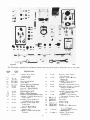
Figure 2
..
-
••
r:.
•
S2
so 11
!
Oil
-
0
.......
29
2$
"""
•
'
·-
44
NO.
• 2
• 3
• •
. �
• 6
• 7
TOOL
NO.
0·111
0·116
0-116-3
0 ·116-1
0-116-2
o
..u;
1).120
S4
Lo.Maller Reflr Pinion
Rearing Cup
Scooter Gauge
•
Arbor
Pinion Height Olock
Arbor Discs
.Ma.ster Bearina: Dirf�nttaJ
9
0·128
0.131
0·1<1
0-142
Dial lnd'ica
tllt Set
Puller - Slide Hammer
Installer· from Sp ind!c Dushmg
D-IM
Installer - �"rom Um.ko llub
12
13
14
D·ll>l>
]]
42
�
4]
..!
43
1) · 195
••
�
10
·
]2
Model 60 tronc or Rear u:le7
DESCRIPTION
1>-268
II
•
23
......,
8
10
•
•
•
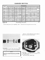
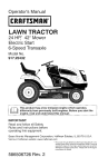
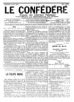
TtMI (ol&o-ll'll Ita detailedli$t of all tpeclalltn'ke tool.! required c;o aenice•
ITEM
'W · 34 · 601)
2S
,.
45
0
]6
·-··
30
�
27
il
p
'
-
28
, , , . • • • -r=
156
•
A
11 ·118· &0
48
0
20
•··
•··
.
..
•
•
. ..
s
•
-·
Master Pinion B
*k
ln$talle< F ront S plndlo
:\eedin« Beari ng
17
0-162
18
0-103
19
1}..164
20
21
0.167
0.192
22
0.194
23
C-452
•
lnstalla - Ki!'lg Pin Oe•ringCUp
meavy Duty)
Inner Bearing CuJJ IR(!�.)
lnstaUer- F'roni Brnko Hub
24
25
26
21
00-914-P
00 ·91 4·1
DD-914·8
9
00·9 1 1 ·
00·914-4 2
DD-914-62
Grease Seal
Uleg. & Hoa\'y Duty)
28
Bearing Cup
90
C-293-37
31
C-309f>.A
16
D-168
Removt>r -Front Pinion
16
0·181
Insulle.- CJooed lieU Spinello
Bushing
29
•
•
Rcmcw"r
•
Rear Pin ion
Dc1•rlng <"up
lnst-.ller • Pinion Oil Seal
I N rtt kutlll l
ln lltt�IJcr. fllnlon on Seal
tChk••ttO Rawttidel
Sproadt:-r Differential Canier
Rem0\·f1' &. lrualler - Tapered
KIIIH Pin Upper BaD
Joint Ph"'t Stud
•
lnMalle:r - Steering Knuckle
._
.. Deering Sool
RemO'\-er - Unh-ersal Jolnt
Compnmon fl� or Yoke
Pull�r Preas
F.xutn_,ion
Reducer Ring
Roduccr Rlng
Oulton
Ad111Jtcr Set· Differential
nes
H('arin
A: Co
Se
t
Ad11ptet
· Rear Pinion
�·ring Cone
lna:Wier Re-ar Pinion
•
Bf.arir\{1Cone
ITEM
NO.
32
TOOL
NO.
C-3181
33
C-3718
34
C-4025-A
3�
C-41l'l6-A
..36
...
37
..38
••39
.... o
••.u
.,.... 2
......
3
SP-320
SP-Wl7
S P- 50 26
SP-5
HO
SP-5-1·11
SP-6-113-A
D-196-2
0-196-1
..
1>-193
46
C...S24-A
46
47
C-4063
DD-994
•8
C-4170-A
OEScRIP110N
Wrench .. UaJwrul Joinl
FbmgeO<Ycte
m.Wier- UaiverulJain<
f1an!<eorYoh
!noun..- - l>.!fllftntlalSide
lle..-inp
Installer· Axle Shaft Outer
Oil SeaJ
Waabers
49
5<)
C-<�171
C-<1203
$1
D-232-1
D-247
$2
$9
$4
$S
Ad1tpl.<.•r Ring
Bolt$
Adtlptcr Ring· lnsw.ller
Adapter &I. .. R.emovin.a:
Flange Pltte
�lnstal.lft - r
ron
t Ax.le
Dilferenti•l h�Mr Oil Seal
TorqUit WN'neh ..
1>·248
1>-233
o-zo&
I)-16M
66
67
68
D-267
D-261
59
D-268
60
D-263
Haod.l. Unh"ft'S8.1
lnJU.llef- f'i'Oiol Pin.ka
•
•
8eeriDg Cup
Rema1.-er - Bearin�t
lnstalJer - Pre ss
ln
st..a.U
er - Bearing
Installer - Oil Sea1
Cup Remo\'er
(Hub & Dru mI
\"'heel .Bearing Wren<'h
Cup Remover
[n!ILaller - Cup
(Out.er-Hub & Ro«<r)
lnMa11e-r .. Cup
llnner-Hub & Rotor,
Seal l:nstaller
Set.d.ruc Gaup and ltaSler- OUftr�ndal
Bearin& Kill).ll�
A.d. Shal\ 8Hnng R•moW!g and tn...umg
• Pinion
WInch Pound
Torque Wrt:nch 100 Fool Pound
Torqoe Wrench ·
�
•••
K U W-349-601>.
Inner Axle Shaf1 �aJ Installing Ki t 0 -t95 .
NOTE; Torque Wranchet D-193, C-SZ.-A, c-4003.
and 00·99" a re optionaJ and can be purcha!M'd septlrALel,y. These torque wrenebet
ore noL lnc:h1d0d in the OW-60 Ax le 'T'ool Kit,
300 FOOl Pound
Torque W�nch
1000 Foot Pound
Wren(h Whoc1 Uellri ng
Loc:k Nut Adjultins
•
•
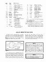
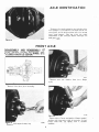
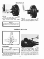
AXLE I D ENTIFICATION
lhe ukt. 1bt next number is the pan (bill of
mattriaU number. The six igit.s
d
reading from lei\
t.o right i.J the bulc number for i dentifying the
partieular ul• u�tembly. The 8Je\•enth digit follow·
i.n8 the da&h wUJ IOOnllry ratlo, differential and end
yoke optioM ut t..-d n
l the a.'ISI'Hnbly.
A1J Spk:er a:lles are ldent.i.fied .-iLb 1 mt.nuf..c·
turil'll' date and the complete P*Jt nwnber NMped
Jn Lhe right hand tube. Abo oath W e oontainJ a
J( Olt ratio tag, and if th� nle i.e equipped "''ith a
alip differe ntial, It wUJ ce�r��ln a tag
SJ)�Itying l.he use oftimit.ed Jlll ip lubrkant.
Urnited
NOTE
ln the event there are two buDd dates, lhe
lat&« wDJ be lhe da\e in w bir.b the brake
component� weN auembled. The nutllber
stamped n61. LO Lhe manufaduring date is the
comple.\e ule ._.tembly put number.
lt is recommended that when referring � tbe
ax.W, obtain the comp)ete pa.rt number and
build dat.o. 1'o do l.l'll111, It may be n�ry to
wipe or Knl))e off tho diJ1 �e., from the tubo.
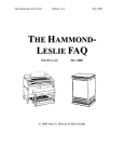
Flgur• 3
Jn thl.fl figure the ax1e is identified with 1/8"
13.l7 mml high numOOrs st.ampcd ln tho tube. For
E.x.ample: The manuft�during dnt41 o r bul
i d d.tne or
the ule it interpreted as follows. Tb• first numbf,r
t. the month, !leCOnd number it tha d1y of the
month. the third number it th• )'O&t, lhe letcer is
tM thift, and the last number it&he lice that buih
N OTE
On lro ot driving e.xl e., the above numbers
be ie
the r on 'he tMc: or a
bo rt tube.
5
c a.n
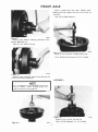
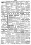
AXLE I DENTIFICATION
The gear r111lo U•ll lsloc:atcd on the left. aidft of the
cover plate/or tll t.ho houom left hand side of the
cover pl�te, fin d Is held in 1>lace with one or two
con.'1' plate 8er'eWll. Thlt tag gives t.be tooth
comb.irut.Lion of the l'inR and pinion. and also tbt
toc.l geAr 111
ti 0
•
.....
Flgu,.•
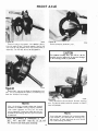
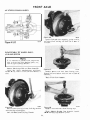
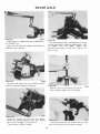
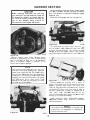
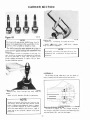
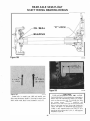
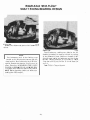
FRONT AXLE
DISASSEMBL Y AND REASS E MBL Y OF
HUBS , DRUMS, WHEEL BEARINGS , ETC.
(CLOSED KNUCKLE DESIGN)
101W'
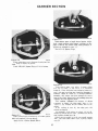
Figure 1
Remove nut-5 and Wfl.5hC!N! from drive flange
studs.
5
Romov� wheel rrom drum assembly.
Figure l/0
101...
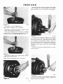
Figure 8
101t.t
Remove dri\•e flange and gaskcc.. DI8C*:rd ga.'lket.
Replace with new one •� dmt or asttemb!y. To free
Range from bub, lap lightl.y ••it.h a ra•'hide
h.ammer.
hub cap and SniP ring-.
6
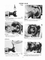
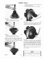
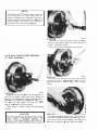
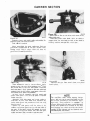
FRONT AXLE
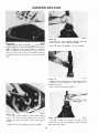
Remo'i'e greue ••I ed inner bearing cooe.
Di9t:ard sal and rept.ee .Uh new ooe tt time o f
assembly.
'
Tool: fD-131 Slide u....,.,,
��
Ftgure t
Remo\'6 outer lodmm. lodaing. and bmer wheel
b8rinR .cf.ju.tlirlg 1Wl�
Tool: ofC..I l70 \\'lbeel Wrench.
Figure 12
R l"lllO\'e
1o1t•U
i.nncr and outer whccl bearing cups.
"fools: 10·266 Cup Remover, IC--4171 Handle.
"""""
Flgu,-e 10
lk!move dmm assembty. Out.er "''heotl bcarin,g will
&lkt. ouL as drum is re.tna''cd.
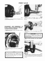
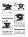
ASSEMBLY
N OTE
111 neoessary to replao& bftl)co comtiOntmt.a
such as drums. sho(!a, b11.ckln4f pla.\0, tile.,
refer t.o vehicle service rtW�ual.
If it..
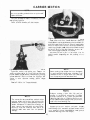
Flgure 13
As.1emble outer whe«l bearing cup.
Toob: IC-402SinJ\aller. IC-tt7l Handle.
Figure 1 1
7
to••u
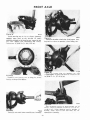
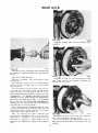
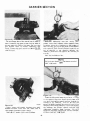
FRONT AXLE
A8:8emble hub and drum onto spindle. Pack outer
wheel bearing with specified grease, wipe CJCC\\ss
grease around the rollers. Assemble ont() splodle.
Figure 14
Assemble inner whee1 boo.rtng cup.
Tools: flO.Ill lnstaller. IC.4171 Handle.
Distribuw a sufficient amount of grease inside
t.be hub between the bearlng cups.
Pack i.nner bearing cone fuU wil.h the specified
grease . Wipe the excess gro&�e around the roUers.
Assem ble inner wheel bee.rlng cone into cup.
10rt.11
Figure 17
To adjust wl1�l bearings, torque inner adjusting
nut to 50 lb. Fl. 168 N · ml lO sea� be�rinp. Rotote
hub. then back off inner adjusting n\lt (InC fourt-h
Cum maximu m . AssembLe lode washer, t urn nut to
the nearest bote in wuher. Assemble outer locknu�
and torque t o 50 lb. t't. (68 N•m). Final bearings
ndjustmenl to be .001"-.010" 1.03·.25 mml tocal
�od pJIQ'.
'fuols; IC-4170 Wbeeii:Jenring Wrench .fC52•A
Torque Wrunch.
,
$0t,.,o
Figure 15
M&Omblo new grease seal. Apply a smaU amount
of grease t\rOUnd lip of 1S18UI.
Tools; NO·L65 Seal Installer, IC-4111 Handle.
101•·n
Figure 18
Assemble new gaskel, dr•
h e flange. lockwashers.
a nd nut.'i. Refer to Vehidc Service: Manual ror
proper torque apecificat.ions.
Fi gur e 16
8
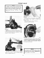
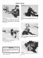
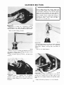
FRONT AXLE
101 ..
21
Figure 21
Remove spindle. Tap i
l ghtly with a mwbide
hamm e r to break the spindle loo&e from the
knuckle.
tOl..t l
Figure 19
Assemble snap ring and hub cap. 1'ap i
l ghtly with
hammer t.o seat hub cap.
l
DISASSEMBLY AND REASSEMBLY OF
SHAFTS, SPINDLE KN UCKLES, AN D ETC .,
(CLOSED KN UCKLE DESI GN)
Re.[Oovc wheel, hub Md drom assembly as shown
in Figure
Figure 22
'Place spindle in
diameters.
6 t.bru 10.
tot•n
vllle, do
not loe�te M bearing
CAUTION
sure that the vi&e jaws are equipped with
brass protectors Of' similar type to proWd the
machined surfaces of an)' parts thut ar c w be
placed in &.be vise.
Be
Remove bronze bushing with slide htoomer
puller.
Tool: 60-131 Slide 1-lrunm(lr,
101 ..20
Figure 20
Remove backing plate 9Cl'ews and rc:movc ba<:k·
ing plate.
NOTE
Figur
e 2'3
Rf'move (ott.er key and loosen t.ie rod nut. Tup on
nul with rawhide hammer to break the stud IOO$�
from lbe steering ann. Aemove nut ttnd dlseonnecc
f.ie rod.
Tbe brake backing plate assembly can be
reull.ned wiLh screws or nuts. lf the n uts are. of
the torque prevailing design. the)' arc to 00
replaced with new one-.s.
9
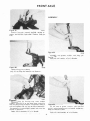
FRONT AXLE
tO'Iw•
Figure 24
Remove �weh·a cap screws, two re&.aioer plates,
felt seal, Md oil seal. Discard retai:ocr plates, felt
seal, Md on seal. Replace with new ones M time of
as&ernbly. Cut tell seal in half to disassemble.
Figure 26
Remove
knuckle
from ball )'()ke.
CAUTI ON
Tho bottom beating cone wiU fall Oul M the
knucldo is being tt>..moved. To prev�nt d-.mAge
to the bearing. eateb it with ha�Sd.
101�5
Flgur& 25
Remove four cap screws t'rom the bottom bearl.og
tap. Use a eercwdriver to loosen the bear il\g cap
from the knucltle U occt..'SMr)'.
t01f4:7
Figure 27
Place knuckle. in \'ise u shown. Remove stoor ln.g
1\rm. Tup lightly with a rawhide hammer to free i'
from tho knuckle.
NOTE
King pi.n bearing preload shUN are located
bctw�o lhe bottom bearing eap and knuckle.
Wire .shims together as they will be used
duril)� &Momb)Jo. Shims may stick to eitbe.r the
knuckle OY bearingcap. Be sure you ha,·e them
aU collected.
NOTE
Some axles are equipped with a eonstanl shim
pnck bctwoon the stee ring ann bearing eap
n:nd knuckle. It used, this pack is to be saved
and reu.&ed during nssembly.
available in thick nesses o i .003" .
.005" , .0 1 0", and .030 ' ' (mm . 08. .1 3 , .2 5. and
.7 6). Rem
( )\'6 We s haft j oint assembly.
S hlma are
10
FRONT AXLE
- R..,nO\••• lcl••l piD b<wing<Ups from
.........
.......
tpborbl boll
WIN ,
F"eg
u
re 31
A.ssem bJe ne• bronte bu:thing into ball yoke
Too&.: #D-I6t r....n... �e-�m Handle
•
Flgu,. 28
Remove bronte buahlng from ball yoke.
Tool: IO·L31 Slide flwnmer.
......
Figure 32
Assemble now felt ov0r 1pherl<:al
ASSEMBLY
F igure 3 0
AMemb)e new king pin bearing cups
•pherkaJ baD yoke. Use tOOls aa shown.
TooiJ: 10.1•2l.n.Aaller, i'C-4171 Hancbt.
Figure 33
ball
llB
shown.
101'-JI
As:semblc new oU ttal wiLh the meta) part of the
sea! towwdJ the end ofthe axle. Spread $plit of IM'.al
just enough to alip ovt"r the tube of the ule.
11
FRONT AXLE
Aou r• 34
Loc-a1e
Motring arm. i a 'ise as
s�1\.
,. ,....
Aaetmble
tftNI'
Agure 37
"-mbltknudle10 bell yob. llold bon4m boor ·
ing tn.ew) a s shown � prov.nt it from falling out.
-·• ohlm poclt lo tho knud<M CU uoodl .
A....,.blo knueklolotbo-.ing.,.. Aooem blt the
four nu'-. li«h1cn nuc.s •h.emacely and f!\·tnly.
Tcwque nut.!! •o 70.90 Lb. Ft. 196-122 �h'n).
... ....
bou.om k£n,g pin bearing cap, with
rJrelOtld .shimtt, �md four c:np IICTewa:. Torque t9C:row.s
IO 71).90 l.b. Ft. 19$·122 N•ml.
to1wt
Figure 3 5
A8!M'mblo new bcu.ring cono to king I>In, Krf!3&c
bet�.ring with 8p<.'Cl6cd grease.
101we
Figure 3 9
Place a torque "''rench on 8lcerlntc ann nut a.s
shown. Torque to actuate knuckle to 9-15 lb. Ft.
112·20 N·m1. When choo:klntc: I.OI'que rotation of
knuckle. make sure IJe rod and seals a.re not
'"..
*'
Figure 38
"-mbko ule oboflloint ......,.,�y Cnc.o ho<aalng.
assemblNI to knudtle.
12
FRONT AXLE
NOTE
II prelood i!; 1.00 light, correct. by addlng shims.
II Pft-lold Is loo klote, eorrec:t by removina
abimo. Plttoo.d .rum ...... is locotod "" the
bouom bec.,.·om the bNM.g c.p and buekle.
Sb.imt are a\•a.Uab1e In thlekne8ee• or .003'',
.001)", .010", nnd .030" •mm .06 13, .25,
an d .761.
•
.
Figure 42
Position
new
'"..a
tpl_ndle in nse .. ahatm a1.ICI a.uemble
bu.!lhing
Grease wide
.-peeified greue.
of
bushing with
Toots: 1'0-141 lnst.&ller, IC.4lil Handle.
A3&emblt tpind.le to knuckl•.
Figure 40
..,..
A&��emb1e new oil!M!II lnl.O knuckle. 0. sure split
or seaiiJ to the top of the uJe. Aascmblo new felt,
two rc,.,lncr plates and �welve cap tercwa. Torque
screl'!e c.o 15 Lb. fl. ( 20 N'·ml.
1011·0
Figure 43
Assemble br1ke backing plote assembly. Reftlr \0
Vehicle Servic.e Manual for •p«ified screw &orq\M.
Remove
iM)l«'doa plu,g
f'rOI'ft knudde and fill
h�\<el to Lht! p1ug hole with specified lubric:Jr\1..
Assemble in.IJ>CC:(.I<m ptus.
N OTE
To set �In refer tO Vthltlo Service
Mano.al.
Adjustmenu can be madoo by loooeni•a clomp•
oo LM tie rod. After proJ>er •djusunerKt •re
Flgu,. . 41
••-n
ASMmble tie rod tO steeri-ng ann for 5peci.fied
torque on Lie rod nul, refer to Veh.lclc Sorvi.ce
Ma nu fll, A8st.mble 00\l.Cl' key.
mt�de, �tighten tie rod ciAmpt.
13
FRONT AXLE
40• STEER SPRING LOADED
Fi gure
�t-46
Figure 46
Remove bub n.nd rotor tt.3SCmbly, .spring retainer
and outer wheel bearing will slide out as J'O'Ot is
removed.
44 L I D
DISASSEMBLY OF WHEEL ENDS
HUB AND ROTOR
•
NOTE
If it. i.s n�sary to replace brake components
such as di.se brake pads, backing plate, et.c ..
refer to VehiJce Sef'\•ice Manual.
Remo\•e Wheel from Hub and Rotor AS!Jembly.
f'oltow the ohkle mo.nufoc,urers reeommen·
dations !or lhe rurruMll of Lhe hob-lok aasembly, if
used.
to'"'"
F'lgure 47
Remove grease seal and inner bearing cone.
Oisca.rd seal and replace with new one at. time of
as.sembly.
Tool : lf>.lSl Slide Hammer.
...
1C1 ...a
Flgure 48
Remove inner and outer wheel bearing cups.
Tools: 10-255 &ruing Cup Remover (outer•.
ID·2b1 Bearing Cup Remover (inner).
,�,...s
Figure 45
Ren\ove wheel bearing lock nut, Jock ring an d the
wheel bearing adjusting nut.
Too l : ND-165A Wheel Bearing Wrt:nch.
14
FRONT AXLE
Assemble new I"'M.M.eel. Apply a small amoun•
of �toe around b9 of ft.
Tools: 11).2f>il Soolln.ololler.
RgurtG
Atetmble oute- ·�
Toolt:
IC-4171 Handlo.
...,...
btarin,g alp.
10-23<t lnSilaller.IC-4171
Hanc:llfl.
Figure 52
A3sembJe hub and rotor Ol'lto 3pi.ndle. Pack outer
whee) bearing with spociftcd gTeu5C, �Aipe exc;e••
grease around che rollers. AJS('mblo onto spindlo.
Flgurt 50
A.'&<�mble i.nne r wheel bearing tup.
101•eo
Tools: ID-266 lnstaJJer, .fC-4171 ll��ncllo.
Oitrtrlbute a suff i cient amou.nf. of groue lnrilde
tho hvb bl'tween the bearing cupt, l)fteli l.nner
hfotu1ng oon� full witb r.he .spoci/led grua•o. Wipe
the t'xc:ets grease around lh6 rollers. Aue:mble
l nntr wh�l bearing cone intO cup.
101t-N
Figure 53
To ..:lj� whetl bcartngs. torque Inner adjWJLing
nut tO bO Lb. rt. (68 N·mJ to seat beari:Tlgs. Rotate
hub, then beck off Inner adjusting nut one--fourth
tum m.aalmum. Aaftomb.. kick •-asher. rum nut 10
nearest holeIn •"aalhe-t. Aaemble outer kd:nlJl and
wrque ro 10 Lb. Fl 168 lh>l. !'".W beartns•
adjustmen& co M .ocn-.010 t.�.25 mm, coW end
play.
'fools:ID-166A Wh� el Be•rlng Wrench. #C-612A
Torque Wrenrh,
N OTE
Figure 51
For servicing iplndkt and knuckle, remo\•e hub
and drum u deecri\)@.(1 in fi gures <IS throu.gb
<7.
......
15
FRONT AXLE
Figure 54
Figure 56
Remove four nuts on steerin g arm. Remo\'e nuts
alternately as compression spring will force steering
arm up.
101t.M
Remove spindle. U nCOOMA ry, t.Ap UghtJy with a
hammer t.o free it- from t.hc knueklo. Chock
bronte $p&:;Cr locau�d between axle she,(l. joint
rawhide
011 scmbl.y
and bearlng. U wear Is e.\·ldent, r eplaee
whh « new ooe.
10tt
47
-.-:-:J
Figure 57
Remove steering arm, compression spring. and
gasStet. Discard gasket., replace with new one a t.
time of assembly.
tOtwo
Flgure 55
Place spindle in vise. Do not locate on bearing
diametgn;. Remove nood.lo bearing.
Tool: ID·l31 Slide HMtmer.
CAUTION
J:le I!IUrt. thaL vl&e jaw$ are equipped with h1*88
proteot.ONI or Himllar type to proteot the
machined aurlaeea of any parts that. are to be
placed lh the vise.
101t.S&
58
Remove £our cap s:c:rews on bearing cap. Remove
hearing cap.
Figure
Remove axle shaft jon
i t. assembly.
t.o Figure 23.
Remove tie
rcxl. Refer
16
FRONT AXLE
ASSEMBLY
\
•01we
Flgurt 59
Remove king pi.l'l tapered bu.thln.g. tpring te·
•
I
'
&aln�tt. and knuckle from yoll;e. ReiJ'IO\"t king pin
.-).
IOI....wl
Figure 62
Assemble new greru�e rct.aincr and lOng pin
bearing cup.
Tools: 10-142 IIIOUII«, IC-4111 Handle.
Figure 110
Remove king pin
......
as !'i:howD.
Tool: ID-192 King Pin Installer •.nd Ramo\•er.
q
I
Fi gur e e-,
,,,...,
Ucmove
tcing pin bearing cup. c:ono. grease
r(ltfl(nor. t'lnd tlhl �� 8l the $WD(! time. A11cmblo
M d u&e tools exnctly os 3hown ln Flgurt' G2. Di8C8.rd
lt!ll and replllee with
*" timo of al!lembly.
If gree� ret.Ainer t.s deunaged. «!PIIICC with ne"'' one
at dme of •s!lembly.
101t.H
Figure 63
Fill the t�rea ln grca.-.e relainer with specified
grease, grea11e belling cone and lnsialt lnsr.all new
king pin bearin� on tell.
oew one
Toob; fO.Ul lnstaller. IC-.4l1l Hand'e
Tools: 10- liM lnt4all.,, tC-4111 Handle.
17
FRONT AXLE
f
.......
Figure 84
tnoull m.g pm. To<q\le mg pin 10 - Lb.
Ft. 1673-313 N·ml.
Tools: ID-192 Ki.ng Pen ln.s&aller and 8e1DO\"C!t,
IDI).994 Torque Wrentb.
Figur• .r
10'IHT
Assemble spring retainer and c»mptUSioo spr:inJ
king pia bushing:. Asgemb)e -.oenng arm. •-ith
new gukt<. mer four JWdt, 1lghten nuts
a1temaW1)' and 8\'enly. Torque nu" 70-90 Lb. Ft.
195-122 N·ml.
on
- ·.... ....
'"...
'
Figure 65
Assemble {olt. $hi to king J)in. M$Ctnbl� knuckle
liiJ!Iemble tapered bushlng over ldng pin.
Figure 68
�e.mb1e new needle btturing Into 8pind1e.
Tool" ID-2681n51aller, IC--4171 Ho..U..
'01....
Ftgure 66
Aasllmble bearing C(I!P wlLh fou.r ce:p 8CtCw&.
'Nghl6n eap a<:rews oi�,.C.rmucly and twool)'. Torq"e
.. Fl. (95·122 N·mt.
cap tCrowt to 70.90 T b.
Tooh IC.02..,.A Tor<lU6 Wreneh.
101.,.,
Figure 69
AsHmbla greue seal lnlO .!l�'lindla. The lip of the
seal is to M directed away from \M tpindle.
18
FRONT AXLE
Figurt 72
101�
Pad lhe are• around the thru.u fac:e area or t.he
obalt lDd OMII.Uol,_... Abo. fill the seal""'"
o rthe $plndle ..-ll.h pt�Ue.
Figure 70
..,.,,.
Som� front axles are equipped with n "V" 80&1,
whkh 111 usemblod to the axle sh.at\ 8COno shield u
lfhown. H seal i$ wom. remove and ropl.w:e wi\h a
naw one.
Figure 73
to•n
Assemb le a.x.lo stutfl. jotnl. a.s&embly into housing.
10t..M
Figure 71
AJMmble new seal asshown. Up of lh• eeal is to
be dlt'Kt«l towards the spindle.
Figure 74
Auembte new bronxe tpa.«tr and spindle.
L9
��t�..u
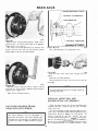
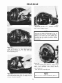
REAR AXLE
REAR AXLE
Unit wheel bearing design Jubric:O.led wl'h hypoid
lubricant.
NOTE
Vnit. wheel bearings that are dependent o n
lubrication from the bypoid gear lube in the
rude housing. rather than grease, are not
equipped with an inner axle shaft oil seal as
shown in figure 75.
BRAKE BACKIN G
/;
/r
-
,"'
Figur& 75
tot..n
Figure 77
Removo bacldng plate nut s which hold the brake
b3clci.ng plato t.O the taxle hou!J.ing. DLOJCard nuts,
roplaee wi'h new <metJ a.' tlme of tLS$embly. Nuta of
torque prov liilln.s: design a.re n<K t.O be reused.
SEARJNG
BEARIN G AETAlNER
.---unt.n
Unit whool bearing l./0 without Inner grea$e
...
J.
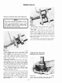
DISASSEMBLY
'
Figure 78
10tt. 11
Remow> the t��;de shaft by pulling on the axle. lt
ml)}' be n(.'CCS.Stlry to free the a.xle shaft by prying it
ktose with two serewdrl\'er:s or pry bars
as
shown.
N OTE
Bt\cking plate can normally be wir-ed to the
frame, without loosening the hydraulic broke
line conneaion a t the wheel cylinder. if
desired. U se caution to avoid damage t.o brnkc
line.
101•1•
Figure 7 6
After wheel i s removed, remove brake dtum.
20
REAR AXLE
Figure
80
,._ml>le
assembly.
....
..,.
b.dona p!M<! boka and beckmg plate
FJaur• 19
.,.."
Tho beorin« cup wW .,.,..n,- 111&1 In p- with
\h@ houth�. To temO\"ebearing cup. UN puller N
ah.....
•...-t
Figure
Als&emble bearins t'up into bearing bon� of th e
tube. Make su.re Lh@ CUI) backface i s against lh�
Tool: i'D�I3J Slide Rammer.
C1eanlng, inspecting. and re.JubrlcatJng wheel
unll bearing.
Ctf.lvn bearing cup with any or tho �tl\ndard metal
ch�c�u11n g 501vont.s. Inspect cup (or any PQSSible
wen.r, nkkl, etc.
The cone assembly can be
bearlng Sl'Pt o( l.hC! bUbft,
cleaned in place on the
�tde thaft. Us� a.n,y standard met.al cleenin.g 10h•ent
and a ttlff brit�tl� brtl.!-b to remove any dirt o r an,.
other contamlnal5ootbu might be prMtnl, then UM
air. Air eboukl be direcucl at the cont
U��P�T�bly .a that il pet throu8fl the bterln.g ftom
OM end of t h e rollers 10 lhe otbtr It Ia imponant
001 to "Spin Dry" the be#inl-.ilb t'Ompruud air.
Spirtninc the dry be&Jin8 � 8C'Ore lhe raceway•
tf'ld roUcrs due to laek oflubrbnt.
U80 • IJlandard metal cleaning tol�t to clean
ou t tho bearing bore in the hQU'JIIn(C. WIJ)& Lhi!l a.N!a
clce n mnking sure i r. i s free from dirt or e.ny other
conlMhunlon t.hnl might be prese.,t.
After the bearing has been in'IJ)t)CL«i and
compr�ued
1011·1l
i
F t::�:t. axle thllft.lnto hoWling. Care should b e
taken nol &.o damage \he bN.ring roUers.
Line up the hoi., or \he retain<::r plate wilh the
bolts, pu!Sb ule Wft tmo th� bou,.,ing aa tar- as
tlpJ)roved for continued. .service. it must. b«,� lubri·
cat.td pr'ior to inst.all ation. 'The Marilij( muat b e
1ubrk11ted by appl�'ing • .smaU amount of the
tp«ife
i d lube
4U'OW1d
1M rolk!rs or Lh e bearin g
--
�le .
!I
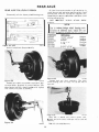
REAR AXLE
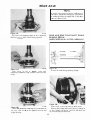
BRAKE BACKING PLATE
OIL SEAL (QUTBOARO)
UNIT SEARING
=
1ol••tt
Figure 83
Start nut.S on backing plate bolt.s by bl\nd. Use a
speed wrfJneh a� shown and ti,g.htcn (.(1 eppt"Oxi·
mately 16 l.b. fl. (20 N·m).
'Olo unts
i should be ti.ght.ened in fl manner that
assure� tha t �he seal and eup rib ring tlrC dr awn
tw<Jnly against t.he cup
housing.
OIL SEAL (INBOARD)
BEARING RETA INER
Figure 85 l/ 0
Unit wheel bearing 1./D with grease seal.
in the
/
Figu re 86
Remove inne r wdc shalt. seal U..'lin g puUer- a&
sMwn.
Tool : 80-131 Slide Hammer.
Discard M>al and reJ)lace with new ontl at. m
it. e of
assembly.
101.....
Figure 84
U!l'iilp: a torque wreneb 3S shQwn, Wrque nuts 'o
Ft. (34-47 N ·m•. Assemble brake drum&.
retainer nuts. wheel&, ott.
NOTE
20·35 Lb.
Avoid contneting seals w ith cleaning solvent in
c.leaning operoLion.
1'ool: �524-A 1'0f"quc Wrench.
CLEANING, INSPECTING, AND
RELUBRICATING UNIT BEARINGS
Clean beal'ing c up -A:i'h any of Lh� stMd3rd met.al
cleaning 9(llvents. Inspect. cu p for t\nY possible
wear. nick.<l, etc.
TI1e cone assembly con be cleaned in place on the
shaft. Use a standard met� cleaning $01vent ar.d a
$tiff bristle brush to klosen the old grease. To
ensure removal of the old gTease and any
contamination that might be p
re sent, use compres
sed air. Air should be dil'ee te
cone MOO:mb1y
so that it goo-� l.hr()Ugh the bearing from one end of
the roUers t.o 'he other. tr. is impon.ant not to "Spin
UNIT WHEEL BEARING DESIGN
LUBRICATED WITH GREASE
NOTE
Unit whecl beari ng t.hat are dependent on
grease for Jubricatior�, raLhe.r than hypoid gtt\r
lube from the axle housing. are oquippod wi"t.h
an nn
i er aJCie shaft oil seal as shown in figure
ss.
d at the
22
REAR AXLE
Dry" the bearing.,ith c:oaJ.passed alr. S plnnifll the
dr)' bearfna may acore the racewa13 and roUen due
l4 the l.t:k or lubrica.at..
Ute • sundard meLal deanin& .oh�l &o ('lean
out the bM.ring and o il eeal bore in \he housing.
Wipe thia area eM;-an. making sure 1t It free from
ot.am
that might b e
MY old grease or Other c::oination
prtscnt.
Mt.er the
l1J)J)rovod ror
bearing hru bet->n in!p«tcd and
continued service, it must bo lubri
ttd.ed prior to iMtalJt�tlon.
1'he J:rea� Rhou1d bu a good qualhy number 2
E.P. (l:xtremP Pressure) Lhhium MlC'p. wheel
�anng h'l'ellM!.
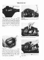
.,....
F1gu,..89
After \be avily lt fuU of grease. tiii'Tap tape
oomple«>lyarouncllho rib rin3 ond oc.lu shown 1<>
coclose the-ca,.,�,.
*H1
Fl9ur1 87
Pu�h teal and rei..air.:er away from tbe burinA: l.O
...now • cavity betwee n the $el1 and boulna.
101wo
Figure 90
\\ith lap(l etW wr�pped around the ring, pu.5h
seal u-p until i t content the rib rin g. ThiJ will fon:e
the grea.se up throu«b lheroUers.
NOTE
F1gure 88
rill the Arta or cavic:y between lh•
bHring with the recommended peu..
'""..
18al
and
I f grco&e U. not apparent on .,m.all end or
rollers, repeat thete uep:!l until gru -'JO
appe�.
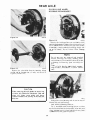
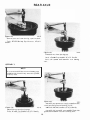
REAR AXLE
101"''
Figure 91
Remove
bodies.
tape and wipe excess grease
Figure 94
on roUer
,o,..a.
A$$Cooble boaring eup lnto bearlng bore of the
tulJe. Make sure the wp bfld(� is "gainst l.he
bearing sent of the tt.�be.
ASSEMBLY
Figure 92
101wo
Figure 95
Assemble ade shaft lnto hous-ing. Care should be
taken not to drun�-e \he seal lip and bearing rollers.
Line up lhc holes of 1.he ret.aine!' plate with the
bol'-'; push �Uele shaft into the boulring as fnr as
pO<Sslbl••
1tnt.tt
Asscmblc. new grease. .seal inw boubing.
Tools: IC·4026A Seal Jna�aller, .i'C.•t71 Handle.
After seal has been assembled, grease Up of seal.
Figure 93
Assemble bl'lddng
101t.t6
Figure 96
Start nuts on bacldngpltlte by hMd. Use a speed
wnmc:h as shown Md lighten to snug fit..
1�..n
plt�te bolts and backing plate
M&embly.
24
REAR AXLE
......
F5gure99
After drillins <he me.
-
Ute a torque wrench md \orque nuu to 26--M Lb.
n. 13H7 N-mt.
• em..! posilioned
the bole andatrille aharply lO break the ring.
Di$C'&nl and repl.lce with a t"'eW one at time of
e(rOS8
Figure t1
....
a.59embl1.
REMOVAL OF UNIT BEARING
FROM AXLE SHAFT
NOTE
To d:IHSMmble u:Je shaft from houtina. follow
d•• pl't'Ctodures illustrated tn figures 76 Lhru
71l
Figure
,.,..,.
100
1\asb retainer plate and seal towards Oange of
a:de shaft, lnmU tho 0ftngtt plate to the flange of
the axle tlba.f\. lnaall bolua lnt.o Oanf.-e plate. Slide
forcing t)1ate ewer the ado shllh. lnstaU the
adap ters solhoy aoat under the cop rib ring.
Gradually �Jgbtcn tho bolta until tboy are located
in the dimples on l.ho backside or the forcing plat.e.
Tools: fSP-�43-A Flonp Plate. ISP-6017 Adap
<tt Ring. fSP-5542·0 Adapters. ISP·5026 Bnks.
nghten boha of tool ahenwely unlD ��
is removed from !We sha.fi. Be careful DOt t.o
mark the rD��Ch.lned �rflltft of the a:de WfL
cone
CAUTION
Do DOt bea' or nt Lhe
uu.....
Fi
gure 9 8
l·'laeo axle shcUt. in a \tise. Dri:ll a 1/4" 16.35 mm)
hole In the out!tlde o( the ret.ainer ring lo a dept.h
lll)f)ro•lmatley three fou.rtb.s t.hctkknett of Lhe rfna.
Do "'" drill all the ,.., <hrough <be rt
••, lbe drill
could damage the axle shaft.
bearirt« eoae U8embl,
with a �reb to rtmov•. Dam.e,ge to the ule
tha·l't will ro11ult.
Remove seal and retainer plate. Oiseard aul.
Replace with nt�w one •t time of flS&(>ll'lbly.
lnsP«:t r�t.tdm.u pll\te f(lr po88iblo distortion.
Uany purdon o' the rtt�Jlner pl•tc is damaged,
it should be repl•oed. lntpec:t machined
su.daoe:a of the •.de abaft, audl as the &e.t and
beariftg diameter•· Cleaa u:le ahalt, remoTe
all nicb or bWTt.
REAR AXLE
INSTALLATION OF NEW UNIT BEARING
NOTE
"'llo rt'talnet- ring area of the shaft is t.7727"
(4&.01 mm) mtnimum in diame<.er, and tho
reu.inf'r ring inside diameter is 1.7676" (44.88
mm1 maximum, aDd therefore. should require
.orne 6000lb. f2666&.
'J) minimum preu &o J:.Mt
the ring apinst the uni1bearing.
Figure 102
lntWI maine�" rlna on ole abaft. Follow the
procedure. m figure 101 to U!C!mble the
re�ner ring.
U:&eb .0016" (.0381 mm• feeWr gage belw�n c.he
bearing and retainer rtna to be �ur" thuc. c.he
r\1\Ai.n�r ring tt !te'at':!d. At l�ut onG )XIint �hould
u�J&t. where the JJ880 will not. entt>r bt.-twoen che
rcc.Woer ring and hearing. If gage ent�rs complet.ely
tnound the dlamete.r, retulnor ring muSl be forced
onto Lhe: axle shaft..
To assemble axle &haft aut·mbly inlO housing,
foUow steps � illut:tnlOd in f&gUre 82 through �Arne
t01•101
101
�1angQ
should �m be assembled to tho
Oang� o( l.ho au:le 8hRft.. Remove bolla from 0ang41
plato A&S(tlnble new retainer plate and oil sea),
The rubbf.r portion of the oil seal, which oxte:nd•
beyond Lhe casing has numbers bonded In the
rubbor. The!e numbers are to faco toward the
flange of &.he a.de shaft.
M8t'mb" new uni
t wheel bearing oa uJe thaft
Slidetnteallina rin&on axle shaft. Be surt: &o loclte
unk wll<ol boonng oa the inDdo of 11>e lntWilng
ri•R· SliM loo-dng plao. "" ulo sbol\ o.nd *- ""
insuUing ri"'. tru.t.ll boiU and _..,her t.hroug!\ the
ho'- In th• forcing plat.e and ln&O flange ptate,
Figure
,..._,.,
l
pat e
LUBRICATING NEW UNIT
BEARING WITH GREASE
Tool.: ;SP·M48--" FIMge Pla�e. ISP-6017 Adap·
ter Ring. iSP-6440 Adai.)U!r Plate lnaallcr, •SP·
M26 llol\t, .fSI,-3020 Wru�hers.
'ri�tht-en bolts alt.ernateJy and e\'enly, making t�uro
bearlnl( I.J nOt oocked on axle shaft. Continue unc.U
whct!l bc&.rina it seated. To mako sure lMoarlnir is
�8wd u11a a .0016 .. (.0381 mml fceJtr gage
bet,-.�n Marlng J�Nt and bearing. U pgt enten,
forte l>Mrln.a f\U"\her on the axle sh&fl
. • untU gage
"'"'101
Figure 103
Push seal ud rtU.Iner away &om bearin,g to
aUow a c:a'\ily bet.v.-een the Mal and bearing.
doetnoc '"'*.
28
REAR AXLE
NOTE
l£ grease is not uppar('lnt on tbe fmaU ends
of
the roUers, repeat the samo $&Cps until g:rease
is evident betwoon the �mall ood or &he roller
and cup. Jtemove tape.
Figure 104
FlO cavity with a good quality
101�\1)1
REAR AXLE SEMI-FLOAT SHAFT RIDING
12 E.P. (Extceme
BEARING DESIGN
P�su.rel Jil hium
.soap, wheel bearing grease.
..
LUBRICATED WITH HYPOID LUBRICANT
OILSEAl.
Figure 105
Figure 107
(Picture or Shaft Riding Bearing Design I
•tt"'�
After cavity is
completely
cavit
y
full or grease, wrap tape
nround ri
b ring, Md seal to t:mclose the
\Git--107
.
Figure 108
Figure 106
•o•&otot
Anor wheel l,s re,novOO. remove brake drum.
Re.m<.>\•e drain plug and drain lubricant. 1£there s
i
no drain 1)108' in Lhe carrier. the lube y,.-ilJ drain out
AS the c;.over pl.at.e is remm·ed.
to1a.t06
Push soal towards the bouring unt.il it eonLact..'l lhe
rib ti.ng. This will force the grease between the
rOUe�'$ and cup.
27
REAR AXLE
Flgurt lot
..,..._
�
..
-e lht> differential ptnlon aha.ft lock screw as
cover plate sc:re•-s. c:over plat•. and
plat� pP:eot. Di1Jeard old psket. Tip canifr
co alklw lube todrain rompletely. Abo during t.hiJ
timec:lean therover face ofr.he earrier, maklnc turt
it i.!1 frH from 11\Ynicks and a:ny partJdcsltft by lh•
old gosk«. DO NOT USE CLEANING SOLVENTS
OF ANY TYPE. Use of eleanins 801w:nts may
Rfmo\t'
$hov.-n in Figure Ill.
roo.w
prevent Lhe ''RTV" sealer from adbetlng t.o tho
cover plate Md c:nrrier, resulting in leak; of nle
lubrkont.
Figure 112
10tt.nt
Remove tbe ditle•'C:'nl.illl pinion mate shalt..
'"'·"•
Clean oovcr plt1t.o. making s.ure it is Free from l\ny
nkks ta•1d �:�ny pnrticles left by the old �kot
rliAt.erlal. Ut�c 11 clean rag or a blunt t.ool for
rcmovinK renualnlng gaaket mater ial. DO NOT USE
CLEANI'-"0 SOLVENTS OF ANY 'TYPE. u.. ol
deuing aotvenu mfiJ' prewn� the "KTV" lftk!r
..
-.r plac.e and c:anler.
from adhering «> the co
resuking in lflb of u1t Jubric:ao&..
Figure 110
tOt9ol13
Figure 113
Pu.!lb fi.ang\> end of •.xle sh..
Ita: •owa.rd �nter or
�o'ehide and remove the "C" loeb from buttOr'l end
o l bo<b shafts.
28
REAR AXLE
OIL SEAL AND WHEEL
BEARING REPLACEMENT
Figure 114
1th..u•
Figure 116
Remove the bnckin,g pi�� oUt$ and boll.$ whjch
holdtbe brnkc b&cki:ng p�te to the a�le housing. (S•
pl�...:<.'S. Discard nut.S, rel))tlec wi'h new ones at time
of assembly. Nut.s of wrque prevailing design ar6
not 1.0 I>C reused. Do n()( remcwe brake baclring
plate.
NOTE
The oil seal may be removed and lnstallcd
without removing the brake backing plat.e.
nut-s and bolts. Care should be takton 50 u.s not.
to damage the bearing upon removing l.hc
seal.
Figure 115
1019-tfS
Remove the axle t!httft:l from tho housing being
('arefu) not to darnt�.ge t.be- oU seals, 1\.8 shown in
•'igures 114 and 115.
Tool!�!: .tC-4171 Handle, ND-233 Seal lnst.aUer,
Seal kemo•oer (ec::t"ewdrivcr or ocher simlhtr
tooll.
,
CAUTI ON
'When removing the- axle sh.u.lts, be direful not
to rotate the differontia1 8ide geartJ. Thli wlU
cause the pinion mat� l{e1U11 and tbru..qt
washers &.o tum to the opeo.Jng or the case and
drop out.
101t.111
Figure 117
ltemove the wheel bearing and oil seal as shown.
Discard old seal and bearing.
Tool: ND·232·1 Bearing ltemO\rer.
Use tt mndltrd mct�l cleaning solvent. l() clean
out t.be bt.arlng bore. in the housinJf. Wipe this area
dean, mt\klng 8\lre it is � from dirt o:r any other
oonte.mlnatiOt'l thAt might be present.
NOTE
'J'he OOaring bore must be freo from nich and
bum;. Wipe the bore with emery doth to
assure n smooth surface. Clean bore out.. wit.b a
standard meta1 cleaning $01\'e-n,. 1f bore has
bum or .spalled areas and a new l>otuing is
instttlled. it may lead to early ffltigoi.ng.
101t-m
Flgufe
Assemble new oil settl into housing as shown.
1'ool wi
l l st.op against Utbe end when oil seal is
seated to the proper depth.
Tools: IC-4171 Hand)e, 10-233 Seal ln$la1ler.
/
AXLE SHAFT AND WHEEL BEARING I
OIL SEAL ASSEMBLY
Figure 120
101Hl0
lubricate cavity OO�woon seo1 Ups and lubricate
new bearing wiih a good quo.lity number 2 E.P.
(Ext-reme Pressure•. lith.lum Map, wheel bearing
groa&e.
,o,..m
Figure 1 1 8
A.s��amble bearing assembly into bearing bore of
&M tube as shown. Differential lube 6hould be
plnccd on the bearing for easier a!lsembly Md for
&he po$:sib1c prevention of scoring the tube bore.
The tool will stop against the tube end when
bearing
l.s sen.t.cd to
&bo proper depLh
Tools: ID-247 Jnstaller P'ress, 10�248 Bearing
ln6taller.
CAUTION
DO NOT DRIVJ) THE SEARING INTO TUBE
BORE W
l'l'H A SEARING DRJVJ)R . AS
DAMAGE TO THF. BEARINO MAY OOC U R .
Figure 121
101t.12t
�somblo axle shaft. inw holL'Iing. Care sb{)Uid be
taken nOb to damage t.be seal lip and bearing l'()lle.rs.
anrl Lhat. tho sbnft. :�pline engages with splines of
diffetenlittl side scar:s. Do nob rotate side gears.
REAR AXLE
Figure 122
1'urque lock pin lO 8 Lb. Ft. · minimum
'fool: C-52.-t-A Torque Wrenc:.h.
(11 N·m).
NOTE
Whet:�ever the lock pin is removed. it i:s t(l be
replaced with a new one. New lock pint'! b(lve fl
Joclring type material on th& threads chat
s�ures t.he pin wben in place. Be(o�
int=nalling lock pin, mnko sure bole Is free of
din and oil.
Figure 1 23
•D•t-m
Push fi� Cod Of axle Rhaft towards center of
vehicle and install the "C'' lock. Pull Onnge out
from center of vehicle unt.U ··c.. Jock seat.s jnt.o
diUcrentJt�1 side gears.
IIJI�l28
Figure 126
Assemble backing plate <\S&errtbly. u!ring a torque
wrench as shown, torque nut.� to 50-85 Lbs. Ft.
(68-115 N·m•. A!ltoemble brake drums, retainer
nuts. wheEls, etc.
Tool:
N�24-·A 'Torque Wrench.
NOTE
t01t·l7"
Figure 124
Assemble pinion mn'c sh�ft. Re aure lock pin
hole of the shalt is li.ned up with the lock Jlin hole of
the case. A11semblc luck pin.
Refer t.o carrier scetlon for aMembty
31
of cover.
REAR AXLE
11 wheel bearing lockwasher is or the design in
wh.ich the eaNI are: benl. over t.hu Oats of the wheel
bearing nuL'!, bend e�t.r up from the outerlo ck nut.
Remove outer locknut. I<X:kwMMr and inner wheel
bearing adjusting nut,
REAR AXLE FULL FLOAT DESIGN
Disassembly of hubs, drums. wheel bearings, et.e.
Tools: 1Dl).l24l•J
Adapter.
Wr6nch, IC·4202
Socket·
NOTE
Due. to various d
esign wh ee l bearing ou t&,
wrenche s of different $lzes, which al $0 use
adapt.er C -.4 202 o. c
o s:
r avil uble and are as fo!Jw
-- -
\
IV
WRENCH
00-438
00-824
00·91 7 ·8
00·96
2
OD- 1245
D )-]
l 280
·� J
Figure 127 L/D
Remove wheel from
Figure 128
drum
assembly.
O
P
ENINGS
a -1 18'' x S-o /8"
/16"
2 -9
3-11<"
3-1/2'' X 4"
2-3/8"
.
2-3/4. X 7/8"
Oetl\gon
Ocw.gon
Ocw.gon
Hexagon
Hexflg<>n
Oct�n
101,..J»
Figure 130
Jtemovc hub and dru.tt'l asscmb t)'. The outer
wheet bearing (.'<Inc will sljde out 118 the hub is
removed.
""'·•n
Remove a.xJe shaft nuts and/or cap screws, pull
out axle sbfl..$, U gasket is present bcl.wce:n wde
shaft fi�tnge and hub, discard gasket. and replnce
wiLh a new one ttl. Lime of assembly.
Figure 131
1010·1,,
Place hub on bench and r<'movc grease seal.
Discard seal and re)llace with n.:tw one at. time of
assembly.
Figure 129
'fool: N0-131 Si
lde Hammer.
32
REAR AXLE
Figure 132
Remove inner and outer bearing cups from hub.
'foolb: ID�l62 .Bearil'l8 Cup Remover, IC-4171
Handle.
Figure 1 3 4
AS!Iemble new inner bearing cup.
Tools: C-,.308
t'
Cup lnstaUer. IC--4171 Handle.
Pack wiLh grease and assemble new OOaring
cone.
"')SSEMBLY
NOTE
lt. is recommended t.hat whenever beartng eups
and cones are removed they ere to be repll)ced
�A'it.h new ones.
Figure 135
Figure 133
A.ctsemble new grease seal. Apply a small amount
oft.be specified grease around lip of seal
Tools: 10..156 Seal Installer, IC-4171 Handle.
Assemble bub assembly onto spindle. Pac-k with
greMO and assemblo now oui.Or bearing oone.
101..1'33
Assemble new ou.tcr bearing cup.
Tools: IC.4308 Cup !nsteJ!er. IC·<In HOJJdle.
33
REAR AXLE
1ot.,,.
Figure 136
Assemble lnne.r whool bearing adjusting nut.
loc.ktl'lb Md out.tr wheel bearing b:k nut.
TooJg,
Adt�pwr.
IDD·l24l·J
Wrench Socket.
IOr..tar
Figure 137
A�mble new guket, assemble axle shu.ft,
wrquo nuts or cap senw.-s. Refer to Veb.icle Service
Mnnual for prope
r torque specifications.
KC.42Q2
N OTE
For fma) wheel bearing adjustment and torque
specUteatloM, rofor lo Vohicle Service Man·
ua1.
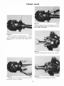
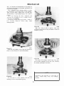
CARRIER SECTION
Figure
138 L/0 Csrrler Section
101foll8
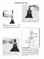
DISASSEMBLY
1019one
Figure 139
Rern<we <:oYer plate 19erewa, cover plato, and
CO\'Cr plate gukct. Discl\rd o1d gaskc�. Tip tarrier
to l\ll.ow luOO «� drain completely. AUo duri ng this
Lime clean the cover r01c�& or the c&rricr. m.l\king su.rc
it Is r�c fl'(lm MY nicks and any J)$rtleles lert by the
old gttSk�. Do r.ot. use cleani.l'lg soh·ent.s or any
t.ype. Use or cleaning solvents may prevent the
"RTV'' sealer from adhering t o t he cover plate and
carrier. resulting in leaks of axle lubricant.
NOTE
IJ it bc<·omcs noc�Msary to disassemble any
part.$ im�ide of th� carrie-r, it is suggested that
the (!l)t,i.re tude bo rumo.,-cd from the \'ehicle
nnd held t.lght. in a Ml\nd or rack.
nemove drain plug and drain lubr ice.nt. (f •here is
no drain plug in t he carrier. t he lube will drain out
as t he co\• er plate is r
em o�,o-ed.
34
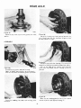
CARRIER SECTION
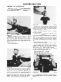
C A UTION
Before removn
i g differential case and rial(
gear, make sure tbe axle shafts are pulled out
far enough for clearance to remo,•e differen·
tial. Refer to section of manoal covering the
type of axle assembly being set'Vieed for
procedures on removing the axle sbafts.
Mount spreader to housin
g. Do aot spread carrier
over .015" (..38 mml. U98 dial indicator as $hown.
Note: This spreader can also be used on the Spicer
Model 4-t axle.
Tools: 1'0·167
Spreader, 10·128 Indicator Set.
l01,.1ct
Figure 142
Figure 140
•o•liH•
Pry differential case from c8l'rier with twa PTY
bars as shown. After differentia) c-ase has been
removed, remove spreader. Use caution 1.0 &\-aid
dtunttgo t:o ring and pinion. Murk o r tag bearing
<:Up$ indic11Ling from which sido they were removed.
Ren'IO\'El bearing tap$. Note: Mating letters
stamped em C:8p$ and tarrier. This is Unportant aL
Lime of l)ssembly M tbey 11.r<: to � rus.sembled
exacliy a!r remo"ed. l.dl..ers or nUOlbets nre i.n
\•erticaJ and hori7.(lntal poslllon.
NOTE
After removing axle shahs from Lhe reat' axle,
s(tmi-Ooat shaft riding bearing unit, ll.'I$C:mble
pinion maw shah und lock pin (finger light
on)yl into the differeni
tal case. This procedure
it. nocus�nry to prtwent tlle cross shaft from
dropping out, and the differential &ide gears
Md differentiW pinion mate !,oears from
r<>tl'lt.i.n.Q: in the tu!e and dropping out wben
servicing the carrier sccr.ion.
totHIO •
Figure 143
Remove differential bearings with a puller as
shown. Wire shims, bearing cup and bearing cone
l.ogttber. Jdenlify from which side they were
rOJU(I\'ed, tRing gear side or opposite side). lf shims
are mutllttcd.
t.
replace with new one.g at time of
ble in Lbicknesse;, of
tlS8embly. Shims lUO avail
a
.003" , .005" • .010" , and .OSO" lmm .OS. .13. .25.
and .76). Reposlt.l<m CMC i.n puller aod rtmovu other
bearing cone as described t�lxwe.
Tools: IDD-9111P Pr�s. 100·914-62 Adi!IF)(Cr,
IOD-914-8 Adapter Rinst:, 100�914·7 Extension,
100·914·-42 But.ton.
NOT E
Figure 141
I!.. Is l"'ee()mmended that whene\'er lwnrin.g:l a.re
remo\'ed, they � •regord.le$8 of mila,ge• to be
replaced with new ones.
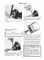
CARRIER SECTION
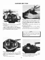
101..,.
Figure 1 46
tti..IM
Flgurt 1�4
Remo\•e pinion ma«1 �haft: with drift as tbown.
P'LKo a r.., ahop &Owele over lbe ''* to preqnt
" I> free
&om tM eae. PlJot caM in \tbe. R
e
DJO\
.. ring per
ac:rewa. T.p ring gear with a rawhid• bamftM!f to
free 1i from the e..t.t Remove cue and ring gear
from ,.
..
1 .
the rin3 .-h from being al<Ud. aliA<
NOTE
whenever the. rlng g\lAr
are re-mo\'ed they a_re t.o btt rep1oc.od
with new onea.
1t is reocommended tha'
t(T(I"'A'f
Figure 147
To remO\'f! sklc geart and pinion mate gears,
rMBt.e t he side gem. This will allow the pmaon
rruu.e ge:u'$ to wrn to thCJ OJ
>ening or the case.
nlso the spherical
Remove pinion mu� gt.'fU'8
wa!ihert beh.il\d the genr•. Lift out side gears and
l.hrust "''asher!l. ln.tl)«i all pcu'ta. including Lhe
machined 5Utfact>8 of tho <:ale kseiJ. If excessive
wear is visible on 111 part�. It iJJ suggested t.haa. the
tt�mp.Je.te differentiiJ �mbly be replaoeod. lf any
or.eofthe gears are-to � replM'«<. TilEY AR£ TO
BE REPL�CED AS A S£T
nnd
Agurt 1'5
ltepllce caN in \iw-
,.,..,,,..
and drh-e out tock pi
n ,.:hlch
MCW'H the pinion mate shaft� Ute a
�hown.
tma
D drift •�
NOTE
T'he aemi·Roat shalt ridiog bearing deslgn h11
lock pin that Is re.mo\•ed with a wr�nch. Tho
pm.ion ma� lhflf\. ls or tbe tlip fit design and
a
an be rtmo..-ed by h.snd.
NOTE
A)!Jf" shtlft.8 whtch ruqulrc end phty adjust
mf'nt.s have a tlpuc.:er block In the diffarentittl
case. The Sl>acer 1>\ock controls lh.o end thrust
or the axle shaft. U the ends of the sp,aeer
block are worn, I\ Ia &O be replaced duri ng
assembly. Spacer block mu.K not� \l&ed with
baU or unitized whH.I beorinllt.
CARRIER SECTION
NOTE
On the
lf'lline eod of Lhe pinion, there �
bearing P'Oioocl lhU... These ohims may •ldl
to the plnfon or bMring or even ran ouc.. Th�
shUn, are \0 be coiJeded and kept �btr
since they will be used Later in �mbly, 'T'iy
not tO mmilatc ahtms. II shims are mutilated,
repltace wtth new ones. Shlms are tJvailable In
lhickne.... or .oro·· . . 0()0", .010". and .030",
lmm .08, .13 . .25, nnd .761.
Figure141
Twa
nose
rt'mo
,
..
,....,.
of carrier irl a horfiOI'IC&J posilicm,
nuc and washer.
pinioa nut� Hold end ycke
lOOI. &a abown. and remove pinion
Tool: IC-3281 IIDiding WNnc:h.
01'
Range •;lh
sot••"
Figure 151
Pllll ""' pml<>o- wtlh pull..- .. shown. m......s
seo1. R£PL\C£ \\'!Til NEW O�'E AT TIM"£ Of
A.SS.DtBLY. R�.. bearing COI'le and OU4er oil
-
Flgut't Ul
slinget".
Tool: /().J31 S!idt Hamm-er.
�•u.t
R8nove end yoke of flange Wh tool8u 1hown. 1 r
ttl\d yoke or flange sbows wear in the fl!'ea of the
tt
..l contact. it .should be replaced.
Tools: NC--3281 Holding Wrench, .tC-402 Yoke
Rcmc)\+er.
F igure 150
Figure 152
'fum nO!Ie of clUTier down. Remo,,e
,,,,.,to
outer pinion
bearing cup. Loc:1te drivt!r on back edge of cup:
dri\'8 cup mn of clUTior. Caution: Do not nk:lt otmle.r
ft4.'mOn pinion by �pping with a rawhide
hammt!r. Catch the pinion with your band to
pm-'tnt rt. from falling 1.0 the ground and being
damog<d.
tOtfotU
bore.
Tool>: ID-168 Cup Ro.,..n. IC-4171 Handle.
37
CARRIER SECTION
Figure 1 53
NOTE
The fro nt and rear tarrier- sect i on
m ay ''ary in
pini
o n bore dt�pth duo 1.0 the I )O' sibility of �he
n eed for either t1 baf. Rc or sling
er or both.
The baffle te rv
flt \
he tiND4! pu.tp015e ..., • dun. t.o
plnkm: �· .,. m
aintaintod with
�
•
tha&.lht
lubriea
nt
.
The
slinger
t.he purJ:I08e of assisting the
luhe t..o now up through t.hQ oil thanncls to Jubricat..e
\he pinion beotlngt�. If used, 11'1-ey •re part o( the
plnion setting t(ljustment. In rtgure J53 we show
1he four different opdons..
8erve&
,.,..,,.
Flgurt 155
Rcmo,·c pimoo bo•rlng with too!J •• shown.
Tooltt: IDD-914-P l:tn!.ss,
Ring, IC-2'93-.37 Adpcucn.
NDU-914·9
Adapt.er
NOTE
Roth b.arne and tlinj'J�r are p&r\ or Lhe pmion
odjuament shim• o.nd are to be kept. intact for
tl.sMml•ly.
ASSEMBLY
On •11 front driving ox.les there art axle shaft oil
into \ho tube endsof tho carrier.
�e11.l!l prossed
Figure 154
Remo,·e
thowo-n.
t.h•
1.nner
bearina
cup with wols as
Toots: IC-4111 Handle. ID·H>2 Cup Removt!1'.
N OTE
Shims are lorated bet.-.·een the bearing' C\11)
.net eardtr bortt aod ma1 abo inelude an oD
baffle. Ifthimt aDd bt.lfiN are bent or nkbd.
they sboukl be replaced M Lime of a.s!M.".mbly.
Wire and � t(lftet.her and mcasur(l \lath. Jr
sr.ack has 1.0 be replaced, rcpt&ee wilh �tamo
tkkneu.
h
Flgurt L/0 C.rr1tr Seal 156
t01..1..
A! thown in figuro 11�6. t.hi.s de��lgn eonsiu of
the Integral seal Cuntt) whereby the &oeal and guide
axe 4:ombined. lOne teal for each skltl.
CARRIER SECTION
"
"
' '•
ure 15
9
Fi g
157
Atttmble inner uJe shaft ...S.
anemble eeals use tools • ahown.
Figure
,...,...,
end .cuktet. To
Tool: 11>-195 Installer.
U.se a drift \0 ine
l up the taoaes 'With those ol&he
d.i.fftoreadal eate.
�mbJe pinion ma� thaft, drive oa abaft. to
Sf wre todt pin hole of the abaft U
lined up with the lock pln hole of the ca9e.
remoo.-e drift.
W'hen assembling the seala. mako lUre they are
positionOO straight t.nd do ooc got oodted. Tum
forclng I!ICroW unli.l It stops: .eeelt wUI then be
poeltionod. GrcMet llps of scel.s.
F�ure 158
PI�«� dJrrerential
101••$t
cue in vbe .., ahown. Apply
g�Mtl:t.o new sidegear thrust lll'&lhtl'l and 10 hubs
aod t.hruJ( face or lhe new aide ,..._ A.Yemble
bo<h •ide ...... Apply grHM 10 \ho DOW •pberico)
..,..,.,. tnd \he new pinion Dlol&e,..,.. AUI!mble
n�· plnton mate gears atld waaben.
Aft eaty way co as9embt. tho •Ide �'* And
pinion mste gears is ;o ba,·e liD peru lubrk:tl�
before auembly.
AJtemble bot.b aide gears Md thruM wtshe-rt,
hold them in place wi
t h h�md. then 188emble the
pinion mat.e gears and w�tshcrs to hokl thQ $ide
gean in plnco.
ltot.atc t.be !ride. geart untU Lhe holet or the
wo.shcn andpinion gears line up wiLh the holes of
the eaae, lf the gears eannoL be roca\ed by hand.
ln•all one of the a.xie shafts iDLo the tide gear
spline a.nd wte• pi;le w1enchto &.;.tm the thafl.
,.,...,to
Figure 160
Assembl• l()("lt pin. Peen metalofease over pin to
loclt in place.
NOTE
The 3ttnJ·Doel. th.aft ridlnlt bearing design
u&efJ a loek rln LhM it as�mbled with thee uM
oro wrench. Uee kick pin and assemble fing�r
tight only, 1'bl.e J)l"()(edure is n�r y t.o
pre\•tmL differential aide gean� and diUtlrendal
pinion male gual'1 from rotating in t.bc Cl�
and droppin& out when t�ervking t.be carrier
se.uion. A new lodt pin will be iDl!talled aJter
essembtina the .sle man..
CARRI ER SECTION
Flgur• tl1
..... ..
,
Be sure ftut.ce raee of the <:ate is free of nidra or
burn. Aa.emble ring par co cue. Line up holM of
tbe ring get.r wkh thole of !he eue. UN new rl.ng
geu terewa. Draw up �s akern1tely and
evcnly. Torque rtns gear -'Crews to 100.120 L
b
. • .,
(JllG-163 N·m).
Assemble differential caM lnt.O carrier Oess
pitUoft). Mount dial lndiclcor wh.h • magnetic baM
as shown. Locate tip or lndlctc.or on flat. surftoe of
one of therio.g gear acrew IJ)Xn faeea. Marl! loct.tion
wit.h a piece of chalk. Foree dlrferentJIII assembly lUI
rar as possible in the dlrootJon 1.0\\'ll.rds tho
indicator. With torce st.lll opplled, �t lndJc�nor at
zero (0).
Tool: #0-128 lndkator Set.
N OTE
rn.l indica&oraboWd M
"
.. 1 minimum oavel of
.200" 16.08 mm).
Figure t&2
lVI
..,..
Figure 1 64
Foree the diffl'!n.'lltlai ••M'mbly at far as it will go
in the (lpposite dirtctlon. Ropeet thE>..te steps un\11
you hth'e obtn.inod the wn• reading. Record l.be
reading of tho lndica.lor. 'rhiJ will be th� lOUP.I
amount of .shims ruquired (lou p,-e!Qadl and will be
ealculated lat.cr during ueembly. After m$kingaure
the readin.p •.re corroct. r•move indicator and
d
i fferential •.!sembly from housing. DO NOT
REMOVE MAST&R BEARISGS I'Rmi DIFFER·
£.','TIALCAS£ AT THIS TIME.
•O�t··•a
lnsta11 m••ter differendal bearinp onto eate.
Remove all nlth, buns. din, ec.c:., from hubt to
aUow mauor bearings to rotate freely.
Tool: ID-117 Muter Differential Bearinp.
40
CARRIER SECTION
removing shims, the. mounting
dista.nc::e of lhe
pinion is n
i creased to 3.12
8" (79.45 mm), which is
just what a +S (m+8) indicates. Or If a pinkm is
et.c;hed -3 lm·S•. we would wao\ to 1.\dd .003" (.08
rruJ\l more shims Lban woul d be- required if the
plninn were etched "0". By adding .003" 1.08 mm)
shims, the mounting distance of the pinion was
decreued to 3.122'' (79.30 mm) wbieh Is just what
a -3 lm-8) indicated.
If the old ring and pinion $C\ Is to be l'eused,
measure the old shim puck and build a new shim
pack lo this same dimcru�ion. llll baffle 'l
L used in
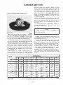
VIEW OF RING AND PINION SeT
the axle assembly. it i s considered as part of the
shim pack.
To change tbo pinion t'ld,iustmenta, shims are
available in t.hickoosso& or .003". .005". and .010''
(mm .08 . .13. ond .261.
NOTe
If baffie or slinger is bent
should be replaced.
Figure 165
Ring goons ttnd pinions t��re Sl.ll)pUed in :matcl'led
sets only. Matching nurobers on both thepinion and
ring gear aro tt.<:hcd for \'etlfieation. lf B new gear
set is bei.ng ..ued, varlfy the numbers of each pinion
and ring gcttr before pr1;1CE!eding w
i
t h assembty.
The oom.i.ottl distance from the centerue
ti
of the
ring gear t.o 1.be end of the pinion for the model 60
(front. l\nd rearl axle is 3.125" (19.37 mmi.
On the buu.on end of each pinion, t.bere is etcbed
" plu.s (+) number, a minus (-) number, or a zero
i
t.he best running
(0) �umber �A•hich ndica\es
pOsiuon for each particulargear set. Th.is dimen&on
ls oonti'()Ued by the shimming behind the inoer
pinion bearing cup.
For example
ll a pinion is etched a plus +3
lm +8l. this pinion would require .003'' (.08 mm)
1e� shims than a pinion etched "0", This meM!f by
•
Ill " Pilin Mwlll
t
Mtrb-a
-·
_,
_,
-I
•
+I
+!
+l
+'
+'
-+0
.
008
+0 001
-tO.IX6
+O.
<Xb
ot
•
+t
.... ..,
+• 002
X
J
II
+O
•
tl
tO OOI
+....
+0.<0
.. ...
t<Ol3
t<OOZ
+O
J
))
I
0
-CUll
+I
t OCC<
+0.
<0
+0.00t
-+O.cm
+0.0)2
+0.0:1
•
- 0�1
-o.oJl
+I
+-.
0005
+'"
'
'
+O,!m
+0,
001
+""''
0
_..,,
- 0.002
-o.OOJ
.
Ol'
+O
+O.o»
+0 001
+ 0. 001
0
- 0. 001
..,
-ODll
-O.OOtl
-I
H lll!l
+O,®
+0.001
0
-0.001
- 0.001
-0.013
-0.00'
-0.00'1
,
+0002
+CQ)\
0
-0
, 001
- 0002
-0.001
-OJ))t
-o.oos
-0.�
-I
+4001
0
-00:1
- OW
..,
-o.�
_..,.
-o.ca.
-·
0
- o.o
1o-
-0 001
- O lll!l
. ..
-O.IX6
- 0.00 1
•
_
•
mutilated, It
Measure eech sblm scp�,trately with a micrometer
and lldd wsether to �:eet t(JC.al shim pack thickness
from the origil)&.l buil d up.
If I) new gear set is being used. notice the (+t or
H etching o n both the old and new pinion and
adjust the thic-kness of the new shim pat* to
compensate for the difference of these two flg'W'es.
For e.xarnple
If t.h e o l d pinion r�& ( + l 2
(m +6) and t.he new pinion is H 2 (m-6). udd .004-"
(.10 mml shims to the orginal shim pa<:k.
The abc.n·e proceduf'ft al80 apply t o pinion
adjustment on 'he front a.xt.c wb.lch includes the oil
tinger
s
betwc(•o Lbc lnner btarin.g cone and pinion,
and bafOc bc,woon t.he inne r bearing cup and
carrier.
•
ON l'illi••
or
Pinion Setting Chan
_
_
..,.
(English
41
_
_
U.S. Standard).
,.,
_
-• o:o
CARRI ER SECTION
........
M•W.t
•10
.... .... ... ms:
- 10
+.20
�
..
..
·10
.
...
•.OJ
+,OJ
0
...o,
0
-. 03
0
-·
...
-·
+,U
+.15
+,n
.. .10
..
+,18
+
.15
+. 1)
•.10
+.08
+.OS
+>
+.IJ
+.13
+.to
•.oa
...05
+.03
0
.,
+.ll
•. to
+.08
-+,0!1
+.Ol
0
• . Ol
• •
0
+,1
0
...08
....
.. .03
0
- .0 3
- , 0,
-.08
-. 10
,
.. ..
•. OS
._.,
-.03
....
..
-.10
-. u
_,
+.0,
-.03
__.,
..
..
•,10
-.ll
-.15
..
._ .,
to
- . ll
-.u
-.11
- . 11
- . 20
_
·1
0
Figure
0
0
0
.,
_ _
.,
__
187
....
0
-.
OJ
.,
__
..
. .
.
...
.. .
- .u
-.to
..os
..
. ...
.
os
...o,
- .
08
Pinion Stttlng Chart Metric
11 metrlc u.lled pinJon will be etched Ex-p. (m+61. Use these charts u.s a gui
d eline to teL pinion.
l\ake sure thaL aD cat1"i« borea are free
nicks.
dirt
or any ot.her contamination.
&om all
,..,.,..
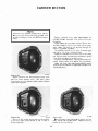
Figure 1 e8
View of ll11flter pinion block. pinion b.olght bk>ck,
scoot.er g�Jt&, cross pin, tllld muter bearing di8CI.
�OTE
C1'018 arbor, muter beiU"ing �.
d
and ecoot.er
gage can be uaed on bothModel 60 and Model
;o ulea.
Figure 169
ttt•'"
f'tace muter pinion bkd Into lhe pin)on bore of
the carrier a.s thown.
Tool 11).120 M ....,, Pillloa Rlodc.
CARRI ER SECTION
Figure 172
••trt
l'loc. - - on ....U - of J)Won height
block. Apply p.-... will> r.....,.. � ..,.. tho
gage Us flat oo the pinkln bloc:k, •hUe pt"Qsure il
app&d tel indicator at. zero "0''.
Tool: #"0�116 $cooler Gage.
1011-1M
170
Place t.rtx>r dl� lsm•U diamec.ert) and arbor in�
ct'Oltl boree or eanier as shown.
Figure
Tool•: ID-116-2 Ma� Discs. II).ll&.-3
Atbcw.
Figure 173
,.,.,1,,
Slide eoootor gtt3c ()V(l;r arbor. As g11.ge $tldet
over top of •rbor, iL w111 travel in • clockwln
directioo. When lndJcator Is on cen�r of arbor (on
top) it wilJ ttop ,,.vemna Ina clockwite dke'(don. If
inM:ator
d
.Ut\1 10 t.ravel in a c:ounter-dockwi.H
irection,
d
lhis mNnl you htve passed the center
(wpl oftho arbo<. Re<Ord onl)o tho� "ben tho
tndieetor itat the hlabetl point..
This reacUntc indkltet the amount of 9himt
necessary w, obt.ain t.ht shim padc:, plU5 (+) or
minm H the etchlnc on 'he button end of the
pinion.
U the
l&�•m
�Iaure 171
Pl.u pinion height. block oo lOp ofmaster ptnion
bLock and a.pinst arbor*' shown.
Tool: ID-111>-1 Plnloo Helgbt Block.
et.c:hing It 1.ero (0). the shim pack wiU
remain unchangoc:l.
For exarnple: If tho plniQn iiJ etched +3 lm+8),
t.h.i.s pinion woukl fiKl\llre ,003'' 1.08 mml less shims
than a pinion etched uro 101.
llthe pinioo IJ etched o3 lm·8•. this v.'OOld require
.ooa·· 1.08 mm) mort thim.s than a pinion etched
z:ero «O).
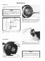
CARRIER SECTION
,�,,..
Figure 176
Fl
gurt
174
Mcuure HCh
and add
"'• "
•
shim .sep8J"'Uely with a miC'rometcr
t.oct"therto get toW shim pack lhkkncsa. If
Asoemble the ..,.., plnloo bearing t1IP imo
earrier as :sbown. make lUre cup lt te#ted.
Tools: fC..I203Cup lntealltr. rC-1111 Handle.
,_me I• required it s
i to be included ln tht thlm
Jf •linger is used between the inne:r belling
ccme and thrust face or pinion, the slinger It 111leo to
1Je mcasun.'(i And included as part of the I.OLa�l ahlm
pd
J)M;k.
1e1t.m
Figure 1n
Assemble IMer bearing con� •and aUngur if usedI
on pinion.
Drive be.lirlng on !lhn.ft unLil it s
i
completely seated.
Tool:
•o••"•
Figure 175
Ploce the rtq:ul� amount. of shim� (and bafno If
u!ledl in 1.1\e Inner bearing bore: drive tho Inner
bearing c:up Into the carrier. Make sure c:up iJ
seated.
Tooloo 10-1 1 1 Cup Installer. IC-<171 Handlt.
iC-3095-A Be11rh�.g Installer.
•o••n•
Figure 178
Assemble pinion inLO curler. Auemble outer
pinioa bearing a>ne. t��nd sUncer if Wit'<!) and end
yoke onw pinion spJine.
CARRIER SECTION
NOTE
Do not assemble preload shims
'Jeal at this time.
or
pinion oil
Usc yoke in8lal1er ttS shown t.() assemble end yoke
onto spUmt of pinion.
'tools: fC·3il8 lnstaUer. IC�3281 Holder.
Figure 180
Place rubor and discs (small dhlmOte.r dii:ltS for
Mode) 60 axlo and llltgc diameWf u&ed on Model 70
axle) into cros.s bore of ctuTier. Place pin
ion height
block on butlon end of pinion. Set. dial lndlcl\t.or on
small s<cp or hcigh' bloc.k lbJilh •�P or block is used
for �Jodel 70 axle.) Set dia1 indicator at zero "0''.
Slide seoocer gage �CtOS$ or O\'et $rbor.
lndlcator will read a ptu.!'l (+) l)r minu.'l H at its
highe-.st pobn. depending on the etching of the
pinion.
NOTE
l.atf:f" model pi_nion height biQCks are designed
tott-nt
Figure 179
Assemble washer and pinion nut. Torque nut
until it requ)r(!s 10 Lb. ln. U.l3 N·ml to rotate the
pinion. Rotate pinion several time.s before checking
piNon po$iUcm. This 1.$ to seat the bearings and
assure " more accurate reading pinion depth
sel,dt�g.
for each ind.ividual modeJ axle. Therefore . it s
i
()()�ible w have a height block t.hat does no&
ha\·e a step as pkt.ured and described.
Tool: IC-193 ln.·Lb. Torque W-rench.
NOTE
indicator reading wllh.in .002 (.05 nun) of
etctllog Us coruddered acooptl\ble. tr pinion
pol>ition i8 found to be within speeincatJons
e<>nti.nuc with build up. U pinion position is not
wl,in
h spcclt.ions
liea
change s.him pack thlek·
neS* under inner bearing cup.
NOTE
'l'ha reascm for � a.ssembling p-reload shims
and n�w pinion seal, at this t.ime. is due to the
po$.41ibilit.y of ba\•ing to adjust pinionpreload or
pinion adjustment.. lt would be nee�)' to
again remove the seal and. as mentioned.
whenever seals are removed. th6y fi..OO' to be
replaced with new ones. due to poS8£ble
damage.
Remove pinion nut, washer, end yoke, slinger,
and bearing cone. Assemble preload shims (which
were removed during isassembly)
d
onto pinion.
Assemble bearing cone. and .s1ingur.
4G
CARRI ER SECTION
t01..tn
Figure 183
Using an ln. Lb. torque wrv..nch as sh�·n. rotate
pinion. Torque tO rotttt.e pinion should read between
20-40 Lb. ln. (2.26-4.53 N·m•. To increase preload.
remove shim.o1: to decrease proloa.d add shims.
tot..,"
Figure 181
Apply ag
U ht coat of hypoid lubricant on the lip of
pinlon seal Md nssembiE> into carrier.
Tools: 10·163 (Nutional) Seal Inst.a.Jler, 11).164
IChiettgo Rawhide) Seal lnstaller. IC·417l Handle.
t o, ..
Figure
182
, _.
Figure 1 84 l /0 Carrier
Tbe UhJ,S*rl\\km tn figure 184 shows the arrow in
the pinion pointing in twu directions. The direction
pointing tcHo;•ard.; t.bc cnd yoke indicates that by
removing pinion pos-Ition :sb.im.s, '-he distance frc)tn
the centerline or the l\lle to pinion button is
n
i creased g
iving a plus l"('�ding. Tho preload shim
pack does not effect tho pinion d$pth setting.
Arrows on the rina gear ilJu"rtue l.he method to
increase or decrease baekiMh and dif
f trcntial
bNring preload.
ttuo.,.,
As!iemble end yokP,, washer, Md now pinion nut.
Torque not to 240·300 Lb. ft. (325·406 N·mt.
Tools: ;·C-,.053 Torque Wrencll, .te-.3281 Yoke
Holder.
46
CARRIER SECTION
;iio-�
ASSEMBLY OF DIFFERENTIAL
1'1-. df
d....
o
tial ....
mblr
.
!will>
ln10 housing. Differential master
JtOl be 8.!8embled to ease.
pl
nloo u...l.Jiecl
beltrinp abou.ld
.,....,
Fi
gure 187
Assemble the requlred amount. of $him ontO hub
(ring goarmdol ., doWrmlaod In figure 156. Ploc:o
bearing cone on hub or ate. Ute bearin8 lnsulier
to !INt bearing amc ._, .llbown.
,o,.....
Fi ure 185
g
up dial indica�• u shown. Be .1uro to locat.e
dial Indicator on $8.Dle location ., m1ril6d In rlriUre
i
gear inio mef.h wh.h Lhe pinion.
ISS. .�oree rns:
Rook ring 10 a11ow Lhe teeth or the gtlll"' to mesh.
Wilh force .UU applied to Ute differential ca.. aet
Sd
lndicM.or as. zero ··o...
Tool: #D-128 Jocticacor.
Tools: #C-4062-A Installer. IC-4171 Handle.
tDD-914-42 Buuon.
AM!cmblc Lhe: roJN.
t
nln or the \OW $him pRek
g
which wftS det.ennln(!(l tn fiu
gre 164 onthe opposhe
side of the dlffe1'6nllal eaac. Add an additionRI
.015'' (,38 mml of thlmt on tis
h side to compensate
for dlfferP
n dal bearl'VJ preload. Assemble diffE!'I'en·
tiaJ bearll\l,l' utlna: the same tools as sbo"'-n in figuTe
187.
lo figu"' 16< (looa pinioo) a IGial o! .107"
indicator ....U,. .... .......
lo figuro 156 !will> pmloo) a IGial o! .OM"
.-u m:orded. This lea\W a
bahmee .062" of llhlmt foe lbe � s� and
adds up to the .10'1" whlc.h wu first recorded.
Add an addi!.ional .Ol&" thUm on the OPJ'lO('ite
side for boarins prtload and backlS..!Jh.
indic:aLor �
Ring c .,.. S id• . ow· ( 1.<0 m
m l
Oppo&it.e Side . 062' ' 1 1.3
2 mm)
Qup<�site Side Prel011d
Flgurt186
.Ol6 ' ' ( .88 mml
t01Jot•
r()tw l.h(! dlfrcrent.i&.l case (ring «eer) •.,.., from
Lhe J)lnlon gear lO obtain an lndh:etor rt.'tlding.
h
llepctlt u.otn �he same reading ls obtalnod tuc
Llmtt. Th.lt reading will be the nece.uary amounL or
5hl.mt required between the d:ir!ercntJal ca&e tnd
diffeNnc.i.al bearings on the ring gear llde. Rei'OO\•e
Snd..lc:ator and differential caH from the carrier.
RtmO\>e. muter bearings &om difftrenWII C&te.
101t.111
Figure 188
install aprud« and lndlc.at.or to carr ieru aho••n.
Do aot sj)ft6d. canitr O\'er .015.. C.38 m.ml. Remove
irutieat«.
CARRIER SECTION
Figure 191
Cheek ring gear and pinion bacldn.sh in three
equa.Uy spaced point-S with din) indicator as &bown.
Backlash tolerMoo is .004" (mm 10.. 23) to .009"
and cannot vtlry more thnn .002" lmm .05) bot:"'--een
J)()ints ehecll.cd.
High backlash is corrected by moving th& ring
gear closer to the J)inkm.
Low backlash is corrected by rtl()vlng ring gear
.
IO'Ito••
Figure 189
Alssambledifferential bearing cups to differential
bearing <:ones,
lnstall dlfferenUtU asst.mbly into carrier.
Use D ruwhkle hammer to seal. differential
;;tSsembly into cross bore of carrier. Oare shouJd be
w.ken to twoid nicking tho tcutb of l.he ring gear and
pinion durlng assembly. Remo••e apreade.r.
.
away from lhe pinion.
These oorrecUon.'l are made by switching sh.lms
from ooe side of t.he differential case to the Other.
NOTE
H �r\•iclng t.he .!lemi-Ooa\ shaft. riding bearing
de&ign unit, refer to the mnoual seWon for
that unit. After lnst:ru.Uog tutle .!!halts. a n ew
loclt pin l! ins1.aUcd.
,01..1110
Figure 190
In.st.all bearing caps. .Mnko sure the letters
$1M'Iped on l.he C(l;_l)S COfrtt�pond wi
t h those on the
carrier$. Torque bearing et\p !sCrew$ to 8()..90 Lb. Fl.
008-122 N·m).
Tool: IC-.524-A Torque Wrench.
Flgur• 192
l01t-11n
lnstall new cover gasket and install oover phu.�.
Torque screws to 30-40 l.h. Ft. t4l...S4 N·ml.
'rool: tc;...;
2 ·A
<1 1'orq_ue Wrench.
48
CARRIER SECTION
N OTE
There a.re two different design oovcr plotos.
One cover is of the flat mounUng �urfru:::6. nnd
the other design is of tbe rib-5 be�woon $C.r4)w
&alant. malb"illl
must meet specifications
of
ASTM3. GE303. A19. 83'1. 1>16. E36, Zl. Z2. and
Z3 Sl!
a lant..
Apply staler t.o cover plate surface. Ensure that
the .sealer boo:d is laid on the inside of the cover
.screw hole3. The bc<ld is not to pa$s t.hrougb the
holes.
holes or outsid& of the boles.
The bead I.to be 118" t<> 1/4" 13.18 6.35mm) high
and us· to t/4" 13.18 . 6.3$ mml wide.
A$-!Cmble 'wocover screws into cover at S o'clock
and 2 o'clock po!rltion. Use these two bolas Lo gu1du
cov€:r plate into position on the carrier.
Inst...U remah�ing$Cl'eWS. 'f'igbt..en alternntaly and
ave.nly. Torque serews to 30·40 Lbs. Ft.. (41·54 N•m•.
Allow one hour e.ure time before fiiJing �.rrier
with Lhr� proper amount of specified lubric:M1t. ttnd
vehicl
e Operadon.
•
Figure 193
J.lgure 193 shows
101,.m
t.he flat mounting surface cover
plate on Dana design axles. This OO\'er plate
requires \he use of a silicone rubber .sealer material
rather than a gasket.
Figure 194
The co..-cr
"""�·�
-�
Figure 195
'1)1"'"'
fnco of t.he C(l.rrier and the flat surface
of the over
c
plote must. be free Qf MY oil film or
foreign ml\t�rial.
I01t-lh
On cov"'r plate ofthe rib dea:lgn, a gaskeL must be
u50d. Do not usc silicone sealet-. Torque screws t.o
3().40 Lb•. Fl. 141-54 N·m}.
49
REAR AXLE SEMI-FLOAT
SHAFT RIDING BEARING DESIGN
"C"'LOCK
OIL SEAL
BEARING
• 1i8
Fleur
•
. .. u 1M n
lH
ttlf'll!'
I
l l•IOIM •·
t 2t · 34 11
'11 .
F
tg
ure181
CA
UTION
..
Flgurt 197
Axles built in modcl y� 1980 •nd modl":l year
1981 uted Jock�Ja"eW st")•lo A� Starting In model year
1982. •xle! we.-e built. uai.ng lockeerew tiyle B.
,....,
THE UJCKSCR!:WS ARE NOT INTER·
CHANGEABLE. Core ohould be exercilied"'
assure that the� repJtcement lock.screw isiden·
tical t.o Lht ont removed. 1"o identify the case
for proper tcrcw selection. measure Lhe
dist.oncc from tho oont.erline o( the cross-shaft
hole t.o the Cll!lt •urface when! the lock�"'
cnlers the C:MO• tr it measures appro.ximal�ly
1.000 iL wUJ require Jackscrew style A. 11 it
mees�res appro:dmat.eJ.r 1.312. ic. will �
lock..,.., oLylt B.
50
REAR AXLE SEMI-FLOAT
SHAFT RIDING BEARING DESIGN
Figure 1 99
•o•..�•
Remove thedifferenti.al pinion shaft loc.k$crew as
shown.
Flgure 200
1o1woo
Install lockscrew, making sure bole n
i the dif·
ferent..ial. <.Toss-shaft s
i lined up with the screw hole
i.n the differontJal case. Maka sure throod5 in dif·
ferent.ial ease and on the Joc.lu;crow aro (n>c of dirt
and oU. 'T'orque lock.screw to 1S·2b lbs. ft. (20..
34
N•ml for style B n.nd 8·J2 lbs. ft. Ul·H) N•m) for
$tyle A.
Tool: Q.S24·A Torque Wrench.
NOTE
New loctcs.crows lstyle AJ have locking type
1nt.erial on the th.reads that 9l'Cures the pin
••hen in place. Nl!\\' lockscrews (style B) have
special t.hn!ads that. secures the pin when in
place. Therefore, WHENEVER 1'HE LOCK·
SCllEW JS llEMOVED. 11' JS TO BE DIS
CARDED AND REPJ.ACED WITH A NEW
ONE. Before nstalUng
i
lockscrew. make sure
hole is free of dirt and oil.
61
WE SUPPORT
VOLUNTARY MECHANIC
CERTlFICATION
THROUGH
Dan. Corporation. Spicer Ad. Oh·lJion. fftlen•ts
tbP light. to make
without ootice or
dlanges from tUM to tlmt.
obligation. m •pte:ification-.
descripdoos.. and illustrac.iooa. and LO dWontinut
modt-ls <K 1'1!'\ise ck>Sgns
Q-'<>n• rtgardln@ ''"".,..,..,, shoWd
''"
be dl..etf'd
Spicer Axle Division
Dana CorporaLiQr\
P.O. Box 1209
J<"'ort \"rayne, Indiana <4680 I
Altention: Engineerinl( Technlcnl S<'rvlcc D<ll)l.