1
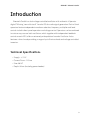
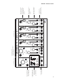
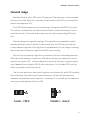
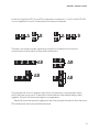
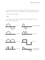
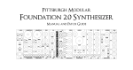
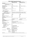
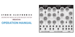
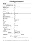
ALM-011 - ‘Akemie’s Castle’
ALM-011
‘Akemie’s Castle’
- Operation Manual (V0.1)
Introduction ............................................................................................3
Technical Specifications .......................................................................................3
Background & Caveats ............................................................................4
Core Operation .......................................................................................5
Panel Layout .........................................................................................................5
General Usage ......................................................................................................7
Patch Ideas ............................................................................................13
Limited Warranty ....................................................................................14
Support ...................................................................................................15
"2
ALM-011 - ‘Akemie’s Castle’
Introduction
‘Akemie’s Castle’ is a dual voltage controlled oscillator with authentic 4 Operator
digital FM using ‘new-old-stock’ Yamaha IC’s for audio signal generation. Each of the 4
operators feature independent waveform selection, frequency multiplier and level
control via both direct panel operation and voltage control. Operators can be combined
in various ways across both oscillators, which together with independent feedback
control on each VCO, offer an extremely wide palette of sounds. Oscillator A also
features a chord mode providing a range of up to 5 voice chords and voltage controlled
inversion.
Technical Specifications
• Supply: +/-12V
• Current Draw: ~120ma
• Size: 38 HP • Depth: 32mm (including power header)
!3
ALM-011 - ‘Akemie’s Castle’
Background & Caveats
Frequency Modulation (FM) synthesis is an audio synthesis technique where
waveforms modulate each other at audio frequencies to produce a wide array of both
harmonic and in harmonic sounds. These modulation waveforms are referred to as
‘operators’. The combination and routing of a number of operators to produce a sound
is referred to as an ‘algorithm'.
FM synthesis was made hugely popular is the mid 1980’s with the launch of the
Yamaha DX7 synthesiser. Yamaha implemented this through the use of custom digital
FM synthesis chips which were used not just across their synthesiser range but also in
gaming machines and home computers. For more information visit: http://
en.wikipedia.org/wiki/Frequency_modulation_synthesis
Akemie’s Castle uses a vintage ‘new old stock’ Yamaha YMF262 (aka OPL3) chip as
a sound source and exposes all operator parameters to both voltage and direct control.
It is able to produce multiple voice 2 or 4 operator FM based sounds from 6 algorithms
and 7 selectable waveforms. This is very similar in audio capability to the Yamaha
DX100, DX21 or TX81Z synthesisers.
Using an original chip gives a very authentic and special sound that has never been
put under direct modular control before. This allows easy, fun and painless exploration
of FM sounds that was not really possible with the heavy, menu bashing small screen
style of programming the FM synths of the 80s.
However, using an original chip imposes some limitations, some of which become
more apparent with such direct control. Expect some ‘stepiness’ and potential low level
clicks when changing certain parameters. It is only possible to modulate parameters
up to low audio rates. The chip will alias and even distort if pushed hard enough in
certain settings - care should be taken. One can quickly go from rich tonal bliss to
crushing noise. It is a beast, but one that can be tamed. Embrace and enjoy these
limitations.
!4
ALM-011 - ‘Akemie’s Castle’
Core Operation
Panel Layout
Please see next page for a panel diagram.
---
Notes:
All jacks are inputs expecting control voltages except the two VCO audio outputs
at lower left. Full frequency range output is approx. 0.05Hz to just over 6kHz
All inputs expect 0-5v except chord and V/Oct inputs which expect approx. 0-10v.
All inputs with an associated white knob have a separate attenuator (or
attenuverter). The white knob acts as an offset to which any incoming control
signals are combined with (post attenuation).
All inputs with a grey knob (i.e wave selection) act as an offset with no incoming
control signal patched. With a control signal patched they become attenuators
for the patched incoming signal.
The V/Oct, ’Inv’ and ‘Fb’ inputs have no attenuation controls.
Osc B ‘Fb’ input is normalised to the main Osc A ‘Feedback’ control - i.e with
nothing externally patched into Osc B ‘FB’ input the main Osc A Feedback level
will be used.
Beware output levels can vary dramatically depending on operator setup and if
chord more is enabled (level will increase!). Watch for distortion.
!5
Audio outputs
for each VCO
Algorithm selection.
How operators are
combined and
distributed to
each of the VCO’s
Seperate feedback
input (normalised
to Osc A feedback)
B
3
B
4
sc
B
O
ut
1 2
3 4
1
2 3
4
A
O
ut
AB
AB
Operator section
sc
A
Fb
- +
Inv
Chord
Chord
Feedback
O
V/Oct
Level
- +
Level
Mult
Multiplier
Wave
Operator - 1
Level
- +
Level
Mult
Multiplier
Wave
Level
- +
Level
Mult
Multiplier
Wave
Level
-|+
Level
Mult
Multiplier
Wave
Operator - 2 Operator - 3 Operator - 4
— AKEMIE ’S CAST L E —
1
A 3 4 B
2
Operator
Algorithm
AB
1 2 3 4 AB
1 2 A
O
1
2 3 4
Fb
V/Oct
Freq
Oscillator B Section.
Freq
Oscillator A section.
Includes frequency, feedback
and Chord controls
CV inputs with
attenuverter and
attenuator controls
Operator amplitude
level offset control.
Operator frequency
multiplier offset
control
Operator waveform
selection control.
Acts as attenuator
when external CV
patched
ALM-011 - ‘Akemie’s Castle’
!6
ALM-011 - ‘Akemie’s Castle’
General Usage
Akemie’s Castle is a dual VCO with 4 FM operators. The operators can be combined
in various ways (the ‘algorithm’ ) and then routed to each or both VCOs as to produce a
tone for the respective VCO.
Each VCO’s base frequency is set via patching a voltage into the VCO’s V/Oct input.
This value is combined with an offset set by both the course and fine knobs (i.e as to
tune the oscillator). The audio tone in then output at the corresponding VCO output
jack.
There are 6 operator algorithm settings. The algorithms are stepped through by
pressing the blue button of the left of the control panel. An LED then indicates the
current selected algorithm. Each algorithm is represented by a small diagram showing
the combination of Operators used and the VCO output routing.
With the first two operator algorithms you essentially have 2 completely separate
VCO's each with there own 2 operators. With the remaining 4 you essentially have a 4
operator duo-phonic VCO - the same algorithms and tonal config but a separate pitch
input, feedback (normalised to VCO A) and audio output. In all modes VCO A has the
ability to produce up to 5 voice chords.
The first two algorithms are simple 2 operator combinations for each VCO providing
each with either a parallel or serial type combination. In Serial the two operators
frequency modulate each other (operator 1 modulates 2), in parallel the two operators
are simply mixed together (No actual FM).
1 2 A
Serial - FM’d
1
A
2
Parallel - mixed
!7
ALM-011 - ‘Akemie’s Castle’
In the first algorithm VCO A is an FM combination of operators 1 and 2 whilst VCO B is
a mix of operators 3 and 4. In the second this setup is reversed.
3
1 2 A
B
4
1
A 3 4 B
2
The next 4 are more complex algorithms using all four operators and various
combinations of both serial and parallel connections.
1 2 3 4 AB
1
2 3 4
AB
1 2
3 4
1
2 3
4
AB
AB
For example the first of 4 operator algorithms, all operators modulate each other,
whilst the next two group of 2 operators modulate each other before being mixed
together. The last two are more irregular arrangements.
Generally the more operators generally the more complex the sound. Also the more
FM connections the more complex the sound.
!8
ALM-011 - ‘Akemie’s Castle’
The right half of the control panel provides controls and inputs for each of the the 4
operators. Each operator section is numbered as to match the algorithm diagrams.
Each Operator has 3 Settings;
Wave
The selected waveform used by the operator. There are 8 different waveforms;
Graphically represented they are;
1. Sine
5. Alternating (even) Sine
2. Half-Sine
6. ‘Camel’ Sine
3. ‘Abs’ Sine
7. Square
4. Pulse Sine
8. logarithmic sawtooth
/Derived Square
!9
ALM-011 - ‘Akemie’s Castle’
Multiplier
The multiplication ratio applied to the V/Oct frequency as to then apply to carrier
and modulation frequencies within the selected algorithm
Ranges increasingly from 1 to 15.
Level
The amplitude level of the operator. Has a range of 0 to 63. Note it is normal in that;
- Sweeping the level in some situations can cause low audible clicks (this is most
noticeable in last 25% and in FM like setups).
- Very low levels will not always completely mute a operator - there can be some
bleed.
Further to operator and frequency control, the output sound can be further
controlled by both feedback and chords.
Feedback
As mentioned previously each VCO has a feedback setting which controls by how
much (0-7 range) the initial operator in the current (per VCO) algorithm self modulates.
Feedback can be used to produce an increasingly ‘coarser’ sound - beware however
it is dependent on the operator setup as to how much effect feedback can have. Note
feedback can also effect tuning.
By default the feedback setting of VCO A is shared across to VCO B. By patching into
VCO B’s ‘Fb’ jack this connection is broken and VCO B feedback can be independently
controlled.
!10
ALM-011 - ‘Akemie’s Castle’
Chords
VCO A is able to produce up to 5 voice chords which the V/Oct input providing the
root frequency of a selected to chord.
The type of Chord is selected by the ‘Chord’ control offset and/or a control voltage at
the associated Chord input. The chord selection with number of voices are as follows;
1. Fifth (2)
2. 1 Octave (2)
3. 2 Octave (3)
4. 3 Octave (4)
5. Major (3)
6. Minor (3)
7. Suspended (3)
8. Augmented (3)
9. Diminished (3)
10.Dominant 7th (4)
11. Major 7th (4)
12. Minor 7th (4)
13. Maj/Dominant 9th (5)
14. Detuned (3)
15. Detuned (4)
16. Detuned (5)
!11
ALM-011 - ‘Akemie’s Castle’
Further to this Chords may be inverted by applying a voltage to the Chord ‘Inv’ input.
Increasing the voltage increases the amount of inversion.
Multiple voice chords can increase levels quite dramatically and cause distortion.
Be aware of operator level settings - the final one(s) may need lowering when chords
mode is enabled.
There are a wide array of parameters that can be changed leading to an almost
endless palette of sounds to be discovered. However care should be taken it can be
very easy to go from tonal bliss to hissing noise. Sounds can become inharmonic and
untuned.
!12
ALM-011 - ‘Akemie’s Castle’
Patch Ideas
Simple Sine Waves
Useful for module tuning and calibration (also see trimmers on rear to adjust
tracking), the module can simple sine waves with either initial algorithm selected and
all chord, feedback, wave and multiplier controls all set fully CCW. Level control set
dependant on selected Algorithm.
Melodic Chord inversions
With a chord activated try patching a slow moving LFO into the inversion input for
some pseudo sequenced melodies. Adding further modulation to other inputs will
further excite the sequence.
Drum hits
With a 4 operator algorithm selected and the chord control set full CW , try patching
triggered envelopes with a very short attack and quick releases into Oscillator A V/Oct
input. Also mult this envelope also in a VCA combining with Oscillator A output. Further
mult into other Akemie inputs. Try adjusting a the feedback. A huge range of drum
sounds can be discovered.
More to come soon!
!13
ALM-011 - ‘Akemie’s Castle’
Limited Warranty
From the date of manufacture this device is guaranteed for a period of 2 years
against any manufacturing or material defects. Any such defects will be repaired or
replaced at the discretion of ALM. This does not apply to;
• Physical damage arising for mistreating (i,e dropping, submerging etc).
• Damage caused by incorrect power connections.
• Overexposure to heat or direct sunlight.
• Damage caused by inappropriate or mis-use.
• Use of incorrect or non official firmware
No responsibility is implied or accepted for harm to person or apparatus caused
through operation of this product.
By using this product you agree to these terms.
!14
ALM-011 - ‘Akemie’s Castle’
Support
For the latest news, additional info, downloads and firmware updates please visit
the ALM website at http://busycircuits.com and follow @busycircuits on twitter.
Please send any questions or comments to [email protected]
!15