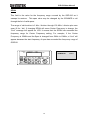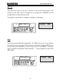
1
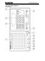
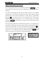
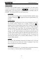
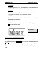
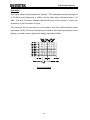
Spectrum Analyzer
GSP-810
USER MANUAL
GW INSTEK PART NO. 82SP-81000MF1
ISO-9001 & ISO-14001 CERTIFIED MANUFACTURER
This manual contains proprietary information, which is protected by
copyrights. All rights are reserved. No part of this manual may be
photocopied, reproduced or translated to another language without
prior written consent of Good Will company.
The information in this manual was correct at the time of printing.
However, Good Will continues to improve products and reserves the
rights to change specification, equipment, and maintenance
procedures at any time without notice.
Windows is a registered trademark of Microsoft Corporation in the United States and other countries.
Good Will Instrument Co., Ltd.
No. 7-1, Jhongsing Rd., Tucheng City, Taipei County 236, Taiwan.
i
GSP-810 User Manual
Table of Contents
1.0 GENERAL DESCRIPTION AND FEATURES...............................................................................2
2.0 USAGE PRECAUTIONS AND RECOMMENDATIONS ...............................................................3
3.0 PANEL DESCRIPTIONS ...............................................................................................................7
4.0 SETUP AND USE ........................................................................................................................11
5.0 QUICK USE INDEX .....................................................................................................................27
6.0 SPECIFICATIONS .......................................................................................................................28
APPENDIX 1 - REMOTE OPERATION (STANDARD AND OPTION) .............................................32
Due to continuous improvements in the GSP-810 Spectrum Analyzer, information
contained in this Manual is subject to change without notice.
Contact GW, for revisions and corrections.
1
GSP-810 User Manual
Declaration of Conformity
We
GOOD WILL INSTRUMENT CO., LTD.
No. 7-1, Jhongsing Rd, Tucheng City, Taipei County 236. Taiwan.
GOOD WILL INSTRUMENT (SUZHOU) CO., LTD.
No. 69 Lushan Road, Suzhou New District Jiangsu, China.
declare that the below mentioned product
Type of Product: Spectrum Analyzer
Model Number : GSP-810
is herewith confirmed to comply with the requirements set out in the Council
Directive on the Approximation of the Law of Member States relating to
Electromagnetic Compatibility (2004/108/EC) and Low Voltage Equipment
Directive (73/23/EEC & 93/68/EEC).
For the evaluation regarding the Electromagnetic Compatibility and Low Voltage
Equipment Directive, the following standards were applied:
◎ EMC
EN 61326-1 :
EN 61326-2-1:
Electrical equipment for measurement, control and laboratory use-
EMC requirements (2006)
Conducted & Radiated Emission
Electrostatic Discharge
CISPR 11: 2003+A1: 2004 +A2: 2006
IEC 1000-4-2: 2001
Current Harmonics
Radiated Immunity
EN 61000-3-2: 2006
IEC 1000-4-3: 2006+A1: 2007
Voltage Fluctuations
Electrical Fast Transients
EN 61000-3-3:1995+A1:2001+A2:2005
IEC 1000-4-4: 2004+Corr.1: 2006+Corr.2:
2007
Surge Immunity
====================
IEC 1000-4-5: 2005
Conducted Susceptibility
====================
IEC 61000-4-6: 2003+A1: 2004+A2: 2006
Power Frequency Magnetic field
====================
IEC 61000-4-8: 1993+A1: 2001
Voltage Dip/Interruption
====================
IEC 61000-4-11: 2004
Low Voltage Equipment Directive 73/23/EEC & amended by 93/68/EEC
Safety Requirements
IEC/EN 61010-1: 2001
2
GSP-810 User Manual
1.0 General Description and Features
The GSP-810 is designed for minimal set-up and adjustment. The user interface
allows fast and accurate measurements. The fully synthesized design of the GSP810 permits stable operation down to 2 kHz / division.
2.0 Usage Precautions and Recommendations
The following precautions are recommended to insure your safety and to provide the
best condition of the GSP-810.
Safety Terms and Symbols
These terms may appear in this manual or on the product:
WARNING: Warning statements identify condition or practices that could
result in injury or loss of life.
CAUTION: Caution statements identify conditions or practices that could result
in damage to this product or other property.
The following symbols may appear in this manual or on the product:
DANGER
ATTENTION
High Voltage refer to Manual
Protective
Earth (ground)
Conductor
Terminal
Terminal
3
GSP-810 User Manual
FOR UNITED KINGDOM ONLY
NOTE: This lead / appliance must only be wired by competent persons
WARNING: THIS APPLIANCE MUST BE EARTHED
IMPORTANT: The wires in this lead are coloured in accordance with the following code:
Green/ Yellow:
Blue:
Brown:
Earth
Neutral
Live (Phase)
As the colours of the wires in main leads may not correspond with the colours
marking identified in your plug/appliance, proceed as follows:
The wire which is coloured Green & Yellow must be connected to the Earth
terminal marked with the letter E or by the earth symbol
or coloured Green or
Green & Yellow.
The wire which is coloured Blue must be connected to the terminal which is
marked with the letter N or coloured Blue or Black.
The wire which is coloured Brown must be connected to the terminal marked with
the letter L or P or coloured Brown or Red.
If in doubt, consult the instructions provided with the equipment or contact the
supplier.
This cable/appliance should be protected by a suitably rated and approved HBC
mains fuse: refer to the rating information on the equipment and/or user
instructions for details. As a guide, cable of 0.75mm2 should be protected by a 3A
or 5A fuse. Larger conductors would normally require 13A types, depending on the
connection method used.
Any moulded mains connector that requires removal /replacement must be
destroyed by removal of any fuse & fuse carrier and disposed of immediately, as a
plug with bared wires is hazardous if a engaged in live socket. Any re-wiring must
be carried out in accordance with the information detailed on this lable.
4
GSP-810 User Manual
Use and Wear
CAUTION
•
Do not exceed +30 dBm into the RF INPUT or +30 dBm reverse power into the
TG OUTPUT.
•
Do not place any heavy object on the instrument.
•
Avoid severe impacts or rough handling that could damage the GSP-810.
•
Use electrostatic discharge precautions while handling and making
connections to the GSP-810.
•
Do not place wires into the connectors of the GSP-810, only mating connectors
and adapters.
•
Do not block or obstruct cooling fan vent opening on side panels or on the rear
panel of unit.
1) Disassembly of the Instrument
•
Do not disassemble the instrument; refer the instrument to a factory approved
service facility only.
2) AC Power Input
CAUTION
•
AC input should be within the range of selected line voltage +/- 10%.
•
Insure the correct fuse is installed prior to applying voltage for the first time 90 V ~ 132 VAC input : T 1A / 250V
198 ~ 250 VAC input : T0.5A / 250V
•
Check the line voltage setting on the rear panel. If the line voltage does not
match input voltage, change as follows:
a) Remove AC Power Cord;
b) Open cover of AC socket with flat blade screwdriver;
c) Remove selector Cam Drum and rotate to the correct voltage selection
d) Replace Cam Drum.
5
GSP-810 User Manual
3) Grounding
WARNING
•
To avoid electrical shock, the power cord protective grounding conductor must
be connected to earth ground.
4) Fuse Replacement
WARNING
•
•
•
For continued fire protection, replace the fuse with the specified type and rating
only.
Disconnect power cord before replacing fuse.
If the fuse is blown, there is something wrong with the instrument. Repair the
cause of fault before replacing fuse.
5) Cleaning
•
•
•
Disconnect AC Power Cord from the instrument before cleaning.
Use a soft cloth dampened in a solution of mild detergent and water. Do not
spray any liquid into the unit.
Do not use chemicals or cleaners containing benzene, toluene, xylene,
acetone or other harsh chemicals.
6) Operating Environment
•
•
The following conditions are recommended for optimum use of the instrument Indoor Use
Altitude < 2000 m
Temperature 18° to 28° C Relative Humidity < 90%
Dust Free
No direct sunlight
No strong magnetic fields
Installation Category: II
CAT Ⅳ
CAT Ⅲ
CAT Ⅱ
•
For measurements performed at the source of the low-voltage installation.
For measurements performed in the building installation.
For measurements performed on circuits directly connected to the lowvoltage installation.
CAT Ⅰ
For measurements performed on circuits not directly connected to Mains.
Pollution degree:
2
7) Storage Environment
•
The following conditions are recommended for optimum storage of the instrument Indoor
Temperature 0° to 40° C
Relative Humidity < 85%
6
GSP-810 User Manual
3.0 Panel Descriptions
Front Panel
7
GSP-810 User Manual
Item
Description
1
Cathode Ray Tube (CRT) Display, 8 x 10 graticule, 5 inch
2
Liquid Crystal Display (LCD), 4 line x 20 character
3
Keypad, field selection and data entry
4
Spinner, field selection and data change
5
RF Input, Coaxial, Type N Female
6
Tracking Generator Output, Coaxial, Type N Female (optional)
7
Switch, Power ON / OFF
8
Adjustment, CRT Trace Rotation, potentiometer
9
Control Knob, Volume (optional demod receiver)
10
Phone Jack, head set output, (optional demod receiver)
11
Control Knob, CRT Focus
12
Adjustment, CRT Y-axis position, potentiometer
13
Control Knob, CRT Intensity
8
GSP-810 User Manual
Rear Panel
9
GSP-810 User Manual
Item
Description
14
Panel Label, Usage Warning
15
External Frequency Reference Input, BNC (optional)
16
Connector, DB9, Female, RS-232
17
Panel Label, Serial Number
18
Cooling Fan Vent
19
Adjustment, CRT Trace Rotation, potentiometer
20
Adjustment, Internal Frequency Reference , potentiometer
21
Adjustment, LCD Contrast, potentiometer
22
Panel Label, Input Voltage
23
AC Input, Connector, Voltage Select and Fuse
10
GSP-810 User Manual
4.0 Setup and Use
4.1 General Description
The RF input is used to connect to the device under test, or to an external circuit or
antenna.
The characteristic frequency and level of the signals received are
detected displayed on the CRT.
4.2 Use
The settings and control for the GSP-810 are easily accessed from the keypad.
The left column of keys are the field selections for Center Frequency (CENTER),
Span (SPAN) and Reference Level (REF LVL). Pressing one of these keys selects
the corresponding setting and screen edit field. The BLUE alternate function key is
used to access the functions identified by the blue text above the respective key.
For instance, pressing BLUE followed by MEMORY selects the TRACE functions.
The following table contains a list of the various data fields that may be controlled
within the GSP-810, the selection for the field and the means to change or enter
data into the field.
Field
Center Frequency
Selection Key
Data Entry
CENTER
0-9, "." to directly enter a value; Í
and Î SPINNER to scroll ENTER or
MHz to complete
Frequency Span
SPAN
SPINNER to scroll
Reference Level
REF LVL
SPINNER to scroll
Markers
Delta Marker
Memory Storage /
MKR
SPINNER to select #1 or #2; Î to edit
selected marker; ENTER or MHz to
complete
ΔMKR
ΔMARK to select Delta mode; MARK
to end Delta Mode
MEMORY
SPINNER select Recall or Save; Î to
edit Recall / Save number; SPINNER
scrolls numbers; ENTER to complete
Recall
11
GSP-810 User Manual
Field
Selection Key
Resolution Bandwidth
Data Entry
SPINNER to scroll
RBW
(SPAN OF 0 Hz / div ONLY)
Demodulation (Optional
SHIFT , DEMOD
SPINNER to select demod type
Receiver)
Power Meter (Optional)
SHIFT , PWR MTR
SPINNER
selects
change
line;
Í or Î to select an item; SPINNER
to scroll
Tracking Generator
SHIFT , TRK GEN
SPINNER
selects
change
line;
Í or Î to select an item; SPINNER
to scroll
Marker to Peak
SHIFT , PK ÎMKR
No data to enter
Marker to Center
SHIFT , MKR ÎCF
No data to enter
(Optional)
Frequency
Trace Functions
SHIFT , TRACE
SPINNER select trace item; Í or Î
change value or turn function ON /
OFF
Setup Functions
SHIFT , SETUP
SPINNER select setup item; Í or Î
change value or turn function ON /
OFF
Table 1 - Data field selection and entry.
12
GSP-810 User Manual
CENTER FREQ
This field is the value for the frequency located at the mid-point (center screen) of
the selected span. This frequency value may be changed by entering the digits,
decimal point, followed by the ENTER or MHz key, or the Í and Î keys can
select a digit to increment or decrement using the SPINNER.
The range of valid entries is 0.010MHz to 1000.000MHz. Setting the Center
Frequency may change the Span field if the span must be lowered to include the
desired frequency. For example, if the Span is set to 100MHz/div and the Center
Frequency is changed to 50MHz, the span will change from 100 MHz/div to 10
MHz/div.
CENTER
SPAN
500.000MHz
100 MHz/div
PK->MKR
DEMOD
MKR
CENTER
PWR MTR. MKR->CF
SPAN
MKR
TRACE
TRK GEN
MEM
REF LVL
SETUP
SHIFT
RBW
20 dBm
4 MHz
REF LVL
RBW
8
9
MHz
4
5
6
dBm
1
2
3
0
.
-
E
N
T
E
R
7
13
500.000MHz
100MHz/div
20 dBm
4 MHz
GSP-810 User Manual
SPAN
This field is the value for the frequency range covered by the GSP-810 as it
sweeps its receiver. This span value may be changed by the SPINNER to roll
through the list of valid spans.
The range of valid entries is 2 kHz / division through 100 MHz / division plus zero
span (0 Hz / div). If changing SPAN will cause Center Frequency to change, the
“Limt” message will appear on LCD. It means that the SPAN has exceeded the
frequency range for Center Frequency setting. For example, if the Center
Frequency is 25MHz and the Span is changed from 5MHz to 10MHz, a “Limt” will
appear because the start frequency of span has exceeded the frequency range of
GSP810.
CENTER
SPAN
500.000MHz
100MHz/div
DEMOD PK->MKR
MKR
CENTER
PWR MTR. MKR->CF
SPAN
MKR
TRACE
TRK GEN
MEM
REF LVL
SETUP
SHIFT
RBW
20 dBm
4 MHz
RBW
7
8
9
MHz
4
5
6
dBm
1
2
3
0
.
-
E
N
T
E
R
14
500.000MHz
100MHz/div
20 dBm
4 MHz
GSP-810 User Manual
REF LVL
This field is the value (on the top of screen) for the received input signal. This
reference level value may be changed by the rotating the SPINNER to scroll
through the list of valid reference levels.
The range of valid entries is +20 dBm to -30 dBm in 10 dB steps.
CENTER
SPAN
20 dBm
4 MHz
500.000MHz
100MHz/div
DEMOD PK->MKR
MKR
CENTER
PWR MTR. MKR->CF
SPAN
MKR
TRK GEN
TRACE
REF LVL
MEM
SETUP
SHIFT
RBW
REF LVL
RBW
8
9
MHz
4
5
6
dBm
1
2
3
0
.
-
E
N
T
E
R
7
500.000MHz
100MHz/div
20 dBm
4 MHz
RBW
This field sets the Resolution Bandwidth. The RBW will be set to the optimum
automatically every time when SPAN selection is changed. Afterward RBW can be
set by rotating the SPINNER to scroll through the list of valid RBWs. It has been
under “Amplitude Uncalibrated” status when the “ * ” sign is appeared in front of the
RBW range.
CENTER
SPAN
500.000MHz
0MHz/div
DEMOD PK->MKR
MKR
CENTER
PWR MTR. MKR->CF
SPAN
MKR
TRACE
TRK GEN
MEM
REF LVL
SETUP
SHIFT
RBW
20 dBm
4 MHz
REF LVL
RBW
7
8
9
MHz
4
5
6
dBm
1
2
3
0
.
-
E
N
T
E
R
15
500.000MHz
0MHz/div
20dBm
4 MHz
GSP-810 User Manual
MARKERS
The GSP-810 supports 2 markers. To access the marker screen, press the MRK
key. Displayed will be 2 marker frequencies.
Accessing the marker frequency
fields is performed through the left column of numbers. Cursor to the left most
position, then use the SPINNER to switch between marker 1 and marker 2.
Pressing ENTER will also switch between the 2 marker fields. The frequency
value may be changed by entering the digits, decimal point, followed by the
ENTER key, or the Í and Î keys can select a digit within a marker to increment
or decrement by using the SPINNER. The valid range of entries is 0.000 MHz to
1150.000 MHz.
A marker will appear on the CRT when the marker frequency selected falls within
the range of frequencies defined by the main screen Center Frequency and Span.
For example, if the center frequency selected is 100.000 MHz and the span is 1
MHz per division, a marker will appear on the screen if the marker frequency is
anywhere between 95 MHz and 105 MHz. When the marker is displayed on the
CRT, the signal level at the location of the marker will be displayed to the right of
the marker frequency. This level will continuously update while in the marker
screen. If the marker frequency is outside the range of frequencies for a given
Center Frequency and Span, a message will indicate its status. If the marker
frequency is too high to be displayed on the CRT, instead of the marker level, “Off
(high)” will be displayed. If the marker frequency is too low, then “Off (low)” will be
displayed. If the Markers are disabled, then “OFF” is displayed. To disable the
markers, simply press the Marker key while in the markers sub-screen.
If the markers are enabled, their position on the CRT will be updated on each
Center Frequency change and each Span change. If a Center Frequency or Span
is selected such that the marker moves off the CRT screen, they will be off until the
parameter is changed to allow the marker to re-appear.
The resolution of the marker on the screen is based on the span selected. There
are 50 positions between major divisions on the CRT that a marker can be moved
to. In the 100 MHz/div Span, for example, every 2 MHz will move the marker 1
position. On the outside edges of the trace, however, the maximum and minimum
marker positions are considered out of range.
16
GSP-810 User Manual
CENTER
SPAN
100.000MHz
1 MHz/div
1 : 95.000
2 : 105.000
DEMOD PK->MKR
MKR
CENTER
PWR MTR. MKR->CF
SPAN
MKR
TRK GEN
TRACE
MEM
REF LVL
SETUP
SHIFT
RBW
20dBm
220kHz
- 51.7dBm
- 51.2dBm
REF LVL
RBW
7
8
9
MHz
4
5
6
dBm
1
2
3
0
.
-
E
N
T
E
R
100.000MHz 20dBm
1MHz/div 220kHz
1: 95.000 - 51.7dBm
2: 105.000 - 51.2dBm
PK->MKR
This is a peak search function. Using marker 1, the GSP-810 begins at the current
marker 1 frequency and scans for a peak. When a peak is found in the trace, the
marker frequency is updated to show the frequency of the signal and the level of
the peak is also displayed. If no peak is found (that is greater in frequency than the
current marker position), the marker stops at the end of the trace. Another press of
the PK->MKR key will start a new search from the frequency point at the left-most
edge of the span. If the marker is not active, it will be activated and a new search
will begin from the frequency point at the left-most edge of the span. If the marker
is active but the bottom half of the LCD display does not show the marker, the peak
function will still complete and the marker on the CRT can be viewed.
CENTER
SPAN
100.000MHz
1 MHz/div
1 : 95.000
2 : 105.000
DEMOD PK->MKR
MKR
CENTER
PWR MTR. MKR->CF
SPAN
MKR
TRACE
TRK GEN
MEM
REF LVL
SETUP
SHIFT
RBW
20dBm
220kHz
- 51.7dBm
- 51.2 dBm
REF LVL
RBW
7
8
9
MHz
4
5
6
dBm
1
2
3
0
.
-
E
N
T
E
R
17
100.000MHz 20dBm
1MHz/div 220kHz
1: 95.000 - 51.7dBm
2: 105.000 - 51.2dBm
GSP-810 User Manual
DELTA MARKERS
The delta marker function is similar to the marker function. To access the marker
screen, press the ΔMKR key. In this function marker 1 is used as the reference
marker level and the marker 2 level is level difference between marker 1 and
marker 2. In the meantime, a “Δ” symbol will also be displayed on the LCD display.
CENTER
SPAN
100.000MHz
1 MHz/div
1 : 95.000
2 : 105.000
DEMOD PK->MKR
MKR
CENTER
PWR MTR. MKR->CF
SPAN
MKR
TRK GEN
TRACE
REF LVL
MEM
SETUP
SHIFT
RBW
20dBm
220kHz
- 51.7dBm
- 12.5dBm
REF LVL
RBW
7
8
9
MHz
4
5
6
dBm
1
2
3
0
.
-
E
N
T
E
R
100.000MHz 20dBm
1MHz/div 220kHz
1: 95.000 - 51.7dBm
2: 105.000 - 12.0dBm
MKR->CF
This function moves the Center Frequency to the current Marker 1 frequency. This
will occur even if the marker is OFF. The span may be adjusted as required for the
Center Frequency. It has no effect if the current span selection is zero span.
CENTER
SPAN
95.000MHz
1 MHz/div
1 : 95.000
2 : 105.000
DEMOD PK->MKR
MKR
CENTER
PWR MTR. MKR->CF
SPAN
MKR
TRK GEN
TRACE
REF LVL
MEM
SETUP
SHIFT
RBW
20dBm
220kHz
- 11.7dBm
OFF(High)
REF LVL
RBW
7
8
9
MHz
4
5
6
dBm
1
2
3
0
.
-
E
N
T
E
R
18
95.000MHz 20dBm
1MHz/div 220kHz
1: 95.000 - 11.7dBm
2: 105.000 OFF(High)
GSP-810 User Manual
TRACE
The TRACE key provides access to the Peak Hold, Average, and Freeze features
of the GSP-810. These items are shown on the bottom half of the LCD display. By
scrolling, all three items can be accessed.
The Max Hold Function, when enabled, will maintain a trace showing the maximum
signal received for each point in the trace. It can be reset by disabling the function
followed by re-enabling. Enabling this feature will disable the Averaging feature if
averaging was on. Markers may be used with the peak hold function when not in
zero span.
The Average Function, when enabled, shows a field showing the number of traces
being used for averaging. The selection can be changed with the Í and Î keys.
The valid selections are: “Off”, 2,4,8,16, and 32 traces.
Enabling this feature will
disable the Peak Hold function if Peak Hold was on. Markers may be used with
averaging when not in zero span.
The Freeze Function, when enabled, will freeze the CRT trace with no subsequent
updates to the screen. Updates will resume on the first key press after enabling the
Freeze function.
CENTER
SPAN
500.000MHz
20 dBm
100 MHz/div
4 MHz
1.MAX HOLD: OFF
►
2.AVERAGE:◄ OFF
►
DEMOD PK->MKR
MKR
CENTER
PWR MTR. MKR->CF
SPAN
MKR
TRK GEN
TRACE
MEM
REF LVL
SETUP
SHIFT
RBW
REF LVL
RBW
7
8
9
MHz
4
5
6
dBm
1
2
3
0
.
-
E
N
T
E
R
19
500.000MHz 20 dBm
100MHz/div
4 MHz
1.MAX HOLD: OFF ►
2.AVERAGE:◄OFF ►
GSP-810 User Manual
MEMORY OPERATIONS: SAVE / RECALL
The save and recall functions are accessed by pressing the MEMORY key. The
bottom half of the screen shows one line for saving and one line for recalling up to
10 setups.
The “Recall” field provides the user with the ability to recall up to 10 different
configurations of the GSP-810 including main screen fields, markers, tracking
generator fields, and the power meter fields. To recall a new set of parameters,
press the Î key to move the cursor to the load number field. Then use the
SPINNER to change the number from 1 to 10. While the cursor is on that field,
pressing the ENTER key will load the current state of the GSP-810 with the loaded
parameters.
The “Save” field provides the user with the ability to save up to 10 configurations of
the GSP-810 including the main screen fields, markers, tracking generator fields,
and the power meter fields. To save the current state of the unit, press the Î key
to move the cursor to the save number field. Then use the SPINNER to change the
number from 1 to 10. While the cursor is on that field, pressing the ENTER key will
save the current state of the GSP-810 into that storage location.
CENTER
SPAN
500.000MHz
100MHz/div
1.Recall Setup:
2.Save Setup:
DEMOD PK->MKR
MKR
CENTER
PWR MTR. MKR->CF
SPAN
MKR
TRACE
TRK GEN
REF LVL
MEM
SETUP
SHIFT
RBW
20 dBm
4 MHz
1
1
REF LVL
RBW
8
9
MHz
4
5
6
dBm
1
2
3
0
.
-
E
N
T
E
R
7
20
500.000MHz 20 dBm
100MHz/div
4 MHz
1.Recall Setup: 1
2.Save Setup:
1
GSP-810 User Manual
SETUP SCREEN
The setup screen provides access to various parameters. The setup screen
functions are accessed by pressing the SHIFT RBW key. The trace will stop
updating while in the setup screen. The parameters are accessible using the
SPINNER. The following identifies the various parameters:
1. CAL Signal
The “CAL Signal” provides access to an internal amplitude calibrator signal
of 80MHz. Pressing the Î key toggles the reference signal between “Off”
and “On”.
2. Option Report
The “Opt Report” provides access to the current configuration of the GSP810 including optional hardware that is installed. Pressing the Î key
displays a screen showing Software Version (SW), Firmware Configuration
(FW), Tracking Generator Configuration (TG, where “N” means option not
installed), Receiver (R), Power Meter (PM) and Reference Signal (REF).
The “TG”, "R" and "PM" labels will be followed by “N” if the option is not
installed. The “REF” label is followed by two fields that identify the status of
a 10 MHz system frequency reference signal that can be applied to the unit.
The first field will display “STD” for standard and “IMP” for improved. The
second field will display “INT” for internal 10MHz reference, or “EXT” for
external 10MHz reference.
3. Test All
The “Test all” field automatically checks the LO statuses of LO1, LO2, and
LO3. If all three LO’s are locked, the “Locked” is displayed. If one of the
three is unlocked, then “Unlocked” is displayed.
4. LO1 Status
This displays the status of LO1. An internal status is monitored to determine
if it is “Locked” or “Unlocked” with the result being displayed.
21
GSP-810 User Manual
5. LO2 Status
This displays the status of LO2. An internal status is monitored to determine
if it is “Locked” or “Unlocked” with the result being displayed.
6. LO3 Status
This displays the status of LO3. An internal status is monitored to determine
if it is “Locked” or “Unlocked” with the result being displayed.
7. POWER Units
This controls the units displayed for the optional power meter. The
selections are “mW” and “dBm”.
8. Marker Style
The Marker can appear as type of either “Line” or “Dot”. By pushing the
“ Î ” key can toggle the option
CENTER
SPAN
1.Signal Ref:
▼2.Opt Report:
DEMOD PK->MKR
MKR
CENTER
PWR MTR. MKR->CF
SPAN
MKR
TRK GEN
TRACE
REF LVL
MEM
SETUP
SHIFT
RBW
OFF►
7
8
9
MHz
4
5
6
dBm
1
2
3
0
.
-
E
N
T
E
R
REF LVL
RBW
1.Signal Ref: OFF►
▼2.Opt Report:
SAVING POWER-UP SYSTEM PARAMETERS
Power-up information will be saved any time the setup screen is exited. To access
the setup screen, press the SHIFT SETUP key. To exit the setup screen, press the
ENTER key. When exiting, the fields will be saved to a non-volatile storage device.
The information saved includes the Center Frequency, Span, and Reference Level
fields, the marker frequencies, the power meter fields, and the Tracking Generator
fields.
22
GSP-810 User Manual
Operation
Next figure shows a typical spectrum display. This example shows the settings for
a 100 MHz center frequency, a 1 MHz / division span and a reference level of -10
dBm. The 8 by 10 division display indicates RF level on the vertical or y-axis, and
frequency on the horizontal or x-axis.
The reference level is the top line on the screen, and each vertical division down
represents 10 dB. The center frequency is located at the center grid position of the
display, and each division across the display represents 1MHz.
Spectrum Display
23
GSP-810 User Manual
DEMOD (Optional)
The GSP-810 can be optionally configured to perform FM and AM demodulation.
To access this feature, press the SHIFT DEMOD key. The bottom half of the LCD
display will show the current demodulation selection that can be changed with the
SPINNER. Demodulation can only be performed in Zero-Span mode. When in
Zero Span the demodulation audio will be routed to the speaker. When a
demodulation mode is selected, the span will automatically switch to Zero Span (if
it was not already in Zero Span). There are default RBWs associated with the
various demodulation modes. For FM-Wide, FM-Medium, and FM-Narrow, the
default RBW is 220 kHz, the RBW may be changed between 220 kHz and 4 MHz.
For AM demodulation, the default RBW is 30 kHz, the RBW may be changed
between 3 kHz, 30 kHz, 220 kHz, and 4 MHz. The default RBW is restored each
time SHIFT DEMOD is pressed.
CENTER
SPAN
500.000MHz
20 dBm
100MHz/div
4 MHz
DEMOD TYPE:OFF
DEMOD PK->MKR
MKR
CENTER
PWR MTR. MKR->CF
SPAN
MKR
TRK GEN
TRACE
REF LVL
MEM
SETUP
SHIFT
RBW
REF LVL
RBW
7
8
9
MHz
4
5
6
dBm
1
2
3
0
.
-
E
N
T
E
R
24
500.000MHz 20 dBm
100MHz/div
4 MHz
DEMOD TYPE:OFF
GSP-810 User Manual
TRACKING GENERATOR (Optional)
The optional tracking generator screen is accessed through the SHIFT TRK GEN
key. Upon entering the screen, 3 fields are displayed. The “TRK GEN” label
displays the status of the tracking generator. Pressing the Í key will turn the
tracking generator on and off if the option is installed. Pressing the Î key will
move the cursor to the NORMALIZE field. Pressing the Î key once more will
activates the NORMALIZE function. Using the SPINNER allows the user to access
the second line. For convenience, pressing the ENTER key will move the cursor
through the different fields for easier operation.
The second line displays the tracking generator level and frequency offset (no label
for frequency offset). Both fields can be accessed by pressing the Í and Î keys.
To change the fields, use the SPINNER. The numbers will scroll through the valid
range of values.
The normalize function allows the user to calibrate out the gains and losses in the
cables or other units under test. To use the normalize function, connect the
equipment to the tracking generator output port and the spectrum analyzer input
port. Following a normalize, the GSP-810 will factor out the measured variances.
When the Span or Center Frequency fields are changed, the normalize will be
reset and should be run again.
CENTER
SPAN
500.000MHz
20 dBm
100MHz/div
4 MHz
TRK GEN:◄OFF NORM►
LEVEL: 00dBm
00kHz
DEMOD PK->MKR
MKR
CENTER
PWR MTR. MKR->CF
SPAN
MKR
TRK GEN
TRACE
REF LVL
MEM
SETUP
SHIFT
RBW
REF LVL
RBW
7
8
9
MHz
4
5
6
dBm
1
2
3
0
.
-
E
N
T
E
R
500.000MHz
100MHz/div
20 dBm
4 MHz
TRK GEN: ◄OFF NORM►
LEVEL:
00dBm 00kHz
25
GSP-810 User Manual
POWER METER (Optional)
To access the power meter in the GSP-810, press the SHIFT PWR MTR. The
bottom half of the screen will show the power level in mW or dBm based on the
units selected in the setup screen. The range field will allow the user to change the
range of 2mW, 20mW, 200mW and 2W (or equivalently 3dBm, 13dBm, 23dBm and
33dBm). The AUTO option is helpful when the input signal power is unknown. If the
reading under AUTO selection is close to any one of the four level boundaries as
mentioned above, it is recommended to use the two next ranges to do again. In
general, the lower range will be more accurate.
The 4-digit frequency field specifies the frequency of the signal to measure. This
field is independent of the Center Frequency field as it is only used for the power
meter.
The “ZERO” function will zero the power meter in all ranges required. This should
be performed before taking initial readings. When performing a zero function, there
should be no signal source connected to the GSP-810.
The power meter readings will continuously update as long as the power meter is
active. A power reading of “-∞” indicates a value of 0 mW in dBm units.
CENTER
SPAN
500.000MHz
20 dBm
100 MHz/div
4 MHz
RANGE: 2W
10MHz
POWER:-10dBm ►ZERO
DEMOD PK->MKR
MKR
CENTER
PWR MTR. MKR->CF
SPAN
MKR
TRK GEN
TRACE
REF LVL
MEM
SETUP
SHIFT
RBW
REF LVL
RBW
7
8
9
MHz
4
5
6
dBm
1
2
3
0
.
-
E
N
T
E
R
26
500.000MHz 20 dBm
100 MHz/div
4 MHz
RANGE: 2W 10MHz
POWER:-10dBm►ZERO
GSP-810 User Manual
5.0 Quick Use Index
(1) Full Span : Set CENTER=500MHz, SPAN=100MHz/Div, REF LVL=20dBm.
See CENTER FREQ, SPAN, REF LVL(P. 13~15).
(2) Max. Hold : SHIFT + TRACE → 1.Max Hold. See TRACE (P. 19).
(3) Average : SHIFT + TRACE → 2.Average. See TRACE (P. 19).
(4) View the trace : SHIFT + TRACE → 3.Freeze. See TRACE (P. 19).
(5) Recall Setting : Memory → 1.Recall. See Memory (P. 20).
(6) Save Setting : Memory → 2.Save. See Memory (P. 20).
(7) Initial Status of Power On : SHIFT + SETUP. See SETUP (P. 22).
(8) Internal Cal. Signal : SHIFT + SETUP → 1.CAL Signal. See SETUP (P. 21).
(9)
Option Report : SHIFT + SETUP → 2.Option Report. See SETUP (P. 21).
(10)
Self Diagnose : SHIFT + SETUP → 3~6. LO's status. See SETUP (P. 21~22).
(11)
Change Power Meter Unit : SHIFT + SETUP → 7. Units. See SETUP (P. 22).
(12)
Dump the Trace to PC. See Appendex 1 (P. 31).
27
GSP-810 User Manual
6.0 Specifications
Specifications are subject to change without notice. Refer to Goodwill
Instrument Co., LTD. for latest specifications.
SPECIFICATIONS
FREQUENCY
Frequency Range
150kHz ~ 1GMHz
Aging Rate
±10ppm, 0 ~ 50ºC, ±2ppm/yr
Span Range
Zero, 2kHz ~ 100MHz/div in 1-2-5 sequence
Phase Noise
-77dBc/Hz @ 1GHz 30kHz offset
Frequency Resolution
1kHz C.F. entry, 40Hz sweep resolution at 2kHz/div
Frequency Display
6 1/2 digit setting
Frequency Control
Digital phase locked
RESOLUTION BANDWIDTH
RBW Range
3kHz, 30kHz, 220kHz, 4 MHz
RBW Accuracy
15%
Video Bandwidth Range
1.6kHz / 90kHz couple with RBW
AMPLITUDE
Measurement Range
-100dBm ~ +20dBm
Overload Protection
+30dBm continuous, ±25VDC
Reference Level Range
-30dBm ~ +20dBm
Amplitude Display Range
75dB
Amplitude Accuracy
± 1.5dB typical @ 0dBm, 80MHz
Frequency Flatness
± 1.5dB over 100MHz, ± 2.5dB typical over entire band /
± 3dB : 150kHz~10MHz
Amplitude Level Linearity
± 1.5dB over 70dB
DYNAMIC RANCE
Average Noise Floor
-95dBm @30kHz RBW, -100dBm typical /
-75dBm : 150kHz ~ 10MHz
Third Inter-Modulation
<-70dBc, @-40dBm input, 2tones, 2MHz apart /
<-45dBc:150kHz ~ 10MHz
Harmonic Distortion
<-40dBc, RF input < selected reference
Non-Harmonic Spurious
<-60dBc typical down from reference level, average, 5MHz/div
28
GSP-810 User Manual
DISPLAY SYSTEM
Display Device
CRT Display, 8 x 10 graticule, 6-inch waveform screen
LCD Display, 4 line x 20 character data screen
Display Function
Center Frequency Control, Bandwidth, Reference Level, Span
Range, Amplitude
FUNCTIONS
Marker Mode
Absolute, relative, PK->marker, marker->center
Number of Markers
2
Marker Resolution
0.1dB, 1 kHz
Marker Accuracy
0.1dB ± amplitude accuracy
Memory
10 memorise of save / recall
Trace
Max. hold, average (2 ~ 32 traces), freeze (Hold)
Setup
Access parameters
Demodulator
WB FM, 120kHz deviation
MB FM, 75kHz deviation
NB FM, 30kHz deviation
AM
Outputs : Internal speaker, 3.5mm stereo jack, wired for mono
operation
Calibrate Signal
80MHz, -30dBm
INTERFACE
RS-232C standard & remote display software
(The software will be downloaded from GW Web-Site.)
POWER SOURCE
AC 100V/120V/220V/230V ±10%, 50/60Hz
DIMENSIONS & WEIGHT
310(W) x 150(H) x 455(D)mm, Approx. 8.5kg
29
GSP-810 User Manual
OPDERING INFORMATION
GSP-810 1GHz Spectrum Analyzer
ACCESSORIES :
User manual x 1, Power cord x 1
OPTION
Opt. 01 TRACKING GENERATOR (Factory Installed)
Frequency Range
150kHz ~ 1GHz
Amplitude Range
-50dBm ~ 0dBm
Amplitude Resolution
1dB
Amplitude Accuracy
±1dB @ 0dBm, 80MHz
Attenuation Accuracy
±1dB @ 50MHz
Amplitude Flatness
±1dB @ 10MHz/DIV, ±1.5dB @0dB, entire band
Harmonics
< -30dBc (<-25dBc, 150kHz ~ 10MHz)
Reverse Power
< +30dBm
Impedance
50Ω nominal
Return Loss
< 10dB (VSWR < 2)
Connector
Type N female
Opt. 02 POWER METER (Factory Installed)
Frequency Range
10MHz ~ 2GHz, usable to 2.7GHz
Power Level Range
-20dBm ~ +23dBm, usable to +30dBm
Power Level Overload
+40dBm < 10% duty cycle, < 10mS duration
Return Loss
< 1:1.35 VSWR into 50 ohms, < 1:1.25 typical
Readout Resolution
0.2mW, 100 mW scale, 2μW, 1mW scale; 0.1dB, Log scale
Accuracy
±(10% rdg ± 1digit)
Readout
mW or dBm
Opt. 03 REMOTE CONTROL SOFTWARE
Connecting PC to get the trace and provide the control for setting.
30
GSP-810 User Manual
OPTIONAL ACCESSORIES
ATA-001 BNC Antenna (An additional ADP-001 is needed for fitting GSP spectrum analyzers)
ATA-002 Near Fied Probe
Wideband, 0.1 ~ 1000MHz, Low Noise, 2.9dB Typical
RLB-001 Return Loss Bridge
RLB Frequency Range 10MHz ~ 1GHz
GKT-001 General Kit set
ADP-002 : adaptor, SMA(J/F) ~ N(P/M) x 2
ATN-100 : 10dB attenuator, N(J/F) ~ N(P/M) x 1
GTL-303 : RF cable assembly (SMA(P/M),RD316,600mm) x 2
GSC-002 : Kit box x 1
GKT-002 CATV Kit set
ADP-001 : adaptor, BNC(J/F) ~ N(P/M) x 2
ADP-101 : adaptor, BNC(J/F) 75Ω ~ BNC(P/M) 50Ωx 2
GTL-304 : RF cable assembly (RG223, N(P/M)-N(J/F),300mm x 2
GSC-003 : Kit box x 1
GKT-003 RLB Kit set
GAK-001 : termination 50Ω,N(P/M) x 1
GAK-002 : Gap with chain, N(P/M) x 1
GTL-302 : RF cable assembly (RG223, N(P/M),300mm) x 2
GSC-004 : Kit box x 1
GKT-006 EMI Probe Kit set
ANT-01 : 6cm Loop, H-Field Probe x 1
Test Lead : BNC(P/M)~BNC(P/M) RF Cable x 1
ANT-02 : 3cm Loop, H-Field Probe x 1
Test Lead : SMA(P/M)~ SMA(P/M) RF Cable x 1
ANT-03 6mm Stub tip, E-Field Probe x 1 ADP-01 : N(P/M)~BNC(J/F) Adapter x 1
PR-03 : Touch Passive Probe x 1
ADP-02 : N(P/M)~SMA(J/F) Adapter x 1
GTL-301 RF Cable
RG 223 N(P/M), 1000mm
31
GSP-810 User Manual
Appendix 1 - Remote Operation (Standard and Option)
With remote operation, the GSP-810 is capable of communicating with a computer
over the RS-232 port. No setup is required on the GSP-810 to enable the remote
interface. The GSP-810 will monitor the RS-232 port and respond when a PC is
connected.
The PC applications are designed to run on Windows® NT, Windows® 95, or
Windows® 98. The serial port used is selectable and the port setups are handled
automatically by the application. The cable should be a straight through RS-232
cable (not a NULL modem).
To have the application, simply to download the application file from GOODWILL
INSTRUMENT CO., LTD. web site or directly click the following URL:
http://www.goodwill.com.tw/english/service-english/Sc.htm
Two programs are available for use with the GSP-810. The "standard" program
provided with the GSP-810, "GSP810try" provides display of the spectrum trace,
saving and printing of the trace, but no computer control of the GSP-810 settings.
By clicking the “GSP-810 Remote display software”, the GSP810try can be
downloaded.
The optional program "GSP810" which can be downloaded by clicking “GSP-810
Remote control software” provides the same functions as the standard GPS810try,
plus allows you to control the unit from the computer. With the optional “GSP810”
application, a license code is necessary to perform. Please contact us for ordering
the license code.
E-mail - [email protected]
URL - http://www.goodwill.com.tw
32
GSP-810 User Manual
GSP810try
To install GPS810try, download the GSP-810 Remote display software to get
“GSP810try.zip” file. Extract the GSP810try.zip to execute “setup.exe”. It is easy to
setup this application by following the prompt instructions.
After the successful installation, there will be an icon of GSP810try
added onto program files. To run the program, double-click this icon.
There are two major areas of this program, Display and Control Panel.
The Display area will display the trace and the basic configuration of GSP810, like
Center frequency, Span, RBW and Reference level… etc. Another one for control
panel provides control functions. These two areas are independent, if a larger
scope of trace is desired, just click the
of Display area to enlarge the display.
**A more detail description of operation is in attached with Help function.
Please click the Help to get the complete operation information
Display Area
33
GSP-810 User Manual
There are File, Setting, About and Help functions on the display area.
File
To quit this application, same as Quit in Control Panel.
Setting
To set the configuration of the display.
About
Information of this application program.
Help
Help file of this application program.
Control Panel
The available functions are Shutter, Print, AVG ON, Freeze, Start/Stop, Load and
Quit.
Shutter
To save the trace as a JPG file. The saved directory can be defined in
“ Setting ” of Display area.
Print
To directly print out the Display area through printer.
AVG ON
To activate the Average function. Click again to disabled.
Freeze
To Freeze the trace sweep. Click again to disable.
Load
To load the recorded trace for preparing to play. When loading the
record, at least one trace file should be existed.
Start
To Start to display the trace on PC. A Stop key is followed to show up.
Click the Stop will stop displaying trace.
Quit
Quit this application.
34
GSP-810 User Manual
GSP810
To install GPS810, download the GSP-810 Remote control software to get
“GSP810.zip” file. Extract the GSP810.zip to execute “setup.exe”. It is easy to
setup this application by following the prompt instructions.
After the successful installation, there will be an icon of GSP810
added onto program files. To run the program, double-click this icon.
There are two major areas of this program, Display and Control Panel.
The Display area will display the trace and the basic configuration of GSP810, like
Center frequency, Span, RBW and Reference level… etc. Another one for control
panel provides control functions. These two areas are independent, if a larger
scope of trace is desired, just click the
to enlarge the display.
**A more detail description of operation is in attached with Help function.
Please click the Help to get the complete operation information
35
GSP-810 User Manual
Display Area
Edit
To edit the limit line. See “Limit” function in following.
License To enter the license code.
The others are the same as GSP810try.
Control Panel
There are four divisions of the control functions. They are Basic Function, Marker,
Limit, TG Function, Trace Record and General Function.
Basic Function
Center
To set the Center frequency.
Span
To set the Span.
REF LVL To set the Reference level.
RBW
To set the RBW.
Limit
There are two limit lines that allow to be used in “Upper” and ”Lower” limit needed
application. When installation is completed, there will be a “working” directory is
set under the setup directory. This is also the default directory for demo limit line
saved. Editing and saving a new limit line can also be done in “Edit” function.
36
GSP-810 User Manual
TG Function
All TG control functions can be remote control. The control is worked when the TG
mode is in use. Clicking TG Mode/SA Mode can toggle the TG and SA control.
Trace Record
Trace Record offers the ability to store the dynamic trace in memory. It is very
convenient to long term recording for tracking the sudden interference or signal.
Record
To record the trace. The recording period can be set
function.
Play
To play the trace that was just recorded.
Save
To save the recorded trace to a file.
Load
To load the saved trace for preparing to play.
General Function
Peak
To find the Peak with the Marker 1.
TG Mode
To enable the TG controls remotely.
The others are the same as GSP810try.
37
in “Setting”
GSP-810 User Manual
RS-232 (9 Pin Female)
Some DTE devices may have female connectors. Also, the RS-232 parts of personal
computers may be configured as DCE or DTE devices, with either a 25-pin or a 9-pin
connector. Refer to the documentation that accompanies your computer or terminal to
determine if it is a DTE or a DCE device.
The equipment is a DTE device with a 9-pin D-type shell RS-232 connector located on the
rear panel. Figure 1 shows the equipment of 9-pin connector (female) with its pin number
assignments. When connecting the equipment to another RS-232 device, please consider
the following suggestions:
z
z
z
z
Many devices require a constant high signal on one or more input pins.
Do not connect the output line of one DTE device to the output line of the other.
Ensure that the signal ground of the equipment is connected to the signal ground of the
external device.
Ensure that the chassis ground of the equipment is connected to the chassis ground of
the external device.
9-PIN D-SHELL
1.
2.
3.
4.
5.
6.
7.
8.
9.
No Connection
Transmit Data (TxD)
Receive Data (RxD)
No connection
Signal Ground (GND)
No connection
No connection
No connection
No connection
(output)
(input)
Figure 1: Pin Assignments of the RS-232 Connector on the rear panel for DB-9-D Connector
DB9 to DB9
This wiring configuration is used for computers with DB-9-D connectors configured as
Data Terminal Equipment.
EQUIPMENT
(DB9,DTE)
COMPUTER
(DB9,DTE)
Pin2
Pin2
Pin3
Pin3
Pin5
Pin5
GND
Figure 2: Wiring Configuration for DB-9 to DB-9
38