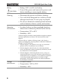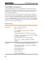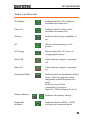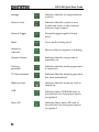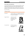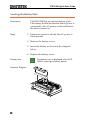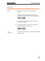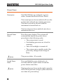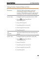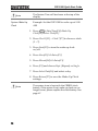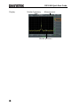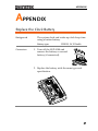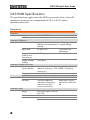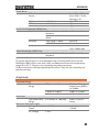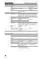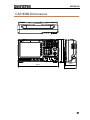
1
Spectrum Analyzer GSP-9300 QUICK START GUIDE GW INSTEK PART NO. 82SP-930A0M01 ISO-9001 CERTIFIED MANUFACTURER This manual contains proprietary information, which is protected by copyright. All rights are reserved. No part of this manual may be photocopied, reproduced or translated to another language without prior written consent of Good Will company. The information in this manual was correct at the time of printing. However, Good Will continues to improve products and reserves the rights to change specification, equipment, and maintenance procedures at any time without notice. Good Will Instrument Co., Ltd. No. 7-1, Jhongsing Rd., Tucheng Dist., New Taipei City 236, Taiwan. Table of Contents Table of Contents SAFETY INSTRUCTIONS ................................................... 2 GETTING STARTED ........................................................... 7 GSP-9300 Introduction .......................... 8 Accessories .......................................... 11 Appearance .......................................... 13 First Use Instructions .......................... 25 BASIC OPERATION ......................................................... 37 Viewing a Signal .................................. 37 Using the Marker Function .................. 39 Interface Configuration ........................ 41 APPENDIX ...................................................................... 47 Replace the Clock Battery ..................... 47 GSP-9300 Specifications ...................... 48 GSP-9300 Dimensions ......................... 57 Declaration of Conformity .................... 58 1 GSP-9300 Quick Start Guide SAFETY INSTRUCTIONS This chapter contains important safety instructions that you must follow during operation and storage. Read the following before any operation to ensure your safety and to keep the instrument in the best possible condition. Safety Symbols These safety symbols may appear in this manual or on the instrument. WARNING Warning: Identifies conditions or practices that could result in injury or loss of life. CAUTION Caution: Identifies conditions or practices that could result in damage to the instrument or to other properties. DANGER High Voltage Attention Refer to the Manual Earth (ground) Terminal Frame or Chassis Terminal Do not dispose electronic equipment as unsorted municipal waste. Please use a separate collection facility or contact the supplier from which this instrument was purchased. 2 SAFETY INSTRUCTIONS Safety Guidelines General Guideline CAUTION Do not place any heavy object on the instrument. Avoid severe impact or rough handling that leads to damaging the instrument. Do not discharge static electricity to the instrument. Use only mating connectors, not bare wires, for the terminals. Ensure signals to the RF input do not exceed +30dBm. Ensure reverse power to the TG output terminal does not exceed +30dBm. Do not supply any input signals to the TG output. Do not block the cooling fan opening. Do not disassemble the instrument unless you are qualified. (Measurement categories) EN 61010-1:2010 specifies the measurement categories and their requirements as follows. The instrument falls under category II. Measurement category IV is for measurement performed at the source of low-voltage installation. Measurement category III is for measurement performed in the building installation. Measurement category II is for measurement performed on the circuits directly connected to the low voltage installation. Measurement category I is for measurements performed on circuits not directly connected to Mains. Power Supply WARNING AC Input voltage range: 100V~240V Frequency: 50/60Hz To avoid electrical shock connect the protective grounding conductor of the AC power cord to an earth ground. 3 GSP-9300 Quick Start Guide Battery CAUTION Cleaning Operation Environment Rating: 10.8V, 6 cell Li-ion battery Turn off the power and remove the power cord before installing or removing the battery. Disconnect the power cord before cleaning. Use a soft cloth dampened in a solution of mild detergent and water. Do not spray any liquid. Do not use chemicals containing harsh material such as benzene, toluene, xylene, and acetone. Location: Indoor, no direct sunlight, dust free, almost non-conductive pollution (Note below) Temperature: 5°C to 45°C Humidity: <90% (Pollution Degree) EN 61010-1:2010 specifies the pollution degrees and their requirements as follows. The instrument falls under degree 2. Pollution refers to “addition of foreign matter, solid, liquid, or gaseous (ionized gases), that may produce a reduction of dielectric strength or surface resistivity”. Pollution degree 1: No pollution or only dry, non-conductive pollution occurs. The pollution has no influence. Pollution degree 2: Normally only non-conductive pollution occurs. Occasionally, however, a temporary conductivity caused by condensation must be expected. Pollution degree 3: Conductive pollution occurs, or dry, nonconductive pollution occurs which becomes conductive due to condensation which is expected. In such conditions, equipment is normally protected against exposure to direct sunlight, precipitation, and full wind pressure, but neither temperature nor humidity is controlled. Storage environment 4 Location: Indoor Temperature: -20°C to 70°C Humidity: <90% SAFETY INSTRUCTIONS Disposal Do not dispose this instrument as unsorted municipal waste. Please use a separate collection facility or contact the supplier from which this instrument was purchased. Please make sure discarded electrical waste is properly recycled to reduce environmental impact. 5 GSP-9300 Quick Start Guide Power cord for the United Kingdom When using the instrument in the United Kingdom, make sure the power cord meets the following safety instructions. NOTE: This lead/appliance must only be wired by competent persons WARNING: THIS APPLIANCE MUST BE EARTHED IMPORTANT: The wires in this lead are coloured in accordance with the following code: Green/ Yellow: Earth Blue: Neutral Brown: Live (Phase) As the colours of the wires in main leads may not correspond with the coloured marking identified in your plug/appliance, proceed as follows: The wire which is coloured Green & Yellow must be connected to the Earth terminal marked with either the letter E, the earth symbol or coloured Green/Green & Yellow. The wire which is coloured Blue must be connected to the terminal which is marked with the letter N or coloured Blue or Black. The wire which is coloured Brown must be connected to the terminal marked with the letter L or P or coloured Brown or Red. If in doubt, consult the instructions provided with the equipment or contact the supplier. This cable/appliance should be protected by a suitably rated and approved HBC mains fuse: refer to the rating information on the equipment and/or user instructions for details. As a guide, a cable of 0.75mm2 should be protected by a 3A or 5A fuse. Larger conductors would normally require 13A types, depending on the connection method used. Any exposed wiring from a cable, plug or connection that is engaged in a live socket is extremely hazardous. If a cable or plug is deemed hazardous, turn off the mains power and remove the cable, any fuses and fuse assemblies. All hazardous wiring must be immediately destroyed and replaced in accordance to the above standard. 6 GETTING STARTED GETTING STARTED This chapter provides a brief overview of the GSP-9300, the package contents, instructions for first time use and an introduction to the front panel, rear panel and GUI. GSP-9300 Introduction ...................................................... 8 Main Features ............................................................................................................. 8 Accessories ..................................................................... 11 Appearance ..................................................................... 13 GSP-9300 Front Panel ............................................................................................ 13 Rear Panel ................................................................................................................. 18 Display ....................................................................................................................... 20 Status Icon Overview .............................................................................................. 23 First Use Instructions ...................................................... 25 Tilting the Stand ....................................................................................................... 25 Inserting the Battery Pack....................................................................................... 26 Power UP .................................................................................................................. 27 Power Down ............................................................................................................ 28 Setting the Date, Time and Wake-Up Clock ........................................................ 29 Firmware Update ..................................................................................................... 31 Restoring Default Settings ...................................................................................... 32 Conventions.............................................................................................................. 33 7 GSP-9300 Quick Start Guide GSP-9300 Introduction The GSP-9300 builds on the strong feature set of the GSP-930 and significantly increases performance in almost every aspect; making this the most comprehensive and feature-rich spectrum analyzer GW Instek has released. Like the GSP-930, the GSP-9300 features a split window display to view data in spectrum, topographic or spectrographic views. There are also a number of additional test functions such as 2FSK, 1PdB and new dedicated EMC pretest functions for EMI and EMS testing. Lastly, the GSP-9300 significantly reduces the sweep time and RBW filter step resolution and complexity. Main Features Performance Features 8 9kHz~3GHz bandwidth 1Hz resolution Nominal RBW accuracy of ±5% <1MHz, ±8% =1MHz Video bandwidth 1Hz~1MHz (1-3-10 steps) Amplitude measurement range: DANL~30dBm (frequency dependent) Input attenuation: 0 ~ 50dB, 1dB steps Phase noise: < -88dBc/Hz@1GHz, 10kHz, typical 1-3-10 step increments for RBW bandwidth Three display modes: Spectrum, Topographic and Spectrographic Split window display Built-in EMI filter Auto Wake-up Built-in preamplifier GETTING STARTED Gate sweep Marker Frequency counter Two operating modes: Spectrum and Power Meter mode EMI Pretest functions SEM measurement ACPR measurement OCBW measurement 2FSK measurement Phase jitter measurement Harmonics measurement P1dB measurement Channel power measurement Demodulation analyzer Diverse marker functions and features with Peak Table Sequence function to automatically perform preprogrammed sequential operations Optional battery operation 9 GSP-9300 Quick Start Guide Interface 10 8.4 color LCD (800600) On-screen menu icons DVI-I video output RS-232 with RTS/CTS hardware flow control USB 2.0 with support for USB TMC LAN TCP/IP with LXI support Optional GPIB/IEEE488 interface Optional 3G USB adapter for WLAN Optional power meter adapter IF output @ 886MHz Headphone output REF (reference clock) input/output BNC ports Alarm/Open collector output BNC port Trigger/Gate input BNC ports RF N-type input port Tracking generator output DC +7V/500mA output SMB port GETTING STARTED Accessories Standard Accessories Options Optional Accessories Part number Description Region dependant Power cord N/A User manual CD: Includes: User manual, Programming manual, SpectrumShot quick start guide, SpectrumShot software, IVI driver N/A Quick start guide N/A Certificate of calibration Region dependant Power cord Option number Description Opt1. Tracking generator Opt2. Battery (11.1V/5200mAH Li-ion battery) Opt3. GPIB interface (IEEE 488 bus) Part number Description ADB-002 DC block BNC 50R 10MHz2.2GHz ADB-006 DC BLOCK N TYPE 50R 10MHz-6GHz ADB-008 DC BLOCK SMA 50R 0.1MHz-8GHz GSC-009 Soft Carrying Case PWS-06 USB Average Power Sensor (up to 6200 MHz; -32 to 20 dBm) GRA-415 6U Rack mount kit 11 GSP-9300 Quick Start Guide Software Downloads PC Software for Windows System (SpectrumShot quick start guide, SpectrumShot software) IVI Driver Supports LabView & LabWindows/CVI Programming Android System (“GSP-9300 Remote Control”, available on Google play.) 12 GETTING STARTED Appearance GSP-9300 Front Panel LCD display Function keys GSP-9300 Main keys Control keys File keys Power key Spectrum Analyzer 9 kHz Marker keys CONTROL 3 GHz Frequency BW / AVG Sweep Span Measure EMC Pretest Sweep Mode FILE Preset/Local and Quick Save keys File Fast/ Normal MARKER AUXILIARY Marker Sequence F1 Amplitude Trace Limit Line Save Autoset Display Trigger Recall Option Control Marker F2 Peak Search System Auxillary keys F3 Scroll wheel Preset 7 8 9 4 5 6 Quick Save 1 2 3 BK SP F4 LOCAL F5 F6 / 0 Arrow keys Enter F7 TG OUTPUT 50 DC ± 50 V W MAX. REV PWR + 30 dBm USB A, Micro SD port LCD display Function keys Main keys Tracking generator output 500 mA MAX . DC 7 V OUTPUT Numeric, Enter and BK SP keys RF INPUT 50 DC ±50 V W MAX. + 30 dBm MAX . RF input terminal DC power supply 800600 color LCD display. The display shows the soft keys for the current function, frequency, amplitude and marker information. F1 ~ Frequency F7 The F1 to F7 function keys directly correspond to the soft keys on the right-hand side of display. Sets the center frequency, start frequency, stop frequency, center frequency step and frequency offset values. 13 GSP-9300 Quick Start Guide Span Amplitude Autoset Control keys BW/Avg Sweep Sweep Mode Measure EMC Pretest Trace Limit Line 14 Sets the span, with options for full span, zero span and last span. Sets the amplitude reference level, attenuation, pre-amplifier controls, scale and other options for attenuation and scale. Automatically searches the peak signal with maximum amplitude and displays it with appropriate horizontal and vertical scales. Sets the resolution bandwidth, video bandwidth, average type and turns the EMI filter on/off. Sets the sweep time and gate time. Toggles the Sweep Control between Fast and Normal mode. Accesses measurement options such as ACPR, OCBW, demodulation measurements, SEM, TOI, 2FSK, phase jitter and other advanced measurements. Dedicated EMI testing and setup menu. Sets traces and trace related functions. Sets and tests Pass/Fail limit lines. GETTING STARTED Display Trigger File Marker File Sets the triggering modes. File utilities options Save Save the trace, state etc., and save options. Recall Recall the trace, state etc., and recall options. Marker Turns the Markers on/off and configures the markers. Marker Peak Search Auxiliary The Display key configures the windowing mode and basic display properties. Sequence Option Control System The Marker key positions the markers on the trace. Finds each maximum and minimum peak. Used with the Marker function. Access, set and edit program sequences. The Option Control key allows you to setup optional accessories such as the Tracking Generator, Power Meter or Demo Kit. The System key shows system information, settings and other system related functions. 15 GSP-9300 Quick Start Guide Preset / Local key Preset LOCAL The Preset key will restore the spectrum analyzer to the Factory or User Preset settings. The Preset key will also return the instrument back to local control after it has been in remote control mode. Quick Save The Quick Save utility allows you to save either the state, trace, display screen, limit line, correction or sequence with only a single press. Power key Turns the instrument on/off. On = yellow, off = blue. Scroll wheel Edit values, select listed items. Arrow keys Increment/decrement values (in steps), select listed items. RF input terminal RF input port. Accepts RF inputs. RF INPUT 50W DC ±50V MAX. +30dBm MAX. 16 Maximum input: +30dBm Input impedance: 50Ω Maximum DC voltage: ±50V N-type: female GETTING STARTED SMB port supplies power for optional accessories. DC power supply 500mA MAX. DC 7V OUTPUT DC +7V 500mA Max. Numeric keypad 7 8 9 4 5 6 1 2 3 BK SP / Enter 0 The Tracking Generator (TG) output source. TG output port TG OUTPUT 50 W DC ±50V MAX. REV PWR +30dBm USB A, Micro SD The numeric keypad is used to enter values and parameters. It is often used in conjunction with the arrow keys and scroll wheel. N-type: female Input impedance: 50Ω Output power: -50dBm to 0dBm Maximum reversed power: +30dBm USB A port, Micro SD port for saving/recalling settings/files. 17 GSP-9300 Quick Start Guide Rear Panel IF OUT DVI-I port USB-B, LAN port Power socket Fan RS232 port TRIG IN/GATE IN port AC 100 240V 50 60 Hz 82W MAX. ALARM OUT/ OPEN COLLECTOR REF OUT REF IN GPIB port (optional) Battery cover/ Optional battery pack RS232 RS232 9 pin DSUB port. IF OUT SMA IF Out port. DVI-I DVI video out port. Supports SVGA (800X600) @ 60Hz. Fan Power Socket 18 Power Socket: 100~240V, 50/60Hz. GETTING STARTED Battery pack Voltage: 10.8V Capacity: 5200mAH REF IN BNC female reference input. REF OUT BNC female reference output: 10MHz, 50Ω impedance Security Lock ALARM OUT BNC female open collector Alarm output. TRIG IN/GATE IN BNC female 3.3V CMOS trigger input/gated sweep input. Phone 3.5mm stereo headphone jack (wired for mono operation) USB B USB B Device port. USB 1.1/2.0 LAN RJ-45 10Base-T/100Base-Tx 19 GSP-9300 Quick Start Guide Display Attenuation level Date and time Marker information LXI icon Sweep settings Scale and Reference level Trace/ Detection settings Traces and waveforms Unassigned setting icons Sweep progress bar Entry / Message area Function menu Frequency/Bandwidth settings Status icons Sweep, Trigger, Pre-amp and USB settings Scale Displays the vertical scale of the vertical grid. Reference level Displays the reference level. Attenuation Displays the vertical scale (attenuation) of the input signal. Date/Time Displays the date and time. Marker information Displays marker information. LXI icon This icon indicates the status of the LXI connection. Function menu Soft menu keys associated with the F1 to F7 function keys to the right of the display. 20 GETTING STARTED Sweep Mode This icon displays the sweep mode, as set by the Sweep Mode key. Sweep settings Sweep icon that shows the sweep status. Trace and detection settings Trace icon that shows the trace type and the detection mode used for each trace. Blank Unassigned setting icons. Trigger settings Trigger icon that shows the trigger status. Pre-amp settings Pre-amplifier icon that shows the Pre-amplifier status. USB settings Displays the status of the USB A port. Status Icons Displays the interface status, power source status and alarm status, etc. See the Status Icon Overview on page 23 for a list of the status icons. Frequency/ Bandwidth settings Displays the Start, Center and Stop frequencies, RBW, VBW, Span and Sweep settings. Entry/Message area This area is used to show system messages, errors and input values/parameters. Trace and waveforms Main display showing the input signals, traces, limit lines and marker positions. 21 GSP-9300 Quick Start Guide Sweep progress bar 22 The sweep progress bar shows the progress of slow sweeps (greater than 2 seconds). GETTING STARTED Status Icon Overview 3G Adapter Indicates that the 3G adapter is installed and turned on. Demo Kit Indicates that the demo kit is installed and turned on. PreAmp Indicates that the pre amplifier is on. AC Shown when running on AC power. AC Charge Shown when the AC power is charging the battery. Alarm Off Alarm buzzer output is currently off. Alarm On Alarm buzzer output is currently on. Amplitude Offset Indicates that the amplitude-shift is active. This icon appears when amplitude-related functions are used: Reference level offset Amplitude Correction Input Z = 75Ω and Input Z cal >0 Battery indicator Bandwidth Indicator ~ Indicates the battery charge. Indicates that the RBW or VBW settings are in manual mode. 23 GSP-9300 Quick Start Guide Average Indicates that the Average function is active. External Lock Indicates that the system is now locked and refers to the external reference input signal External Trigger External trigger signal is being used. Math Trace math is being used. Sequence Indicator Shown when a sequence is running. Sweep Indicator Indicates that the sweep time is manually set. Tracking generator Indicates that the tracking generator is turned on. TG Normalization Indicates that the tracking generator has been normalized. Wake-up clock Indicates that the wake-up clock is turned on. USB Indicates that a USB flash drive is inserted into the front panel and is recognized. Micro SD Indicates that a micro SD card is inserted into the front panel and is recognized. 24 GETTING STARTED First Use Instructions Use the procedures below when first using the GSP-9300 to tilt the stand, insert the battery pack, power up the instrument, set the internal clock, set the wake-up clock, update the firmware and to restore the default settings. Lastly, the Conventions sections will introduce you to the basic operating conventions used throughout the user manual. Tilting the Stand Description The GSP-9300 has two adjustable rubber feet that can used to position the instrument into two preset orientations. Upright Position Tuck the feet under the bottom of the instrument to stand the instrument upright. Leaning Position Pull the feet back to have the instrument leaning back. 25 GSP-9300 Quick Start Guide Inserting the Battery Pack Description Steps The GSP-9300 has an optional battery pack. The battery should be inserted before power is connected to the AC power socket and before the unit is turned on. 1. Ensure the power is off and the AC power is disconnected. 2. Remove the battery cover. 3. Insert the battery as shown in the diagram below. 4. Replace the battery cover. Display Icon Insertion Diagram 26 The battery icon is displayed when GSP9300 is running on battery power. GETTING STARTED Power UP Steps 1. Insert the AC power cord into the power socket. 2. The power button exterior will be lit blue to indicate that the GSP-9300 is in standby mode. 3. Press the power button for a few seconds to turn the GSP-9300 on. 4. The power button will turn orange and the GSP-9300 will start to boot up. Note It takes a little less than 1 minute for the GSP-9300 to fully startup. 27 GSP-9300 Quick Start Guide Power Down Description The GSP-9300 has two methods to power down: Normal and Forced Power Down. The normal power down method will save the system state and end any running processes. The state is saved for the next time the instrument is turned back on. The forced power down method only does a minimum state save. Normal Power Down Note Forced Power Down Note 28 Press the power button. The system will automatically handle the power down procedure in the following order: The system state is saved. Outstanding processes are closed in sequence. The LCD backlight is turned off. The system enters standby mode (the power key changes from orange to blue). The process takes ~10 seconds. Press and hold the power button for ~4 seconds until the system turns off and the power button turns blue. The forced power down mode might cause the GSP-9300 to perform a longer system check the next time it is powered up. GETTING STARTED Setting the Date, Time and Wake-Up Clock Description The GSP-9300 can be setup to power-up automatically using the Wakeup Clock function. This feature is useful to wake-up the instrument early and eliminate settling time. System Date Example: Set the System Date to July 1, 2014 1. Press System >Date/Time[F4]>Set Date[F1]>Year[F1]. 2. Press 2014>Enter[F1]. 3. Press Month[F2]>7>Enter[F1]. 4. Press Day[F3]>1>Enter[F1]. 5. Press Return[F7]. Note System Time The System Date will be shown at the top of the display. Example: Set the System Time to 9.00 AM 1. Press System >Date/Time[F4]>Set Time[F2]>Hour[F1]. 2. Press 9>Enter[F1]. 3. Press Minute[F2]>0>Enter[F1]. 4. Press Second[F3]>0>Enter[F1]. 5. Press Return[F7]. 29 GSP-9300 Quick Start Guide Note System Wake-Up Clock The System Time will be shown at the top of the display. Example: Set the GSP-9300 to wake up at 9.00 AM 1. Press System >Date/Time[F4]>Wake-Up Clock[F3]>Select Clock[F1]. 2. Press Clock 1[F1] ~ Clock 7[F7] to choose a clock (1 ~ 7). 3. Press State[F2] to turn the wake up clock on/off. 4. Press Hour[F3]>9>Enter[F1]. 5. Press Minute[F4]>0>Enter[F1]. 6. Press [F5] and choose Rept. (Repeat) or Single. 7. Press Select Date[F6] and select a day. 8. Press Return[F7] to save the Wake-Up Clock settings. Note 30 The system time is kept with the CR2032 clock battery. If the system time/ wake up clock can no longer be set, please replace the clock battery. See page 47. GETTING STARTED Firmware Update Description The GSP-9300 allows the firmware to be updated by end-users. Before using the GSP9300, please check the GW Instek website or ask your local distributor for the latest firmware. System version Before updating the firmware, please check the firmware version. 1. Press System >System Information[F1]. 2. The firmware will be listed on the display. Firmware: T. 2. 0.1.2 3. Press any other main/control/file/marker /auxiliary key to exit out of the System Information screen. 4. To upgrade the firmware, insert the new firmware onto a USB flash drive or Micro SD card and put the drive/card into the appropriate front panel port. The firmware files should be located in a directory named “gsp931”. 31 GSP-9300 Quick Start Guide 5. Press System >More 1/2[F7]>Upgrade[F2]. 6. The spectrum analyzer will automatically find the firmware on the USB flash drive and start to update the firmware. When finished, the message “Upgrade is finished” will be shown at the bottom of the screen followed by “Rebooting”. Rebooting 7. The system will automatically restart after the rebooting message. Note The upgrade process may take a few minutes. Restoring Default Settings Description Steps The factory default settings or user presets can be easily restored using the Preset key on the front panel. By default, the factory default settings are restored with the Preset key. 1. Press Preset . 2. The spectrum analyzer will load the preset settings. 32 GETTING STARTED Conventions The following conventions are used throughout the user manual. Read the conventions below for a basic grasp of how to operate the GSP-9300 menu system and front panel keys. Soft Menu keys The F1 to F7 function keys on the right side of the display correspond directly to the softmenu keys on their left. F1 ~ F7 function keys Soft-menu keys GSP-9300 CONTROL Spectrum Analyzer 9 kHz 3 GHz Sweep Mode Frequency BW/AVG Sweep Span Measure EMC Pretest File Amplitude Trace Limit Line Save Autoset Display Trigger Recall FILE Fast/ Normal MARKER Marker AUXILIARY Sequence F1 Marker Option Control F2 Peak Search System F3 7 8 9 4 5 6 Quick Save 1 2 3 BK SP / Enter F4 Preset LOCAL F5 F6 0 F7 TG OUTPUT 50 W DC ±50V MAX. REV PWR +30dBm 500mA MAX. DC 7V OUTPUT RF INPUT 50 W DC ±50V MAX. +30dBm MAX. Input Parameter Values Selecting this type of menu key will allow you to enter a new value with the numeric keypad or increment/decrement the value using the scroll wheel. Toggle State Pressing this menu key will toggle the state. 33 GSP-9300 Quick Start Guide Toggle State & Input Parameter Pressing this menu key will allow you to toggle the state of the function between Auto and Man(ual) state. When in the Man state, the parameter value can be manually edited. Use the numeric keypad to enter the new value or use the scroll wheel to increment/decrement the current value. Sub Menu Pressing this menu key will enter a submenu. Sub Menu to select parameter Pressing this menu key will enter a submenu to select a parameter. Active Function Pressing this type of menu key will activate that function. The menu key will be highlighted to show it is the active function. 34 GETTING STARTED Parameter input Numerical keypad 7 8 9 Scroll wheel Preset LOCAL 4 5 6 Quick Save 1 2 3 BK SP / Enter 0 Directional arrow keys Backspace, Enter keys Parameter values can be entered using the numeric keypad, the scroll wheel and occasionally with the arrow keys. Using the numeric keypad When prompted to enter a parameter, use the number keys (0~9), the decimal key (.) and the sign key (+/-) to enter a value. After a value has been entered, the soft-menu keys can be used to select the units. The value of the parameter is shown at the bottom of the screen as it is edited. Values can include decimal points for non-integer values or for entering dot-decimal notation for IP addresses. Span: 10 Edited parameter Back Space Use the backspace key to delete the last character or number entered. 35 GSP-9300 Quick Start Guide Using the scroll wheel Use the scroll wheel to alter the current value. Clockwise increases the value, anti-clockwise decreases the value. Directional arrows Use the directional arrows to select discrete parameters or to alter values by a coarser resolution than the scroll wheel. Left decreases the value, right increases the value. 36 BASIC OPERATION BASIC OPERATION The Basic Operation chapter in this Quick Start Guide only covers a few basic operations: how to view a signal, how to use a marker to make a measurement and how to setup the LXI interface. For comprehensive operating instructions, please see the user manual on the accompanying User Manual CD. Viewing a Signal Description Operation This section will give a brief overview on how to view signals from the rear panel REF out terminal. Only the basic settings will be shown. 1. Press Preset . This will restore the factory default settings. See the user manual for details. 2. Connect the REF out signal from the rear panel to the RF Input on the front panel. RF INPUT 50W DC ±50V MAX. +30dBm MAX. 37 GSP-9300 Quick Start Guide 3. Press Frequency >Center[F1] and enter 10MHz. This is the output frequency of the REF out signal. 4. Press Amplitude >Ref Level[F1] and set the reference level to 17dBm. 5. Press Span and enter a span of 10MHz. This will set the start frequency to 5MHz and the stop frequency to 15MHz. Display Reference Level: 17dBm Center Frequency 38 Span BASIC OPERATION Using the Marker Function Description Operation This section will describe how to activate and move a normal marker. The noise marker function will also be used to show how to make a basic marker measurement. 1. Use the procedure described in the previous section to display a signal from the REF out terminal. 2. Press Marker > Select Marker[F1] and select marker number 1. 3. Press [F2] and turn the marker 1 on. 4. Press Normal[F3] and set the marker position to 12 MHz using either the keypad, scroll wheel or arrow keys. 5. Press Function[F5]>Marker Noise[F2] and turn the marker noise function on. The noise marker function calculates the average noise level over a bandwidth of 1Hz, referenced from the marker position. 39 GSP-9300 Quick Start Guide Display Marker frequency Measurement Marker position 40 BASIC OPERATION Interface Configuration The GSP-9300 supports USB, RS-232, GPIB(optional), WLAN and LAN based LXI interfaces for remote control. This Quick Start Guide only details how to connect to a LAN to access the LXI browser interface for remote control and configuration. Please see the programming manual or user manual on the accompanying User Manual CD for further details. Configure the LAN and LXI Interface The GSP-9300 is a class C LXI compliant instrument. The LXI specification allows instrumentation to be configured for basic remote control or monitoring over a LAN or WLAN. The GSP-9300 also supports HiSlip. HiSlip (High-Speed LAN Instrument Protocol) is an advanced LAN based standard for 488.2 communications. For details on the LXI specification, compliance classes and HiSLIP, please see the LXI website @ http://www.lxistandard.org. Background The LAN interface is used for remote control over a network. The spectrum analyzer supports DHCP connections so the instrument can be automatically connected to an existing network. Alternatively, network settings can also be manually configured. LAN configuration Settings IP Address Default Gateway Subnet Mask DNS Server Connection Connect an Ethernet cable from the network to the rear panel LAN port. DHCP on/off 41 GSP-9300 Quick Start Guide 1. Press System >More[F7]>RmtInterface[F1]> LAN[F2]>LAN Config[F1] to set the LAN settings: IP Address[F1] Subnet Mask[F2] Default Gateway[F3] DNS Server[F4] LAN Config[F5] Sets the IP address. Sets the subnet mask. Sets the default gateway. Sets the DNS server address Toggles the LAN configuration between DHCP and manual IP settings. 2. Press Apply[F6] to confirm the LAN configuration settings. Display Icon The LXI icon turns green when connected to a LAN and will flash if the “Identification” setting is on, see page 44. The password on the LXI webpage can be set from the spectrum analyzer. The password is shown in the system information. Set Password 3. Press System >More[F7]>RmtInterface Config[F1]>LAN[F2]>LXIPassword[F3] to set the password. 4. Enter the password using the F1~F7 keys, as shown below, or use the numeric keypad to enter numbers: 42 Limitations: No spaces Only 1~9, A~Z, a~z characters allowed 7 8 9 4 5 6 1 2 3 0 / BASIC OPERATION A B Rename> C a ABCDE D b FGHIJ E c KLMNO Lowercase d PQRST Return e UVWXY Z Return Return Cancel password Menu tree to enter the password 5. The password appears on the bottom of the screen as it is created. Password 6. Press Hi SLIP Port Reset LAN Enter to confirm setting the password. 7. Press System >More[F7]>RmtInterface Config[F1]>LAN[F2] >HiSLIPPort to see the Hi Slip Port number. 4880 HiSlip port It may be necessary to reset the LAN configuration settings before the LAN can be used. 8. Press System >More[F7]>RmtInterface Config[F1]>LAN Reset[F3] to reset the LAN. 43 GSP-9300 Quick Start Guide LXI Browser Interface and Function Check Functionality check Enter the IP address of the spectrum analyzer in a web browser after the instrument has been configured and connected to the LAN (page 41). http:// XXX.XXX.XXX.XXX The web browser interface appears: Welcome Page Note 44 The Welcome Page lists all the LXI and LAN configuration settings as well as the instrument identification. The instrument identification can be turned on/off from this page. The LXI icon in the GSP-9300 display will flash when the Identification setting is turned on. BASIC OPERATION View & Modify Configuration The View & Modify Configuration allows you to modify the LAN settings from the browser. Press the Modify Configuration button to modify any of the configuration files. A password must be entered to alter the settings. Default password: lxiWNpwd [Note: password is case sensitive.] 45 GSP-9300 Quick Start Guide SCPI Command The SCPI Command page allows you to enter SCPI commands directly from the browser for full remote control. Please see the programming manual for details. A password must be entered before remote commands can be used. Default password: lxiWNpwd [Note: password is case sensitive.] Get Image Note 46 The Get Image page allows the browser to remotely capture a screenshot of the GSP-9300 display. For further details, please see the programming manual, available on the GW Instek web site @ www.gwinstek.com. APPENDIX APPENDIX Replace the Clock Battery Background The system clock and wake-up clock keep time using a button battery. Battery type: Connection CR2032, 3V, 210mAh 1. Turn off the GSP-9300 and remove the battery cover and battery (if connected). 2. Replace the battery with the same type and specification. 47 GSP-9300 Quick Start Guide GSP-9300 Specifications The specifications apply when the GSP is powered on for at least 30 minutes to warm-up to a temperature of 20˚C to 30˚C, unless specified otherwise. Frequency Frequency Range Resolution Frequency Reference Accuracy Aging Rate Frequency Stability over Temperature Supply Voltage Stability Frequency Readout Accuracy Start, Stop, Center, Marker Trace points Marker Frequency Counter Resolution Accuracy Frequency Span Range Resolution Accuracy 48 9 kHz to 3.0 GHz 1 Hz ±(period since last adjustment X aging rate) + stability over temperature + supply voltage stability ±2 ppm max. 1 year after last adjustment ±0.025 ppm 0 to 50 °C ±0.02 ppm ±(marker frequency indication X frequency reference accuracy + 10% x RBW + frequency resolution1) Max 601 points, min 6 points 1 Hz, 10 Hz, 100 Hz, 1 kHz ±(marker frequency RBW/Span >=0.02 ; indication X frequency Mkr level to DNL>30 reference accuracy + dB counter resolution) 0 Hz (zero span), 100 Hz to 3 GHz 1 Hz ± frequency resolution1 RBW: Auto; APPENDIX Phase Noise Offset from Carrier Fc =1 GHz; RBW = 1 kHz, VBW = 10 Hz; Average ≥ 40 10 kHz <-88 dBc/Hz 100 kHz <-95 dBc/Hz 1 MHz <-113 dBc/Hz Resolution Bandwidth (RBW) Filter Filter Bandwidth 1 Hz to 1 MHz in 1-3-10 sequence 200 Hz, 9 kHz, 120 kHz, 1MHz Accuracy ± 8%, RBW = 1MHz ± 5%, RBW < 1MHz Shape Factor < 4.5:1 Typical2 Typical Typical -3dB bandwidth -6dB bandwidth Nominal3 Nominal Normal Bandwidth ratio: -60dB:-3dB Video Bandwidth (VBW) Filter Filter Bandwidth 1 Hz to 1 MHz in 1-3-10 -3dB bandwidth sequence [1] Frequency Resolution = Span/(Trace points - 1) [2] Typical specifications in this datasheet mean that the performance can be exhibited in 80% of the units with a 95% confidence level over the temperature range 20 to 30 °C. They are not covered by the product warranty. [3] Nominal values indicate expected performance. They are not covered by the product warranty. Amplitude Amplitude Range Measurement Range 100 kHz to 1 MHz 1 MHz to 10 MHz 10 MHz to 3 GHz Displayed Average Noise Level (DANL) to 18 dBm DANL to 21 dBm DANL to 30 dBm Attenuator Input Attenuator 0 to 50 dB, in 1 dB step Range Maximum Safe Input Level Average Total ≤ +33 dBm Power DC Voltage ± 50 V Auto or manual setup Input attenuator ≥10 dB 49 GSP-9300 Quick Start Guide 1 dB Gain Compression Total Power at 1st > 0 dBm Typical;Fc ≥ 50 MHz; Mixer preamp. off Total Power at the > -22 dBm Typical;Fc ≥ 50 MHz; Preamp preamp. on mixer power level (dBm)= input power (dBm)attenuation (dB) Displayed Average Noise Level (DANL)4 Preamp off 0 dB attenuation; RF Input is terminated with a 50Ω load. RBW 10 Hz; VBW 10 Hz; span 500 Hz; reference level = -60dBm; trace average ≥ 40 9 kHz to 100 kHz < -93 dBm 100 kHz to 1 < -90 dBm - 3 x (f/100 MHz kHz) dB Nominal 1 MHz to 10 MHz < -122 dBm 10 MHz to 3 GHz < -122 dBm Preamp on 0 dB attenuation; RF Input is terminated with a 50Ω load ; RBW 10 Hz; VBW 10Hz; span 500 Hz; reference level = -60dBm; trace average ≥ 40 100 kHz to 1 < -108 dBm - 3 x (f/100 MHz kHz) dB 1 MHz to 10 MHz < -142 dBm Nominal 10 MHz to 3 GHz < -142 dBm + 3 x (f/1 GHz) dB [4] DANL spec excludes spurious response. Level Display Range4 Scales Units Marker Level Readout Level Display Modes Number of Traces Detector Trace Functions 50 Log, Linear dBm, dBmV, dBuV, V, W 0.01 dB 0.01 % of reference level Trace, Topographic, Spectrogram 4 Positive-peak, negativepeak, sample, normal, RMS(not Video) Clear & Write, Max/Min Hold, View, Blank, Average Log scale Linear scale Single / split Windows Can be setup for each trace separately APPENDIX Absolute Amplitude Accuracy Absolute Point Preamp off Preamp on Frequency Response Preamp off 100 kHz to 2.0 GHz 2GHz to 3 GHz Preamp on Center=160 MHz ; RBW 10 kHz; VBW 1 kHz; span 100 kHz; log scale; 1 dB/div; peak detector; 20 to 30°C; signal input: 0 dBm ± 0.3 dB Ref level 0 dBm; 10 dB RF attenuation ± 0.4 dB Ref level -30 dBm; 0 dB RF attenuation Attenuation: 10 dB; Reference: 160 MHz; 20 to 30°C ± 0.5 dB ± 0.7 dB Attenuation: 0 dB; Reference: 160 MHz; 20 to 30°C 1 MHz to 2 GHz ± 0.6 dB 2 GHz to 3 GHz ± 0.8 dB Attenuation Switching Uncertainty Attenuator setting 0 to 50 dB in 1 dB step Uncertainty ± 0.15 dB reference: 160 MHz, 10dB attenuation RBW Filter Switching Uncertainty 1 Hz to 1 MHz ± 0.25 dB reference : 10 kHz RBW Level Measurement Uncertainty Overall Amplitude ± 1.5 dB 20 to 30°C; frequency > 1 MHz; Accuracy Signal input 0 to -50 dBm; Reference level 0 to -50 dBm; Input attenuation 10 dB; RBW 1 kHz; VBW 1 kHz; after cal; Preamp Off ± 0.5 dB Typical 51 GSP-9300 Quick Start Guide Spurious Response Second Harmonic Intercept +35 dBm +60 dBm Third-order Intercept Input Related Spurious Residual Response (inherent) > 1dBm < -60 dBc <-90 dBm Preamp off; signal input -30dBm; 0 dB attenuation Typical; 10 MHz < fc < 775 MHz Typical; 775 MHz ≤ fc < 1.5 GHz Preamp off; signal input -30dBm; 0 dB attenuation 300 MHz to 3 GHz Input signal level -30 dBm, Att. Mode, Att=0dB; 20-30ºC Input terminated; 0 dB attenuation; Preamp off Sweep Sweep Time Range 310 us to 1000 s 50 us to 1000 s Span > 0 Hz Span = 0 Hz; Min Resolution = 10 us Sweep Mode Trigger Source Trigger Slope Continuous; Single Free run; Video; External Positive or negative edge RF Preamplifier Frequency Range 1 MHz to 3 GHz Gain 18 dB Nominal (installed as standard) Front Panel Input/Output RF Input Connector Type Impedance VSWR 52 N-type female 50 ohm <1.6 :1 Nominal 300 kHz to 3 GHz; Input attenuator ≥ 10 dB APPENDIX Power for Option Connector Type Voltage/Current SMB male DC +7V / 500 mA max With short-circuit protection USB Host Connector Type Protocol A plug Version 2.0 MicroSD Socket Protocol SD 1.1 Supported Cards microSD, microSDHC Supports Full/High/Low speed Up to 32GB capacity Rear Panel Input/Output Reference Output Connector Type BNC female Output Frequency 10 MHz Nominal Output 3.3V CMOS Amplitude Output 50 ohm Impedance Reference Input Connector Type BNC female Input Reference 10 MHz Frequency Input Amplitude -5 dBm to +10 dBm Frequency Lock Within ± 5 ppm of the Range input reference frequency Alarm Output Connector Type BNC female Open-collector Trigger Input/ Gated Sweep Input Connector Type BNC female Input Amplitude 3.3V CMOS Switch Auto selection by function LAN TCP/IP Interface Connector Type RJ-45 Base 10Base-T; 100Base-Tx; Auto-MDIX USB Device Connector Type B plug For remote control only; supports USB TMC Protocol Version 2.0 IF Output Connector Type SMA female Impedance 50 ohm Nominal 53 GSP-9300 Quick Start Guide IF Frequency Output level Earphone Output Connector Type Video Output Connector Type RS232 Interface Connector Type GPIB Interface (Optional) Connector Type AC Power Input Power Source Battery Pack (Optional) Battery pack Voltage Capacity 886 MHz -25 dBm Nominal 10 dB attenuation; RF input: 0 dBm @ 1 GHz 3.5mm stereo jack, wired for mono operation DVI-I ( integrated analog and digital) , Single Link. Compatible with VGA or HDMI standard through adapter D-sub 9-pin female Tx,Rx,RTS,CTS IEEE-488 bus connector AC 100 V to 240 V, 50 / 60 Hz Auto range selection 6 cells, Li-Ion rechargeable, 3S2P DC 10.8 V 5200 mAh / 56Wh With UN38.3 Certification General Internal Data storage Power Consumption Warm-up Time Temperature Range Weight Dimensions 54 16 MB nominal <65 W < 30 minutes +5 °C to +45 °C -20 °C to + 70 °C 4.5 kg (9.9 lb) Operating Storage Inc. all options (Basic+TG+GPIB+Battery) 210 x 350 x 100 (mm) Approximately 8.3 x 13.8 x 3.9 (in) APPENDIX Tracking Generator5 (Optional) Frequency Range Output Power Absolute Accuracy Output Flatness Output Level Switching Uncertainty Harmonics Reverse Power Connector type Impedance Output VSWR 100 kHz to 3 GHz -50 dBm to 0 dBm in 0.5 dB steps ± 0.5 dB @160 MHz, -10 dBm, Source attenuation 10 dB, 20 to 30°C Referenced to 160 MHz, -10 dBm 100 kHz to 2 GHz ± 1.5 dB 2 GHz to 3 GHz ± 2 dB ± 0.8 dB Referenced to -10 dBm < -30 dBc Typical, output level = -10 dBm +30 dBm max. N-type female 50 ohm < 1.6:1 Nominal 300 kHz to 3 GHz, source attenuation ≥ 12 dB [5] The minimum RBW filter is 10kHz when the TG output is ON. USB Power Sensor (Optional) Type Interface to Meter Connector Type Input VSWR Average power sensor Model: PWS-06 USB cable to GSP9300 Front-Panel USB Host N-type male, 50 ohm nominal 1.1: 1 Typical 1.3: 1 Max Input Frequency 1 to 6200 MHz Sensing Level -32 to +20 dBm Max. Input Damage ≤ 27 dBm Power 55 GSP-9300 Quick Start Guide Power Measurement Uncertainty @ 25 °C Power Measurement Uncertainty @ 0 to 25 °C -30 dBm to +5 dBm: 1 MHz to 3GHz: ±0.1 dB typical; ±0.3 dB max. 3 GHz to 6 GHz: ±0.15 dB typical; ±0.3 dB max. +5 dBm to +12 dBm: 1 MHz to 3GHz: ±0.15 dB typical; ±0.3 dB max. 3 GHz to 6 GHz: ±0.15 dB typical; ±0.3 dB max +12 dBm to +20 dBm: 1 MHz to 3GHz: ±0.2 dB typical; ±0.4 dB max. 3 GHz to 6 GHz: ±0.2 dB typical; ±0.4 dB max. -30 dBm to +5 dBm: 1 MHz to 3GHz: ±0.25 dB typical 3 GHz to 6 GHz: ±0.25 dB typical +5 dBm to +12 dBm: 1 MHz to 3GHz: ±0.20 dB typical 3 GHz to 6 GHz: ±0.20 dB typical Linearity @ 25 °C Measurement Speed 56 +12 dBm to +20 dBm: 1 MHz to 3GHz: ±0.35 dB typical 3 GHz to 6 GHz: ±0.30 dB typical ±3 % 100 ms for Low Noise Mode Typical 30 ms for Fast Mode APPENDIX GSP-9300 Dimensions CONTROL Spectrum Analyzer 9 kHz 3 GHz Sweep Mode Frequency BW/AVG Sweep Span Measure EMC Pretest File Amplitude Trace Limit Line Save Autoset Display Trigger Recall FILE Fast/ Normal MARKER Marker AUXILIARY Sequence F1 Marker Option Control F2 Peak Search System F3 7 8 9 4 5 6 Quick Save 1 2 3 BK SP / Enter F4 Preset 200.0 213.0 GSP-9300 LOCAL F5 F6 0 F7 TG OUTPUT 50 W DC ±50V MAX. REV PWR +30dBm 350.0 500mA MAX. DC 7V OUTPUT RF INPUT 50 W DC ±50V MAX. +30dBm MAX. 100.0 105.7 57 GSP-9300 Quick Start Guide Declaration of Conformity We GOOD WILL INSTRUMENT CO., LTD. No. 7-1, Jhongsing Rd, Tucheng Dist., New Taipei City 236, Taiwan GOOD WILL INSTRUMENT (SUZHOU) CO., LTD. No. 69 Lushan Road, Suzhou New District Jiangsu, China. declare that the below mentioned product Type of Product: Spectrum Analyzer Model Number: GSP-9300 is herewith confirmed to comply with the requirements set out in the Council Directive on the Approximation of the Laws of the Member States relating to the Low Voltage Directive (2006/95/EC) and Electromagnetic Compatibility (2004/108/EC). For the evaluation regarding the Electromagnetic Compatibility and Low Voltage Directive, the following standards were applied: ◎ EMC EN 61326-1 : EN 61326-2-1: EN 61326-2-2: Electrical equipment for measurement, control and laboratory use –– EMC requirements (2006) Conducted and Radiated Emissions EN 55011: 2009+A1: 2010 Current Harmonic EN 61000-3-2: 2006+A1: 2009+A2: 2009 Voltage Fluctuation EN 61000-3-3: 2008 ------------------------------------------------------------------------------------------------- Electrostatic Discharge EN 61000-4-2: 2009 Radiated Immunity EN 61000-4-3: 2006+A1: 2008+A2 :2010 Electrical Fast Transients EN 61000-4-4: 2012 Surge Immunity EN 61000-4-5: 2006 Conducted Susceptibility EN 61000-4-6: 2009 Power Frequency Magnetic Field EN 61000-4-8: 2010 Voltage Dips/ Interrupts EN 61000-4-11: 2004 Low Voltage Equipment Directive 2006/95/EC Safety Requirements EN 61010-1: 2010 (Third Edition) EN 61010-2-030: 2010 (First Edition) 58 59