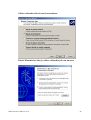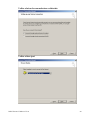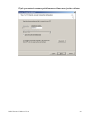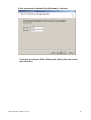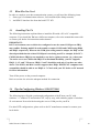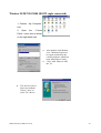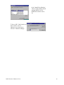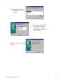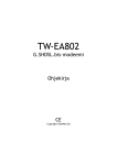
1
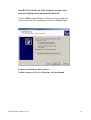
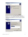
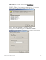
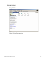
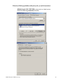
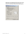
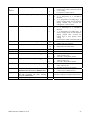
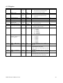
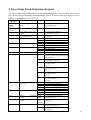
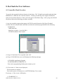
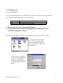
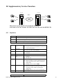
TeleWell ISDN TA TW-128 CI ohjeistus
Windows 95/98/NT4/2000, Linux ja Mac
Finish and English user manual
CE
ISDN TA128 CI Manual V.1.2
1
TeleWell ISDN -laitteiden käyttöehdot
Ohjekirjassa oletamme, että asiakas tuntee käytettävän käyttöjärjestelmän
perusteet.
Easytel Oy:n asiakastuki antaa neuvoja mikäli ISDN -laitteen asennus ei onnistu
tämän ohjeen kanssa. Asiakastukemme ei anna ohjeita mikäli asiakas ei ole lukenut
tätä TeleWell -ISDN -laitteen mukana tullutta suomenkielistä ohjetta.
Ensiasennustuki on avoinna arkisin klo 10-17 puh: 03-6101850
Muu tuki puh : 0600 92486 ark. 9-19 11,90 mk / min + normaalit puhelinkulut
Asiakastukemme ei kouluta modeemin, käyttöjärjestelmien, tietoliikenne- ja
Internetohjelmien käyttöä puhelimitse.
TeleWell ISDN -laitteiden asiakastuki antaa neuvoja vain tuotteiden
perusasetuksissa.
ISDN TA128 CI Manual V.1.2
2
Analogisten puhelinporttien ohjelmointi....................................................................... 7
AT komennot / AT Command .................................................................................... 53
Bios päivitys ja TA128CI............................................................................................ 31
Dynaaminen ISDN kanavien käyttö (Call bumping) .................................................. 29
Dynaaminen kanavan avaus ja sulku (BOD) .............................................................. 29
Kytkentä laitteeseen RS232 tai USB............................................................................ 10
Käyttöjärjestelmät ja niiden vaatimukset .................................................................... 12
Käyttöympäristön oletukset........................................................................................... 4
Laitekuvaus.................................................................................................................... 5
Linux............................................................................................................................ 16
Macintosh .................................................................................................................... 16
Merkkivalot ................................................................................................................. 11
Puhelinverkon PLUS –palvelut ..................................................................................... 7
Puhelun siirto sisäisesti toisen puhelinporttiin............................................................ 29
Saapuvan numeron näyttö ............................................................................................. 6
Saapuvannumeron näyttö asetetaan päälle komentosarjalla ......................................... 6
Tekniset standardit ........................................................................................................ 6
TeleWell TA 128CI asennus ja käyttöönotto.............................................................. 10
Windows 2000 ja Internet ........................................................................................... 17
Windows 3.11.............................................................................................................. 15
Windows 95 / 98 / NT 4/ 2000 modeemiajurin lisäys ................................................ 13
Windows 95/98/NT 4 ja Windows 2000 asennus ....................................................... 12
ISDN TA128 CI Manual V.1.2
3
Käyttöympäristön oletukset
Tuetut käyttöjärjestelmät;
Windows 95 a,b,c, Windows 98/98SE, Windows NT4 SP5 tai uudempi
Windows 2000 , Macintosh kaapelit ja ajurit hankittava erikseen
Linux ( KPPP -ohjelmalla suoraan TTY -porttiin, erillistä modeemiajuria ei
tarvita)
- ISDN NT1-verkkopääte asennettuna.
-1 vapaa S0-väylä verkkopäätteessä (NT1).
-2 analogista puhelinta tarvittaessa.
-1 vapaa RS232 -liityntä joka on vähintään 16550 UART COM1 tai COM2
tai 16650 UART jos käytetään 230.000 DTE nopeutta TeleWell HK-10 16650
HIGH SPEED kortti, jossa on 230K nopeusJos käytät TeleWell HK-10 16650
UART-korttia, poista COM 2 biosista ja aseta TW HK-1 COM 2 osoitteeseen
(IRQ4,COM2) ja nopeuskerroin x2(3.6) asentoon.
Mitään erillisiä COM -portin ajureita ei tarvita
Käytä ohjelmissa päätelaitenopeutta 115200 yhteensopivuussyistä
(nopeus on nyt 230 000).
tai
-USB -liityntä kun koneessa on Windows 98/2000 käyttöjärjestelmä
(Kun käytät USB -liityntää niin RS232 kaapeleita ei saa kytkeä)
-1 vapaa sähköliityntä ISDN sovittimen 230V AC DC 7V 1A. muuntajalle.
-TCP/IP ja PPP tuki käytettävässä tietokoneessa, jos kyseessä on Internet
yhteys/NT Server yhteys.
-Windows tai Mac-käyttöjärjestelmän perusteiden hallinta
puhelinverkkotoimintojen osalta.
-ISDN / MSN (omat puhelinnumerot käytettävissä) asennuksen aikana joista
2 ISDN numeroa puhelinporteille TEL-A/B ja 1 ISDN numero saapuville
Data-kutsuille tarvittaessa.
ISDN TA128 CI Manual V.1.2
4
Laitekuvaus
TeleWell ISDN TA 128 CI aktiivinen sovitin on tarkoitettu käytettäväksi
ISDN-puhelinverkossa S0-väylään (NT 1) kytkettynä. Laitetta käytetään
tietokoneen RS232 porttiin kytkettynä (UART vaatimus 16550 tai TW HK-1,
jossa 115200/230.000 bps modeemiporttinopeus tai USB porttiin kytkettynä
Windows 98/2000 ympäristössä.
RS232 ja USB portit eivät saa olla kytkettynä samanaikaisesti.
-Laitteessa on vakiona sisäiset PPP 64K ja MLPPP 128K yhteysprotokollat
Internet yhteyksille tai 2:n tietokoneen välisille yhteyksille, kun käytetään
TCP/IP protokollaa.
-Laite toimii tavallisen modeemin tapaan ISDN yhteyksille.
-Laite ei ole tarkoitettu yhteyksille analogisiin modeemeihin.
-Laitteessa on vakiona "FLASH BIOS" ohjelmallisille päivityksille.
HUOMAUTUS !
Oletuskoodia ei tule vaihtaa ilman maahantuojan suostumusta.
-Laitteessa on kaksi puhelinporttia: TEL A ja TEL B (analogiset)
on tarkoitettutavallisille puhelinlaitteille (ei ISDN puhelimille). Kyseisiin
portteihin kytketään fax,modeemi,puhelin.
-Laite tukee vain äänitaajuusvalintaisia laitteita (DTMF)
-Molemmissa analogisissaporteissa on oletuksena saapuvan numeron
näyttö ja niissä testatut puhelimet; Telematic Ilmo puhelin ”uusi
malli”,Doro mallistoja Doro ja Telematic -numeronnäyttölaitteet
Kytkettäviä laitteita voi olla vain 1 laite per TEL A tai TEL-B.
ISDN TA128 CI Manual V.1.2
5
Tekniset standardit
-HDLC,V.110, V.120, X.75, G3/fax RVS ohjelmalla Win95/98/NT 4:ssä.
-Laitteessa on vakiona sisäiset PPP 64K ja MLPPP 128K yhteysprotokollat
Internet yhteyksille tai 2:n tietokoneen välisille yhteyksille, kun käytetään
TCP/IP protokollaa.
Numeronnäyttö ( Caller ID )
TeleWell TA128 CI lähettää saapuvan numeron analogiselle laitteelle kun
keskus lähettää kutsujan numeron. Saapuva numero välitetään 1:n ja 2:n
hälytysäänen välissä sille puhelinportille jota kutsuttiin. Mikäli käyttäjä
ei odota vähintään 2 hälytystä niin saapuvaa numeroa ei näytetä.
Numeronnäyttö asetetaan päälle komentosarjalla
Nnumero informaatio ei välity puhelimille ellei puhelimen anneta hälyttää
vähintään 2 kertaa. Lisäksi puhelinyhtiön tulee välittää numerotieto
saapuvasta puhelusta. Puhelinkeskukset eivät välitä tietoa suojatuista
numeroista.
Mikäli samassa ISDN SO-väylässä on ISDN –puhelimia ja niihin vastataan 1:n
ja 2:n hälytyksen aikana niin puhelimesta voi kuulua lyhyesti analogisen portin
CALLER ID –tieto vaimeana äänenä. Toiminto ei sekoita ISDN –puhelinten
toimintaa.
TEL-A JA TEL-B porteille ja se tehdään vain kerran
Testatut puhelimt; Ilmo Phone (98/48 valmistettu) ja Doro X50 puhelimet
sekä Ilmo -numeronäyttölaite. Jos numeronnäyttölaitteen paristot eivät ole
kunnossa niin tieto ei välity tai jos puhelinyhtiö ei välitä tietoa.
AT$AC1<Enter> TEL-A-portti
AT$BC1<Enter> TEL-B-portti
AT$ED1<Enter> DTMF -koodaus päälle
AT$ER1<Enter> CID 1:n ja 2:n soiton välissä
AT$ES1<Enter> CID:n aloitus sekvenssi -AAT&W<Enter> Tallentaa asetuksen
CID= Saapuvannumeron näyttö toiminto
ISDN TA128 CI Manual V.1.2
6
Puhelinverkon PLUS -palvelut
Tämä toiminto on puhelinyhtiön tarjoama palvelu ja sitä käytetään seuraavasti.
Soiton siirto toiseen numeroon .
Nosta luuri ylös ja odota vapaa ääntä.
Näppäile > *21*numero# kuuntele keskuksen viesti.
Luuri alas.
Siirron peruutus #21#.
Plus -palvelut edellyttävät että ISDN numerot on ohjelmoitu analogisiin
portteihin.
Analogisten puhelinporttien ohjelmointi
Kytke tavallinen puhelin siihen porttiin jota ohjelmoit esimerkiksi TEL A.
a) Nosta puhelimenluuri ja odota valintaääntä
b) Paina näppäintä R/Flash (95ms katkos)
c) Näppäile **128 ja odota merkkiääntä
d) Näppäile 10*<numero>** ja odota merkkiääntä
e) Näppäile lopuksi #*# ja odota merkkiääntä ÆTiedot tallentuvat
Toista sama TEL -B portille TEL-B liittymän liittimen kautta
Analogisten puhelinporttien ohjelmointi Hyperterminal -ohjelmalla
1.
Käynnistä HyperTerminal -ohjelma (Käynnistä / Ohjelmat / Apuohjelmat
/HyperTerminal).
Jos HyperTerminal ei ole asennettuna koneelle, se on asennettava
Lisää/Poista sovelluksesta (Käynnistä / Asetukset / Ohjauspaneeli /
Lisää/Poista sovellus / Windows asennus / Tietoliikenneyhteydet /
Tarkenna / HyperTerminal / OK)
2.
Kaksoisklikkaa Hypertrm.exe kuvaketta.
3.
Kohtaan "Yhteyden kuvaus" anna haluamasi nimi yhteydelle
4.
Kohtaan "Yhdistä käyttäen" laita suoraan COM-porttiin x (katso kuva
alapuolella), jossa x = COM portin numero, johon TA128CI on
asennettuna.
ISDN TA128 CI Manual V.1.2
7
5.
Kohdassa "Ominaisuudet COMx" aseta COM portin nopeudeksi 38 400
bittiä sekunnissa. Muihin käy Windowsin oletuksena tarjoamat asetukset
(8, Ei mitään, 1, Laitteisto). Katso kuva seuraavalla sivulla. Lopuksi
hyväksy asetukset painamalla OK painiketta.
ISDN TA128 CI Manual V.1.2
8
6.
Seuraavaksi avautuu HyperTerminal ikkuna. Anna siellä komento AT&F
+
Enter. Jos antaa vastauksen OK, niin voit jatkaa eteenpäin. Huomaa, että
kirjoittamasi merkit eivät välttämättä tule näkyviin ruudulle.
7.
Anna komento AT$AN=puhelinnumero jonka haluat määritellä TEL A
portille. Vastaavasti TEL B portille saat määriteltyä numeron
komennolla AT$BN=puhelinnumero.
Dataportin MSN numeron saat määriteltyä komennolla
AT%n=msn-numero on puhelinyhtiön antama ISDN -numero.
8.
Tallenna vielä tekemäsi muutokset TA128 CI:n muistiin komennolla
AT&W<Enter>
ISDN TA128 CI Manual V.1.2
9
TeleWell TA 128 CI asennus ja käyttöönotto
Kytkentä laitteen RS232 tai USB porttiin
Sammuta kaikki toisiinsa kytkettävät laitteet jos RS232 -kytkentä
Molempia portteja ei saa käyttää samanaikaisesti
RS232
-Kytke TA 128 CI RS232 kaapeli tietokoneen vastaavaan RS232
liittimeen COM1 tai COM2.
-Jos RS232 kytkentä tulee Mac-tietokoneeseen, niin liitä Mac-kaapeli
(erikseen hankittava) mukana tulevan RS232-kaapelin jatkoksi, ja kytke
kaapeli Macin modeemiporttiin.
-Kytke mukana tuleva RJ45 ISDN-kaapeli ISDN-sovittimen ja ISDNverkkopäätteen välille.
-Kytke sähkömuuntaja laitteen sähköliittimeen DC 7V 1A (tarkista muuntajan
päältä oikeat tiedot jännitteistä)
-Kytke TEL A ja TEL-B portteihin tarvittavat analogiset laitteet
-Paristokoteloon asennetaan tarvittaessa 6 KPL vuotamattamia AA -paristoja
(paristojen maksimi käyttöaika on maksimissaan 1 tunti kaikille toiminnoille)
-Terminaattorikytkin on paristokotelossa ja sen asentoa ei tarvitse muuttaa
ellei ole teknisiä ongelmia S0 -väylässä)
USB
Jos käytät USB -porttia niin kytke sähkömuuntaja ja ISDN -kaapeli ensin
laitteeseen ja sitten vasta USB -kaapeli koneen ja TA128 CI:n välille
USB portin käyttö on kohdassa Windows 98/2000 USB käyttö.
ISDN TA128 CI Manual V.1.2
10
Merkkivalot
Power
>
Vihreä valo osoittaa että laite on kunnossa
Connect >
Vihreä merkkivalo ;Puhe tai Data yhteys päällä
Punainen merkkivalo; Molemmat ISDN kanavat
käytössä ML PPP 128 internet yhteys
TX/RX >
Vihreä merkkivalo vilkkuu
Tiedon lähetys tai vastaanotto menossa
LINE >
Vihreä merkkivalo
Laite on kytkeytyneenä S0 -väylään
ISDN TA128 CI Manual V.1.2
11
Käyttöjärjestelmät ja niiden erityisvaatimukset
Windows 95/98/NT 4 ja Windows 2000 asennus
Aktiivinen ISDN sovitin TeleWell TA 128CI asennetaan kuin tavallinen
modeemi ja ulkoisen modeemin / ISDN -laitteen asennusohje on
Windows käyttöjärjestelmässä.
Yhteyden muodostukseen käytetään Puhelinverkkoyhteydet toimintoa.
Modeemiajuri ja USB -ajurit ovat samalla asennuslevyllä.
CAPI protokollia ei käytetä ei tueta. Laite toimii AT -komennoilla
Asennuslevy A:
\WIN2000 > Windows 2000 USB ajurit USB to COM -port
\WIN98 > Windows 98 USB -ajurit USB to COM -port
A:\GENERAL.INF -modeemiajuri Windows 95/98/NT4/2000
Tarkista, että olet asentanut Windowsin seuraavat osat:
puhelinverkkosovitin, TCP/IP, Microsoft verkkojen asiakas. Windows
95:n versio pitää olla vähintään 4.00.950a (Tarkista:
ohjainpaneeli/järjestelmä)
Huomautus Windows NT 4
Windows NT:ssä REMOTE ACCESS SERVICE tulee asentaa ensin.
Ja tarvittaessa lisätä modeemiajuri sen asennuksen aikana kohdassa
(Install Modem). PPP/LCP ei saa olla käytössä ja IP-Header
Compressio ei saa olla päällä käytettäessä kahta kanavaa. SP 5 tulee
olla asennettuna.
Huomautus Windows 2000
PPP/LCP ei saa olla käytössä, jos käytetään kahta kanavaa. IP-Header
Compressio ei saa olla päällä käytettäessä kahta kanavaa.
ISDN TA128 CI Manual V.1.2
12
Windows 95 a,b / 98 /98SE / NT 4/ 2000 modeemiajurin lisäys
RS232 kytkentä
Siirry kohtaan Ohjainpaneeli/Modeemit
/Lisää/Älä tunnista/Anna Levy A:/Valitse listalta haluttu ajuri vaihtoehto ja
kuittaa OK.
Internet käyttöön valitaan joko PPP 64K tai ML PPP 128K halutun
nopeuden mukaan
> TW ISDN-TA (PPP-64K) Internet 64 yhteys (2:n puhekanava vapaana).
TW ISDN-TA (Soft-Fax)" Ohjelmallinen G3 faksi RVS.COM-ohjelmalla.
TW ISDN-TA (X.75)" X.75 protokolla BBS järjestelmiin.
> TW ISDN-TA (MLPPP-128K) Internet 128k nopeus
(IP-Header Compressio ei saa olla päällä käytettäessä kahta kanavaa ML PPP
ajuri).
Valitse oikean COM portti ajurille ja kuittaa OK valinnalla. Valitse
lopuksi valmis ja käynnistä kone.
Internet yhteys muodostetaan Puhelinverkkoyhteydet alueen kautta jossa
valitaan TeleWell ISDN TA 128 CI malli
ISDN TA128 CI Manual V.1.2
13
Windows 98 / 98SE / 2000 modeemiajurin lisäys
USB -kytkentä
-Kytke USB -kaapeli laitteen ja koneen välille.
(sähkömuuntaja liitettynä laitteeseen)
-Windows -tunnistaa laitteen ja pyytää ajureita
-Aseta ajurilevy A:asemaan ja määrittele Windows etsimään
ajuria A: asemasta seuraavista hakemistoista.
\WIN2000 > Windows 2000 USB ajurit > USB to COM -port
\WIN98 > Windows 98 USB –ajurit > USB to COM -port
-Windows lisää USB -ajurit ja tekee virtuaalisen COM -portin
TA128CI -laitteelle.
-Käynnistä kone ja asenna varsinainen modeemiajuri kuten asensit modeemin
edellisessä kohdassa mutta valitse COM -portikse uusi virtuaalinen COM portti ja nopeudeksi sen maksimi COM3 tai se portti jonne Windows muodosti
virtuaalisen COM portin.
Internet yhteys muodostetaan Puhelinverkkoyhteydet alueen kautta
jossa valitaan TeleWell ISDN TA 128 CI malli
Jäljempänä malli Windows 2000 yhteydestä Internetiin
ISDN TA128 CI Manual V.1.2
14
Windows 3.11
RS232 kytkentä
Käytetään Internet Explorer 3.0a tai uudempi versio, jossa TCP/IP ja soittoohjelma asennettuna.
Modeemityypin valinta: Explorer-ohjelmassa valitaan standard 28800
modeemi.
Muuta kyseistä ajuria seuraavasti: Connection Properties/Change modem/Do
not detect/Valitse/Motorola/ISDN TA 210. Tämän jälkeen poistu ja muuta
Modems2.ini-tiedostossa oleva rivi Init String: Jos asetat AT%A2=6&k3 niin
yhteys nopeudeksi tulee 128K. Jos asetat AT%A2=5&k3 niin yhteys on 64K.
ISDN TA128 CI Manual V.1.2
15
Macintosh
RS232 liityntä (USB –ajurit tulevat mahdollisesti myöhemmin kesällä 2000)
Käytä FREE PPP ohjelmaa 2.6 tai OPEN PPP ajureita www.easytel.fi ISDN ohjelmistot alueella. DTE nopeus 115200bps, RTS/CTS -vuonohjaus.
Ajurin löydät osoitteesta http://www.eunet.fi/tucows (Mac alueelta/TCP/).
Alustus komento: AT!C0=4W0X4%A2=6 128K yhteys tai AT!C0=4W0X4%A2=5
64K yhteys.
Linux
RS232 liityntä
Käytä suoraan TTY porttia jossa ISDN -laite on, DTE 115200,8,n,1 ,
RTS/CTS päälle.Käytä DTE speed kohdassa 230.000 jos laitteesi tukee
kyseistä nopeutta.
AT&F%A2=5<Enter> > 64K,
AT&F%A2=6<Enter> > 128k
ISDN TA128 CI Manual V.1.2
16
Windows 2000 ja Internet
Asenna Windows 2000 niin, että TA128 CI ei ole kytkettynä tietokoneeseen. Sammuta kone ja kytke TA128 CI haluttuun modeemiporttiin (RS232 COM1 tai COM2). Jos käytät USB -porttia niin
konetta ei tarvitse sammuttaa. Käynnistä Windows 2000 uudelleen
arvittaessa.
RS232 -kytkentä
Jos Windows 2000 ilmoittaa että uusi modeemi löydetty niin hyväksy
valinnaksi modeemin tyyppi ”Unknown model” ja valitse kohta
”Change/Muuta” ja valitse asennuslevyltä uusi ajuri TA 128 PPP
64K RS232 -kytkentä.
USB -kytkentä
Windows 2000 ilmoittaa että uusi USB laite löydetty. Anna ajureiden
asennuspoluksi A: levyasema. Aseta TeleWell ajurilevyke A: asemaan
ensin ja hyväksy valinta. USB -käytössä Windows 2000 asentaa USB portin ja USB-serial conversion -ajurit ja muodostaa virtuaalisen COMx portin TA 128 CI -mallille.
ISDN TA128 CI Manual V.1.2
17
Kun RS232 kytkentä tai USB -kytkentä on tehty siirry
kohtaan Ohjainpaneeli/modeemit/Lisää(Add)
Valitse ADD ja anna Windows 2000:n etsiä uusi modeemi
Aseta seuraavan kuvan mukainen valinta ja Valitse Next
Poista rasti kohdasta Don’t detect …
Valitse Seuraava/Next ja Windows etsii modeemin
ISDN TA128 CI Manual V.1.2
18
Kun TA128 CI on löydetty tulee näytölle vaihtoehto ”Unknown
modem” valitse vaihtoehto Change ja valitse Have a disk/Anna levy
vaihtoehto ja aseta asennuslevy A: -asemaan ja kuittaa A: valinta OK
näppäimellä.
Valitse listalta haluttu ajuri
ISDN TA128 CI Manual V.1.2
19
PPP-64k ajuri on 64K nopeuksinen SUOSITUS
ML PPP-128K on 2 kanavan ajuri ja nopeus on 128K (2:n kertainen
puhelinmaksu) (Täysi teho edellyttää 16650 Uart korttia)
Kuittaa valinta OK -näppäimellä ja valitse Next / Finnish
Tarkista nopeusasetus maximum port speed (Pitää olla 115200)
ML PPP-128K ajuri asettaa 230.000 mutta se ei toimi kaikissa koneissa.
ISDN TA128 CI Manual V.1.2
20
Internet yhteys
Siirry kohtaan
Valitse Make a New connection
ISDN TA128 CI Manual V.1.2
21
Valitse vaihtoehto alla olevan kuvan mukaan
Käytä Wizardia hyväksi ja valitse vaihtoehto joka on kuvassa
ISDN TA128 CI Manual V.1.2
22
Valitse oheisen kuvan mukainen vaihtoehto
Valitse oikea ajuri
ISDN TA128 CI Manual V.1.2
23
Täytä operaattorin antama puhelinnumero ilman maa ja alue valintaa
ISDN TA128 CI Manual V.1.2
24
Lisää operaattorisi antama käyttäjätunnus ja salasana
Täydennä tarvittaessa Mail (sähköpostin tiedot jotka olet saanut
operaattorilta)
ISDN TA128 CI Manual V.1.2
25
Mikäli et halua suoraan internet yhteyttä, niin poista yllä oleva valinta ja
kuittaa FINISH -painikkeella
ISDN TA128 CI Manual V.1.2
26
Windows 2000 ja puhelinverkkoyhteydet ja sen lisäasetukset
Mikäli käytät ML PPP128K ajuria niin tee tämä asetus
Soittokuvakkeen proberties alueella
ISDN TA128 CI Manual V.1.2
27
Mikäli tämä asetus on päällä niin ML PPP 128K nopeus on hidas.
Tässä ruudussa määrittelet milloin yhteys lopetetaan jos ei ole
liikennettä. Asetusta muutat kohdassa Idle time before hang UP
ISDN TA128 CI Manual V.1.2
28
Dynaaminen ISDN kanavien käyttö (Call bumping)
Soita puhlimella tai vastaa puheluun kun käytät Internet 128K ( ML
PPP) yhteyttä. Toiminto on käytettävissä jos seuraavat oletukset
toteutuvat.
-Puhelinyhtiö on kytkenyt koputuksen päälle
-ISDN –kotivastaaja ei ole samassa liittymässä
ATU1%A2=6 komento on annettu (oletuksena biossissa)
-Analogisten porttien numerot on määritelty
Dynaaminen kanavan avaus ja sulku (BOD)
AT –komennolla AT%A2=6U1S107=5
TA 128CI avaa ja sulkee toisen ISDN kanavista kapasitettin nousun
ja laskun tarpeen mukaan.
Katso AT –komennot alueelta S107 komennon arvot
TeleWell TA 128 CI ohjelmallinen nollaus (resetointi)
Tarvittaessa voit alustaa laitteen aivan kuten
poistaisit sähkön hetkeksi laitteesta.
AT%Z1 <Enter> Laite vastaa OK ja toiminto kestää n 4 sekuntia.
Tämä alustus ei poista puhelinnumeroita mutta tyhjää laitteen kaikki
muistit jos sinne on jäänyt jotain tietoa edellisestä yhteydestä.
Puhelun siirto sisäisesti toisen puhelinporttiin
Vastaa puheluun ja paina R/flash -näppäintä
näppäile 2 **0 ja toinen vapaa puhelinportti hälyttää.
Sulje puhelin josta siirsit.
ISDN TA128 CI Manual V.1.2
29
TA 128 CI ja biospäivitys
Tämä toiminto voidaan suorittaa vain jos Easytel Oy:n asiakastuki antaa
siihen luvan. Mikäli päivitys tehdään ilman lupaa niin takuun katsotaan
raukeavan välittömästi .
TA128/TA128A tai TA128+Nt1 koodit eivät sovellu tälle mallille.
1. Käynnistä HyperTerminal ohjelma (Käynnistä / Ohjelmat / Apuohjelmat /
HyperTerminal). Jos HyperTerminal ei ole asennettuna koneelle, se on
asennettava Lisää/Poista sovelluksesta (Käynnistä / Asetukset / Ohjauspaneeli
/ Lisää/Poista sovellus / Windows asennus / Tietoliikenneyhteydet / Tarkenna
/ HyperTerminal / OK)
2. Kaksoisklikkaa Hypertrm.exe kuvaketta.
3. Kohtaan Yhteyden kuvaus anna haluamasi nimi yhteydelle
4. Kohtaan "Yhdistä käyttäen" laita suoraan COM-porttiin x (katso kuva
alapuolella), jossa x = COM portin numero, johon TA128CI on
asennettuna.
5. Kohdassa "Ominaisuudet COMx" aseta COM portin nopeudeksi 38 400
bittiä sekunnissa. Muihin käy Windowsin oletuksena tarjoamat asetukset (8, Ei
ISDN TA128 CI Manual V.1.2
30
mitään, 1, Laitteisto). Katso kuva alla. Lopuksi hyväksy asetukset
painamalla OK painiketta.
5. Seuraavaksi avautuu HyperTerminal ikkuna. Anna siellä komento at +
Enter. Jos tulee vastaus OK, niin laite on todennäköisesti valmis bios
päivitykseen.
6. Poista TA128CI:n takaa kaikki verkkojohdot (Tel-A, Tel-B, S/T -line) ja
jätä kiinni pelkästään tietokoneeseen yhdistetty RS232 kaapeli kiinni.
7. Aloita Bios -päivitys komennolla AT%FAPPS
8. Ruudulle tulee seuraava teksti:
AT%FAPPS Application Upgrade
FLASH PROGRAM VERSION 1.x
Erase and reprogramme flash eprom contents (y/n)
10. Vastaa y + Enter
11. Seuraavaksi ruudulle tulee seuraavanlainen ilmoitus:
*** WARNING ***
ISDN TA128 CI Manual V.1.2
31
Erasing Flash Memory
Flash eprom upgrade procedure
Ready for ASCII download
CTS (hardware) flow control
38400, 8, N, 1
>
12. Valitse valikosta Siirrä / Lähetä tekstitiedosto ja valitse
imuroimasi/purkamasi biosversio.
13. Ruudulla lähtee juoksemaan seuraavankaltainen kuvio:
>>>>>>>><<<<<<<<
..jolloin bios -päivitys on käynnissä. Tämä saattaa kestää jopa 20 min,
joten ei kannata olla kärsimätön, jos ei heti tapahdu mitään.
14. Kun Bios -päivitys on valmis, tulee ruudulle seuraavanlainen ilmoitus:
Code Update Successful
15. Kun bios -päivitys on tehty onnistuneesti, sulje HyperTerminal -ohjelma,
ja poista TA128CI:stä virrat 5:ksi sekunniksi.
16. Kytke TA128CI:n virrat ja koeta HyperTerminalissa onko bios -päivitys
onnistunut seuraavilla komennoilla:
At + enter Jos tulee OK, niin jatka seuraavalla komennolla:
Ati3 Jos vastaa tähän uuden bios -versionumeron, niin bios päivityson
onnistunut
ISDN TA128 CI Manual V.1.2
32
ISDN TA128 CI Manual V.1.2
33
TeleWell ISDN
TA128CI
User‘ s Manual
ISDN TA128 CI Manual V.1.2
34
ISDN TA128 CI User’s Manual
1.
INTRODUCTION ............................................................................................................................... 37
2.
FEATURES……………………………………………………………………………….5
3.
OUTLET DESCRIPTION .................................................................................................................. 39
3.1
FRONT PANEL ..................................................................................................................................................... 39
3.2 REAR PANEL CONNECTION ..................................................................................................................................... 40
3.3 SIDE PANEL ............................................................................................................................................................. 40
4 CONNECTION METHOD ............................................................................................... 41
4.1 CONNECTION PROCEDURES .................................................................................................................................... 41
4.2 CONNECTION WITH TELEPHONE/FAX .................................................................................................................. 41
4.3 CONNECTION WITH PC........................................................................................................................................... 41
4.4 CONNECTION WITH MODEM ................................................................................................................................... 42
4.5 MULTI-DROP CONNECTION................................................................................................................................... 42
4.6 CONNECTION NOTIFICATION................................................................................................................................... 42
5.1 PACKING LIST ......................................................................................................................................................... 42
5.2 WHAT ELSE YOU NEED ........................................................................................................................................ 43
5.3
INSTALLING THE TA .......................................................................................................................................... 43
5.4 TIPS ON CONFIGURING WINDOWS 95/98/NT/2000/LINUX .................................................................................. 43
5.5 TIPS ON CONFIGURING YOUR DIAL-UP NETWORK................................................................................................... 48
5.6
VERIFYING YOUR CONNECTION ......................................................................................................................... 50
6. AT COMMAND.............................................................................................................................. 51
6.1 DESCRIPTION OF AT COMMAND ............................................................................................................................. 51
6.1.1 AT Command ..................................................................................................................................... 51
6.2 AT COMMAND ......................................................................................................................................................... 52
6.2.1 AT Command Overview ............................................................................................................... 52
6.2.2 AT Command List ............................................................................................................................ 54
6.3 S REGISTER.............................................................................................................................................................. 58
6.4 RESULT CODE ......................................................................................................................................................... 59
7. EASY SETUP FROM TELEPHONE KEYPAD ................................. 60
7.1 ENTERING PROGRAMMING MODE ............................................................................................................................ 61
7.2 SETUP CONFIGURATION ........................................................................................................................................... 61
ISDN TA128 CI Manual V.1.2
35
7.3 STORING THE SETTING ............................................................................................................................................ 61
8. RE-FLASH THE NEW SOFTWARE ................................................................ 62
8.1 NORMAL RE-FLASH PROCEDURE ............................................................................................................................. 62
8.2 FAILED RE-FLASH PROCEDURE ............................................................................................................................... 64
9 TROUBLE SHOOTING ....................................................................................................... 65
POWER SWITCH ON BUT PW LED IS NOT LIT. ............................................................................................................... 65
TYPE “AT’, BUT THE TA DOES NOT RESPOND WITH “OK’ MESSAGE ............................................................................. 66
USING ATD TO CALL, BUT “NO CARRIER” IS DISPLAYED........................................................................................... 67
CAN NOT ACCEPT INCOMING DATA CALL ..................................................................................................................... 68
UNABLE TO ACCEPT INCOMING VOICE CALLCAN NOT USE CALL WAITING................................................................. 69
CAN NOT USE CALL WAITING ...................................................................................................................................... 70
9.1 SELF DIAGNOSTICS ................................................................................................................................................. 71
10. SUPPLEMENTARY SERVICE FUNCTION...................................... 73
APPENDIX ..................................................................................................................................................... 77
APPENDIX 1 DCE 9PIN D TYPE CONNECTOR DEFINITION ......................................................................................... 77
APPENDIX 2 DISCONNECT CAUSE INDICATION .......................................................................................................... 78
APPENDIX 3 SPECIFICATION ...................................................................................................................................... 79
ISDN TA128 CI Manual V.1.2
36
1. Introduction
The ISDN TA (Integrated Service Digital Network Terminal Adapter) is a communication product
for the Internet and digital communication era. It provides high speed and high quality
transmission. The TA supports two analogs and one digital port. The two analog ports act like two
regular telephone lines, which can be connected to regular telephone, answering machine, fax and
modem products. Also, the TA can provide flexible functions like: supplementary service, call
screening, speed dial and global call function to meet user’ s requirements. The digital port with
the RS232 link can be connected to PC to support data communication with remote site. It supports
many protocol selection such as V.110, V.120, X.75, X.25 on D channel, PPP (Point-to-Point
Protocol), MLPPP (Multi-Link PPP), BACP (Bandwidth Allocation Control Protocol) / BOD
(Bandwidth On Demand) function. With the MLPPP, the entire 128k ISDN bandwidth can be used
to access the Internet. The BOD function can utilize dynamic bandwidth demand under MLPPP
connection. Under MLPPP data connection, the TA will automatically release one B channel for
voice communication when the user picks up the phone to make a call and returns to two B
channels for MLPPP when the phone hangs up. With the BACP function, the 128k capacity of
ISDN can be utilized fully. The TA is equipped with channel bundling feature which allows the user
to use both B channels to maximize the 128k bandwidth for data transmission.
The TA complies with ITU-T Q.921, Q.931 for D channel protocol, and provides switching type
selections for different countries. Following are the switch types supported by the TA:
*Euro-ISDN EDSS1
The TA is equipped with flash EPROM for easy future software upgrade through RS232 port.
ISDN TA128 CI Manual V.1.2
37
2. Features
•
•
Async-to-Sync PPP conversion
Support MLPPP to utilize the full 128k ISDN capacity
•
•
•
•
•
Support BACP/BOD for dynamic bandwidth demand
Up to 230.4k DTE speed
One standard RJ11 modular jack for U interface
Selectable terminating resistance (100 Ohm) inside battery pack
1 standard RJ45 modular jack for S/T interface to NT1 (EURO ISDN)
•
Two analog ports with RJ11 modular jack with CALLER ID
•
•
•
•
•
•
One RS232 data port with DB9-Sub male connector
One USB -port for Windows 98 and Windows 2000
LED indication
Inner Communication
Receive Priority, Call Screen, Speed Dialing function
ITU-T V.110, V.120, X.75, X.25 on D protocol
•
•
•
•
•
•
Channel bundling function
Switching type selection
Hardware CTS/RTS, Software Xon/Xoff Flow Control
Network supplementary service
Local supplementary service
Easy setup from telephone keypad for analog phones
ISDN TA128 CI Manual V.1.2
38
3. Outlet Description
3.1 Front Panel
1. PW - Power on/off
2. Connect - Green TA connected to the network RED when ML PPP
3. DTR - ON terminal connected to TA via DTE or USB
4. TX/RX - Data send or receive
5. LINE - Devie connected to S0 bus
ISDN TA128 CI Manual V.1.2
39
3.2 Rear Panel Connection
1. DTE DB9-SUB male connector RS232 or USB
Connect to PC or DTE equipment. USB only with Windows 98 and 2000
2. Analog Port TEL-A, TEL-B
Connect to the regular telephone, answering machine or fax machine.
3. AC Power plug
Connect to DC 7V adapter
4. ST
ST interface connection. you can connect other ISDN TA phone with S/T interface to make a
multi-drop bus connection.
5. FG, Frame Ground
Optional and not connected in this model
3.3 Side panel
Battery Backup
In case of sudden loss of local power, the TA has a battery power backup solution. A total of 6 AA
batteries are required to backup the TA. Please make sure all 6 batteries are placed correctly.
Battery Mode Operation
In case of sudden loss of local power, the TA will switch to battery backup mode automatically. ( If
all 6 batteries had been installed properly.) Under the battery backup mode, all 3 data and analog
ports can be operated normally.
In battery backup mode, with average brand new batteries, the TA can last at least 6 hours in
standby or it can run one analog port continuously for about 1 hours.
Changing Batteries
Please inspect batteries if the TA does not work properly under battery backup mode. If the battery
is low, please replace batteries. We suggest the user to replace all 6 batteries together.
ISDN TA128 CI Manual V.1.2
40
4 Connection Method
4.1 Connection Procedures
1.
2.
3.
4.
5.
Plug in AC power adapter DC 7V 1A
Connect the ST interface RJ45 modular jack to ISDN port with the RJ45 cable.
Connect RS232 cable between TA and PC or TA and USB put not both.
Plug in the regular telephone to analog port A or B with RJ11 cable.
Connect other ST ISDN phone or TA device with RJ45 cable
A. With this connection method user can use V110, V120, X.75, X.25 protocol to
communicate with other TA.
B. Use PPP or MLPPP to connect with ISP (Internet Service Provider) for Internet access.
C. Use regular telephone make calls
D. Use inner communication between analog port TEL-A and TEL-B.
4.2 Connection With Telephone/Fax
•
•
Locate an available RJ11 modular jack telephone outlet.
Take one end of the modular cord supplied with the TA and plug it into the analog port
TEL-A or TEL-B modular jack on the back of the TA.
•
Plug the other end of the modular cord into the modular jack on the regular telephone/fax.
4.3 Connection With PC
•
Use the attached RS232 cable to connect TA‘ s DTE port and PC’ s RS232 port or use
USB port with Windows 98/2000
•
If the connector type of PC‘ s RS232 port does not match, you may need to use the 9-to-25
gender changer to connect between the RS232 cable and PC
ISDN TA128 CI Manual V.1.2
41
4.4 Connection With Modem
•
Connect the telephone to modem‘ s port labeled with PHONE then connect modem‘ s
LINE port to TA’ s TEL A or TEL B port
4.5 Multi-Drop Connection
To make a multi-drop bus connection, you can connect the two TAs by the RJ45 cable
4.6 Connection Notification
Do not connect two or more telephones on the same port. It will affect the Impedance of the telephone
set.
5 Installing The TA
5.1 Packing List
Unpack your TA and make sure that you have the following items:
♦
♦
♦
♦
♦
♦
TA main unit
Female RS232 cable and USB caple
Power adapter 230 V ac DC 7V 1
S/T interface cable
User‘s manual
Windows driver disk
When you opened your package, make sure that all of the above items are included in good
order. If any of the components were damaged, please contact your dealer immediately.
ISDN TA128 CI Manual V.1.2
42
5.2
What Else You Need
In order to complete your data communication system, you will need the following items:
1. Some type of communication software, if not included (like dialup network).
2. An ISDN U-interface line from the local PTT NT1
5.3
Installing The TA
The following instruction explained how to install the TA with a PC or PC compatible
computer. If you install the TA into a different computer, refer to the manual that came with
or contact your dealer for instructions and assistance.
IMPORTANT:
In PC environment, two serial devices configured to use the same COM port or IRQ
may conflict. Existing multi-I/O cards usually occupies COM1 and COM2 using IRQ4
and IRQ3 respectively. Whereas the COM port setting must be unique, the IRQ can be
shared provided that the related COM port is not being used. For example, if the PC’s
COM2 which uses IRQ3 is not attached to any device (print or mouse, etc.), then your
TA can be set to use COM4 with IRQ3. For maximum flexibility, your PC supports
IRQ2, 3, 4, 5, and 7. However, IRQ2, 5 and 7 should be used only if you have no other
choice. Not all PCs and DOS versions support these IRQs. IBM PC/AT computers and
compatibles should be able to use IRQ5 or 7. Check with your PC dealer or PC manual
for more information.
Turn off the power on the personal computer.
Refer to section 4 to select the adequate method for connection.
5.4 Tips On Configuring Windows 95/98/NT/2000
The following tips will guide you through configuration of the TA on your PC with
windows 3.1, windows 95 and windows NT, step by step, with windows graphs of windows
95 environment. Proceed with choosing the correct COM port for your TA.
For other DTE configurations, please refer to the PC manufacturer manual or contact your
local dealer.
ISDN TA128 CI Manual V.1.2
43
Window 95/98/NT4/2000 (RS232 caple connected)
1. Choose ‘My Computer’
icon.
2.
Open
the
‘Control
Panel’ menu box as shown
on the right hand side.
3.
4.
5.
After double click Modem
icon, ’Modems Properties’
box appear and show the
existing modems which has
been installed previously.
Click ‘Add’ button to add
the TA.
Tick the box (Don’t
detect my modem)
Choose “next” to
select TA’s driver.
ISDN TA128 CI Manual V.1.2
44
6. In ‘Install New Modem’,
click on ‘Have Disk’ button
and put ISDN TA CDROM driver disk to drive
D:
7. Press ‘OK’ if the location of
driver disk is correct.
Otherwise you may press
‘Browse’ button to change.
ISDN TA128 CI Manual V.1.2
45
8. Select the modem to be
installed. Click ‘Next’ to
continue.
9. Choose an available COM
port which is available
(It should not conflict
other devices) and click
‘Next’ button.
10. Press ‘finish’ to complete
setup.
ISDN TA128 CI Manual V.1.2
46
Windows 98/2000 and USB
1.
2.
Power Plug into power plug and wait 5 seconds and the plug USB cable
into USB connector of PC and TA128CI.
Windows will recognise the new USB device and will ask drivers for for new
USB device. Correct path is is Floppy A:. So define search path so that you
specify the installation drivers path A:\.
3.
After USB -drivers installed just add the modem driver into system as
you installed in previous section and select the COM -port which was
created By USB to Serial driver installation.
4.
Power adapter is needed when USB -connector in use because of
analogports ringing signals
Linux operating systems with RS 232
1.
2.
3.
4.
5.
6.
7.
Use KPPP program and directly TTY port where TA is installed
Or any similar
Set port 230.000 or 115200 dte speed 8,N,1
CTS/RTS setting ON
PPP / 64K connection AT%A2=5
ML PPP 128K AT%2=6
In this case do not use IP -header compression
If device is not working the slow down AT -command sending speed and
response wait time.
ISDN TA128 CI Manual V.1.2
47
5.5 Tips on configuring your Dial-Up Network
After you setup the ISDN TA driver completely. The next step is going to have your Dial-Up
network working. Following tips will guide you how to configure your Dial-Up Network
with Windows 95/98/2000
Choose Dial-Up Network
icon from ‘My Computer’
window.
1.
2.
Click the ‘Make New
Connector’ icon
twice to create a connection.
3.
Choose a protocol for
ISDN TA and give a
name for this connection
and press ‘Next’ button.
Note! If you use ML PPP 128K driver then TCP/IP header compression has to be off
And DNS -values has to be set up correctly in TCP/IP proberties.
ISDN TA128 CI Manual V.1.2
48
4.
5.
Enter the correct
country, area code
and phone number
(The phone number
depends on the ISP
you selected) Then
press ‘Next’.IF asked
Reconfirm the New
connection and press
Finish button.
6. The new connection of
ML-PPP has been
completed and a new icon
will appear. You may
make future modifications
by checking the contents
of function.
ISDN TA128 CI Manual V.1.2
49
5.6
Verifying Your Connection
Start a communication program (Hyperterminal) and place the computer in terminal mode.
Refer to your computer manual to find out the appropriate commands to do so.
Follow these procedures to verify your installation:
1. Type
AT[Enter]
If your system is operating properly, TA will response with an ‘OK’ message to your
screen and waits for the next command.
2.
Use your communication software to prepare your computer to dial a data call.
For example, you can test the data connection under V.110 protocol with the following
procedures.
AT%A2 = 1 ; Select V.110 communication protocol.
ATD 5552121 ; Where 5552121 is the called party’s telephone number with V.110
protocol setting.
After ATD5552121 you can see the B1 or B2 LED is lighted and then, the ‘CONNECT’ or
‘NO CARRIER’ message will be displayed.
CONNECT ; Means TA connected with the Called Party.
NO CARRIER; Means TA did not connect with the Called Party, may be due to
Called Party busy.
ISDN TA128 CI Manual V.1.2
50
6. AT COMMAND
6.1 Description of AT Command
Hayes command set is a standard for Hayes modem commands for its Smartmodem 300. Most
modem manufactures adopted this command set in order to have Hayes compatible. The command
set used by the Smartmodem 300, as well as most modems or TAs today (with a few additional new
advanced commands), is known as the AT command set. AT stands for attention, and is placed in
front of actual content of command so that the TA knows what follows is an command directed at
the modem or TA. With the exception of some “A/” and “+++” command, “AT” command is the
process to place command to the TA.
Different modems or TA’s may have slightly different command sets, but generally speaking, most
of the TAs follow the standard set by Hayes.
6.1.1 AT Command
When you connect terminal equipment (like PC) with the TA, after typing AT command ending
with [ENTER] key, TA will process the command and then return the result code to the terminal
equipment. Each AT command must starts with “AT” and end with [ENTER] key (with the
exception of “A/” and “+++” commands).
Command Format
The following is the format of AT command:
AT
command
value
command
value
CR
LF
Result code has two styles (Verbose and Numeric). The following are their formats:
CR
LF
Result code(Verbose)
Result code(Numeric)
CR
CR
LF
S register
The S register is used to store the settings including
auto answer mode
escape sequence character
V.110 connect speed .....
etc.
ISDN TA128 CI Manual V.1.2
51
If you want to change the value of S register, you can use the ATS command.
6.2 AT Command
6.2.1 AT Command Overview
Command
ATA
ATD
ATEn
ATH
ATIn
ATL
ATO
ATQn
ATSn=x
ATVn
ATWn
ATXn
ATZn
AT&Cn
AT&Dn
AT&F
AT&Kn
AT&Sn
AT&Vn
AT&Wn
AT&Yn
AT%A2=n
AT%A5=n
AT%D
AT%DC
AT%FAPPS
Description
Manual answer
Dialing
Echo command
Hang up
Interrogate the TA product status
Dialing the latest number
Return to on line state
Return result codes select
Set S register
Verbose mode
Connection message format select
Result code set select
Reset recall user profile
CD signal control
ER signal control
Recall factory default setting
Flow control
DR signal control
Display system configuration
Write user profile
Load user configuration when power on
Data port protocol selection Default is PPP 64K
Set enbloc or overlap sending mode when dialing telephone number
Data port setting display
Show disconnect cause, source, charge
Re-Flash the new software
AT%N=x
AT%Sn
AT%Z1
Set data port directory number / sub-address
Data port call screen function enable
Software reset
AT$AAn
AT$AN=x
AT$AOn
AT$APn
AT$ASn
AT$BAn
AT$BN=x
AT$BOn
AT$BPn
AT$BSn
AT$CC
AT$CD
AT$CGn
AT$CIn
AT$CPn
AT$CSn
Set analog port A voice information capability in answer mode
Set analog port A directory number / sub-address
Set analog port A voice information capability in originate mode
Dial pause set up for analog port A
Screen incoming call for analog port A
Set analog port B voice information capability in answer mode
Set analog port B directory number / sub-address
Set analog port B voice information capability in originate mode
Dial pause set up for analog port B
Screen incoming call for analog port B
Display advice of accumulate charge
Display all analog port setting
Global call select setting
Enable inner communication
Receiver priority setting
Select supplementary service function
ISDN TA128 CI Manual V.1.2
Default
ATE1
ATQ0
ATV1
ATW0
ATX0
AT&C1
AT&D2
AT&K3
AT%S0
AT&Y0
AT%A2=5
AT%A5=0
AT%S1
AT$AA2
AT$AO0
AT$AP1
AT$AS1
AT$BA2
AT$BO0
AT$BP1
AT$BS1
AT$CG2
AT$CI1
AT$CP1
AT$CS1
52
AT$CZn
AT$CFn
AT*CFAn
AT*CFBn
AT*CFGn
AT*CFA=
AT*CFB=
AT*CFG=
AT$EUn
AT$ESN
AT$ERN
Initialize charge
Call forwarding function select
Enable call forwarding for analog port A
Enable call forwarding for analog port B
Enable call forwarding under global call
Set call forwarding number for analog port A
Set call forwarding number for analog port B
Set call forwarding number for global call
Set a-law or u-law coding
DTMF START CODE “A”
Set CID between 1st and 2nd ring
AT$EU1
AT$ES1
AT$ER1
AT$ACn
AT*BCn
AT*IDn
AT$EDN
Enable to send caller ID for analog port A
Enable to send caller ID for analog port B
Enable to send caller ID for data port
AT$AC1
AT$BC1
AT*ID1
Setup DTMF caller ID or FSK
AT$ED1
AT*W=n
Save settings to flash memory
resource BOD setup
Repeat last command
Escape sequence from data mode
ATU1
ATUn
A/
+++
ISDN TA128 CI Manual V.1.2
AT$CF1
AT*CFA0
AT*CFB0
AT*CFG0
53
6.2.2 AT Command List
* means default setting
Command
ATA
ATIn
Description
Manual answer
Answer an incoming data call
Dialing
Dial the destination number
Max main address : 20 digits
Max sub-address : 5 digits
Speed dialing
Echo command
Define whether characters are echoed back
from the TA to the DTE within command
mode.
Hang up
Hang up the connection
Interrogate the TA product status
ATL
Dialing the latest number
ATO
ATQn
Return to on-line state
Return result codes select
Defines whether or not the TA will issue
result codes to the DTE
Set S register
Change S register value
Verbose mode
Defines the form of result codes returned by
the TA
Connection message format select
Defines the type of (extended ) negotiation
result codes to return.
ATD
ATDSn
ATEn
ATH
ATSn=x
ATVn
ATWn
Value
0-9
+
ATD4125678+ 123
• Dialing digits
• Sub-address delimiter
0-19
0
*1
Speed dialing number
• No echo
• Echo
*0
1
Type ATH during the RING will reject the
call
• Requests the TA product code
• Checksum value
• ROM Part Numbers and Revision
• Supported switching type
ATD4125678
Then ATDL will dial 4125678 again
Return from command mode to data mode
• result code returned
• not returned
n
x
0
*1
•
•
•
•
0
1
3
6
*0
1
ATXn
Result code set select
Description_Select the result code set.
ATZn
Reset/recall user profile
The user configuration stored in the nonvolatile memory is recalled to become the
active configuration.
0
1
AT&Cn
CD signal control
Defines what the TA outputs as the DCD
(CD) signal on the DTE interface
0
AT&Dn
ER signal control
Defines how the DTR (ER) signal is
interpreted by TA.
*0
1
*1
0
*2
AT&F
Recall factory default setting
ISDN TA128 CI Manual V.1.2
Remark
S register number
setting value
Numeric form responses enabled
Verbose responses enabled (English
responses)
• Negotiation codes reported in 1
line format : (CONNECT)
• 3 line format (Hayes format )
(CONNECT xxx)
(PROTOCOL xxx)
(CARRIER xxx)
• Data result codes 0-4 enabled
• All supported data result codes
Enabled
• Reset the TA and recall user profile
• Reset the TA and load default value
(except stored dial number, ownaddress, sub-address and
accumulated charge)
• DCD (CD) signal on at all time.
(TA‘s DCD signal follow PC’s DTR)
• DCD (CD) signal on at only
communication time.(DCD signal
high during communication time)
• DTR signal consider on at all time.
(TA won‘t detect DTE’s DTR, TA
consider DTR is always on)
• TA will detect DTE‘s DTR (ER) Signal
The factory configuration contained in the
ROM is loaded to become the TA‘s
configuration.
54
AT&Kn
Flow control
AT&Sn
DR signal control
Defines how the DSR (DR) signal is
handled by the TA
AT&Vn
AT&Wn
AT&Yn
Display system configuration
Cause the TA to display its current
configuration
Write user profile
The TA ‘s active configuration will be
stored into the non-volatile memory as User
profile
Load user configuration when power on
0
*3
4
*0
•
•
•
•
1
•
0
2
•
•
0
1
•
•
0
•
1
AT&Zn=x
Register speed dial number
AT%A2=n
Data port protocol selection
Select the protocol on BOD channel
AT%A5=n
Enbloc/overlap sending mode
Select the sending method for telephone
number (refer also AY*W0, AT*W1)
n
x
1
2
4
*5
6
8
14
*0
1
AT%D
AT%DC
Data port setting display
Show disconnect cause, source, charge
AT%FAPPS
Re-Flash the new software
AT%N=x
Set data port directory number / subaddress
(eg. AT%N=12345678 + 12345)
Data port call screen function enable
AT%Sn
x
0
*1
AT%Z1
Software reset
AT$AAn
Set analog port A voice information
capability in answer mode
AT$AN=x
Set analog port A directory number / subaddress(Not used in Finland)
egAT$AN1234567812345
Set analog port A voice information
capability in originate mode
Dial pause set up for analog port A
AT$AOn
AT$APn
ISDN TA128 CI Manual V.1.2
no flow control
hardware flow control (RTS/CTS)
software flow control (Xon/Xoff)
TA‘s DSR (DR) signal follows DTE’s
DTR
DSR (DR) signal on at only
communication time.
(DSR signal high during
communication time)
Displays the current configuration
Display Directory Numbers and all
stored phone numbers
write user profile 0
write user profile 1
Use user profile 0 as active Profile
when power up
• Use user profile 1 as active Profile
when power up
• n = 0-19
• x = telephone number
• V.110
• V.120
• X.25 on D
• PPP
• MLPPP
• X.75
• Channel Bundling
• Overlap sending
The dialing telephone will be sent to
network after TA detect the ending digit
• Enbloc sending
The dialing telephone number will be
sent to network immediately whenever
the user dialing each digit
Display all corresponding setting
Display the disconnect reason and
connection fee
•
x=telephone number
main - address: max 20 digits
sub - address: max 5 digits
• accept incoming call if the calling
party number is in the call screen table.
• accept all incoming call
Reset all internal state of TA
0
1
*2
x
•
•
•
•
*0
1
*1
2
3
4
•
•
•
•
•
•
accept speech
accept 3.1kHz audio
accept both
X = telephone number
Main - address: max 20 digits
Sub - address: max 5 digits
select speech
select 3.1kHz audio
5sec
9sec
11sec
13sec
55
AT$ASn
Screen incoming call for analog port A
AT$BAn
Set analog port B voice information
capability in answer mode
AT$BN=x
AT$BPn
Set analog port B directory number / subaddress
(eg. AT$BN=12345678 + 12345)
Set analog port B voice information
capability in originate mode
Dial pause set up for analog port B
AT$BSn
Screen incoming call for analog port B
AT$CC
Display advice of accumulate charge
AT$CD
Display all analog port setting
AT$CGn
Global call select setting
If the incoming call did not contain the
called party number then TA had to
determine ring mechanism
Enable inner communication
AT$BOn
0
0
1
*2
accept incoming call if the calling
party number is in the call screen table.
• accept all incoming call
• accept speech
• accept 3.1kHz audio
• accept both
•
x = telephone number
main - address: max 20 digits
sub - address: max 5 digits
• select speech
• select 3.1kHz audio
• 5sec
• 9sec
• 11sec
• 13sec
• accept incoming call if the calling
party number is in the call screen table.
• accept all incoming call
Display advice of accumulate charge ( data
port, analog port A, analog port B)
Display all of the setting for analog port A
and B
• ring TEL-A only
• ring TEL-B only
• ring both TEL-A and TEL-B
0
*1
*1
2
3
•
•
•
•
•
disable inner communication
enable
ring TEL-A/B alternatively
ring TEL-A 10 times first
ring TEL-B 10 times first
1
2
3
*1
2
3
4
5
*1
0
1
*2
x
*0
1
*1
2
3
4
0
*1
AT$CIn
AT$CPn
AT$CSn
AT$CZn
Receiver priority setting
This function only available when
set AT$CG2
Select supplementary service function
Initialize charge
AT$CZn =MM-DD-YY
•
AT$CFn
Call forwarding function select
Select call forwarding by local or
Network.
AT*CFAn
Enable call forwarding for analog port A
*0
1
•
•
•
•
•
•
•
•
•
•
AT *CFBn
Enable call forwarding for analog port B
*0
1
•
•
AT*CFGn
Enable call forwarding under global call
*0
1
•
•
AT*CFA=x
Set call forwarding number for analog port
A
Set call forwarding number for analog port
B
Set call forwarding number for global call
x
•
initialize TEL-A to zero charge
initialize TEL-B to zero charge
initialize data port to zero charge
local call forwarding
network forwarding, ID=32
network forwarding, ID=33
network forwarding, ID=34
network forwarding, ID=35
no forwarding
if the incoming call is for TEL-A,it will
forward automatically to the phone
number defined by
AT*CFA=xxxxxx
no forwarding
if the incoming call is for TEL-B, it will
forward automatically to the phone
number defined by
AT*CFB=xxxxxx
no forwarding
if the incoming call is a global call it
will forward automatically to the phone
number defined by
AT*CFG=xxxxxx
x=forward phone number
x
•
x=forward phone number
x
•
x=forward phone number
AT*CFB=x
AT*CFG=x
ISDN TA128 CI Manual V.1.2
56
AT*Ln
Or
AT$EU1
A-law or u-law coding select
AT*W0=n
Set the dialing interpretation of ‘#’
AT*W1=n
Set the dialing interpretation of ‘*’
*0
•
1
•
*0
1
•
•
2
•
*0
1
•
•
2
•
AT$EDx
Set DTMF caller id to analog ports
AT$Esx
Dtmf CALLER ID start code
AT$ER1
Caller ID between 1st and 2nd ring
AT$ACx
Enable to send caller ID for analog port A
0
AT$BCx
Enable to send caller ID for analog port B
*1
0
AT*Idn
Enable to send caller ID for data port
*1
0
ATUn
resource BOD setup
Enable/Disable the resource BOD function
Repeat last command
TA will re-execute the most recently
received command line
Escape sequence from data mode
A/
+++
ISDN TA128 CI Manual V.1.2
0
*1
D
*A
B
Forced
*1
*0
1
•
•
•
•
A-law coding
For European, China, Australian and etc
U-law coding
For American, Japan and etc
‘#’ is interpreted as a normal digit
‘#’ is interpreted as a sub-address
delimiter
‘#’ is interpreted as an ending digit. In
enbloc sending mode TA will send the
dialing number after received the
ending digit or after timeout
‘*’ is interpreted as a normal digit
‘*’ is interpreted as a sub-address
delimiter
‘*’ is interpreted as an ending digit. In
enbloc sending mode TA will send the
dialing number after received the
ending digit or after timeout A-law
coding
For European, China, Australian and etc
Fsk caller ID
DTMF caller ID (Finland)
A -LETTER START CALLER ID
SEQUENCE IN FINLAND
•
Default always
•
not to send TEL - A telephone number
under outgoing call
• send TEL - A telephone number
• not to send TEL - B telephone number
under outgoing call
• send TEL - B telephone number
• not to send data port telephone number
under outgoing call
• send data port telephone number
• disable resource BOD function
• enable resource BOD function
This command does not use the AT prefix
nor does it require a carriage return to enter
Escape from the data mode
57
6.3 S Register
Number
0
Meaning
Auto answer
Range
0
1 - 255
Unit
Time
1
2
RING count
Escape character
0 - 255
0
0 - 127
Time
ASCII
3
4
5
12
0 - 127
0 - 127
0 - 32
0
1 - 255
0 - 255
0 - 255
ASCII
ASCII
ASCII
20ms
25
26
Carriage Return
Line Feed
Back Space
Escape sequence
Prompt time
DTR detection time
CS delay time
37
V.110 speed set
5
6
15
17
27
50
107
Throughput
BOD 0 - 6
criteria (monitor B ch throughput)
10kbps
141
BOD - Add monitor
Time
BOD - Add last time
0 - 255
Sec
0 - 255
Sec
BOD - Cut monitor
Time
BOD - Cut last time
0 - 255
Sec
0 - 255
Sec
143
144
146
ISDN TA128 CI Manual V.1.2
0.01sec
0.01sec
Description
• manual answer
• Auto answer the incoming data
call after defined counting
• stored the RING count
• disabled
• use the ASCII value as escape
character
• use the ASCII value as CR
• use the ASCII value as LF
• use the ASCII value as BS
• do not check guard time
• check guard time
• DTR recognized time
• Delay between lost carrier and
Hang up (RTS to CTS)
• 5 = 1200bps
• 6 = 2400bps
• 15 = 4800bps
• 17 = 9600bps
• 27 = 19200bps
• 50 = 38400bps
• 0 = do not monitor
• 1 = 10kpbs
• 2 = 20kbps
• 3 = 30kbps
• 4 = 40kbps
• 5 = 50kbps
• 6 = 60kbps
Average calculation time for adding one
B - ch
The throughput must greater than S107
and lasted S143 time, after
Such criteria, TA will add one B-ch
connection
Average calculation time for dropping
one B-ch
The throughput must less than S107
and lasted S146 time, after such criteria,
TA will drop one B-ch connection
Default
0
0
43
13
10
8
50
20
1
50
0
5
30
5
30
58
6.4 Result Code
Data Result
Code
0
1
2
3
4
7
5
10
11
12
14
28
18
19
20
21
46
47
48
50
54
56
39
57
59
83
85
86
88
Word Format
OK
CONNECT
RING
NO CARRIER
ERROR
BUSY
CONNECT 1200
CONNECT 2400
CONNECT 4800
CONNECT 9600
CONNECT 19200
CONNECT 38400
CONNECT 57600
CONNECT 64000
CONNECT 115200
CONNECT 230400
CARRIER 1200
CARRIER 2400
CARRIER 4800
CARRIER 9600
CARRIER 19200
CARRIER 38400
CARRIER 48000
CARRIER 57600
CARRIER 64000
PROTOCOL:V.120
PROTOCOL:V.110
PROTOCOL:PPP
PROTOCOL:MLPPP
ISDN TA128 CI Manual V.1.2
Description
Normal response
Connected
Incoming call ringing
No carrier detected
Error operation
Busy state
1200bps connection
2400bps connection
4800bps connection
9600bps connection
19200bps connection
38400bps connection
57600bps connection
64000bps connection
115200bps connection
230400bps connection
1200bps carrier detected
2400bps carrier detected
4800bps carrier detected
9600bps carrier detected
192000bps carrier detected
384000bps carrier detected
48000bps carrier detected
57600bps carrier detected
64000bps carrier detected
V.120 connection
V.110 connection
PPP connection
MLPPP connection
59
7. Easy Setup From Telephone Keypad
The TA provides a easy configuration way through the analog port. If you use TEL-A port then
you can setup the corresponding attributes only for TEL-A. If you are using TEL-B then you can
setup the configuration for TEL-B only.
Easy Setup
Meaning
Value
Operation
Press Flash / Enter into programming
Mode
R first
** 1 2 8
Flash/
Cancel setting
On-hook
Store setting into active
**
profile
Store setting into
#*#
Non-volatile memory
00*n
Global Call Select
n=0
1
2
01*n
Inner Communication
n=0
1
02*n
Receive Priority
n=1
2
3
05*n
Factory Default
07*n
Call Forwarding Criteria
n=1
2
3
4
5
6
08*n
09*n*x
10*x
11*n*x
12*n
Local/Network
Forwarding
Call n=1
2
3
4
5
Forwarding Number
n=1
2
3
Register
Telephone x=tel
Number
number
Register Call Screen
n=1-5
Number
x=tel
number
Enable Caller-ID
n=0
1
ISDN TA128 CI Manual V.1.2
Description
Instruct TA to enter into
programming mode
Cancel the current operation
Save the current setting into
active memory profile
Save the current setting into
NV-RAM
Ring TEL-A only
Ring TEL-B only
Ring TEL-A and TEL-B
Disabled inner communication
Enabled
No receive priority
Ring TEL-A first
Ring TEL-B first
Call is forwarding when received an
incoming global call (without called
party number)
Call is not forwarding when received
an incoming global call
Call is forwarding when received an
incoming call for
TEL-A
Call is not forwarding when received
an incoming call for
TEL-A
Call is forwarding when received an
incoming call for
TEL-B
Call is not forwarding when received
an incoming call for
TEL-B
Local call forwarding
Network forwarding, ID=32
Network forwarding, ID=33
Network forwarding, ID=34
Network forwarding, ID=35
Global call forwarding no.
TEL-A call forwarding no.
TEL-B call forwarding no.
Register telephone number for
TEL-A/TEL-B
Register call screen number for TELA/TEL-B
Do not send out caller-ID when
made an outgoing call
Send out caller-ID when made
Outgoing call
60
7.1 Entering Programming Mode
To enter into the programming mode from telephone sets, please follow the steps below :
A). Use regular telephone set with DTMF -codes and plug into analog port A (TEL-A) or B (TELB) Pick up the telephone you and wait for dial-tone.
C) Press flash / R -button and then ** 1 2 8 one the telephone keypad then you
will hear a confirmation tone which indicate that the TA is now under the programming mode.
7.2 Setup Configuration
To setup the corresponding settings, please check the above Easy Setup Table and execute the
following steps.
A). Press 0 0 * 0 to set global call select - ring TEL - A only (for example)
B). Press * * to store the setting into active profile.
C). Repeat the procedure A) and B) for other settings.
D). When finished with all settings, press * # * to store all the updated settings into the
non - violate Memory.
7.3 Storing The Setting
After you performed the * # * sequence, even when there is a power outage. the modified settings
will still stored in the non-violate memory. After power resumes, you can recall the setting from
user profile 0 or 1. If you hang up the phone before you execute the * # * sequence, then the TA
will abort from the programming mode and return to idle mode.
ISDN TA128 CI Manual V.1.2
61
8. Re-Flash the New Software
8.1 Normal Re-Flash Procedure
To provide the upgraded software function in the future. The TA had been installed with the flash
EPROM for re-flash the new software function. Usually you should get the zipped (.ROM) file
from your local dear directly or from your local agent’s Web Home Page. After you get the .ROM
file please follow the following procedure carefully.
(1) use any terminal program that support ASCII file transfer function, like HyperTerminal.
(2) Enter into the terminal mode and make sure that the terminal program had set the following
configuration.
. 38400 baud rate
. 8 data bit, no parity, 1 stop bit (8N1)
. CTS/RTS hardware flow control
(3) Type AT and check TA responded with “OK”
(4) Type AT%FAPPS the screen will display the following message.
AT%FAPPS Application Upgrade
FLASH PROGRAM VERSION 1.4
Erase and reprogramming flash eprom contents (y/n)?
(5) If you enter “n” then screen displayed
“Reset modem to continue”.
You need to power off and power on AFTER flashing TA to restart.
If you type “y” the screen will display :
*** WARNING ***
ISDN TA128 CI Manual V.1.2
62
Erasing Flash Memory
Flash Eprom Upgrade Procedure
Ready for ASCII download
CTS(hardware) flow control
38400,8,N,1
>
(6) After you see the “>” character is appeared, you should select the new upgraded
software from correct path. Then click the ASCII file transfer icon to start
download. The screen will show the “>>>>>>>>>>” and “<<<<<<<<<<”
alternatively to indicate TA is downloading now.
(7) After finished the download new software, screen will display
“Code update successful”
“OK”
Normally it takes about 10 minutes to finish re-flash.
(8) After you see the message it means the download is completely already. You
need to power off and power on TA again to restart.
(9) Type ATI3 to inspect the new software version.
ISDN TA128 CI Manual V.1.2
63
8.2 Failed Re-Flash Procedure
Sometimes during the re-flash procedure, due to some accidents like : local power is off, PC is
downed, RS232 cable is disconnected and etc. To prevent any kind of failed re-flash operation, TA
provide a so called Minimum Operating Mode. When you failed to re-flash the new software, TA
will detect the failed re-flash internally.
You must follow the procedures as below step-by-step.
(1) power off TA.
(2) Check the RS232 cable is connected with PC well.
(3) Change the Terminal program to 38400 baud, 8N1, CTS/RTS hardware flow control.
(4) Entering the terminal mode again.
(5) Power on TA again, you will see the screen display:
“ Erase and reprogramming flash eprom contents (y/n) ?
(6) Enter “y” and follow the steps from 8.1 (6) as stated above. Then you can still
finish the re-flash procedure. And you will see “38400, 8, N, 1” instead of
“115200, 8, N, 1”. Due to the baud rate is slower therefore it takes about 10
minutes to finish re-flash.
ISDN TA128 CI Manual V.1.2
64
9 Trouble Shooting
Here are some flow chart of trouble shooting, which may help you resolve frequently encountered installation
problems.
Power Switch On but PW LED is not lit.
Please Check Power. Does the
power cord connected ?
No
Connect the power cord.
ER LED not lit, and the TA does not connect.
Are all connections to the TA
properly and correctly
connected?
Yes
1. Please confirm that the S/T
line to local switch center is
connected properly.
2. Confirm that the S/T of local
switch center is working.
No
Turn off the TA. Reconnect all
connectors before turning on
the TA.
ISDN TA128 CI Manual V.1.2
65
Type “AT’, but the TA does not respond with “OK’ message
No
Is the “PW” LED lit?
Turn on the power to the TA
Yes
Does the attention code contain
both upper and lower case letters?
(i.e. aT or At?)
Yes
Use only one case in attention
code.
No
Is COM Port Setting correct?
Retrieve and review COM Port
No
setting.
Yes
“DA” LED does not flash when
entering command from terminal
(DTE)
No
Yes
Is the “ER” LED lit?
No
Check the connection between
TA and DTE.
1. Check the socket connections.
2. Use the connection cord
provided with the TA.
3. Make sure the cord is in good
condition.
4. Make sure the TA is connect to
the correct COM Port on the
PC.
Enter AT command of “AT&D0”
Yes
Does the “DA” LED flash when
Yes
Reconfirm COM Port.
enter “AT<CR>” ?
ISDN TA128 CI Manual V.1.2
66
Using ATD to call, but “NO CARRIER” is displayed.
No
Capable of dialing an outgoing
Reconfirm settings on the
call?
two previous sections.
Yes
Does the LCD display light up
when receiving an incoming
call?
No
Yes
Does the PC indicate RING?
ISDN TA128 CI Manual V.1.2
No
1. Please confirm the telephone
is functioning properly on the
other end.
2. Confirm Data bits, stop bits,
Parity and Flow control type
settings.
3. Reset service functions to the
same settings on both calling
side and called side.
4. Terminate “Call Screen”
function.
1. Refer to previous section and
check all settings.
2. Reset after enter the
command of “ATQ0”.
3. The command “ATA” can
make TA to auto answer
mode.
67
Can not Accept Incoming Data Call
Can out going calls be
No
made?
Confirm settings on the 2nd
and third section of trouble
shooting.
Yes
Does the “line” LED light
No
up when receiving an
incoming call?
Yes
Does the PC indicate
RING?
ISDN TA128 CI Manual V.1.2
No
1. Please confirm the
telephone is functioning
properly on the other end.
2. Confirm Data bits, stop
bits, Parity and Flow
control type settings.
3. Reset service functions to
the same settings on both
calling side and called
side.
4. Terminate “Call Screen”
function.
1. Refer to previous section and
check all settings.
2. Reset after enter the
command of “ATQ0”.
3. The command “ATA” can
make TA to auto answer
mode.
68
Unable to Accept Incoming Voice Call
No
Is there dial tone when headset
is removed from the hook?
Go through checks outlined in
section 2 and 3 of this trouble
shooting manual. Contact the
phone manufacturer if the
phone still fails to work.
Yes
Yes
Is the incoming calls being
rejected?
No
Yes
Is this analog port connected
to more than one telephone
ISDN TA128 CI Manual V.1.2
1. Please confirm the
telephone is functioning
properly on the other end.
2. Confirm Data bits, stop bits,
Parity and Flow control type
settings.
3. Reset service functions to the
same settings on both calling
side and called side.
4. Terminate “Call Screen”
function.
Only one telephone set or one
fax machine can be connected to
one analog port. Please
disconnect all additional devices.
69
Can Not Use Call Waiting
Yes
Does incoming tone appears
during calls?
Make sure that when
hang up or use the
“flash” key to switch
calls, the duration is
about one second.
No
Confirm local switch provides
Call Waiting services.
ISDN TA128 CI Manual V.1.2
70
9.1 Self Diagnostics
Power On Self Diagnostic
The TA is installed with power-on self-diagnostic functions. After the power is switched on,
the TA will perform the following self-test diagnostics.
Item
ROM
RAM
Description
inspect ROM‘s to CHECK ROM size
inspect RAM‘s read/write operations
♦ Do not turn off power during self-diagnostic.
♦ If a problem occurs during self-diagnostic, the POWER LED will
continue flashing after the test.
Before you test the ISDN TA, there are some things need to be noted as shown below:
1. Select the correct transfer
protocol you are going to dial,
make sure that these models have
been set already.(See Chapter 5.6
for reference)
2. Make sure the right User
name, Password and Dial-Up
number (i.e. Telephone
number provided by ISP) are
used and click the connect
button.
ISDN TA128 CI Manual V.1.2
71
3.
The Dialog Box
shows dialing the
connection.
ISDN TA128 CI Manual V.1.2
72
10. Supplementary Service Function
Ta 128ci
TA128CI
ISDN
A
ISDN
TA + NT1
TERMINAL ADAPTER
IS
DN
TA + NT1
TERMINAL ADAPTER
PW
ER
C
B1B2
B1B2
PW
DA
ER
DA
D
B
This picture is from TA 128+NT1 -model but behaviour
is the same in TA 128 CI model. TA 128CI has no LCD screen but DTMF CID.
10.1 Definition
AT$CI1
Set inner communication enable
AT$CS1
No Network/Local supplementary service function provided
AT$CS2
Only Network supplementary service function provided
AT$CS3
Only Local supplementary service function provided
LIT
Local incoming
tone
♦
♦
BT
Busy tone
DT
Dial tone
RBT
IRBT
Ring-back tone
Inner ring-back
tone
♦
♦
♦
♦
♦
♦
IR
Inner ring
♦
♦
♦
ICR
Incoming ring
♦
♦
♦
HT
Holding tone
Waiting first dial digit time
ISDN TA128 CI Manual V.1.2
♦
♦
♦
400Hz tone
0.125sec on, 0.1sec off, 0.125sec on, 0.1sec off,
3.55sec off repeated
400Hz tone
0.5sec on, 0.5sec off continually
400Hz tone
Continual
Receive from Network ISDN switch
60ms on, 50ms off, 60ms on, 3250ms off,
repeated
400 HZ tone
25Hz ring signal
When TA detects an inner communication and
sends ring signal to TEL-A/B by clicking the
ringing relay
Ringing period is same as IRBT
25Hz ring signal
When TA accepts an incoming call and sends
ring signal to TEL-A/B/C by clicking the
ringing relay
Ringing period is 1sec on, 2sec off repeated
Send by Network ISDN switch
After TEL-A/B off hook, TA sends DT to TEL73
♦
Flash signal recognition time ♦
♦
On-Hook signal recognition
time
Ideal mode
♦
Talk mode
♦
♦
♦
A/B
If after 25 seconds TA did not receive any
dialing digit, TA send BT to POTS-A/B
TA detects Flash-Hook signal from TEL-A/B
If 0.3sec <= Flash-Hook time <= 1 sec then it is
a correct Flash signal
TA detects a Flash-Hook signal from TEL-A/B
If Flash-Hook time >=2.2 sec then it is a correct
On-Hook signal
On-hook, disconnected and no any event occurred to the
POTS interface
Off-Hook and talking with only one other party
10.2 Making an Outgoing Call
Case No Representation
When A is in the idle mode
0
1. A off-hook
2. A hears TA’s DT
3. A dials the telephone number of C
4. TA2 rings C (if C is in idle mode, TA2 sends ICR to C)
5. A hears Network’s RBT
6. C off-hook (TA2 stops ICR)
7. A talks to C (A is in talk mode with C)
When A at Case 0, step 3
1
1. If C is busy
2. A hears TA’s BT
3. A on hook
4. A returns to idle mode
When A at Case 1, step 2
1.1
1. A flash
2. A go to Case 0, step 2
When A at Case 0, step 2/3/4/5/6
2
1. A on-hook
2. A is disconnected
3. A returns to the idle mode
When A at Case 0, step 4
3
1. A flash
2. TA2 stops to ring C
3. A go to Case 0, step 2
When A at Case 0, step 6/7
4
1. A flash
2. C is disconnect
3. C hears Other TA’s BT
4. A go to Case 0, step 2
When A at Case 0, step 7 (talk mode)
5
1. A on-hook
2. C hears Other TA’s BT
3. A is disconnected
4. A returns to idle mode
When A at Case 0, step 7 (talk mode)
6
1. C on-hook
2. C is disconnected
3. A go to Case 1, step 2
ISDN TA128 CI Manual V.1.2
74
10.3 Making an Incoming Call
Case No Representation
When A is in idle mode
0
1. TA receives an incoming call to A
2. TA rings A (TA sends ICR to A)
3. A off-hook
4. A talks to the originated party (talk mode)
When A is in (1) Outgoing call, Case 0, step 1/2/3
1
1. TA receives an incoming call to A
2. TA reject the incoming call
3. A still at (1) Outgoing call, Case 0, step 1/2/3 (A’s state is not
changed)
10.4 Making an Inner Communication
. TEL-A calls TEL-B by dialing *0
. TEL-B calls TEL-A by dialing *0
10.5 Making a Local Call Waiting
Case No Representation
When A is in talk mode with C
0
1. A Talks to C (occupy one B-ch for example B1-ch)
2. D calls A
3. A hears TA’s ICT
4. A flash
5. C holds (C hears LHT from TA)
6. A talks to D (B2-ch, if C use B1-ch then D should use B2-ch)
7. A flash
8. D holds (D hears silent from TA)
9. A go to Case 0, step 1
10.6 Making a Local Call Transfer
Case No Representation
When A is in talk mode with C
0
1. A talk to C
2. A flash +2
3. C hold (hears silent from TA)
4. A dial *0
5. TA rings B
6. B off-hook
7. B talks to C
8. A hears TA’s BT
9. A returns to idle mode
When A at Case 0, step 5
1
1. if B is busy (off-hook or talking with somebody)
2. A hears TA’s BT
3. A flash
4. A talks to C (A is in talk mode with C)
When A at Case 1, step 2
2
1. A on hook
2. TA rings A
3. A off-hook
4. A talks to C (A is in talk mode with C)
ISDN TA128 CI Manual V.1.2
75
10.7 Making a Local 3 Party Conference
•
Same operating sequence with network 3 party conference.
10.8 Making a Local Call Forwarding
Case No
0
1
2
3
Representation
1. Set AT$CF1 for local call forwarding
2. Set AT*CFG1 to enable global call forwarding
1. Set AT*CFA1 to enable call forwarding for A
2. Set AT*CFB1 to enable call forwarding for B
3. Set AT*CFG=xxxxxx for the global call forwarding number
(if TA received an incoming call but without called party
number then this call is named global call)
4. Set AT*CFA=xxxxxx for A call forwarding number only
5. Set AT*CFB=xxxxxx for B call forwarding number only
When TA received an incoming global call
1. TA will inform network to forward this incoming call to the
number specified by AT*CFG=xxxxxx
(for example, if set AT*CFG= to D then D will be ringed)
note:
If there is no B-ch available, then TA will reject the local
call forwarding. Calling party will hear BT.
When TA received an incoming call directly for A
1. TA will inform network to forward this incoming call to the
number specified by AT*CFA=xxxxxx
(For example, if set AT*CFA= to D then D will be ringed)
note:
If there is no B-ch available, then TA will reject the local
call forwarding. Calling party will hear BT.
When TA received an incoming call diretly for B
1. TA will inform network to forward this incoming call to the
number specified by AT*CFA=xxxxxx
(For example, if set AT*CFA= to D then D will be ringed)
note:
If there is no B-ch available, then TA will reject the local
call forwarding. Calling party will hear BT.
ISDN TA128 CI Manual V.1.2
76
APPENDIX
APPENDIX 1 DCE 9Pin D Type Connector Definition
5
4
9
Pin
3
2
7
8
6
5
1
4
9
Signal Name
SD, Send Data
RD, Receive Data
RS, Request to Send
CS, Clear to Send
DR, Data Set Ready
SG, Signal Ground
CD, Carrier Detect
ER, Data Terminal Ready
CI, Ring Indication
ISDN TA128 CI Manual V.1.2
3
8
2
7
1
6
Direction
Æ
Å
Æ
Å
Å
Å
Å
Æ
Å
Description
DTE send data to TA
TA send data to DTE
DTE request to send data
TA inform DTE can to send data
TA is ready receiving command from DTE
TA signal ground (GND)
TA inform DTE that has a call incoming already
DTE is ready, it can working now
incoming ring indication
77
APPENDIX 2 Disconnect Cause Indication
Normal
Event
Resource
Unavailable
Service
or
option
not
available
Service
or
option
not
implemented
Invalid
message
Protocol error
Inter-working
Class No.
001
002
003
006
007
016
017
018
019
021
026
027
028
029
030
031
034
038
041
042
043
044
047
049
050
057
058
063
065
066
069
070
079
081
082
083
085
086
088
091
095
096
097
098
099
100
101
102
111
127
ISDN TA128 CI Manual V.1.2
Description
Unassigned (unallocated) number
No route to specified transit network
No route to destination
Channel unacceptable
Call awarded and being delivered in an established channel
Normal call clearing
User busy
No user responding
User alerting no answer
Call rejected
Non-selected user clearing
Destination out of order
incomplete number
Facility rejected
Response to STATUS ENQUIRY
Normal, unspecified
No circuit/channel available
Network out of order
Temporary failure
Switching equipment congestion
Access information discarded
Requested circuit/channel not available
Resource unavailable, unspecified
Unable to use QOS
Bearer capability no authorized
Bearer capability not presently available
Service or option not available
Bearer capability not implemented
Channel type not implemented
Requested facility not implemented
Only restricted digital information bearer capability is available
Service or option not implemented, unspecified
Invalid call reference value
Identified channel does not exist
A suspended call exists, but this call identity does not
Exist
No call suspended
Call having the requested call identity has been cleared
Incompatible destination
Invalid transit network selection
Invalid message, unspecified
Mandatory information element is missing
Message type non-existent or not implemented
Message not compatible with call state or message type non-existent
or not implemented
Information element non-existent or not implemented
Invalid information element contents
Message not compatible with call state
Recovery on time expiry
Protocol error, unspecified
Inter-working, unspecified
78
APPENDIX 3 Specification
Rate
Type
S/T interface
Connection
Analog port
Data port
•
•
•
•
•
•
•
•
•
•
•
•
•
•
•
•
•
•
•
•
•
•
Protocol
•
•
•
•
•
•
•
•
•
•
•
2B +D Basic Rate (BRI)
External
ITU-T I.430 S/T-interface
4-wire
2 x S/T-interface port
AMI line coding
RJ45 modular jack
Terminating resistance selectable for 100 Ohm or none
point-to-multipoint
2 x analog ports
RJ11 modular jack
ITU-T G.711 a-law
25Hz, 59Vrms ringing signal : 1-sec on, 2-sec off
Tone Generation
• Dial tone : 400 +/- 20 Hz
• Busy tone
• Holding tone
• Incoming tone
-59VDC
DTMF dialing
DTMF Caller ID
1 x data port
DB - 9SUB male connector or USB for Windows 98/2000
Auto - baud detection
DTE speed
• 1200/2400/4800/9600/19200/38400/57600/115200/23400 bps
Communication speed
• Sync: 64000/128000 bps
• Async:1200/2400/4800/9600/19200/38400 bps
Hardware RTS/CTS flow control
Software Xon/Xoff flow control
V.110
V.120
PPP 64K
ML-PPP 128K
X.75
X.25 on D
Soft-Fax
Channel bundling
BACP/BOD
ISDN TA128 CI Manual V.1.2
79
Switching
LED
Power
Maintenance
EMI
Operation
Humidity
Dimension
Weight
•
•
•
•
•
•
•
•
•
•
•
•
•
•
•
•
•
•
Euro ISDN (EDSS1)
Power : power on indication
DTR : DTE ready
TX/RX : Data transmitting/receiving
230VAC, 50-60 Hz , o/p: DC 7V 1A + in the center
6 x AA battery
Power on self-diagnostic
Flash EPROM for software upgrade
Minimum operation mode
Factory default setting
User profile saving in non-volatile memory
CE EMI Class-2
0 to 40 degree C
10 to 95% RH
55mm(W)x170mm(D)x130mm(H)
0.8Kg
ISDN TA128 CI Manual V.1.2
80