1
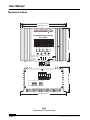
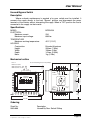
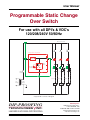
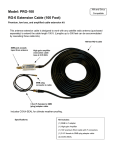
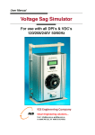
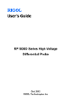
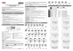
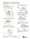
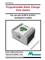
User Manual
Programmable Static Change
Over Switch
For use with all DPI’s & VDC’s
120/208/240V 50/60Hz
Pr
DIP-PROOFING
TECHNOLOGIES
INC.
LEADERS IN VOLTAGE-DIP PROOFING
im
l
e
in
y
r
a
User Manual
Contents
Description - Programmable Static Change Over Switch .. 3
Operation ........................................................................... 3
Sag Simulation .................................................... 3
Soak Test ............................................................. 7
Simulated Sag Profile ...................................................... 10
Specifications................................................................... 11
Block diagram .................................................................. 12
Controls & indicators........................................................ 12
Typical test setup ............................................................. 13
Mechanical Outline .......................................................... 14
Accessories ..................................................................... 15
Page 2
Programmable Static Change Over Switch
User Manual
Description - Programmable Static Change Over Switch (PSCOS)
The PSCOS is intended to be used as a tool to evaluate the effects of momentary
voltage sags and interruptions on industrial controls. When used in conjunction with a Voltage
Dip-Proofing Inverter or a Voltage Dip Compensator and Bypass switch, it may be used to
prove the effectiveness of the DPI or VDC as a solution for these power quality problems. The
PCOSS incorporates a Soak Test function selected via the Function Select menu, that may
be used to perform repetitive testing.
The PSCOC is designed for 120/208/240Vac operation. The main controls and their
functions are listed below, refer to Fig 7 page 12 for their locations :1.
The sag level set by an external variac or transformer ( the sag source ) is indicated
on the LCD display.
2.
A variable interrupt timer that is used to set the duration and Interval of the voltage
sag. Both parameters are set using the programming keys and indicated on the
LCD display. Refer to the menu flow chart and programming key function table in
Fig 3 p6 for Sag Simulation and Fig 4 p9 for Soak Test.
Operation
Sag Simulation
Follow the steps outlined below to set up and operate the PSCOS. Refer to
Fig 3 on page 6 for information on menu layout and programming key functions.
1.
Connect the supply, external Sag Source, Voltage Dip-Proofing Inverter or Voltage
Dip Compensator, Bypass Switch and load to the PSCOS; see Fig 8 page 13.
2.
Set the sag source to zero output and the Bypass Switch to Inverter Bypassed.
3.
Switch on the power to the PSCOS; the display will show:
DIP-PROOFING
TECHNOLOGIES INC.
SAG SIMULATOR AND
SOAK TESTER
SELF TEST PASSED!
FUNCTION SELECT
1 SAG SIMULATOR
2 SOAK TEST
Note: If an error message is displayed and the Simulator shuts down please refer to
Error conditions at the end of this section on page 8.
4.
Press the key to reach the Sag Simulator menu; the display will show:
SAG SIMULATOR
1 START TEST
2 SET PARAMETERS
5.
Press the key to reach the Start Test display; the display will show:
Programmable Static Change Over Switch
Page 3
User Manual
START TEST
VOLTAGE:
DURATION:
000Vac
0.100s
6.
The Sag Depth may be adjusted using the an external variac prior to performing
the test. The value is shown on the Voltage readout. In this case a preset value is
used for the Sag Duration (100ms). The simulator will store the value used for the
last test and use it as the default for the next test.
7.
Press thekey to Start Test or press thekey to return to the Sag Simulator menu.
8.
To set the Sag Parameters to values different to the defaults navigate to the Sag
Simulator menu, press the key to select Set Parameters then press the key
to reach the adjustment menus. The Sag Depth is set using the external variac and
then the interrupt timer should be programmed to set the duration of the voltage sag
to be generated. The two parameters are adjusted as follows :8.1 Set Sag Depth: At the Set Sag Depth Menu press the key to reach the Adjust
Variac menu. Adjust the external variac until desired voltage is indicated on the
display. If a tapped transformer is used as a sag source connect the desired tap.
8.2 Set Sag Duration: From the Set Sag Depth menu press key to select the Set Sag
Duration menu. Press thekey to program the Sag Duration value. Use
theandkeys to select the digit to adjust. The active digit will flash. Use the
keys to increment or decrement the digit to the desired value.
9.
Start Test: When the Sag Voltage and Duration have been set navigate back to
the Sag Simulator menu by pressing the key. Press thekey to reach the Start
Test menu. At this point the variac may be used to readjust the sag voltage. The
voltage setting will be indicated on the display. The supply voltage can be
interrupted by pressing thekey. The effect of the programmed sag can be seen
on the unprotected load; one or more contactors or relays will drop out. The sag
profile can be observed using a power monitor or an oscilloscope if these are
available. The simulation can be tried with various settings (sag depth and
duration) as often as desired to pinpoint sensitive components in the control
system.
10.
Test with DPI or VDC in circuit: The Bypass Switch should now be set to Inverter
in Circuit and the sag simulations repeated to evaluate the effectiveness of using
the Voltage Dip-Proofing Inverter or Voltage Dip Compensator to harden the
controls against momentary sags and interruptions.
Page 4
Programmable Static Change Over Switch
User Manual
11.
Sync pulse output: A synchronization pulse is available at terminals 5 & 6. This
pulse may be used to trigger an oscilloscope in order to display the sag profile. The
output remains at zero volts until a sag is initiated at which time the output rises to
5 volts and remains at this level until the end of the sag duration period. The output
then returns to zero volts. The sync pulse output is electrically isolated.
Programmable Static Change Over Switch
Page 5
Page 6
SYSTEM FAILURE!
PLEASE CONTACT
DIP-PROOFING
TECHNOLOGIES INC.
CURRENT OVERLOAD
OR SHORT CIRCUIT!
SWITCH OFF AND
CHECK THE LOAD.
SUPPLY FREQUENCY NOT
50 or 60Hz!
SWITCH OFF AND ON
TO RETRY.
Power on error messages.
1 SAG SIMULATOR
2 SOAK TEST
FUNCTION SELECT
Displays for 3 sec.
SELF TEST PASSED!
Power on - star t.
SET SAG DURATION
DURATION: 1.000s
SET THE SAG DEPTH BY
ADJUSTING THE VARIAC
SET VOLTAGE: 154Vac
Fig 3
Programming key function table & Sag Simulator menu flowchart.
VOLTAGE: 154Vac
DURATION: 1.000s
SET SAG DURATION
DURATION: 1.000s
SET SAG DEPTH
VOLTAGE: 154Vac
1 START TEST
2 SET PARAMETERS
SAG SIMULATOR
1 START TEST
2 SET PARAMETERS
SAG SIMULATOR
Displays for 3 sec.
DIP-PROOFING
TECHNOLOGIES INC.
SAG SIMULATOR AND
SOAK TESTER.
Key
154Vac
1.000s
Next menu
right
Next menu
left
Next menu
above
Next menu
below
Menu
navigation
Decrement digit
Increment digit
Previous digit
Next digit
Set value
Displays for duration of sag.
VOLTAGE:
DURATION:
>>>
154Vac
1.000s
>>> TESTING
VOLTAGE:
DURATION:
START SAG TEST
User Manual
Programmable Static Change Over Switch
User Manual
Soak Test
Follow the steps outlined below to set up and operate in Soak Tester mode. Refer to
Fig 4 on page 9 for information on menu layout and programming key functions.
1.
Connect the supply, Voltage Dip-Proofing Inverter or Voltage Dip Compensator,
Bypass Switch and load to the PSCOS as shown in Fig 8 page 13.
2.
Set the variac to zero output and the Bypass Switch to Inverter in circuit .
3.
Switch on the power to the PSCOS; the display will show:
DIP-PROOFING
TECHNOLOGIES INC.
SAG SIMULATOR AND
SOAK TESTER
SELF TEST PASSED!
FUNCTION SELECT
1 SAG SIMULATOR
2 SOAK TEST
Note: If an error message is displayed and the Simulator shuts down please refer to
Error conditions at the end of this section on page 8.
4.
Press the key to select Soak Test then Press the key to reach the Soak Test
menu; the display will show:
SOAK TEST
1 START TEST
2 SET PARAMETERS
5.
Press the key to reach the Start Test display; the display will show:
START SOAK TEST
SET VOLTAGE: 000Vac
INTERVAL:
0010s
DURATION:
00.1s
6.
The Sag Depth may be adjusted using the external variac prior to performing the
test. The value is shown on the Voltage readout. Stored values are used for :
6.1 Interval - Interval between consecutive dips - initial default = 10 seconds
6.2 Sag Duration - Duration of the test sag - initial default = 100ms
6.3 Note that the values shown above are factory settings for “first use”. When
parameters are set up for a test the new values are stored and will become the
default values for the next test.
7.
Press thekey to Start Test or press thekey to return to the Soak Test menu.
8.
To set the Soak Test Parameters to values different to the defaults navigate to the
Soak Test menu, press the key to select Set Parameters then press the key
to reach the adjustment menus. Three parameters may be adjusted as follows :-
Programmable Static Change Over Switch
Page 7
User Manual
8.1 Set Dip Interval: At the Set Dip Interval menu press the key to program the Dip
Interval value. Use theand keys to select the digit to adjust. The active digit
will flash. Use the keys to increment or decrement the digit to the desired value.
8.2 Set Dip Duration : At the Set Dip Interval menu press thekey to select the Set
Dip Duration menu. Press thekey to program the Start Dip length value. Use
theand keys to select the digit to adjust. The active digit will flash. Use the
keys to increment or decrement the digit to the desired value.
8.3 Set Sag Depth: The Set Sag Depth is set from the Start Soak Test Menu. Set
Voltage will flash and the current sag level voltage will be displayed. Adjust the
external variac to the desired Sag Depth value. The value may be adjusted at any
time during testing.
9.
Start Test: When the parameters have been set navigate back to the Soak Test
menu by pressing the key. Press thekey to reach the Start Soak Test menu.
Set Voltage will flash; use the variac to adjust the Sag Depth voltage (see 8.3
above). Start the Soak Test by pressing thekey. The display will show:
>>>SOAK TESTING >>>
VOLTAGE:
000Vac
NEXT DIP IN: 0000s
TOTAL DIPS: 0000
10.
Stop or interrupt the test by pressing thekey. The display will show:
SOAK TEST STOPPED!
CONTINUE TEST?
SET UP NEW TEST?
Use the keys to to select Continue Test or Set Up New Test then press
thekey to go to the selected option.
Start up error conditions
1.
Error conditions: The simulator will perform a power on test to check the supply
frequency and the load current. If the supply frequency is not 50 or 60Hz or if there
is an overload then one of the error messages below will be displayed:
SUPPLY FREQUENCY NOT
50 or 60Hz!
SWITCH OFF AND ON
TO RETRY.
or
CURRENT OVERLOAD
OR SHORT CIRCUIT!
SWITCH OFF AND
CHECK THE LOAD.
When an error condition is detected the simulator will shut down automatically and
the error message will remain on the display. Check the test setup for the source
of the problem. To reset the simulator switch the power off and then back on again.
Page 8
Programmable Static Change Over Switch
1 SAG SIMULATOR
2 SOAK TEST
FUNCTION SELECT
Displays for 3 sec.
SELF TEST PASSED!
Power on - star t.
Programmable Static Change Over Switch
t DURATION: 00.0s
SET DIP DURATION
t INTERVAL: 0000s
t DURATION: 00.0s
Fig 4
Programming key function table & Soak Tester flowchart.
SET THE DURATION OF
THE TEST DIP
SET INTERVAL BETWEEN
CONSECUTIVE DIPS
INTERVAL: 0000s
t INTERVAL: 0000s
t DURATION: 00.0s
SET DIP INTERVAL
1 START TEST
2 SET PARAMETERS
SOAK TEST
1 START TEST
2 SET PARAMETERS
SOAK TEST
Displays for 3 sec.
DIP-PROOFING
TECHNOLOGIES INC.
SAG SIMULATOR AND
SOAK TESTER.
Key
Next menu
right
Next menu
left
Next menu
above
Next menu
below
Menu
navigation
Decrement digit
Increment digit
Previous digit
Next digit
Set value
CONTINUE TEST?
SET UP NEW TEST?
SOAK TEST STOPPED!
>>>SOAK TESTING >>>
VOLTAGE:
000Vac
NEXT DIP IN: 0000s
TOTAL DIPS: 0000
Displays for duration of soak test.
START SOAK TEST
SET VOLTAGE: 000Vac
0000s
INTERVAL:
00.0s
DURATION:
User Manual
Page 9
User Manual
Simulated Sag Profile
Supply V
Sag Duration 70ms
300
Sag Depth
50%
200
Sag
Voltage
110Vrms
100
0
-100
-200
-300
Sag Simulator output
Supply voltage - 220V 50Hz
V Sync
0
10
20
30
40
50
Sync pulse output
60
70
80
90
100
Time ms
Terminals 5 & 6
5
0
Duration = 70mS = Sag Duration
Amplitude = 5V
-5
0
10
20
30
40
50
60
70
80
90
100
Time ms
Fig 5
Profile of simulated sag output & sync pulse from simulator.
Page 10
Programmable Static Change Over Switch
User Manual
Programmable Static Change Over Switch Specifications
AC INPUT SUPPLY
Supply voltage:
Maximum input voltage:
Full load current:
120/208/240Vac 50/60Hz
+10%
25A
SAG SOURCE CONTROL
Dependent on external variac or tapped transformer characteristics.
SAG DURATION TIMER - Sag Test
Range:
Setting:
SAG DURATION TIMER - Soak Test
Range:
Setting:
SAG INTERVAL TIMER - Soak Test
Range:
Setting:
0.001 to 9.999 seconds
0.001 second steps
0.1 to 99.9 seconds
0.1 second steps
0 to 9999 s
1 s steps
CONTROLS & INDICATORS
Programming:
Menu/parameter indication:
Four push switches
4 x 20 LCD display
SYNC PULSE OUTPUT
Amplitude:
Polarity:
Electrically isolated output:
Duration:
5V
Positive
Yes
Equal to sag duration
TEMPERATURE
Maximum ambient working temperature:
45°C (113°F)
HOUSING
Construction:
Height:
Width:
Depth:
Mass:
Programmable Static Change Over Switch
Extruded aluminium
220mm (8.66in )
311mm (12.24in)
162mm (6.38in)
6kg (2.7lb)
Page 11
User Manual
Programmable Static Change Over Switch block diagram
6
Controls
5
4 x 20 Display
Program Switches
Line in
1
Static Switch 1
4
Static Switch 2
Load
Sync pulse
Amplitude = 5V
Duration = Sag duration
Sag source in
2
V
Sag voltage
Common
3
Fig 6
Block diagram
Controls & indicators
DIP-PROOFING
TECHNOLOGIES
INC.
Programmable Static Change
Over Switch
FUNCTION SELECT
1 SAG SIMULATOR
2 SOAK TEST
Sag Source in Common Line
Line out
(Variac or Tx)
(Load) Sync
Line in
out 5V
(Supply)
1 2 3 4 5 6
Fig 7
Controls & indicators
Page 12
Programmable Static Change Over Switch
Common line (Supply & Sag Source)
3
Sag Source in (Variac or tapped Tx)
2
Line In (Supply 120/208/240V)
1
1 2 3 4 5 6
Sag Source in Common Line
Line out
(Variac or Tx)
(Load) Sync
Line in
out 5V
(Supply)
1 SAG SIMULATOR
2 SOAK TEST
FUNCTION SELECT
Programmable Static Change
Over Switch
2
3
1 2 3
1 2 3
1
Common Line
Connection
to Inverter
Line out
(Load)
1
1 2 3
Connection
to Supply
2
Inverter in Circuit
Line in
(Supply)
Common line
(Load)
Line Out
Housed
Bypass
Switch
Fig 8
Typical connection diagram.
Ground
Inverter
Running
Voltage-Dip Proofing Inverter
System
OK
INC.
DIP-PROOFING
TECHNOLOGIES
Common
INC.
Line In
DIP-PROOFING
Line Out
Programmable Static Change Over Switch
Inverter
Bypassed
TECHNOLOGIES
Start
Start
C1
C2
Interlock
Stop
Stop
Interlock
B2
B1
C3
Interlock
Start
Stop
B3
Motor Control Centre or load under test
User Manual
Typical test setup
Page 13
User Manual
Mechanical Outline
311mm (12.24")
298mm (11.73")
DIP-PROOFING
TECHNOLOGIES
INC.
FUNCTION SELECT
1 SAG SIMULATOR
2 SOAK TEST
220mm (8.66")
Programmable Static Change
Over Switch
Sag Source in Common Line
Line out
(Variac or Tx)
(Load) Sync
Line in
out 5V
(Supply)
1 2 3 4 5 6
MODEL
VOLTS
SERIAL #
POWER
DATE MFG
HZ
162mm (6.38")
1 2 3 4 5 6
311mm (12.24")
Fig 9
Dimensions (in mm/inches)
Page 14
Programmable Static Change Over Switch
User Manual
Housed Bypass Switch
Description
Where no-break maintenance is required a by pass switch must be installed. It
connects the supply directly to the load, "Bypass" position, and disconnects the power
terminals of the inverter without interrupting the supply. When in "DPI" position the load is
connected to the supply via the inverter.
Specifications
MODEL
ELECTRICAL
Maximum current:
Maximum input voltage:
TEMPERATURE
Maximum working temperature:
HOUSING
Construction:
Height:
Width:
Depth:
Mass:
BPSW25A
25A
600Vac
45°C (113°F)
Extruded Aluminum
202mm (7.95in)
150mm (5.9in)
141mm (5.55in)
1kg (2.2lbs)
Mechanical outline
Note 1:
Dimension units.
Without brackets - mm.
With brackets - inches.
31
(1.22)
41.0
(1.61)
Note 2: Mounting holes 2 x 6 (0.25)Ø.
Line in
2
Line in
(Supply)
2
3
Line out
(Load)
4
41.0
(1.61)
To
Supply 1
Common Line
out
in
50 (1.97)
4
110 (4.33)
3
Line out
DPI
Bypass
2
4
out
in
Common Line
Ground
Screws
1
3
120 (4.72)
1
50 (1.97)
To DPI
or VDC
140 (5.51)
150 (5.90)
Ordering
Stock No:
5003-006
Programmable Static Change Over Switch
Description
Housed By-Pass Switch 25Amp
Page 15
User Manual
Programmable Static Change
Over Switch
For use with all DPI’s & VDC’s
120/208/240V 50/60Hz
Motor Control Centre
B1
B2
B3
Stop
Stop
Stop
Start
Start
Start
Interlock
Interlock
Interlock
C1
C2
C3
Voltage-Dip Proofing Inverter
1
3
Static
Switch
Bridge
Inverter
Storage
Capacitor
2
Main
Breaker
Bypass Switch
Line
Voltage
Control
Voltage
A typical DPI connection diagram
DIP-PROOFING
TECHNOLOGIES
INC.
LEADERS IN VOLTAGE-DIP PROOFING
Doc Ref. 3703-022
Rev. 1.0 September 14th, 2005 : LPW
Measurlogic Inc.
10235 S Progress Way Unit 1,
Parker, CO 80134, USA
Tel:303-364-4368 Fax:425-799-4780
E-mail: [email protected]
web: www.measurlogic.com