1
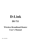
D-Link DI-713 User’s Manual LIMITED WARRANTY D-Link Systems, Inc. (“D-Link”) provides this limited warranty for its product only to the person or entity who originally purchased the product from D-Link or its authorized reseller or distributor. Limited Hardware Warranty: D-Link warrants that the hardware portion of the D-Link products described below (“Hardware”) will be free from material defects in workmanship and materials from the date of original retail purchase of the Hardware, for the period set forth below applicable to the product type (“Warranty Period”) if the Hardware is used and serviced in accordance with applicable documentation; provided that a completed Registration Card is returned to an Authorized D-Link Service Office within ninety (90) days after the date of original retail purchase of the Hardware. If a completed Registration Card is not received by an authorized D-Link Service Office within such ninety (90) day period, then the Warranty Period shall be ninety (90) days from the date of purchase. Product Type Warranty Period Product (excluding power supplies and fans), if purchased and delivered in the fifty (50) United States, or the District of Columbia (“USA”) As long as the original purchaser still owns the product Product purchased or delivered outside the USA One (1) Year Power Supplies and Fans One (1) Year Spare parts and spare kits Ninety (90) days D-Link’s sole obligation shall be to repair or replace the defective Hardware at no charge to the original owner. Such repair or replacement will be rendered by D-Link at an Authorized D-Link Service Office. The replacement Hardware need not be new or of an identical make, model or part; D-Link may in its discretion may replace the defective Hardware (or any part thereof) with any reconditioned product that D-Link reasonably determines is substantially equivalent (or superior) in all material respects to the defective Hardware. The Warranty Period shall extend for an additional ninety (90) days after any repaired or replaced Hardware is delivered. If a material defect is incapable of correction, or if D-Link determines in its sole discretion that it is not practical to repair or replace the defective Hardware, the price paid by the original purchaser for the defective Hardware will be refunded by D-Link upon return to D-Link of the defective Hardware. All Hardware (or part thereof) that is replaced by D-Link, or for which the purchase price is refunded, shall become the property of DLink upon replacement or refund. Limited Software Warranty: D-Link warrants that the software portion of the product “( Software”) will REV: 11062000 1 substantially conform to D-Link’s then current functional specifications for the Software, as set forth in the applicable documentation, from the date of original delivery of the Software for a period of ninety (90) days (“Warranty Period”), if the Software is properly installed on approved hardware and operated as contemplated in its documentation. D-Link further warrants that, during the Warranty Period, the magnetic media on which D-Link delivers the Software will be free of physical defects. D-Link’s sole obligation shall be to replace the non-conforming Software (or defective media) with software that substantially conforms to D-Link’s functional specifications for the Software. Except as otherwise agreed by D-Link in writing, the replacement Software is provided only to the original licensee, and is subject to the terms and conditions of the license granted by D-Link for the Software. The Warranty Period shall extend for an additional ninety (90) days after any replacement Software is delivered. If a material non-conformance is incapable of correction, or if D-Link determines in its sole discretion that it is not practical to replace the non-conforming Software, the price paid by the original licensee for the non-conforming Software will be refunded by D-Link; provided that the non-conforming Software (and all copies thereof) is first returned to D-Link. The license granted respecting any Software for which a refund is given automatically terminates. What You Must Do For Warranty Service: Registration Card. The Registration Card provided at the back of this manual must be completed and returned to an Authorized D-Link Service Office for each D-Link product within ninety (90) days after the product is purchased and/or licensed. The addresses/telephone/fax list of the nearest Authorized D-Link Service Office is provided in the back of this manual. FAILURE TO PROPERLY COMPLETE AND TIMELY RETURN THE REGISTRATION CARD MAY AFFECT THE WARRANTY FOR THIS PRODUCT. Submitting A Claim. Any claim under this limited warranty must be submitted in writing before the end of the Warranty Period to an Authorized D-Link Service Office. The claim must include a written description of the Hardware defect or Software nonconformance in sufficient detail to allow D-Link to confirm the same. The original product owner must obtain a Return Material Authorization (RMA) number from the Authorized D-Link Service Office and, if requested, provide written proof of purchase of the product (such as a copy of the dated purchase invoice for the product) before the warranty service is provided. After an RMA number is issued, the defective product must be packaged securely in the original or other suitable shipping package to ensure that it will not be damaged in transit, and the RMA number must be prominently marked on the outside of the package. The packaged product shall be insured and shipped to D-Link, 53 Discovery Drive, Irvine CA 92618, with all shipping costs prepaid. D-Link may reject or return any product that is not packaged and shipped in strict compliance with the foregoing requirements, or for which an RMA number is not visible from the outside of the package. The product owner agrees to pay D-Link’s reasonable handling and return shipping charges for any product that is not packaged and shipped in accordance with the foregoing requirements, or that is determined by D-Link not to be defective or non-conforming. What Is Not Covered: This limited warranty provided by D-Link does not cover: Products that have been subjected to abuse, accident, alteration, modification, tampering, negligence, misuse, faulty installation, lack of reasonable care, repair or service in any way that is not contemplated in the documentation for the product, or if the model or serial number has been altered, tampered with, defaced or removed; Initial installation, installation and removal of the product for repair, and shipping costs; REV: 11062000 2 Operational adjustments covered in the operating manual for the product, and normal maintenance; Damage that occurs in shipment, due to act of God, failures due to power surge, and cosmetic damage; and Any hardware, software, firmware or other products or services provided by anyone other than D-Link. Disclaimer of Other Warranties: EXCEPT FOR THE LIMITED WARRANTY SPECIFIED HEREIN, THE PRODUCT IS PROVIDED “AS-IS” WITHOUT ANY WARRANTY OF ANY KIND INCLUDING, WITHOUT LIMITATION, ANY WARRANTY OF MERCHANTABILITY, FITNESS FOR A PARTICULAR PURPOSE AND NON-INFRINGEMENT. IF ANY IMPLIED WARRANTY CANNOT BE DISCLAIMED IN ANY TERRITORY WHERE A PRODUCT IS SOLD, THE DURATION OF SUCH IMPLIED WARRANTY SHALL BE LIMITED TO NINETY (90) DAYS. EXCEPT AS EXPRESSLY COVERED UNDER THE LIMITED WARRANTY PROVIDED HEREIN, THE ENTIRE RISK AS TO THE QUALITY, SELECTION AND PERFORMANCE OF THE PRODUCT IS WITH THE PURCHASER OF THE PRODUCT. Limitation of Liability: TO THE MAXIMUM EXTENT PERMITTED BY LAW, D-LINK IS NOT LIABLE UNDER ANY CONTRACT, NEGLIGENCE, STRICT LIABILITY OR OTHER LEGAL OR EQUITABLE THEORY FOR ANY LOSS OF USE OF THE PRODUCT, INCONVENIENCE OR DAMAGES OF ANY CHARACTER, WHETHER DIRECT, SPECIAL, INCIDENTAL OR CONSEQUENTIAL (INCLUDING, BUT NOT LIMITED TO, DAMAGES FOR LOSS OF GOODWILL, WORK STOPPAGE, COMPUTER FAILURE OR MALFUNCTION, LOSS OF INFORMATION OR DATA CONTAINED IN, STORED ON, OR INTEGRATED WITH ANY PRODUCT RETURNED TO D-LINK FOR WARRANTY SERVICE) RESULTING FROM THE USE OF THE PRODUCT, RELATING TO WARRANTY SERVICE, OR ARISING OUT OF ANY BREACH OF THIS LIMITED WARRANTY, EVEN IF D-LINK HAS BEEN ADVISED OF THE POSSIBILITY OF SUCH DAMAGES. THE SOLE REMEDY FOR A BREACH OF THE FOREGOING LIMITED WARRANTY IS REPAIR, REPLACEMENT OR REFUND OF THE DEFECTIVE OR NONCONFORMING PRODUCT. GOVERNING LAW : This Limited Warranty shall be governed by the laws of the state of California. Some states do not allow exclusion or limitation of incidental or consequential damages, or limitations on how long an implied warranty lasts, so the foregoing limitations and exclusions may not apply. This limited warranty provides specific legal rights and the product owner may also have other rights which vary from state to state. REV: 11062000 3 Trademarks Copyright 1999 D-Link Corporation. Contents subject to change without prior notice. D-Link is a registered trademark of D-Link Corporation/D-Link Systems, Inc. All other trademarks belong to their respective proprietors. Copyright Statement No part of this publication may be reproduced in any form or by any means or used to make any derivative such as translation, transformation, or adaptation without permission from D-Link Corporation/D-Link Systems Inc., as stipulated by the United States Copyright Act of 1976. CE Mark Warning This is a Class B product. In a domestic environment, this product may cause radio interference, in which case the user may be required to take adequate measures Warnung! Dies ist in Produkt der Klasse B. Im Wohnbereich kann dieses Produkt Funkstoerungen verursachen. In diesem Fall kann vom Benutzer verlangt werden, angemessene Massnahmen zu ergreifen. Advertencia de Marca de la CE Este es un producto de Clase B. En un entorno doméstico, puede causar interferencias de radio, en cuyo case, puede requerirse al usuario para que adopte las medidas adecuadas. Attention! Ceci est un produit de classe B. Dans un environnement domestique, ce produit pourrait causer des interférences radio, auquel cas l`utilisateur devrait prendre les mesures adéquates. Attenzione! Il presente prodotto appartiene alla classe B. Se utilizzato in ambiente domestico il prodotto può causare interferenze radio, nel cui caso è possibile che l`utente debba assumere provvedimenti adeguati. FCC Warning This equipment has been tested and found to comply with the limits for a Class B digital device, pursuant to part 15 of the FCC Rules. These limits are designed to provide reasonable protection against harmful interference in a residential installation. This equipment generates, uses and can radiate radio frequency energy and, if not installed and used in accordance with the instructions, may cause harmful interference to radio communications. However, there is no guarantee that interference will not occur in a particular installation. If this equipment does cause harmful interference to radio or television reception, which can be determined by turning the equipment off and on, the user is encouraged to try to correct the interference by one or more of the following REV: 11062000 4 measures: -Reorient or relocate the receiving antenna. -Increase the separation between the equipment and receiver. -Connect the equipment into an outlet on a circuit different from that to which the receiver is connected. -Consult the dealer or an experienced radio/ TV technician for help. VCCI Warning REV: 11062000 5 Table of Contents Chapter 1 Introduction.................................................................................1 1.1 Functions and Features...................................................................1 1.2 Packing List ....................................................................................2 Chapter 2 Hardware Installation..................................................................3 2.1 Panel Layout ...................................................................................3 2.2 Procedure for Hardware Installation...............................................5 Chapter 3 Network Settings .........................................................................8 3.1 Make Correct Network Settings to the Computer ..........................8 Chapter 4 Configuring the DI-713...............................................................9 4.1 Start-up and Log in .........................................................................9 4.2 Status.............................................................................................10 4.4 Primary Setup ...............................................................................12 4.5 DHCP Server ................................................................................14 4.6 Virtual Server................................................................................15 4.7 Special AP ....................................................................................16 4.8 Access Control..............................................................................17 4.9 Misc Items ....................................................................................18 4.10 Wireless Setting ..........................................................................19 Appendix A TCP/IP Configuration for Windows 95/98 ...........................20 A.1 Install TCP/IP Protocol into Your PC..........................................20 A.2 Set TCP/IP Protocol for Working with the DI-713 .....................21 REV: 11062000 6 Chapter 1 Introduction Congratulations on your purchase of DI-713 Wireless Broadband Router. The DI-713 is specifically designed for Small Office and Home Office needs. It provides a complete solution for Internet surfing, and it is easy to configure and operate for even non-technical users. Instructions for installing and configuring the DI-713 can be found in this manual. Before you install and use the DI-713, please read this manual carefully to fully understand the functions of the DI-713. 1.1 Functions and Features l l l l l l l l l l l l l High speed Wireless LAN connection 11Mbps data rate by incorporating Direct Sequence Spread Spectrum (DSSS). Roaming Provides seamless roaming within the IEEE 802.11b WLAN infrastructure. IEEE 802.11b compatible Allowing inter-operation among multiple vendors. Auto fallback 11M, 5M, 2M, 1M data rate with auto fallback. Broadband modem and IP sharing Connects multiple computers to a broadband (Cable or DSL) modem or an Ethernet router to share the Internet connection. Auto-sensing Ethernet Switch Equipped with a 3-port 10/100 auto-sensing Ethernet switch. VPN supported Supports multiple PPTP sessions and allows setup of a VPN server and VPN clients. Firewall All unwanted packets from outside intruders are blocked to protect your Intranet. DHCP server supported All of the networked computers can retrieve TCP/IP settings automatically from the DI-713. Web- based configuring Configurable through any networked computer’s web browser using Netscape or Internet Explorer. Access Control supported Allows you to assign different access rights for different users. Virtual Server supported Enables you to expose WWW, FTP and other services on your LAN to be accessible to Internet users outside of you LAN. User-Definable Application Sensing Tunnel User can define the attributes to support the special applications requiring REV: 11062000 1 l multiple connections, like Internet gaming, video conferencing, Internet telephony and so on, then the DI-713 can sense the application type and open a multi-port tunnel for it. DMZ Host supported Lets a networked computer to be fully exposed to the Internet; this function is used when the special application sensing tunnel feature is insufficient to allow an application to function correctly. 1.2 Packing List l l l l l One DI-713 wireless broadband router unit One power adapter Two CAT-5 UTP Straight-through Fast Ethernet cable One CD with HTML Quick Installation Guide and PDF User’s Manual One Quick Installation Guide REV: 11062000 2 Chapter 2 Hardware Installation 2.1 Panel Layout 2.1.1. Front Panel The front panel features three 10/100 Mbps Ethernet ports, one Wide Area network (WAN) port and diagnostic LED indicators. The WAN port connects your DSL or cable modem to the router. The LAN ports are used to connect to your computers or other network devices. LEDs monitor the status of each port. Figure 2-1 Front Panel Port: WAN: the port where you will connect your Cable or DSL modem or Ethernet router. Port 1-3: the ports where you will connect networked computers and other devices. REV: 11062000 3 LED: LED Function Color Status M1 System status 1 Orange Blinking M2 System status 2 Green LAN LAN port activity Green W-Link Backbone activity W-Act Wireless activity Link/Act. 1~3 The DI-713 is working for some service Blinking The DI-713 is being configured or upgraded. Don’t turn it off ! On WAN port activity Blinking On 10/100 1~3 REV: 11062000 Data Rate The WAN port is linked The WAN port is sending or receiving data The LAN port is linked Blinking The LAN port is sending or receiving data Green Blinking Sending or receiving data from wireless to wired backbone Green Blinking Sending or receiving data via wireless On Link status The DI-713 is functioning properly On Orange WAN Description Green Green An active station is connected to the corresponding LAN port. Blinking The corresponding LAN port is sending or receiving data On Data is transmitting in 100Mbps on the corresponding LAN port. 4 2.1.2. Rear Panel Figure 2-2 Rear Panel Ports: Port ON/OFF DC IN Description Power switch Power inlet (DC 5V) COM Serial port (connect analog modem or console cable) 2.2 Procedure for Hardware Installation 1. Decide where to place your Wireless Broadband Router: You can place your Wireless Broadband Router on a desk or other secure surface, or you can mount it on a wall. For optimal performance, place your Wireless Broadband Router in the center of your office (or your home) in a location that is away from any potential source of interference, such as a metal wall or microwave oven. This location must be close to power and a network connection. REV: 11062000 5 2. Setup LAN connection: a. Wired LAN connection: connect an Ethernet cable from your computer’s Ethernet port to one of the LAN ports of the DI-713. b. Wireless LAN connection: make sure the antennas are in a vertical position (if not, rotate over 90 degrees). 3. Setup WAN connection: prepare an Ethernet cable for connecting the DI-713 to your cable/xDSL modem or Ethernet backbone. Figure 2-3 illustrates the WAN connection. Figure 2-3 Setup of LAN and WAN connections for the DI-713. REV: 11062000 6 4. Power on: Connect the power cord to a power outlet and turn the power switch to the on position; the DI-713 will automatically enter the self-test phase. When it is in the selftest phase, the indicators M1 and M2 will be lit for about 10 seconds, and then M1 and M2 will flash 3 times to indicate that the self-test operation has finished. Finally, the M1 will continuously flash once per second to indicate that the DI-713 is in normal operation. REV: 11062000 7 Chapter 3 Network Settings To use the DI-713 correctly, you must properly configure the network settings of your computers. 3.1 Make Correct Network Settings to the Computer The default IP address of the DI-713 is 192.168.0.1, and the default subnet mask is 255.255.255.0. These addresses can be changed to meet your need, but the default values are used in this manual. If the TCP/IP environment of your computer has not yet been configured, you can refer to Appendix B to configure it. For example, 1. configure IP as 192.168.0.5, subnet mask as 255.255.255.0 and gateway as 192.168.0.1, or, 2. configure your computers to load TCP/IP setting automatically, that is, via DHCP server built into the DI-713. After installing the TCP/IP communication protocol, you can use the ping command to check if your computer has successfully connected to the DI-713. The following example shows the ping procedure for Windows 95 platforms. First, execute the ping command from a DOS window ping 192.168.0.1 If the following messages appear: Pinging 192.168.0.1 with 32 bytes of data: Reply from 192.168.0.1: bytes=32 time=2ms TTL=64 a communication link between your computer and the DI-713 has been successfully established. Otherwise, if you get the following messages, Pinging 192.168.0.1 with 32 bytes of data: Request timed out. there must be something wrong with the installation. Follow the steps again to make sure the network settings are correct. You should check the following items in sequence. 1. Is the Ethernet cable correctly connected between the DI-713 and your computer? Tip: The LAN LED of the DI-713 and the link LED of network card on your computer must be lit. 2. Is the TCP/IP environment of your computers properly configured? Tip: If the IP address of the DI-713 is 192.168.0.1, the IP address of your computer must be 192.168.0.X and default gateway must be 192.168.0.1. REV: 11062000 8 Chapter 4 Configuring the DI-713 The DI-713 provides a Web based configuration scheme, that is, configuring by Netscape Communicator or Internet Explorer. This approach can be adopted in any MS Windows, Macintosh or UNIX based platforms a Java compliant browser. 4.1 Start-up and Log in Activate your browser. Then, type the DI-713’s IP address in the Location (for Netscape) or Address (for IE) field and press ENTER. For example: http://192.168.0.1. After the connection is established, you will see the web user interface of the DI-713. There are two appearances of web user interface: for general users and for system administrator. To log in as an administrator, enter the system password (the factory setting is ”admin”) in the System Password field and click on the Log in button. If the password is correct, the web appearance will be changed into administrator configure mode. As listed in its main menu, there are several options for system administration. REV: 11062000 9 4.2 Status This option provides observation of the DI-713’s configuration status. If the WAN port is assigned a dynamic IP address, a “Renew” or “Release” button may appear. You can click this button to manually renew or release the IP. This screen also provides the Firmware Version and MAC Address information. Pressing the Refresh button will update the Device Information screen to show the current status. REV: 11062000 10 4.3 Toolbox This option enables you to change the administrator password, view log information, reboot the DI-713, clone the MAC Address, reset to default settings, and perform a firmware upgrade. Note: we strongly recommend you to change the system password for security reasons. If you forgot the system password, please refer to Appendix A to reset a new one. REV: 11062000 11 4.4 Primary Setup This option is crucial to enable the DI-713 to work properly. The setting items and the web appearance will change depending on the WAN type you choose. Choose the correct WAN type before you start. 1. LAN IP Address: the DI-713’s IP address. The default address is 192.168.0.1. You can change it to meet your need. 2. WAN Type: WAN connection type of your ISP. You can click the Change button to choose the correct setting from the following four options: A. Static IP Address: your ISP assigns you an IP address. B. Dynamic IP Address: Obtain an IP address from your ISP automatically. C. PPP over Ethernet: Some ISPs require the use of PPPoE to connect to their services. This requires a Username and Password provided by the ISP. D. Dial-up Network : Connection to the Internet via PSTN/ISDN modem. REV: 11062000 12 4.4.1 Static IP Address Enter the proper WAN IP Address, Subnet Mask, Gateway, Primary and Secondary DNS settings provided by your ISP. Contact your ISP if you do not have this information. 4.4.2 Dynamic IP Address 1. Host Name: optional. Required by some ISPs, for example, @Home. Renew IP Forever: this feature enables the DI-713 to renew its IP address automatically when the lease time is being expired even if the system is idle. 4.4.3 PPP over Ethernet 2. 1. 2. PPPoE Account and Password : the account and password your ISP assigned to you. If you don't want to change the password, keep it empty. PPPoE Service Name: optional. Input the service name if your ISP requires it. Maximum Idle Time: the maximum time the connection is idle before you are disconnected from your ISP and your PPPOE session is terminated. 4.4.4 Dial-up Network 3. 1. 2. 3. 4. 5. Dial-up Telephone, Account and Password: assigned by your ISP. If you don't want to change the password, keep it empty. Primary and Secondary DNS: automatically assigned if they are configured as "0.0.0.0." Maximum Idle Time: the time of no activity to disconnect your dial-up session. Baud Rate: the communication speed between the DI-713 and your MODEM or ISDN TA. Extra Setting: needed to optimize the communication quality between the ISP and your MODEM or ISDN TA REV: 11062000 13 4.5 DHCP Server The settings of a TCP/IP environment include Host IP, Subnet Mask, Gateway, and DNS configurations. It is not a simple task to correctly configure all the computers in your LAN environment. Fortunately, DHCP provides a rather simple approach to handle all these settings. The DI-713 supports the function of a DHCP server, which is set as default. The DHCP server is able to configure of your computers to “automatic receive IP settings” mode, then when your computer is powered on, it will automatically load the proper TCP/IP settings from the DI-713. The settings of DHCP server options include the following items: 1. DHCP Server: Choose “Disable” or “Enable.” 2. Range of IP Address Pool: Whenever there is a request, the DHCP server will automatically allocate an unused IP address from the IP address pool to the requesting computer. You must specify the starting and ending address of the IP address pool. 3. Domain Name: Optional, this information will be passed to the client. REV: 11062000 14 4.6 Virtual Server The DI-713’s NAT firewall filters out unrecognized packets to protect your Intranet, so all hosts behind the DI-713 are invisible to the outside world. If you wish, you can make some of them accessible by enabling the Virtual Server Mapping. A virtual server is defined as a Service Port, and all requests to this port will be redirected to the computer specified by the Server IP. For example, if you have an FTP server (port 21) at 192.168.0.5, a Web server (port 80) at 192.168.0.7, and a VPN server at 192.168.123.10, then you need to specify the following virtual server mapping table: REV: 11062000 Service Port Server IP Enable 21 192.168.0.5 V 80 192.168.0.7 V 1723 192.168.0.10 V 15 4.7 Special AP Some applications require multiple connections, like Internet games, Video conferencing, Internet telephony and so on. Due to the firewall function, these applications cannot work with a pure NAT router. The Special Applications options allow some of these applications to work with a NAT router. If Special Applications is still insufficient to allow an application to function correctly, try DMZ host in the Misc Items options. 1. Trigger: the outbound port number the application issued first. 2. Incoming Ports: when the trigger packet is detected, the inbound packets to the specified port numbers are allowed to pass the firewall. The DI-713 provides some predefined settings in the gray pad on the bottom of the web page. Choose the Popular application and click Copy to copy the predefined setting. Note! At any time, only one PC can use each Special Application tunnel. REV: 11062000 16 4.8 Access Control Access Control allows you to assign different access rights for different users. First, you have to divide users into different groups. Users are identified by their IP addresses. You can assign the members of Group 1, 2 and 3. The others are all members of the Default Group. Second, you have to assign the access rights of each group. Access rights can allow or block users to access specified TCP and UDP ports. For example: If you want IP addresses 50-99 to block access to port 21 and 119, you would insert 50-99 into the Group 1 members box. Change the Ports drop-down box to Block, and type 21,119 into the box to the right of the Block box. Group Members Default - Group 1 Access Right Comments Allow () No access rights (allow nothing) 50-99 Allow (25,53) Can browse(80), receive(110) and send(25) email only Group 2 100-199 Block (21,119) Cannot read net news(119) and FTP(21) only Group 3 1-9,20 Block () Fully access (block nothing) REV: 11062000 17 4.9 Misc Items 1. 2. IP Address of DMZ Host: DMZ (DeMilitarized Zone) Host is a host without the protection of firewall. It allows a computer to be exposed to unrestricted 2-way communication. Note that, this feature should be used only when needed. Remote Administrator Host: In general, only Intranet user can browse the built-in web pages to perform administration tasks. This feature enables you to perform administration tasks from a remote host. If this feature is enabled, only the specified IP address can perform remote administration. If the specified IP address is 0.0.0.0, any host can connect to the DI-713 to perform administration task. When this feature is enabled, the web port will be shifted to 88. REV: 11062000 18 4.10 Wireless Setting Wireless settings allow you to set the wireless configuration items. 1. Network ID (SSID): Network ID is used for identifying the WLAN. Client stations can roam freely over the DI-713 and other Access Points that have the same Network ID. (The factory setting is “default”) 2. Channel: The radio channel number. The permissible channels depend on the Regulatory Domain. (The factory setting is channel 6) 3. Security: Select the data privacy algorithm you want. Enabling the security can protect your data while it is transferred from one station to another. The standardized IEEE 802.11 WEP (based on a 40 bit shared key) is used here. When you enable the security, please input 10 hex-decimal digits (40 bits) in the text box. REV: 11062000 19 Appendix A TCP/IP Configuration for Windows 95/98 This section is an introduction on you how to install the TCP/IP protocol into your personal computer if the TCP/IP protocol hasn’t been installed yet. Under the normal installation procedure for network adapters, the TCP/IP protocol will be installed automatically. We are assuming that you have successfully installed one network card or wireless adapter on your personal computer. If not, please refer to your network card manual. Moreover, the Section A.2 tells you how to set TCP/IP values for working with the DI-713 correctly. A.1 Install TCP/IP Protocol into Your PC 1. 2. 3. 4. Click the Start button and choose Settings, then click Control Panel. Double click the Network icon and select the Configuration tab in the Network window. Click the Add button to add a network component to your PC. Double click the Protocol to add TCP/IP protocol. REV: 11062000 20 5. Select the Microsoft item in the manufactures list. And choose TCP/IP in the Network Protocols. Click the OK button to return to the Network window. 6. The TCP/IP protocol will be listed in the Network window. Click OK to complete the install procedure and restart your PC to enable the TCP/IP protocol. A.2 Set TCP/IP Protocol for Working with the DI-713 1. Click the Start button and choose Settings, then click Control Panel. REV: 11062000 21 2. Double click the Network icon. Select the TCP/IP line that has been associated to your network card in the Configuration tab of the Network window. 3. Click the Properties button to set the TCP/IP protocol for the DI-713. 4. You have two setting methods to choose from: A. Get IP via DHCP server, or REV: 11062000 22 a. REV: 11062000 Select Obtain an IP address automatically in the IP Address tab. 23 b. REV: 11062000 Make sure no settings are set in the Gateway tab. 24 c. REV: 11062000 Choose Disable DNS in the DNS Configuration tab. 25 B. Configure IP manually a. Select Specify an IP address in the IP Address tab. The default IP address of the DI-713 is 192.168.0.1. So please use 192.168.0.xxx (xxx is between 2 and 254) for IP Address field and 255.255.255.0 for Subnet Mask field. REV: 11062000 26 b. REV: 11062000 In the Gateway tab, add the IP address of the DI-713 (default IP is 192.168.0.1) in the New gateway field and click Add button. 27 c. REV: 11062000 In the DNS Configuration tab, add the DNS values which are provided by the ISP into DNS Server Search Order field and click Add button. 28 Offices AUSTRALIA CANADA CHILE CHINA DENMARK EGYPT FRANCE GERMANY INDIA ITALY JAPAN RUSSIA SINGAPORE S. AFRICA SWEDEN TAIWAN U.K. U.S.A. D-LINK AUSTRALASIA Unit 16, 390 Eastern Valley Way, Roseville, NSW 2069, Australia TEL: 61-2-9417-7100 FAX: 61-2-9417-1077 TOLL FREE: 1800-177-100 (Australia), 0800-900900 (New Zealand) URL: www.dlink.com.au E-MAIL: [email protected], [email protected] D-LINK CANADA 2180 Winston Park Drive, Oakville, Ontario L6H 5W1 Canada TEL: 1-905-829-5033 FAX: 1-905-829-5095 BBS: 1-965-279-8732 FREE CALL: 1-800-354-6522 URL: www.dlink.ca E-MAIL: [email protected] D-LINK SOUTH AMERICA Isidora Goyenechea #2934 of.702, Las Condes, Santiago, Chile TEL: 56-2-232-3185 FAX: 56-2-2320923 URL: www.dlink.cl D-LINK CHINA 2F., Sigma Building, 49 Zhichun Road, Haidian District, 100080 Beijing, China TEL: 86-10-88097777 FAX: 86-10-88096789 URL: www.dlink.com.cn D-LINK DENMARK Naverland 2, DK-2600 Glostrup, Copenhagen, Denmark TEL:45-43-969040 FAX:45-43-424347 URL: www.dlink.dk E-MAIL: [email protected] D-LINK MIDDLE EAST 7 Assem Ebn Sabet Street, Heliopolis Cairo, Egypt TEL: 202-2456176 FAX: 202-2456192 URL: www.dlink-me.com E-MAIL: [email protected] D-LINK FRANCE Le Florilege #2, Allee de la Fresnerie 78330 Fontenay Le Fleury France TEL: 33-1-30238688 FAX: 33-1-3023-8689 URL: www.dlink-france.fr E-MAIL: [email protected] D-LINK GERMANY Bachstrae 22, D-65830 Kriftel Germany TEL: 49-(0)6192-97110 FAX: 49-(0)6192-9711-11 URL: www.dlink.de BBS: 49-(0)6192-971199 (Analog) 49-(0)6192-971198 (ISDN) INFO LINE: 00800-7250-0000 (toll free) HELP LINE: 00800-7250-4000 (toll free) REPAIR LINE: 00800-7250-8000 D-LINK INDIA Plot No.5, Kurla-Bandra Complex Road, Off Cst Road, Santacruz (E), Bombay - 400 098 India TEL: 91-22-652-6696 FAX: 91-22-652-8914 URL: www.dlink-india.com E-MAIL: [email protected] D-LINK ITALIA Via Nino Bonnet No. 6/b, 20154 Milano, Italy TEL: 39-02-2900-0676 FAX: 39-02-2900-1723 URL: www.dlink.it E-MAIL: [email protected] D-LINK JAPAN 10F, 8-8 -15 Nishi-Gotanda, Shinagawa-ku, Tokyo 141 Japan TEL: 81-3-5434-9678 FAX: 81-3-5434-9868 URL: www.d-link.co.jp D-LINK RUSSIA Michurinski Prospekt 49, 117607 Moscow, Russia TEL: 7-095-737-3389, 7-095-737-3492 FAX: 7-095-737-3390 D-LINK INTERNATIONAL 1 International Business Park, #03-12 The Synergy, Singapore 609917 TEL: 65-774-6233 FAX: 65-774-6322 URL: www.dlink-intl.com E-MAIL: [email protected] D-LINK SOUTH AFRICA Unit 2, Parkside 86 Oak Avenue Highveld Technopark Centurion, Gauteng, Republic of South Africa TEL: 27(0)126652165 FAX: 27(0)126652186 D-LINK SWEDEN P.O. Box 15036, S-167 15 Bromma Sweden TEL: 46-(0)8564-61900 FAX: 46-(0)8564-61901 E-MAIL: [email protected] URL: www.dlink.se D-LINK TAIWAN 2F, No. 119 Pao-Chung Road, Hsin-Tien, Taipei, Taiwan, R.O.C. TEL: 886-2-2910-2626 FAX: 886-2-2910-1515 URL: www.dlinktw.com.tw D-LINK EUROPE 4 th Floor, Merit House, Edgware Road, Colindale, London, NW9 5AB, U.K. TEL: 44-20-8731-5555 FAX: 44-20-8731-5511 URL: www.dlink.co.uk E-MAIL: [email protected] D-LINK U.S.A. 53 Discovery Drive, Irvine, CA 92618 USA TEL: 1-949-788-0805 FAX: 1-949-753-7033 INFO LINE: 1-800-326-1688 BBS: 1-949-455-1779, 1-949-455-9616 URL: www.dlink.com E-MAIL: [email protected], [email protected] Tech Support Hours: 6 A.M. to 6 P.M. Pacific Standard Time. Monday through Friday REV: 11062000 29 Registration Card Print, type or use block letters. Your name: Mr./Ms _____________________________________________________________________________ Organization: ________________________________________________ Dept. ____________________________ Your title at organization: _____________________ ___________________________________________________ Telephone: _______________________________________ Fax:________________________________________ Organization's full address: ______________________________________________________________________ _______ _____________________________________________________________________________________ Country: _____________________________________________________________________________________ Date of purchase (Month/Day/Year): ________________________________________ _______________________ Product Model Product Serial No. * Product installed in type of computer (e.g., Compaq 486) * Product installed in computer serial No. (* Applies to adapters only) Product was purchased from: Reseller's name: ______________________________________________________________________________ Telephone: _______________________________________ Fax:________________________________________ Reseller's full address: _________________________________________________________________________ _________________________________________________________________________ _________________________________________________________________________ Answers to the following questions help us to support your product: 1. Where and how will the product primarily be used? oHome oOffice oTravel oCompany Business oHome Business o Personal Use 2. How many employees work at installation site? o1 employee o2-9 o10-49 o50-99 o 100-499 o 500-999 o1000 or more 3. What network protocol(s) does your organization use ? oXNS/IPX oTCP/IP oDECnet oOthers_____________________________ 4. What network operating system(s) does your organization use ? oD-Link LANsmart oNovell NetWare oNetWare Lite oSCO Unix/Xenix oPC NFS o3Com 3+Open oBanyan Vines oDECnet Pathwork oWindows NT oWindows NTAS o Windows '95 oOthers__________________________________________ 5. What network management program does your organization use ? oD-View oHP OpenView/Windows oHP OpenView/Unix o SunNet Manager oNovell NMS oNetView 6000 o Others________________________________________ 6. What network medium/media does your organization use ? oFiber-optics oThick coax Ethernet oThin coax Ethernet o10BASE-T UTP/STP o100BASE-TX o 100BASE-T4 o 100VGAnyLAN oOthers_________________ 7. What applications are used on your network? oDesktop publishing oSpreadsheet oWord processing oCAD/CAM oDatabase management oAccounting oOthers_____________________ 8. What category best describes your company? oAerospace oEngineering oEducation oFinance oHospital oLegal oInsurance/Real Estate oManufacturing oRetail/Chainstore/Wholesale o Government oTransportation/Utilities/Communication oVAR oSystem house/company oOther________________________________ 9. Would you recommend your D-Link product to a friend? oYes oNo oDon't know yet 10.Your comments on the DI-713? __________________________________________________________________________________________ __________________________________________________________________________________________ REV: 11062000 30