1
PMA Prozeß- und Maschinen-Automation GmbH
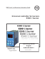
Universal controller for burners
KS40-1 burner
KS40-1 burner
KS40-1 burner
Operating manual
English
expert line
9499-040-66011
Valid from:8473
© PMA Prozeß- und Maschinen-Automation GmbH · Printed in Germany (0207)
All rights reserved. No part of this document may bereproduced or published in any form or by any means
without prior written permission from the copyright owner.
A publication of PMA Prozeß- und Maschinen Automation
P.O.Box 310229
D-34058 Kassel
Germany
Contents
1
2
3
3.1
3.2
3.3
3.4
3.5
4
4.1
4.2
Mounting . . . . . . . . . . . . . . . . . . . . . . . . . . . . . . 5
Electrical connections . . . . . . . . . . . . . . . . . . . . . . . 6
Operation. . . . . . . . . . . . . . . . . . . . . . . . . . . . . . 7
Front view. . . . . . . . . . . . . . . . . . . . . . . . . . . . . . 7
Operating level . . . . . . . . . . . . . . . . . . . . . . . . . . . 8
Self-tuning . . . . . . . . . . . . . . . . . . . . . . . . . . . . . 10
Manual tuning . . . . . . . . . . . . . . . . . . . . . . . . . . . 11
Operating structure . . . . . . . . . . . . . . . . . . . . . . . . 13
Configuration level . . . . . . . . . . . . . . . . . . . . . . . . 14
Configuration with qUIC . . . . . . . . . . . . . . . . . . . . . 14
Configuration without qUIC ( qUIC= OFF) . . . . . . . . . . 18
4.3
5
5.1
6
7
8
9
9.1
Configuration survey: . . . . . . . . . . . . . . . . . . . . 18
Parameter setting level . . . . . . . . . . . .
Input scaling (only visible with qUIC = OFF)
Calibration level . . . . . . . . . . . . . . .
Programmer . . . . . . . . . . . . . . . . .
Technical data . . . . . . . . . . . . . . . .
Safety hints . . . . . . . . . . . . . . . . . .
Resetting to factory setting . . . . . . . . . .
3
.
.
.
.
.
.
.
.
.
.
.
.
.
.
.
.
.
.
.
.
.
.
.
.
.
.
.
.
.
.
.
.
.
.
.
.
.
.
.
.
.
.
.
.
.
.
.
.
.
.
.
.
.
.
.
.
.
.
.
.
.
.
.
.
.
.
.
.
.
.
24
26
27
30
32
36
38
KS40-1 burner
KS40-1 burner
4
Mounting
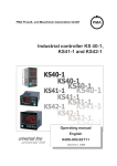
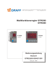
1 Mounting
96 (3.78")
SP.X
126
125
45
SG
Ada
+0,8
1.
.1
8
..0 0
.4
")
11
")
65
.
(4
.0
4
(0
(0
10
max.
60°C
min.
0°C
max.
95% rel.
%
92
)
"
.4
(3.62" +0.03)
min.48 (1.89")
+0,6
(1.77" +0.02)
Err
F
KS 40-1 burner
48 (1.89")
Loc
10V i mA/Pt
mA/Pt
Loc Loc
10V 10V
mA/Pt
Loc 10V mA/Pt
Safety switch
Ü
or:
Ü
*
*
Safety switch:
For access to the safety switches, the controller must be withdrawn from the housing. Squeeze the top and bottom of the front bezel between thumb and forefinger
and pull the controller firmly from the housing.
10V i mA/Pt
Loc
mA/Pt
10V
open
closed
1
Factory setting
1
1
Thermocouple / Pt100 or transducer at InP.1
Pressure transmitter (0..10V) at InP.1
Access to the levels is as adjusted by means of
BlueControl (engineering tool) 2
all levels accessible wihout restriction
2
Default setting: display of all levels
suppressed, password PASS = OFF
switch 10V i mA/Pt always in position left or right. Leaving the
a Safety
safety switch open may lead to faulty functions!
l
Caution! The unit contains ESD-sensitive components.
5
KS40-1 burner
Electrical connections
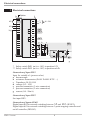
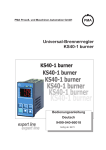
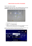
2 Electrical connections
P
Option
A
1
di2
(2)
1
3
2
4
di3
L
N
90...250V
3
5
6
Ut(+)
4
5
6
OUT1
OUT2
7
8
OUT3
g h
9
10
c
g b
+
INP2
100%
11
12
0%
13
0%
14
15
+
a
+
10V *
-
1
2
3
2
100%
+
20mA **
-
1
INP1
b
c
d
e
f
g
* Safety switch INP1 (mA i 10V) in position 10V
** Safety switch INP1 (mA i 10V) in position mA/Pt
Connection of input INP1
Input for variable x1 (process value)
a thermocouple
b resistance thermometer (Pt100/ Pt1000/ KTY/ ...)
c Transducer 50-30-50 W
d voltage (0/2...10V)
e pressure transmitter (3-wire connection)
f pressure transmitter (2-wire connection)
g current (0/4...20mA)
Connection of input INP2
See input INP1.
Connection of inputs di2/di3
Digital input di2 for external switching between SP and SP.2 (SP/SP2).
Digital input di3 for external switching between 3-point-stepping controller and
on/off controller (DPS/SG).
KS40-1 burner
6
Operation
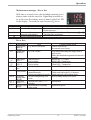
3 Operation
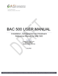
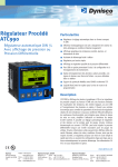
3.1 Front view
1
1
0
!
"
§
$
SP.x
125
%
OK
SG
Ada
Err
2
3
&
4
5
6
7
8
9
KS 40-1 burner
Front view
3
126.
è
g
2
1 Status of switching outputs
OuT.1... 3
2 Lit with limit value 1 not
exceeded
3 Process value display
4 Controller works as on/off
controller
5 Self-tuning active
6 Entry in error list
7 Set-point, controller output
8 Enter key:
calls up extended operating
level / error list
9 Up/down keys:
changing the set-point or the
controller output value
0 Set-point SP.2 or SP.E is
effective
! Set-point gradient effective
" Manual mode
§ Function key
$ Manual-automatic-mode
switching ( " )
% PC connection for BlueControl
(engineering tool)
& Signalization
PArA level (burns)
ConF level (blinks)
In the upper display line, the process value is always displayed. At parameter,
configuration, calibration as well as extended operating level, the bottom display
line changes cyclically between parameter name and parameter value.
7
KS40-1 burner
Operation
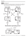
3.2 Operating level
The content of the extended operating level is determined by means of BlueControl (engineering tool). Parameters which are used frequently or the display of
which is important can be copied to the extended operating level.
Automatic
126
125
È
Ì
time
out
Manual
126
iÒ i
Ù
y 21
È
Ì
Ù
Ò
126
126
y 21
Ù
time
out
125
È
Ì
only
display
Ù
Extended operating level
time
out
Errorliste (if error exists)
126
FbF.1
KS40-1 burner
display
126
2
switching
Err
8
Err
Operating level
Operation
Maintenance manager / Error list
With one or several errors, the extended operating level
always starts with the error list. Signalling an actual entry in the error list (alarm, error) is done by the Err LED
in the display. To reach the error list press Ù twice.
Err LED status
Signification
blinks
Alarm due to existing error
lit
Error removed,
Alarm not acknowledged
No error,all alarm entries deleted
off
-
SP.X
126
125
SG
Ada
Err
Proceed as follows
Determine the error type in the error list via the error number
Remove the error
Acknowledge the alarm in the error list pressing key È or Ì
The alarm entry was deleted.
Error list:
Name
E.1
E.2
Description
Cause
Internal error, - E.g. defective EEPROM
cannot be
removed
Internal error, - e.g. EMC trouble
can be reset
FbF.1
/2
Sht.1
/2
POL.1
Sensor break
INP1 / 2
Short circuit
INP1 / 2
INP1 polarity
error
LooP Control loop
alarm (LOOP)
-
Sensor defective
Faulty cabling
Sensor defective
Faulty cabling
Faulty cabling
- Input signal defective or not
connected correctly
- Output not connected correctly
AdA.H Self-tuning
- See Self-tuning heating error
heating alarm
status
(ADAH)
LiM.1/ stored limit
- adjusted limit value 1 / 2 / 3
2 / 3 alarm 1 / 2 / 3
exceeded
Inf.1 time limit value - adjusted number of operating
message
hours reached
Operating level
Possible remedial action
- Contact PMA service
- Return unit to our factory
- Keep measurement and power supply cables in
separate runs
- Ensure that interference suppression of contactors is
provided
- Replace INP1 / 2 sensor
- Check INP1 / 2 connection
- Replace INP1/ 2 sensor
- Check INP1 / 2 connection
- Reverse INP1 polarity
-
Check heating or cooling circuit
Check sensor and replace it, if necessary
Check controller and switching device
see Self-tuning heating error status
- check process
- application-specific
9
KS40-1 burner
Operation
Error status (error status 3 - 9 only with error AdA.H / AdA.C ):
Error status
0 No error/message
1 Stored error
2 Existing error
3 Faulty control action
4 No response of process
variable
5 Low reversal point
6
Danger of exceeded
set-point (parameter
determined)
7 Output step change too
small (dy > 5%)
8 Set-point reserve too
small
9 Impulse tuning failed
Signification
not visible, except with acknowledgement
Change to error status 0 after acknowledgement in error list
Change to error status 1 after error removal
Re-configure controller (inverse i direct)
The control loop is perhaps not closed: check sensor, connections and process
Increase ( ADA.H) max. output limiting Y.Hi or decrease
( ADA.C) min. output limiting Y.Lo
If necessary, increase (inverse) or reduce (direct) set-point
Increase ( ADA.H) max. output limiting Y.Hi or reduce
( ADA.C) min. output limiting Y.Lo
Increase set-point (invers), reduce set-point (direct) or increase set-point
range (r PArA / SEtp / SP.LO and SP.Hi )
The control loop is perhaps not closed: check sensor, connections and process
3.3 Self-tuning
After starting by the operator, the controller makes a self-tuning attempt. The
controller uses the process characteristics for quick line-out to the set-point without overshoot.
g
ti and td are taken into account only, if they were not set to
OFFpreviously.
Self-tuning start
The operator can start self-tuning at any time. For this, keys Ù and È must be
pressed simultaneously. The AdA LED starts blinking.
The controller outputs 0% or Y.Lo, waits until the process is at rest and starts
self-tuning (AdA LED lit permanently).
The self-tuning attempt is started when the following prerequisite is met:
w The difference between process value i set-point must be ³ 10% of the
set-point range ( SP.Hi - SP.LO) (with inverse action: process value smaller
than set-point, with direct action: process value higher than set-point).
After successful self-tuning, the AdA-LED is off and the controller continues
operating with the new control parameters.
Self-tuning cancellation by the operator:
Self-tuning can always be cancelled by the operator. For this, press Ù and È
key simultaneously. The controller continues operating with the old parameters in
automatic mode in the first case and in manual mode in the second case.
KS40-1 burner
10
Self-tuning
Operation
Self-tuning cancellation by the controller:
If the Err LED starts blinking while self-tuning is running, successful self-tuning
is prevented due to the control conditions. In this case, self-tuning was cancelled
by the controller. The controller switches off its outputs (controller output 0%).
Acknowledgement procedures in case of unsuccessful self-tuning:
1. Press keys Ù and È simultaneously:
The controller continues controlling using the old parameters in automatic
mode. The Err LED continues blinking, until the self-tuning error was
acknowledged in the error list.
2. Press key Ù :
Display of error list at extended operating level. After acknowledgement of
the error message, the controller continues control in automatic mode
using the old parameters.
Cancellation causes:
r page 9: "Error status self-tuning heating ( ADA.H) and cooling ( ADA.C)"
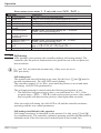
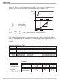
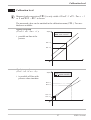
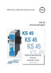
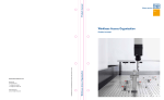
Examples for self-tuning attempt 3-point-stepping controller
After the start (1) the controller
closes the actuator (2 Out.3).
When the difference between
process value and set-point is
big enough (3), the changing of
the process value is monitored
for 1 min. (4). Afterwards the
actuator is opened (5 Out.1).
If the reversal point is reached
(6) or there are made enough
measurements, the parameters
are detected and are adopted.
W
X
t
1 min
t
1 2 3 4
5
6
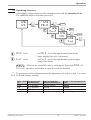
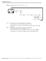
3.4 Manual tuning
The optimization aid should be used with units on which the control parameters
shall be set without self-tuning.
For this, the response of process variable x after a step change of correcting variable y can be used. Frequently, plotting the complete response curve (0 to
100%) is not possible, because the process must be kept within defined limits.
Manual tuning
11
KS40-1 burner
Operation
Values Tg and xmax (step change from 0 to 100 %) or Dt and Dx (partial step response) can be used to determine the maximum rate of increase vmax.
100%
y
Yh
0%
t
x
Tg
Xmax
y =correcting variable
Yh = control range
Tu = delay time (s)
Tg = recovery time (s)
Xmax = maximum process value
Vmax=
{X
{t
t
Tu
Xmax { x
= max. rate of increase of process value
=
{t
Tg
The control parameters can be determined from the values calculated for delay
time Tu , maximum rate of increase vmax, control range Xh and characteristic K according to the formulas given below. Increase Xp, if line-out to the set-point oscillates.
Parameter adjustment effects
Parameter
Pb1 higher
lower
td1 higher
lower
ti1 higher
lower
Control
increased damping
reduced damping
reduced damping
increased damping
increased damping
reduced damping
K = Vmax * Tu
Line-out of disturbances
slower line-out
faster line-out
faster response to disturbances
slower response to disturbances
slower line-out
faster line-out
Formulas
controller behavior
PID
With 2-point and
PD
3-point controllers,
the cycle time must be PI
P
adjusted to
t1 / t2 £ 0,25 * Tu 3-point-stepping
KS40-1 burner
Pb1 [phy. units]
1,7 * K
0,5 * K
2,6 * K
K
1,7 * K
12
Start-up behaviour
slower reduction of duty cycle
faster reduction of duty cycle
faster reduction of duty cycle
slower reduction of duty cycle
slower reduction of duty cycle
faster reduction of duty cycle
td1 [s]
2 * Tu
Tu
OFF
OFF
Tu
ti1 [s]
2 * Tu
OFF
6 * Tu
OFF
2 * Tu
Manual tuning
Operation
3.5 Operating structure
After supply voltage switch-on, the controller starts with the operating levels.
The controller status is as before power off.
126
126
Ù
125
PArA
3 sec.
Ì
Ù
PASS
126
ConF
Ù
126
Ì
CAL
Ì
PASS
Ù
PASS
126
Ù
End
g
PArA - level:
At PArA - level, the right decimal point of the
upper display line is lit continuously.
g
ConF - level:
At ConF - level, the right decimal point of upper
display line blinks
PASS
All levels are accessible only by entering the Password (PASS). If
the safety switch Loc is open all levels are disabled
get access to the configuration and the parameters the saftey switch Loc must
a To
be closed (factory setting).
Safety switch
Loc
closed
open
open
open
Operating structure
Password entered
with BluePort®
OFF / password
OFF / password
OFF
Password
Function disabled or
enabled with BluePort®
disabled / enabled
disabled
enabled
enabled
13
Access via the instrument front
panel:
enabled
disabled
enabled
enabled after password entry
KS40-1 burner
Configuration level
4 Configuration level
4.1 Configuration with qUIC
At configuration level, the controller function is determined by changing configuration word Con1 . Con1 and the code adjusted for Con1 are displayed alternately on the lower display line.
r
126 r Ù r
SP.X
125
SG
Ada
Err
3 sec.
PArA
Ì
ConF
r Ù r qUIC r Ù r
È
Con1 Ì
rÙ
123.8 123.8
Con1
1520
A BC D
Code signification:
0
1
2
0
Reaction at sensor break as process value higher than set-point.
Reaction at sensor break as process value smaller than set-point
Only P30/W connection, always process value smaller than set-point *
B
Potentiometric transducer 50-30-50 [ / pressure sensor 0..10V, display range
0,0...100,0 (%)
1
Potentiometric transducer 50-30-50 [ / pressure sensor 0..10V, display range
0,00...1,00 (bar)
2
Potentiometric transducer 50-30-50 [ / pressure sensor 0..10V, display range
0,0...16,0 (bar)
3
Potentiometric transducer 50-30-50 [ / pressure sensor 0..10V, display range
0,0...40,0 (bar)
4
Resistance thermometer Pt 100 [ , range 0...200°C
5
Resistance thermometer Pt 100 [ , range 0...400°C
6
Thermocouple type L, range 0...900°C
7
Thermocouple type K, range 0...1350°C
C
0
Signaller with switching
1
3-point signaller
2
3-point stepping controller (DPS) switchable to signaller (SG)
3
3-point stepping controller (DPS) switchable to 3-point signaller (SG)
D
0
Not changeable
* Only possible with A = 2 and B = 0 … 3
A
KS40-1 burner
14
Configuration with qUIC
Configuration level
After exit from the configuration level (see page 43, the controller is re-initialized (all display elements are lit) and changes over to normal operation (operating
level).
g
Leading zeros are not displayed (ex.: display 400 with code 0400)
Configuration example 1 (code 0400):
KS40-1 as a signaller with
switch-over contact for 2-stage burner:
Measuring range 0...200°C,
Resistance thermometer Pt 100,
Reaction at sensor break
as process value higher than set-point.
123.8 123.8
Con1
Configuration example 2 (code 2120):
KS40-1 as 3-point stepping controller:
Connection to pressure transmitter P30/W,
Measuring range 0,00...1,00 bar,
Reaction at sensor break as process value
smaller than set-point.
400
123.8 123.8
Con1
2120
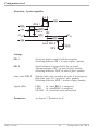
Function: Signaller with switch-over contact
CAUTION: The two relays
1 and 2 are coupled, i.e.
the contacts have
switch-over function. Ensure that the two relays are
not energized or de-energi-X W
zed simultaneously. Exception: de-energized
condition.
W
ON
OUT1
OFF
Sd1 = Sd2
ON
OUT2
OFF
H.1
ON
Limit OUT3
XW
OFF
HYS.1
Settings:
Sd1: in physical values
The relay is de-energized when exceeding the limit.
Upper limit value H.1 : in units of phys. quantity.
Switching difference HYS.1 : in units of phys.quantity
LED1:
lit when OUT1 is energized
LED2:
lit when OUT2 is energized
LED3:
lit when OUT3 is energized
OK-LED: lit, unless the limit value is reached
Switching differences:
Limit value OUT3:
Signalling LEDs:
Parameter:
Configuration with qUIC
see chapter 5 “Parameter level”
15
KS40-1 burner
Configuration level
Function: 3-point signaller
Sd1
ON
OFF
ON
OUT1
Sd2
-X W
ON
d.SP
OUT2
OFF
W
XW
H.1
Limit OUT3
OFF
HYS.1
Settings:
OUT1:
Switch-on point is coupled with the set-point.
Switching difference Sd1: in units of phys. quantity.
OUT2:
Switch-off point is always below the set-point!
Adjustment range d.SP : in units of phys. quantity
Switching difference Sd2: in units of phys. quantity.
Limit value OUT3:
With the limit value exceeded, the relay is de-energized.
High limit value H.1: in units of phys. quantity.
Switching difference HYS.1: in units of phys.quantity.
Signal LEDs:
LED1:
lit, when OUT1 is energized
LED2:
lit, when OUT2 is energized
OK LED: lit, when limit value not reached
Parameters:
see chapter 5 “Parameter level”
KS40-1 burner
16
Configuration with qUIC
Configuration level
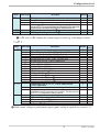
Function: 3-point stepping controller
W
-X W
OFF
OUT1
ON
ON
OUT2
XW
XSd
-A
A
SH
ON
H.1
Limit OUT3
OFF
HYS.1
Settings:
Controller:
SH: in units of phys. quantity
Response threshold A: 0,5 w SH
Switching difference XSd : 0,06 w SH + 0,08
Actuator travel time tt: 3...9999 s
Min.duty cycle: fixed, TEmin = 100 ms
Control parameters:
Pb1 = 0,01...9999 : in unit of phys. quantity °C or °F
(number of digits behind the decimal point is determined
by CON1)
Ti = 1...9999 s ( OFF = no I-action)
td = 1...9999 s ( OFF = no D-action)
Limit value OUT3:
With exceeded limit value, the relay is de-energized.
High limit value H.1 : in units of phys. quantity
Switching difference HYS.1 : in units of phys. quantity
Signalling LEDs:
LED1:
lit when OUT1 is energized
LED2:
lit when OUT2 is energized
OK LED: lit, unless limit value is reached
De-energized condition: all relays de-energized, contacts open
Parameters:
Configuration with qUIC
see chapter 5 “Parameter level”
17
KS40-1 burner
Configuration level
4.2 Configuration without qUIC ( qUIC= OFF)
When key Ù is kept pressed during controller supply voltage switch-on, the
configuration is switched off with qUIC.
Now, all configuration settings are available to the user.
For changing back to configuration with qUIC , the two keys Ì È must be
kept pressed during controller supply voltage switch-on.
a Hereby, the controller is reset to the factory-set default values !
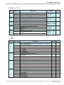
4.3 Configuration survey:
Con1
Name
Value range
Description
Con1 0000...2330 qUIC - Configuration
Default
Own
setting
0000
Wire hook switches (on electronic card)
Name
Value range
Description
Default
Own
setting
Loc open or closed Wire hook switch for locking the ConF- and PArA- level (if closed
enabled with BlueControl)
InP.1 mA/Pt or 10V Wire hook switch for chosing InP.1 signal type
mA/Pt
Cntr
Name
Value range
SP.Fn
0
C.Fnc
1
8
0
1
2
3
4
7
8
9
mAn
0
1
C.Act
0
1
KS40-1 burner
Description
Default
Basic configuration of setpoint processing
set-point controller can be switched over to external set-point (->
LOGI/ SP.E)
programmer
standard controller with external offset (SP.E)
Control behavior (algorithm)
2-point signaller
PID controller (2-point and continuous)
D/ Y/Off, or 2-point controller with partial/full load switch-over
2 x PID (3-point and continuous)
3-point stepping controller
3-point signaller
3-point stepping controller switchable to signaller
3-point stepping controller switchable to 3-point signaller
Manual operating permitted
no
yes (see also LOGI/ mAn)
Method of controller operation
Inverse, e.g. heating
Direct, e.g. cooling
0
18
Own
setting
0
1
0
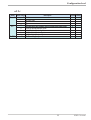
Configuration without qUIC ( qUIC= OFF)
Configuration level
Name
Value range
Description
Default
FAIL
Behavior at sensor break
Controller outputs switched of
y = Y2
y=meanoutput.Themaximumpermissibleoutputcanbeadjustedwith
parameterYm.H.Topreventdeterminationofinadmissiblevalues,meanvalue
formationisonlyifthecontroldeviationislowerthanparameterL.Ym.
rnG.L -1999...9999 X0 (low limit range of control) 1
rnG.H -1999...9999 X100 (high limit range of control) 1
Own
setting
1
0
1
2
0
100
1 rnG.L and rnG.H indicate the control range to which e.g. self-tuning is related.
InP.1
Name
Value range
S.tYP
Description
Default
0
1
2
Sensor type selection
Thermocouple type L (-100...900°C) , Fe-CuNi DIN
Thermocouple type J (-100...1200°C) , Fe-CuNi
Thermocouple type K (-100...1350°C), NiCr-Ni
3
4
5
Thermocouple type N (-100...1300°C), Nicrosil-Nisil
Thermocouple type S (0...1760°C), PtRh-Pt10%
Thermocouple type R (0...1760°C), PtRh-Pt13%
20
21
22
23
30
40
50
51
52
Pt100 (-200,0 ... 100,0 °C)
Pt100 (-200,0 ... 850,0 °C)
Pt1000 (-200,0...200,0 °C)
KTY 11-6 (special 0...4500 Ohm)
0...20mA / 4...20mA 2
0...10V / 2...10V 2
Potentiometer 0...160 Ohm 2
Potentiometer 0...450 Ohm 2
Potentiometer 0...1600 Ohm 2
Linearization (only at S.tYP = 30 (0..20mA) and 40
(0..10V) adjustable)
None
Linearization to specification. Creation of linearization table
with BlueControl (engineering tool) possible. The characteristic
for KTY 11-6 temperature sensors is preset.
Measured value correction ( scaling
Without scaling
Offset correction (at CALlevel)
2- point correction (at CALlevel)
Scaling (at PArA level)
S.Lin
0
1
Corr
0
1
2
3
Own
setting
50
0
2
2 With current, voltage or potentiometer input signals, scaling is required (see section 5.1).
19
KS40-1 burner
Configuration level
InP.2
Name
Value range
I.Fnc
0
2
S.tYP
20
21
22
30
50
51
52
Corr
0
1
2
3
Description
Default
Function selection of INP2
No function
External set-point SP.E (switching -> LOGI/ SP.E)
Sensor type selection
Pt100 (-200,0 ... 100,0 °C)
Pt100 (-200,0 ... 850,0 °C)
Pt1000 (-200,0...200,0 °C)
0...20mA / 4...20mA 1
Potentiometer ( 0...160 Ohm) 1
Potentiometer ( 0...450 Ohm) 1
Potentiometer ( 0...1600 Ohm) 1
Measured value correction / scaling
Without scaling
Offset correction (at CALlevel)
2-point correction (at CALlevel)
Scaling (at PArA level)
Own
setting
0
30
0
1 With current or potentiometer input signals, scaling is required (see section 5.1).
Lim
Name
Value range
Fnc.1
Fnc.2
Fnc.3
Src.1
Src.2
Src.3
0
1
2
0
1
2
6
7
LP.AL
0
1
KS40-1 burner
Description
Default
Function of limit 1 / 2 / 3
Switched off
Measured value monitoring
Measured value monitoring + alarm status storage. A stored
limit value can be reset via error list, Ò-key or a digital input (
-> LOGI/ Err.r)
Source of limit 1 / 2 / 3
Process value = absolut alarm
Control deviation Xw (process value - set-point) relativ alarm
Control deviation Xw (relativ alarm) with suppression after
start-up and set-point change
Effective set-point Weff
Correcting variable (controller output)
Monitoríng of control loop interruption
Switched off
LOOP alarm active
20
1/0/0
1/0/0
0
Own
setting
Configuration level
Out.1 / 2 / 3
Name
Value range
O.Act
0
1
Y.1
Y.2
0
1
Lim.1
Lim.2
Lim.3
LP.AL
0
1
0
1
FAi.1
FAi.2
0
1
Description
Own
setting
Default
Out.1: 0
Out.2: 0
Out.3: 1
Method of operation of output OUT1
Direct / normally open
Inverse / normaly closed
Controller output Y1 / Y2
Not active
Active
Limit 1 / 2 / 3 signal
Not active
Active
Interruption alarm signal (LOOP)
Not active
Active
INP1 / INP2 error signal
Not active
Active
Out.1: 0 / 0 / 0
Out.2: 0 / 0 / 0
Out.3: 1 / 0 / 0
Description
Default
Out.1: 1 / 0
Out.2: 0 / 1
Out.3: 0 / 0
Out.1: 0
Out.2: 0
Out.3: 0
Out.1: 0 / 0
Out.2: 0 / 0
Out.3: 1 / 0
LOGI
Name
Value range
L_r
0
1
3
4
SP.2
5
0
3
4
SP.E
5
0
1
3
4
Y2
5
0
3
4
5
6
Local / Remote switching (Remote: adjusting of all values by
front keys is blocked)
No function
Always active
DI2 switches *
DI3 switches *
è key switches *
Switching to second set-point SP.2
No function
DI2 switches *
DI3 switches *
è key switches *
Switching to external set-point SP.E
No function
Always active
DI2 switches *
DI3 switches *
è key switches *
Y/Y2 switching
No function
DI2 switches *
DI3 switches *
è key switches *
Ò key switches *
21
Own
setting
0
3
0
0
KS40-1 burner
Configuration level
Name
Value range
mAn
0
1
3
4
5
6
C.oFF
0
3
4
5
6
m.Loc
0
3
4
Err.r
5
0
3
4
5
6
SG
0
3
4
P.run
5
0
3
4
di.Fn
5
0
1
2
Description
Default
Automatic/manual switching
No function
Always active
DI2 switches *
DI3 switches *
è key switches *
Ò key switches *
Switch of the controller
No function
DI2 switches *
DI3 switches *
è key switches *
Ò key switches *
Blocage of the Ò key
No function
DI2 switches *
DI3 switches *
è key switches *
Reset of all error list entries
No function
DI2 switches *
DI3 switches *
è key switches *
Ò key switches *
Switching of the controller behavior between 3-point-stepping
controller and signaller
No function
DI2 switches *
DI3 switches *
è key switches *
Programmer Run/Stop
No function
DI2 switches *
DI3 switches *
è key switches *
Function of digital inputs (valid for all inputs)
Direct
Inverse
Toggle key function
6
0
0
0
4
5
0
* Multiple switching is possible and should be excluded on demand.
KS40-1 burner
22
Own
setting
Configuration level
othr
Name
Value range
Unit
0
1
2
dP
C.dEl
0
1
2
3
0...200
Description
Default
Unit
Without unit
°C
°F
Decimal point (max. number of digits behind the decimal point)
No digit behind decimal point
1 digit behind decimal point
2 digits behind decimal point
3 digits behind decimal point
Modem delay [ms]
23
Own
setting
1
0
0
KS40-1 burner
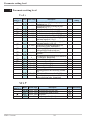
Parameter setting level
5 Parameter setting level
Cntr
Visible
Name Value range
with qUIC
f
f
Pb1
1...9999
Pb2
1...9999
ti1 1...9999
ti2 1...9999
td1 1...9999
td2 1...9999
t1 0,4...9999
f
f
t2
0,4...9999
SH
0...9999
f
Sd1 0,0...9999
f
Sd2 0,0...9999
f
d.SP -1999...999
f
f
tP
tt
Y.Lo
Y.Hi
Y2
Y.0
9
0,1...9999
3...9999
-120...120
-120...120
-120...120
-120...120
Ym.H -120...120
L.Ym 0...9999
Description
Default
Own
setting
10
Proportional band 1 (heating) in phys.
dimensions (e.g. °C)
10
Proportional band 2 (cooling) in phys.
dimensions (e.g. °C)
10
Integral action time 1 (heating) [s]
10
Integral action time 2 (cooling) [s]
10
Derivative action time 1 (heating) [s]
10
Derivative action time 2 (cooling) [s]
Minimal cycle duration 1 (heating) [s]. The 10
minimum impulse is 1/4 x t1
Minimal cycle duration 2 (heating) [s]. The 10
minimum impulse is 1/4 x t2
1
Dead zone or switching differential for
on-off control [phys. dimensions)
0,1
Switching differntial relais 1 for signaller
with partial/full load switch-over
0,1
Switching differntial relais 2 for 3-point
signaller
Trigger point speration for series contact D 0
/ Y / Off [phys. dimensions]
OFF
Minimum impulse [s]
60
Actuator response time for servo-motor [s]
0
Lower output limit [%]
100
Upper output limit [%]
0
2. correcting variable
0
Working point for the correcting variable
[%]
5
Limitation of the mean value Ym [%]
8
Max. deviation xw at the start of mean
value calculation [phys. dimensions]
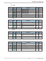
SETP
Visible
with qUIC
f
KS40-1 burner
Name
Value range
Description
SP.LO -1999...9999 Set-point limit low for Weff
SP.Hi -1999...9999 Set-point limit high for Weff
SP.2 -1999...9999 Set-point 2.
r.SP
0...9999 Set-point gradient [/min]
24
Default Own setting
0
100
20
OFF
Parameter setting level
ProG
Visible
with qUIC
Name
Value range
SP.01
Pt.01
SP.02
Pt.02
SP.03
Pt.03
SP.04
Pt.04
-1999...9999
0...9999
-1999...9999
0...9999
-1999...9999
0...9999
-1999...9999
0...9999
Description
Segment end set-point 1
Segment time 1 [min]
Segment end set-point 2
Segment time 2 [min]
Segment end set-point 3
Segment time 3 [min]
Segment end set-point 4
Segment time 4 [min]
Default Own setting
100
10
100
10
200
10
200
10
InP.1
Visible
with qUIC
Name
Value range
Description
Default
InL.1 -1999...9999 Input value for the lower scaling point
OuL.1 -1999...9999 Displayed value for the lower scaling
38,5
0
InH.1 -1999...9999 Input value for the upper scaling point
OuH.1 -1999...9999 Displayed value for the lower scaling
61,5
100
Own
setting
point
t.F1
point
-1999...9999 Filter time constant [s]
0,5
InP.2
Visible
with qUIC
Name
Value range
Description
InL.2 -1999...9999 Input value for the lower scaling point
OuL.2 -1999...9999 Displayed value for the lower scaling
point
InH.2 -1999...9999 Input value for the upper scaling point
OuH.2 -1999...9999 Displayed value for the upper scaling
point
Default
Own
setting
0
0
100
100
Lim
Visible
with qUIC
f
f
Name
Value range
L.1
H.1
HYS.1
L.2/3
H.2/3
HYS.2/
3
-1999...9999
-1999...9999
0...9999
-1999...9999
-1999...9999
0...9999
Description
Default
Own
setting
OFF
20
0,1
OFF
OFF
0,1
Lower limit 1
Upper limit 1
Hysteresis limit 1
Lower limit 2 / 3
Upper limit 2 / 3
Hysteresis limit 2 / 3
25
KS40-1 burner
Parameter setting level
5.1 Input scaling (only visible with qUIC = OFF)
When using current or voltage signals as input variables for InP.1 or InP.2,
scaling of input and display values at parameter setting level is required. Specification of the input value for lower and higher scaling point is in the relevant electrical unit (mA/ V).
phys.
quantity
OuH.x
phys. quantity
mA / V
OuL.x
InH.x mA/V
InL.x
5.1.1 Input Inp.1
g
Parameters InL.1 , OuL.1, InH.1 and OuH.1 are only visible if
ConF / InP.1 / Corr = 3 is chosen.
S.tYP
30
(0...20mA)
40
(0...10V)
Input signal
0 … 20 mA
4 … 20 mA
0 … 10 V
2 … 10 V
InL.1
0
4
0
2
OuL.1
any
any
any
any
InH.1
20
20
10
10
OuH.1
any
any
any
any
In addition to these settings, InL.1 and InH.1 can be adjusted in the range
(0...20mA / 0...10V) determined by selection of S.tYP .
using the predetermined scaling with thermocouple and resistance
a For
thermometer (Pt100), the settings for InL.1 and OuL.1 and for InH.1 and
g
OuH.1 must have the same value.
Input scaling changes at calibration level (r page 27) are displayed by input
scaling at parameter setting level. After calibration reset (OFF), the scaling
parameters are reset to default.
5.1.2 Input InP.2
As input InP.1, but only S.Typ = 30 adjustable!
KS40-1 burner
26
Input scaling (only visible with qUIC = OFF)
Calibration level
6 Calibration level
g
Measured value correction ( CAL) is only visible if ConF / InP.1 / Corr = 1
or 2 and qUIC = OFF is chosen.
The measured value can be matched in the calibration menu ( CAL). Two methods are available:
Offset correction
( ConF/ InP.1 / Corr =1 ):
display
standard setting
offset correction
w possible on-line at the
process
OuL.1new
OuL.1old
InL.1
X
2-point correction
( ConF/ InP.1 / Corr = 2 ):
display
standard setting
2-point correction
w is possible off-line with
process value simulator
OuH.1old
OuH.1new
OuL.1new
OuL.1old
InL.1
InH.1
27
X
KS40-1 burner
Calibration level
Offset correction ( ConF/ InP.1 / Corr =1 ):
r
SP.X
126
125
run
Ada
Err
r Ù r PArA
3 sec.
Ì
:
CAL r Ù
r InP.1 r Ù r InL.1 r Ù
r OuL.1 È r Ù
Ì
r End r Ù
InL.1: The input value of the scaling point is displayed.
The operator must wait, until the process is at rest.
Subsequently, the operator acknowledges the input value by pressing
key Ù.
OuL.1: The display value of the scaling point is displayed.
Before calibration, OuL.1 is equal to InL.1.
The operator can correct the display value by pressing keys ÈÌ .
Subsequently, he confirms the display value by pressing key Ù.
KS40-1 burner
28
Calibration level
2-point correction ( ConF/ InP.1 / Corr =1 ):
r
SP.X
126 r Ù r
125
run
Ada
Err
3 sec.
PArA
Ì
:
CAL r Ù
r InP.1 r Ù r InL.1 r Ù
r OuL.1 È r Ù
Ì
r InH.1 r Ù
r OuH.1 È r Ù
Ì
r End r Ù
InL.1: The input value of the lower scaling point is displayed.
The operator must adjust the lower input value by means of a
process value simulator and confirm the input value by pressing key Ù.
OuL.1: The display value of the lower scaling point is displayed.
Before calibration, OuL.1 equals InL.1.
The operator can correct the lower display value by pressing the ÈÌ
keys. Subsequently, he confirms the display value by pressing key Ù.
InH.1: The input value of the upper scaling point is displayed. .
The operator must adjust the upper input value by means of the
process value simulator and confirm the input value by pressing key Ù.
OuH.1: The display value of the upper scaling point is displayed.
Before calibration OuH.1 equals InH.1.
The operator can correct the upper display value by pressing keys ÈÌ
Subsequently, he confirms the display value by pressing key Ù.
g
The parameters (OuL.1, OuH.1) changed at CAL level can be reset by adjusting
the parameters below the lowest adjustment value (OFF) by means of decrement
key Ì .
29
KS40-1 burner
Programmer
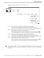
7 Programmer
W,X
SP.01
SP.02
SP.03
SP.04
W,X
W
Pt.01
Pt.02
Pt.03
Pt.04
t
Programmer set-up:
For using the controller as a programmer, select parameter SP.Fn = 1 in the
ConF menu. The programmer is started via one of digital inputs di2..3 or the è
key. Which input shall be used for starting the programmer is determined by selecting parameter P.run = 3 / 4 / 5 in the ConF menu accordingly.
For assigning the program end as a digital signal to one of the relay outputs, parameter P.End = 1 must be selected for the relevant output OUT.1...OUT.3 in the
ConF menu.
Programmer parameter setting:
A programmer with 4 segments is available to the user. Determine a segment duration Pt.01 .. Pt.04 (in minutes) and a segment target set-point SP.01 ..
SP.04 for each segment in the PArA menu.
Starting/stopping the programmer:
Starting the programmer is done by a digital signal at input di2..3 or by pressing
the è key selected by parameter P.run .
The programmer calculates a gradient from segment end setpoint and segment
time. This gradient is always valid. Normaly, the programmer starts the first segment at process value. Because of this the effective run-time of the first segment
may differ from the at PArA level setted segment time (process value ¹ setpoint).
After program end, the controller continues controlling with the target set-point
set last.
If the program is stopped during execution (signal at digital input di2..3 or the è
key is taken away), the programmer returns to program start and waits for a new
start signal.
KS40-1 burner
30
Programmer
+ Program parameter changing while the program is running is possible.
Changing the segment time:
Changing the segment time leads to re-calculation of the required gradient. When
the segment time has already elapsed, starting with the new segment is done directly, where the set-point changes with a step.
Changing the segment end setpoint:
Changing the set-point leads to re-calculation of the required gradient, in order to
reach the new set-point during the segment rest time, whereby the required gradient polarity sign can change.
31
KS40-1 burner
8 Technical data
SUPPLEMENTARY INPUT INP2
INPUTS
PROCESS VALUE INPUT INP1
Resolution:
Decimal point:
Dig. input filter:
Scanning cycle:
Measured value
correction:
> 14 bits
0 to 3 digits behind the
decimal point
adjustable 0,000...9999 s
100 ms
2-point or offset correction
r Table 2 (page 58 )
Input resistance:
Effect of source resistance:
³ 1 MW
1 mV/W
Cold-junction compensation
Maximal additional error:
Current measuring range
Technical data as for INP1
Potentiometer
r Table 2 (page 58 )
Sensor current:
Configurable output action
3-wire
max. 30 Ohm
break
CONTROL INPUT DI2/DI3
± 0,5 K
Configurable as switch or push-button!
Connection of a potential-free contact suitable
for switching “dry” circuits.
£ 1 mA
Switched voltage:
Current:
Sensor break monitoring
Resistance thermometer
r Table 2 (page 58 )
2 or 3-wire
max. 30 Ohm
break and short circuit
Current and voltage signals
r Table 3 (page 58 )
Span start, end of span: anywhere within measuring
range
Scaling:
selectable -1999...9999
Linearization:
16 segments, adaptable
with BlueControl
Decimal point:
adjustable
Input circuit monitor:
12,5% below span start
(2mA, 1V)
5V
160 mA
TRANSMITTER SUPPLY UT (OPTION)
22 mA / ³ 18 V
Power:
Potentiometric transducer 50-30-50 W
KS40-1 burner
> 14 bits
100 ms
< 0,5 %
Connection:
Lead resistance:
Input circuit monitor:
Thermocouples
Connection:
Lead resistance:
Input circuit monitor:
Resolution:
Scanning cycle:
Accuracy:
GALVANIC ISOLATION
Safety isolation
Function isolation
Power supply
connections
Relay outputs OUT 1,2
Relay output OUT3
32
Process value input INP1
Supplementary input INP2
Digital inputs di2, 3
Transmitter supply UT
OUTPUTS
ENVIRONMENTAL CONDITIONS
RELAY OUTPUTS OUT1, OUT2
Protection modes
Front panel:
IP 65 (NEMA 4X)
Housing:
IP 20
Terminals:
IP 00
Contact type:
2 NO contacts with
common connection
500 VA, 250 V, 2A at
48...62 Hz,
resistive load
6V, 1 mA DC
800.000 duty cycles with
max. rating
Max. contact rating:
Min. contact rating:
Operating life (electr.):
RELAY OUTPUT OUT3
Contact type:
potential-free changeover
contact
Max.contact rating:
500 VA, 250 V, 2A at 48...62
Hz,
resistive load
Min. contact rating:
5V, 10 mA AC/DC
Operating life (electr.): 600.000 duty cycles with
max. contact rating
Note:
If the relays OUT1...OUT3 operate external
contactors, these must be fitted with RC
snubber circuits to manufacturer specifications
to prevent excessive switch-off voltage peaks.
Permissible temperatures
For specified
0...60°C
accuracy:
Warm-up time:
³ 15 minutes
For operation:
-20...65°C
For storage:
-40...70°C
Humidity
75% yearly average, no condensation
Shock and vibration
Vibration test Fc (DIN 68-2-6)
Frequency:
10...150 Hz
Unit in operation:
1g or 0,075 mm
Unit not in operation: 2g or 0,15 mm
Shock test Ea (DIN IEC 68-2-27)
Shock:
Duration:
15g
11ms
Electromagnetic compatibility
POWER SUPPLY
Complies with EN 61 326-1
(for continuous, non-attended operation)
AC SUPPLY
Voltage:
Frequency:
Power consumption
90...260 V AC
48...62 Hz
approx. 7,0 VA
BEHAVIOUR WITH POWER FAILURE
Configuration, parameters and adjusted
set-points, control mode:
Non-volatile storage in EEPROM
33
KS40-1 burner
GENERAL
Housing
Material:
Flammability class:
Makrolon 9415
flame-retardant
UL 94 VO, self-extinguishing
Plug-in module, inserted from the front
Safety test
Complies with EN 61010-1 (VDE 0411-1):
Overvoltage category II
Contamination class 2
Working voltage range 300 V
Protection class II
Certifications
Type tested to EN 14597 (replaces DIN
3440)
With certified sensors applicable for:
w Heat generating plants with outflow
temperatures up to 120°C to DIN 4751
w Hot-water plants with outflow temperatures
above 110°C to DIN 4752
w Thermal transfer plants with organic transfer
media to DIN 4754
w Oil-heated plants to DIN 4755
cULus-certification
(Type 1, indoor use)
File: E 208286
Electrical connections
Flat-pin connectors 1 x 6,3 mm or 2 x 2,8 mm
to DIN 46 244
Mounting
Panel mounting with two fixing clamps at
top/bottom or right/left,
High-density mounting possible
Mounting position: uncritical
Weight:
0,27kg
Accessories delivered with the unit
Operating manual
Fixing clamps
KS40-1 burner
34
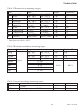
Technical data
Table 1 Thermocouples measuring ranges
Type
L
J
K
N
S
R
T
C
D
E
B*
Fe-CuNi (DIN)
Fe-CuNi
NiCr-Ni
Nicrosil/Nisil
PtRh-Pt 10%
PtRh-Pt 13%
Cu-CuNi
W5%Re-W26%Re
W3%Re-W25%Re
NiCr-CuNi
PtRh-Pt6%
Range
-100...900°C
-100...1200°C
-100...1350°C
-100...1300°C
0...1760°C
0...1760°C
-200...400°C
0...2315°C
0...2315°C
-100...1000°C
0(100)...1820°C
-148...1652°F
-148...2192°F
-148...2462°F
-148...2372°F
32...3200°F
32...3200°F
-328...752°F
32...4199°F
32...4199°F
-148...1832°F
32(212)...3308°F
Accuracy
ß 2K
ß 2K
ß 2K
ß 2K
ß 2K
ß 2K
ß 2K
ß 2K
ß 2K
ß 2K
ß 2K
Resolution (Ô)
0,1 K
0,1 K
0,2 K
0,2 K
0,2 K
0,2 K
0,05 K
0,4 K
0,4 K
0,1 K
0,3 K
* Specifications valid for 100°C
Table 2 Resistance transducer measuring ranges
Type
Sensor current
Pt100
Pt100
Pt1000
KTY 11-6 *
0,2 mA
Spezial
Spezial
Poti
Poti
Poti
* Or special
Range
-200...100°C
-200...850°C
-200...200°C
-50...150°C
Accuracy
ß 1K
ß 1K
ß 2K
ß 2K
-140...212°F
-140...1562°F
-140...392°F
-58...302°F
0...4500
0...450
0...160
0...450
0...1600
ß 0,1 %
Resolution (Ô)
0,1K
0,1K
0,1K
0,05K
0,01 %
Table 3 Current and voltage measuring ranges
Range
0-10 Volt
0-20 mA
Input resistance
~ 110 kW
49 W (voltage requirement ß 2,5 V)
Accuracy
ß 0,1 %
ß 0,1 %
35
Resolution (Ô)
ß 0,6 mV
ß 1,5 mA
KS40-1 burner
Safety hints
9 Safety hints
This unit was built and tested in compliance with VDE 0411-1 / EN 61010-1 and
was delivered in safe condition.
The unit complies with European guideline 89/336/EWG (EMC) and is provided
with CE marking.
The unit was tested before delivery and has passed the tests required by the test
schedule. To maintain this condition and to ensure safe operation, the user must
follow the hints and warnings given in this operating manual.
The unit is intended exclusively for use as a measurement and control instrument
in technical installations.
a IfWarning
the unit is damaged to an extent that safe operation seems impossible, the unit
must not be taken into operation.
ELECTRICAL CONNECTIONS
The electrical wiring must conform to local standards (e.g. VDE 0100). The input
measurement and control leads must be kept separate from signal and power
supply leads.
COMMISSIONING
Before instrument switch-on, check that the following information is taken into
account:
w Ensure that the supply voltage corresponds to the specifications on the type
label.
w All covers required for contact protection must be fitted.
w If the controller is connected with other units in the same signal loop, check
that the equipment in the output circuit is not affected before switch-on. If
necessary, suitable protective measures must be taken.
w The unit may be operated only in installed condition.
w Before and during operation, the temperature restrictions specified for
controller operation must be met.
w
SHUT-DOWN
For taking the unit out of operation, disconnect it from all voltage sources and
protect it against accidental operation.
If the controller is connected with other equipment in the same signal loop, check
that other equipment in the output circuit is not affected before switch-off. If necessary, suitable protective measures must be taken.
KS40-1 burner
36
Safety hints
MAINTENANCE, REPAIR AND MODIFICATION
The units do not need particular maintenance.
Warning
a When
opening the units, or when removing covers or components, live parts and
terminals may be exposed.
Before starting this work, the unit must be disconnected completely.
After completing this work, re-shut the unit and re-fit all covers and components.
Check if specifications on the type label must be changed and correct them, if necessary.
l
Caution
When opening the units, components which are sensitive to electrostatic discharge (ESD) can be exposed. The following work may be done only at workstations
with suitable ESD protection.
Modification, maintenance and repair work may be done only by trained and authorized personnel. For this purpose, the PMA service should be contacted.
37
KS40-1 burner
Safety hints
9.1 Resetting to factory setting
In case of faultyconfiguration, KS4x-1 can be reset to the default condition.
For this, the operator must keep the keys increment and decrement pressed during
power-on.
Then, press key increment to select YES.
Confirm factory resetting with Enter and the copy procedure is started
(display COPY).
Afterwards the device restarts.
1
2
3
ÌÈ + Power on
È
Ù
SP.x
FAC
torY
1.
run
SP.x
Ada
Err
FAC
no
run
Ada
Err
SP.x
FAC
YES
run
SP.x
Ada
Err
4
FAC
COPY
run
Ada
Err
8.8.8.8.
SP.x
8.8.8.8.
run
Ada
Err
2.
In all other cases, no reset will occur (timeout abortion).
g
If one of the operating levels was blocked and the safety lock is open, reset to
factory setting is not possible.
g
If a pass number was defined (via BlueControl® ) and the safety lock is open, but
no operating level was blocked, enter the correct pass number when prompted in
3. A wrong pass number aborts the reset action.
g
The copy procedure ( COPY) can take some seconds.
Now, the transmitter is in normal operation.
KS40-1 burner
38
Resetting to factory setting
Index
0-9
M
2-point correction . . . . . . . . . . . . . 27
Maintenance manager . . . . . . . . . . . . 9
Manual tuning . . . . . . . . . . . . . 11 - 12
Mounting . . . . . . . . . . . . . . . . . . 5
C
Calibration (CAL) . . . . . . . . . . . . . 27
Calibration level (CAL) . . . . . . . . 27 - 29
Configuration with QUIC . . . . . . 14 - 17
Configuration without QUIC . . . . . . . 18
Control inputs di1, di2, di3
Technical data . . . . . . . . . . . . . . 32
Current signal measuring range . . . . . . 32
O
Offset correction . . . . . . . . . . . . . . 27
Output OUT1
Technical data . . . . . . . . . . . . . . 33
Output OUT2
Technical data . . . . . . . . . . . . . . 33
D
P
Digital inputs di1, di2, di3
Technical data . . . . . . . . . . . . . . 32
Programmer
Changing segment end setpoint .
Changing segment time . . . . .
Parameter setting . . . . . . . .
Set-up . . . . . . . . . . . . . .
Starting/Stopping . . . . . . . .
E
Error list . . . . . . . . . . . . . . . . . . . 9
Example
3-point signaller . . . . . . . . . . . . . 16
3-point stepping controller . . . . . . . 17
Signaller with switch-over contact . . . 15
.
.
.
.
.
.
.
.
.
.
.
.
.
.
.
.
.
.
.
.
31
31
30
30
30
Q
QUIC Codes . . . . . . . . . . . . . . . . 14
F
R
Front view . . . . . . . . . . . . . . . . . . 7
Resetting to factory setting. . . . . . . . . 38
Resistance thermometer measuring range . 32
I
Input INP1
Parameters. . .
Technical data .
Input INP2
Parameters. . .
Input scaling . . .
S
. . . . . . . . . . . . . 25
. . . . . . . . . . . . . 32
. . . . . . . . . . . . . 25
. . . . . . . . . . . . . 26
L
LED
Ada - LED
Err - LED .
ì - LED .
ò - LED .
run - LED .
SP.x - LED
.
.
.
.
.
.
.
.
.
.
.
.
.
.
.
.
.
.
.
.
.
.
.
.
.
.
.
.
.
.
.
.
.
.
.
.
.
.
.
.
.
.
.
.
.
.
.
.
.
.
.
.
.
.
.
.
.
.
.
.
.
.
.
.
.
.
.
.
.
.
.
.
.
.
.
.
.
.
.
.
.
.
.
.
.
.
.
.
.
.
.
.
.
.
.
.
7
7
7
7
7
7
Safety hints . . . . . . . . . . . . . . 36 - 38
Safety switch . . . . . . . . . . . . . . . . 5
Safety test . . . . . . . . . . . . . . . . . 34
Self-tuning
Cancelation . . . . . . . . . . . . . 10 - 11
Cancelation causes . . . . . . . . . . . 11
Start . . . . . . . . . . . . . . . . . . . 10
T
Thermocouple measuring range . . . . . . 32
V
Voltage signal measuring range . . . . . . 32
39
KS40-1 burner
Subject to alterations without notice
Änderungen vorbehalten
Sous réserve de toutes modifications
© PMA Prozeß- und Maschinen-Automation GmbH
P.O.B. 310 229, D-34058 Kassel, Germany
Printed in Germany 9499-040-66011 (05/2009)
A6
A5 auf A6 gefaltet, 2-fach geheftet, SW-Druck Normalpapier weiß 80g/m2
9499- 040- 66011