1
INSTRUCTION MANUAL
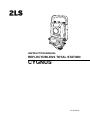
REFLECTORLESS TOTAL STATION
CYGNUS
71013 90010
FOREWORD
Thank you for purchasing the Reflectorless Total Station, CYGNUS.
For the best performance of the instruments, please carefully read these instructions
and keep them in a convenient location for future reference.
1
General Handling Precautions
Before starting work or operation, be sure to check that the instrument is
functioning correctly with normal performance.
Do not submerge the instrument into water.
The instrument can not be submerged underwater.
The instrument is designed based on the International Standard IP54, therefore it is
protected from the splashing water.
Setting the instrument on a tripod
When mounting the instrument on a tripod, use a wooden tripod when possible. The
vibrations that may occur when using a metallic tripod can effect the measuring precision.
Installing the tribrach
If the tribrach is installed incorrectly, the measuring precision could be effected.
Occasionally check the adjusting screws on the tribrach. Make sure the base fixing lever is
locked and the base fixing screws are tightened.
Guarding the instrument against shocks
When transporting the instrument, provide some protection to minimize risk of shocks.
Heavy shocks may cause the measurement to be faulty.
Carrying the instrument
Always carry the instrument by its handgrip.
Exposing the instrument to extreme heat.
Do not leave the instrument in extreme heat for longer than necessary. It could adversely
affect its performance.
Sudden changes of temperature
Any sudden change of temperature to the instrument or prism may result in a reduction of
measuring distance range, i.e when taking the instrument out from a heated vehicle. Let
instrument acclimate itself to ambient temperature.
Battery level check
Confirm battery level remaining before operating.
Do not hold the lower part of display unit
When you take out the instrument from a carrying case, or keep into the case, please hold
the hand grip and base of the instrument. Please do not hold the lower part of the display
unit.
External power source
Use only recommended batteries. Use of batteries not recommended by us may result in
equipment failure.
(For further information see the chapter 'BATTERY SYSTEM.')
2
Display for Safe Use
In order to encourage the safe use of products and prevent any danger to the operator and
others or damage to properties, important warnings are put on the products and inserted in the
instruction manuals.
We suggest that everyone understand the meaning of the following displays and icons before
reading the “Safety Cautions” and text.
Display
WARNING
CAUTION
Meaning
Ignoring or disregard of this display may lead to the danger of death or
serious injury.
Ignoring or disregard of this display may lead to personal injury or physical damage.
• Injury refers to hurt, burn, electric shock, etc.
• Physical damage refers to extensive damage to buildings or equipment and furniture.
Safety Cautions
WARNING
• There is a risk of fire, electric shock or physical harm if you attempt to disassemble or repair
the instrument yourself.
This is only to be carried out by an authorized dealer, only!
• Cause eye injury or blindness.
Do not look at the sun through a telescope.
• High temperature may cause fire.
Do not cover the charger while it is charging.
• Risk of fire or electric shock.
Do not use damaged power cable, plug and socket.
• Risk of fire or electric shock.
Do not use a wet battery or charger.
• May ignite explosively.
Do not use the unit in areas exposed to high amounts of dust or ash, in areas where there is inadequate ventilation,
or near combustible materials. An explosion could occur.
• Battery can cause explosion or injury.
Do not dispose in fire or heat.
• Risk of fire or electric shock.
Do not use any power voltage except the one given on manufacturers instructions.
• Battery can cause outbreak of fire.
Do not use any other type of charger other than the one specified.
• Risk of fire or electric shock.
Do not use an AC cable incompatible with the power supply voltage in use.
• The short circuit of a battery can cause a fire.
Do not short circuit battery when storing it.
3
CAUTION
• Use of controls or adjustment or performance of procedures other than those specified herein may result in hazardous radiation exposure.
• Do not connect or disconnect equipment with wet hands, you are at risk of electric shocks if you do!
• Risk of injury by overturn the carrying case.
Do not stand or sit on the carrying cases.
• Please note that the tips of tripod can be hazardous, be aware of this when setting up or carrying the tripod.
• Risk of injury by falling down the instrument or case.
Do not use a carrying case with a damaged grips or latches.
• Do not allow skin or clothing to come into contact with acid from the batteries, if this does occur then wash off with
copious amounts of water and seek medical advice.
• A plumb bob can cause an injury to a person if used incorrectly.
• It could be dangerous if the instrument falls over, please ensure you attach a hand grip to the instrument securely.
• Ensure that you mount the Tribrach correctly, failing to do so may result in injury if the tribrach were to fall over.
• It could be dangerous if the instrument falls over, please check that you fix the instrument to the tripod correctly.
• Risk of injury by falling down a tripod and an instrument.
Always check that the screws of tripod are tightened.
• The battery is to be disposed of safely.
• The appliance is not intended for use by young children or infirm persons without supervision.
Young children should be supervised to ensure that they do not play with the appliance.
4
User
1)This product is for professional use only!
The user is required to be a qualified surveyor or have a good knowledge of surveying, in order to
understand the user and safety instructions, before operating, inspecting or adjusting.
2)Wear the required protectors (safety shoes, helmet, etc.) when operating.
Exceptions from Responsibility
1)The user of this product is expected to follow all operating instructions and make periodic checks of the
product’s performance.
2)The manufacturer, or its representatives, assumes no responsibility for results of a faulty or intentional
usage or misuse including any direct, indirect, consequential damage, and loss of profits.
3)The manufacturer, or its representatives, assumes no responsibility for consequential damage, and
loss of profits by any disaster, (an earthquake, storms, floods etc.).
A fire, accident, or an act of a third party and/or a usage any other usual conditions.
4)The manufacturer, or its representatives, assumes no responsibility for any damage, and loss of profits
due to a change of data, loss of data, an interruption of business etc., caused by using the product or
an unusable product.
5)The manufacturer, or its representatives, assumes no responsibility for any damage, and loss of profits
caused by usage except for explained in the user manual.
6)The manufacturer, or its representatives, assumes no responsibility for damage caused by wrong
movement, or action due to connecting with other products.
5
Laser Safety
CYGNUS is classified as the following class of Laser Product according to IEC Standard Publication
60825-1 Ed.2.0: 2007 and United States Government Code of Federal Regulation FDA CDRH 21CFR
Part 1040.10 and 1040.11 (Complies with FDA performance standards for laser products except for
deviations pursuant to Laser Notice No.50, dated June 24, 2007.)
z EDM device in objective lens:
z When using prism:
Class 3R Laser Product
Class 2 Laser Product
EDM device is classified as Class 3R Laser Product when reflectorless measurement is selected.
When the prism is selected as target, the output is equivalent to the safer class 2.
CWARNING
z Use of controls or adjustments or performance of procedures other than those specified herein may
result in hazardous radiation exposure.
z Follow the safety instructions on the labels attached to the instrument as well as in this manual to
ensure safe use of this laser product.
ࠩశߩญ
AVOID EXPOSURE-Laser radiation
is emitted from this aperture.
Laser beam
emitted
from here
ࠩశ
⋡߳ߩ⋥ធⵍ߫ߊࠍㆱߌࠆߎߣ
/#:O9.&PO
ࠢࠬ4ࠩຠ
,+5%
LASER RADIATION
AVOID DIRECT EYE EXPOSURE
MAX 5mW LD 625-695nm
CLASS3R LASER PRODUCT
IEC 60825-1 Ed. 2.0 : 2007
z Never point the laser beam at another person. If the laser beam strikes skin or an eye, it could
cause serious injury.
z Do not look directly into the laser beam source. Doing so could cause permanent eye damage.
z Do not stare at the laser beam. Doing so could cause permanent eye damage.
z If an eye injury is caused by exposure to the laser beam, seek immediate medical attention from a
licensed ophthalmologist.
z Never look at the laser beam through a telescope, binoculars or other optical instruments. Doing so
could cause permanent eye damage.
z Sight the targets so that laser beam does not stray from them.
CCAUTION
z Perform checks at start of work and periodic checks and adjustments with the laser beam emitted
under normal conditions.
z When the instrument is not being used, turn off the power.
z When disposing of the instrument, destroy the battery connector so that the laser beam cannot be
emitted.
z Operate the instrument with due caution to avoid injuries that may be caused by the laser beam
unintentionally striking a person in the eye. Avoid setting the instrument at heights at which the path
of the laser beam may strike pedestrians or drivers at head height.
z Never point the laser beam at mirrors, windows or surfaces that are highly reflective. The reflected
laser beam could cause serious injury.
6
z When using the Laser-pointer function, be sure to turn OFF the output laser after distance
measurement is completed. Even if distance measurement is canceled, the Laser-pointer function
is still operating and the laser beam continues to be emitted.
z Only those who have been received training as per the following items shall use this product.
z Read the Instruction manual for usage procedures for this product.
z Hazardous protection procedures. (read "Laser Safety")
z Requisite protective gear. (read "Laser Safety")
z Accident reporting procedures (stipulate procedures beforehand for transporting the injured and
contacting physicians in case there are laser induced injuries).
z Persons working within the range of the laser beam are advised to wear eye protection which
corresponds to the laser wavelength of the instrument being used.
z Areas in which the lasers are used should be posted with laser warning notices.
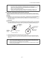
Symbol mark while the laser is emitting.
The following symbol mark will appear at the
right side of the second line.
TILT SENSOR:[XY-ON]
X:-0°00'25"
Y: 0°00'20"
X-ON XY-ON OFF L.PL
7
Symbol mark
Contents
FOREWORD . . . . . . . . . . . . . . . . . . . . . . . . . . . . . . . . . . . . . . . . . . . . . . . . . . 1
General Handling Precautions. . . . . . . . . . . . . . . . . . . . . . . . . . . . . . . . . . . . . . . . . . . . . . . .2
Display for Safe Use . . . . . . . . . . . . . . . . . . . . . . . . . . . . . . . . . . . . . . . . . . . . . . . . . . . . . . .3
Safety Cautions . . . . . . . . . . . . . . . . . . . . . . . . . . . . . . . . . . . . . . . . . . . . . . . . . . . . . . . . . . . .3
User . . . . . . . . . . . . . . . . . . . . . . . . . . . . . . . . . . . . . . . . . . . . . . . . . . . . . . . . . . . . . . . . . . . . .5
Exceptions from Responsibility . . . . . . . . . . . . . . . . . . . . . . . . . . . . . . . . . . . . . . . . . . . . . . . .5
Laser Safety. . . . . . . . . . . . . . . . . . . . . . . . . . . . . . . . . . . . . . . . . . . . . . . . . . . . . . . . . . . . . . .6
Symbol mark while the laser is emitting. . . . . . . . . . . . . . . . . . . . . . . . . . . . . . . . . . . . . . . . . .7
Standard Set Composition. . . . . . . . . . . . . . . . . . . . . . . . . . . . . . . . . . . . . . . . . . . . . . . . . . .11
1 NOMENCLATURE AND FUNCTIONS . . . . . . . . . . . . . . . . . . . . . . . . . . . 1-1
1.1
1.2
1.3
1.4
1.5
1.6
Nomenclature . . . . . . . . . . . . . . . . . . . . . . . . . . . . . . . . . . . . . . . . . . . . . . . . . . . . . . . . 1-1
Display . . . . . . . . . . . . . . . . . . . . . . . . . . . . . . . . . . . . . . . . . . . . . . . . . . . . . . . . . . . . . 1-3
Operating Key. . . . . . . . . . . . . . . . . . . . . . . . . . . . . . . . . . . . . . . . . . . . . . . . . . . . . . . . 1-4
Function Key (Soft Key) . . . . . . . . . . . . . . . . . . . . . . . . . . . . . . . . . . . . . . . . . . . . . . . . 1-5
Star key mode. . . . . . . . . . . . . . . . . . . . . . . . . . . . . . . . . . . . . . . . . . . . . . . . . . . . . . . . 1-7
Serial signal RS-232C connector . . . . . . . . . . . . . . . . . . . . . . . . . . . . . . . . . . . . . . . . . 1-9
2 PREPARATION FOR MEASUREMENT . . . . . . . . . . . . . . . . . . . . . . . . . . 2-1
2.1
2.2
2.3
2.4
2.5
Setting Instrument Up For Measurement . . . . . . . . . . . . . . . . . . . . . . . . . . . . . . . . . . . 2-1
Power Switch Key ON . . . . . . . . . . . . . . . . . . . . . . . . . . . . . . . . . . . . . . . . . . . . . . . . . 2-2
Battery Power Remaining Display . . . . . . . . . . . . . . . . . . . . . . . . . . . . . . . . . . . . . . . . 2-3
Vertical Angle Tilt Correction . . . . . . . . . . . . . . . . . . . . . . . . . . . . . . . . . . . . . . . . . . . . 2-4
How to Enter Alphanumeric characters . . . . . . . . . . . . . . . . . . . . . . . . . . . . . . . . . . . . 2-6
2.5.1 How to Enter Alphanumeric Characters. . . . . . . . . . . . . . . . . . . . . . . . . . . . . . . . 2-6
3 ANGLE MEASUREMENT . . . . . . . . . . . . . . . . . . . . . . . . . . . . . . . . . . . . . 3-1
3.1 Measuring Horizontal Angle Right and Vertical Angle . . . . . . . . . . . . . . . . . . . . . . . . . 3-1
3.2 Switching Horizontal Angle Right/Left. . . . . . . . . . . . . . . . . . . . . . . . . . . . . . . . . . . . . . 3-2
3.3 Measuring from the Required Horizontal Angle . . . . . . . . . . . . . . . . . . . . . . . . . . . . . . 3-2
3.3.1 Setting by Holding the Angle . . . . . . . . . . . . . . . . . . . . . . . . . . . . . . . . . . . . . . . . 3-2
3.3.2 Setting a Horizontal Angle from the Keys . . . . . . . . . . . . . . . . . . . . . . . . . . . . . . 3-3
3.4 Vertical Angle Percent Grade(%) Mode . . . . . . . . . . . . . . . . . . . . . . . . . . . . . . . . . . . . 3-3
3.5 Repetition Angle Measurement . . . . . . . . . . . . . . . . . . . . . . . . . . . . . . . . . . . . . . . . . . 3-4
3.6 Buzzer Sounding for Horizontal Angle 90° Increments . . . . . . . . . . . . . . . . . . . . . . . . 3-5
3.7 Compasses (vertical angle) . . . . . . . . . . . . . . . . . . . . . . . . . . . . . . . . . . . . . . . . . . . . . 3-6
4 DISTANCE MEASUREMENT . . . . . . . . . . . . . . . . . . . . . . . . . . . . . . . . . . 4-1
4.1
4.2
4.3
4.4
4.5
4.6
4.7
Setting of the Atmospheric Correction . . . . . . . . . . . . . . . . . . . . . . . . . . . . . . . . . . . . . 4-1
Setting of the Correction for Prism Constant / Non-prism Constant . . . . . . . . . . . . . . . 4-1
Distance Measurement (Continuous Measurement) . . . . . . . . . . . . . . . . . . . . . . . . . . 4-2
Distance Measurement (N-time Measurement/Single Measurement) . . . . . . . . . . . . . 4-3
Fine Mode/Tracking Mode/Coarse Mode . . . . . . . . . . . . . . . . . . . . . . . . . . . . . . . . . . . 4-4
Stake Out (S.O) . . . . . . . . . . . . . . . . . . . . . . . . . . . . . . . . . . . . . . . . . . . . . . . . . . . . . . 4-5
Offset Measurement . . . . . . . . . . . . . . . . . . . . . . . . . . . . . . . . . . . . . . . . . . . . . . . . . . . 4-6
4.7.1 Angle Offset . . . . . . . . . . . . . . . . . . . . . . . . . . . . . . . . . . . . . . . . . . . . . . . . . . . . . 4-7
4.7.2 Distance Offset Measurement . . . . . . . . . . . . . . . . . . . . . . . . . . . . . . . . . . . . . . . 4-9
4.7.3 Plane Offset Measurement . . . . . . . . . . . . . . . . . . . . . . . . . . . . . . . . . . . . . . . . 4-11
4.7.4 Column Offset Measurement . . . . . . . . . . . . . . . . . . . . . . . . . . . . . . . . . . . . . . . 4-13
5 COORDINATE MEASUREMENT . . . . . . . . . . . . . . . . . . . . . . . . . . . . . . . 5-1
5.1
5.2
5.3
5.4
Setting Coordinate Values of Occupied Point. . . . . . . . . . . . . . . . . . . . . . . . . . . . . . . . 5-1
Setting Height of the Instrument . . . . . . . . . . . . . . . . . . . . . . . . . . . . . . . . . . . . . . . . . . 5-2
Setting Height of Target (Prism Height) . . . . . . . . . . . . . . . . . . . . . . . . . . . . . . . . . . . . 5-2
Execution of Coordinate Measuring . . . . . . . . . . . . . . . . . . . . . . . . . . . . . . . . . . . . . . . 5-3
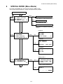
6 SPECIAL MODE (Menu Mode). . . . . . . . . . . . . . . . . . . . . . . . . . . . . . . . . 6-1
6.1 Application Measurement (PROGRAMS) . . . . . . . . . . . . . . . . . . . . . . . . . . . . . . . . . . 6-2
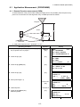
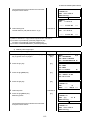
6.1.1 Remote Elevation measurement (REM) . . . . . . . . . . . . . . . . . . . . . . . . . . . . . . . 6-2
6.1.2 Missing Line Measurement (MLM). . . . . . . . . . . . . . . . . . . . . . . . . . . . . . . . . . . . 6-5
6.1.3 Setting Z Coordinate of Occupied Point. . . . . . . . . . . . . . . . . . . . . . . . . . . . . . . . 6-8
6.1.4 Area Calculation. . . . . . . . . . . . . . . . . . . . . . . . . . . . . . . . . . . . . . . . . . . . . . . . . 6-11
6.1.5 Point to Line Measurement . . . . . . . . . . . . . . . . . . . . . . . . . . . . . . . . . . . . . . . . 6-14
6.2 Setting the GRID FACTOR. . . . . . . . . . . . . . . . . . . . . . . . . . . . . . . . . . . . . . . . . . . . . 6-16
6.3 Setting Illumination of Display . . . . . . . . . . . . . . . . . . . . . . . . . . . . . . . . . . . . . . . . . . 6-17
6.4 Setting Mode 1 . . . . . . . . . . . . . . . . . . . . . . . . . . . . . . . . . . . . . . . . . . . . . . . . . . . . . . 6-18
8
6.4.1 Setting Minimum Reading . . . . . . . . . . . . . . . . . . . . . . . . . . . . . . . . . . . . . . . . . 6-18
6.4.2 Auto Power Off. . . . . . . . . . . . . . . . . . . . . . . . . . . . . . . . . . . . . . . . . . . . . . . . . . 6-19
6.4.3 Vertical Angle Tilt correction (Tilt ON/OFF) . . . . . . . . . . . . . . . . . . . . . . . . . . . . 6-20
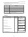
6.4.4 Setting RS-232C communication with external device . . . . . . . . . . . . . . . . . . . 6-21
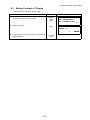
6.5 Setting Contrast of Display . . . . . . . . . . . . . . . . . . . . . . . . . . . . . . . . . . . . . . . . . . . . 6-22
6.6 ROAD . . . . . . . . . . . . . . . . . . . . . . . . . . . . . . . . . . . . . . . . . . . . . . . . . . . . . . . . . . . . . 6-23
6.6.1 Input Start Point . . . . . . . . . . . . . . . . . . . . . . . . . . . . . . . . . . . . . . . . . . . . . . . . . 6-24
6.6.2 Input Road Data. . . . . . . . . . . . . . . . . . . . . . . . . . . . . . . . . . . . . . . . . . . . . . . . . 6-25
6.6.3 Search Data . . . . . . . . . . . . . . . . . . . . . . . . . . . . . . . . . . . . . . . . . . . . . . . . . . . . 6-29
6.6.4 Edit Data . . . . . . . . . . . . . . . . . . . . . . . . . . . . . . . . . . . . . . . . . . . . . . . . . . . . . . 6-29
6.6.5 Set OCC and BS . . . . . . . . . . . . . . . . . . . . . . . . . . . . . . . . . . . . . . . . . . . . . . . . 6-30
6.6.6 Setout Road . . . . . . . . . . . . . . . . . . . . . . . . . . . . . . . . . . . . . . . . . . . . . . . . . . . . 6-32
6.6.7 Select a File . . . . . . . . . . . . . . . . . . . . . . . . . . . . . . . . . . . . . . . . . . . . . . . . . . . . 6-33
6.6.8 Initialize ROAD data. . . . . . . . . . . . . . . . . . . . . . . . . . . . . . . . . . . . . . . . . . . . . . 6-33
7 DATA COLLECTION. . . . . . . . . . . . . . . . . . . . . . . . . . . . . . . . . . . . . . . . . 7-1
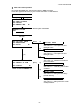
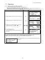
7.1 Preparation . . . . . . . . . . . . . . . . . . . . . . . . . . . . . . . . . . . . . . . . . . . . . . . . . . . . . . . . . . 7-3
7.1.1 Selecting a File for Data Collection . . . . . . . . . . . . . . . . . . . . . . . . . . . . . . . . . . . 7-3
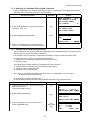
7.1.2 Selecting a Coordinate File for Data Collection . . . . . . . . . . . . . . . . . . . . . . . . . . 7-4
7.1.3 Occupied Point and Backsight Point . . . . . . . . . . . . . . . . . . . . . . . . . . . . . . . . . . 7-4
7.2 Operational Procedure of DATA COLLECT . . . . . . . . . . . . . . . . . . . . . . . . . . . . . . . . . 7-7
7.2.1 Searching the recorded data . . . . . . . . . . . . . . . . . . . . . . . . . . . . . . . . . . . . . . . . 7-8
7.2.2 Entering PCODE / ID using PCODE Library . . . . . . . . . . . . . . . . . . . . . . . . . . . . 7-8
7.2.3 Entering PCODE / ID from the list of PCODE . . . . . . . . . . . . . . . . . . . . . . . . . . . 7-9
7.3 Data Collect Offset Measurement mode. . . . . . . . . . . . . . . . . . . . . . . . . . . . . . . . . . . 7-10
7.3.1 Angle Offset Measurement . . . . . . . . . . . . . . . . . . . . . . . . . . . . . . . . . . . . . . . . 7-10
7.3.2 Distance Offset Measurement . . . . . . . . . . . . . . . . . . . . . . . . . . . . . . . . . . . . . . 7-12
7.3.3 Plane Offset Measurement . . . . . . . . . . . . . . . . . . . . . . . . . . . . . . . . . . . . . . . . 7-14
7.3.4 Column Offset Measurement . . . . . . . . . . . . . . . . . . . . . . . . . . . . . . . . . . . . . . . 7-16
7.4 NEZ Auto Calculation . . . . . . . . . . . . . . . . . . . . . . . . . . . . . . . . . . . . . . . . . . . . . . . . . 7-17
7.5 Point to Line Measurement. . . . . . . . . . . . . . . . . . . . . . . . . . . . . . . . . . . . . . . . . . . . . 7-18
7.5.1 To change to the point to line measurement . . . . . . . . . . . . . . . . . . . . . . . . . . . 7-18
7.5.2 Executing a point to line measurement . . . . . . . . . . . . . . . . . . . . . . . . . . . . . . . 7-19
7.6 Editing PCODE Library [PCODE INPUT] . . . . . . . . . . . . . . . . . . . . . . . . . . . . . . . . . . 7-20
7.7 Setting Parameter of Data Collect [CONFIG.] . . . . . . . . . . . . . . . . . . . . . . . . . . . . . . 7-21
8 LAYOUT . . . . . . . . . . . . . . . . . . . . . . . . . . . . . . . . . . . . . . . . . . . . . . . . . . 8-1
8.1 Preparation . . . . . . . . . . . . . . . . . . . . . . . . . . . . . . . . . . . . . . . . . . . . . . . . . . . . . . . . . . 8-3
8.1.1 Setting the GRID FACTOR . . . . . . . . . . . . . . . . . . . . . . . . . . . . . . . . . . . . . . . . . 8-3
8.1.2 Selecting Coordinate Data File . . . . . . . . . . . . . . . . . . . . . . . . . . . . . . . . . . . . . . 8-4
8.1.3 Setting Occupied Point . . . . . . . . . . . . . . . . . . . . . . . . . . . . . . . . . . . . . . . . . . . . 8-5
8.1.4 Setting Backsight Point . . . . . . . . . . . . . . . . . . . . . . . . . . . . . . . . . . . . . . . . . . . . 8-7
8.2 Executing a Layout . . . . . . . . . . . . . . . . . . . . . . . . . . . . . . . . . . . . . . . . . . . . . . . . . . . . 8-9
8.2.1 Layout of Coordinates of Point to Line . . . . . . . . . . . . . . . . . . . . . . . . . . . . . . . . 8-11
8.3 Setting a New Point . . . . . . . . . . . . . . . . . . . . . . . . . . . . . . . . . . . . . . . . . . . . . . . . . . 8-12
8.3.1 Side Shot Method . . . . . . . . . . . . . . . . . . . . . . . . . . . . . . . . . . . . . . . . . . . . . . . 8-12
8.3.2 Resection Method . . . . . . . . . . . . . . . . . . . . . . . . . . . . . . . . . . . . . . . . . . . . . . . 8-14
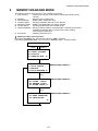
9 MEMORY MANAGER MODE . . . . . . . . . . . . . . . . . . . . . . . . . . . . . . . . . . 9-1
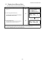
9.1 Display Internal Memory Status . . . . . . . . . . . . . . . . . . . . . . . . . . . . . . . . . . . . . . . . . . 9-2
9.2 Searching Data . . . . . . . . . . . . . . . . . . . . . . . . . . . . . . . . . . . . . . . . . . . . . . . . . . . . . . . 9-3
9.2.1 Measured Data Searching . . . . . . . . . . . . . . . . . . . . . . . . . . . . . . . . . . . . . . . . . . 9-3
9.2.2 Coordinate Data Searching . . . . . . . . . . . . . . . . . . . . . . . . . . . . . . . . . . . . . . . . . 9-5
9.2.3 PCODE LIBRARY Searching. . . . . . . . . . . . . . . . . . . . . . . . . . . . . . . . . . . . . . . . 9-6
9.3 FILE MAINTENANCE . . . . . . . . . . . . . . . . . . . . . . . . . . . . . . . . . . . . . . . . . . . . . . . . . . 9-7
9.3.1 Rename a File . . . . . . . . . . . . . . . . . . . . . . . . . . . . . . . . . . . . . . . . . . . . . . . . . . . 9-8
9.3.2 Searching Data in a File. . . . . . . . . . . . . . . . . . . . . . . . . . . . . . . . . . . . . . . . . . . . 9-8
9.3.3 Deleting a File . . . . . . . . . . . . . . . . . . . . . . . . . . . . . . . . . . . . . . . . . . . . . . . . . . . 9-9
9.4 Coordinate Data Direct Key Input . . . . . . . . . . . . . . . . . . . . . . . . . . . . . . . . . . . . . . . . 9-10
9.4.1 Coordinate data input . . . . . . . . . . . . . . . . . . . . . . . . . . . . . . . . . . . . . . . . . . . . 9-10
9.4.2 PTL (Point to Line) data input . . . . . . . . . . . . . . . . . . . . . . . . . . . . . . . . . . . . . . 9-11
9.5 Delete a Coordinate Data from a File . . . . . . . . . . . . . . . . . . . . . . . . . . . . . . . . . . . . . 9-12
9.6 Editing PCODE Library . . . . . . . . . . . . . . . . . . . . . . . . . . . . . . . . . . . . . . . . . . . . . . . . 9-13
9.7 Data Communications . . . . . . . . . . . . . . . . . . . . . . . . . . . . . . . . . . . . . . . . . . . . . . . . 9-14
9.7.1 Sending Data . . . . . . . . . . . . . . . . . . . . . . . . . . . . . . . . . . . . . . . . . . . . . . . . . . . 9-14
9.7.2 Loading Data . . . . . . . . . . . . . . . . . . . . . . . . . . . . . . . . . . . . . . . . . . . . . . . . . . . 9-15
9
9.7.3 Setting Parameter of Data Communications . . . . . . . . . . . . . . . . . . . . . . . . . . . 9-16
9.8 Initialization . . . . . . . . . . . . . . . . . . . . . . . . . . . . . . . . . . . . . . . . . . . . . . . . . . . . . . . . . 9-17
10 SET AUDIO MODE . . . . . . . . . . . . . . . . . . . . . . . . . . . . . . . . . . . . . . . . 10-1
11 SETTING THE PRISM / NON-PRISM CONSTANT VALUE . . . . . . . . . 11-1
12 SETTING ATMOSPHERIC CORRECTION. . . . . . . . . . . . . . . . . . . . . . 12-1
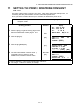
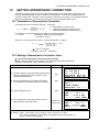
12.1 Calculation of Atmospheric Correction . . . . . . . . . . . . . . . . . . . . . . . . . . . . . . . . . . . 12-1
12.2 Setting of Atmospheric Correction Value . . . . . . . . . . . . . . . . . . . . . . . . . . . . . . . . . 12-1
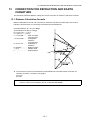
13 CORRECTION FOR REFRACTION AND EARTH CURVATURE . . . . 13-1
13.1 Distance Calculation Formula. . . . . . . . . . . . . . . . . . . . . . . . . . . . . . . . . . . . . . . . . . 13-1
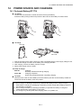
14 POWER SOURCE AND CHARGING . . . . . . . . . . . . . . . . . . . . . . . . . . 14-1
14.1 On-board Battery BT-77Q. . . . . . . . . . . . . . . . . . . . . . . . . . . . . . . . . . . . . . . . . . . . . 14-1
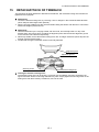
15 DETACH/ATTACH OF TRIBRACH. . . . . . . . . . . . . . . . . . . . . . . . . . . . 15-1
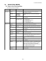
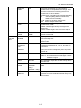
16 SELECTING MODE. . . . . . . . . . . . . . . . . . . . . . . . . . . . . . . . . . . . . . . . 16-1
16.1 Items of the Selecting Mode . . . . . . . . . . . . . . . . . . . . . . . . . . . . . . . . . . . . . . . . . . . 16-1
16.2 How to Set Selecting Mode . . . . . . . . . . . . . . . . . . . . . . . . . . . . . . . . . . . . . . . . . . . 16-3
17 CHECK AND ADJUSTMENT . . . . . . . . . . . . . . . . . . . . . . . . . . . . . . . . 17-1
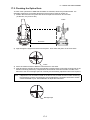
17.1 Checking and adjusting of instrument constant . . . . . . . . . . . . . . . . . . . . . . . . . . . . 17-1
17.2 Checking the Optical Axis. . . . . . . . . . . . . . . . . . . . . . . . . . . . . . . . . . . . . . . . . . . . . 17-2
17.3 Checking/Adjusting the Theodolite Functions. . . . . . . . . . . . . . . . . . . . . . . . . . . . . . 17-3
17.3.1 Checking /Adjusting the Plate Level . . . . . . . . . . . . . . . . . . . . . . . . . . . . . . . . 17-4
17.3.2 Checking /Adjusting the Circular Level . . . . . . . . . . . . . . . . . . . . . . . . . . . . . . 17-4
17.3.3 Adjustment of the Vertical Cross-hair . . . . . . . . . . . . . . . . . . . . . . . . . . . . . . . 17-5
17.3.4 Collimation of the Instrument . . . . . . . . . . . . . . . . . . . . . . . . . . . . . . . . . . . . . . 17-6
17.3.5 Checking / Adjusting the Optical Plummet Telescope . . . . . . . . . . . . . . . . . . . 17-7
17.3.6 Adjustment of Vertical Angle 0 Datum . . . . . . . . . . . . . . . . . . . . . . . . . . . . . . . 17-8
17.4 How to Set the Instrument Constant Value. . . . . . . . . . . . . . . . . . . . . . . . . . . . . . . . 17-9
18 PRECAUTIONS . . . . . . . . . . . . . . . . . . . . . . . . . . . . . . . . . . . . . . . . . . . 18-1
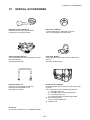
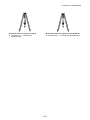
19 SPECIAL ACCESSORIES . . . . . . . . . . . . . . . . . . . . . . . . . . . . . . . . . . 19-1
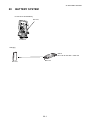
20 BATTERY SYSTEM . . . . . . . . . . . . . . . . . . . . . . . . . . . . . . . . . . . . . . . 20-1
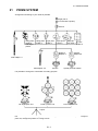
21 PRISM SYSTEM . . . . . . . . . . . . . . . . . . . . . . . . . . . . . . . . . . . . . . . . . . 21-1
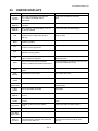
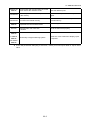
22 ERROR DISPLAYS . . . . . . . . . . . . . . . . . . . . . . . . . . . . . . . . . . . . . . . . 22-1
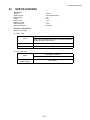
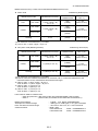
23 SPECIFICATIONS . . . . . . . . . . . . . . . . . . . . . . . . . . . . . . . . . . . . . . . . . 23-1
24 REGULATIONS . . . . . . . . . . . . . . . . . . . . . . . . . . . . . . . . . . . . . . . . . . . 24-1
APPENDIX ......................................................................................Appendix-1
10
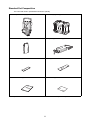
Standard Set Composition
The numerical value in parentheses shows the quantity.
CYGNUS (with lens cap) (1)
Plastic carrying case(1)
On-board Battery BT-77Q (1)
Battery charger BC-L1W (1),
Plastic rain cover(1)
Tool kit (1)
Instruction manual (1)
Silicon cloth (1)
(Make sure that all of the above items are with the instrument when purchased.)
11
1 NOMENCLATURE AND FUNCTIONS
1
NOMENCLATURE AND FUNCTIONS
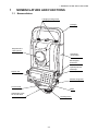
1.1 Nomenclature
Handgrip locking screw
Handgrip
Objective lens
Laser pointer
Laser aperture
Instrument
center mark
Serial Signal
Connector
Optical plummet
telescope
Display unit
Tribrach fixing lever
Circular level
Base
Adjustment screw
for circular level
Leveling screw
1-1
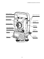
1 NOMENCLATURE AND FUNCTIONS
Sighting collimator
Battery locking button
Telescope focusing knob
Telescope grip
On-board battery
BT-77Q
Telescope eyepiece
Instrument
center mark
Vertical motion clamp
Vertical tangent screw
Horizontal
tangent screw
Plate level
Horizontal
motion clamp
Display unit
1-2
1 NOMENCLATURE AND FUNCTIONS
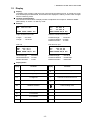
1.2 Display
z Display
The display uses a graphic LCD which has 4 lines and 20 characters per line. In general, the upper
three lines display measured data, and the bottom line displays the soft key function which changes
with the measuring mode.
z Contrast and Illumination
The contrast and illumination of display window are adjusted. See Chapter 6 “SPECIAL MODE
(Menu Mode)” or section 1.5 “Star key mode”.
z Example
V : 90°10'20"
HR: 120°30'40"
HR: 120°30'40"
HD*
65.432 m
VD:
12.345 m
MEAS MODE NP/P P1↓
0SET HOLD HSET P1↓
Angle measurement mode
Distance measurement mode
V-angle
H-angle
Horizontal-angle
: 120°30’40”
Horizontal distance : 65.432m
Relative elevation : 12.345m
: 90°10’20”
: 120°30’40”
Feet unit
Feet and inch unit
HR: 120°30'40"
HD* 123.45 f
VD:
12.34 f
MEAS MODE NP/P P1↓
HR: 120°30'40"
HD*
123.04.6f
VD:
12.03.4f
MEAS MODE NP/P P1↓
Horizontal-angle
: 120°30’40”
Horizontal distance : 123.45ft
Relative elevation : 12.34ft
Horizontal-angle
: 120°30’40”
Horizontal distance : 123ft4in6/8in
Relative elevation : 12ft3in4/8in
z Display marks
Display
Contents
Display
Contents
V
V-angle
∗
EDM working
HR
H-angle right
m
Meter unit
HL
H-angle left
f
Feet unit / Feet and inch unit
HD
Horizontal distance
VD
Relative elevation
SD
Slope distance
N
N coordinate
E
E coordinate
Z
Z coordinate
N
P
Switches non-prism mode or prism mode
Laser emitting mark
1-3
1 NOMENCLATURE AND FUNCTIONS
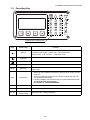
1.3 Operating Key
Alphanumeric characters key
Keys
Name of Key
Star key
Coordinate
meas.key
Distance meas.key
ANG
Angle meas.key
MENU
Menu key
ESC
Escape key
ENT
Enter key
POWER
Power source key
F1–F4
Soft key
(Function key)
Function
Star key mode is used for each presetting or displaying as follows.
1 Contrast of the display 2 Back Light 3 Non-prism/Prism
4 Laser pointer 5 Tilt correction 6 Set audio mode
Coordinate measurement mode
Distance measurement mode
Angle measurement mode
To be menu mode. To set application measurements and adjust in the
menu mode.
z Returning to the measurement mode or previous layer mode from the
mode set.
z To be DATA COLLECTION mode or LAYOUT mode directly from the
normal measurement mode.
z It is also possible to use as Record key in normal measurement mode.
To select function of Escape key,
see Chapter 16 “SELECTING MODE” .
Press at the end of inputting values.
ON/OFF of power source
Responds to the message displayed.
1-4
1 NOMENCLATURE AND FUNCTIONS
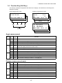
1.4 Function Key (Soft Key)
The Soft Key message is displayed at the bottom line of display. The functions are according to the
displayed message.
Angle measurement mode
Distance measurement mode
V: 90°10'20"
HR:120°30'40"
HR: 120°30'40"
HD*[r]
<< m
VD:
m
MEAS MODE NP/P P1↓
0SET HOLD HSET P1↓
TILT REP
V% P2↓
H-BZ R/L CMPS P3↓
OFSET S.O
S/A
--- m/f/i
P2↓
---
P3↓
Coordinates measurement mode
[F1]
[F2]
[F3]
N: 123.456 m
E: 34.567 m
Z: 78.912 m
MEAS MODE NP/P
[F4]
Soft keys
P1↓
R.HT INSHT OCC P2↓
OFSET m/f/i S/A P3↓
Angle measurement
Page
1
2
3
Soft
key
Display
mark
F1
0SET
F2
HOLD
Hold the horizontal angle.
F3
HSET
Sets a required horizontal angle by entering numerals.
F4
P1↓
The function of soft keys is shown on next page (P2).
F1
TILT
Setting Tilt Correction
If ON, the display shows tilt correction value.
F2
REP
Repetition angle measurement mode
F3
V%
Vertical angle percent grade(%) mode
F4
P2↓
The function of soft keys is shown on next page (P3).
F1
H-BZ
F2
R/L
F3
CMPS
F4
P3↓
Function
Angle of Horizontal is set to 0°00'00"
Sets the buzzer sound for every horizontal angle 90°.
Switches R/L rotation of horizontal angle.
Switches the COMPASS ON/OFF of vertical angle.
The function of soft keys is shown on next page (P1).
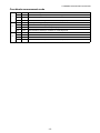
Distance measurement mode
1
F1
MEAS
Start measuring
F2
MODE
Sets a measuring mode, Fine/Coarse/Tracking.
F3
NP/P
Switches non-prism mode or prism mode.
F4
P1↓
The function of soft keys is shown on next page (P2).
F1
2
3
OFSET Select Off-set measurement mode.
F2
S.O
Select stake out measurement mode.
F3
S/A
Select set audio mode.
F4
P2↓
The function of soft keys is shown on next page (P3).
F2
m/f/i
Switches meter, feet or feet and inch unit.
F4
P3↓
The function of soft keys is shown on next page (P1).
1-5
1 NOMENCLATURE AND FUNCTIONS
Coordinate measurement mode
1
2
F1
MEAS
F2
MODE
F3
NP/P
Switches non-prism mode or prism mode.
The function of soft keys is shown on next page (P2).
Sets a measuring mode, Fine/Coarse/Tracking.
F4
P1↓
F1
R.HT
F2
INSHT
F3
OCC
Sets an instrument coordinate point by input values.
F4
P2↓
The function of soft keys is shown on next page (P3).
F1
3
Start measuring.
Sets a prism height by input values.
Sets an instrument height by input values.
OFSET Select Off-set measurement mode.
F2
m/f/i
Switches meter, feet or feet and inch unit.
F3
S/A
Select set audio mode.
F4
P3↓
The function of soft keys is shown on next page (P1).
1-6
1 NOMENCLATURE AND FUNCTIONS
1.5 Star key mode
Press the () key to view the instrument options.
The following instrument options can be selected from the ():
1.Adjustment the contrast of the display (0 to 9 steps) [
or
]
2.Turn the backlight of the display, reticle illumination ON / OFF
3.Select Non-prism mode / Prism mode
4.Turn the Laser pointer option ON/Blink/OFF
5. Setting Tilt Correction
6.S/A (set audio) mode
Note: Star key mode does not function when the same function as the function assigned to the star
key mode is performed from the main routine.
V: 77°42'30"
HR:120°30'40"
0SET HOLD HSET P1↓
Press the star () key.
Press the star () key.
key
Display
mark
Function
F1
Turn the backlight of the display ON/OFF [
F2
Non-prism mode / Prism mode selection
F3
Turn the Laser pointer option ON / OFF [
F1
---
F2
F3
F4
or
---
/
/
]
]
---Setting Tilt Correction
If ON, the display shows tilt correction value.
---The light acceptance quantity level for the EDM (SIGNAL), the
atmospheric correction value (PPM) and correction value of prism
constant (PSM) are displayed.
Adjust the contrast of the display (0 to 9 steps)
1-7
1 NOMENCLATURE AND FUNCTIONS
z Adjustment the contrast (0 to 9 ) of the display
This enable you to adjust the contrast of the display.
Press the up or down arrow keys to adjust the contrast.
z Turn the display backlight ON/OFF
To turn the backlight ON, press the [F1] key. Press [F1] again to turn the backlight OFF.
z Switching the non-prism mode/prism mode
To switch the non-prism /prism mode, press the [F2](NP/P) key. For more information, see Chapter
4 “DISTANCE MEASUREMENT” .
z Lighting and Extinguishing of Laser Pointer
Whenever the [F3] (L.P.) key is pressed, the laser pointer will light up or be extinguished, in that
order. The laser pointer assists with collimation by radiating visible laser light from the objective lens
to the target.
Laser aperture
z You cannot see the laser pointer when looking through the telescope. Therefore, please
look directly, with the naked eye, at the point indicated by the laser pointer.
z The distance to which the laser pointer can be used will vary with climatic conditions and
with the eyesight of the user.
z When the laser pointer is used, the operating time of internal power source will become
short.
z Tilt correction
The tilt setting mode performed here will not be memorized after powering OFF. To set TILT
correction in the initialized setting (it is memorized after powering OFF), see Section 6.4.3 “Vertical
Angle Tilt correction (Tilt ON/OFF)”.
z Set audio mode
The light acceptance quantity level (Signal level) is displayed in this mode.
When reflected light from the prism is received, a buzzer sounds. This function is good for easy
collimation when the target is difficult to find.
Press the [F4] key to view the set audio screen.
(1) To stop the buzzer, refer to Chapter 16 “SELECTING MODE”.
(2) Also, it is possible to display the signal level in Distance Measuring Mode.
The temperature, pressure, PPM, PSM and NPM can be viewed in set audio mode.
Refer to Chapter 10 “SET AUDIO MODE”, Chapter 11 “SETTING THE PRISM / NON-PRISM
CONSTANT VALUE” and Chapter 12 “SETTING ATMOSPHERIC CORRECTION”, for further
instructions.
1-8
1 NOMENCLATURE AND FUNCTIONS
1.6 Serial signal RS-232C connector
The serial signal connector is used for connecting the CYGNUS with a computer or Data Collector,
which enables the computer to receive measured data from the CYGNUS or to send preset data of
horizontal angle, etc. to it.
z The following data will be output at each mode.
Mode
Output
Angle mode (V, HR or HL) (V in percent)
V, HR (or HL)
Horizontal distance mode (HR, HD, VD)
V, HR, HD, VD
Slope distance mode (V, HR, SD)
V, HR, SD, HD
Coordinate mode
N, E, Z, HR (or V, HR, SD, N, E, Z)
z The display and the output at the coarse mode are the same as the contents above.
z Output at the tracking mode is displayed as distance data only.
The details necessary for the connection with the CYGNUS is obtained from its Interface Manual which
is optionally available. Please refer to the manual.
1-9
2 PREPARATION FOR MEASUREMENT
2
PREPARATION FOR MEASUREMENT
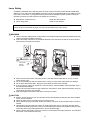
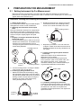
2.1 Setting Instrument Up For Measurement
Mount the instrument to the tripod. Level and center the instrument precisely to insure the best
performance. Use tripods with a tripod screw of 5/8 in. diameter and 11 threads per inch, such as the
Type E wide- frame wooden tripod.
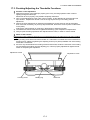
Reference: Leveling and Centering the Instrument
1. Setting up the Tripod
First, extend the extension legs to suitable lengths
and tighten the screws on their midsections.
2. Attaching the Instrument on the Tripod
Head
Place the instrument carefully on the tripod head
and slide the instrument by loosening the tripod
screw. If the plumb bob is positioned right over the
center of the point, slightly tighten the tripod
screw.
3. Roughly Leveling the Instrument by Using
the Circular Level
1 Turn the leveling screws A and B to move the
bubble in the circular level. The bubble is now
located on a line perpendicular to a line
running through the centers of the two leveling
screws being adjusted.
Leveling screw C
Leveling
screw A
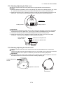
2
Rotate the instrument 90° (100gon) around its
vertical axis and turn the remaining leveling
screw or C to center the bubble once more.
Leveling screw C
90
3
Repeat the procedures 1 and 2 for each 90°
(100gon) rotation of the instrument and check
whether the bubble is correctly centered for all
four points.
5. Centering by Using the Optical Plummet
Telescope
Adjust the eyepiece of the optical plummet
telescope to your eyesight.
Slide the instrument by loosening the tripod
screw, place the point on the center mark, and
then tighten the tripod screw. Sliding the
instrument carefully not to rotate that allows you
to get the least dislocation of the bubble.
Leveling screw B
Point
2
Turn the leveling screw C to bring the bubble
to the center of the circular level.
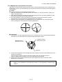
4. Centering by Using the Plate Level
1 Rotate the instrument horizontally by using
the Horizontal motion/clamp screw and place
the plate level parallel with the line connecting
leveling screws A and B, and then bring the
bubble to the center of the plate level by
turning leveling screws A and B.
Center mark
6. Completely Leveling the Instrument
Leveling the instrument precisely in a similar way
to 4. Rotate the instrument and check to see that
the bubble is in the center of the plate level
regardless of telescope direction, then tighten the
tripod screw hard.
Leveling
screw A
Leveling
screw B
2-1
2 PREPARATION FOR MEASUREMENT
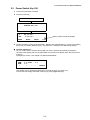
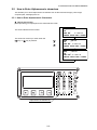
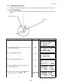
2.2 Power Switch Key ON
1 Confirm the instrument is leveled.
2 Press the power key.
Press the power key
CYGNUS KS-100
V :
HR:
0SET
90°10'20"
0°00'00"
HOLD
Battery Power Remaining Display
HSET
P1↓
z Confirm the battery power remaining display. Replace with charged battery or charge when battery
level is low or indicates “Battery empty”. see Section 2.3 “Battery Power Remaining Display”.
z Contrast adjustment
You can confirm prism constant value (PSM), non-prism constant value (NPM), atmospheric
correction value (PPM) and you can also adjust the contrast of the display when the instrument is
turned on.
To display this screen, see Chapter 16 “SELECTING MODE”.
CONTRAST ADJUSTMENT
PSM: 0.0 PPM
0.0
NPM: 0.0
↓
↑
- - ENTER
This enables you to adjust the brightness by pressing the [F1](↓) or [F2](↑) key.
To memorize the setting value after powering off, press [F4](ENTER) key.
2-2
2 PREPARATION FOR MEASUREMENT
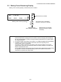
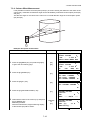
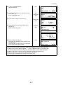
2.3 Battery Power Remaining Display
Battery power remaining display indicates the power condition.
V :
HR:
0SET
90°10'20"
0°00'00"
HOLD
Measurement is possible.
HSET
P1↓
The power is poor. The battery
should be recharged or replaced.
Battery power remaining display
Blinking
<Battery empty>
Other displays disappear.
Note: 1
2
3
Measurement is impossible.
Need to recharge or replace
the battery.
The battery operating time will vary depending on the environmental conditions such as
ambient temperature, charging time, the number of times of charging and discharging
etc. It is recommended for safety to charge the battery beforehand or to prepare spare
full charged batteries.
For general usage of the battery, see Chapter 14 “POWER SOURCE AND CHARGING”.
The battery power remaining display shows the power level regarding to the
measurement mode now operating.
The safety condition indicated by the battery power remaining display in the angle
measurement mode does not necessarily assure the battery’s ability to be used in the
distance measurement mode.
It may happen that the mode change from the angle mode to the distance mode will stop
the operation because of insufficient battery power for the distance mode which
consumes more power than angle mode.
2-3
2 PREPARATION FOR MEASUREMENT
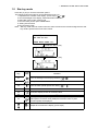
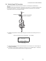
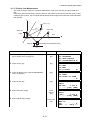
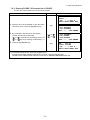
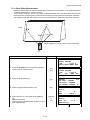
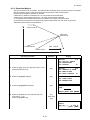
2.4 Vertical Angle Tilt Correction
When the tilt sensors are activated, automatic correction of vertical angle for mislevelment is
displayed.
To ensure a precise angle measurement, tilt sensors must be turned on. The display can also be used
to fine level the instrument. If the (TILT OVER) display appears the instrument is out of automatic
compensation range and must be leveled manually.
Zenith
Standing axis
Inclination of the standing
axis in the X direction
z CYGNUS compensates the vertical angle reading due to inclination of the standing axis in the X
directions .
When the instrument is out of compensation. (TILT OVER)
V :
HR:
° ' "
0°00'00"
<X TILT OVER>
Standing Axis in the X direction
out of range
z To set auto tilt correction from the moment that power is on, see Section 6.4.3 “Vertical Angle Tilt
correction (Tilt ON/OFF)”.
z The display of Vertical angle is unstable when instrument is on an unstable stage or a windy day.
You can turn off the auto tilt correction function of V angle in this case.
2-4
2 PREPARATION FOR MEASUREMENT
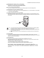
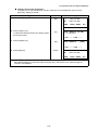
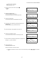
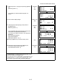
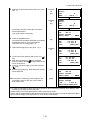
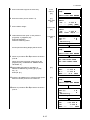
z Setting Tilt Correction by Soft Key
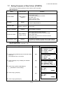
To enable you to select tilt ON/OFF function. setting is not memorized after power is OFF.
[Example] Setting X Tilt OFF
Operating procedure
Option
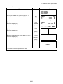
1 Press [F4] key to get the function page 2.
[F4]
Display
V :
HR:
90°10'20"
120°30'40"
0SET
HOLD HSET
TILT
2 Press [F1](TILT) key.
In case ON is already selected, the display shows
tilt correction value.
[F1]
REP
V%
P1↓
P2↓
TILT SENSOR:[X-ON]
X:-0°00'25"
X-ON --- OFF ---
3 Press [F3](OFF) key.
[F3]
TILT SENSOR:
[OFF]
X-ON --- OFF --4 Press [ESC] key.
[ESC]
V :
HR:
90°10'20"
120°30'40"
0SET
HOLD HSET
P1↓
z The setting mode performed here will not be memorized after powering OFF. To set TILT correction in
the initialized setting (it is memorized after powering OFF), see Section 6.4.3 “Vertical Angle Tilt
correction (Tilt ON/OFF)”.
2-5
2 PREPARATION FOR MEASUREMENT
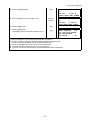
2.5 How to Enter Alphanumeric characters
This enables you to enter alphanumeric characters such as the instrument height, prism height,
occupied point, backsight point etc.
2.5.1 How to Enter Alphanumeric Characters
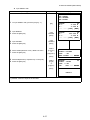
z How to select a item
[Example setting] Occupied point in the data collection mode.
PT#
→ST-01
ID
:
INS.HT:
0.000 m
INPUT SRCH REC OCNEZ
The arrow indicates a item to enter.
The arrow line moves up or down when the
[ ] key or [ ] key is pressed.
[
]
or
[
]
PT#
:ST-01
ID
→
INS.HT: 0.000 m
INPUT SRCH REC OCNEZ
PT#
:ST-01
ID
:
INS.HT→ 0.000 m
INPUT SRCH REC OCNEZ
Alphanumeric characters key
2-6
2 PREPARATION FOR MEASUREMENT
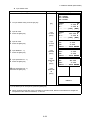
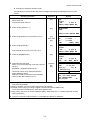
z How to enter characters
[Example setting] HILL-1
1 Move the arrow to enter a item using the [
or [
]
PT#
→
ID
:
INS.HT: 0.000 m
INPUT SRCH REC OCNEZ
] key.
2 Press the [F1] (INPUT) key.
The arrow changes to the equal (=) .
The instrument switches to numerical input mode.
3 Press the [F1] [ALP] key.
The instrument switches to alphabetical input mode.
4 Enter letters of the alphabet by pressing the alphanumeric
characters key.
Example: [9] (GHI) key is pressed three times.
5 Enter other letters of the alphabet in the same way.
6 Press the [F1] (NUM) key, again.
The instrument switches back to numerical input mode.
7 Enter numbers by pressing the alphanumeric characters key.
Example: [ - ], [1] key is pressed.
PT#
=
ID
:
INS.HT: 0.000 m
[ALP][SPC][CLR][ENT]
PT#
=
ID
:
INS.HT: 0.000 m
[NUM][SPC][CLR][ENT]
PT#
=H
ID
:
INS.HT: 0.000 m
[NUM][SPC][CLR][ENT]
PT#
=HILL
ID
:
INS.HT: 0.000 m
[NUM][SPC][CLR][ENT]
PT#
=HILL
ID
:
INS.HT: 0.000 m
[ALP][SPC][CLR][ENT]
PT#
=HILL-1
ID
:
INS.HT: 0.000 m
[ALP][SPC][CLR][ENT]
8 Press [F4](ENT) key.
The arrow moves to next item.
Select next character in the same manner.
z To correct a character, move the cursor to correct character by pressing [
again.
2-7
] or [
] key and enter
3 ANGLE MEASUREMENT
3
ANGLE MEASUREMENT
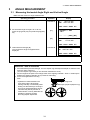
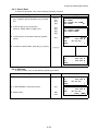
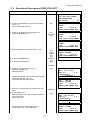
3.1 Measuring Horizontal Angle Right and Vertical Angle
Make sure the mode is in Angle measurement.
Operating procedure
Operation
1 Collimate the 1st target (A).
Display
V : 90°10'20"
HR: 120°30'40"
Collimate A
0SET HOLD HSET P1↓
2 Set horizontal angle of target A at 0° 00' 00".
H ANGLE 0 SET
> OK?
[F1]
Press the [F1](0 set) key and press the [F3](YES)
key.
--- --- [YES][NO]
[F3]
V :
HR:
90°10'20"
0°00'00"
0SET HOLD HSET P1↓
3 Collimate the 2nd target (B).
V : 98°36'20"
HR: 160°40'20"
Collimate B
The required V/H angle to target B will be
displayed.
0SET HOLD HSET P1↓
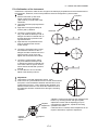
Reference : How to Collimate
1
2
3
Point the telescope toward the light. Turn the diopter ring and adjust the diopter so that the cross
hairs are clearly observed.
(Turn the diopter ring toward you first and then backward to focus.)
Aim the target at the peak of the triangle mark of the sighting collimator. Allow a certain space
between the sighting collimator and yourself for collimating.
Focus the target with the focusing
knob.
* If parallax is created between the
cross hairs and the target when
viewing vertically or horizontally while
looking into the telescope, focusing is
incorrect or diopter adjustment is poor.
This adversely affects precision in
measurement or survey Eliminate the
parallax by carefully focusing
and using diopter adjustment.
Focusing knob
Telescope eyepiece (Diopter ring)
∞
∞
∞
3-1
∞
3 ANGLE MEASUREMENT
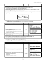
3.2 Switching Horizontal Angle Right/Left
Make sure the mode is Angle measurement.
Operating procedure
Operation
1 Press the [F4](↓) key twice to get the function
[F4]
twice
on page 3.
Display
V : 90°10'20"
HR: 120°30'40"
0SET
2 Press the [F2](R/L) key.
[F2]
The mode Horizontal angle Right (HR)
switches to (HL) mode.
HOLD HSET
P1↓
TILT
REP
V%
P2↓
H-BZ
R/L CMPS
P3↓
V : 90°10'20"
HL: 239°29'20"
H-BZ
R/L CMPS
P3↓
3 Measure as HL mode.
z Every time pressing the [F2](R/L) key, HR/HL mode switches.
3.3 Measuring from the Required Horizontal Angle
3.3.1 Setting by Holding the Angle
Make sure the mode is angle measurement.
Operating procedure
Operation
1 Set the required horizontal angle, using
Display angle
Horizontal tangent screw
Display
V : 90°10'20"
HR: 130°40'20"
0SET HOLD HSET P1↓
2 Press the [F2](HOLD) key.
[F2]
3 Collimate the target.
H ANGLE HOLD
HR: 130°40'20"
> SET ?
--- --- [YES][NO]
Collimate
4 Press the [F3](YES) key to finish holding the
[F3]
horizontal angle.*1)
The display turns back to normal angle
measurement mode.
V : 90°10'20"
HR: 130°40'20"
0SET HOLD HSET P1↓
*1) To return to the previous mode, press the [F4](NO) key.
3-2
3 ANGLE MEASUREMENT
3.3.2 Setting a Horizontal Angle from the Keys
Make sure the mode is Angle measurement.
Operating procedure
Operation
1 Collimate the target.
Collimate
Display
V : 90°10'20"
HR: 170°30'20"
0SET HOLD HSET P1↓
2 Press the [F3](HSET) key.
[F3]
H ANGLE SET
HR=
--- --- [CLR] [ENT]
3 Input the required horizontal angle by
using keys. *1)
70.4020
[F4]
For example :70°40'20"
V :
HR:
90°10'20"
70°40'20"
0SET HOLD HSET P1↓
When completed, normal measuring from the
required Horizontal angle is possible.
*1) To enter Alphanumeric characters, see Section 2.5 “How to Enter Alphanumeric characters”.
3.4 Vertical Angle Percent Grade(%) Mode
Make sure the mode is Angle measurement.
Operating procedure
Operation
1 Press the [F4](↓) key to get the function on page 2.
[F4]
Display
V : 90°10'20"
HR: 170°30'20"
0SET HOLD HSET P1↓
TILT
2 Press the [F3](V%) key. *1)
[F3]
REP
V%
P2↓
V : -0.30
%
HR: 170°30'20"
TILT
REP
V%
P2↓
*1) Every time pressing the [F3](V%) key, the display mode switches.
z When the measurement is carried out over ±45° (±100%) from the horizontal, the display shows
<OVER>.
3-3
3 ANGLE MEASUREMENT
3.5 Repetition Angle Measurement
z Repetition angle measurement can be done by horizontal angle right measurement mode.
Make sure the mode is Horizontal Angle Right measurement.
Operating procedure
Operation
1 Press the [F4](↓) key to get the function on page 2.
[F4]
Display
V : 90°10'20"
HR: 170°30'20"
0SET HOLD HSET P1↓
TILT
2 Press the [F2](REP)key.
[F2]
[F3]
4 Collimate the target A and press the [F1] (0SET)
key.
5 Press the [F3] (YES) key.
6 Collimate the target B using the horizontal clamp
and tangent screw.
Press the [F4](HOLD) key.
7 Recollimate target A using the horizontal clamp
and tangent screw, and press the [F3](REL)key.
8 Recollimate target B using the horizontal clamp
and tangent screw, and press the [F4](HOLD) key.
9 Repeat 7 to 8 to measure the desired number of
repetitions.
Collimate A
[F1]
V%
P2↓
REPETITION ANGLE
> OK?
---
3 Press the [F3](YES) key.
REP
---
[YES][NO]
REP-ANGLE COUNT[ 0]
Ht:
0°00'00"
Hm:
0SET V/H REL HOLD
REPETITION ANGLE
INITIALIZE
> OK?
--- --- [YES][NO]
[F3]
REP-ANGLE COUNT[ 0]
Ht:
0°00'00"
Hm:
0SET V/H REL HOLD
Collimate B
[F4]
REP-ANGLE COUNT[ 1]
Ht:
45°10'00"
Hm:
45°10'00"
0SET V/H REL HOLD
Collimate A
[F3]
REP-ANGLE COUNT[ 1]
Ht:
45°10'00"
Hm:
45°10'00"
0SET V/H REL HOLD
Collimate B
[F4]
REP-ANGLE COUNT[ 2]
Ht:
90°20'00"
Hm:
45°10'00"
0SET V/H REL HOLD
REP-ANGLE COUNT[ 4]
Ht: 180°40'00"
Hm:
45°10'00"
0SET V/H REL HOLD
[Example] 4 measurement
3-4
3 ANGLE MEASUREMENT
10 To return to the normal angle mode, press the
[ESC]
or
[F2]
[F2](V/H) key or [ESC] key.
11 Press the [F3](YES) key.
[F3]
REPETITION ANGLE
Exit
> OK?
--- --- [YES][NO]
V : 90°10'20"
HR: 170°30'20"
0SET HOLD HSET P1↓
z Horizontal angle can be accumulated up to
(3600°00'00" – minimum reading) (horizontal angle right).
In case of 5 second reading, horizontal angle can be accumulated up to +3599°59'55".
z Error will be displayed when the results differ from first measurement by more than ±30".
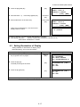
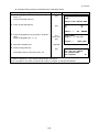
3.6 Buzzer Sounding for Horizontal Angle 90° Increments
When the horizontal angle falls in the range of less than ± 1° of 0°, 90°, 180° or 270°, the buzzer
sounds. Buzzer stops only when the horizontal angle is adjusted to 0°00’00”, 90°00’00” , 180°00’00” or
270°00’00”.
This setting is not memorized after powering off. Refer to 16 “SELECTING MODE” to set the initial
setting (memorized after powering off).
Make sure the mode is Angle measurement.
Operating procedure
Operation
1 Press the [F4](↓) key twice to get the function
[F4]
twice
on page 3.
2 Press the [F1](H-BZ) key.
[F1]
The data previously set is shown.
Display
V : 90°10'20"
HR: 170°30'20"
0SET
HOLD
H-BZ
R/L
HSET P1↓
CMPS
P3↓
H-ANGLE BUZZER [OFF]
[ON] [OFF] --- ENTER
3 Press the [F1](ON) key or [F2](OFF) key to select
the buzzer ON/OFF.
[F1] or [F2]
H-ANGLE BUZZER [ON]
[ON] [OFF] --- ENTER
4 Press the [F4](ENTER) key.
[F4]
V : 90°10'20"
HR: 170°30'20"
0SET HOLD HSET P1↓
3-5
3 ANGLE MEASUREMENT
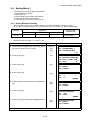
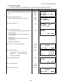
3.7 Compasses (vertical angle)
Vertical angle is displayed as shown below.
+90°
0°
0°
-90°
Operating procedure
Operation
1 Press the [F4](↓) key twice to get the function
[F4]
twice
on page 3.
Display
V : 98°10'20"
HR: 170°30'20"
0SET HOLD HSET P1↓
H-BZ R/L
2 Press the [F3](CMPS) key. *1)
[F3]
V : - 8°10'20"
HR: 170°30'20"
H-BZ R/L
*1) Every time pressing the [F3](CMPS) key, the display mode switches.
3-6
CMPS P3↓
CMPS P3↓
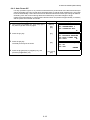
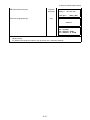
4 DISTANCE MEASUREMENT
4
DISTANCE MEASUREMENT
z Prism mode and Non-prism mode
You can select measurement mode between Prism mode which collimating a prism and Non-prism
mode that is collimating a target object except prism.
z When using a reflection sheet, measure with the prism mode.
z For measurement with a prism, be sure to measure with the prism mode. If you measure with the
non-prism mode, accuracy cannot be guaranteed.
z Non-prism mode enables all distance measurements such Distance measurement, Coordinate
measurement, Offset measurement and Layout.
z To switch over Prism mode to Non-prism mode or contrary, press the [NP/P] soft key in each
measurement display. [NP] of Non-prism mode indicator will be shown at the right corner of the
display in Non-prism mode measurement.
Changing mode shall be done before measurement.
Example
Distance measurement mode
HR: 120°30'40"
N
HD*
65.432 m
P
VD:
12.345 m
MEAS MODE NP/P P1↓
Coordinate measurement mode
Non-prism
mode
indicator
N: 120.456 m
E:
34.567 m
Z:
12.345 m
MEAS MODE NP/P
N
P
P1↓
To change the mode, press the [NP/P] soft key in each measurement.
z It is possible to set Non-prism mode for distance measurement during the power on time. Refer to
16.SELECTING MODE to set the option.
z If happened collimating the near distance prism in Non-prism mode, measurement will not be done
because of too much light.
4.1 Setting of the Atmospheric Correction
When setting the atmospheric correction, obtain the correction value by measuring the temperature
and pressure. Refer to Section 12.2 “Setting of Atmospheric Correction Value”.
4.2 Setting of the Correction for Prism Constant / Non-prism Constant
Topcon’s prism constant value is 0. Set correction for prism at 0. If the prism is of another manufacture,
the appropriate constant shall be set beforehand. Refer to Chapter 11 “SETTING THE PRISM / NONPRISM CONSTANT VALUE”. The setting value is kept in the memory even after power is off.
Note: Confirm that Non-prism correction value is set at zero before measurement target such
as a wall in Non-prism mode.
4-1
4 DISTANCE MEASUREMENT
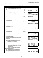
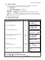
4.3 Distance Measurement (Continuous Measurement)
Make sure the mode displays angle measurement.
Operating procedure
Operation
1 Collimate the center of prism.
Collimate P
Display
V : 90°10'20"
HR: 120°30'40"
0SET HOLD HSET P1↓
2 Press the [
] key.
Distance measurement starts. *1),2)
[
]
The measured distances are shown. *3)~*5)
HR: 120°30'40"
HD*[r]
<< m
VD:
m
MEAS MODE NP/P P1↓
HR: 120°30'40"
HD*
123.456 m
VD:
5.678 m
MEAS MODE NP/P P1↓
z Pressing the [
] key again, the display
changes to horizontal (HR) and vertical (V)angle
and slope distance(SD). *6)
*
[
]
V : 90°10'20"
HR: 120°30'40"
SD*
131.678 m
MEAS MODE NP/P P1↓
*1) When EDM is working, the " " mark appears in the display.
*2) To change mode from Fine to Coarse or Tracking, refer to section 4.5 “Fine Mode/Tracking Mode/
Coarse Mode”.
To set the distance measurement on when the instrument is powered on, refer to Chapter 16
“SELECTING MODE”.
*3) The distance unit indicator "m" (for meter) , "f" (for feet or feet inch) appears and disappears
alternatively with buzzer sounds at every renewal of distance data.
*4) Measurement may repeat automatically in the instrument if the result is affected by shimmer etc.
*5) To return to the normal measuring angle mode from a distance measuring mode, press the [ANG] key.
*6) It is possible to choose the display order (HR, HD, VD) or (V, HR, SD) for initial measuring distance
mode. Refer to Chapter 16 “SELECTING MODE”.
4-2
4 DISTANCE MEASUREMENT
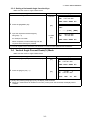
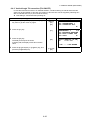
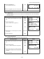
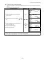
4.4 Distance Measurement (N-time Measurement/Single Measurement)
When the number of times measurement is preset, the CYGNUS measures the distance the set
number of times. The average distance will be displayed.
When presetting the number of times as 1, it does not display the average distance, because of single
measurement. Single measurement is set at the factory.
Make sure the mode displays angle measurement.
Operating procedure
Operation
1 Collimate the center of prism.
Display
V :
HR:
90°10'20"
120°30'40"
0SET HOLD HSET
P1↓
2 Press the [
[
]
HR: 120°30'40"
HD*[r]
<< m
VD:
m
MEAS MODE NP/P P1↓
3 Press [F1](MEAS) key while continuous
[F1]
HR: 120°30'40"
HD*[n]
<< m
VD:
m
MEAS MODE NP/P P1↓
] key.
Continuous measuring starts.*1)
measuring is exceeding. *2)
The average value is displayed and "*" mark
disappears.
z While EDM is working, press [F1](MEAS) key
again, the mode will be changed to continuous
measuring mode.
HR: 120°30'40"
HD:
123.456 m
VD:
5.678 m
MEAS MODE NP/P P1↓
*1) It is possible to set the measurement mode for N-times measurement mode or continuous
measurement mode when the power is turned on. Refer to Chapter 16 “SELECTING MODE”.
*2) For setting the number of times (N-times) in the measurement, refer to Chapter 16 “SELECTING
MODE”.
4-3
4 DISTANCE MEASUREMENT
z Choose meter /feet / feet+inch unit by soft key
It is possible to change the unit for distance measurement mode by soft key.
This setting is not memorized after power off. Refer to 16 “SELECTING MODE” to set at the initial
setting (memorized after power off).
Operating procedure
Operation
1 Press the [F4](P1↓) key twice to get the function
on page 3.
2 Press the [F2](m/f/i) key, the display unit will be
[F4]
[F2]
changed.
z Every time pressing the [F2](m/f/i) key, the unit
mode switches.
Display
HR: 120°30'40"
HD*
2.000 m
VD:
3.000 m
MEAS MODE NP/P
P1↓
OFSET S.O
S/A
P2↓
--- m/f/i ---
P3↓
HR: 120°30'40"
HD*
6.560 f
VD:
9.845 f
--- m/f/i ---
P3↓
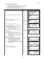
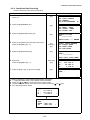
4.5 Fine Mode/Tracking Mode/Coarse Mode
This setting is not memorized after power is off. Refer to Chapter 16 “SELECTING MODE” to set at the
initial setting (memorized after power is off).
•Fine Mode
: This is a normal distance measuring mode.
The unit to be displayed can be changed.
Measurement time will vary depending on the unit to be displayed.
•Tracking Mode : This mode measures in shorter time than in fine mode.
It is very useful when tailing the moving object or carrying out stake-out work.
•Coarse Mode
: This mode measures in shorter time than in fine mode.
The unit to be displayed can be changed.
To change the unit to be displayed in fine mode, see Chapter 16 “SELECTING MODE” and to change
the unit in course mode, see section 6.4.1 “Setting Minimum Reading”.
For the details of the unit and measurement time in each mode, see Chapter 23 “SPECIFICATIONS”.
Operating procedure
Operation
Display
HR: 120°30'40"
HD*
123.456m
VD:
5.678m
MEAS MODE NP/P
1 Press the [F2](MODE) key from the distance
[F2]
measuring mode.*1)
The initial character (F/T/C) of set mode is
displayed . (F:Fine, T:Tracking, C:Coarse)
2 Press the [F1](FINE) key, [F2](TRACK) key, or
[F1]~[F3]
[F3](COARSE) key.
*1) To cancel the setting, press the [ESC] key.
4-4
P1↓
HR: 120°30'40"
HD*
123.456m
VD:
5.678m
FINE TRACK COARSE F
HR: 120°30'40"
HD*
123.456m
VD:
5.678m
MEAS MODE NP/P
P1↓
4 DISTANCE MEASUREMENT
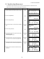
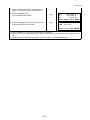
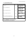
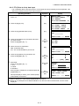
4.6 Stake Out (S.O)
The difference between the measured distance and the input stake out distance is displayed.
Measured distance — Stake out distance = Displayed value
z In stake out operation, you can select either horizontal distance (HD), relative elevation (VD) and
slope distance (SD)
Operating procedure
1 Press the [F4](↓) key in the distance measuring
mode to get the function on page 2.
Operation
Display
[F4]
HR: 120°30'40"
HD*
123.456 m
VD:
5.678 m
MEAS MODE NP/P P1↓
OFSET S.O
2 Press the [F2](S.O) key.
[F2]
The data previously set is shown.
[F3] key.
[F1]
Example : Horizontal distance
P2↓
STAKE OUT
HD :
0.000 m
HD
3 Select the measuring mode by pressing the [F1] to
S/A
VD
SD
---
STAKE OUT
HD =
0.000 m
--- --- [CLR] [ENT]
4 Enter the distance for stake out. *1)
Enter data
[F4]
STAKE OUT
HD :
100.000 m
INPUT --- --- ENTER
5 Collimate the target (Prism).
Collimate P
Measuring starts.
The difference between the measured distance
and the stake out distance is displayed.
6 Move the target until the difference becomes 0m.
HR: 120°30'40"
dHD*[r]
<< m
VD:
m
MEAS MODE NP/P P1↓
HR: 120°30'40"
dHD*
23.456 m
VD:
5.678 m
MEAS MODE NP/P P1↓
*1) Refer to section 2.5 “How to Enter Alphanumeric characters”.
z To return to normal distance measurement mode, stake out distance to "0" or turn the power off.
4-5
4 DISTANCE MEASUREMENT
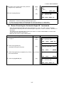
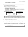
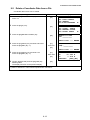
4.7 Offset Measurement
There are four offset measurement modes in the Offset Measurement.
z Angle offset
z Distance offset
z Plane offset
z Column offset
To show the offset measurement menu, press the [OFSET] soft key from distance or coordinate
measurement mode.
Example:
Coordinate measurement
Distance measurement
N:
E:
Z:
MEAS
HR: 120°30'40"
HD:
123.456 m
VD:
5.678 m
MEAS MODE NP/P P1↓
OFSET S.O
S/A
123.456
34.567
78.912
MODE NP/P
R.HT INSHT
P2↓
m
m
m
P1↓
OCC
P2↓
OFSET m/f/i S/A
P3↓
Press the [F1](OFSET) key.
Press the [F1](OFSET) key.
Offset Measurement Menu
OFFSET
1/2
F1:ANG.OFFSET
F2:DIST.OFFSET
F3:PLANE OFFSET P↓
[F4]
OFFSET
2/2
F1:COLUMN OFFSET
P↓
z Outputting the Measurement Data
The results of offset measurement can be output to external device.
Setting the function of the [ESC] key to (REC), the [F3] soft key which assigned (REC) will appear in
measured result display.
Refer to Chapter 16 “SELECTING MODE” to set this option.
OFFSET-MEASUREMENT
HR: 120°30'40"
SD:
123.456 m
NEXT --- REC --[F3]
z Distance measurement mode of the offset measurement
Offset measurement will be done by N-time fine measurement mode.
For setting measuring times refer to Chapter 16 “SELECTING MODE”.
4-6
4 DISTANCE MEASUREMENT
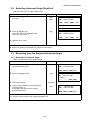
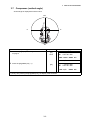
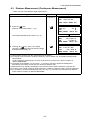
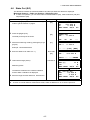
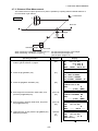
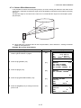
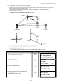
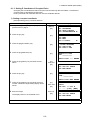
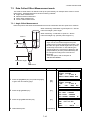
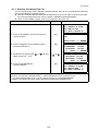
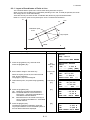
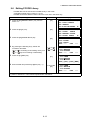
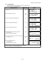
4.7.1 Angle Offset
This mode is useful when it is difficult to set up the prism directly, for example at the center of a tree.
Place the prism at the same horizontal distance from the instrument as that of point A0 to measure.
To measure the coordinates of the center position, operate the offset measurement after setting the
instrument height/prism height.
When measuring coordinates of ground point A1
:Set the instrument height/prism height.
When measuring coordinates of point A0 : Set
the instrument height only. (Set the prism height
to 0 ).
Prism P
Prism height
When sighting to A0, you can select one of two
ways. One is to fix vertical angle to the prism
position even updown the telescope position, and
the other is to gear vertical angle to the updown of
telescope movement. In case following the
vertical angle to the movement of telescope,
SD(Slope Distance) and VD(Vertical Distance)
will be changed according to the movement of
telescope.
To set this option, refer to Chapter 16
“SELECTING MODE”.
Instrument height
Occ. Point
z Set the instrument height/prism height before proceeding to the offset measurement mode.
z When setting the coordinate value for the occupied station, refer to Section 5.1 “Setting Coordinate
Values of Occupied Point”.
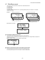
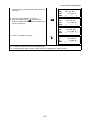
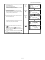
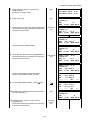
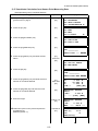
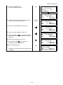
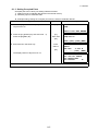
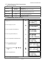
Operating procedure
Operation
Display
1 Press the [F4](P1↓) key from distance measuring
[F4]
HR: 120°30'40"
HD:
123.456 m
VD:
5.678 m
MEAS MODE NP/P P1↓
OFSET S.O S/A P2↓
2 Press the [F1](OFSET) key.
[F1]
OFFSET
1/2
F1:ANG.OFFSET
F2:DIST.OFFSET
F3:PLANE OFFSET P1↓
3 Press the [F1](ANG. OFFSET) key.
[F1]
OFFSET-MEASUREMENT
HR: 120°30'40"
HD:
m
MEAS --- NP/P ---
mode to get the function on page 2.
4 Collimate prism P, and press the [F1](MEAS) key.
4-7
Collimate P
[F1]
OFFSET-MEASUREMENT
HR: 110°20'30"
HD* [n]
<< m
>Measuring...
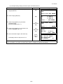
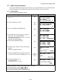
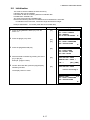
4 DISTANCE MEASUREMENT
The horizontal distance from the instrument to the
prism will be measured.
5 Collimate point A0 using the horizontal motion
OFFSET-MEASUREMENT
HR:
110°20'30"
HD:
56.789 m
NEXT --- --- --Collimate
A0
clamp and horizontal tangent screw.
OFFSET-MEASUREMENT
HR:
113°30'50"
HD:
56.789 m
NEXT --- --- ---
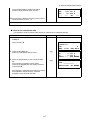
6 Show the relative elevation of point A0.
[
]
OFFSET-MEASUREMENT
HR:
113°20'30"
VD:
3.456 m
NEXT --- --- ---
7 Show the slope distance of point A0.
[
]
OFFSET-MEASUREMENT
HR:
113°20'30"
SD:
56.894 m
NEXT --- --- ---
[
]
OFFSET-MEASUREMENT
HR:
113°20'30"
N :
-12.345 m
NEXT --- --- ---
z Each time pressing the [
] key, horizontal
distance, relative elevation and slope distance are
shown in sequence.
8 Show N coordinate of point A0 or A1.
z Each time pressing [
] key, N,E and Z
coordinate are shown in sequence.
z To return to procedure 4, press the [F1](NEXT) key.
z To return to the previous mode, press the [ESC] key.
z To select the Non-prism or Prism mode, press the [F3](NP/P) key after the step 3.
4-8
4 DISTANCE MEASUREMENT
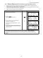
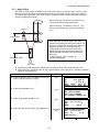
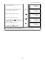
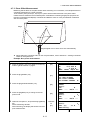
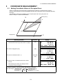
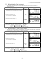
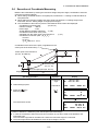
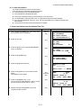
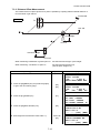
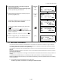
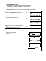
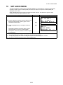
4.7.2 Distance Offset Measurement
The measurement of a place apart from a prism is possible by inputting offset horizontal distance of
front and back / right and left.
Forward HD
oHD sign
A0
RorL HD
A1
Prism height
Prism P
Instrument height
Occ.Point
When measuring coordinates of ground point A1:
When measuring coordinates of point A0:
Set the instrument height / prism height.
Set the instrument height only.
(Set the prism height to 0 ).
Operating procedure
Operation
Display
1 Press the [F4](P1↓) key from distance measuring
[F4]
HR: 120°30'40"
HD:
123.456 m
VD:
5.678 m
MEAS MODE NP/P P1↓
OFSET S.O
S/A P2↓
2 Press the [F1](OFSET) key.
[F1]
OFFSET
1/2
F1:ANG.OFFSET
F2:DIST.OFFSET
F3:PLANE OFFSET P↓
3 Press the [F2](DIST. OFFSET) key.
[F2]
DISTANCE OFFSET
INPUT RorL HD
oHD=
m
--- --- [CLR] [ENT]
Enter HD
[F4]
DISTANCE OFFSET
INPUT FORWARD HD
oHD=
m
--- --- [CLR] [ENT]
Enter HD
[F4]
DISTANCE OFFSET
HR: 80°30'40"
HD:
m
MEAS --- NP/P ---
Collimate
P1
[F1]
DISTANCE OFFSET
HR: 80°30'40"
HD* [n]
<< m
>Measuring...
mode to get the function on page 2.
4 Enter Right and Left direction offset value, and
press the [F4](ENTER) key.
5 Enter Forward direction offset value, and press
the [F4](ENTER) key.
6 Collimate prism P, and press the [F1](MEAS) key.
Measuring will start.
4-9
4 DISTANCE MEASUREMENT
After measuring, the result added offset value will
be shown.
7 Show the relative elevation of point P0.
z Each time pressing the [
] key, horizontal
distance, relative elevation and slope distance are
shown in sequence.
DISTANCE OFFSET
HR:
80°30'40"
HD*
10.000 m
NEXT --- --- --[
]
DISTANCE OFFSET
HR:
80°30'40"
VD:
11.789 m
NEXT --- --- --DISTANCE OFFSET
HR:
80°30'40"
SD:
11.789 m
NEXT --- --- ---
z Show coordinate of point P0.
[
]
N :
E :
Z :
NEXT
12.345
23.345
1.345
--- ---
z To return to procedure 4, press [F1](NEXT) key.
z To return to the previous mode, press [ESC] key.
z To select the Non-prism or Prism mode, press the [F3](NP/P) key after the step 4.
4-10
m
m
m
---
4 DISTANCE MEASUREMENT
4.7.3 Plane Offset Measurement
Measuring will be taken for the place where direct measuring can not be done, for example distance or
coordinate measuring for a edge of a plane.
Three random prism points (P1, P2, P3) on a plane will be measured at first in the plane offset
measurement to determine the measured plane. Collimate the measuring target point (P0) then the
instrument calculates and displays coordinate and distance value of cross point between collimation
axis and of the plane.
P
Edge
P
P2
P3
Target heights of P1 to P3 is set to zero automatically.
z When setting the coordinate value for the occupied station, refer to Section 5.1 “Setting Coordinate
Values of Occupied Point”.
Example: Non-prism measurement
Operating procedure
Operation
Display
1 Press the [F4](P1↓) key from distance measuring
[F4]
HR: 120°30'40"
HD:
123.456 m
VD:
5.678 m
MEAS MODE NP/P P1↓
OFSET S.O
S/A P2↓
2 Press the [F1](OFSET) key.
[F1]
OFFSET
1/2
F1:ANG.OFFSET
F2:DIST.OFFSET
F3:PLANE OFFSET P↓
3 Press the [F3](PLANE OFFSET) key.
[F3]
PLANE
N001#:
SD:
MEAS ---
mode to get the function on page 2.
4 Press the [F3](NP/P) key to change to the non-
[F3]
prism mode.
5 Collimate first point P1, and press the [F1](MEAS)
key.
N-time measuring will start.
After measuring, the display will show the second
point measurement.
4-11
Collimate
P1
[F1]
PLANE
N001#:
SD:
MEAS ---
m
NP/P --N
m
P
NP/P ---
PLANE
N001#:
SD* [n]
<< m
>Measuring...
N
P
4 DISTANCE MEASUREMENT
6 Measure the second and third points in the same
way.
Collimate
P2
[F1]
Collimate
P3
[F1]
The instrument calculates and displays coordinate
and distance value of cross point between
collimation axis and of the plane. *1), 2)
7 Collimate the edge (P0) of the plane. *3), 4)
8 To show the slope distance (SD), press the [
Collimate
P0
]
key.
z Each time pressing the [
] key, horizontal
distance, relative elevation and slope distance are
shown in sequence.
z To show coordinate of point P0, press the [
]
key.
PLANE
N002#:
SD:
MEAS --PLANE
N003#:
SD:
MEAS ---
N
m
P
NP/P ---
N
m
P
NP/P ---
HR:
HD:
VD:
EXIT
80°30'40"
54.321 m NP
10.000 m
HR:
HD:
VD:
EXIT
75°30'40"
54.600 m NP
-0.487 m
V :
HR:
SD:
EXIT
90°30'40"
75°30'40" NP
56.602 m
9 To escape the measuring, press the [F1](EXIT)
key. The display returns to the previous mode.
*1) In case the calculation of plane was not successful by the measured three points, error displays. Start
measuring over again from the first point.
*2) Data display is the mode beforehand of offset measurement mode.
*3) Error will be displayed when collimated to the direction which does not cross with the determined plane.
*4) The point height of the target point P0 is set to zero automatically.
4-12
4 DISTANCE MEASUREMENT
4.7.4 Column Offset Measurement
If it is possible to measure circumscription point (P1) of column directly, the distance to the center of the
column (P0), coordinate and direction angle can be calculated by measured circumscription points (P2)
and (P3).
The direction angle of the center of the column is 1/2 of total direction angle of circumscription points
(P2) and (P3).
P
P2
P3
P
z When setting the coordinate value for the occupied station, refer to Section 5.1 “Setting Coordinate
Values of Occupied Point”.
Example: Non-prism measurement
Operating procedure
Operation
Display
1 Press the [F4](P1↓) key from distance measuring
[F4]
HR: 120°30'40"
HD:
123.456 m
VD:
5.678 m
MEAS MODE NP/P P1↓
OFSET S.O
S/A P2↓
2 Press the [F1](OFSET) key.
[F1]
OFFSET
1/2
F1:ANG.OFFSET
F2:DIST.OFFSET
F3:PLANE OFFSET P↓
3 Press the [F4](P↓) key.
[F4]
OFFSET
2/2
F1:COLUMN OFFSET
mode to get the function on page 2.
P↓
4 Press the [F1](COLUMN OFFSET) key.
[F1]
COLUMN OFFSET
Center
HD:
m
MEAS --- NP/P ---
5 Press the [F3](NP/P) key to change to the non-
[F3]
COLUMN OFFSET
N
Center
P
HD:
m
MEAS --- NP/P ---
prism mode.
4-13
4 DISTANCE MEASUREMENT
6 Collimate the center of the column (P1) and press
the [F1](MEAS) key.
N-time measuring will start.
After the measurement, angle measuring display
of the left side (P2) will be shown.
7 Collimate the left side of the column (P2) and
press the [F4](SET) key.
After the measurement, angle measuring display
of the right side (P3) will be shown.
8 Collimate the right side of the column (P3) and
press the [F4](SET) key.
Collimate
P1
[F1]
COLUMN OFFSET
Center
HD* [n]
<< m
>Measuring...
Collimate
P2
[F4]
COLUMN OFFSET
N
Left
P
HR: 120°30'40"
--- --- --- SET
Collimate
P3
[F4]
COLUMN OFFSET
N
Right
P
HR: 180°30'40"
--- --- --- SET
The distance between the instrument and center
of the column (P0) will be calculated.
9 To show the relative elevation (VD), press the
[
] key.
Each time pressing the [
] key, horizontal
distance, relative elevation and slope distance are
shown in sequence.
z To show coordinate of point P0, press the [
]
key.
10 To escape the measuring, press the [ESC] key.
The display returns to the previous mode.
4-14
N
P
COLUMN OFFSET
HR: 150°30'40" NP
HD:
43.321 m
NEXT --- --- --[
]
COLUMN OFFSET
HR: 150°30'40" NP
VD:
2.321 m
NEXT --- --- ---
5 COORDINATE MEASUREMENT
5
COORDINATE MEASUREMENT
5.1 Setting Coordinate Values of Occupied Point
Set the coordinates of the instrument (occupied point) according to coordinate origin, and the
instrument automatically converts and displays the unknown point (prism point) coordinates following
the origin.
It is possible to retain the coordinates of the occupied point after turning the power off.
Refer to Chapter 16 “SELECTING MODE”.
Prism (n,e,z)
N
z
n
Occupied point C
Origin(0,0,0)
E
e
Operating procedure
Operation
1 Press the [F4](↓) key from the coordinate
measurement mode to get the function on page 2.
2 Press the [F3](OCC) key.
3 Enter N coordinate value. *1)
Display
[F4]
N:
123.456
E:
34.567
Z:
78.912
MEAS MODE NP/P
R.HT INSHT OCC
[F3]
N=
0.000 m
E:
0.000 m
Z:
0.000 m
--- --- [CLR] [ENT]
Enter data
[F4]
N:
-72.000 m
E=
0.000 m
Z:
0.000 m
--- --- [CLR] [ENT]
4 Enter E and Z coordinate values in the same
m
m
m
P1↓
P2↓
N:
51.456 m
E:
34.567 m
Z:
78.912 m
MEAS MODE NP/P P1↓
manner.
After entering the values, the display returns
coordinate measuring display.
*1) Refer to Section 2.5 “How to Enter Alphanumeric characters”.
z Input range –99999999.9990 < N,E,Z < +99999999.9990 m
–99999999.999 < N,E,Z < +99999999.999 ft.
–99999999.11.7 < N,E,Z < +99999999.11.7 ft.+inch
5-1
5 COORDINATE MEASUREMENT
5.2 Setting Height of the Instrument
It is possible to retain the height of instrument after turning the power off. Refer to Chapter 16
“SELECTING MODE”.
Operating procedure
Operation
1 Press the [F4](↓) key from the coordinate
measurement mode to get the function on page 2.
2 Press the [F2](INSHT) key.
The current value is displayed.
3 Enter the instrument height. *1)
Display
[F4]
N:
123.456
E:
34.567
Z:
78.912
MEAS MODE NP/P
R.HT INSHT OCC
[F2]
INSTRUMENT HEIGHT
INPUT
INS.HT= 0.000 m
--- --- [CLR] [ENT]
Enter Inst.HT
[F4]
N:
E:
Z:
MEAS
123.456
34.567
78.912
MODE NP/P
m
m
m
P1↓
P2↓
m
m
m
P1↓
*1) Refer to Section 2.5 “How to Enter Alphanumeric characters”.
z Input range –999.9999 < Instrument height < +999.9999 m
–999.999 < Instrument height < +999.999 ft.
–999.11.7 < Instrument height < +999.11.7 ft.+inch
5.3 Setting Height of Target (Prism Height)
This mode can be used to obtain Z coordinate values . It is possible to retain the height of target after
turning the power off. Refer to Chapter 16 “SELECTING MODE”.
Operating procedure
Operation
1 Press the [F4](↓) key from the coordinate
measurement mode to get the function on page 2.
2 Press the [F1](R.HT) key.
The current value is displayed.
3 Enter the prism height. *1)
[F4]
N:
123.456
E:
34.567
Z:
78.912
MEAS MODE NP/P
R.HT INSHT OCC
[F1]
REFLECTOR HEIGHT
INPUT
R.HT= 0.000 m
--- --- [CLR] [ENT]
Enter R. HT
[F4]
*1) Refer to Section 2.5 “How to Enter Alphanumeric characters”.
z Input range –999.9999 < Prism height < +999.9999 m
–999.999 < Prism height < +999.999 ft.
–999.11.7 < Prism height < +999.11.7 ft.+inch
5-2
Display
N:
E:
Z:
MEAS
123.456
34.567
78.912
MODE NP/P
m
m
m
P1↓
P2↓
m
m
m
P1↓
5 COORDINATE MEASUREMENT
5.4 Execution of Coordinate Measuring
Measure the coordinates by entering the instrument height and prism height, coordinates of unknown
point will be measured directly.
z When setting coordinate values of occupied point, see Section 5.1 “Setting Coordinate Values of
Occupied Point”
z When setting the instrument height and prism height, see Section 5.2 “Setting Height of the
Instrument” and 5.3 “Setting Height of Target (Prism Height)”.
z The coordinates of the unknown point are calculated as shown below and displayed:
Coordinates of occupied point
: (N0, E0,Z0)
Instrument height : INS.HT
Prism height
: R.HT
Vertical distance (Relative elevation) : z (VD)
Coordinates of the center of the prism,
originated from the center point of the instrument : (n,e,z)
Coordinates of unknown point : (N1,E1,Z1)
N1=N0+n
E1=E0+e
Z1=Z0+INS.HT+z - R.HT
Coordinates of the center of the prism, originated from the
center point of the instrument (n, e, z)
Center point of the instrument
(No, Eo, Zo+INS.HT)
Unknown point
(N1, E1, Z1)
Occupied point (No, Eo, Zo)
Origin (o, o, o)
Operating procedure
Operation
1 Set the direction angle of known point A. *1)
2 Collimate target prism.
3 Press the [
] key.
Measuring starts.
Display
Set direction
angle
V : 90°10'20"
HR: 120°30'40"
Collimate P
0SET
[
]
HOLD
HSET P1↓
N*[r]
E:
Z:
MEAS MODE
<< m
m
m
NP/P P1↓
N*
E:
Z:
MEAS
The result will be shown.
123.456
34.567
78.912
MODE NP/P
m
m
m
P1↓
*1) Refer to Section 3.3 “Measuring from the Required Horizontal Angle”.
z In case the coordinate of instrument point is not entered, (0,0,0) will be used as the default for the
instrument point.
The instrument height will be calculated as 0 when the instrument height is not entered.
z The prism height will be calculated as 0 when the prism height is not set.
5-3
6 SPECIAL MODE (Menu Mode)
6
SPECIAL MODE (Menu Mode)
By pressing the [MENU] key, the instrument will be in MENU mode.
In this mode, special measuring , setting and adjustment are possible.
Normal measurement mode
[ESC]
[MENU]
MENU
1/3
F1:DATA COLLECT
[ESC]
F2:LAYOUT
F3:MEMORY MGR. P↓
[ESC] [F1]
"DATA COLLECTION MODE"
See Chapter 7 “DATA COLLECTION”.
[F2]
"LAYOUT MODE"
[F4]
See Chapter 8 “LAYOUT”.
[F3]
"MEMORY MANAGER MODE"
See Chapter 9 “MEMORY MANAGER
MODE”.
Programs
MENU
2/3
[ESC] F1:PROGRAMS
F2:GRID FACTOR
F3:ILLUMINATION P↓
[ESC]
[F1]
PROGRAMS
F1:REM
F2:MLM
F3:Z COORD.
1/2
P↓
Grid factor
[F4]
[F2]
GRID FACTOR
=1.000000
>MODIFY? [YES][NO]
Illumination
[F3]
ILLUMINATION[ON:]
F1:ON
F2:OFF
Setting mode 1
[ESC]
MENU
3/3
F1:PARAMETERS 1
F2:CONTRAST ADJ.
P↓
[ESC]
[F1]
[F4]
PARAMETERS 1
1/3
F1:MINIMUM READING
F2:AUTO POWER OFF
F3:TILT
P↓
Display contrast adjustment
[F2]
CONTRAST ADJUSTMENT
LEVEL:4
↓
6-1
↑
--- ENTER
6 SPECIAL MODE (Menu Mode)
6.1 Application Measurement (PROGRAMS)
6.1.1 Remote Elevation measurement (REM)
To obtain elevation of the point at which setting the target prism is not possible, place the prism at any
point on the vertical line from the target then carry out REM procedure as follows.
Target K
Prism
Prism height
Instrument
1) With prism height (h) input (Example :h=1.5m)
Operating procedure
Operation
1 After pressing the [MENU] key, press the [F4](P↓)
key to get the menu on page 2.
2 Press the [F1] key.
[MENU]
[F4]
[F1]
Display
MENU
2/3
F1:PROGRAMS
F2:GRID FACTOR
F3:ILLUMINATION P↓
PROGRAMS
F1:REM
F2:MLM
F3:Z COORD.
1/2
P↓
3 Press the [F1](REM) key.
[F1]
REM
F1:INPUT R.HT
F2:NO R.HT
4 Press the [F1] key.
[F1]
REM-1
<STEP-1>
R.HT =
0.000 m
--- --- [CLR] [ENT]
5 Enter prism height. *1)
Enter R.HT
[F4]
6 Collimate prism.
REM-1
<STEP-2>
HD:
MEAS –––
NP/P
m
–––
Collimate P
7 Press the [F1](MEAS) key.
[F1]
Measuring starts.
6-2
REM-1
<STEP-2>
HD*[n]
<< m
>Measuring...
6 SPECIAL MODE (Menu Mode)
Horizontal distance (HD) between the instrument
and prism will be shown.
REM-1
<STEP-2>
HD* 123.456 m
>Measuring...
REM-1
VD: 1.500 m
–––
8 Collimate target K.
Collimate K
Vertical distance (VD) will be shown. *2),3)
R.HT HD
–––
REM-1
VD: 10.456 m
–––
R.HT HD
–––
*1) Refer to Section 2.5 “How to Enter Alphanumeric characters”.
*2) To return to procedure 5, press the [F2](R.HT) key.
To return to procedure 6, press the [F3](HD) key.
*3) To return to PROGRAMS Menu, press the [ESC] key.
2) Without prism height input
Operating procedure
Operation
1 After pressing the [MENU] key, press the [F4](P↓)
key to get the menu on page 2.
2 Press the [F1] key.
[MENU]
[F4]
[F1]
Display
MENU
2/3
F1:PROGRAMS
F2:GRID FACTOR
F3:ILLUMINATION P↓
PROGRAMS
F1:REM
F2:MLM
F3:Z COORD.
3 Press the [F1](REM) key.
[F1]
REM
F1:INPUT R.HT
F2:NO R.HT
4 Press the [F2] key.
[F2]
REM-2
<STEP-1>
HD:
MEAS –––
5 Collimate prism.
[F1]
Measuring starts.
Horizontal distance (HD) between the instrument
and prism will be shown.
6-3
P↓
m
NP/P –––
Collimate P
6 Press the [F1](MEAS) key.
1/2
REM-2
<STEP-1>
HD* [n]
<< m
>Measuring...
REM-2
<STEP-1>
HD* 123.456 m
>Measuring...
6 SPECIAL MODE (Menu Mode)
The prism position will be decided.
REM-2
<STEP-2>
V : 60°45'50"
––– ––– –––
7 Collimate ground point G.
Collimate G
8 Press the [F4](SET) key.
[F4]
The position of point G will be decided. *1)
REM-2
<STEP-2>
V : 123°45'50"
––– ––– –––
SET
REM-2
VD:
0.000 m
–––
9 Collimate target K.
Collimate K
Vertical distance (VD) will be shown. *2)
6-4
V
HD
–––
REM-2
VD: 10.456 m
–––
*1) To return to procedure 5, press the [F3](HD) key.
To return to procedure 7, press the [F2](V) key.
*2) To return to PROGRAMS Menu, press the [ESC] key.
SET
V
HD
–––
6 SPECIAL MODE (Menu Mode)
6.1.2 Missing Line Measurement (MLM)
Measurement for horizontal distance (dHD), slope distance (dSD), elevation (dVD) and horizontal
bearing (HR) between two target prisms.
It is possible to enter the coordinate value directly or calculate from coordinate data file.
MLM mode has two modes.
1: MLM-1 (A-B, A-C) :Measurement is A-B, A-C, A-D,......
2: MLM-2 (A-B, B-C) :Measurement is A-B, B-C, C-D,......
Prism A
Prism B
Instrument
Instrument
Prism C
Prism A
Prism B
z It is necessary to set the direction angle of the instrument.
[Example] MLM-1 (A-B, A-C)
z Procedure of MLM-2 (A-B, B-C) mode is completely same as MLM-1 mode
Operating procedure
Operation
1 After pressing the [MENU] key, press the [F4](P↓)
key to get the menu on page 2.
2 Press the [F1] key.
[MENU]
[F4]
[F1]
Display
MENU
2/3
F1:PROGRAMS
F2:GRID FACTOR
F3:ILLUMINATION P↓
PROGRAMS
F1:REM
F2:MLM
F3:Z COORD.
3 Press the [F2](MLM) key.
[F2]
MLM
F1:USE FILE
F2:DON’T USE
4 Press the [F1] or [F2] key to select using
[F2]
GRID FACTOR
F1:USE G.F.
F2:DON’T USE
coordinate file.
[Example:F2 : DON’T USE]
6-5
1/2
P↓
6 SPECIAL MODE (Menu Mode)
5 Press the [F1] or [F2] key to select using
GRID FACTOR.
[Example:F2 : DON’T USE]
6 Press the [F1] key.
7 Collimate prism A, and press the [F1](MEAS) key.
Horizontal distance (HD) between the instrument
and prism A will be shown.
[F2]
MLM
F1:MLM-1(A-B, A-C)
F2:MLM-2(A-B, B-C)
[F1]
MLM-1(A-B, A-C)
<STEP-1>
HD:
m
MEAS R.HT NEZ NP/P
Collimate A
[F1]
MLM-1(A-B, A-C)
<STEP-1>
HD*[n]
<< m
MEAS R.HT NEZ NP/P
MLM-1(A-B, A-C)
<STEP-1>
HD* 123.456 m
MEAS R.HT NEZ NP/P
The prism position will be decided.
MLM-1(A-B, A-C)
<STEP-2>
HD:
m
MEAS R.HT NEZ NP/P
8 Collimate prism B and press the [F1](MEAS) key.
Horizontal distance (HD) between the instrument
and prism B will be shown.
Collimate B
[F1]
MLM-1(A-B, A-C)
<STEP-2>
HD*[n]
<< m
MEAS R.HT NEZ NP/P
MLM-1(A-B, A-C)
<STEP-2>
HD* 345.678 m
MEAS R.HT NEZ NP/P
The horizontal distance (dHD) and relative
elevation (dVD) between prism A and B.
9 To show slope distance (dSD) , press [
MLM-1(A-B, A-C)
dHD : 123.456 m
dVD : 12.345 m
––– –––
HD
–––
] key.
]
MLM-1(A-B, A-C)
dSD : 124.072 m
HR : 12°34'40"
––– –––
HD
–––
[F3]
MLM-1(A-B, A-C)
<STEP-2>
HD:
m
MEAS R.HT NEZ NP/P
[
10 To measure the distance between points A and C,
press the [F3](HD). *1)
11 Collimate point C (Prism C) and press the
[F1](MEAS) key.
Horizontal distance (HD) between the instrument
and prism C will be shown.
6-6
Collimate
prism C
[F1]
6 SPECIAL MODE (Menu Mode)
The horizontal distance (dHD) and relative
elevation (dVD) between prism A and C.
MLM-1(A-B, A-C)
dHD : 234.567 m
dVD :
23.456 m
––– –––
HD
–––
12 To measure the distance between points A and D,
repeat procedure 12 to14. *1)
*1) To return to previous mode, press the [ESC] key.
z How to use coordinate data
It is possible to input coordinate value directly or calculate from coordinate data file
Operating procedure
Operation
Display
To use coordinate data file, select “USE FILE”
in step 4.
After procedure 6.
MLM-1(A-B, A-C)
<STEP-1>
HD:
m
MEAS R.HT NEZ NP/P
1 Press the [F3](NEZ) key.
[F3]
Direct key input display will be shown.
2 Press the [F3](PT#) key to use coordinate data
file.
Point number input display will be shown.
Pressing the [F3](HD) key, the display will return
to procedure 6.
After selecting coordinate input mode by pressing
the [F3](NEZ or PT# or HD) key, press the
[F1](INPUT) key and enter the data.
6-7
[F3]
N>
0.000
E:
0.000
Z:
0.000
INPUT ––– PT#
m
m
m
ENTER
MLM-1(A-B,A-C)
PT#:__________
INPUT LIST
HD ENTER
6 SPECIAL MODE (Menu Mode)
6.1.3 Setting Z Coordinate of Occupied Point
Occupied point coordinate data and known point actual measuring data are utilized, z coordinate of
occupied point is calculated and reset again.
Known point data and coordinate data can use the coordinate data file.
1) Setting occupied coordinate
[Example setting] Using coordinate data file.
Operating procedure
Operation
1 After pressing [MENU] key, press [F4](P↓) key to
get the menu on page 2.
2 Press the [F1] key.
[MENU]
[F4]
[F1]
Display
MENU
2/3
F1:PROGRAMS
F2:GRID FACTOR
F3:ILLUMINATION P↓
PROGRAMS
F1:REM
F2:MLM
F3:Z COORD.
3 Press the [F3](Z COORD.) key.
[F3]
Z COORD.SETTING
F1:USE FILE
F2:DON’T USE
4 Press the [F1](USE FILE) key.
[F1]
SELECT A FILE
FN:_________
1/2
P↓
INPUT LIST ––– ENTER
5 Press the [F1](INPUT) key and enter the File
[F1]
Enter FN
[F4]
Name.
6 Press the [F1] key.
[F1]
Z COORD.SETTING
F1:OCC.PT INPUT
F2:REF.MEAS
OCC.PT
PT#:_________
INPUT LIST NEZ ENTER
7 Press the [F1](INPUT) key and enter the Point
number. Instrument height setting display will be
shown.
8 Enter the height.
The display returns to Z coordinate menu.
[F1]
Enter PT#
[F4]
INSTRUMENT HEIGHT
INPUT
INS.HT= 0.000 m
--- --- [CLR] [ENT]
Enter HT
[F4]
Z COORD.SETTING
F1:OCC.PT INPUT
F2:REF.MEAS
z For more information about data file, see Chapter 9 “MEMORY MANAGER MODE” .
6-8
6 SPECIAL MODE (Menu Mode)
2) Z Coordinate Calculation from Known Point Measuring Data
[Example setting] Using coordinate data file
Operating procedure
Operation
1 After pressing [MENU] key, press [F4](P↓) key to
get the menu on page 2.
2 Press the [F1] key.
[MENU]
[F4]
[F1]
Display
MENU
2/3
F1:PROGRAMS
F2:GRID FACTOR
F3:ILLUMINATION P↓
PROGRAMS
F1:REM
F2:MLM
F3:Z COORD.
3 Press the [F3](Z COORD.) key.
[F3]
Z COORD.SETTING
F1:USE FILE
F2:DON’T USE
4 Press the [F1](USE FILE) key.
[F1]
SELECT A FILE
FN:_________
1/2
P↓
INPUT LIST ––– ENTER
5 Press the [F1](INPUT) key and enter the File
[F1]
Enter FN
[F4]
Name.
6 Press the [F2] key.
[F2]
Z COORD.SETTING
F1:OCC.PT INPUT
F2:REF.MEAS
NOO1#
PT#:_________
INPUT LIST NEZ ENTER
7 Press the [F1](INPUT) key and enter the Point
[F1]
Enter PT#
[F4]
Number in coordinate data file.
8 Press the [F3](YES) key and enter the Point
Number in coordinate data file.
9 Enter the height.
10 Collimate a prism on the point and press the
[F1](MEAS) key.
Measuring starts. *1)
6-9
N:
E:
Z:
>OK ?
4.356 m
16.283 m
1.553 m
[YES][NO]
[F3]
REFLECTOR HEIGHT
INPUT
R.HT=
0.000 m
--- --- [CLR] [ENT]
Enter R. HT
[F4]
REFLECTOR HEIGHT
INPUT
R.HT:
0.000 m
MEAS ––– NP/P –––
Collimate P
[F1]
HR: 120°30'40"
HD*[n]
<< m
VD:
m
>Measuring...
6 SPECIAL MODE (Menu Mode)
HR: 120°30'40"
HD:
12.345 m
VD:
23.456 m
NEXT ––– ––– CALC
11 Press the [F4](CALC) key.*2)
Z : Z coordinate
dZ: Standard deviation
12 Press the [F4](SET) key. *3)
Z coordinate of the occupied point will be set.
[F4]
Z COORD. SETTING
Z :
1.234 m
dZ :
0.002 m
––– –––
BS SET
[F4]
BACKSIGHT
HR: 23°20'40"
Bascksight point measuring screen will be shown.
13 Press the [F3](YES) key.
>OK?
[F3]
Horizontal angle will be set.
The display returns to Programs 1/2 menu.
*1) Measurement is Fine N-times measurement mode.
*2) To measure other points, press the [F1](NEXT) key.
*3) Pressing the [F3] key, the display will be changed alternately.
6-10
[YES][NO]
PROGRAMS
F1:REM
F2:MLM
F3:Z COORD.
1/2
P↓
6 SPECIAL MODE (Menu Mode)
6.1.4 Area Calculation
This mode calculate the area of a closed figure.
There are two area calculation methods as follows.
1) Area Calculation from Coordinate data file
2) Area Calculation from Measured data
z Area is not calculated correctly if enclosed lines cross each other.
z It is impossible to calculate what a mix of coordinate file data and measured data.
z If the coordinate data file does not exist, the area calculation from measured data is done
automatically.
z The numbers of points used to calculate are not limited.
1) Area Calculation from Coordinate Data File
Operating procedure
Operation
1 After pressing the [MENU] key, press the [F4](P↓)
key to get the menu on page 2/3.
2 Press the [F1] key.
[MENU]
[F4]
[F1]
3 Press the [F4](P↓) key to get the PROGRAMS
Display
MENU
2/3
F1:PROGRAMS
F2:GRID FACTOR
F3:ILLUMINATION P↓
PROGRAMS
F1:REM
F2:MLM
F3:Z COORD.
1/2
P↓
[F4]
PROGRAMS
2/2
F1:AREA
F2:POINT TO LINE
P↓
4 Press the [F1](AREA) key.
[F1]
AREA
F1:FILE DATA
F2:MEASUREMENT
5 Press the [F1](FILE DATA) key.
[F1]
SELECT A FILE
FN:_________
menu on page 2/2.
INPUT LIST ––– ENTER
6 Press the [F1](INPUT) key and enter the File
Name.
Initial display will be shown.
[F1]
Enter FN
[F4]
AREA
7 Press the [F4](NEXT) key. *1),2)
[F4]
AREA
The top of the file data (DATA-01) will be set and
the second point number will be shown.
8 Repeat pressing the [F4](NEXT) key to set
[F4]
required number of points.
6-11
0000
m.sq
NEXT# :DATA-01
PT# LIST UNIT NEXT
0001
m.sq
NEXT# :DATA-02
PT# LIST UNIT NEXT
6 SPECIAL MODE (Menu Mode)
When 3 or more points are set, the area
surrounded by the points is calculated and the
result will be shown.
AREA
0021
123.456 m.sq
NEXT# :DATA-22
PT# LIST UNIT NEXT
*1) To set specify point, press the [F1](PT#) key.
*2) To show the list of the coordinate data in the file, press the [F2](LIST) key.
2) Area Calculation from Measured Data
Operating procedure
Operation
1 After pressing the [MENU] key, press the [F4](P↓)
key to get the menu on page 2/3.
2 Press the [F1] key.
[MENU]
[F4]
[F1]
3 Press the [F4](P↓) key to get the PROGRAMS
Display
MENU
2/3
F1:PROGRAMS
F2:GRID FACTOR
F3:ILLUMINATION P↓
PROGRAMS
F1:REM
F2:MLM
F3:Z COORD.
1/2
P↓
[F4]
PROGRAMS
2/2
F1:AREA
F2:POINT TO LINE
P↓
4 Press the [F1](AREA) key.
[F1]
AREA
F1:FILE DATA
F2:MEASUREMENT
5 Press the [F2](MEASUREMENT) key.
[F2]
AREA
F1:USE G.F.
F2:DON’T USE
6 Press the [F1] or [F2] key to select using GRID
[F2]
AREA
menu on page 2/2.
FACTOR.
[Example:F2 : DON’T USE]
MEAS
7 Collimate a prism and press the [F1](MEAS) key.
Measuring starts. *1)
Collimate P
[F1]
0000
m.sq
–––
N*[n]
<<< m
E:
m
Z:
m
>Measuring...
AREA
MEAS
8 Collimate next point and press the [F1](MEAS)
Collimate
[F1]
key.
6-12
UNIT NP/P
0001
m.sq
–––
UNIT NP/P
6 SPECIAL MODE (Menu Mode)
When 3 or more points are measured, the area
surrounded by the points is calculated and the
result will be shown.
AREA
MEAS
0003
234.567 m.sq
–––
UNIT NP/P
*1) Measurement is Fine N-times measurement mode.
z To change the display unit
It is possible to change the displayed area unit.
Operating procedure
Operation
Display
AREA
0003
100.000 m.sq
MEAS –––
1 Press the [F3](UNIT) key.
[F3]
AREA
UNIT
NP/P
0003
100.000 m.sq
m.sq ha ft.sq acre
2 Select a unit by pressing the [F1] to [F4] key.
[F2]
Example: [F2](ha) key.
AREA
0.010 ha
MEAS –––
z m.sq : square meter
ha : hectare
ft.sq : square feet
6-13
acre : acre.
UNIT
0003
NP/P
6 SPECIAL MODE (Menu Mode)
6.1.5 Point to Line Measurement
This mode is used to obtain the coordinate data with the origin point A(0,0,0) and the line AB as N
axis.
Place the 2 prisms at the points A and B on the line, and place the instrument at unknown point C. After
measuring the 2 prisms , the coordinate data and the direction angle of the instrument will be calculated
and restored.
P(n, e, z)
Prism P2
Prism P1
R.HT
Line
INS.HT
Instrument Point (Unknown point)
Operating procedure
Operation
1 After pressing the [MENU] key, press the [F4](P↓)
key to get the menu on page 2/3.
2 Press the [F1] key.
[MENU]
[F4]
[F1]
3 Press the [F4](P↓) key to get the PROGRAMS
menu on page 2/2.
4 Press the [F2] key.
5 Enter instrument height.
6 Enter reflector A(P1) height.
6-14
Display
MENU
2/3
F1:PROGRAMS
F2:GRID FACTOR
F3:ILLUMINATION P↓
PROGRAMS
F1:REM
F2:MLM
F3:Z COORD.
1/2
P↓
[F4]
PROGRAMS
2/2
F1:AREA
F2:POINT TO LINE
P↓
[F2]
INSTRUMENT HEIGHT
INPUT
INS.HT=
0.000 m
--- --- [CLR] [ENT]
Enter
INS.HT
[F4]
REFLECTOR HEIGHT
INPUT
R.HT=
0.000 m
--- --- [CLR] [ENT]
Enter R.HT
[F4]
POINT TO LINE
MEAS.P1
HD:
m
MEAS ––– NP/P –––
6 SPECIAL MODE (Menu Mode)
7 Collimate prism P1 (Origin) and press [F1](MEAS)
Collimate
P1
[F1]
key.
Measuring starts. *1)
Input display of reflector B(P2) height will be
shown.
<< m
REFLECTOR HEIGHT
INPUT
R.HT=
0.000 m
--- --- [CLR] [ENT]
8 Enter reflector B(P2) height.
Enter R. HT
[F4]
9 Collimate prism B (P2)(Origin) and press the
Collimate
P2
[F1]
[F1](MEAS) key.
Measuring starts. *1)
The coordinate data and the direction angle of the
instrument are calculated and restored.
The result (The distance between A and B) will be
displayed.
dHD: Horizontal distance
dVD:Vertical distance
dSD:Slope distance *2) ,3)
[F1]
11 Collimate a prism and press [F1](MEAS) key.
Collimate P
[F1]
Coordinate measurement starts. *4)
The result will be shown. *5)
POINT TO LINE
MEAS.P2
HD:
m
MEAS ––– NP/P –––
POINT TO LINE
MEAS.P2
HD*[n]
>Measuring...
N:
0.000 m
E:
0.000 m
Z:
0.000 m
MEAS R.HT NP/P –––
>Measuring...
N:
E:
Z:
MEAS R.HT
Measurement is Fine N-times measurement mode.
To show dSD, press [F4](P↓) key.
To show the new occupied data, press [F2](S.CO) key.
Measurement is Fine N-times measurement mode.
To return to previous mode, press the [ESC] key.
6-15
<< m
DIST. (P1-P2)
1/2
dHD:
10.000 m
dVD:
0.000 m
NEZ S.CO ––– P↓
10 Press [F1](NEZ) key to measure other points.
*1)
*2)
*3)
*4)
*5)
POINT TO LINE
MEAS.P1
HD*[n]
>Measuring...
3.456 m
5.432 m
0.000 m
NP/P –––
6 SPECIAL MODE (Menu Mode)
6.2 Setting the GRID FACTOR
GRID FACTOR can reset in this menu mode.
For more information, refer to Section 8.1.1 “Setting the GRID FACTOR”.
Grid Factor can be applied to the following application programs.
It is also possible to cancel the Grid factor function by selecting "DON'T USE" in “SELECTING MODE”.
At this time the setting and selecting screens for Grid Factor will be omitted.
z Data collection mode
When the NEZ automatic calculation (NEZ AUTO. CALC) is ON, Grid factor will be applied to the
coordinate data (Including PTL data) recorded into a coordinate data file when the RAW data is
measured and recorded. (In this case, Grid Factor is not applied to the RAW data recorded into the
measured data file.)
PTL (Point To Line measurement)
When executing PTL measurement mode, the NEZ Auto Calculation wil be turned on compulsorily and
Grid factor will be applied to the coordinate data.
z Layout
Execution Layout (Including PTL measurement mode)
1. When displaying the difference (dHD) between grid horizontal distance to a layout point (HDg) on
the projection plane and measured ground horizontal distance to a prism point (HD), Grid factor will be
applied to grid distance (HDg) in order to reverse-convert grid distance to ground distance.
2. After completion of a layout point, the displayed coordinate data will be applied to grid factor in order
to compare with surveying data and calculated data on the projection plane.
(NEW POINT-Side Shot)
In side shot method, a new point coordinate data will be applied to grid factor and the new point
coordinate data will be recorded into a coordinate data file.
(NEW POINT - Resection)
In resection method, when a new point calculated coordinate data is displayed or recorded, the new
point coordinate data will be applied to grid factor and the coordinate data will be recorded into a
coordinate data file.
z MLM (Missing Line Measurement)
When selecting grid factor "USE G.F.", measured data will be applied to grid factor. At this time,
horizontal distance (dHD) and slope distance (dSD) will be on the projection plane.
z AREA (Area calculation / Measured method)
When selecting grid factor "USE G.F.", measured data will be applied to grid factor. At this time, the
calculated area will be on the projection plane.
Note: Calculation of Z coordinate is not influenced even if it is applied to grid factor.
Operating procedure
Operation
1 After pressing the [MENU] key, press the [F4](P↓)
key to get the menu on page 2.
[MENU]
[F4]
2 Press the [F2](GRID FACTOR) key.
[F2]
Display
MENU
2/3
F1:PROGRAMS
F2:GRID FACTOR
F3:ILLUMINATION P↓
GRID FACTOR
=0.998843
>MODIFY?
6-16
[YES][NO]
6 SPECIAL MODE (Menu Mode)
3 Press the [F3](YES) key.
[F3]
4 Enter Elevation. *1) Press the [F4](ENT) key.
GRID FACTOR
ELEV.=1000 m
SCALE:0.999000
--- --- [CLR] [ENT]
Enter ELEV.
[F4]
5 Enter Scale Factor in the same way.
Enter Scale
[F4]
Grid Factor is displayed for 1 to 2 second and
display returns to menu.
GRID FACTOR
ELEV.:2000 m
SCALE=1.001000
--- --- [CLR] [ENT]
GRID FACTOR
=1.000686
*1) Refer to Section 2.5 “How to Enter Alphanumeric characters”.
z Input Range :Elevation : –9,999 to +9,999 meter (–32,805 to +32,805 ft, ft+in)
Scale Factor: 0.990000 to 1.010000
6.3 Setting Illumination of Display
Setting ON/OFF for illumination of display (LCD).
[Example setting] Turn on the illumination.
Operating procedure
Operation
1 After pressing the [MENU] key, press the [F4](P↓)
key to get the menu on page 2.
2 Press the [F3] key.
The data previously set is shown.
3 Press the [F1](ON) key.
z To return to previous mode, press the [ESC] key.
6-17
Display
[MENU]
[F4]
MENU
2/3
F1:PROGRAMS
F2:GRID FACTOR
F3:ILLUMINATION P↓
[F3]
ILLUMINATION [OFF:]
F1:ON
F2:OFF
[F1]
ILLUMINATION [ON:]
F1:ON
F2:OFF
6 SPECIAL MODE (Menu Mode)
6.4 Setting Mode 1
In this mode, the following settings are possible.
1. Setting Minimum Reading
2. Auto Power off
3. Vertical Angle Tilt Correction (Tilt ON/OFF)
4. Setting for RS-232C communication
z This setting is memorized after power off.
6.4.1 Setting Minimum Reading
Select minimum display unit for angle measurement, coarse distance measurement mode.
z To select minimum display for fine measurement mode, see Chapter 16 “SELECTING MODE” .
Angle Unit
Models
KS-102
KS-105
Coarse mode
Distance unit
Degree
GON
MIL
5" / 1"
1mgon / 0.2mgon
0.1mil / 0.01mil
10mm (0.02ft)/
1mm(0.005ft)
[Example] Minimum angle : 5”, Coarse : 1mm
Operating procedure
Operation
1 After pressing the [MENU] key, press the [F4](P↓)
Display
[MENU]
[F4]
[F4]
MENU
3/3
F1:PARAMETERS 1
F2:CONTRAST ADJ.
P↓
2 Press the [F1] key.
[F1]
PARAMETERS 1
1/2
F1:MINIMUM READING
F2:AUTO POWER OFF
F3:TILT
P↓
3 Press the [F1] key.
[F1]
MINIMUM READING
F1:ANGLE
F2:COARSE
4 Press the [F1] key.
[F1]
MINIMUM ANGLE
[F1: 1"
F2: 5"
key twice to get the menu on page 3.
5 Press the [F2](5") key and press the [F4](ENTER)
key.
6 Press the [F2] key.
7 Press the [F1] key and press the [F4](ENTER) key.
z To return to previous mode, press the [ESC] key.
6-18
]
ENTER
[F2]
[F4]
MINIMUM READING
F1:ANGLE
F2:COARSE
[F2]
COARSE READING
F1: 1mm
[F2:10mm]
ENTER
[F1]
[F4]
MINIMUM READING
F1:ANGLE
F2:COARSE
6 SPECIAL MODE (Menu Mode)
6.4.2 Auto Power Off
If no key operation is given or no process of measurement is performed for more than 30 minutes (No
change exceeding 30” has occurred during horizontal angle or vertical angle measurement.), the power
turns off automatically. If the instrument is set at distance measurement mode (No change in distance
exceeding 10cm has occurred during distance measurement), the mode changes to angle
measurement automatically in case that the instrument does not operate for approximately 10 minutes,
and the power turns off after 20 minutes.
Operating procedure
Operation
1 After pressing the [MENU] key, press the [F4](P↓)
Display
[MENU]
[F4]
[F4]
MENU
3/3
F1:PARAMETERS 1
F2:CONTRAST ADJ.
P↓
2 Press the [F1] key.
[F1]
PARAMETERS 1
1/2
F1:MINIMUM READING
F2:AUTO POWER OFF
F3:TILT
P↓
3 Press the [F2] key.
[F2]
AUTO POWER OFF [OFF]
F1:ON
F2:OFF
ENTER
key twice to get the menu on page 3.
The data previously set is shown.
4 Press the [F1](ON) key or [F2](OFF) key, and
[F1] or [F2]
[F4]
press the [F4](ENTER) key.
6-19
6 SPECIAL MODE (Menu Mode)
6.4.3 Vertical Angle Tilt correction (Tilt ON/OFF)
In case the instrument is used in an unstable situation, constant indexing of vertical and horizontal
angle may be impossible. In this case, the function of tilt correction can be stopped by selecting TILT
OFF. It has been set to X (V) TILT ON at the factory.
z This setting is memorized after powering off.
Operating procedure
Operation
1 After pressing the [MENU] key, press the [F4](P↓)
key twice to get the menu on page 3.
[MENU]
[F4]
[F4]
Display
MENU
3/3
F1:PARAMETERS 1
F2:CONTRAST ADJ.
P↓
2 Press the [F1] key.
[F1]
PARAMETERS 1
1/2
F1:MINIMUM READING
F2:AUTO POWER OFF
F3:TILT
P↓
3 Press the [F3] key.
[F3]
TILT SENSOR:[X-ON]
X:
0°02'10"
The data previously set is shown.
If already ON, the display shows tilt correction
value.
X-ON --- OFF ENTER
4 Press the [F1](X-ON) key or [F3](OFF) key, and
press the [F4](ENTER) key.
6-20
[F1]~[F3]
[F4]
6 SPECIAL MODE (Menu Mode)
6.4.4 Setting RS-232C communication with external device
you can set the parameters for RS-232C communication with external device from parameters setting
menu .
The following parameters can be set.
Item
Baud rate
Character bit/Parity
Stop bit
ACK mode
CR,LF
REC type
Factory setting
Selecting items
1200, 2400, 4800, 9600, 19200, 38400
7/Even, 7/Odd, 8/None
1, 2
Standard, Omitted
ON, OFF
REC-A, REC-B
Baud rate: 1200 baud rate, Character bit/Parity:7/Even, CRLF:OFF,
REC type: REC-A, ACK:Standard
ACK mode, CRLF and REC type are interlocked with the same items in the selecting mode.
Refer to 16 “SELECTING MODE”
Sample setting
STOP BITS: 2
Operating procedure
Operation
1 After pressing the [MENU] key, press the [F4](P↓)
key twice to get the menu on page 2.
[MENU]
[F4]
[F4]
Display
MENU
3/3
F1:PARAMETERS 1
F2:CONTRAST ADJ.
P↓
2 Press the [F1] key.
[F1]
PARAMETERS 1
1/2
F1:MINIMUM READING
F2:AUTO POWER OFF
F3:TILT
P↓
3 Press the [F4] key.
[F4]
PARAMETERS 1
F1:RS-232C
2/2
P↓
4 Press the [F1] key.
The data previously set is shown.
5 Press the [F3] key to select STOP BITS.
The data previously set is marked.
6 Press the [F2](2) key to select stop bit 2, and
[F1]
RS-232C
1/3
F1:BAUD RATE
F2:CHAR./PARITY
F3:STOP BITS
P↓
[F3]
STOP BITS
[F1:1 ]
F2:2
[F2]
[F4]
press the [F4](ENTER) key.
6-21
ENTER
6 SPECIAL MODE (Menu Mode)
6.5 Setting Contrast of Display
Setting level for contrast of display (LCD)
Operating procedure
Operation
1 After pressing the [MENU] key, press the [F4](P↓)
key twice to get the menu on page 3.
2 Press the [F2] key.
Display
[MENU]
[F4]
[F4]
MENU
3/3
F1:PARAMETERS 1
F2:CONTRAST ADJ.
P↓
[F2]
CONTRAST ADJUSTMENT
LEVEL: 4
↓
3 Press the [F1](↓) key or [F2](↑) key, and press the
[F4](ENTER) key.
6-22
[F1]or [F2]
[F4]
↑
–––
ENTER
6 SPECIAL MODE (Menu Mode)
6.6 ROAD
z Road menu operation
PROGRAMS
2/2
F1:AREA
F2:POINT TO LINE
F3:ROAD
P↓
Press F3 key
ROAD
F1:INPUT DATA
F2:SETOUT
F3:INITIALIZE
Input start point
F1 INPUT DATA
F1:START POINT
F2:H ALIGNMENT
F1
START POINT
N >
0.000
m
E :
0.000
m
INPUT --- --- ENTER
Input road data
F2
H ALIGNMENT
F1:DATA INPUT
F2:DATA SEARCH
F1:LINE
F1
F2:CURVE
F3:SPIRAL
F4:POINT
LINE
L >
AZ:
INPUT ---
01
0.000
m
0°00’00”
--- ENTER
F2
CURVE
R >
L :
INPUT ---
02
0.000 m
0.000 m
--- ENTER
F3
SPIRAL
R >
L :
INPUT ---
03
0.000 m
0.000 m
--- ENTER
F4
POINT
N >
E :
INPUT ---
04
0.000 m
0.000 m
--- ENTER
F1
Search data
F2
DATA SEARCH
F1:FIRST DATA
F2:LAST DATA
Set OCC and BS
F2
SETOUT
F1:OCC&BS
F2:SETOUT ROAD
F3:SELECT A FILE
F1
F2
OCC&BS
F1:OCC&BS
F2:RESECTION
OCC&BS
F1
F1:COORD. DATA
F2:ROAD DATA
Set out road
Resection
SETOUT ROAD
CHAIN:1000.000
NO01#
PT#:__________
INPUT
--- --- ENTER
F2
Select a file
F3
SELECT A FILE
FN:__________
INPUT LIST --- ENTER
Initialize ROAD data
INITIALIZE DATA
F3 ERASE ROAD DATA
>OK ?
[NO][YES]
6-23
INPUT LIST NEZ ENTER
Edit data
LINE
F1 L :
AZ:
EDIT
01/30
100.000 m
45°00’00”
6 SPECIAL MODE (Menu Mode)
6.6.1 Input Start Point
To input the start point, carry out the following operating procedure.
Operating procedure
Operation
1 After pressing the [MENU] key, press the [F4](P↓),
[F1], [F4]key to get the programs menu on page
2/2.
2 Press the [F3], [F1], [F1] key.
[MENU]
[F4]
[F1]
[F4]
Display
PROGRAMS
2/2
F1:AREA
F2:POINT TO LINE
F3:ROAD
P↓
[F3]
[F1]
[F1]
START POINT
N =
0.000
m
E :
0.000
m
--- --- [CLR] [ENT]
3 Input coord N, E.
4 Press the [ENT] key.
Input coord
[ENT]
START POINT
CHAIN
= 0.000 m
INTERVAL:100.000 m
--- --- [CLR] [ENT]
5 Input value data CHAIN, INTERVAL.
6 Press the [ENT] key.
Input data
[ENT]
(Refer to “Input start point” on page 6-23.)
<SET!>
INPUT DATA
F1:START POINT
F2:H ALIGNMENT
z For [ROAD], in addition to the “Start Point” and “Road Data” input files, other files necessary for the
calculations are created. Consequently, if the free area of the memory reaches 10% or less, a
“MEMORY POOR” warning message is displayed. (In this case, the instrument can still be operated.)
z CHAIN and INTERVAL input range
-50,000m≤CHAIN≤+500,000m
0m<INTERVAL≤+5,000m
6-24
6 SPECIAL MODE (Menu Mode)
6.6.2 Input Road Data
[ROAD] is made up of four types of components: LINE, CURVE, SPIRAL and POINT.
To input the required components, carry out the following operating procedure.
Operating procedure
Operation
1 After pressing the [MENU] key, press the [F4](P↓),
[F1], [F4]key to get the programs menu on page
2/2.
2 Press the [F3], [F1], [F2],[F1] key.
[MENU]
[F4]
[F1]
[F4]
[F3]
[F1]
[F2]
[F1]
(Refer to “Input road data” on page 6-23.)
Display
PROGRAMS
2/2
F1:AREA
F2:POINT TO LINE
F3:ROAD
P↓
F1:LINE
F2:CURVE
F3:SPIRAL
F4:POINT
z The amount of input data varies depending on the type of data, up to a maximum of 30.
(In the case of POINT input only, the maximum is 9 points including end point.)
z An error may occur when entering a combination of POINT and other components if the amount of data
entered exceeds the maximum amount allowed for internal calculations. If this happens, please reduce
the amount of input data.
z Input LINE data
Operating procedure
Operation
Display
F1:LINE
F2:CURVE
F3:SPIRAL
F4:POINT
1 To input LINE data, press the [F1] key. *1)
2 Input LENGTH.
3 Press the [ENT] key.
[F1]
LINE
01
L =
0.000
m
AZ:
0°00’00”
--- --- [CLR] [ENT]
Input
LENGTH
LINE
01
L :
100.000 m
AZ=
0°00’00”
--- --- [CLR] [ENT]
[ENT]
4 Input AZIMUTH.
5 Press the [ENT] key.
Input
AZIMUTH
[ENT]
<SET!>
*1) The number at the top right of the screen shows the amount of data currently entered.
6-25
6 SPECIAL MODE (Menu Mode)
z Input CURVE data
Operating procedure
Operation
Display
F1:LINE
F2:CURVE
F3:SPIRAL
F4:POINT
1 To input CURVE data, press the [F2] key. *1)
2 Input RADIUS.
3 Press the [ENT] key.
[F2]
CURVE
02
R =
0.000 m
L :
0.000 m
--- --- [CLR] [ENT]
Input
RADIUS
[ENT]
CURVE
02
R :
100.000 m
L =
0.000 m
--- --- [CLR] [ENT]
Input
LENGTH
4 Input LENGTH.
5 Press the [ENT] key.
[ENT]
6 Select TURN(direction of turn): RIGHT or LEFT.
7 Press the [ENT] key.
Select
[F1](LEFT)
or
[F2](RIGHT)
CURVE
TURN > RIGHT
LEFT RIGHT --- ENTER
[ENT]
<SET!>
*1) CURVE cannot be input as the first data.
6-26
02
6 SPECIAL MODE (Menu Mode)
z Input SPIRAL data
Operating procedure
Operation
Display
F1:LINE
F2:CURVE
F3:SPIRAL
F4:POINT
1 To input SPIRAL data, press the [F3] key. *1)
2 Input RADIUS.
3 Press the [ENT] key.
[F3]
SPIRAL
03
R =
0.000 m
L :
0.000 m
--- --- [CLR] [ENT]
Input
RADIUS
[ENT]
SPIRAL
03
R :
100.000 m
L =
0.000 m
--- --- [CLR] [ENT]
Input
LENGTH
[ENT]
4 Input LENGTH.
5 Press the [ENT] key.
6 Select TURN(direction of turn): RIGHT or LEFT.
7 Press the [ENT] key.
Select
[F1](LEFT)
or
[F2](RIGHT)
[ENT]
8 Select DIR(direction): IN(entrance) or OUT(exit).
9 Press the [ENT] key.
Select
[F1](IN)
or
[F2](OUT)
SPIRAL
03
TURN > RIGHT
DIR : IN
LEFT RIGHT --- ENTER
SPIRAL
03
TURN : LEFT
DIR > IN
IN
OUT --- ENTER
[ENT]
<SET!>
*1) SPIRAL cannot be input as the first data.
6-27
6 SPECIAL MODE (Menu Mode)
z Input POINT data
Operating procedure
Operation
Display
F1:LINE
F2:CURVE
F3:SPIRAL
F4:POINT
1 To input POINT data, press the [F4] key.
2 Input N coord.
3 Press the [ENT] key.
[F4]
POINT
04
N =
0.000 m
E :
0.000 m
--- --- [CLR] [ENT]
Input
N coord
[ENT]
POINT
04
N :
100.000 m
E =
0.000 m
--- --- [CLR] [ENT]
R >
0.000 m
A1:
0.000
A2:
0.000
INPUT --- SKIP ENTER
4 Input E coord.
5 Press the [ENT] key.
Input
E coord
[ENT]
6 Input RADIUS. *1)
7 Press the [ENT] key.
Input
RADIUS
[ENT]
R :
100.000 m
A1>
0.000
A2:
0.000
INPUT --- SKIP ENTER
Input
parameter
A1
[ENT]
R :
100.000 m
A1:
80.000
A2>
0.000
INPUT --- SKIP ENTER
8 Input parameter A1. *1)
9 Press the [ENT] key.
10 Input parameter A2. *1)
11 Press the [ENT] key.
Input
parameter
A2
[ENT]
<SET!>
*1) If the data input is not required, press the [SKIP] key.
z When inputting POINT data, if the next data is not POINT data, ROAD is calculated as a straight line
irrespective of the values for RADIUS, A1 and A2.
6-28
6 SPECIAL MODE (Menu Mode)
6.6.3 Search Data
To search for input data, carry out the following operating procedure.
Operating procedure
Operation
1 After pressing the [MENU] key, press the [F4](P↓),
[F1], [F4]key to get the programs menu on page
2/2.
2 Press the [F3], [F1], [F2], [F2] key.
[MENU]
[F4]
[F1]
[F4]
[F3]
[F1]
[F2]
[F2]
(Refer to “Search data” on page 6-23.)
3 To search from the first data, select [F1] (FIRST
DATA).
4 To switch to different data, press the [↓] or [↑] key.
[F1]
Display
PROGRAMS
2/2
F1:AREA
F2:POINT TO LINE
F3:ROAD
P↓
DATA SEARCH
F1:FIRST DATA
F2:LAST DATA
LINE
L :
AZ:
EDIT
01/30
100.000 m
45°00’00”
↓
[↓] or [↑]
SPIRAL
R :
L :
EDIT
30/30
200.000 m
100.000 m
↓
6.6.4 Edit Data
To edit input data, carry out the following operating procedure.
Operating procedure
Operation
Display
LINE
L :
AZ:
EDIT
1 In DATA SEARCH, press the [F1] key.
[F1]
2 Edit the data.
Edit
data
6-29
01/30
100.000 m
45°00’00”
↓
LINE
01
L =
100.000 m
AZ:
45°00’00”
--- --- [CLR] [ENT]
6 SPECIAL MODE (Menu Mode)
6.6.5 Set OCC and BS
To set the Occupied Point and Backsight Point, carry out the following operating procedure.
Operating procedure
Operation
1 After pressing the [MENU] key, press the [F4](P↓),
[F1], [F4]key to get the programs menu on page
2/2.
2 Press the [F3], [F2], [F1] key.
[MENU]
[F4]
[F1]
[F4]
[F3]
[F2]
[F1]
(Refer to “Set OCC and BS” on page 6-23.)
3 Press the [F1] key. *1)
[F1]
4 To input OCC. PT, press
[F2]
the [F1](COORD. DATA)or [F2](ROAD DATA) key.
COORD. DATA:
Choose the data from Coord Data and set the
Occupied Point.
Display
PROGRAMS
2/2
F1:AREA
F2:POINT TO LINE
F3:ROAD
P↓
OCC&BS
F1:OCC&BS
F2:RESECTION
OCC&BS
F1:COORD. DATA
F2:ROAD DATA
OCC.PT
CHAIN=
--- --- [CLR] [ENT]
ROAD DATA:
Create the data from Road Data and set the
Occupied Point.
(Example : ROAD DATA)
5 Input OCC. PT, press the [ENT] key.
Input
OCC. PT
6 Press the [ENT] key.
CHAIN:1000.000
>CENTER
[ENT]
LEFT RIGHT --- ENTER
[ENT]
CHAIN:1000.000
N :
0.000 m
E :
0.000 m
>OK ?
[YES][NO]
LEFT or RIGHT: Use the offset point.
CENTER:
Use the center point.
(Example : CENTER)
7 Press the [F3](YES) key.
[F3]
BACKSIGHT
CHAIN=
--- --- [CLR] [ENT]
8 Input the backsight.
Input
Backsight
9 Press the [ENT] key.
[ENT]
CHAIN: 0.000
>CENTER
LEFT RIGHT --- ENTER
6-30
6 SPECIAL MODE (Menu Mode)
10 Collimate the backsight.
Collimate
Backsight
BACKSIGHT
H(B)= 45°00’00”
>Sight?
11 Press the [F3](YES) key.
[YES][NO]
[F3]
<SET!>
SETOUT
F1:OCC&BS
F2:SETOUT ROAD
F3:SELECT A FILE
*1) When setting the Occupied Point and Backsight Point using Resection method, select [F2]
(RESECTION).
For details of the Resection method, refer to Section 8.3.2 “Resection Method”.
6-31
6 SPECIAL MODE (Menu Mode)
6.6.6 Setout Road
To setout the road, carry out the following operating procedure.
Operating procedure
Operation
1 After pressing the [MENU] key, press the [F4](P↓),
[F1], [F4]key to get the programs menu on page
2/2.
2 Press the [F3], [F2], [F2] key.
[MENU]
[F4]
[F1]
[F4]
[F3]
[F2]
[F2]
(Refer to “Set out road” on page 6-23.)
Display
PROGRAMS
2/2
F1:AREA
F2:POINT TO LINE
F3:ROAD
P↓
SETOUT ROAD
CHAIN=
--- --- [CLR] [ENT]
3 Input data.
Input
data
SETOUT ROAD
CHAIN=1200
--- --- [CLR] [ENT]
4 Press the [ENT] key.
[ENT]
CHAIN:1200
> CENTER
LEFT RIGHT --- ENTER
5 Select offset.
[F2]
(Example: RIGHT)
Press the [F2] key. *1)
6 Input the offset value.
CHAIN:1200
: RIGHT
=
m
--- --- [CLR][ENT]
Input
offset value
7 Press the [ENT] key.
[ENT]
The setout point coordinates are displayed.
8 Press the [F3](YES) key.
The distance to the setout point and the backsight
are displayed.
[F3]
CALCULATED
HR= 60°00’00”
HD=
100.000 m
ANGLE DIST --- ---
[F1]
CHAIN:1200
HR: 60°00’00”
dHR:
0°00’00”
DIST --- NEZ ---
[F1]
HD*
dHD:
HR: Calculated horizontal angle of the layout point
HD: Calculated horizontal distance from the
instrument to the layout point
9 Press the [F1](ANG) key.
CHAIN: Layout point
HR: Measured (Actual) horizontal angle.
dHR: Horizontal angle to be turned to the layout
point = Actual horizontal angle - Calculated
horizontal angle.
Correct direction when dHR = 0°00'00"
10 Press the [F1](DIST) key.
HD: Measuring (Actual) horizontal distance
dHD: Horizontal distance to be turned to the
layout point = Actual horizontal distance –
Calculated horizontal distance.
6-32
CHAIN:1200
N :
0.000 m
E :
0.000 m
>OK ?
[YES][NO]
MODE
100.000 m
0.000 m
NEZ
NP/P NEXT
6 SPECIAL MODE (Menu Mode)
11 Press the [F3](NEZ) key.
[F3]
The coordinate data is shown.
N *
E :
MODE
12 Press the [F4](NEXT) key to set next layout point.
70.000 m
50.000 m
ANG
NP/P NEXT
[F4]
*1) If not selecting offset, press the [ENT] key.
6.6.7 Select a File
To set the coordinates to be used for the Occupied Point and Backsight Point, carry out the following
operating procedure.
Operating procedure
Operation
1 After pressing the [MENU] key, press the [F4](P↓),
[F1], [F4]key to get the programs menu on page
2/2.
2 Press the [F3], [F2] key.
(Refer to “Select a file” on page 6-23.)
3 Press the [F3] key.
[MENU]
[F4]
[F1]
[F4]
Display
PROGRAMS
2/2
F1:AREA
F2:POINT TO LINE
F3:ROAD
P↓
[F3]
[F2]
SETOUT
F1:OCC&BS
F2:SETOUT ROAD
F3:SELECT A FILE
[F3]
SELECT A FILE
FN:__________
INPUT LIST --- ENTER
4 Enter the name of the file being used (or select it
from the list).
5 Press the [ENT] key.
Select a file
[ENT]
6.6.8 Initialize ROAD data
To initialize the data, carry out the following operating procedure.
Operating procedure
Operation
1 After pressing the [MENU] key, press the [F4](P↓),
[F1], [F4]key to get the programs menu on page
2/2.
2 Press the [F3], [F3] key.
[MENU]
[F4]
[F1]
[F4]
[F3]
[F3]
(Refer to “Initialize ROAD data” on page 6-23.)
Display
PROGRAMS
2/2
F1:AREA
F2:POINT TO LINE
F3:ROAD
P↓
INITIALIZE DATA
ERASE ROAD DATA
>OK ?
3 When the [F4] (YES) key is pressed, all ROAD
DATA with the exception of the coordinate data file
is erased.
[F4]
Press the [F4] key.
6-33
[NO][YES]
7 DATA COLLECTION
7
DATA COLLECTION
The CYGNUS is able to store the measured data into the internal memory.
The internal memory is shared by the measured data files and the coordinate data files.
z Measured data
The collected data is memorized into a files.
z The number of measurement points
(In case not using the internal memory in layout mode)
MAX. 24,000 points
Because the internal memory covers both data collection mode and layout mode, the number of
measurement points will be decreased when the layout mode is used.
For the internal memory, refer to Chapter 9 “MEMORY MANAGER MODE”.
1) When turning off the power, ensure that you are in the main menu screen or main angle
measurement mode.
This ensures completion of the memory access process and avoids possible damage to the
stored data.
2) It is recommended for safety to charge the battery (BT-77Q) beforehand and prepare fully
charged spare batteries.
7-1
7 DATA COLLECTION
z Data collect menu operation
By pressing the [MENU] key, the instrument will be in MENU 1/3 mode.
Press the [F1](DATA COLLECT) key, the menu of data collect 1/2 will be shown.
Normal measurement mode
[ESC]
[MENU]
MENU
1/3
F1:DATA COLLECT
F2:LAYOUT
F3:MEMORY MGR. P↓
[F1]
SELECT A FILE
FN:
Selecting data collection file
INPUT LIST ––– ENTER
Set file
DATA COLLECT
1/2
F1:OCC.PT# INPUT
F2:BACKSIGHT
F3:FS/SS
P↓
[ESC]
DATA COLLECTION MENU 1/2
[F1]
[F2]
[F4]
[F3]
DATA COLLECT
2/2
F1:SELECT A FILE
F2:PCODE INPUT
F3:CONFIG.
P↓
DATA COLLECTION MENU 2/2
[ESC]
[F1]
[F2]
[F3]
OCC.PT# INPUT
Setting occupied point
See Section 7.1.3 “Occupied Point and
Backsight Point”.
BACKSIGHT
Setting direction angle
See Section 7.1.3 “Occupied Point and
Backsight Point”.
FS/SS
Executing data collection
See section 7.2 “Operational Procedure of
DATA COLLECT”
SELECT A FILE
File can be selected for Data collect.
See Section 7.1.1 “Selecting a File for Data
Collection”.
PCODE INPUT
Editing PCODE library
See Section 7.6 “Editing PCODE Library
[PCODE INPUT]”
CONFIG
Setting Parameter of Data Collect
See Section 7.7 “Setting Parameter of Data
Collect [CONFIG.]”.
7-2
7 DATA COLLECTION
7.1 Preparation
7.1.1 Selecting a File for Data Collection
A file used by data collection mode must be selected at first.
Select a file before beginning data collection mode because selection screen of a file is displayed. And
a selection from data collection menu is possible in the mode.
Operating procedure
Operation
Display
MENU
1/3
F1:DATA COLLECT
F2:LAYOUT
F3:MEMORY MGR. P↓
1 Press [F1](DATA COLLECT) key from menu 1/3.
SELECT A FILE
FN:_________
[F1]
INPUT LIST ––– ENTER
2 Press [F2](LIST) key to display the list of file. *1)
3 Scroll file list by pressing [
] or [
] key and
[
select a file to use. *2),3)
4 Press [F4](ENTER) key.
The file will be set and data collect 1/2 menu will
be shown.
AMIDATA
/M0123
→*HILDATA
/M0345
TOPDATA
/M0789
––– SRCH ––– ENTER
[F2]
] or [
[F4]
]
TOPDATA
/M0789
→RAPDATA
/M0564
SATDATA
/M0456
––– SRCH ––– ENTER
DATA COLLECT
1/2
F1:OCC.PT# INPUT
F2:BACKSIGHT
F3:FS/SS
P↓
*1) If you want to make a new file or input file name directly, press [F1](INPUT) key and enter a file name.
*2) When a file has been selected already, '*' mark is indicated on left of current file name.
*3) Data in a file shown with arrow can be searched by pressing [F2](SRCH) key.
DATA COLLECT
2/2
F1:SELECT A FILE
F2:PCODE INPUT
F3:CONFIG.
P↓
zIt is possible to select a file from DATA COLLECT 2/2 menu in the
same way.
7-3
7 DATA COLLECTION
7.1.2 Selecting a Coordinate File for Data Collection
When coordinate data in a coordinate data file are used for occupied point or backsight point, select a
coordinate file from the data collect menu 2/2 beforehand.
Operating procedure
Operation
Display
DATA COLLECT
2/2
F1:SELECT A FILE
F2:PCODE INPUT
F3:CONFIG.
P↓
1 Press the [F1](SELECT A FILE) key from DATA
[F1]
COLLECT menu 2/2.
2 Press the [F2](COORD.DATA) key.
[F2]
SELECT A FILE
F1:MEAS.DATA
F2:COORD.DATA
SELECT A FILE
FN:
INPUT LIST --- ENTER
3 Select a coordinate file in the same manner as
Section 7.1.1 “Selecting a File for Data Collection”.
7.1.3 Occupied Point and Backsight Point
The occupied point and direction angle in the data collect mode are linked with the occupied point and
direction angle in normal coordinate measurement.
It is possible to set or change the occupied point and direction angle from the data collect mode.
Occupied point can be set by two setting methods as follow.
1) Setting from the coordinate data stored in the internal memory.
2) Direct key input.
The following three setting methods for backsight point can be selected.
1) Setting from the coordinate data stored in the internal memory.
2) Direct key input of coordinate data.
3) Direct key input of setting angle.
Note: See 9.4 “Coordinate Data Direct Key Input” and 9.7.2 “Loading Data” for how to store
coordinate into the internal memory.
z Example for setting the occupied point:
In case of setting occupied point from the coordinate data stored in the internal memory.
Operating procedure
1 Press the [F1](OCC.PT# INPUT) key from the
data collect menu 1/2.
The previous data is shown.
2 Press the [F4] (OCNEZ) key.
Operation
Display
[F1]
PT#
→ PT-01
ID
:
INS.HT:
0.000 m
INPUT SRCH REC OCNEZ
[F4]
OCC.PT
PT#:PT-01
INPUT LIST NEZ ENTER
3 Press the [F1](INPUT) key and enter PT#.*1)
[F1]
Enter PT#
[F4]
Press the [F4](ENT) key.
7-4
N:
E:
Z:
>OK?
0.000m
0.000m
0.000m
[YES] [NO]
7 DATA COLLECTION
4 Press the [F3](YES) key.
5 Enter ID, INS.HT in the same way. *2),3)
[F3]
PT#
→ PT-11
ID
:
INS.HT:
0.000 m
INPUT SRCH REC OCNEZ
Enter ID,
INS.HT
PT#
:PT-11
ID
:
INS.HT→
1.335 m
INPUT SRCH REC OCNEZ
>REC ?
[YES][NO]
6 Press [F3](REC) key.
[F3]
7 Press [F3](YES) key.
[F3]
The display returns to the data collect menu 1/2.
DATA COLLECT
1/2
F1:OCC.PT# INPUT
F2:BACKSIGHT
F3:FS/SS
P↓
*1) Refer to Section 2.5 “How to Enter Alphanumeric characters”.
*2) ID can be input by inputting a register number linked with PCODE Library.
To show the list of PCODE library, press the [F2](SRCH) key.
*3) Press the [F3](REC) key when you do not input the INS.HT.
z The data recorded in data collect is PT#, ID and INS.HT.
z If point is not found in internal memory "PT# DOES NOT EXIST" is displayed.
7-5
7 DATA COLLECTION
z Example for setting the direction angle:
The following is to memorize the data of the backsight after setting the backsight point from point
number.
Operating procedure
Operation
1 Press the [F2](BACKSIGHT) key from the data
collect menu 1/2.
The previous data is shown.
2 Press the [F4] (BS) key. *1)
Display
→
:
:
0.000 m
0SET MEAS BS
[F2]
BS#
PCODE
R.HT
INPUT
[F4]
BACKSIGHT
PT#:
INPUT LIST NE/AZ ENT
3 Press the [F1](INPUT) key and enter PT#. *2)
[F1]
Enter PT#
[F4]
4 Press the [F3](YES) key.
6 Collimate back sight point.
Select one of the measuring mode and press the
soft key.
EXAMPLE : [F2](Slope Distance) key.
Horizontal circle is set to calculated direction
angle. Measuring starts.
Measuring result is memorized and the display
returns to the data collect menu 1/2.
0.000m
0.000m
0.000m
[YES] [NO]
[F3]
BS#
PCODE
R.HT
INPUT
→ PT-22
:
:
0.000 m
0SET MEAS BS
[F3]
BS#
PCODE
R.HT
*VH
→ PT-22
:
:
0.000 m
SD NEZ NP/P
Enter PCODE,R.HT in the same way. *3),4)
5 Press the [F3](MEAS) key.
N:
E:
Z:
>OK?
Collimate
BS
[F2]
V :
90°00'00"
HR:
0°00'00"
SD*[n]
<<< m
> Measuring...
DATA COLLECT
1/2
F1:OCC.PT# INPUT
F2:BACKSIGHT
F3:FS/SS
P↓
*1) Pressing each time the [F3] key, the input method changes as Coordinate value, Angle, Coordinate
point name alternatively.
*2) Refer to Chapter 2.5 “How to Enter Alphanumeric characters”.
*3) PCODE can be input by inputting a register number linked with PCODE Library.
To show the list of PCODE library, press the [F2](SRCH) key.
*4) Data collect sequence can be set to [MEAS→ EDIT]. Refer to Section 7.7 “Setting Parameter of Data
Collect [CONFIG.]”.
z If point is not found in internal memory " PT# DOES NOT EXIST" is displayed.
7-6
7 DATA COLLECTION
7.2 Operational Procedure of DATA COLLECT
Operating procedure
Operation
Display
DATA COLLECT
1/2
F1:OCC.PT# INPUT
F2:BACKSIGHT
F3:FS/SS
P↓
1 Press the [F3](FS/SS) key from the data collect
[F3]
menu 1/2.
The previous data is shown.
2 Press the [F1](INPUT) key and enter PT#.
[F1]
Enter PT#
[F4]
Press the [F4](ENT) key. *1)
PT#
PCODE
R.HT
INPUT
PT#
=PT-01
PCODE :
R.HT :
0.000 m
[ALP][SPC][CLR][ENT]
PT#
PCODE
R.HT
INPUT
3 Enter PCODE, R.HT in the same way. *2),3)
[F1]
Enter
PCODE
[F4]
[F1]
EnterR.HT
[F4]
[F3]
4 Press the [F3](MEAS) key.
5 Collimate the target point.
→
:
:
0.000 m
SRCH MEAS ALL
:PT-01
→
:
0.000 m
SRCH MEAS ALL
PT#
→ PT-01
PCODE :RIVER
R.HT :
1.200 m
INPUT SRCH MEAS ALL
VH *SD
NEZ
P1↓
Collimate
6 Press one of the [F1] to [F3] key. *4)
[F2]
Example: [F2](SD) key.
Measuring starts.
The measuring data is memorized and the display
changes to the next point. *5)
PT# is automatically incremented.
7 Enter the next point data and collimate the next
V : 90°10'20"
HR: 120°30'40"
SD*[n]
< m
> Measuring...
< complete >
PT#
PCODE
R.HT
INPUT
→ PT-02
:RIVER
:
1.200 m
SRCH MEAS ALL
Collimate
point.
8 Press [F4](ALL) key.
Measuring starts in the same measuring mode of
the previous point.
Data is recorded.
[F4]
V : 90°10'20"
HR: 120°30'40"
SD*[n]
< m
> Measuring...
< complete >
PT#
PCODE
R.HT
INPUT
Continue the measuring in the same way.
To finish the mode , press [ESC] key.
7-7
→ PT-03
:RIVER
:
1.200 m
SRCH MEAS ALL
7 DATA COLLECTION
*1) Refer to Section 2.5 “How to Enter Alphanumeric characters”.
*2) PCODE can be input by inputting a register number linked with PCODE Library.
To show the list of PCODE library, press the [F2](SRCH) key.
*3) Data collect sequence can be set to [MEAS→ EDIT]. See to Section 7.7 “Setting Parameter of Data
Collect [CONFIG.]”.
*4) The mark "*" indicates the previous measuring mode.
*5) You can confirm the measured data as follows. Refer to Section 7.7 “Setting Parameter of Data Collect
[CONFIG.]”.
V : 90°10'20"
HR: 120°30'40"
SD:
98.765 m
> OK ?
[YES][NO]
7.2.1 Searching the recorded data
While executing the DATA COLLECT mode, you can search the recorded data.
Operating procedure
Operation
Display
PT#
PCODE
R.HT
INPUT
1 While executing the DATA COLLECT mode,
[F2]
press [F2](SRCH) key. *1)
The using file name will appear on the top of the
right side of the display.
2 Select one of three search methods by pressing
[F1] to [F3] key. *2)
→ PT-02
:
: 1.200 m
SRCH MEAS ALL
SEARCH
[RIVER]
F1:FIRST DATA
F2:LAST DATA
F3:PT# DATA
[F1] to [F3]
*1) It is possible to see the PCODE list when the arrow is located beside PCODE or ID.
*2) The operation is same as the "SEARCH" in the MEMORY MANAGER mode.
For more information, refer to Section 9.2 “Searching Data”.
7.2.2 Entering PCODE / ID using PCODE Library
While executing the DATA COLLECT mode, you can enter PCODE /ID from PCODE Library.
Operating procedure
Operation
Display
PT#
PCODE
R.HT
INPUT
1 Move the arrow to the PCODE or ID in the DATA
COLLECT mode, press the [F1](INPUT) key.
2 Enter a register number linked with PCODE library
and press the [F4](ENT) key.
(Example)
Register number, 32 = RIVER
7-8
[F1]
Enter No
[F4]
:PT-02
→
: 1.200 m
SRCH MEAS ALL
PT#
:PT-02
PCODE =32
R.HT : 1.200 m
[ALP][SPC][CLR][ENT]
PT#
PCODE
R.HT
INPUT
:PT-02
:RIVER
→ 1.200 m
SRCH MEAS ALL
7 DATA COLLECTION
7.2.3 Entering PCODE / ID from the list of PCODE
You can also enter PCODE / ID from the list of PCODE.
Operating procedure
Operation
Display
PT#
PCODE
R.HT
INPUT
1 Move the arrow to the PCODE or ID in the DATA
[F2]
COLLECT mode, press the [F2](SRCH) key.
2 By pressing the following keys, the register
number will increase or decrease.
[ ] or [ ]: Increasing or Decreasing one by one
[ ] or [ ]: By ten Increasing or Decreasing. *1)
3 Press the [F4](ENTER) key.
[
[
] or [
] or [
[F4]
:PT-02
→
: 1.200 m
SRCH MEAS ALL
→ 001:PCODE01
002:PCODE02
EDIT ––– CLR ENTER
]
]
031:PCODE31
→ 032:RIVER
033:HILTOP
EDIT ––– CLR ENTER
PT#
PCODE
R.HT
INPUT
:PT-02
:RIVER
→ 1.200 m
SRCH MEAS ALL
*1) To edit the PCODE library, press the [F1](EDIT) key.
To delete the PCODE registered with shown an arrow, press the [F3](CLR) key.
PCODE can be edited in DATA COLLECT menu 2/2 or MEMORY MANAGER menu 2/3.
7-9
7 DATA COLLECTION
7.3 Data Collect Offset Measurement mode
This mode is useful when it is difficult to set up the prism directly, for example at the center of a tree.
Data Collect . Offset Measurement has two measuring methods.
z Angle offset measurement
z Distance offset measurement
z Plane offset measurement
z Column offset measurement
7.3.1 Angle Offset Measurement
Place the prism at the same horizontal distance from the instrument as that of point A0 to measure.
When measuring coordinates of ground point A1 :Set the
instrument height / prism height.
When measuring coordinates of point A0 : Set the
instrument height only. (Set the prism height to 0 ).
Prism P
When sighting to A0, you can select one of two
ways. One is to fix vertical angle to the prism
position even up down the telescope position, and
the other is to gear vertical angle to the up down
of telescope movement. In case following the
vertical angle to the movement of telescope, SD
(Slope Distance) and VD (Vertical Distance) will
be changed according to the movement of
telescope.
To set this option, refer to Chapter 16
“SELECTING MODE”.
Prism height
Instrument height
Occ.Point
Operating procedure
Operation
Display
PT#
PCODE
R.HT
INPUT
→PT-11
:RIVER
:
1.200 m
SRCH MEAS ALL
[F3]
[F4]
PT#
PCODE
R.HT
VH
OFSET
→PT-11
:RIVER
:
1.200 m
*SD
NEZ P1↓
PTL
NP/P P2↓
2 Press the [F1](OFSET) key.
[F1]
OFFSET
1/2
F1:ANG. OFFSET
F2:DIST. OFFSET
F3:PLANE OFFSET P↓
3 Press the [F1](ANG.OFFSET) key.
[F1]
OFFSET-MEASUREMENT
HR: 120°30'40"
HD:
m
MEAS --- NP/P ---
1 Press the [F3](MEAS) key and press the [F4]key
to get to the next soft key page.
4 Collimate the prism.
Collimate P
7-10
7 DATA COLLECTION
5 Press the [F1](MEAS) key.
OFFSET-MEASUREMENT
HR: 120°30'40"
HD*[n]
< m
>measuring ...
[F1]
Continuous measuring starts.
OFFSET-MEASUREMENT
HR: 120°30'40"
SD*
12.345 m
>OK?
[YES][NO]
6 Collimate point A0 using the horizontal motion
Collimate
A0
clamp and horizontal tangent screw.
7 Show the horizontal distance of point A0.
8 Show the relative elevation of point A0.
[
]
OFFSET-MEASUREMENT
HR: 123°30'40"
HD:
6.543 m
>OK?
[YES][NO]
[
]
OFFSET-MEASUREMENT
HR: 123°30'40"
VD:
0.843 m
>OK?
[YES][NO]
[
]
OFFSET-MEASUREMENT
HR: 123°30'40"
N :
–12.345 m
>OK?
[YES][NO]
z Each time pressing [
] key, horizontal distance ,
relative elevation and slope distance are shown in
sequence.
9 Show N coordinate of point A0 or A1.
z Each time pressing [
] key, N,E and Z
coordinate are shown in sequence.
10 Press the [F3](YES) key.
[F3]
The data is recorded and the next measuring point
is displayed.
7-11
OFFSET-MEASUREMENT
HR: 123°30'40"
SD:
12.345 m
>OK?
[YES][NO]
PT#
PCODE
R.HT
INPUT
→ PT-12
:RIVER
:
1.200 m
SRCH MEAS ALL
7 DATA COLLECTION
7.3.2 Distance Offset Measurement
The measurement of a place apart from a prism is possible by inputting offset horizontal distance of
front and back / right and left.
Forward HD
oHD sign
A0
RorL HD
A1
Prism height
Prism P
Instrument height
Occ.Point
When measuring coordinates of ground point A1:
Set the instrument height / prism height.
When measuring coordinates of point A0:
Set the instrument height only.
(Set the prism height to 0 ).
Operating procedure
Operation
Display
PT#
PCODE
R.HT
INPUT
→PT-11
:RIVER
:
1.200 m
SRCH MEAS ALL
[F3]
[F4]
PT#
PCODE
R.HT
VH
OFSET
→PT-11
:RIVER
:
1.200 m
*SD
NEZ P1↓
PTL
NP/P P2↓
2 Press the [F1](OFSET) key.
[F1]
OFFSET
1/2
F1:ANG. OFFSET
F2:DIST. OFFSET
F3:PLANE OFFSET P↓
3 Press the [F2](DIST.OFFSET) key.
[F2]
DISTANCE OFFSET
INPUT RorL HD
oHD=0.000 m
--- --- [CLR] [ENT]
Enter HD
[F4]
DISTANCE OFFSET
INPUT FORWARD HD
oHD=0.000 m
--- --- [CLR] [ENT]
1 Press the [F3](MEAS) key and press the [F4]key
to get to the next soft key page.
4 Enter Right and Left direction offset value.*1)
7-12
7 DATA COLLECTION
5 Enter Forward direction offset value. *1)
Enter HD
[F4]
6 Collimate the prism.
PT#
:PT-11
PCODE : RIVER
R.HT :
1.200 m
––– *SD NEZ NP/P
Collimate P
7 Press the [F2] or [F3] key.
[F3]
Example:[F3](NEZ) key
Measuring starts.
The data is recorded and the next measuring point
is displayed.
*1) To skip entering, press the [F3](SKP) key.
7-13
N*[n]
<<< m
E :
m
Z :
m
>measuring ...
>Calculating...
PT#
PCODE
R.HT
INPUT
→ PT-12
:RIVER
: 1.200 m
SRCH MEAS ALL
7 DATA COLLECTION
7.3.3 Plane Offset Measurement
Measuring will be taken for the place where direct measuring can not be done, for example distance or
coordinate measuring for a edge of a plane.
Three random points (P1, P2, P3) on a plane will be measured at first in the plane offset measurement
to determine the measured plane. Collimate the measuring point (P0) then the instrument calculates
and displays coordinate and distance value of cross point between collimation axis and of the plane.
P
Edge
P
P2
P3
Target heights of P1 to P3 is set to zero automatically.
Operating procedure
Operation
Display
PT#
PCODE
R.HT
INPUT
→PT-11
:RIVER
:
1.200 m
SRCH MEAS ALL
[F3]
[F4]
PT#
PCODE
R.HT
VH
OFSET
→PT-11
:RIVER
:
1.200 m
*SD
NEZ P1↓
PTL
NP/P P2↓
2 Press the [F1](OFSET) key.
[F1]
OFFSET
1/2
F1:ANG. OFFSET
F2:DIST. OFFSET
F3:PLANE OFFSET P↓
3 Press the [F3](PLANE OFFSET) key.
[F3]
PLANE
N001#:
SD:
MEAS ---
1 Press the [F3](MEAS) key and press the [F4]key
to get to the next soft key page.
4 Collimate prism P1, and press the [F1](MEAS)
key.
Measuring will start.
After measuring, the display will show the second
point measurement.
7-14
Collimate
P1
[F1]
m
NP/P ---
PLANE
N001#:
SD* [n]
<< m
>Measuring...
7 DATA COLLECTION
5 Measure the second and third points in the same
way. *1)
Collimate
P2
[F1]
PLANE
N002#:
SD:
MEAS ---
m
NP/P ---
Collimate
P3
[F1]
PLANE
N003#:
SD:
MEAS ---
m
NP/P ---
The display changes to PT# input in the plane
offset measurement.
Input point number if necessary.
PLANE
PT#
→ PT-11
PCODE :RIVER
INPUT SRCH --- MEAS
6 Press the [F4](MEAS) key.
The instrument calculates and displays coordinate
and distance value of cross point between
collimation axis and of the plane. *2)
7 Collimate the edge (P0) of the plane. *3), 4)
[F4]
HR:
HD:
VD:
>OK?
80°30'40"
54.321 m
10.000 m
[YES][NO]
Collimate
P0
HR:
HD:
VD:
>OK?
75°30'40"
54.600 m
-0.487 m
[YES][NO]
V :
HR:
SD:
>OK?
90°30'40"
75°30'40"
54.602 m
[YES][NO]
8 To show the slope distance (SD), press the [
]
key.
z Each time pressing the [
] key, horizontal
distance, relative elevation and slope distance are
shown in sequence.
z To show coordinate value of point P0, press the
[
] key.
9 Press the [F3](YES) key. Next offset point number
will be displayed.
10 To escape the measuring, press the [ESC] key.
The display returns to the next point number in
data collect mode.
[F3]
[ESC]
PLANE
PT#
→ PT-12
PCODE :RIVER
INPUT SRCH --- MEAS
PT#
PCODE
R.HT
INPUT
→ PT-12
:RIVER
:
1.200 m
SRCH MEAS ALL
*1) In case the calculation of plane was not successful by the measured three points, error displays. Start
measuring over again from the first point.
*2) Data display is the mode beforehand of offset measurement mode.
*3) Error will be displayed when collimated to the direction which does not cross with the determined plane.
*4) The reflector height of the target point P0 is set to zero automatically
7-15
7 DATA COLLECTION
7.3.4 Column Offset Measurement
If it is possible to measure circumscription point (P1) of column directly, the distance to the center of the
column (P0), coordinate and direction angle can be calculated by measured circumscription points (P2)
and (P3).
The direction angle of the center of the column is 1/2 of total direction angle of circumscription points
(P2) and (P3).
P
P2
P3
P
Example: Non-prism measurement
Operating procedure
Operation
Display
PT#
PCODE
R.HT
INPUT
→PT-11
N
:RIVER
P
:
1.200 m
SRCH MEAS ALL
[F3]
[F4]
PT#
PCODE
R.HT
VH
OFSET
→PT-11
N
:RIVER
P
:
1.200 m
*SD
NEZ P1↓
PTL
NP/P P2↓
2 Press the [F1](OFSET) key.
[F1]
OFFSET
1/2
N
F1:ANG. OFFSET
P
F2:DIST. OFFSET
F3:PLANE OFFSET P↓
3 Press the [F4](P1↓) key.
[F4]
OFFSET
2/2
F1:COLUMN OFFSET NP
1 Press the [F3](MEAS) key and press the [F4]key
to get to the next soft key page.
P↓
4 Press the [F1](COLUMN OFFSET) key.
[F1]
5 Collimate the center of the column (P1) and press
the [F1](MEAS) key.
Measuring will start.
After the measurement, angle measuring display
of the left side (P2) will be shown.
7-16
Collimate
P1
[F1]
COLUMN OFFSET
N
Center
P
HD:
m
MEAS --- NP/P --COLUMN OFFSET
Center
HD* [n]
<< m
>Measuring...
N
P
7 DATA COLLECTION
6 Collimate the left side of the column (P2) and
press the [F4](SET) key.
After the measurement, angle measuring display
of the right side (P3) will be shown.
7 Collimate the right side of the column (P3) and
press the [F4](SET) key.
Collimate
P2
[F4]
COLUMN OFFSET
N
Left
P
HR: 120°30'40"
--- --- --- SET
Collimate
P3
[F4]
COLUMN OFFSET
N
Right
P
HR: 180°30'40"
--- --- --- SET
The distance between the instrument and center
of the column (P0) will be calculated.
To show the relative elevation (VD), press the
[
] key.
Each time pressing the [
] key, horizontal
distance, relative elevation and slope distance are
shown in sequence.
To show coordinate of point P0, press the [
]
key.
8 Press the [F3](YES) key. The display returns to
the next point number in data collect mode.
COLUMN OFFSET
HR: 150°30'40" NP
HD:
43.321 m
>OK?
[YES][NO]
[
]
[F3]
COLUMN OFFSET
HR: 150°30'40" NP
VD:
2.321 m
>OK?
[YES][NO]
PT#
PCODE
R.HT
INPUT
→ PT-12
N
:RIVER
P
:
1.200 m
SRCH MEAS ALL
7.4 NEZ Auto Calculation
As measured data is collected, coordinates are calculated and stored for traverse or topo collection.
Automatic making out function of coordinate data sets up in CONFIG of data collect. Refer to Section
7.7 “Setting Parameter of Data Collect [CONFIG.]”.
As a default, coordinate data calculated will be saved in a file of the same name as the measurement
data file.
When the coordinate data file of the same name as the measurement data file does not exist, it will be
generated automatically.
It is possible to change a file for saving coordinate data in the DATA COLLECT Menu 2/2 (F1:SELECT
A FILE).
To calculate a coordinate data, it is necessary to add a point number in Data Collect execution.
When a coordinate data of the same point number exist already, it can be replaced with the new data by
confirming display.
z Coordinates will be calculated using the grid factor.
To set the grid factor, see Section 6.2 “Setting the GRID FACTOR”.
7-17
7 DATA COLLECTION
7.5 Point to Line Measurement
In this mode, a offsetting point from a certain determined line can be measured.
N
Ref.P2
Line
ΔO
Ref.P1
PT#
(PT#PTL)
ΔL
OCC.PT
Offset
E
7.5.1 To change to the point to line measurement
Operating procedure
Operation
Display
PT#
PCODE
R.HT
INPUT
→PT-01
:RIVER
:
1.500 m
SRCH MEAS ALL
[F3]
[F4]
PT#
PCODE
R.HT
VH
OFSET
→PT-01
:RIVER
:
1.500 m
*SD
NEZ P1↓
PTL NP/P P2↓
2 Press the [F2](PTL) key.
[F2]
POINT TO LINE MODE
[F1:ON
]
F2:OFF
ENTER
3 Press the [F1](ON) key and press the
[F4]
REF. POINT 1
PT#:
1 Press the [F3](MEAS) key and press the [F4]key
to get to the next soft key page.
[F4](ENTER) key.
The input screen of a reference point 1 will appear.
INPUT LIST --- ENTER
4 Enter the point 1 data and press the [F4](Enter).
The input screen of a reference point 2 will
appear.
Input data
[F4]
REF. POINT 2
PT#:
INPUT LIST --- ENTER
5 Enter the point 2 data and press the [F4](Enter).
The screen will return to data collect
measurement.
If the PTL measurement mode is available, ‘PTL’
will appear next to PT#.
7-18
Input data
[F4]
PT#PTL→ PT-01
PCODE :RIVER
R.HT :
1.500 m
INPUT SRCH MEAS ALL
7 DATA COLLECTION
7.5.2 Executing a point to line measurement
Operating procedure
Operation
Display
PT#PTL→PT-01
PCODE :RIVER
R.HT :
1.500 m
INPUT SRCH MEAS ALL
Conduct data measurement according to the same
procedure as with ordinary FS/SS (ALL can also be
selected). However, when you conduct observation in
the angle mode, PTL data will not be displayed (only
the raw data will be recorded, upon which the
operation will end).
1 Press the [F3](MEAS) key.
[F3]
PT#PTL→PT-01
PCODE :RIVER
R.HT :
1.500 m
VH
*SD
NEZ P1↓
2 Press the [F2](SD) key.
[F2]
V : 90°10'20"
HR: 120°30'40"
SD*
< m
> Measuring...
[F3]
L:
O:
E:
>REC?
If the PTL mode is on, then, after the coordinate
data is calculated, the PTL data will be displayed
regardless of the coordinate check setting, etc.
3 PTL measurement data will display.
Confirm the data and press [F3](YES) key.
The recorded data are measured data and
coordinate data generated at the same time as a
PTL data.
44.789 m
33.456 m
2.321 m
[YES][NO]
PT#PTL→ PT-02
PCODE :RIVER
R.HT :
1.500 m
INPUT SRCH MEAS ALL
z In the PTL measurement mode, NEZ Auto Calculation wil be turned on compulsorily and the coordinate
data will be stored into a coordinate file.
7-19
7 DATA COLLECTION
7.6 Editing PCODE Library [PCODE INPUT]
PCODE data can be entered into PCODE Library in this mode.
A PCODE is liked with a number of 1 to 50.
PCODE can be also edited in MEMORY MANAGER menu 2/3 in the same way.
Operating procedure
Operation
Display
DATA COLLECT
2/2
F1:SELECT A FILE
F2:PCODE INPUT
F3:CONFIG.
P↓
1 Press the [F2](PCODE INPUT) key from Data
[F2]
Collect menu 2/2.
2 By pressing the following keys, the list will
increase or decrease.
[ ] or [ ]: Increasing or Decreasing one by one
[ ] or [ ]: By ten Increasing or Decreasing.
3 Press the [F1](EDIT) key.
[
[
] or [
] or [
[F1]
4 Enter PCODE and press the [F4](ENT) key. *1)
Enter
PCODE
[F4]
*1) Refer to Section 2.5 “How to Enter Alphanumeric characters”.
7-20
→ 001:RIVER
002:TOKYO
EDIT –––
]
]
CLR
–––
011:URAH
→ 012:AMIDAT
013:HILLTO
EDIT –––
CLR
–––
011:URAH
→ 012=AMIDAT
013:HILLTO
[ALP][SPC][CLR][ENT]
011:URAH
→ 012:AMISUN
013:HILLTO
EDIT –––
CLR
–––
7 DATA COLLECTION
7.7 Setting Parameter of Data Collect [CONFIG.]
In this mode, the following settings of data collect mode are possible.
z Setting Items
Menu
Selecting Item
FINE / CRS(1) /
CRS(10)
F1:DIST MODE
F2:HD/SD
HD/SD
N-TIMES /
SINGLE / REPEAT
F3:MEAS. SEQ.
F1:DATA CONFIRM
F2:COLLECT SEQ.
YES/NO
[EDIT→MEAS] /
[MEAS→EDIT]
F3:NEZ AUTO. CALC
ON/OFF
Contents
Select Fine /Coarse(1) /Coarse(10) mode in distance
measurement mode.
The unit to be displayed is as follows.
Fine mode: 1mm
Coarse (1) mode: 1mm
Coarse (10) mode: 10mm
Select the distance measurement mode Horizontal
Distance or Slope distance.
Select to set measurement mode for distance
measurement.
It is possible to confirm the result of measuring data
before the data is recorded.
Select the procedure of data collection.
[EDIT→MEAS] :Measurement is carried out after
entering other data.
[MEAS→EDIT] :Measurement is carried out before
entering other data.
It is possible to calculate coordinate value of data collected
and store it into coordinate data file in every data collection.
z How to Set Items
Example Setting: DATA CONFIRM : YES
Operating procedure
Operation
Display
DATA COLLECT
2/2
F1:SELECT A FILE
F2:PCODE INPUT
F3:CONFIG.
P↓
1 Press the [F3] (CONFIG.) key from the data collect
menu 2/2.
The CONFIG menu 1/2 is shown.
2 Press the [F4](P↓) key to display the CONFIG
menu 2/2.
3 Press the [F1] (DATA CONFIRM) key.
[ ] indicates the current setting.
4 Press the [F1] (YES) key.
[F3]
P↓
CONFIG.
2/2
F1:DATA CONFIRM
F2:COLLECT SEQ.
F3:NEZ AUTO.CALC P↓
[F1]
DATA CONFIRM
F1:YES
[F2:NO ]
[F4]
7-21
1/2
[F4]
[F1]
5 Press the [F4] (ENTER) key.
CONFIG.
F1:DIST MODE
F2:HD/SD
F3:MEAS. SEQ.
DATA CONFIRM
[F1:YES]
F2:NO
ENTER
ENTER
8 LAYOUT
8
LAYOUT
LAYOUT mode has two functions which are setting of layout points and setting new points using
coordinate data in the internal memory.
Also, if the coordinate data is not stored in the internal memory, this can be input from keyboard.
The coordinate data is loaded from PC to the internal memory via RS-232C.
z The coordinate data
The coordinate data is memorized into a file.
For the internal memory, refer to Chapter 9 “MEMORY MANAGER MODE”.
The CYGNUS is able to store the coordinate data into the internal memory.
The internal memory is shared by the measured data and the coordinate data for layout.
Maximum 30 files can be generated.
z The number of coordinate data
(In case not using the internal memory in the data collect mode)
MAX. 24,000 points
Because the internal memory covers both data collection mode and layout mode, the number of
coordinate data will be decreased when the data collection mode is used.
1) When turning off the power, ensure that you are in the main menu screen or main angle
measurement mode.
This ensures completion of the memory access process and avoids possible damage to the
stored data.
2) It is recommended for safety to charge the battery (BT-77Q) beforehand and prepare fully
charged spare batteries.
3) When recording new point data, remember to consider the amount of internal memory
available.
8-1
8 LAYOUT
z
Layout menu operation
By pressing the [MENU] key, the instrument will be in MENU 1/3 mode.
Press the [F2](LAYOUT) key, the menu of layout 1/2 will be shown.
Normal measurement mode
[ESC]
[MENU]
MENU
1/3
F1:DATA COLLECT
F2:LAYOUT
F3:MEMORY MGR. P↓
[F2]
SELECT A FILE
FN:_________
INPUT LIST SKP ENTER
Selecting a file for LAYOUT
[F1](INPUT) : Input a new file name.
[F2](LIST)
: Seek for a file.
[F3](SKP)
: If you do not want to create or reselect a file.
[F4](ENTER) : To select display file.
[F3]/[F4]
LAYOUT
1/2
F1:OCC.PT INPUT
F2:BACKSIGHT
F3:LAYOUT
P↓
OCC.PT INPUT
[ESC]
[F1]
OCC.PT
PT#:__________
INPUT LIST NEZ ENTER
BACKSIGHT
LAYOUT MENU 1/2
[F2]
BACKSIGHT
PT#:__________
INPUT LIST NE/AZ ENT
DATA INPUT
[F4]
[F3]
LAYOUT
PT#:__________
INPUT LIST NEZ ENTER
SELECT A FILE
LAYOUT
2/2
F1:SELECT A FILE
F2:NEW POINT
F3:GRID FACTOR
P↓
[ESC]
[F1]
SELECT A FILE
FN:__________
INPUT LIST ––– ENTER
LAYOUT MENU 2/2
NEW POINT
[F2]
NEW POINT
F1:SIDE SHOT
F2:RESECTION
GRID FACTOR
[F3]
GRID FACTOR
=1.000000
>MODIFY?
8-2
[YES][NO]
8 LAYOUT
8.1 Preparation
8.1.1 Setting the GRID FACTOR
z Calculation Formula
1) Elevation Factor
Elevation Factor =
R
R+ELEV.
R
: The average radius of the earth
ELEV. : The elevation above mean sea level
2) Scale Factor
Scale Factor : Scale Factor at the surveying station
3) Grid Factor
Grid Factor = Elevation Factor × Scale Factor
Distance Calculation
1) Grid Distance
HDg = HD × Grid Factor
HDg : Grid distance
HD : Ground distance
2) Ground Distance
HDg
HD =
Grid Factor
z How to Set Grid Factor
Operating procedure
Operation
Display
LAYOUT
2/2
F1:SELECT A FILE
F2:NEW POINT
F3:GRID FACTOR P↓
1 Press the [F3](GRID FACTOR) key from the
[F3]
Layout menu 2/2.
GRID FACTOR
=0.998843
>MODIFY?
2 Press the [F3](YES) key.
[F3]
3 Enter Elevation. *1) Press the [F4](ENT) key.
Enter ELEV.
[F4]
4 Enter Scale Factor in the same way.
Enter Scale
[F4]
[YES][NO]
GRID FACTOR
ELEV.=1000 m
SCALE:0.999000
--- --- [CLR] [ENT]
GRID FACTOR
ELEV.:2000 m
SCALE=1.001000
--- --- [CLR] [ENT]
GRID FACTOR
=1.000686
Grid Factor is displayed for 1 to 2 second and
display returns to Layout menu 2/2.
*1) Refer to Section 2.5 “How to Enter Alphanumeric characters”.
z Input Range :Elevation
: –9,999 to +9,999 meter (–32,805 to +3,2805 ft, ft+in)
Scale Factor : 0.990000 to 1.010000
z See section 8.1.1 “Setting the GRID FACTOR” for more information.
8-3
8 LAYOUT
8.1.2 Selecting Coordinate Data File
You can execute a Layout from selected coordinate data file, also you can record New point measured
data into the selected coordinate data file.
z The only coordinate data file existing can be selected and you can not make a new file in this mode.
For more information about File, refer to Chapter 9 “MEMORY MANAGER MODE”.
z When LAYOUT MODE is begun, a file can be selected in the same way.
Operating procedure
Operation
Display
LAYOUT
2/2
F1:SELECT A FILE
F2:NEW POINT
F3:GRID FACTOR P↓
1 Press the [F1](SELECT A FILE) key from the
SELECT A FILE
FN:
[F1]
Layout menu 2/2.
INPUT LIST ––– ENTER
2 Press the [F2](LIST) key to display the list of
3 Scroll file list by pressing the [
] or [
COORDDATA /C0123
→*TOKBDATA /C0345
TOPCDATA /C0789
––– SRCH ––– ENTER
[F2]
coordinate data file.*1)
] key and
select a file to use. *2),3)
4 Press the [F4](ENTER) key.
[
] or [
[F4]
The file will be set .
]
*TOKBDATA
→ TOPCDATA
SATIDATA
––– SRCH
LAYOUT
2/2
F1:SELECT A FILE
F2:NEW POINT
F3:GRID FACTOR P↓
*1) If you want to input file name directly, press the [F1](INPUT) key and enter a file name.
*2) When a file has been selected already, ‘*’ mark is indicated on left of current file name.
For the file discrimination mark (*, @, &), refer to Section 9.3 “FILE MAINTENANCE”.
*3) Data in a file shown with arrow can be searched by pressing the [F2](SRCH) key.
8-4
/C0345
/C0789
/C0456
––– ENTER
8 LAYOUT
8.1.3 Setting Occupied Point
Occupied point can be set by two setting methods as follow.
1) Setting from the coordinate data stored in the internal memory.
2) Direct key input of coordinate data.
z Example setting :Setting the occupied point from the internal coordinate data file
Operating procedure
Operation
1 Press the [F1](OCC.PT INPUT) key from the
[F1]
Layout menu 1/2.
Display
OCC.PT
PT#:
INPUT LIST NEZ ENTER
2 Press the [F1] (INPUT) key and enter PT#. *1)
[F1]
Enter PT#
[F4]
Press the [F4](ENT) key.
OCC.PT
PT#=PT-01
[ALP][SPC][CLR][ENT]
3 Enter INS.HT in the same way.
Enter
INS.HT
[F4]
The display returns to layout menu 1/2.
INSTRUMENT HEIGHT
INPUT
INS.HT=
0.000 m
--- --- [CLR] [ENT]
LAYOUT
1/2
F1:OCC.PT INPUT
F2:BACKSIGHT
F3:LAYOUT
P↓
*1) Refer to Section 2.5 “How to Enter Alphanumeric characters”.
8-5
8 LAYOUT
z Example setting :Setting Instrument point coordinates directly
Operating procedure
Operation
1 Press the [F1](OCC.PT INPUT) key from the
[F1]
Layout menu 1/2.
Display
OCC.PT
PT#:
INPUT LIST NEZ ENTER
2 Press the [F3] (NEZ) key.
[F3]
3 Press the [F1](INPUT) key and enter
[F1]
Enter coord.
[F4]
coordinate value.
press the [F4](ENT) key. *1)
N→
0.000 m
E:
0.000 m
Z:
0.000 m
INPUT --- PT# ENTER
COORD.DATA INPUT
PT#:
INPUT –––
4 Press the [F1](INPUT) key and enter PT#.
[F1]
Enter PT#
[F4]
Press the [F4](ENT) key. *2)
5 Enter Instrument Height in the same way.
Enter
INS.HT
[F4]
The display returns to layout menu 1/2.
INSTRUMENT HEIGHT
INPUT
INS.HT=
0.000 m
--- --- [CLR] [ENT]
LAYOUT
1/2
F1:OCC.PT INPUT
F2:BACKSIGHT
F3:LAYOUT
P↓
*1) Refer to Section 2.5 “How to Enter Alphanumeric characters”.
*2) It is possible to record the coordinate value. Refer to Chapter 16 “SELECTING MODE”.
8-6
––– ENTER
8 LAYOUT
8.1.4 Setting Backsight Point
The following three setting methods for Backsight point can be selected.
1) Setting from the coordinate data file stored in the internal memory.
2) Direct key input of coordinate data.
3) Direct key input of setting angle.
z Example setting :Setting the backsight point from the internal coordinate data file
Operating procedure
Operation
1 Press the [F2](BACKSIGHT) key from the Layout
[F2]
menu 1/2.
Display
BACKSIGHT
PT#:
INPUT LIST NE/AZ ENT
2 Press the [F1] (INPUT) key.
[F1]
Enter PT#
[F4]
Enter PT#, press the [F4](ENT) key. *1)
BACKSIGHT
PT#=BK-01
[ALP][SPC][CLR][ENT]
BACKSIGHT
H(B)=
0°00'00"
>Sight ?
3 Sight the backsight point and press the [F3](YES)
key.
The display returns to the layout menu 1/2.
[YES][NO]
Sight BK
[F3]
*1) Refer to Section 2.5 “How to Enter Alphanumeric characters”
z With each pressing of [F3] key,
method of inputting backsight
is changed.
BACKSIGHT
PT#:
INPUT LIST NE/AZ ENT
[F3](NE/AZ)
N →
E :
INPUT –––
m
m
AZ
ENTER
[F3](AZ)
BACKSIGHT
HR:
INPUT ––– PT#
ENTER
[F3](PT#)
8-7
8 LAYOUT
z Example setting: Setting the backsight point coordinates directly
Operating procedure
Operation
1 Press the [F2](BACKSIGHT) key from the Layout
[F2]
menu 1/2.
The previous data is shown.
Display
BACKSIGHT
PT#:
INPUT LIST NE/AZ ENT
2 Press the [F3] (NE/AZ) key.
[F3]
N→
E:
INPUT –––
3 Press the [F1](INPUT) key and enter coordinate
value.
Press the [F4](ENT) key. *1) , 2)
[F1]
Enter coord.
[F4]
Sight BK
5 Press the [F3](YES) key.
[F3]
The display returns to the layout menu 1/2.
ENTER
[YES][NO]
LAYOUT
1/2
F1:OCC.PT INPUT
F2:BACKSIGHT
F3:LAYOUT
P↓
*1) Refer to Section 2.5 “How to Enter Alphanumeric characters”.
*2) It is possible to record the coordinate value. Refer to Chapter 16 “SELECTING MODE”.
8-8
AZ
BACKSIGHT
H(B)=
0°00'00"
>Sight ?
4 Sight the backsight point.
m
m
8 LAYOUT
8.2 Executing a Layout
The following methods can be selected for executing a Layout:
1) Recalling points from internal memory by point number.
2) Direct key input of coordinate values.
Example setting : Recalling point from internal memory.
Operating procedure
Operation
Display
LAYOUT
1/2
F1:OCC.PT INPUT
F2:BACKSIGHT
F3:LAYOUT
P↓
1 Press the [F3](LAYOUT) key from the layout menu
1/2.
[F3]
LAYOUT
PT#:
INPUT LIST NEZ ENTER
2 Press the [F1](INPUT) key, and enter PT#. *1)
Press the [F4](ENT) key. *2)
3 Enter reflector height in the same way.
When the layout point is set, the instrument will
start layout calculation.
HR: Calculated horizontal angle of the layout point
HD: Calculated horizontal distance from the
instrument to the layout point
4 Collimate the prism, and press the [F1](ANGLE)
key.
PT#: Layout point
HR: Measured (Actual) horizontal angle.
dHR: Horizontal angle to be turned to the layout
point = Actual horizontal angle - Calculated
horizontal angle.
Correct direction when dHR = 0°00'00"
5 Press the [F1](DIST) key.
HD: Measuring (Actual) horizontal distance
dHD: Horizontal distance to be turned to the
layout point = Actual horizontal distance –
Calculated horizontal distance.
dZ: Vertical distance to be turned to the layout
point = Actual vertical distance – Calculated
vertical distance.
6 Press the [F1](MODE) key.
[F1]
Enter PT#
[F4]
REFLECTOR HEIGHT
INPUT
R.HT =
0.000 m
--- --- [CLR] [ENT]
Enter R.HT
[F4]
CALCULATED
HR=
90°10'20"
HD=
123.456 m
ANGLE DIST ––– –––
Collimate P
[F1]
PT#: LP-100
HR:
6°20'40"
dHR:
23°40'20"
DIST –––
NEZ –––
[F1]
< m
m
m
NP/P NEXT
HD*
110.12 m
dHD:
–13.34 m
dZ:
–0.05 m
MODE NEZ NP/P NEXT
[F1]
The fine mode measuring starts.
HD*[t]
dHD:
dZ:
MODE NEZ
HD*[r]
dHD:
dZ:
MODE NEZ
< m
m
m
NP/P NEXT
HD*
120.129 m
dHD:
–3.327 m
dZ:
–0.046 m
MODE NEZ NP/P NEXT
8-9
8 LAYOUT
7 When the display value dHR, dHD and dZ are
equal to 0, the layout point is established.*3 )
8 Press the [F2](NEZ) key.
The coordinate data is shown.
9 Press the [F4](NEXT) key to set next layout point .
PT# is automatically incremented.
[F2]
N *
100.000
E :
100.000
Z :
1.015
MODE ANGLE NP/P
[F4]
LAYOUT
PT#: LP-101
m
m
m
NEXT
INPUT LIST NEZ ENTER
*1) Refer to Section 2.5 “How to Enter Alphanumeric characters”.
*2) Point number could not be entered when data to comply with the coordinate value does not exist in the
file.
*3) Cut & Fill displaying function is available . Refer to Chapter 16 “SELECTING MODE”.
8-10
8 LAYOUT
8.2.1 Layout of Coordinates of Point to Line
The coordinate data of point to line can be used during execution of layout.
When a point name including PTL coordinates (including ‘From’ and ‘To’ data) is specified, the mode
will change to PTL mode automatically.
There are two ways to enter the PTL coordinate data, Direct key input and Data transfer.
Refer to 9.4.2 “PTL (Point to Line) data input” and 9.7 “Data Communications”.
N
Line
To
Collimation point
ΔO
From
Layout point
ΔL
OCC.PT
Offset
Operating procedure
E
Operation
Display
LAYOUT
PT#: PT-21
INPUT LIST NEZ ENTER
1 Press the [F1](INPUT) key, and enter PT#.
Press the [F4](ENT) key.
2 Enter reflector height in the same way.
When the layout point is set, the instrument will
start layout calculation.
The [F3](PTL) key will be assigned.
3 Collimate the prism, and press the [F1](ANGLE)
key.
4 Press the [F1](DIST) key.
HD: Measuring (Actual) horizontal distance
dHD: Horizontal distance to be turned to the
layout point = Actual horizontal distance –
Calculated horizontal distance.
dZ: Vertical distance to be turned to the layout
point = Actual vertical distance – Calculated
vertical distance.
5 Press the [F2](PTL) key.
The difference between Collimation point and
Layout point distance on the coordinate system of
the line determined will be displayed.
8-11
[F1]
Enter PT#
[F4]
REFLECTOR HEIGHT
INPUT
R.HT =
1.500 m
--- --- [CLR] [ENT]
Enter R.HT
[F4]
CALCULATED
HR= 45°10'20"
HD=
1.500 m
ANGLE DIST PTL –––
Collimate P
[F1]
PT#: LP-100
HR:
45°00'00"
dHR:
0°00'00"
DIST –––
PTL –––
[F1]
HD*
143.84 m
dHD:
–13.34 m
dZ:
–0.05 m
MODE PTL NP/P NEXT
[F2]
dL:
dO:
dE:
MODE ANGLE
0.005 m
0.327 m
0.046 m
NP/P NEXT
8 LAYOUT
8.3 Setting a New Point
New point is required for example when a layout point cannot be sighted from existing control points.
8.3.1 Side Shot Method
Set up the instrument at a known point, and measure the coordinate of the new points by the side shot
method
N
Known Point B
New Point
Known Point A
(Instrument)
Operating procedure
Operation
Display
LAYOUT
1/2
F1:OCC.PT INPUT
F2:BACKSIGHT
F3:LAYOUT
P↓
1 Press the [F4](↓) key from the layout menu 1/2 to
[F4]
LAYOUT
2/2
F1:SELECT A FILE
F2:NEW POINT
F3:GRID FACTOR P↓
2 Press the [F2](NEW POINT).
[F2]
NEW POINT
F1:SIDE SHOT
F2:RESECTION
3 Press the [F1](SIDE SHOT) key.
[F1]
SELECT A FILE
FN:_________
get the layout menu 2/2.
INPUT LIST ––––ENTER
4 Press the [F2](LIST) key to display the list of
5 Scroll file list by pressing [
] or [
COORDDATA /C0123
→*TOKBDATA /C0345
TOPCDATA /C0789
––– SRCH ––– ENTER
[F2]
coordinate data file. *1)
] key and
[
select a file to use. *2),3)
8-12
] or [
]
*TOKBDATA
→ TOPCDATA
SATIDATA
––– SRCH
/C0345
/C0789
/C0456
––– ENTER
8 LAYOUT
6 Press the [F4](ENTER) key.
[F4]
The file will be set .
SIDE SHOT
PT#:
INPUT SRCH ––– ENTER
7 Press the [F1](INPUT) key, and enter the new
point name. *4)
Press the [F4](ENT) key.
8 Enter reflector height in the same way.
9 Collimate the new point, and press the [F1]
[F1]
Enter PT#
[F4]
REFLECTOR HEIGHT
INPUT
R.HT =
0.000 m
--- --- [CLR] [ENT]
Enter R.HT
[F4]
REFLECTOR HEIGHT
INPUT
R.HT :
1.235 m
MEAS --- NP/P ---
Collimate
[F1]
(MEAS) key.
Distance measuring starts.
HR:
123°40'20"
HD*[n]
< m
VD:
m
> Measuring...
< complete >
N : 1234.567 m
E :
123.456 m
Z :
1.234 m
>REC ?
[YES][NO]
10 Press the [F3](YES) key.*5)
The name and coordinate value are stored into
COORD.DATA.
The input menu for next new point is displayed.
PT# is automatically incremented.
[F3]
SIDE SHOT
PT#:NP-101
INPUT SRCH ––– ENTER
*1) If you want to input file name directly, press the [F1](INPUT) key and enter a file name.
*2) When a file has been selected already, ‘*’ mark is indicated on left of current file name.
For the file discrimination mark (*, @, &), refer to Chapter 9.3 “FILE MAINTENANCE”.
*3) Data in a file shown with arrow can be searched by pressing [F2](SRCH) key.
*4) Refer to Section 2.5 “How to Enter Alphanumeric characters”.
*5) An error will be displayed when the internal memory is full.
8-13
8 LAYOUT
8.3.2 Resection Method
Set up the instrument at a new point, and calculate the coordinate of the new point using the coordinate
data of maximum seven known points and the measurements made to these points.
By following observation, resection is possible.
• Resection by distance measurement: 2 or more points must be measured
• Resection by angle measurement only: 3 or more points must be measured
An occupied point coordinate value will be calculated by the method of least squares.
(In case that 3 known points are measured by angle measurement only, the value would not be
calculated by the method of least squares. )
Known Point A
New Point
(Instrument)
Max. 7 points
Known Point B
Known Point C
Operating procedure
Operation
Display
LAYOUT
1/2
F1:OCC.PT INPUT
F2:BACKSIGHT
F3:LAYOUT
P↓
1 Press the [F4](↓) key from the layout menu 1/2 to
[F4]
LAYOUT
2/2
F1:SELECT A FILE
F2:NEW POINT
F3:GRID FACTOR P↓
2 Press the [F2](NEW POINT).
[F2]
NEW POINT
F1:SIDE SHOT
F2:RESECTION
3 Press the [F2](RESECTION) key.
[F2]
NEW POINT
PT#:
get the layout menu 2/2.
INPUT SRCH SKP ENTER
4 Press the [F1](INPUT) key, and enter the new
[F1]
Enter PT#
[F4]
point name. *1) ,2)
Press the [F4](ENT) key.
INSTRUMENT HEIGHT
INPUT
INS.HT =
0.000 m
--- --- [CLR] [ENT]
8-14
8 LAYOUT
5 Enter instrument height in the same way.
Enter
INS.HT
[F4]
NO01#
PT#:
INPUT LIST NEZ ENTER
6 Enter the known point A number. *3)
7 Enter reflector height.
8 Collimate the known point A, and press the
[F1](ANG) or [F2](DIST) key.
Example:[F2](DIST)
Distance measuring starts.
[F1]
Enter PT#
[F4]
REFLECTOR HEIGHT
INPUT
R.HT =
0.000 m
--- --- [CLR] [ENT]
Enter R.HT
[F4]
REFLECTOR HEIGHT
INPUT
R.HT :
1.235 m
ANG DIST NP/P ---
Collimate A
[F2]
HR:
123°40'20"
HD*[n]
< m
VD:
m
> Measuring...
< complete >
Known point B entering display will be shown.
NO02#
PT#:
INPUT LIST NEZ ENTER
9 Same as procedure 6 to 8 proceed to the known
SELECT GRID FACTOR
F1:USE LAST DATA
F2:CALC MEAS.DATA
point B.
When two points have been measured by the
[F2](DIST) key, the RESIDUAL ERROR will be
calculated. *4)
10 Select GRID FACTOR for calculation of
RESIDUAL ERROR by pressing [F1] or [F2]
key. *5)
Example: [F1]
11 Press the [F1](NEXT) key to measure other points.
Maximum seven points can be measured.
[F1]
RESIDUAL ERROR
dHD=
0.015 m
dZ =
0.005 m
NEXT ––– G.F. CALC
[F1]
NO03#
PT#:
INPUT LIST NEZ ENTER
12 Same as procedure 6 to 8 proceed to the known
point C.
HR:
123°40'20"
HD*[n]
< m
VD:
m
> Measuring...
< complete >
HR: 123°40'20"
HD:
123.456 m
VD:
1.234 m
NEXT –––
––– CALC
8-15
8 LAYOUT
13 Press the [F4](CALC) key. *6)
[F4]
Standard Deviation will be shown.
Unit : (sec.) or (mGON) or (mMIL)
Standard Deviation
=
1.23 sec.
–––
14 Press the [F2](↓) key.
Standard Deviations of each coordinate will be
shown.
Unit : (mm) or (inch)
The display will be changed alternately by
pressing [F2](↓) or (↑) key.
15 Press the [F4](NEZ) key.
Coordinate data of the new point will be shown.
16 Press the [F3](YES) key. *7)
The new point data will be stored into the
coordinate data file and the value of occupied
coordinate data will change to that of the
calculated NEW POINT.
↓
–––
NEZ
1.23
1.23
1.23
–––
mm
mm
mm
NEZ
[F2]
SD(n) :
SD(e) :
SD(z) :
–––
↑
[F4]
N :
E :
Z :
>REC ?
[F3]
NEW POINT
F1:SIDE SHOT
F2:RESECTION
65.432 m
876.543 m
1.234 m
[YES][NO]
The display returns to new point menu.
*1)
*2)
*3)
*4)
Refer to Section 2.5 “How to Enter Alphanumeric characters”.
When there is no need to memorize the new point data, press the [F3](SKP) key.
To enter the known point coordinate data by direct key inputting, press the [F3](NEZ) key.
RESIDUAL ERROR;
dHD (Horizontal distance between two known points) =Measured value – Calculated value
dZ=(Z coordinate of the new point calculated from known point A) – (Z coordinate of the new point
calculated from known point B)
*5) [F1:USE LAST DATA]; RESIDUAL ERROR is calculated with GRID FACTOR already set.
[F2:CALC MEAS.DATA]; RESIDUAL ERROR is calculated without GRID FACTOR already set. In this
case, new GRID FACTOR is calculated from measured data and reset."
• To see the GRID FACTOR value, press the [F3](G.F.) key.
*6) In case that the all points are measured by angle measurement only, the following display will be shown.
You can select Z coordinate calculation.
CALC. Z COORD.
F1:YES
F2:NO
F1(YES) :
F2(NO) :
:N,E,Z coordinates will be calculated with measured angle data.
:N and E coordinates will be calculated with measured horizontal angle data. Z coordinate
would not be calculated.
(Z coordinate value =0.000m)
When the distance measurement is done even one point, Z coordinate will be calculated as a mean
value of relative distance (vertical distance data).
*7) The display shows ">SET ?" when [F3](SKP) key pressed in step 4. In this case, the new point data is
not stored into the coordinate data file, only the value of occupied coordinate data changes to that of the
calculated NEW POINT.
8-16
8 LAYOUT
z Viewing PT# LIST
You can see the PT# List and enter the data from the List, also you can see coordinate data of a point.
[Example: Executing Layout Mode]
Operating procedure
Operation
Display
LAYOUT
PT#:
INPUT LIST NEZ ENTER
1 While executing the LAYOUT mode, press the
[HILDATA ]
→ DATA-01
DATA-02
VIEW SRCH ––– ENTER
[F2]
[F2](LIST) key.
The arrow(→) indicates selected data.
2 By pressing the following keys, the list will
increase or decrease.
[ ] or [ ]: Increasing or Decreasing one by one.
[ ] or [ ]: By ten Increasing or Decreasing.
3 To show the coordinate of the selected data, press
the [F1](VIEW) key.
[
[
] or [
] or [
[F1]
It is still possible to scroll the PT# data by pressing
[ ] or [ ] key.
4 Press the [ESC] key.
[ESC]
The display returns to the List.
5 Press the [F4] (ENTER) key.
[F4]
The selected point number is set as PT#.
]
]
DATA-49
→ DATA-50
DATA-51
VIEW SRCH –––
PT#⎦DATA-50
N⎦
100.234 m
E⎦
12.345 m
Z⎦
1.678 m
DATA-49
→ DATA-50
DATA-51
VIEW SRCH –––
ENTER
REFLECTOR HEIGHT
INPUT
R.HT =
0.000 m
--- --- [CLR] [ENT]
z The operation of [F2](SRCH) is same as the "SEARCH" in the MEMORY MANAGER MODE.
For more information, refer to Chapter 9 “MEMORY MANAGER MODE”.
8-17
ENTER
9 MEMORY MANAGER MODE
9
MEMORY MANAGER MODE
The following items for internal memory are available in this mode.
1) FILE STATUS
: Checking the number of stored data / Remaining internal memory
capacity.
2) SEARCH
: Searching the recorded data.
3) FILE MAINTAN.
: Deleting files / Editing file name
4) COORD. INPUT : Inputting coordinate data into Coord. data file.
5) DELETE COORD. : Deleting coordinate data from Coord. data file.
6) PCODE INPUT
: Inputting PCODE DATA into PCODE Library
7) DATA TRANSFER : Sending measured data or coordinate data or PCODE Library data /
Uploading coordinate data or PCODE Library data / Setting
communication parameters
8) INITIALIZE
: Initializing internal memory.
z Memory manager menu operation
By pressing the [MENU] key, the instrument will be in MENU 1/3 mode.
Press the [F3](MEMORY MGR. ) key, the menu of MEMORY MGR. 1/3 will be shown.
Normal measurement mode
[ESC]
[MENU]
MENU
1/3
F1:DATA COLLECT
F2:LAYOUT
F3:MEMORY MGR. P↓
[F3]
MEMORY MGR.
1/3 MEMORY MGR. MENU 1/3
F1:FILE STATUS
F2:SEARCH
F3:FILE MAINTAN.P↓
[F4]
MEMORY MGR.
2/3 MEMORY MGR. MENU 2/3
F1:COORD. INPUT
F2:DELETE COORD
F3:PCODE INPUT P↓
[F4]
MEMORY MGR.
3/3 MEMORY MGR. MENU 3/3
F1:DATA TRANSFER
F2:INITIALIZE
P↓
[F4]
9-1
9 MEMORY MANAGER MODE
9.1 Display Internal Memory Status
This mode is used to check the internal memory status.
Operating procedure
1 Press the [F3](MEMORY MGR. ) key from the
menu 1/3.
2 Press the [F1](FILE STATUS) key.
Operation
Display
[F3]
MEMORY MGR.
1/3
F1:FILE STATUS
F2:SEARCH
F3:FILE MAINTAN P↓
[F1]
FILE STATUS
1/2
MEAS. FILE : 3
COORD. FILE: 6
[...........] P↓
The total number of stored measured data files
and coordinate l files are shown.
Remaining memory capacity
3 Press the [F4](P↓) key.
[F4]
The total number of stored measured data and
coordinate data in all files are shown.*1)
DATA STATUS
2/2
MEAS. DATA :0100
COORD. DATA:0050
[...........] P↓
*1) Each coordinate file has one extra data for working area.
z The FILE/DATA STATUS display will change alternately by pressing [F4](P↓) key.
z To return to MEMORY MGR. menu press the [ESC] key.
9-2
9 MEMORY MANAGER MODE
9.2 Searching Data
This mode is used to search the recorded file data in the DATA COLLECT or LAYOUT mode.
The following 3 search methods in each type of files can be selected.
1: First data search
2: Last data search
3: Point number search(MEAS.DATA, COORD.DATA)
Number search (PCODE LIB.)
MEAS. DATA
: Measured data in the data collect mode.
COORD. DATA : Coordinate data for layout, control points and new point data measured in the
layout mode.
PCODE LIB.
: The data which was registered with a number from 1 to 50 in Point code library.
Point name (PT#, BS#) , ID, PCODE and Height data (INS.HT, R.HT) can be corrected in the searching
mode.
Measured value can not be corrected.
9.2.1 Measured Data Searching
Example :Point number searching
Operating procedure
Operation
1 Press the [F3](MEMORY MGR.) key from the
Display
[F3]
MEMORY MGR.
1/3
F1:FILE STATUS
F2:SEARCH
F3:FILE MAINTAN P↓
2 Press the [F2](SEARCH) key.
[F2]
SEARCH
F1:MEAS. DATA
F2:COORD. DATA
F3:PCODE LIB.
3 Press the [F1](MEAS. DATA) key.
[F1]
SELECT A FILE
FN:_________
menu 1/3.
INPUT LIST ––– ENTER
4 Press the [F1](INPUT) key and enter File Name.
Press the [F4](ENT) key. *1),2)
5 Press the [F3](PT# DATA) key.
[F1]
Enter FN
[F4]
[F3]
MEAS. DATA SEARCH
F1:FIRST DATA
F2:LAST DATA
F3:PT# DATA
PT# DATA SEARCH
PT#=_________
[ALP][SPC][CLR][ENT]
6 Enter PT#.
Enter PT#
[F4]
Press the [F4](ENT) key. *1)
7 Press the [F4](↓) key to scroll data for selected
[F4]
point.
*1)
*2)
z
z
z
Refer to Section 2.5 “How to Enter Alphanumeric characters”.
To show the file list, press the [F2](LIST) key.
"⎦ " represents data shown on the display is the stored data.
Press the [ ] or [ ] key to scroll to next or previous point.
To search MEAS. DATA of the same point number, press [ ] or [
9-3
PT#⎦TOP-104
1/2
V ⎦
98°36'20"
HR⎦ 160°40'20"
TILT⎦
0°00'00"
↓
PT#⎦TOP-104
PCODE⎦
R.HT⎦ 1.200 m
EDIT
] key.
2/2
↓
9 MEMORY MANAGER MODE
z To edit the data in searching mode
Point name (PT#, BS#) , ID, PCODE and Height data (INS.HT, R.HT) can be corrected in the searching
mode.
Measured value can not be corrected.
Operating procedure
Operation
Display
PT#⎦TOP-104
2/2
PCODE⎦
R.HT⎦
1.000 m
EDIT
↓
1 Press the [F1](EDIT) key from last page of
[F1]
displayed data.
2 Select the item to correct by pressing [
] or [
]
key.
3 Press the [F1](INPUT) key and enter data. *1)
[
] or [
]
[F1]
Enter Data
[F4]
[F4]
Press the [F4](ENT) key.
4 Press the [F4](ENTER) key.
5 Press the [F3](YES) key .
[F3]
PT#
PCODE
R.HT
INPUT
→TOP-104
:
:
1.000 m
––– ––– ENTER
PT#
PCODE
R.HT
INPUT
:TOP-104
:
→
1.000 m
––– ––– ENTER
PT#
→TOP-104
PCODE :
R.HT :
1.200 m
>SAVE?
[YES][NO]
PT#⎦TOP-104
2/2
PCODE⎦
R.HT⎦
1.200 m
EDIT
*1) Refer to Section 2.5 “How to Enter Alphanumeric characters”.
z When editing, ID and PCODE are not linked with PCODE LIBRARY.
z Even though the height data (INS.HT, R.HT) are corrected, the measured value can not be corrected.
9-4
9 MEMORY MANAGER MODE
9.2.2 Coordinate Data Searching
Example searching :Point number searching
Operating procedure
Operation
Display
[F3]
MEMORY MGR.
1/3
F1:FILE STATUS
F2:SEARCH
F3:FILE MAINTAN P↓
2 Press the [F2](SEARCH) key.
[F2]
SEARCH
F1:MEAS. DATA
F2:COORD. DATA
F3:PCODE LIB.
3 Press the [F2](COORD. DATA) key.
[F2]
SELECT A FILE
FN:_________
1 Press the [F3](MEMORY MGR.) key from the
menu 1/3.
INPUT LIST ––– ENTER
4 Press the [F1](INPUT) key and enter File Name.
COORD. DATA SEARCH
F1:FIRST DATA
F2:LAST DATA
F3:PT# DATA
[F1]
Enter FN
[F4]
Press the [F4](ENT) key. *1)
5 Press the [F3](PT# DATA) key.
PT# DATA SEARCH
PT#=_________
[F3]
[ALP][SPC][CLR][ENT]
6 Enter PT#.
PT#⎦TOP-104
1/2
N ⎦ 100.234 m
E ⎦
12.345 m
Z ⎦
1.678 m
↓
Enter PT#
[F4]
Press the [F4](ENT) key. *1)
7 Press the [F4](↓ ) key to get the next page.
PCODE ⎦ TOPS
STR. ⎦
[F4]
2/2
↓
*1)
z
z
z
z
Refer to Section 2.5 “How to Enter Alphanumeric characters”.
"⎦ " represents data shown on the display is the stored data.
Press the [ ] or [ ] key to scroll to next or previous point.
To search COORD. DATA of the same point number, press the [
PTL data will be shown below.
] or [
PT#⎦TOP-105
1/2
L ⎦
10.000 m
O ⎦
20.000 m
E ⎦
0.000 m
↓
[F4]
PCODE
STR.
FROM
TO
⎦
TOPS
2/2
⎦
⎦
⎦
TOP-101
TOP-102
9-5
↓
] key.
9 MEMORY MANAGER MODE
9.2.3 PCODE LIBRARY Searching
Example searching :Number searching
Operating procedure
Operation
Display
[F3]
MEMORY MGR.
1/3
F1:FILE STATUS
F2:SEARCH
F3:FILE MAINTAN P↓
2 Press the [F2](SEARCH) key.
[F2]
SEARCH
F1:MEAS. DATA
F2:COORD. DATA
F3:PCODE LIB.
3 Press the [F3](PCODE LIB.) key.
[F3]
PCODE DATA SEARCH
F1:FIRST DATA
F2:LAST DATA
F3:No. SEARCH
4 Press the [F3](No. SEARCH) key.
[F3]
PCODE No. SEARCH
No.=
1 Press the [F3](MEMORY MGR.) key from the
menu 1/3.
--- --- [CLR] [ENT]
5 Enter number.Press the [F4](ENT) key. *1)
Enter PT#
[F4]
The number and linked data will be shown. *2)
*1) Refer to Section 2.5 “How to Enter Alphanumeric characters”.
z Press the [ ] or [ ] key to scroll to next or PCODE data.
*2) To correct the PCODE data , press the [F1](EDIT) key.
To delete the PCODE data, press the [F3](CLR) key.
9-6
011:NAKADAI
→012:HILLTOP
013:ITABASH
EDIT ––– CLR
–––
9 MEMORY MANAGER MODE
9.3 FILE MAINTENANCE
In this mode, the following items are available.
Renaming file name / Searching data in a file / Deleting files
z FILE MAINTAN. menu
MEMORY MGR.
1/3
F1:FILE STATUS
F2:SEARCH
F3:FILE MAINTAN. P↓
[ESC]
[F3]
@AMIDAT
→ *MEASD1
&COORD1
REN SRCH
/C0123
/M0123
/C0056
DEL –––
Deleting file
Searching data in a file
Renaming file name
Pressing [F3](FILE MAINTAN.) key from MEMORY MANAGER menu 1/3, file list will be shown.
• File discrimination mark (*,@,&)
File discrimination mark (*,@,&) placed before file name indicates the file status.
For measured data file
“ * ” selected file for DATA COLLECT mode.
For coordinate data file
“ * ” selected file for LAYOUT mode.
“ @ ” selected coordinate file for DATA COLLECT mode.
“ & ” selected coordinate file for both LAYOUT and DATA COLLECT mode.
• Data discrimination character (M, C)
Data discrimination character (M, C) placed before four figures indicates the type of data.
“ M ” : Measured data
“ C ” : Coordinate data.
• Four figures means the total number of data in the file.
(Coordinate data file has an extra data for working.)
Press the [ ] or [ ] key to scroll to next file.
9-7
9 MEMORY MANAGER MODE
9.3.1 Rename a File
An existing file in internal memory can be renamed.
Operating procedure
Operation
1 Press the [F3](FILE MAINTAN.) key from the
[F3]
Memory manager menu 1/3.
2 Select a file by pressing [
] or [
] key.
[
3 Press the [F1](REN) key.
] or [
]
/M0123
/C0056
DEL –––
MEASD1
→COORD1
COORD2
REN SRCH
/M0123
/C0056
/C0098
DEL –––
MEASD1
→COORD5
COORD1
REN SRCH
Enter FN
[F4]
Press the [F4](ENT) key. *1)
→MEASD1
COORD1
REN SRCH
MEASD1
/M0123
=COORD1
/C0056
COORD1
/C0098
[ALP][SPC][CLR][ENT]
[F1]
4 Enter new file name.
Display
/M0123
/C0056
/C0098
DEL –––
*1) Refer to Section 2.5 “How to Enter Alphanumeric characters”.
Existing file name can not be available.
To return to the FILE MAINTAN. Menu , press the [ESC] key.
9.3.2 Searching Data in a File
An existing file in internal memory can be searched.
Operating procedure
Operation
1 Press the [F3](FILE MAINTAN.) key from the
[F3]
Memory manager menu 1/3.
2 Select a file to search by pressing [
] or [
] key.
3 Press the [F2](SRCH) key.
[
] or [
]
[F2]
4 Select searching method by pressing the [F1] to
[F3] key. *1)
Display
→MEASD1
COORD1
REN SRCH
/M0123
/C0056
DEL –––
MEASD1
→COORD1
COORD2
REN SRCH
/M0123
/C0056
/C0098
DEL –––
SEARCH
[COORD1 ]
F1:FIRST DATA
F2:LAST DATA
F3:PT# DATA
[F1] to [F3]
*1) Because procedures from next are same as procedures of Section 9.2 "Searching Data", refer to
Section 9.2 “Searching Data”
To return to the FILE MAINTAN. Menu , press the [ESC] key.
9-8
9 MEMORY MANAGER MODE
9.3.3 Deleting a File
This mode erases a file from internal memory. Only one file can be erased at a time.
Operating procedure
Operation
1 Press the [F3](FILE MAINTAN.) key from the
[F3]
Memory manager menu 1/3.
2 Select a file to delete by pressing [
] or [
] key.
[
] or [
]
Display
→MEASD1
COORD1
REN SRCH
/M0123
/C0056
DEL –––
MEASD1
→COORD1
COORD2
REN SRCH
/M0123
/C0056
/C0098
DEL –––
3 Press the [F3](DEL) key.
[F3]
MEASD1
→COORD1
COORD2
>DELETE?
/M0123
/C0056
/C0098
[NO][YES]
4 Confirm the deleting, and press the [F4](YES) key.
[F4]
MEASD1
→COORD2
COORD3
REN SRCH
/M0123
/C0098
/C0321
DEL –––
z To return to the FILE MAINTAN. Menu , press the [ESC] key.
9-9
9 MEMORY MANAGER MODE
9.4 Coordinate Data Direct Key Input
9.4.1 Coordinate data input
Coordinate data for the layout point or control point can be input directly from the keyboard. This data
can be stored into a file in the internal memory.
Operating procedure
Operation
Display
[F3]
MEMORY MGR.
1/3
F1:FILE STATUS
F2:SEARCH
F3:FILE MAINTAN P↓
2 Press the [F4](P↓) key.
[F4]
MEMORY MGR.
2/3
F1:COORD. INPUT
F2:DELETE COORD.
F3:PCODE INPUT
P↓
3 Press the [F1](COORD. INPUT) key.
[F1]
SELECT A FILE
FN:_________
1 Press the [F3](MEMORY MGR.) key from the
menu 1/3.
INPUT LIST ––– ENTER
4 Press the [F1](INPUT) key and enter File Name
you want to input.
Press the [F4](ENT) key. *1)
[F1]
Enter FN
[F4]
COORD. DATA INPUT
F1:NEZ
F2:PTL
5 Select the kind of coordinates.
[F1]
COORD. DATA INPUT
PT#:_________
NEZ: Coordinate data
PTL: The coordinate data for point to line
INPUT LIST ––– ENTER
6 Press the [F1](INPUT) key and enter PT#.
Press the [F4](ENT) key. *1)
7 Enter data.
Press the [F4](ENT) key. *1)
[F1]
Enter PT#
[F4]
N=
100.234
E:
12.345
Z:
1.678
--- --- [CLR]
m
m
m
[ENT]
Enter data
[F4]
COORD. DATA INPUT
PCODE:_________
INPUT LIST ––– ENTER
8 Enter PCODE and press the [F4](ENTER).
Next input display is shown, point number (PT#) is
automatically incremented.
[F1]
Enter PCODE
[F4]
*1) Refer to Section 2.5 “How to Enter Alphanumeric characters”.
9-10
COORD. DATA INPUT
PT#:RIVER-102
INPUT –––
––– ENTER
9 MEMORY MANAGER MODE
9.4.2 PTL (Point to Line) data input
PTL Coordinate data for the layout point or control point can be input directly from the keyboard. This
data can be stored into a file in the internal memory.
Operating procedure
Operation
Display
[F3]
MEMORY MGR.
1/3
F1:FILE STATUS
F2:SEARCH
F3:FILE MAINTAN P↓
2 Press the [F4](P↓) key.
[F4]
MEMORY MGR.
2/3
F1:COORD. INPUT
F2:DELETE COORD.
F3:PCODE INPUT
P↓
3 Press the [F1](COORD. INPUT) key.
[F1]
SELECT A FILE
FN:_________
1 Press the [F3](MEMORY MGR.) key from the
menu 1/3.
INPUT LIST ––– ENTER
4 Press the [F1](INPUT) key and enter File Name
you want to input.
Press the [F4](ENT) key. *1)
[F1]
Enter FN
[F4]
COORD. DATA INPUT
F1:NEZ
F2:PTL
5 Select the kind of coordinates.
[F2]
COORD. DATA INPUT
PT#:_________
NEZ: Coordinate data
PTL: The coordinate data for point to line
INPUT LIST ––– ENTER
6 Press the [F1](INPUT) key and enter PT#.
[F1]
Enter PT#
[F4]
Press the [F4](ENT) key. *1)
7 Enter data.
Press the [F4](ENT) key. *1)
L: Line
O: Offset
E: Elevation
Enter PCODE , FROM and TO data and press the
[F4](ENTER).*2)
Next input display is shown, point number (PT#) is
automatically incremented.
L=
O:
E:
--- --- [CLR]
m
m
m
[ENT]
Enter data
[F4]
PCODE→_________
FROM:
TO :
INPUT LIST ––– ENTER
[F1]
Enter PCODE
[F4]
COORD. DATA INPUT
PT#:RIVER-102
INPUT –––
––– ENTER
*1) Refer to Section 2.5 “How to Enter Alphanumeric characters”.
*2) When the inputted point name data as FROM or TO, does not exist in the same file, an error will be
displayed.
9-11
9 MEMORY MANAGER MODE
9.5 Delete a Coordinate Data from a File
Coordinate data in a file can be erased.
Operating procedure
Operation
Display
[F3]
MEMORY MGR.
1/3
F1:FILE STATUS
F2:SEARCH
F3:FILE MAINTAN P↓
2 Press the [F4](P↓) key.
[F4]
MEMORY MGR.
2/3
F1:COORD. INPUT
F2:DELETE COORD.
F3:PCODE INPUT
P↓
3 Press the [F2](DELETE COORD.) key.
[F2]
SELECT A FILE
FN:_________
1 Press the [F3](MEMORY MGR.) key from the
menu 1/3.
INPUT LIST ––– ENTER
4 Press the [F1](INPUT) key and enter File Name.
Press the [F4](ENT) key. *1)
[F1]
Enter FN
[F4]
DELETE COORD.
PT#:_________
INPUT LIST ––– ENTER
5 Press the [F1](INPUT) key and enter PT#.
[F1]
Enter PT#
[F4]
Press the [F4](ENT) key. *1)
6 Confirm the data and press the [F3](YES) key.
[F3]
Deleting starts.
The display will return to the previous display.
*1) Refer to Section 2.5 “How to Enter Alphanumeric characters”.
9-12
N:
100.234 m
E:
12.345 m
Z:
1.678 m
>DELETE? [YES][NO]
9 MEMORY MANAGER MODE
9.6 Editing PCODE Library
PCODE data can be entered into PCODE Library in this mode.
A PCODE is linked with a number of 1 to 50
PCODE can be also edited in DATA COLLECT menu 2/3 in the same way.
Operating procedure
Operation
Display
[F3]
MEMORY MGR.
1/3
F1:FILE STATUS
F2:SEARCH
F3:FILE MAINTAN. P↓
2 Press the [F4](P↓) key.
[F4]
MEMORY MGR.
2/3
F1:COORD. INPUT
F2:DELETE COORD.
F3:PCODE INPUT
P↓
3 Press the [F3](PCODE INPUT) key.
[F3]
1 Press the [F3](MEMORY MGR. ) key from the
menu 1/3.
4 By pressing the following keys, the list will
increase or decrease.
[ ] or [ ]: Increasing or Decreasing one by one
[ ] or [ ]: By ten Increasing or Decreasing.
5 Press the [F1](EDIT) key.
[
[
] or [
] or [
]
]
[F1]
6 Enter PCODE and press the [F4](ENT) key. *1)
Enter PCODE
[F4]
*1) Refer to Section 2.5 “How to Enter Alphanumeric characters”.
9-13
→001:RIVER
002:TOKYO
EDIT –––
CLR
–––
011:URAH
→ 012:AMIDAT
013:HILLTO
EDIT –––
CLR
–––
011:URAH
→ 012=AMIDAT
013:HILLTO
[ALP][SPC][CLR][ENT]
011:URAH
→ 012:AMISUN
013:HILLTO
EDIT –––
CLR
–––
9 MEMORY MANAGER MODE
9.7 Data Communications
You can send a data file stored in the internal memory to a computer directly. Also, you can directly load
a coordinate data file and PCODE Library data to the internal memory from the computer.
9.7.1 Sending Data
Example: Sending a Measured data file
Operating procedure
Operation
Display
[F3]
MEMORY MGR.
1/3
F1:FILE STATUS
F2:SEARCH
F3:FILE MAINTAN P↓
[F4]
[F4]
MEMORY MGR.
3/3
F1:DATA TRANSFER
F2:INITIALIZE
P↓
3 Press the [F1](DATA TRANSFER) key.
[F1]
DATA TRANSFER
F1:GTS FORMAT
F2:SSS FORMAT
4 Select data format by pressing [F1] or [F2] key.
[F1]
DATA TRANSFER
F1:SEND DATA
F2:LOAD DATA
F3:COMM. PARAMETERS
5 Press the [F1] (SEND DATA) key.
[F1]
SEND DATA
F1:MEAS. DATA
F2:COORD. DATA
F3:PCODE DATA
6 Select the type of data to send by pressing [F1]-
[F1]
SELECT A FILE
FN:_________
1 Press the [F3](MEMORY MGR.) key from the
menu 1/3.
2 Press the [F4](P↓) key twice.
GTS format: The conventional data
SSS format: Including PCODE data , ‘From’ and
‘To’ data for Point to Line.
Example: [F1] (GTS FORMAT)
[F3] key.
Example : [F1](MEAS. DATA)
INPUT LIST ––– ENTER
7 Press the [F1](INPUT) key and enter File Name
you want to send. Press the [F4](ENT) key. *1),2)
8 Press the [F3](YES) key .*3)
[F3]
The sending starts.
The display will return to menu.
*1)
*2)
z
*3)
[F1]
Enter FN
[F4]
SEND MEAS. DATA
>OK ?
––– –––
[YES][NO]
SEND MEAS. DATA
< Sending Data!>
STOP
Refer to Section 2.5 “How to Enter Alphanumeric characters”.
To scroll the data, press the [ ] or [ ] key.
To show the file list, press the [F2](LIST) key.
To cancel the sending, press the [F4](STOP) key.
9-14
9 MEMORY MANAGER MODE
9.7.2 Loading Data
Coordinate data files and PCODE Library data can be loaded from PC.
Example: Loading a coordinate data file
Operating procedure
Operation
Display
[F3]
MEMORY MGR.
1/3
F1:FILE STATUS
F2:SEARCH
F3:FILE MAINTAN P↓
[F4]
[F4]
MEMORY MGR.
3/3
F1:DATA TRANSFER
F2:INITIALIZE
P↓
3 Press the [F1](DATA TRANSFER) key.
[F1]
DATA TRANSFER
F1:GTS FORMAT
F2:SSS FORMAT
4 Press the [F1](GTS FORMAT) key.
[F1]
DATA TRANSFER
F1:SEND DATA
F2:LOAD DATA
F3:COMM. PARAMETERS
5 Press the [F2](LOAD DATA) key.
[F2]
LOAD DATA
F1:COORD. DATA
F2:PCODE DATA
6 Select the type of data to load by pressing
[F1]
COORD. FILE NAME
FN=_________
1 Press the [F3](MEMORY MGR.) key from the
menu 1/3.
2 Press the [F4](P↓) key twice.
[F1] or [F2] key.
Example : [F1](COORD. DATA)
[ALP][SPC][CLR][ENT]
7 Enter New File Name you want to receive. Press
the [F4](ENT) key. *1)
Enter FN
[F4]
LOAD COORD. DATA
>OK ?
––– –––
8 Press the [F3](YES) key.*2)
[F3]
The loading starts.
The display will return to menu.
[YES][NO]
LOAD COORD. DATA
< Loading Data!>
STOP
*1) Refer to Section 2.5 “How to Enter Alphanumeric characters”.
*2) To cancel the loading, press the [F4](STOP) key.
9-15
9 MEMORY MANAGER MODE
9.7.3 Setting Parameter of Data Communications
z Items of the Parameter
Item
Selecting Item
Contents
[ACK/NAK],
[ONE WAY]
Setting Protocol
[ACK/NAK] or [ONE WAY] communication
F2: Baud rate
1200, 2400, 4800,
9600, 19200, 38400
Setting transfer speed
1200/2400/4800/9600/19200/38400 baud
F3: Char. / Parity
[7/EVEN], [7/ODD],
[8/NON]
Setting data length and parity.
[7bit, even], [7bit, odd], [8bit,none]
F1: Protocol
F1: Stop Bits
1, 2
z Example Setting
Setting Stop 1 bit or 2bits
Baud rate : 19200 baud
Operating procedure
Operation
Display
[F3]
MEMORY MGR.
1/3
F1:FILE STATUS
F2:SEARCH
F3:FILE MAINTAN P↓
[F4]
[F4]
MEMORY MGR.
3/3
F1:DATA TRANSFER
F2:INITIALIZE
P↓
3 Press the [F1](DATA TRANSFER) key.
[F1]
DATA TRANSFER
F1:GTS FORMAT
F2:SSS FORMAT
4 Press the [F1](GTS FORMAT) key .
[F1]
DATA TRANSFER
F1:SEND DATA
F2:LOAD DATA
F3:COMM. PARAMETERS
5 Press the [F3](COMM. PARAMETERS) key.
[F3]
COMM. PARAMETERS 1/2
F1:PROTOCOL
F2:BAUD RATE
F3:CHAR./PARITY P↓
6 Press the [F2](BAUD RATE) key.
[F2]
BAUD RATE
[1200] 2400 4800
9600 19200 38400
ENTER
[
[
]
]
BAUD RATE
1200
2400 4800
9600 [19200]38400
ENTER
[F4]
COMM. PARAMETERS 1/2
F1:PROTOCOL
F2:BAUD RATE
F3:CHAR./PARITY P↓
1 Press the [F3](MEMORY MGR.) key from the
menu 1/3.
2 Press the [F4](P↓) key twice.
[
] indicates present setting.
7 Select the items by pressing [
and [
] or [
], [
]
] keys. *1)
8 Press the [F4](ENTER) key.
*1) To cancel setting, press the [ESC] key.
9-16
9 MEMORY MANAGER MODE
9.8 Initialization
This mode is used to initialize the internal memory.
Following data can be initialized.
FILE DATA :All files of measuring data and coordinate data
PCODE DATA: PCODE LIST
ALL DATA: FILE DATA and PCODE DATA
Note that the following data are not initialized even if initialization is executed.
: Coordinates of the instrument, Instrument height and Reflector height.
Example Initialization: ALL DATA (FILE data and PCODE data)
Operating procedure
Operation
Display
[F3]
MEMORY MGR.
1/3
F1:FILE STATUS
F2:SEARCH
F3:FILE MAINTAN. P↓
[F4]
[F4]
MEMORY MGR.
3/3
F1:DATA TRANSFER
F2:INITIALIZE
P↓
3 Press the [F2](INITIALIZE) key.
[F2]
INITIALIZE
F1:FILE AREA
F2:PCODE LIST
F3:ALL DATA
4 Select the data to initialize by pressing one of the
[F3]
INITIALIZE DATA
ERASE ALL DATA !
1 Press the [F3](MEMORY MGR.) key from the
menu 1/3.
2 Press the [F4](P↓) key twice.
[F1] to [F3] key.
Example : [F3](ALL DATA)
>OK ?
5 Confirm the erase data, press the [F4](YES) key.
Initializing will start.
[F4]
[NO][YES]
INITIALIZE DATA
<Initializing!>
The display returns to menu.
MEMORY MGR.
3/3
F1:DATA TRANSFER
F2:INITIALIZE
P↓
9-17
10 SET AUDIO MODE
10
SET AUDIO MODE
The light acceptance quantity level for the EDM (SIGNAL), the atmospheric correction value (PPM),
correction value of prism constant (PSM) and correction value of non-prism constant (NPM) are
displayed in this mode.
When reflected light from the prism is received a buzzer sounds. This function is good for easy
collimation when the target is difficult to find.
Operating procedure
Operation
1 Press the [F4] key to get the soft key page 2 in the
distance measurement mode or page 3 in the
coordinate measurement.
[F4]
2 Press the [F3](S/A) key to change to set audio
[F3]
mode.
The display indicates correction value of prism
constant (PSM), non-prism constant (NPM)
atmospheric correction (PPM) and reflection light
level (SIGNAL).
Display
HR: 120°30'40"
HD* 123.456 m
VD:
5.678 m
MEAS MODE NP/P P1↓
OFSET S.O S/A P2↓
PSM:0.0
PPM
NPM:0.0
SIGNAL:[IIIII]
PRISM PPM T-P
z When receiving reflected light, buzzer sounds.
It is possible to stop the sound, see Chapter 16 “SELECTING MODE” .
z The [F1] to [F3] keys are used for setting atmospheric correction and prism constant.
z To return to normal measuring mode, press the [ESC] key.
10-1
0.0
–––
11 SETTING THE PRISM / NON-PRISM CONSTANT VALUE
11
SETTING THE PRISM / NON-PRISM CONSTANT
VALUE
The prism constant value of Topcon is set to zero. When using prisms other than Topcon’s, it is
necessary to set the prism constant correction value of that specific prism.
Once you set the correction value for prism constant, it is retained after power is OFF.
Note: Confirm the non-prism constant value is set at 0 when measuring target such as walls in
Non-prism mode.
Operating procedure
Operation
1 Press the [F4] key to get the soft key page 2 in the
distance measurement mode or page 3 in the
coordinate measurement.
[F4]
2 Press the [F3](S/A).
[F3]
3 Press the [F1](PRISM) key.
[F1]
4 Input the Prism constant correction value. *1)
Enter data
[F4]
The display returns to set audio mode.
PRISM: Prism Constant Correction Value
N-PSM: Non-prism Constant Correction Value
*1) Refer to Section 2.5 “How to Enter Alphanumeric characters”.
z Input range : –99.9mm to +99.9mm,0.1mm step
11-1
Display
HR: 120°30'40"
HD* 123.456 m
VD:
5.678 m
MEAS MODE NP/P P1↓
OFSET S.O S/A P2↓
PSM:0.0
PPM
NPM:0.0
SIGNAL:[IIIII]
PRISM PPM T-P
0.0
–––
PRISM CONST. SET
PRISM =0.0 mm
N-PSM :0.0 mm
--- --- [CLR] [ENT]
PSM:14.0
PPM
NPM:0.0
SIGNAL:[IIIII]
PRISM PPM T-P
0.0
–––
12 SETTING ATMOSPHERIC CORRECTION
12
SETTING ATMOSPHERIC CORRECTION
The velocity of light through air is not constant and depends on the atmospheric temperature and
pressure. The atmospheric correction system of this instrument corrects automatically when the
correction value is set. 15°C/59°F, and 1013.25hPa / 760mmHg / 29.9 inHg is as a standard value for
0ppm in this instrument. The values are kept in the memory even after power is OFF.
12.1 Calculation of Atmospheric Correction
The followings are the correction formulas. Unit; meter
Ka: Atmospheric correction value
⎧
× P- ⎫⎬ × 10 –6
P : Ambient atmospheric pressure (hPa)
Ka = ⎨ 282.81 – 80.426
--------------------------273.15 + t ⎭
⎩
t : Ambient Atmospheric temperature (°C)
The distance L (m) after atmospheric correction is obtained as follow.
L = l (1+Ka)
l :Measured distance when atmospheric
correction is not set.
Example : In case Temperature +20°C, Air pressure 847hPa, l =1000 m
⎧
⎫
⎩
273.15 + 20 ⎭
× 847- ⎬ × 10
Ka = ⎨ 282.81 – 80.426
---------------------------------
–6
50×10-6
(50 ppm)
+
L = 1000 (1+50×10-6) = 1000.050 m
12.2 Setting of Atmospheric Correction Value
z How to Set Temperature and Pressure Value Directly
Measure the temperature and air pressure surrounding the instrument beforehand.
Example : Temperature: +26°C, Pressure:1017 hPa
Operating procedure
Operation
1 Press the [F4] key to get the soft key page 2 in the
distance measurement mode or page 3 in the
coordinate measurement.
2 Press the [F3](S/A) key to set Set Audio Mode
from distance or coordinate measurement mode.
3 Press the [F3](T-P) key.
[F4]
[F3]
[F3]
4 Input Temperature value and Pressure value.*1)
Mode returns to Set Audio mode.
Enter Temp.
Enter Pres.
Display
HR: 120°30'40"
HD* 123.456 m
VD:
5.678 m
MEAS MODE NP/P P1↓
OFSET S.O S/A P2↓
PSM:0.0
PPM
NPM:0.0
SIGNAL:[IIIII]
PRISM PPM T-P
–––
TEMP. & PRES. SET
TEMP. =
15.0 °C
PRES. : 1013.2 hPa
--- --- [CLR] [ENT]
TEMP.
TEMP.
PRES.
INPUT
& PRES. SET
:
26.0 °C
: 1017.0 hPa
––– ––– ENTER
*1) Refer to Section 2.5 “How to Enter Alphanumeric characters”.
z Range : Temp. –30 to +60°C (0.1°C step) or –22 to +140°F (0.1°F step)
Pres. 560 to 1066.0hPa (0.1hPa step) ,420 to 800mmHg (0.1mmHg step) or
16.5 to 31.5inHg (0.1inHg step)
12-1
0.0
12 SETTING ATMOSPHERIC CORRECTION
z How to Set the Atmospheric Correction Value Directly
Measure the temperature and air pressure to find atmospheric correction value (PPM) from the chart or
correction formula.
Operating procedure
Operation
1 Press the [F4] key to get the soft key page 2 in the
distance measurement mode or page 3 in the
coordinate measurement.
2 Press the [F3](S/A) key to set Set Audio Mode
from distance or coordinate measurement mode.
3 Press the [F2](PPM) key.
[F4]
[F3]
[F2]
Current setting value is displayed.
Display
HR: 120°30'40"
HD* 123.456 m
VD:
5.678 m
MEAS MODE NP/P P1↓
OFSET S.O S/A P2↓
PSM:0.0
PPM
NPM:0.0
SIGNAL:[IIIII]
PRISM PPM T-P
PPM SET
PPM =
0.0
0.0
–––
ppm
--- --- [CLR] [ENT]
4 Enter atmospheric correction value. *1)
Enter Data
[F4]
Mode returns to Set Audio mode.
*1) Refer to Section 2.5 “How to Enter Alphanumeric characters”.
z Input range : –999.9ppm to +999.9ppm,0.1ppm step
12-2
12 SETTING ATMOSPHERIC CORRECTION
Atmospheric Correction Chart (For your reference)
The atmospheric correction value is obtained easily with the atmospheric correction chart. Find the
measured temperature in horizontal, and pressure in vertical on the chart.
Read the value from the diagonal line, which represents the required atmospheric correction value.
Example:
The measured temperature is +26°C
The measured pressure is 1013 hPa
There fore,
The correction value is +10ppm
12-3
12 SETTING ATMOSPHERIC CORRECTION
12-4
12 SETTING ATMOSPHERIC CORRECTION
12-5
13 CORRECTION FOR REFRACTION AND EARTH CURVATURE
13
CORRECTION FOR REFRACTION AND EARTH
CURVATURE
The instrument measures distance, taking into account correction for refraction and earth curvature.
13.1 Distance Calculation Formula
Distance Calculation Formula; with correction for refraction and earth curvature taken into account.
Follow the Formula below for converting horizontal and vertical distances.
Horizontal distance D = AC(α) or BE(β)
Vertical distance Z =BC(α) or EA(β)
D = L{cosα–(2θ – γ ) sinα}
Z = L{sinα+(θ – γ ) cosα}
θ = L•cosα/2R........... Earth curvature
correcting item
γ =K•Lcosα/2R....... Atmospheric
refraction
correcting item
K =0.14 or 0.2.......... Coefficient of
refraction
R =6372km.............. Radius of earth
α (or β)................... Altitude angle
L .............................. Slope distance
z The conversion formula for horizontal and vertical distances is as follows when correction for
refraction and earth curvature is not applied.
D=L•cosα
Z=L•sinα
Note: The coefficient of the instrument has been set at 0.14 before shipment (K=0.14).
if the "K" value is to be changed, refer to 16 “SELECTING MODE”.
13-1
14 POWER SOURCE AND CHARGING
14
POWER SOURCE AND CHARGING
14.1 On-board Battery BT-77Q
z To remove
Confirm that the instrument is turned off before removing the battery.
Press the battery locking button and pull out the BT-77Q on-board battery as shown below
z To charge
BT-77Q
BC-L1W
1
2
3
4
Plug the charger into the outlet. Use an AC cable compatible with the power supply voltage in use.
Connect the charger connector to the battery, then charging will start.
After charging, remove the battery from the charger.
Remove the charger from the outlet.
The lamp of charger
Red ON
: Charging
Red lamp will illuminate during charging.
Green ON
: Charging completed
Green lamp will illuminate after completely charging.
z To install
Place the base of the on-board battery into the CYGNUS, push the on-board battery toward the
instrument side till the battery clicks into position.
z Do not charge or discharge continuously, otherwise the battery and the charger may be
deteriorated. If charging or discharging is necessary, use the charger after stopping charge for
approximately 30 minutes.
z Do not charge the battery or discharge the battery in right after the battery is charged, it
causes deterioration of the battery in rare cases.
z The charger may develop heat while charging, there is no problem of it.
14-1
14 POWER SOURCE AND CHARGING
Note: 1
2
3
4
5
6
Recharging should take place in a room with an ambient temperature range of 10°C to
40°C (50°F to 104°F).
If charging is done at high temperature, charging time of the battery may take longer.
Exceeding the specified charging time may shorten the life of the battery and should be
avoided if possible.
The battery source will discharge when stored and should be checked before using with
instrument.
Be sure to charge as stored battery source every 3 or 4 months and store in a place at
30°C and below when it will not used for a long period.
If you allow the battery to be completely discharged, it will have an effect on the overall
performance for proper charging in the future.
Keep batteries charged at all times.
For further information, see APPENDIX “Precaution when Charging or Storing Batteries”.
14-2
15 DETACH/ATTACH OF TRIBRACH
15
DETACH/ATTACH OF TRIBRACH
The instrument is easily detached or attached to the tribrach, with a tribrach locking lever loosened or
tightened for this purpose.
z Detachment
1 Loosen the tribrach locking lever, by revolving it 180° or 200gon in the counterclockwise direction
(which will point the triangle mark upwards).
2 Grip the carrying handle firmly with one hand while holding the tribrach with the other. Then lift the
instrument straight upwards and off.
z Attachment
1 Hold the instrument by the carrying handle, with one hand, and carefully lower it on top of the
tribrach while, at the same time, coinciding the alignment piece with the tribrach alignment groove
on the instrument and tribrach respectively.
2 When fully seated, revolve the tribrach locking lever 180° or 200gon clockwise (which will point the
triangle mark downwards again).
3 Confirm that the upper instrument section is securely attached.
Alignment piece
Alignment groove
Securing screw
Tribrach locking lever
z Locking the Tribrach Locking Lever
The tribrach locking lever can be locked, to prevent it be accidentally removed, especially if the
upper instrument section is not being detached very often. Simply tighten the securing screw on the
locking lever with the accessory screwdriver, found in the case.
15-1
16 SELECTING MODE
16
SELECTING MODE
16.1 Items of the Selecting Mode
The following modes are available.
Menu
1:
UNIT SET
2:
MODE SET
Items
Selecting item
Display
TEMP. &
PRES.
°C / °F
hPa / mmHg /inHg
Select the unit of temperature for atmospheric
correction. Select the unit of air pressure for
atmospheric correction.
ANGLE
DEG(360°) /
GON(400G) /
MIL(6400M)
Choose degree, gon or mil unit for measuring
angle.
DISTANCE
m / ft / ft + in
Choose measuring unit for distance meter , feet or
feet and inch
FEET
US SURVEY /
INTERNATIONAL
Select the meter / feet conversion factor.
US SURVEY feet
1m = 3.280833333333333 ft.
INTERNATIONAL feet
1m = 3.280839895013123 ft.
POWER ON
MODE
ANGLE MEAS./
DISTANCE MEAS.
Select to set the measurement mode for angle or
distance when the power is turned on.
FINE/CRS/
TRK
FINE / COARSE /
TRACK
Select Fine /Coarse / Tracking mode in distance
measurement mode, when the power is turned on.
HD&VD/SD
HD&VD /SD
Specify which is displayed first, horizontal and
vertical distance or slope distance, when the power
is turned on.
V ANGLE
Z0/H0
ZENITH 0 /
HORIZONTAL 0
Choose the vertical angle reading from zenith or
from level.
N-TIMES /
REPEAT
N-TIMES /
REPEAT
Select the measurement mode for distance when
the power is turned on.
TIMES OF
MEAS.
0~99
Set N (number of times) for times of distance
measurement. When setting number of times as
1or 0, it is single measurement.
NEZ / ENZ
NEZ / ENZ
Select a coordinate displaying order either NEZ or
ENZ.
HA MEMORY
ON / OFF
Horizontal angle set can be retained after the power
is turned off.
ESC KEY
MODE
DATA COLLECT /
LAYOUT / REC /
OFF
You can select a function of the [ESC] key.
DATA COLLECT / LAYOUT: It is possible to enter
data input mode (in DATA COLLECT) or Layout
Menu from normal measuring mode directly.
REC: While executing normal or offset measuring,
the measuring data can be output.
OFF: Returns to normal function.
COORD.
CHECK
ON / OFF
Select coordinate displaying ON or OFF when
setting a point.
16-1
16 SELECTING MODE
3:
OTHERS
SET
EDM OFF
TIME
0-99
The time when EDM is cut off from distance
measurement is completed can be changed. This
function is effective for shortening the first time
measuring time when distance
measurement is started from distance
measurement completing state. (Default:3minutes)
0
:After completing distance measurement,
EDM is cut off immediately.
1-98 :EDM is cut off after 1~98 minutes.
99 :EDM is always switched ON.
OFFSET V
ANG
FREE / HOLD
Select Vertical angle setting in the Angle Offset
measurement mode.
FREE: Vertical angle varies by the angle of the
telescope.
HOLD: Vertical angle is fixed even if the angle of
the telescope changes.
NON-PSM /
PRISM
NON-PRISM /
PRISM
Select the distance measurement mode when the
power is turned ON.
H-ANGLE
BUZZER
ON / OFF
Specify whether the buzzer sounds or not for every
horizontal angle 90°.
S/A BUZZER
ON / OFF
Specify whether the buzzer sounds or not in the set
audio mode.
WCORRECTI
ON
OFF / 0.14 / 0.20
Set correction for refraction and earth curvature,
coefficient of refraction as ; K=0.14, K=0.20 or no
correction.
NEZ
MEMORY
ON / OFF
It is possible to retain the coordinate of instrument
point, the instrument height and prism height after
power off.
REC TYPE
REC-A / REC-B
Select REC-A or REC-B for data output.
REC-A : The measurement is made again and this
new data is output.
REC-B : The data being displayed is output.
CR,LF
ON / OFF
It is possible to output the data with carriage return
and line feed.
NEZ REC
FORM
STANDARD /
with RAW /
STANDARD 12Dig /
with RAW - 12Dig
Select to record coordinates in standard or with raw
data.
MANUAL
NEZ REC
ON/ OFF
In the layout mode or data collect mode, it is
possible to record coordinates entered directly from
the keyboard.
16-2
16 SELECTING MODE
ACK MODE
STANDARD /
OMITTED
Set the procedure of the communication with
external device.
STANDARD:Normal procedure
OMITTED: Even though the [ACK] is omitted from
the external device, the data is not
sent again.
GRID
FACTOR
USE G.F. /
DON’T USE
Select using GRID FACTOR in calculation of
measurement data.
CUT & FILL
STANDARD /
CUT&FILL
In the layout mode, CUT & FILL can be displayed
instead of dZ.
ECHO BACK
ON / OFF
It is possible to output the data of echo back type.
CONTRAST
MENU
ON / OFF
When the instrument is turned ON, it is possible to
display the screen which you can adjust contrast of
the display and confirm the prism constant (PSM),
non-prism constant (NPM) and atmospheric
correction value (PPM).
PASSWORD
*1
ON / OFF
When the instrument is turned ON, the screen to
request the password will appear. *2
*1 Applicable only to the instruments with security function.
*2 If you forget a password, the instrument needs repair to cancel the password. Please contact
Topcon or your local Topcon dealer.
16.2 How to Set Selecting Mode
<Example> : Setting unit in hPa, °F, NEZ MEMORY:ON
Operating procedure
Operation
1 While pressing [F2] key, turn power ON.
[F2]
+
Power ON
Display
PARAMETERS 2
F1:UNIT SET
F2:MODE SET
F3:OTHERS SET
2 Press [F1](UNIT SET ) key.
[F1]
UNIT SET
1/2
F1:TEMP. & PRES.
F2:ANGLE
F3:DISTANCE
P↓
3 Press [F1](TEMP. & PRES.) key.
[F1]
TEMP. & PRES. UNIT
TEMP. : °C
PRES. : mmHg
°C
°F ––– ENTER
[F2]
[F4]
TEMP. & PRES. UNIT
TEMP. : °F
PRES. : mmHg
hPa mmHg inHg ENTER
[F1]
[F4]
UNIT SET
1/2
F1:TEMP. & PRES.
F2:ANGLE
F3:DISTANCE
4 Press [F2](°F) key, and press
[F4](ENTER) key.
5 Press [F1](hPa) key, and press [F4] (ENTER) key.
Returns to unit set menu.
6 Press [ESC] key.
[ESC]
Returns to PARAMETERS 2 menu.
16-3
PARAMETERS 2
F1:UNIT SET
F2:MODE SET
F3:OTHERS SET
16 SELECTING MODE
7 Press [F3](OTHERS SET) key.
[F3]
OTHERS SET
1/5
F1:H-ANGLE BUZZER
F2:S/A BUZZER
F3:W-CORRECTION P↓
8 Press [F4](P↓) key, to get the function in page 2 .
[F4]
OTHERS SET
F1:NEZ MEMORY
F2:REC TYPE
F3:CR,LF
9 Press [F1] key.
[F1]
NEZ MEMORY
2/5
P↓
[OFF]
[ON] [OFF] ––– ENTER
10 Press [F1](ON) key, and press [F4] (ENTER) key.
Returns to OTHERS SET menu.
11 Power off
[F1]
[F4]
Power OFF
16-4
OTHERS SET
F1:NEZ MEMORY
F2:REC TYPE
F3:CR,LF
2/5
P↓
17 CHECK AND ADJUSTMENT
17
CHECK AND ADJUSTMENT
17.1 Checking and adjusting of instrument constant
Note: Each of the Prism mode and Non-prism mode has instrument constant.
Check and adjust in both non-prism and prism modes to obtain an instrument constant for
each.
Normally, the instrument constant does not have discrepancy. It is recommended you measure and
compare with an accurately measured distance at a location where the precision is specifically
monitored on a consistent basis. If such a location is not available, establish your own base line over
20m (when purchasing the instrument) and compare with the data measured with newly purchased
instrument.
In both cases note that the setup displacement of the instrument position over the point, the prism,
baseline precision, poor collimation, atmospheric correction, and correction for refraction and earth
curvature determine the inspection precision. Please keep in mind these points.
Also, when providing a base line in a building, please note that the difference in temperature greatly
changes the length measured in the building.
If the difference between the measured length of the baseline and the actual length exceeds the range
of the nominal accuracy, change the instrument constant of the prism mode according to the following
procedure.
1) On a basically horizontal line of about 100 meters, line AB, establish point C. Measure each
distance, AB, AC and BC, about 10 times, and calculate the average value for each.
A
B
C
2) Repeat Step 1 several times. Then calculate the variance with the current instrument constant (ΔK).
ΔK = AB - (AC + BC)
3) Calculate the new instrument constant according to the formula below. Then reset the instrument
constant according to Section 17.4 “How to Set the Instrument Constant Value”.
New instrument constant = current instrument constant + ΔK
4) Once again, measure the baseline and compare the results to the baseline’s actual length.
Repeat the same procedure in non-prism mode as well.
5) If the results of the measurement conducted in Step 4 exceed the range of the nominal accuracy,
contact TOPCON or your TOPCON dealer.
17-1
17 CHECK AND ADJUSTMENT
17.2 Checking the Optical Axis
To check if the optical axis of EDM and theodolite are matched, follow the procedure below. It is
especially important to check after adjustment of the eyepiece reticle is carried out.
1) Position the Instrument and prism with about 2m apart and face them at each other.
(At this time, the power is ON.)
Prism
about 2m
2) Sight through the eyepiece and focus to the prism. Then center the prism on the cross hairs.
Prism
3) Set to the measure mode to distance measurement or set audio.
4) Sight through the eyepiece and focus the (blinking) red light spot by turning the focusing knob in the
direction of infinity (clockwise). If displacement of the reticle cross hairs is within one-fifth of the
diameter of the round red light spot both vertically and horizontally, adjustment will not be required.
Note: If displacement is more than one-fifth in the above case, and still remains so after rechecking
the original line of sight, the instrument must be adjusted by competent technicians. Please
contact TOPCON or your TOPCON dealer to adjust the instrument.
Red light spot
17-2
17 CHECK AND ADJUSTMENT
17.3 Checking/Adjusting the Theodolite Functions
z Pointers on the Adjustment
1) Adjust the eyepiece of the telescope properly prior to any checking operation which involves
sighting through the telescope.
Remember to focus properly, with parallax completely eliminated.
2) Carry out the adjustments in the order of item numbers, as the adjustments are dependent one
upon another. Adjustments carried out in the wrong sequence may even nullify previous
adjustment.
3) Always conclude adjustments by tightening the adjustment screws securely (but do not tighten
them more than necessary, as you may strip the threads, twist off the screw or place undue stress
on the parts).
Furthermore, always tighten by revolving in the direction of tightening tension.
4) The attachment screws must also be tightened sufficiently, upon completion of adjustments.
5) Always repeat checking operations after adjustments are made, in order to confirm results.
z Notes on the Tribrach
Note that the angle measuring precision may be effected directly if the tribrach has not been installed
firmly.
1) If any leveling screw becomes loose and slack or if collimation is unstable due to the looseness of
leveling screws, adjust by tightening the adjusting screws (in 2 places) installed over each leveling
screw with a screwdriver
2) If there is any slack between the leveling screws and the base, loosen the set screw of the holding
ring and tighten the holding ring with adjusting pin, until it is properly adjusted. Re-tighten the set
screw on completing the adjustment.
Adjustment screw
Leveling screw
Adjustment screw
Holding ring
17-3
Set screw
17 CHECK AND ADJUSTMENT
17.3.1Checking /Adjusting the Plate Level
Adjustment is required if the axis of the plate level is not perpendicular to the vertical axis.
z Check
1) Place the plate level parallel to a line running through the centers of two leveling screws, say, A and
B. Use these two leveling screws only and place the bubble in the center of the plate level.
2) Rotate the instrument 180° or 200gon around the vertical axis and check bubble movement of the
plate level. If the bubble has been displaced, then proceed with the following adjustment.
Plate level
Leveling screw A
Leveling screw B
z Adjustment
1) Adjust the level adjustment capstan screw, with the accessory adjusting pin and return the bubble
towards the center of the plate level. Correct only one-half of the displacement by this method.
2) Correct the remaining amount of the bubble displacement with the leveling screws.
3) Rotate the instrument 180° or 200gon around the vertical axis once more and check bubble
movement. If the bubble is still displaced, then repeat the adjustment.
Level adjustment
capstan screw
Total amount of displacement
Half amount of displacement
17.3.2Checking /Adjusting the Circular Level
Adjustment is required if the axis of the circular level is also not perpendicular to the vertical axis.
z Check
Carefully level the instrument with the plate level only. If the bubble of the circular level is centered
properly, adjustment is not required. Otherwise, proceed with the following adjustment.
z Adjustment
Shift the bubble to the center of the circular level, by adjusting three capstan adjustment screws on
the bottom surface of the circular level, with the accessory adjusting pin.
Capstan adjustment
screws
Bottom of the base
Circular level
17-4
17 CHECK AND ADJUSTMENT
17.3.3Adjustment of the Vertical Cross-hair
Adjustment is required if the vertical cross-hair is not in a place perpendicular to the horizontal axis of
the telescope (since it must be possible to use any point on the hair for measuring horizontal angles or
running lines).
z Check
1) Set the instrument up the tripod and carefully level it.
2) Sight the cross-hairs on a well defined Point A at a distance of, at least, 50 meters (160ft.) and
clamp horizontal motion.
3) Next swing the telescope vertically using the vertical tangent screw, and check whether the point
travels along the length of the vertical cross-hair.
4) If the point appears to move continuously on the hair, the vertical cross-hair lies in a plane
perpendicular to the horizontal axis (and adjustment is not required ).
5) However, if the point appears to be displaced from the vertical cross-hair, as the telescope is
swung vertically, then proceed with the following adjustment.
z Adjustment
1) Unscrew the cross-hair adjustment section cover, by revolving it in the counterclockwise direction,
and take it off. This will expose four eyepiece section attachment screws.
Eyepiece section
attachment screws
Eyepiece section
attachment screws
Eyepiece
2) Loosen all four attachment screws slightly with the accessory screw-drive (while taking note of the
number of revolutions).
Then revolve the eyepiece section so that the vertical cross-hair coincides to Point A’.
Finally, re-tighten the four screws by the amount that they were loosened.
3) Check once more and if the point travels the entire length of the vertical cross-hair, further
adjustment is not required.
Note: Perform following adjustment after completing the above adjustment .
Section 17.3.4 “Collimation of the Instrument”, Section 17.3.6 “Adjustment of Vertical Angle
0 Datum”.
17-5
17 CHECK AND ADJUSTMENT
17.3.4Collimation of the Instrument
Collimation is required to make the line of sight of the telescope perpendicular to the horizontal axis of
the instrument, otherwise, it will not be possible to extend a straight line by direct means.
z Check
Eyepiece
1) Set the instrument up with clear
sights of about 50 to 60meters
(160 to 200 ft.) on both sides of the
instrument.
2) Level the instrument properly with the
plate level.
3) Sight Point A at approximately 50
meters (160 ft.) distance.
Telescope
4) Loosen the vertical motion clamp
only, and rotate the telescope 180° or
200gon around the horizontal axis, so
that the telescope is pointed in the
opposite direction.
5) Sight Point B, at equal distance as
Point A and tighten the vertical
motion clamp.
6) Loosen the horizontal motion clamp
and rotate the instrument 180° or
200gon around the vertical axis. Fix a
sight on Point A once more and
tighten the horizontal motion clamp.
7) Loosen the vertical motion clamp
only and rotate the telescope 180°
or 200gon around the horizontal axis
once more and fix a sight on Point C,
which should coincide with previous
Point B.
8) If Points B and C do not coincide,
adjust in the following manner.
z Adjustment
1) Unscrew the cross-hair adjustment section cover.
2) Find Point D at a point between Points C and B, which should
be equal to 1/4th the distance between Points B and C and
measured from Point C. This is because the apparent error
between Points B and C is four times the actual error since
the telescope has been reversed twice during the checking
operation.
3)Shift the vertical cross-hair line and coincide it with
Point D, by revolving the left and right capstan
adjustment screws with the adjusting pin.Upon
Capstan
completing the adjustment, repeat the checking
adjustment operation once more.
screws
If Points B and C coincide, further adjustment is not
required. Otherwise, repeat the adjustment.
Capstan
adjustment
screws
Eyepiece
17-6
17 CHECK AND ADJUSTMENT
Note: 1
2
First, loosen the capstan adjustment screw on the side to which the vertical cross-hair
line must be moved. Then tighten the adjustment screw on the opposite side by an equal
amount which will leave the tension of the adjustment screws unchanged.
Revolve in the counterclockwise direction to loosen and in the clockwise direction to
tighten, but revolve as little as possible.
Perform following adjustment after completing above adjustment . Section 17.3.6
“Adjustment of Vertical Angle 0 Datum”, Section 17.2 “Checking the Optical Axis”.
17.3.5Checking / Adjusting the Optical Plummet Telescope
Adjustment is required to make the line of sight of the optical plummet telescope coincide with the
vertical axis (otherwise the vertical axis will not be in the true vertical when the instrument is optically
plumbed).
z Check
1) Coincide the center mark and the point. (See Chapter 2 “PREPARATION FOR MEASUREMENT”.)
2) Rotate the instrument 180° or 200gon around the vertical axis and check the center mark.
If the point is properly centered in the center mark, adjustment is not required. Otherwise, adjust in
the following manner.
z Adjustment
1) Take off the adjustment section cover of the optical plummet telescope eyepiece. This will expose
four capstan adjustment screws which should be adjusted with the accessory adjusting pin to shift
the center mark to the point. However, correct only one-half of the displacement in this manner.
Capstan
adjustment
screws
Capstan
adjustment
screws
Total amount of
displacement
Half amount of
displacement
Eyepiece
Plummet telescope
2) Use the leveling screws and coincide the point and center mark.
3) Rotate the instrument 180° or 200gon around the vertical axis once more and check the center
mark. If it is coincided to the point, then further adjustment is not required. Otherwise, repeat the
adjustment.
Note: First, loosen the capstan adjustment screw on the side to which the center mark must be
moved. Then tighten the adjustment screw on the opposite side by an equal amount which
will leave the tension of the adjustment screws unchanged.
Revolve in the counterclockwise direction to loosen and in the clockwise direction to tighten,
but revolve as little as possible.
17-7
17 CHECK AND ADJUSTMENT
17.3.6Adjustment of Vertical Angle 0 Datum
If when measuring the vertical angle of target A at telescope position normal (direct) and reverse
settings, the amount of normal and reverse measurements combined is other than 360° (ZENITH-0),
half of the difference from 360° is the error amount from corrected 0 setting. Carry out adjustment. As
adjustment for vertical angle 0 setting is the criteria for determining instrument coordinate origin, use
special care for adjustment.
Operating procedure
Operation
Display
1 Level the instrument properly with the
plate level.
2 While pressing the [F1]key, turn power switch ON.
3 Press the [F1] key.
[F1]
+
Power ON
[F1]
4 Collimate target A from the telescope properly in
normal setting.
5 Press the [F4](ENTER) key.
Collimate A
(Reverse)
7 Press the [F4](ENTER) key.
Measured value is set and carry out normal angle
measurement.
V0 ADJUSTMENT
<STEP-1> FRONT
V:
90°00'00"
ENTER
Collimate A
(Normal)
[F4]
6 Collimate target A in reverse telescope setting.
ADJUSTMENT MODE
F1:V ANGLE 0 POINT
F2:INST. CONSTANT
V0 ADJUSTMENT
<STEP-2> REVERSE
V: 270°00'00"
ENTER
[F4]
<SET!>
V : 270°00'00"
HR: 120°30'40"
0SET
8 Check that the total amount of normal and reverse
angular travel is 360° collimating the target A by
normal and reverse positions.
17-8
HOLD
HSET P1↓
17 CHECK AND ADJUSTMENT
17.4 How to Set the Instrument Constant Value
To set the Instrument constant which is obtained in Section 17.1 “Check and adjusting of instrument
constant”, follow as below.
Note: Each of the Prism mode and Non-prism mode has instrument constant.
Check and adjust in both non-prism and prism modes to obtain an instrument constant for
each.
Operating procedure
Operation
1 While pressing the [F1] key, turn power switch
[F1]
+
POWER ON
ON.
2 Press the [F2] key.
[F2]
3 Select the constant value by pressing the [F1] or
[F2] key.
4 Enter the constant value. *1),2)
5 Turn power switch OFF.
ADJUSTMENT MODE
F1:V ANGLE 0 POINT
F2:INST. CONSTANT
INST. CONSTANT SET
F1:PRISM
F2:NON-PRISM
[F1] or [F2]
INST. CONSTANT SET
NON-PRISM
=
- 0.6 mm
--- --- [CLR] [ENT]
Enter value
[F4]
INST. CONSTANT SET
NON-PRISM
:
- 0.7 mm
INPUT ––– ––– ENTER
Power OFF
*1) Refer to Section 2.5 “How to Enter Alphanumeric characters”.
*2) To cancel the setting, press the [ESC] key.
17-9
Display
18 PRECAUTIONS
18
PRECAUTIONS
1) For transportation, hold by the handle or yoke of the instrument. Never hold by the lens barrel as it
can affect the fixing bracket inside and reduce the accuracy of the instrument.
2) Never expose the instrument without a filter to direct sunlight. It may damage the components
inside the instrument.
3) Never leave the instrument unprotected in high temperature. The temperature inside instrument
may easily reach up to 70°C or above and will reduce the service life.
4) The instrument should be stored in the room temperature range of minus 30°C to plus 60°C.
5) When a high degree of precision is required for measurement, provide shade against direct sunlight
for the instrument and tripod.
6) Any sudden change of temperature to the instrument or prism may result in a reduction of
measuring distance range, i.e. when taking the instrument out from a heated vehicle.
7) When opening the carrying case and taking out the instrument, place the case horizontally, then
open the case.
8) When returning the instrument to its case, be sure to match the white positioning marks provided
with the case and fit it correctly into the concave shape inside the case.
9) For transportation, provide dampening or a cushion appropriately to avoid sudden shock or
vibration.
10) For cleaning the instrument after use, remove dust using a cleaning brush, then wipe off with a
cloth.
11) For cleaning the lens surface, use a cleaning brush to remove the dust, then use a clean lintless
cotton cloth. Moisten it with alcohol (or mixture with ether ) to wipe gently in a rotational motion from
the center out.
12) Even if any abnormality occurs, never attempt to disassemble or lubricate the instrument yourself.
Always consult with your dealer.
13) To remove the dust on the case, never use thinner or benzine. Use a clean cloth moistened with
neutral detergent.
14) Check each part of the tripod after extended use. Parts (screws or clamps) may work themselves
free.
18-1
19 SPECIAL ACCESSORIES
19
SPECIAL ACCESSORIES
Diagonal eyepiece, Model 10
Observation in an easy posture will be
provided up to the zenith position
Solar reticle, Model 6
A reticle designed for collimation of the sun.
Can be used together with Solar Filter.
Optical plummet tribrach
This is detachable tribrach having built-in optical
plummet telescope.
(Compatible with Wild)
Solar filter, Model 6
A filter designed exclusively for direct collimation of
the sun.
Solar filter of flap-up type.
Interface cable F-24
Cable for communicating an external
instrument and CYGNUS by the
serial signal connector.
Prism unit case, Model 3
This is the plastic case to store and carry various sets
of prisms.
The case covers one of the following prism sets:
1) Tilt single prism set
2) Tilt single prism set with a target plate
3) Fixed triple prism unit
4) Fixed triple prism unit with a target plate
z External dimensions:
427(L)×254(W)×242(H) mm
z Weight:3.1kg
Prism sets
z See the description on 21 “PRISM SYSTEM”.
19-1
19 SPECIAL ACCESSORIES
Aluminum extension leg tripod, Type E
z Flat head 5/8" × 11 threads with
adjustable legs.
Wide-frame extension leg tripod, Type E (Wood)
z Flat head 5/8" × 11 threads with adjustable legs.
19-2
20 BATTERY SYSTEM
20
BATTERY SYSTEM
In case of On-board battery
BT-77Q
CYGNUS
Charging
Quick
BC-L1W for AC100V - 220V use
BT-77Q
BC-L1W
20-1
21 PRISM SYSTEM
21
PRISM SYSTEM
Arrangement according to your needs is possible.
Target pole-2
(not used with 9 prisms)
Prism-2
Tilting prism
holder-2
with target
plate-2
Tilting prism Single prism
holder-2
holder-3
Triple prism
holder-2
Tribrach
adaptor-2
Tilting triple
prism holder-1 9 prism
holder-2
Tribrach
adaptor-S2
Pole adaptor- A
Pole adaptor- F2
Tribrach
Optical plummet tribrach
It is possible to change the combination according purpose.
Tilt single prism unit
Fixed 3 prisms unit
Fixed 9 prisms unit
Tripod
Use the above prisms after setting them at the same height as the instruments. To adjust the height of
prism set, change the position of 4 fixing screws.
21-1
22 ERROR DISPLAYS
22
ERROR DISPLAYS
Error code
Description
Countermeasures
3 points
required
When area calculating, there are less
than 3 points coordinate data in
selected file.
Confirm the file data and calculate
again.
CALC
ERROR
Calculation is impossible from the
data input.
Confirm the input data.
DELETE
ERROR
When deleting coordinate data, it can not
be done successful.
Confirm the data and delete again.
Displayed when REM measurement
carried out to the range from zenith or
nadir ±6°.
Operate in the range out of ± 6° from the
zenith or nadir.
E60’s
Any abnormality occurs with EDM (distance
measuring system).
Repair is required.
E71
Displayed when vertical angle 0 position is
set with incorrect procedure.
Confirm the procedure and readjust.
E72
Displayed when Vertical angle -position is
adjusted in wrong position.
Repair is required.
E73
The instrument was not leveled when Vertical
angle 0-position is adjusted.
Level the instrument then carry the
adjustment work.
E80’s
Mainly at the time data transmission
between CYGNUS and external instrument.
E90’s
Abnormality in internal memory
system.
Repair is required.
The same file name exists.
Use another file name.
When making a file, 30 files already exist.
If necessary, send or delete files.
Initializing can not be done successful.
Confirm initializing data and try to
initialize again.
Limit of input data exceeded.
Input again.
MEMORY
ERROR
Any abnormality occurs with internal
memory.
Initialize the internal memory.
MEMORY
POOR
Shortage of capacity of the internal
memory.
Download data from internal memory
to PC.
NO DATA
The data is not found in the search
mode
Confirm the data and search again.
NO FILE
There is no file in internal memory.
If necessary, make files.
When using a file, no file is selected.
Confirm the file and select a file.
When in point to line measurement, the
horizontal distance between first point and
second point is within 1m.
The horizontal distance between first
point and second point must be more
than 1m.
E35
FILE
EXISTS
FULL
FILES
FAILED
INITIALIZE
LIMIT
OVER
FILE NOT
SELECTED
P1-P2
distance
too short
22-1
Confirm operation procedure is correct or the
connection cables are correct.
22 ERROR DISPLAYS
CIRCULAR
ERROR
Known points and occupied point are on the
same circle at the resection mode.
Take the different point.
PT# EXIST
Same new point name is already memorized
in the memory.
Confirm the new point name and input
again.
PT# DOES
NOT EXIST
When you enter incorrect name or PT# does
not exist in the internal memory.
Enter the correct name or enter point in the
internal memory.
RANGE
ERROR
When setting a new point, calculation is
impossible from the measured data.
Measure again.
Tilt Over
Instrument tilts over more than
3 minutes.
Level the instrument properly.
V ANGLE
ERROR
H ANGLE
ERROR
Abnormality in angle measuring system.
If this error code continues to display, repair
is required.
VH ANGLE
ERROR
z If error still persist after attempting to clear them, contact your local Topcon dealer or Topcon head
office.
22-2
23 SPECIFICATIONS
23
SPECIFICATIONS
Telescope
Length
Objective lens
Magnification
Image
Field of view
Resolving power
Minimum focus
Reticle illumination
:
:
:
:
:
:
:
:
150mm
45mm (EDM 48mm)
30×
Erect
1°30'
3"
1.3m
Provided
Distance measurement
Measurement range
z Prism mode
Atmospheric conditions
Prism
Slight haze with visibility about 20km (12.5miles) moderate
sunlight with light heat shimmer.
Mini prism
1,000m (3,280ft)
Prism-2 (1 prism)
2,000m (6,561ft)
z Non-prism mode
Target
Atmospheric conditions
In low light condition and without sun glare on target
Kodak gray card
(White surface)
200m (656ft)
23-1
23 SPECIFICATIONS
Measurement accuracy / Least Count in Measurement/Measurement Time
z Prism mode
D:Measuring distance(mm)
Measurement mode
1mm mode
Fine
1mm mode
Coarse
Measurement accuracy
Least Count
in Measurement
Measurement
Time *1)
± (2mm +2ppm × D)
m.s.e. *2)
1mm
(0.005ft)
1.1 sec.
(Initial 2.2 sec.)
± (7mm +2ppm × D)
m.s.e.
10mm mode
Tracking
± (10mm +2ppm × D)
m.s.e.
1mm
(0.005ft)
10mm
(0.02ft)
10mm
(0.02ft)
1.0 sec.
(Initial 2.2 sec.)
0.4 sec.
(Initial 2.2 sec.)
*1)The initial time will be different by a condition.
*2) 1.3m to 10m : ± (5mm +2ppm × D) m.s.e.
z Non-prism mode (Diffusing Surface)
Measurement mode
Fine
1mm mode
D:Measuring distance(mm)
Measurement accuracy
Least Count
in Measurement
Measurement
Time *1)*2)
± (3mm +2ppm × D)
m.s.e. *3)
1mm
(0.005ft)
1.1 sec.
(Initial 3.0 sec.)
1mm
(0.005ft)
1mm mode
Coarse
± (10mm) m.s.e. *4)
10mm
(0.02ft)
10mm mode
Tracking
± (10mm) m.s.e. *5)
10mm
(0.02ft)
1.0 sec.
(Initial 2.4 sec.)
0.4 sec.
(Initial 2.4 sec.)
*1)The initial time will be different by a condition.
*2)However, when the measurement distance is more than 100 m, or when the reflectance of the
measured surface is low, measurement time will become longer.
*3) 80m to 140m : ± (5mm +2ppm × D) m.s.e.
140m to 200m : ± (10mm +2ppm × D) m.s.e.
*4) 80m to 140m : ± (15mm) m.s.e.
140m to 200m : ± (20mm) m.s.e.
*5) 80m to 140m : ± (15mm) m.s.e.
140m to 200m : ± (20mm) m.s.e.
Laser class for distance measurement
: Class 3R (maximum) (Non-prism mode, IEC Publication 60825-1:Ed.2.0:2007)
: Class 2
(Prism mode, FDA CDRH 21CFR Part1040.10 AND1040.11)
Measurement Display
Atmospheric Correction Range
Prism Constant Correction Range
Coefficient Factor
:
:
:
:
12 digits : max. display 99999999.9999
–999.9 ppm to +999.9 ppm, in 0.1 ppm increments
–99.9 mm to +99.9 mm, in 0.1 mm increments
Meter / Feet
International feet
1meter = 3.28083989501 ft.
US SURVEY feet
1meter = 3.28083333333 ft.
23-2
23 SPECIFICATIONS
Electronic Angle Measurement
Method
Detecting system
Horizontal angle
KS-102/105
Vertical angle
KS-102/105
: Absolute reading
: 2 sides
: 1 sides
Minimum reading
KS-102/105
: 5" / 1" (1mgon / 0.2mgon) reading
Accuracy (Standard deviation based on DIN 18723 )
KS-102
: 2"(0.6mgon )
KS-105
: 5"(1.5mgon )
Measuring time
: Less than 0.3 sec.
Diameter of circle
: 71mm
Tilt Correction (Automatic index)
Tilt sensor
KS-102/105
Method
Compensating Range
Correction unit
: Automatic vertical compensator
: Liquid type
: ±3'
: 1" (0.1mgon)
Others
Instrument height
Level sensitivity
Circular level
Plate level
KS-102/105
: 176mm (6.93in) Base unit detachable
(Height from the tribrach dish to the center of
telescope)
: 10'/2mm
: 30"/2mm
Optical Plummet Telescope
Magnification
Focusing range
Image
Field of view
:
:
:
:
Laser pointer
Laser class
: Class 3R(IEC Publication 60825-1:Ed.2.0:2007)
Dimension
3×
0.5m to infinity
Erect
5°(ø114mm/1.3m)
: 172(W)x184(D)×336(H) mm
(6.8(W)x7.2(D)x13.2(H) in)
Weight
Instrument
(with battery)
(without battery)
Plastic carrying case
Durability
Protection against water and dust
Ambient Temperature Range
: 4.9kg (10.7 lbs)
: 4.7kg (11.3 lbs)
: 3.2kg (7.0 lbs)
: IP54 (with BT-77Q)
(Based on the standard IEC60529)
: –20°C to +50°C (–4°F to +122°F)
23-3
23 SPECIFICATIONS
Battery BT-77Q (This battery does not contain mercury.)
Out put voltage
Capacity
Number of cells
Weight
:
:
:
:
DC 7.4 V
3,000 mAh (Li-ion)
6
0.2kg (0.5 lbs)
Maximum operating time (when fully recharged) at +20°C (+68°F)
Including distance measurement
: Approx. 7.0hours
(Fine single measurement = every 30 sec., EDM off wait =0)
: Approx. 23hours
Angle measurement only
: Approx. 50hours
Battery Charger BC-L1W
Input voltage
Output voltage
Frequency
Operating temperature
Charging signal
Finishing signal
Weight
:
:
:
:
:
:
:
AC100V to 240V
9V 1A
50/60Hz
+10°C to +40°C (+50°F to +104°F)
Red lamp illumination
Green lamp illumination
0.2kg (0.5 lbs)
z Battery using time will vary depending on environmental conditions and operations done with
CYGNUS.
23-4
24 REGULATIONS
24
REGULATIONS
Region/
Country
U.S.A.
Directives/
Regulations
FCC-Class B
Labels/Declarations
NOTE:
This equipment has been tested and found to comply with limits for a
Class B digital device, pursuant to Part 15 of the FCC Rules. These
limits are designed to provide reasonable protection against harmful
interference in a residential installation. This equipment generates,
uses, and can radiate radio frequency energy and, if not installed and
used in accordance with the instructions, may cause harmful
interference to radio communications.
However, there is no guarantee that interference will not occur in a
particular installation. If this equipment does cause harmful
interference to radio or television reception, which can be determined
by turning the equipment off and on, the user is encouraged to try to
correct the interference by one or more of the following measures:
- Reorient or relocate the receiving antenna.
- Increase the separation between the equipment and receiver.
- Connect the equipment into an outlet on a circuit different from that
to which the receiver is connected.
- Consult the dealer or an experienced radio / TV technician for help.
Declaration of Conformity
Model Number:
CYGNUS
Trade Name:
TOPCON CORPORATION
Manufacturer
Name:
Address:
Country:
TOPCON CORPORATION
75-1, Hasunuma-cho, Itabashi-ku, Tokyo, 1748580 JAPAN
JAPAN
U.S.A. Representative
Responsible party: TOPCON POSITIONING SYSTEMS,INC.
Address:
7400 National Drive Livermore, CA94551, U.S.A
Telephone number: 925-245-8300
EU
EMC-Class B
24-1
24 REGULATIONS
Region/
Country
Directives/
Regulations
EU
WEEE
Directive
EU
EU Battery
Directive
Labels/Declarations
24-2
APPENDIX
Precaution when Charging or Storing Batteries
The capacity of battery will be affected and its service life shortened in any of the following cases while
it is recharged, discharged or stored.
1) Recharging
Fig. 1 shows how ambient temperature at recharging is related to charging efficiency or as affecting
discharge capacity. As seen from the figure, charging at normal temperature is best, and the
efficiency decreases as the temperature rises. It is best, therefore, to always recharge the battery at
normal temperature to obtain full use of battery capacity and enjoy maximum operation per charge.
And the service life of your battery will be shortened if it is frequently overcharged or recharged at
high temperature.
Note: 0.1C charge means that the battery is recharged with 0.1 -time current as against its
capacity.
2) Discharge
Fig. 2 shows discharge temperature characteristics. Discharge characteristics at high temperature
are the same as those at normal temperatures. The battery is likely to have reduced discharge
capacity as well as lower discharged voltage when discharged at low temperature. And the service
life of your battery will be shortened if it is greatly overcharged.
Note: 1C discharge means one with 1 -time current over battery capacity.
3) Storage
See Fig. 3 for how storing period at different temperature levels is related to the remaining capacity.
The battery will lose its capacity as storage temperature rises and the storage period increases.
This does not mean, however , that the battery performance is damaged when the battery is stored.
The battery, reduced in capacity, will be restored once it is recharged. Always recharge your battery
before use. And recharge and discharge the battery 3 or 4 times to restore its capacity if it has been
stored for a long period or at high temperature. Storing at high temperature can adversely affect the
service life of your battery.
Your battery has been fully charged before leaving the factory, but its capacity may be affected
considerably when it takes several months to reach you, if it is stored at high temperature area or
passes through a high-temperature region. Then, the battery must be recharged and discharged
3~4 times to fully restore its capacity.
And the battery should always be stored at normal temperature or lower if it will not be used for any
long period. This helps your battery have a longer service life.
APPENDIX-1
Charging efficiency (discharge capacity(%))
120
100
0.1C charge
80
60
Discharge : 0.2, E.V.=1.0V
Temperature at
40
20
0
0
10
20
30
40
Fig.1 Recharging
APPENDIX-2
50
60
©2012 TOPCON CORPORATION
ALL RIGHTS RESERVED
Utilizing recycled paper
http://www.topcon.co.jp
Please see the following website for contact addresses.
GLOBAL GATEWAY http://global.topcon.com/