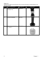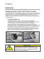
1
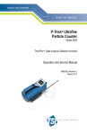
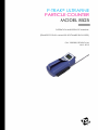
P-TRAK® ULTRAFINE PARTICLE COUNTER MODEL 8525 OPERATION AND SERVICE MANUAL (TRAKPRO™ DATA ANALYSIS SOFTWARE ENCLOSED) P/N 1980380, REVISION M JULY 2013 P-TRAK® ULTRAFINE PARTICLE COUNTER MODEL 8525 OPERATION AND SERVICE MANUAL (TRAKPRO™ DATA ANALYSIS SOFTWARE ENCLOSED) P/N 1980380, REVISION M JULY 2013 SHIP TO/MAIL TO: TSI Incorporated 500 Cardigan Road Shoreview, MN 55126-3996 USA U.S. Technical Support: (800) 874-2811/(651) 490-2811 Fax: (651) 490-3824 E-mail: [email protected] E-mail address: [email protected] Website: http://www.tsi.com INTERNATIONAL Technical Support: (001 651) 490-2811 Fax: (001 651) 490-3824 E-mail: [email protected] Copyright © TSI Incorporated / 1999–2013 / All rights reserved. Address TSI Incorporated / 500 Cardigan Road / Shoreview, MN 55126 / USA Fax No. (651) 490-3824 LIMITATION OF WARRANTY AND LIABILITY (effective June 2011) (For country-specific terms and conditions outside of the USA, please visit www.tsi.com.) Seller warrants the goods sold hereunder, under normal use and service as described in the operator's manual, shall be free from defects in workmanship and material for 24 months, or if less, the length of time specified in the operator's manual, from the date of shipment to the customer. This warranty period is inclusive of any statutory warranty. This limited warranty is subject to the following exclusions and exceptions: a. Hot-wire or hot-film sensors used with research anemometers, and certain other components when indicated in specifications, are warranted for 90 days from the date of shipment; b. Pumps are warranted for hours of operation as set forth in product or operator’s manuals; c. Parts repaired or replaced as a result of repair services are warranted to be free from defects in workmanship and material, under normal use, for 90 days from the date of shipment; d. Seller does not provide any warranty on finished goods manufactured by others or on any fuses, batteries or other consumable materials. Only the original manufacturer's warranty applies; e. Unless specifically authorized in a separate writing by Seller, Seller makes no warranty with respect to, and shall have no liability in connection with, goods which are incorporated into other products or equipment, or which are modified by any person other than Seller. The foregoing is IN LIEU OF all other warranties and is subject to the LIMITATIONS stated herein. NO OTHER EXPRESS OR IMPLIED WARRANTY OF FITNESS FOR PARTICULAR PURPOSE OR MERCHANTABILITY IS MADE. WITH RESPECT TO SELLER’S BREACH OF THE IMPLIED WARRANTY AGAINST INFRINGEMENT, SAID WARRANTY IS LIMITED TO CLAIMS OF DIRECT INFRINGEMENT AND EXCLUDES CLAIMS OF CONTRIBUTORY OR INDUCED INFRINGEMENTS. BUYER’S EXCLUSIVE REMEDY SHALL BE THE RETURN OF THE PURCHASE PRICE DISCOUNTED FOR REASONABLE WEAR AND TEAR OR AT SELLER’S OPTION REPLACEMENT OF THE GOODS WITH NON-INFRINGING GOODS. TO THE EXTENT PERMITTED BY LAW, THE EXCLUSIVE REMEDY OF THE USER OR BUYER, AND THE LIMIT OF SELLER'S LIABILITY FOR ANY AND ALL LOSSES, INJURIES, OR DAMAGES CONCERNING THE GOODS (INCLUDING CLAIMS BASED ON CONTRACT, NEGLIGENCE, TORT, STRICT LIABILITY OR OTHERWISE) SHALL BE THE RETURN OF GOODS TO SELLER AND THE REFUND OF THE PURCHASE PRICE, OR, AT THE OPTION OF SELLER, THE REPAIR OR REPLACEMENT OF THE GOODS. IN THE CASE OF SOFTWARE, SELLER WILL REPAIR OR REPLACE DEFECTIVE SOFTWARE OR IF UNABLE TO DO SO, WILL REFUND THE PURCHASE PRICE OF THE SOFTWARE. IN NO EVENT SHALL SELLER BE LIABLE FOR LOST PROFITS OR ANY SPECIAL, CONSEQUENTIAL OR INCIDENTAL DAMAGES. SELLER SHALL NOT BE RESPONSIBLE FOR INSTALLATION, DISMANTLING OR REINSTALLATION COSTS OR CHARGES. No Action, regardless of form, may be brought against Seller more than 12 months after a cause of action has accrued. The goods returned under warranty to Seller's factory shall be at Buyer's risk of loss, and will be returned, if at all, at Seller's risk of loss. ii Buyer and all users are deemed to have accepted this LIMITATION OF WARRANTY AND LIABILITY, which contains the complete and exclusive limited warranty of Seller. This LIMITATION OF WARRANTY AND LIABILITY may not be amended, modified or its terms waived, except by writing signed by an Officer of Seller. Service Policy Knowing that inoperative or defective instruments are as detrimental to TSI as they are to our customers, our service policy is designed to give prompt attention to any problems. If any malfunction is discovered, please contact your nearest sales office or representative, or call TSI at (800) 874-2811 (USA) or (001 651) 490-2811 (International). Trademarks TSI, TSI logo, and P-Trak are registered trademarks of TSI Incorporated. TrakPro is a trademark of TSI Incorporated. Microsoft and Windows are registered trademarks of Microsoft Corporation. iii (This page intentionally left blank) iv CONTENTS SAFETY INFORMATION .................................................................. VII 1 UNPACKING AND PARTS IDENTIFICATION ............................ 1 Unpacking the P-Trak® Ultrafine Particle Counter ........................ 1 Optional Accessories..................................................................... 4 Spare/Replacement Parts ............................................................. 5 2 SETTING UP ................................................................................. 7 Supplying Power to the P-Trak® Particle Counter ......................... 7 Installing the Batteries ................................................................ 7 Using the AC Adapter ................................................................ 8 Charging and Installing the Alcohol Wick ...................................... 9 Cautions Before Proceeding ...................................................... 9 Locating and Identifying Components...................................... 10 Filling the Alcohol Fill Capsule ................................................. 10 Installing the Cartridge into the P-Trak Particle Counter ......... 12 Cleaning Up and Final Cautions .............................................. 13 Attaching the Inlet Screen Assembly, Sample Tube, and Telescoping Probe to the Instrument ....................................... 13 Instrument Software and Communications Setup ....................... 15 Setting up TrakPro™ Data Analysis Software ......................... 15 Connecting the P-Trak Particle Counter to the Computer ....... 16 Setting up the Communications Port ....................................... 16 Connecting the Optional Portable Printer.................................... 17 3 OPERATION ............................................................................... 19 Overview...................................................................................... 19 Turning the Instrument On .......................................................... 19 Tilting the Instrument ................................................................... 20 Daily Zero Check ......................................................................... 21 P-Trak Particle Counter Keypad .................................................. 21 Main Menu ................................................................................... 22 Particle Concentration .............................................................. 22 Sample Mode ........................................................................... 22 Recording and Saving a Single Data Point .............................. 23 Changing the Location Label .............................................. 24 Setup Mode .............................................................................. 24 Statistics .............................................................................. 24 Logged Test Statistics ..................................................... 25 Single Point Statistics ...................................................... 26 Log Interval .......................................................................... 26 Audio ................................................................................... 27 Time/Date ............................................................................ 28 Programming Time/Date Using TrakPro Software .............. 29 Backlight .............................................................................. 29 Clear Memory ...................................................................... 30 v LOG MODE .............................................................................. 31 Log Mode 2 and 3 ........................................................................ 32 Sample Protocol for Log Mode 2 or 3 .......................................... 35 Memory Considerations............................................................... 38 Particle Sampling Configurations ................................................ 38 Sampling Through Inlet Screen, Tube, and Probe Assembly .. 39 Sampling Through Inlet Screen and Sample Tube .................. 39 Sampling Through Inlet Screen Assembly Only ...................... 40 4 MAINTENANCE .......................................................................... 41 Maintenance Schedule ................................................................ 41 Daily Zero Check ......................................................................... 42 Recharging the Alcohol Wick ...................................................... 42 Alcohol Cartridge ......................................................................... 42 Changing the Alcohol Wick ...................................................... 42 Removing the Wick from the Cartridge .................................... 43 Re-assembling the Alcohol Cartridge....................................... 44 Cleaning Inlet Screen Assembly ................................................. 45 5 TROUBLESHOOTING ................................................................ 47 6 CONTACTING CUSTOMER SERVICE ...................................... 51 Technical Contacts ...................................................................... 51 Returning the Model 8525 P-Trak Particle Counter for Service .. 52 A SPECIFICATIONS....................................................................... 53 B MATERIAL SAFETY DATA SHEET: ISOPROPYL ALCOHOL 55 Application Notes can be found on TSI’s web site: http://www.tsi.com vi Contents Safety Information When operated according to the manufacturer’s instruction, this device is a Class I laser product as defined by U.S. Department of Health and Human Services standards under the Radiation Control for Health and Safety Act of 1968. A certification and identification label like the one shown below is affixed to each instrument. CLASS CLASS 11 LASER LASERPRODUCT PRODUCT THIS THISPRODUCT PRODUCTIS ISIN IN COMPLETE COMPLETE COMPLIANCE WITH COMPLIANCE WITH21 21CFR CFR 1040.10 1040.10AND AND1040.11 1040.11 There are no user-serviceable parts inside this instrument. Performing services other than those described in this manual may result in exposure to harmful (invisible) laser radiation. A warning label like the one shown below is affixed to the internal laser device. DANGER: INVISIBLE LASER RADIATION WHEN OPEN. AVOID DIRECT EXPOSURE TO BEAM. WARNING: NO USER SERVICEABLE PARTS INSIDE. REFER SERVICING TO QUALIFIED PERSONNEL. vii (This page intentionally left blank) viii Safety Information Chapter 1 Unpacking and Parts Identification Unpacking the P-Trak® Ultrafine Particle Counter Carefully unpack the Model 8525 P-Trak Ultrafine Particle Counter from the shipping container. Use the tables and illustrations below to make certain that there are no missing components. Contact TSI immediately if anything is missing or damaged. Table 1-1 Model 8525 P-Trak Ultrafine Particle Counter With Inlet Probe Assembly, Battery Pack, and Batteries Qty. 1 Part/Model N/A 1 6 Item Description P-Trak Ultrafine Particle Counter Probe assembly, consisting of telescoping probe, sample tube, and inlet screen assembly Battery holder Battery, AA, alkaline 1 Carrying case 801613 1 Reference 801622 801615 801616 801623 N/A (not shown) 1 Table 1-2 Alcohol Fill Capsule with Storage Cap, Alcohol Cartridge, Alcohol Bottles and Shoulder Strap Qty. 1 Item Description Alcohol fill capsule and storage cap. Part/Model 1083070 1 Alcohol cartridge 801624 16 30 ml alcohol bottles (1 shown) 2918011 2 Reference Chapter 1 Table 1-3 Mesh Storage Bag with Spare Wicks, Computer Cable, Zero Filters, and DB9/DB25 Adapter Qty. 1 Item Description Mesh bag Part/Model N/A 2 Spare wick kit N/A 1 Computer cable, RJ45/DB9 800563 2 HEPA zero filter, with adapter 801625 1 USB to RS-232 Converter 1102138 Unpacking and Parts Identification Reference 3 Table 1-4 Calibration Certificate, Operation and Service Manual, TrakPro Software Qty. 1 Item Description Calibration Certificate Part/Model N/A 1 Operation and Service Manual 1980380 1 TrakPro Software 1090014 Reference Optional Accessories The following table lists optional accessories available for the P-Trak Ultrafine Particle Counter. Quantity 1 1 4 Item Description AC adapter for P-Trak particle counter (115V only) Portable printer Chapter 1 Spare/Replacement Parts The following items may be purchased as spare or replacement parts. Item Description Alcohol wicks with screens (Pkg. of 10) Tubing, sample, 4’ x 18”, Tygon Inlet screen assembly Alcohol, 16 qty., 30 ml bottles Unpacking and Parts Identification Part Number 8023 801615 801616 2918011 5 (This page intentionally left blank) 6 Chapter 1 Chapter 2 Setting Up Supplying Power to the P-Trak® Particle Counter The Model 8525 P-Trak Ultrafine Particle Counter may be powered in one of two ways. The standard configuration instrument is sold with a battery holder containing 6, AA alkaline batteries. An optional AC adapter may also be used to power the instrument when operating in a fixed location. Installing the Batteries To install the battery holder, first install the 6 individual AA batteries into the pack, noting the battery polarity as marked on the inside of the battery holder. Remove the battery compartment door by pressing in and pulling out on the two locking tabs. Next, install the battery pack (battery side down) into the battery compartment as shown in Figure 2-1, putting the top of the pack (the side with the two contacts extending from the body of the pack) down first and snapping the rest of the pack in place. Finally, replace the battery compartment door. Figure 2-1: Install Battery Pack into Battery Compartment CAUTION Avoid forcing the battery pack into place. The battery pack fits correctly in only one orientation. When installed properly, the batteries will face down into the compartment. 7 1 2 3 4 5 6 Figure 2-2: The Back of the Instrument 1. On/Off switch 2. Inlet quick-connect fitting 3. Communications port 4. AC Adapter socket 5. Headphone jack 6. Alcohol cartridge Using the AC Adapter The AC adapter allows you to power the P-Trak particle counter from an AC wall outlet. When using the AC adapter, the batteries (if installed) will be bypassed. The AC adapter will not charge the batteries. The P-Trak particle counter has an internal, non-user accessible battery that is used for battery back-up of logged data when the instrument is turned off. Removing/changing the alkaline batteries or disconnecting the AC adapter will not cause data to be lost. This backup battery will last for years. TSI will install a new battery, if necessary, when the unit is returned to the factory for service. 8 Chapter 2 Charging and Installing the Alcohol Wick Cautions Before Proceeding WARNING Isopropyl Alcohol is hazardous material. Do not ingest or allow alcohol to contact your eyes or skin. Refer to the Material Safety Data Sheet (MSDS) located in the box of alcohol and in Appendix B of this manual for handling precautions and first aid procedures. Note: Always recap alcohol containers immediately to prevent absorption of moisture and the escape of fumes. Caution The CO sensor in some models of TSI IAQ monitors may be adversely affected when exposed to isopropyl alcohol vapors released from TSI instruments utilizing condensation particle counting (CPC) technology. For maximum performance, keep CO sensors away from CPC-based instruments utilizing isopropyl alcohol. The P-Trak particle counter consumes high-purity isopropyl alcohol at a rate of about 1 ml per hour. The alcohol is used to grow microscopic particles in the air into larger droplets that are easier to detect and count. The isopropyl alcohol that is required to properly operate the P-Trak particle counter must be very high purity "reagent grade" alcohol. Isopropyl alcohol that is available from pharmacies, drug stores, or other consumer outlets is low purity and usually contains significant percentages of water and other substances that can damage the P-Trak particle counter. Note It is essential to use isopropyl alcohol that is 99.5% pure or better. Do not use isopropyl alcohol from any source other than TSI or a TSI-approved supplier. Problems caused by the use of unapproved alcohol are not covered under warranty. Maintaining an adequate alcohol supply inside the Condensation Particle Counter is critical to its operation and requires strict adherence to the directions that follow. Setting Up 9 Locating and Identifying Components To add alcohol to the P-Trak particle counter, first identify and locate the alcohol related components and accessories that are included with the instrument (refer to Table 1-2, for more information). You will need the following items: Isopropyl Alcohol Alcohol Fill Capsule Storage Cap Alcohol Cartridge Isopropyl alcohol is supplied by TSI in 30 ml plastic bottles. The alcohol fill capsule is located in the carrying case. The alcohol cartridge will also be either in the P-Trak cartridge cavity or in the alcohol fill capsule, whichever one is not holding the storage cap. The storage cap should be either sealing the alcohol fill capsule or inserted into the P-Trak cartridge cavity. Filling the Alcohol Fill Capsule 1. Turn the P-Trak particle counter off. 2. Open the alcohol fill capsule by twisting the storage cap (or alcohol cartridge) 18 turn counter-clockwise. Set the storage cap (or alcohol cartridge) down on a clean surface, with the end standing up, as shown in Figure 2-3. Figure 2-3: Alcohol Cartridge and Storage Cap 10 Chapter 2 3. Open a bottle of alcohol. Invert the bottle and insert the nozzle end into the alcohol fill capsule as far as possible to make certain that you cannot inadvertently spray alcohol anywhere except down into the capsule. Fill Line Figure 2-4: Alcohol Fill Capsule 4. Squeeze alcohol into the alcohol fill capsule until the liquid level is even with the scribed fill-line near the base (Figure 2-4). Recap the alcohol bottle. 5. Make certain the alcohol cartridge is clean! Insert the alcohol cartridge into the alcohol fill capsule by aligning the groove with the pin and turning 18 turn (clockwise) until it locks into place (Figure 2-5). Figure 2-5: Insert Alcohol Cartridge into Fill Capsule Setting Up 11 6. Set the alcohol fill capsule down and wait a few minutes while the wick inside the cartridge soaks up alcohol. Installing the Cartridge into the P-Trak Particle Counter 1. Remove the alcohol cartridge from the fill capsule and gently shake it to allow excess alcohol to drain back into the capsule. Stop when excess alcohol is no longer dripping. It is not necessary to wait until the outside surface of the alcohol cartridge is dry. 2. Insert the cartridge into the cartridge cavity on the P-Trak particle counter. It should slide in easily with little effort. Do not force it! Align the tab on the alcohol cartridge with the corresponding tab on the P-Trak particle counter, located just above the cartridge cavity. 3. As you approach full insertion, firmly twist the alcohol cartridge clockwise about 18 turn. It should snap into position. Figure 2-6: Insert Alcohol Cartridge into P-Trak Particle Counter 12 Chapter 2 Cleaning Up and Final Cautions 1. Recap the alcohol fill capsule using the storage cap. Note: Always recap the alcohol fill capsule and other containers immediately to prevent absorption of moisture and the escape of fumes. Dispose of any alcohol that is visibly contaminated. 2. When the P-Trak particle counter is stored in the carrying case, you should store the alcohol cartridge in the alcohol fill capsule. The alcohol fill capsule is designed to be a safe transportation and storage container for alcohol. The alcohol cartridge can be left soaking in alcohol indefinitely. Also, install the storage cap into the cartridge cavity to prevent dirt or lint from getting inside the P-Trak particle counter. 3. Never transport or store the P-Trak particle counter with the alcohol cartridge inside it. Flooding of the optics could occur. 4. Always keep the alcohol cartridge clean. 5. Never leave the cartridge cavity open longer than necessary. Use the storage cap to cover the cartridge cavity when the PTrak particle counter is transported or stored. 6. Keep the storage cap and alcohol cartridge clean. Always set them down with the end standing up. These precautions prevent dirt or debris from entering the instrument and causing operational problems. Attaching the Inlet Screen Assembly, Sample Tube, and Telescoping Probe to the Instrument The normal sampling configuration for the P-Trak Ultrafine Particle Counter consists of the inlet screen assembly, sample tube, and telescoping probe (see Chapter 3, “Operation,” for information on other sampling options). The inlet screen assembly helps to prevent large particles and fibers from entering the instrument and plugging the internal fittings. Do not operate the P-Trak particle counter without the inlet screen assembly in place. To attach the sampling assembly: 1. Make sure the quick-connect fitting is in the “unlocked” position. If the fitting is locked, the sampling tube will not be able to be inserted into the instrument. To unlock the fitting, press up on the tab under the fitting. Setting Up 13 2. Insert the inlet screen assembly into the fitting and press it firmly until it snaps into place (see Figure 2-7). It may help to rotate the inlet screen while inserting. 3. Attach one end of the sample tube to the inlet screen assembly barbed fitting. 4. Attach the other end of the sample tube to the barbed fitting on the telescoping probe. Figure 2-7: Insert Inlet Screen Assembly into Fitting 5. For storage and safe keeping, attach the telescoping probe to either side of the instrument. Slide it in lengthwise along the instrument, beginning at the back of the instrument (the alcohol wick end) until it stops (do not force it!). See Figure 2-8. 14 Chapter 2 Figure 2-8: Slide Telescoping Probe onto Instrument Case The P-Trak particle counter is now ready to operate. Refer to Chapter 3, “Operation,” for information on starting and operating the instrument. The remainder of this chapter contains information on optional setup routines. Instrument Software and Communications Setup The P-Trak particle counter comes with special software called TrakPro software, which is designed to provide you with maximum flexibility and power when using the P-Trak particle counter. The following sections describe how to install the software and set up the computer. Setting up TrakPro™ Data Analysis Software Follow the instructions on the label of TrakPro Software to install the software on your computer. TrakPro software contains a very comprehensive Help Function. This utility provides all the necessary information to guide you in all aspects of software operation. Setting Up 15 Connecting the P-Trak Particle Counter to the Computer Each P-Trak particle counter comes equipped with an RS-232 cable and a 25-pin to 9-pin serial cable adapter. One end of the cable is a 25-pin D subminiature connector labeled COMPUTER; the other end is an RJ-45 modular connector that connects with the P-Trak communications port. Serial port connectors always have pins (male) on the computer side. 1. Locate an available RS-232 serial port on your computer: for example, COM1 or COM2. 2. If the port has a 9-pin connector, you do not need the adapter. If the port has a 25-pin connector, plug the 9-pin end of the adapter into the RS-232 cable. 3. Connect the RS-232 cable to the available serial port on your computer. 4. Connect the RJ-45 connector to the P-Trak communications port. Setting up the Communications Port To communicate with the P-Trak particle counter, the software must be configured for the proper COM port. TrakPro software can be manually set to operate on a specific COM port, or it can automatically find a P-Trak particle counter that is attached to any COM port. To set up the COM port, do the following: 1. Turn on the P-Trak particle counter. 2. Start TrakPro software. 3. Select Instrument Setup, Communications in TrakPro software. The following dialog is displayed: Figure 2-9: Instrument Setup, Communications Dialog Box 16 Chapter 2 4. Select the correct serial port (such as, COM1); then select Test. The software will verify that you have set up the communications port correctly and that it is communicating with the P-Trak particle counter. The system displays an information message indicating whether it was able to establish communications. 5. As an alternate, you may select Find Port, to have TrakPro software search the available COM ports, looking for an attached P-Trak particle counter. 6. Select OK to accept the setup, or Cancel to discard the changes. Connecting the Optional Portable Printer To connect the portable printer to the P-Trak particle counter, do the following: 1. Ensure that the P-Trak particle counter and printer are off. 2. Locate the printer interface cable and connect the 9-pin end labeled PRINTER to the printer and the other end to the communications port on the P-Trak particle counter. 3. Turn on the P-Trak particle counter; then turn on the printer. Note: Always turn on the P-Trak particle counter before turning on the printer. If the printer prints question marks (??????), asterisks (******), or random characters, reset it by turning it off and then on again. If necessary, refer to the Portable Printer Manual. Setting Up 17 (This page intentionally left blank) 18 Chapter 2 Chapter 3 Operation Overview The P-Trak particle counter has three main modes of operation, Survey, Sample, and Data Log. Survey mode: When the P-Trak particle counter is first turned on, it will be in Survey mode which is used to display real-time particle concentration readings, in particles per cubic centimeter (pt/cc). The instrument will update the displayed concentration once each second. This is the most common mode of operation and is used to track sources of ultrafine particles. Sample mode: The Sample mode is used to take a 10-second, averaged particle concentration reading. These single data points may be stored in memory and annotated. Data Log mode: The Data Log mode is used to record particle concentration readings over a period of time, and store these readings in the instrument memory. Data files may be downloaded to a computer for later analysis using TrakPro software. Turning the Instrument On Press the ON/OFF switch (located at the back of the instrument) and hold for 2 to 3 seconds to turn on the P-Trak particle counter. The instrument immediately begins a warm-up, countdown sequence, which takes about 60 seconds. During the warm-up time, the instrument is powering the internal components and coming up to operating temperature. A screen will be displayed identifying the instrument model number and the firmware revision level. 19 Tilting the Instrument CAUTION To prevent false counts and/or a temporary loss of counting efficiency, the P-Trak particle counter must be held in a substantially level position during operation. Prolonged operation while tilted can cause alcohol within the instrument to flood the optics. This may result in the need for factory cleaning and servicing. The P-Trak particle counter contains liquid isopropyl alcohol, which is absorbed into a porous wick. Under most operating conditions, the alcohol remains absorbed in the wick. However, if the instrument is tilted for a period of time, the alcohol will slowly seep out of the wick. This liquid alcohol may be drawn into the optical chamber, causing false particle counts and possibly flooding the optics. This will not permanently damage the instrument, but may result in a temporary loss of performance. To avoid this problem, please observe the following cautions: Do not tilt the instrument up (into a vertical position) to observe the display. If the instrument is tilted for more than 4 seconds: a tilt error message will be displayed, the beeper will sound, the displayed particle concentration will “blank out” and the pump will be stopped. After restoring the instrument to level operation, the tilt error condition will correct itself (the pump will restart and the display will reset). If the instrument is tilted during data logging, the instrument may shut down and discontinue logging. If the instrument is tilted during the Sample mode, the data point will be discarded. 20 Chapter 3 Daily Zero Check Before beginning to sample with the P-Trak particle counter, it is important to verify that the instrument is operating normally. This Daily Zero Check should be performed at least once a day. 1. Turn on the instrument and let it warm up (approximately 60 seconds). 2. Remove the sample tube from the inlet screen assembly (if attached). 3. Attach the supplied zero filter assembly (Table 1-3) to the inlet screen assembly. 4. The particle concentration should go to zero in approximately 5 to 10 seconds. Leave the zero filter attached to the instrument for 30 seconds, to make sure the zero reading is stable. Note: If the instrument does not go to zero, please refer to Chapter 5, Troubleshooting, for more information. The Daily Zero Check cannot be performed when the telescoping sample probe is attached to the instrument. The telescoping joints will cause a small number of particles to be sampled and will invalidate the zero check. 5. Remove the zero filter. Attach the sample tube and telescoping sample probe, as desired. The instrument is now ready for operation. P-Trak Particle Counter Keypad The P-Trak particle counter is controlled using a simple, 4-way keypad, with Up, Down, Left, and Right keys along with an Enter key. These keys are used to move between menu items, to increase or decrease selected values and to select the desired item/value. When pressing the keys on the front panel, the P-Trak particle counter beeps to confirm the function. See Figure 3-1. Operation Figure 3-1: P-Trak Particle Counter Keypad and Display 21 Main Menu After the instrument has completed its warm-up countdown, the P-Trak particle counter will automatically go into the Survey mode and the Main Menu will be displayed. 1 2 3 3670 PT CC SAMPLE SETUP LOG MODE 1 5 4 Figure 3-2: Main Menu Screen (sample) Ref 1 2 3 4 5 Description Particle concentration, in units of particles per cubic centimeter. Sample mode. Used for capturing single data points. Setup mode. Used for reviewing logged data, single data points, statistics. Used for changing date/time, log interval, backlight interval, audio function. Used for clearing memory. Log mode (recording data files). Displays current log mode (1, 2, or 3). Used for changing mode and starting data logging. Status area of Main Menu. Used for displaying status and error messages. Particle Concentration The P-Trak particle counter displays the measured particle concentration in units of particles per cubic centimeter (pt/cc). The display updates once per second. The instrument range is from 0 to 500,000 pt/cc. Sample Mode The SAMPLE mode is the default selection on the Main Menu (the reverse highlight indicates that it is selected). The Sample mode is used to capture a single, 10-second averaged data point. Instantaneous particle concentrations often fluctuate significantly. When making a measurement, therefore, it is often desirable to dampen out these fluctuations with a short averaging period. 22 Chapter 3 Recording and Saving a Single Data Point When you press “ ”, with the Sample mode highlighted, the P-Trak particle counter begins a countdown. During these 10 seconds, it is taking an average reading of the particle concentration. At the end of the averaging period, the following sample screen is displayed: 3678 PT CC RECORD VALUE IN MEMORY? YES NO Figure 3-3: Record Single Data Point The YES selection is highlighted by default. If you press “”, the single data point will be stored in memory. If you scroll down to NO, the data point will be discarded. Operation 23 Changing the Location Label Once you choose to save the data point in memory, the P-Trak particle counter displays the EDIT LOCATION screen. The instrument gives the data point a default name, starting with “LOCATION 01.” The following screen is displayed. -EDIT LOCATION- LOCATION 01 PRESS TO EXIT Figure 3-4: Edit Location Label, Single Data Point If you press “ ”, the instrument will save the data point with the default Location Name (in this case, “Location 01”). If desired, you may change the Location name, up to a maximum of 15 alpha/numeric characters. When done editing, press “ ” to exit and save. The instrument will return to the Survey mode. Setup Mode The Setup mode gives you access to a wide range of options for reviewing data, examining statistics and changing operational parameters. When SETUP is selected and “” is pressed, the program opens the Setup menu, as shown below: STATISTICS LOG INTERVAL AUDIO TIME/DATE BACKLIGHT CLEAR MEMORY EXIT Figure 3-5: Setup Menu Statistics The STATISTICS selection gives you access to a sub-menu, which provides a choice of either Logged Test Statistics or Single Point Statistics. 24 Chapter 3 Logged Test Statistics The Logged Test Statistics screen allows you to review a statistical summary of each data logged test. When the screen is first displayed, it will show the statistics for the most recent test. You may page through and review the statistics for each test in memory. A sample screen is shown below. -LOGGED TEST STATSTEST #3 START: 08:23 11/02/2012 STOP: 09:45 11/02/2012 MIN: 3753 09:35:00 MAX: 3753 09:35:05 AVG: 4052 PRESS WHEN DONE 1 2 3 4 5 6 Figure 3-6: Logged Test Statistics Ref 1 2 3 4 5 6 Description Test number (not user adjustable). Start time and date. Stop time and date. Minimum value during test, along with time at which minimum occurred. Maximum value during test, along with time at which maximum occurred. Average value during logged test, in pt/cc. Operation 25 Single Point Statistics The Single Point Statistics screen allows you to review a statistical summary of each recorded single data point. When the screen is first displayed, it will show the information for the most recent single data point. You may page through and review the information for each recorded point. A sample screen is shown below. -SINGLE POINT STATSLOCATION 01 3760 PT/CC 08:22:34 11/02/2012 PRESS WHEN DONE Figure 3-7: Single Point Statistics Log Interval The Log Interval menu allows you to view the current logging interval used during LOG MODE 1 (see “Log Mode 2 and 3” section, later in this chapter, for more information about data logging). It also allows you to adjust the log interval to a different value. The menu screen is shown below. -LOG INTERVAL- 01:00 MIN:SEC Figure 3-8: Log Interval The default values for log intervals are set at 1 second, 1 minute, 5 minutes, 15 minutes and 30 minutes. When “” is pressed, the program retains the current setting and returns to the Setup menu. The log interval is both a frequency and an averaging period. For example, when the log interval is set to 5 minutes, readings will be recorded at 5-minute intervals. Each reading will be the average value measured over that 5-minute interval. 26 Chapter 3 The log interval options for LOG MODE 1 may also be programmed using TrakPro software. Select Instrument Setup, Parameters, then Logging Intervals, from the TrakPro software menu. The current settings in the P-Trak particle counter will be retrieved and displayed in the dialog box. You may program in new values for each of the five log intervals (within defined limits). Select Send to program the P-Trak particle counter with the new values. Note: This log interval only applies to Log 1 mode, initiated from the instrument keypad. The log interval for Log 2 and Log 3 modes is adjustable only within TrakPro software. Audio The Audio Output feature on the P-Trak particle counter provides an audible feedback which is proportional to the measured particle concentration. When this feature is turned On, you will hear an audio signal which will give you an indication of changing particle concentrations. This feature may be particularly useful when you are attempting to detect highly localized sources of particulate, in a low light condition. A sample screen is shown below. -AUDIO OUTPUT5600 PT/CC OFF CAPTURE REFERENCE SET REFERENCE: 3040 EXIT Figure 3-9: Audio Output The Audio menu allows you to turn the audio output feature OFF/ON and to adjust characteristics of this feature. Note the following characteristics of this function: The current, real time particle concentration is displayed at the top of the display. The Audio function is turned OFF by default. To turn it ON, use the left/right arrow keys. To adjust the reference value to the same as the current ambient concentration, highlight the CAPTURE REFERENCE selection, and press “”. You will notice that the real time value and reference value become essentially equal. Operation 27 To adjust the reference value manually, move the selection highlight to SET REFERENCE. Then, use the right arrow key to move the highlight to the reference value. Use the up/down arrow to adjust the reference values in increments of 100. When satisfied with the new reference value, use the left arrow key to return to SET REFERENCE. When all adjustments are completed, highlight the EXIT selection and press “”. This will return you to the SETUP menu. Time/Date The P-Trak particle counter has an internal clock that keeps track of the time of day and the date. The format is HH:MM:SS where HH is the hour in 24-hour format, along with minutes and seconds. It is very important for the P-Trak particle counter to have the time and date correctly set; otherwise, time and date stamping of recorded data will not be correct. The time clock is set correctly at the factory (for U.S. Central Standard Time). If it requires adjustment, it may be changed by selecting TIME/DATE from the Setup menu. The following screen is displayed: -TIME/DATEUSE <> FOR POSITION USE ^ FOR VALUE HH:MM:SS 08:25:32 MM/DD/YYYY 11/02/2012 Figure 3-10: Time/Date When first entering this screen, the first character in the hour (HH) field will have a cursor underneath it. Use the up/down arrows to increment and/or decrement values. Use the left/right arrows to move to the required field. When all adjustments are complete, press the “” key to accept the changes and return to the Setup menu. 28 Chapter 3 Programming Time/Date Using TrakPro Software The time and date may also be adjusted using TrakPro software. To program the P-Trak particle counter date and time: 1. Make sure the P-Trak particle counter is connected to the computer and turned on. 2. In TrakPro software, select Parameters, then Clock from the Instrument Setup menu. TrakPro software retrieves the current date and time settings from P-Trak particle counter and displays them in the following dialog: Figure 3-11: Time/Date Programming with TrakPro Software 3. The system date and time (from the computer) can be transferred to the P-Trak particle counter using the “arrows” keys. Alternately, the date and time can be manually entered into the dialog box. 4. Select Send to reprogram the P-Trak particle counter. Backlight The BACKLIGHT option on the Setup menu allows you to adjust how long the display backlight stays on after a key is pressed or an alarm occurs. After the delay, the backlight automatically turns off. To change the backlight delay, use the Up/Down arrows. The options are: No Backlight; 5, 10 and 30 seconds. Press “” to select the value and return to the Setup Menu. Operation 29 -BACKLIGHT DELAY- 5 SECONDS Figure 3-12: Backlight Delay Note: Prolonged use of the backlight may severely reduce the overall battery life. To edit the backlight delay using TrakPro software, select Instrument Setup, Parameters, and Other. Follow the onscreen prompts or open the Help Function (F1) for more information. Clear Memory The CLEAR MEMORY option on the Setup menu allows you to clear the instrument memory. To preserve data integrity, the P-Trak particle counter does not automatically erase the “older” data files. It requires a deliberate step, on your part, to clear the memory. Note: Performing this step will erase all logged data files and/or recorded single data points from the instrument memory. There is no reversing this step, once it is performed! To clear the memory, select the CLEAR MEMORY option on the Setup menu. After pressing “”, the following screen is displayed. -CLEAR MEMORYSINGLE POINT MEMORY LOGGED TEST MEMORY EXIT Figure 3-13: Clear Memory Select Screen 30 Chapter 3 The highlighted default selection is Single Point Memory. If you press “” at this point, the Single Point Memory will be erased (the Logged Test Memory will be unaffected). Logged Test Memory is cleared in the same manner. LOG MODE The third selection on the Main menu allows you to select which data logging mode to use and then to initiate a data logging session. To make changes to the LOG MODE, simply scroll Up/Down to the LOG MODE 1 selection and then adjust the mode using the Left/Right arrows. You may select LOG MODE 1, 2, or 3 (please see the section on “Log Mode 2 and 3,” later in this chapter, for more information about these programmable log modes). The logging interval for LOG MODE 1 must be adjusted, from the Setup menu, before beginning the logging session. To begin a data logging session, select the LOG MODE and press “”. The P-Trak particle counter will begin recording logged data into the instrument memory. If LOG MODE 1 was selected, the following screen will be displayed: 4048 MIN 4032 MAX 4950 LOG MODE 1 PT CC 08:32:00 09:27:00 98 % MEM TO STOP Figure 3-14: Log Mode 1 If LOG MODE 2 or 3 was selected, the P-Trak particle counter may or may not begin logging immediately, depending upon the setup parameters. See “Log Mode 2 and 3,” in this chapter, for more information. Operation 31 Log Mode 2 and 3 The P-Trak particle counter may be programmed for more sophisticated data logging modes, using TrakPro software and Log Modes 2 and 3. With Log Modes 2 and 3, you can set the start date, start time, test length, logging interval, number of tests, and the time delay between tests. You program the logging protocols into the P-Trak particle counter using the power and simplicity of TrakPro software. The instrument is then taken to the field, where you simply select Log Mode 2 or Log Mode 3, and begin data logging. To program a logging protocol for Log Mode 2 or 3: 1. Make sure the P-Trak particle counter is connected to the computer and turned on. 2. Select Logging Setup from the Instrument Setup menu. TrakPro software retrieves the current settings for Log Modes 2 and 3 from the P-Trak particle counter and displays them in the following dialog box. Figure 3-15: P-Trak Particle Counter Logging Protocols 32 Chapter 3 The following table summarizes the information displayed in the P-Trak particle counter Logging Protocol dialog box. Item Description Serial Number Displays the serial number of the P-Trak particle counter. Number of tests logged Displays the number of tests currently logged and stored in the logging instrument. Available Memory % Displays the percent of available memory in the P-Trak particle counter (data logging only; single point memory is not included in this total). Channels Displays the channels selected for sampling in LOG 2 and LOG 3 modes (for the P-Trak particle counter, this is limited to particle concentration). Start Date Displays the start date for LOG 2 and LOG 3 modes. Start Time Displays the start time for LOG 2 and LOG 3 modes. Log interval Displays the log interval for LOG 2 and LOG 3 modes. Test length Displays the test length for LOG 2 and LOG 3 modes. Number of tests Displays the number of tests for LOG 2 and LOG 3 modes. Selecting more than one test will cause the instrument to cycle through the logging test more than once, separated by the “Time Between Tests.” Time between tests Displays the time between tests for LOG 2 and LOG 3 modes. Percent memory required Displays the percent of logger memory required to perform a LOG 2 or a LOG 3 mode sample. To store the results of a LOG 2 or LOG 3 mode sample, the Available Memory must be equal to or greater than the Percent memory required. Operation 33 To program the P-Trak particle counter for Log Mode 2 or 3, do the following: Item Description Channels Select the channels for which you want to log data. In the case of the P-Trak particle counter, there is only one channel to select: particle concentration. Start Date Start Time Enter the date and time to begin the sample: If you enter a blank for a start date, the sample begins whenever the specified start time occurs. If you enter a blank for the start time, both start date and start time are ignored, and the sample begins when the operator manually starts the sample. Log interval Enter the log interval to use for the test. Test length Enter the length for the sample: If you enter a value, the instrument automatically turns off when the last test is complete. If you enter a blank, the operator must manually stop the sample. Number of tests Enter the number of tests to perform. Time between tests If you have specified more than one Number of tests, enter the time between tests. If you enter 0 or blank, the next test is started immediately after the last test is complete. While you are entering values for Log Mode 2 or 3, the Percent Memory Required is dynamically updated to show the amount of logger memory required to take the programmed sample. If the protocol you have defined requires more than 100% of memory, you can decrease the amount of memory required by manipulating the following protocol parameters: Increase the logging interval. Decrease the length for the test. Decrease the number of tests. 34 Chapter 3 The settings for each separate Log mode must not require more than 100% of the logger memory. Note: If the percent memory required is greater than the available memory, TrakPro software will not allow you to program the Log Mode 2 or 3. It will only accept a protocol which is feasible. 3. When you have finished defining the parameters for LOG 2 and LOG 3 modes, select Send. 4. You can now disconnect the P-Trak particle counter and cable from the computer. Sample Protocol for Log Mode 2 or 3 The following steps describe how to program a sample protocol for Log Mode 2 or 3. Log Mode 2 sample protocol features: The sample protocol for Log Mode 2 is set to take unattended particle concentration readings for one day. Logging takes place on 11/02/2012. The logging sample begins at 8:00 a.m. Logging continues for eight hours. Log Mode 3 sample protocol features: The sample protocol for Log Mode 3 is set up to take unattended particle concentration readings for four days. Logging first takes place on 11/03/2012. The logging sample begins at 8:00 a.m. Logging continues for eight hours. The instrument is off for 16 hours, and then repeats an eight hour test for the next three days. The following graphic gives the appearance of the dialog box displayed in TrakPro software, with above-described logging parameters. Operation 35 Figure 3-16: P-Trak Particle Counter Logging Example To program this logging example, do the following: 1. Make sure the P-Trak particle counter is connected to the computer and turned on. 2. Select Logging Setup from the Instrument Setup menu. TrakPro software retrieves the current settings for Log Modes 2 and 3 from the P-Trak particle counter and displays them (as shown in the previous dialog). 3. Enter the following for Log Mode 2 and 3: Setting LOG 2 LOG 3 Channels Particle Conc. Particle Conc. Start Date 11/02/2012 11/03/2012 Start Time 08:00 08:00 Log interval 01:00 05:00 Test length 00:08:00 00:08:00 Number of tests 1 4 Time between tests 00:00:00 00:16:00 4. Select Send. The logging instrument is programmed for the mode 2 and mode 3 protocols. 36 Chapter 3 5. Note that the LOG 2 test requires 1% of the available memory and LOG 3 requires 1% of the memory. A total of 100% of the memory is available for use. 6. You can now disconnect your P-Trak particle counter from the computer. Refer to other sections of this Operation and Service Manual for details on making measurements using LOG 2 and LOG 3 modes. After programming the P-Trak particle counter with the TrakPro Data Analysis Software, take the P-Trak particle counter to the desired location and turn it on. After warm-up, put it into LOG MODE 2 or LOG MODE 3 (whichever you programmed) using the Left/Right arrow keys. Press the “” key to initiate the program. The following things will happen, depending upon the protocol: If…. If you have not set a start time… Then…. …the P-Trak particle counter will begin logging immediately after the “” is pressed. This will happen no matter what is entered for the start date. If you have set a test start time, but no start date… …the P-Trak particle counter will begin at the specified time, regardless of the date. If you have set a start time and start date which are in the future… …the P-Trak pump (and other internal systems) will power down to save battery power, pending the correct starting time and date. The display will return on. If the test start time is greater than five minutes away… …the P-Trak particle counter powers down, as noted above. The green, “power” LED remains lit, to indicate the instrument is turned on. The display shows the current time/date and the start time/date. Several minutes before the start time, the pump (and other internal systems) will turn on, to begin the warm-up period. At the exact start time, the instrument will begin logging data. Operation 37 If the test start time is less than five minutes away… …the pump and internal systems do not power down. The current time/date and start time/date are displayed. The instrument begins logging at the correct time. If the test start date and/or time has passed… …pressing the “” key has no impact. The program will never execute (no data will be logged). If no test length is set… …the P-Trak particle counter samples continuously until the “” key is pressed or until the memory is full. If you press the “” key during sampling… …the program stops data logging. When a pre-programmed test sequence ends… …the P-Trak particle counter automatically returns to the Survey Mode. Memory Considerations The P-Trak particle counter has a great deal of memory and you will not normally have to be concerned with running out. The instrument contains separate memory for the single points and the logged tests (filling up the memory for one type of data will have no affect on the other type). The P-Trak particle counter can store approximately 470 single points. It can also store approximately 1000 hours (41 days) of logged tests, when recording at 1 minute logging intervals (the number of hours of logged tests may be more or less, depending upon the logging interval). Those 1000 hours may be separated into as many as 141 tests. The total test time should be considered when selecting a logging interval. Shorter logging intervals use memory more quickly than longer intervals. The logging interval and the available memory determine the maximum possible duration of a data logging session. Particle Sampling Configurations The P-Trak Ultrafine Particle Counter can be operated in three sampling configurations: 38 Sampling through the inlet screen, sample tube, and telescoping probe assembly (standard configuration) Sampling through the inlet screen and sample tube Sampling through the inlet screen assembly only Chapter 3 Each of these sampling configurations have specific applications, advantages, and disadvantages. Sampling Through Inlet Screen, Tube, and Probe Assembly The standard sampling configuration for the P-Trak particle counter makes use of the inlet screen, sample tube, and telescoping probe. This configuration is the easiest to use and is suitable for a wide range of applications. It has the following features: Advantages Disadvantages/Cautions Allows you to sample a pinpoint source of aerosol. Small amount of particle loss through sample tube. Allows you to reach remote locations (ceiling diffusers, etc.). Slight lag time before response (time it takes for sample to be drawn through probe and tube). Allows “hands-free” operation (attach probe to instrument case). Sampling Through Inlet Screen and Sample Tube If you desire to pull a sample from a specific location or from a remote location (but do not need the telescoping features of the probe), it may be desirable to remove the probe and use the inlet screen and sample tube only. This configuration has the following features: Advantages Disadvantages/Cautions Allows you to sample particles at a very specific location (pin-point). Use supplied sample tube only (longer tube may impact sample efficiency). Allows you to extract a sample from remote location (filter sampling, etc.). More efficient sampling (than with telescoping probe attached). Slightly faster response to particle concentration changes. Operation 39 Sampling Through Inlet Screen Assembly Only The P-Trak particle counter must always be operated with the inlet screen assembly in place. This mesh screen prevents large particles and fibers from clogging the sensitive internal components in the instrument. If desired, you may operate the P-Trak particle counter with only the inlet screen and no sampling tubing. This configuration has the following features: Advantages Disadvantages/Cautions Most efficient (least particle loss). Not able to pinpoint aerosol sources. Fastest response to particle concentration changes. Well suited to area sampling. 40 Chapter 3 Chapter 4 Maintenance Use the instructions below to perform routine maintenance on the P-TRAK particle counter. However, you are not able to perform field calibration of the instrument. For this reason, TSI recommends that you return your P-Trak particle counter to the factory for annual cleaning and calibration. For a reasonable fee, we will quickly clean and calibrate the unit and return it to you in “as new” working condition, along with a Certificate of Calibration. This “annual checkup” helps ensure that the P-Trak particle counter is always in good operating condition. Note: There are no user-serviceable parts inside this instrument. Opening the instrument case may void the warranty. TSI recommends that you return the P-Trak particle counter to the factory for any required maintenance or service not described in this manual. Maintenance Schedule Your Model 8525 P-Trak Ultrafine Particle Counter needs very little required maintenance. The few items that are suggested, however, should be done regularly, to ensure reliable operation. Table 4–1 lists the factory recommended maintenance schedule. Some maintenance items are suggested each time the P-Trak particle counter is used. Other items are performed based upon usage level, calendar or done as needed. Table 4–1. Recommended Maintenance Schedule Item Frequency Daily zero check Daily (or before each use) Recharge the alcohol wick Daily (or before each use) Change the alcohol wick As needed (see Chapter 5, “Troubleshooting”) Clean inlet screen assembly Monthly, or as needed Return to factory for cleaning and calibration Annually 41 Daily Zero Check The Daily Zero Check ensures that the instrument and alcohol cartridge are properly assembled and free from leaks. Please see the beginning of Chapter 3, “Operation,” for detailed instructions on performing the Daily Zero Check. Recharging the Alcohol Wick The alcohol wick should be recharged with alcohol at least once a day (depending upon usage). Please see Chapter 2, “Setting Up,” for detailed instructions on recharging the alcohol wick. Alcohol Cartridge The alcohol cartridge holds a reservoir of isopropyl alcohol. A porous wick inside the cartridge is soaked with alcohol. Because the alcohol cartridge gets inserted into the cartridge cavity of the P-Trak particle counter, it is critically important to keep it clean. Any dirt or debris that gets into the P-Trak particle counter may plug the small internal nozzle and prevent operation. Do not allow the black part of the alcohol cartridge to make contact with any surface that may be dirty. Note: Keep the storage cap and alcohol cartridge clean. Always set them down with the end standing up. Changing the Alcohol Wick The wick and screen inside the alcohol cartridge may be changed in the field. Two spare wicks and screens are included with the P-Trak particle counter. Normally, the wick will not need to be changed unless one of the following problems develops: 1. Moisture accumulates in the wick and causes the “Low Alcohol” message to come on even when there is an adequate alcohol supply. This may happen when the P-Trak particle counter is used extensively for long periods of time, especially in high humidity areas. 2. The wick becomes contaminated with dirt, oil, or other foreign substances. This does not normally happen. However, if the instrument is used to sample particles other than those normally found in ambient air (such as, boiler rooms, combustion aerosol) the wick may become contaminated and need replacement. 3. The fine mesh screen inside the Alcohol Cartridge becomes plugged with foreign material. 42 Chapter 4 When moisture accumulation occurs, the alcohol wick can be removed, allowed to dry, and then re-installed into the alcohol cartridge. If the alcohol wick or screen is contaminated, it should be discarded and replaced with a new one (if it is not contaminated, it may be reused). Each new wick has a new screen with it. Note that some discoloration is normal and will not influence performance. Removing the Wick from the Cartridge To remove the alcohol wick from the cartridge, grasp the cartridge with both hands, with your thumbs near the seam, and firmly apply pressure as if you wanted to break it into two pieces. The cartridge will snap apart exposing the end of the white Alcohol Wick. See Figure 4-1. Figure 4-1: Snap Apart Cartridge Maintenance 43 After separating the two halves, push the alcohol wick and screen out of the wick retainer cap from the opposite end with the wick removal tool (wood dowel) provided with each new alcohol wick. Do not use a pencil point because bits of lead could break off. Allow the small, circular, fine-mesh screen to fall out on the table. See Figure 4-2. Figure 4-2: Remove Wick and Screen Using Dowel Hold the screen up to the light and look through it to make sure it is clean. All openings in the mesh should be clear. If any of the openings are blocked, clear them by blowing air through the screen. If the screen cannot be 100% cleaned, replace it with a new one. A new screen is included with each new wick. Examine the white alcohol wick. Some light brownish-yellow discoloration of the wick is normal. If the wick is severely discolored, discard it. If the wick is in good condition, it should be removed and allowed to air dry in a relatively clean location. A spare wick can be substituted and saturated with alcohol so the instrument can continue to be used. Re-assembling the Alcohol Cartridge Before re-installing an alcohol wick, you must make certain that all parts are clean. Small bits of the wick or lint can cause serious problems if they get into the P-Trak particle counter. Inspect the inside surfaces of the alcohol cartridge and the wick retainer cap. Blow air into them if necessary to make certain that there are no dust particles present. Blow air onto all surfaces of the Alcohol Wick that will be used to make certain that any loose particles that may have shed from the wick are removed. 44 Chapter 4 Drop a clean screen into the wick retainer cap and make sure it lies flat on the bottom. Examine both ends of the wick. You will notice that one end is smoother than the other. Slide the smooth end of the wick into the wick retainer cap and push firmly until the wick hits bottom. Blow everything off again. See Figure 4-3. Figure 4-3: Install Screen and Wick into Retainer Re-assemble the cartridge. Align the two halves of the alcohol cartridge and press firmly until they snap together. The cleaning/replacement procedure is complete. Cleaning Inlet Screen Assembly The inlet screen assembly protects the instrument from contamination by coarse particles and/or fibers. When the inlet screen is clean, it has almost no affect upon the instrument particle counting. However, if the screen becomes plugged with lint or fibers, it may cause a reduction in particle counting efficiency. The screen should be cleaned on a regular basis to prevent the buildup of fibers or contamination. The intervals between cleaning will be determined by the amount of use and the conditions of use. As a general rule-of-thumb, whenever there is any noticeable contamination on the screen, it should be cleaned. To clean the inlet screen assembly, do the following: 1. Disconnect the inlet screen assembly from the instrument by depressing the quick-connect fitting button and pulling the assembly away from the instrument. 2. Unscrew the two halves of the assembly and remove the inlet screen. 3. Clean off any accumulations with compressed air. Maintenance 45 4. Reassemble the inlet screen assembly, taking note of the screen orientation. See Figure 4.4. Screw the two halves securely together (finger-tight only). Failure to properly tighten the inlet fitting halves may result in a particle leak and the inability to “zero check” the instrument. Figure 4-4: Re-assemble Inlet Screen Assembly 5. Install the inlet screen assembly into the quick-connect fitting and attach the sample tubing. 46 Chapter 4 Chapter 5 Troubleshooting The table below lists the symptoms, possible causes and recommended solutions for common problems encountered with the P-Trak particle counter. Symptom Possible Cause Corrective Action Unable to obtain zero count (using HEPA zero filter) Optics are flooded with alcohol (caused by multiple or prolonged tilting of instrument). Let instrument run overnight (using AC adapter) with storage cap installed in P-Trak particle counter (not alcohol wick). This will dry out the optics and should restore proper operation. Inlet screen assembly is loose (not screwed tightly together). Tighten assembly together (hand-tight only). Inlet screen assembly is missing internal screen/washer. Install screen. Securely tighten. Inlet screen assembly has missing or damaged O-ring. Make sure O-ring is in place on inlet screen assembly tube. Attempting to perform zero with telescoping probe attached. Remove telescoping probe and sample tube. Attach HEPA zero filter directly to inlet screen assembly. Alcohol cartridge is loose. Tightly install the alcohol cartridge into instrument. Bad HEPA filter (uncommon). Try using a different filter. Or try using two filters inline. Internal leak inside instrument (very uncommon). Must be diagnosed and serviced at factory. 47 Symptom Possible Cause Corrective Action Counts seem too low (below expected values). Low on alcohol. Replenish alcohol in wick. Particle count in area really is low. N/A Moisture buildup inside alcohol cartridge. Change alcohol wick inside alcohol cartridge. Plugged sample tube. Straighten tube; remove obstruction. Wrong sample tube: too long, wrong material (causing particle loss). Use factory supplied sample tube only! Pump problem causing low (or no) flow. Instrument is being operated in wrong environment: too hot, too cold, too humid. Listen for pump operation. Check pump flow with flowmeter: should be approx. 0.7 L/min. Operate in specified environment only. Inferior or contaminated alcohol. Change alcohol wick inside alcohol cartridge. Use only approved alcohol. Unit needs calibration and/or servicing. Return to factory for service. Not pressing on/off switch properly. Press and hold on/off switch for one second. Batteries are dead. Replace batteries. AC adapter is not plugged into unit. Connect AC adapter. No keypad response. Keypad defective. Return to factory for service. “LO ALC” message Alcohol wick is depleted. Refill alcohol cartridge. Excess moisture accumulation. Remove wick, replace with spare wick and allow wick to air dry in a clean location. Does not turn on. 48 Chapter 5 Symptom Possible Cause Corrective Action “TILTED” message Instrument has been tilted during operation. Hold instrument level during operation! Condition will normally correct itself. Tilt condition may cause data logging or Sample Mode problems. “PUMP BLOCKED” message Sample tube inlet is blocked. Remove obstruction. Press <Enter> to reset. “LO BATT” message Low batteries. Replace batteries. AC adapter is malfunctioning or not plugged in. Connect AC adapter. Possible laser failure. Return to factory for service. “LASER PROBLEM” message Troubleshooting 49 (This page intentionally left blank) 50 Chapter 5 Chapter 6 Contacting Customer Service This chapter gives directions for contacting people at TSI Incorporated for technical information and provides directions for returning the Model 8525 P-Trak Particle Counter for service. Technical Contacts If you have any difficulty installing the P-Trak Particle Counter, or if you have technical or application questions, contact an applications engineer at one of the locations listed below. If the instrument fails, or if you are returning it for service, visit our website at http://service.tsi.com or contact TSI at: TSI Incorporated 500 Cardigan Road Shoreview, MN 55126 USA Phone: +1-800-874-2811 (USA) or +1 (651) 490-2811 E-mail: [email protected] TSI GmbH Neuköllner Strasse 4 52068 Aachen GERMANY Telephone: Fax: E-mail: Web: +49 241-52303-0 +49 241-52303-49 [email protected] www.tsiinc.de TSI Instruments Ltd. Stirling Road Cressex Business Park High Wycombe, Bucks HP12 3ST UNITED KINGDOM Telephone: Fax: E-mail: Web: +44 (0) 149 4 459200 +44 (0) 149 4 459700 [email protected] www.tsiinc.co.uk 51 Returning the Model 8525 P-Trak Particle Counter for Service Before returning the P-Trak Particle Counter to TSI for service, visit our website at http://service.tsi.com or call TSI at 1-800-874-2811 (USA) or (651) 490-2811 for specific return instructions. Customer Service will need this information when you call: The instrument model number The instrument serial number A purchase order number (unless under warranty) A billing address A shipping address Use the original packing material to return the instrument to TSI. If you no longer have the original packing material, seal off any ports to prevent debris from entering the instrument and ensure that the display and the connectors on the instrument front and back panels are protected. 52 Chapter 5 Appendix A Specifications Specifications are subject to change without notice. Concentration Range 0 to 5 x 10⁵ particles/cm3 Particle Size Range 0.02 to 1 micrometer Temperature Range Operation Storage 32 to 100°F (0 to 38°C) –40 to 160°F (–40 to 70°C) Flow Rate Sample Total Approx. 100 cm3/min Approx. 700 cm3/min Memory Single points Data logging 470 points Adjustable interval (up to 1,000 hours of data at 1 minute intervals) Storage of up to 141 separate tests Power Requirement Battery type Battery life AC adapter 6 AA Alkaline 6 hrs @ 70°F (21°C) 9 V, 1.6 A Alcohol Requirement Type Hours per charge 100% reagent grade isopropyl 8 hours at 70°F (21°C) RS232 Output Baud rate 9600 (8-N-1) Size 10.75 in. x 5.5 in. x 5.5 in. (27 cm x 14 cm x 14 cm) Carrying Case Size 21 in. x 14 in. x 8.3 in. (53 cm x 36 cm x 21 cm) Weight Instrument with batteries Instrument with accessories in case Shipping weight 3.8 lbs (1.7 kg) 16.8 lbs (7.7 kg) 23 lbs (10.5 kg) Factory Service Interval One year 53 Warranty Two years on workmanship and material Computer Requirements PC with Microsoft Windows® XP (32-bit only) or Windows® 7 (32- or 64-bit) operating systems; Windowscompatible printer; 5 MB hard disk space; and available RS-232 serial port or USB port (for downloading) 54 Appendix A Appendix B Material Safety Data Sheet: Isopropyl Alcohol 1 - PRODUCT IDENTIFICATION Product Name .................. Isopropyl Alcohol Formula ............................ CH3CHOHCH3 Formula Wt ...................... 60.10 CAS No. ........................... 67-63-0 NIOSH/RTECS No. .......... NT805000 Common Synonyms......... 2-Propanol; Isopropanol; SEC-Propyl Alcohol; IPA; Dimethylcarbinol Product Codes ................. U298, 5082, 9080 Effective ........................... 09/03/86 Revision #02 Precautionary Labeling (Baker Saf-T-DataTM System) Health ............................... 1 Slight Flammability ..................... 3 Severe (Flammable) Reactivity.......................... 1 Slight Contact ............................. 1 Slight Hazard Ratings are 0 to 4 (0 = No Hazard; 4 = Extreme Hazard). Laboratory Protective Equipment: Safety glasses; lab coat; vent hood; proper gloves; Class B extinguisher Precautionary Label Statements: Warning: Flammable Causes Irritation. Harmful if Swallowed or Inhaled. Keep Away From Heat, Sparks, Flame. Avoid Contact With Eyes, Skin, Clothing. Avoid Breathing Vapor. Keep in Tightly Closed Container. Use With Adequate Ventilation. Wash Thoroughly After Handling. In Case of Fire, use Alcohol Foam, Dry Chemical, Carbon Dioxide Water May Be Ineffective. Flush Spill Area With Water Spray. SAF-T-DATATM Storage Color Code: Red (Flammable) 55 2 - HAZARDOUS COMPONENTS Component % Isopropyl Alcohol 99.5 3 - PHYSICAL DATA Boiling Point .................... Vapor Pressure (mm hg) .. Melting Point..................... Vapor Density (air=1) ....... Specific Gravity: ............... Solubility (H2O) ................. Volatiles by Volume .......... Appearance and Odor ...... CAS No. 67-63-0 82°C (180°F) 33 –89°C (–128°F) 2.1 0.79 Evaporation Rate 2.83 (Butyl Acetate=1) Complete 100 Colorless liquid with slight odor of rubbing alcohol. 4 - FIRE AND EXPLOSION HAZARD DATA Flash Point (closed cup) .. 12°C (53°F) NFPA 704M Rating .......... 1-3-0 Flammable Limits, Upper: 12.0 % Lower: 2.0 % Fire Extinguishing Media: Use alcohol foam, dry chemical or carbon Dioxide (water may be ineffective) Special Fire-Fighting Procedures: Firefighters should wear proper protective equipment and selfcontained breathing apparatus with full facepiece operated in positive pressure mode. Move containers from fire area if it can be done without risk. Use water to keep fire-exposed containers cool. Unusual Fire and Explosion Hazards: Vapors may flow along surfaces to distant ignition sources and flash back. Closed containers exposed to heat may explode. Contact with strong oxidizers may cause fire. Toxic Gases Produced: Carbon monoxide, carbon dioxide. 56 Appendix B 5 - HEALTH HAZARD DATA Threshold Limit Value (TLV/TWA) ....... Short-Term Exposure Limit (STEL) ..... Permissible Exposure Limit (PEL) ....... Toxicity: LD50 (oral-rat) (mg/kg) ..... LD50 (IPR-mouse) (mg/kg) LD50 (SKN-rabbit) (g/kg) . LD50 (IV-mouse) (mg/kg) . 980 mg/m3(400 ppm) 1225 mg/m3(500 ppm) 980 mg/m3 (400 ppm) 5045 933 13 1863 Carcinogenicity: Z List: No NTP: no IARC: no OSHA Reg: no Effects of Overexposure: Inhalation of vapors may cause headache, nausea, vomiting, dizziness, drowsiness, irritation of respiratory tract, and loss of consciousness. Inhalation of vapors may cause pulmonary edema. Liquid may be irritating to skin and eyes. Prolonged skin contact may result in dermatitis. Eye contact may result in temporary corneal damage. Ingestion may cause nausea, vomiting, headaches, dizziness, and gastrointestinal irritation. Ingestion may cause central nervous system depression. Target Organs: Eyes, skin, respiratory system. Medical Conditions Generally Aggravated By Exposure: None identified. Routes of Entry: Inhalation, ingestion, eye contact, skin contact. Emergency and First Aid Procedures: Call a physician. If swallowed, do not induce vomiting. If inhaled, remove to fresh air. If not breathing, give artificial respiration. If breathing is difficult, give oxygen. In case of contact, immediately flush eyes with plenty of water for at least 15 minutes. Flush skin with water. Material Safety Data Sheet: Isopropyl Alcohol 57 6 - REACTIVITY DATA Stability ............................. Polymerization .................. Conditions to Avoid .......... Incompatibles ................... Decomposition products .. Stable, hazardous. Will not occur. Heat, flame, other sources of ignition. Strong oxidizing agents, aluminum, nitric acid, sulfuric acid, amines and ammonia, halogen acids and halogen compounds. Carbon monoxide, carbon dioxide. 7 - SPILL AND DISPOSAL PROCEDURES Steps to be Taken in the Event of a Spill or Discharge: Wear suitable protective clothing. Shut off ignition sources; no flares, smoking, or flames in area. Stop leak if you can do so without risk. Use water spray to reduce vapors. Take up with sand or other noncombustible absorbent material and place into container for later disposal. Flush area with water. J. T. Baker SOLUSORB® solvent adsorbent is recommended for spills of this product. Disposal Procedure: Dispose in accordance with all applicable federal, state, and local environmental regulations. EPA hazardous waste number: D001 (ignitable waste) 8 - PROTECTIVE EQUIPMENT Ventilation: Use general or local exhaust ventilation to meet TLV requirements. Respiratory Protection: Respiratory protection required if airborne concentration exceeds TLV. At concentrations up to 1000 ppm, a chemical cartridge respirator with organic vapor cartridge is recommended. Above this level, a self-contained breathing apparatus is recommended. Eye/Skin Protection: Safety goggles, uniform, apron, neoprene gloves are recommended. 58 Appendix B 9 - STORAGE AND HANDLING PRECAUTIONS SAF-T-DATATM Storage Color Code: red (flammable) Special Precautions: Bond and ground containers when transferring liquid. Keep container tightly closed. Store in a cool, dry, well-ventilated, flammable liquid storage area. 10 - TRANSPORTATION DATA AND ADDITIONAL INFORMATION Domestic (D.O.T.): Proper Shipping Name..... Hazard Class ................... UN/NA .............................. Labels............................... Isopropanol Flammable liquid UN1219 Flammable liquid International (I.M.O.): Proper Shipping Name..... Hazard Class ................... UN/NA .............................. Labels............................... Isopropanol 3.2 UN1219 Flammable liquid Material Safety Data Sheet: Isopropyl Alcohol 59 (This page intentionally left blank) 60 Appendix B TSI Incorporated – Visit our website www.tsi.com for more information. USA UK France Germany Tel: +1 800 874 2811 Tel: +44 149 4 459200 Tel: +33 4 91 11 87 64 Tel: +49 241 523030 P/N 1980380 Rev. M India Tel: +91 80 67877200 China Tel: +86 10 8219 7688 Singapore Tel: +65 6595 6388 ©2013 TSI Incorporated Printed in U.S.A.