1
ADAM 4000
Data Acquisition Modules
User's Manual
Table of Contents
Chapter 1 Introduction ..….....……..................…..................…….. 1-1
1.1 Overview .......................…................................….........….…… 1-2
1.2 Applications ..................….........................…….............…....... 1-4
Chapter 2 Installation Guideline ...................….................…....... 2-1
2.1 System Requirements to set up an ADAM network ..….......
2.2 Basic configuration and hook-up ....................……...............
2.3 Baud rate and Checksum .................................……...............
2.4 Multiple Module Hookup ...............................………...............
2.5 Programming Example.....................................……................
2-2
2-5
2-7
2-10
2-11
Chapter 3 I/O Modules ..................................................…............. 3-1
3.1 ADAM-4011/4011D Thermocouple Input Modules ...….........
3.2 ADAM-4012 Analog Input Module ………………..…...............
3.3 ADAM-4013 RTD Input Modules .......………………….……....
3.4 ADAM-4015 6-channel RTD Input Module .……………..........
3.5 ADAM-4015T 6-channel Thermistor Input Module ....…........
3.6 ADAM-4016 Analog Input/Output Module....………….….......
3.7 ADAM-4017/4017+/4018/4018M/4018+ 8-channel Analog Input
Modules ........…………………………………………………….....
3.8 ADAM-4019+ 8-channel Universal Analog Input
Module .....................................................................................
3.9 ADAM-4021 Analog Output Module ........................…...........
3.10 ADAM-4024 4-ch. Analog Output Module ..........…..............
3.11 ADAM-4050 Digital I/O Module …………………………….....
3.12 ADAM-4051 16-channel Isolated Digital Input Module ..….
3.13 ADAM-4052 Isolated Digital Input Module ……………..…...
3.14 ADAM-4053 16-channel Digital Input Module …..……..…...
3.15 ADAM-4055 16-channel Isolated Digital I/O Module ……...
3.16 ADAM-4056S 12-ch. Sink Type Isolated Digital Output
Module …………………………………………………….…….....
3-2
3-9
3-14
3-16
3-19
3-20
3-25
3-35
3-39
3-42
3-45
3-47
3-49
3-51
3-53
3-56
3.17 ADAM-4056SO 12-ch. Source Type Isolated Digital Output
Module ………….…………………………………………..……... 3-58
3.18 ADAM-4060/4068 Relay Output Module ................…........... 3-60
3.19 ADAM-4069 8-channel Relay Output Module ………………. 3-64
3.20 ADAM-4080/4080D Counter/Frequency Input Modules ….. 3-67
Chapter 4 Command Set ..................................................…......... 4-1
4.1 Introduction.................................................................….......... 4-2
4.2 Syntax .........................................................................….......... 4-2
4.3 I/O Module Commands Search Table ......................….......... 4-4
Chapter 5 Analog Input Module Command Set ........….............. 5-1
5.1 Analog Input Command Set ................................……............
5.2 Analog Input Data Logger Command Set ............….….........
5.3 Digital I/O, Alarm and Event Command Set ......……….........
5.4 Excitation Voltage Output Command Set ............……..........
5-2
5-36
5-49
5-64
Chapter 6 AO commands..................................................…......... 6-1
6.1 Analog Output Module Command for ADAM-4021…............ 6-2
6.2 Analog Output Module Command for ADAM-4024...…......... 6-19
Chapter 7 Digital IO, Relay & Counter commands.........…......... 7-1
7.1 Configuration, Counter Input and Display Command Set ... 7-2
7.2 Counter/Frequency Module Command.................................. 7-27
7.2.1 Configuration, Counter Input and Display Command Set…... 7-27
7.2.2 Counter Setup Command Set................................................... 7-39
7.2.3 Digital Filter and Programmable Threshold Command Set….7-48
7.2.4 Digital Output and Alarm Command Set.................................. 7-59
Chapter 8 Calibration ...........................................…..................... 8-1
8.1 Analog Input Module Calibration ............................…........... 8-2
8.2 Analog Input Resistance Calibration .................................... 8-7
8.3 Analog Input Thermistor module Calibration ....................… 8-9
8.4 Analog Output Calibration ..................................................... 8-15
Appendix A Technical Specifications..............................…......... A-1
A.1 ADAM-4011 Thermocouple Input Module ................…......... A-2
A.2 ADAM-4011D Thermocouple Input Module with LED
Display .......................................................................……...... A-5
A.3 ADAM-4012 Analog Input Module ......................................... A-8
A.4 ADAM-4013 RTD Input Module ......................................….... A-10
A.5 ADAM-4016 Strain Gauge Input Module .....................…...... A-12
A.6 ADAM-4017, 4017+ 8-Channel Analog Input Module ..…..... A-14
A.7 ADAM-4018, 4018+ 8-channel Analog Input Module ...…..... A-16
A.8 ADAM-4018M 8-channel Analog Input Data Logger ....….... A-19
A.9 ADAM-4019+ 8-channel Universal Analog Input Module A-22
A.10 ADAM-4021 Analog Output Module .................................... A-24
A.11 ADAM-4050 Digital I/O Module.................................…......... A-26
A.12 ADAM-4052 Isolated Digital Input Module ................…...... A-28
A.13 ADAM-4053 16-channel Digital Input Module ............…..... A-30
A.14 ADAM-4056S 12-ch. Sink Type Isolated Digital Output
Module ........…………………………………………………...….. A-32
A.15 ADAM-4056SO 12-ch. Source Type Isolated Digital Output
Module ........………………………………………………….….... A-34
A.16 ADAM-4060 Relay Output Module....................................... A-36
A.17 ADAM-4069 8-channel Relay Output Module .................... A-38
A.18 ADAM-4080 Counter/Frequency Input Module .................. A-40
A.19 ADAM-4080D Counter/Frequency Input Module with LED
Display …................................................................................. A-42
Appendix B Data Formats and I/O Ranges ..................…............ B-1
B.1 Analog Input Formats.............................................…............. B-2
B.1.1 Engineering Units .............................................................…….......... B-2
B.1.2 Percent of FSR .................................................................…............. B-3
B.1.3 Twos complement hexadecimal .....................................……............ B-4
B.1.4 Ohms ..............................................................................……............ B-5
B.2 Analog Input Ranges.............................................….............. B-6
B.3 Analog Output Formats ..............................................…........ B-11
B.3.1 Engineering Units ............................................................………........ B-11
B.3.2 Percent of Span ........................................................…….................. B-11
B.3.3 Hexadecimal ............................................................………............... B-11
B.4 Analog Output Ranges .......................................…................ B-12
Appendix C Technical Diagrams .................................…............. C-1
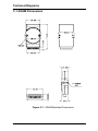
C.1 ADAM Dimensions ..............................................…................ C-2
C.2 Installation .............................................................….............. C-3
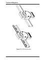
C.2.1 DIN-Rail Mounting ......................................................…...….............. C-3
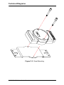
C.2.2 Panel Mounting .............................................................…….............. C-5
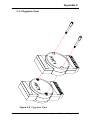
C.2.3 Piggyback Stack ....................................................….....…................. C-7
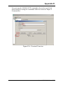
Appendix D Utility Software .................................…..................... D-1
D.1 ADAM-4000 Utility Software ......................…......................... D-2
Appendix E RS-485 Network .............................…........................ E-1
E.1 Basic Network Layout ................................…......................... E-3
E.2 Line Termination .........................................…........................ E-5
E.3 RS-485 Data Flow Control ..................................................... E-7
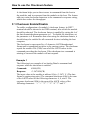
Appendix F How to use the Checksum feature ..........…............ F-1
F.1 Checksum Enable/Disable ......................................…............ F-2
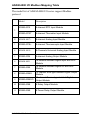
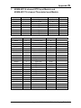
Appendix G ADAM-4000 I/O Modbus Mapping Table ....…......... G-1
Appendix H Changing Configuration to Modbus Protocol ....... H-1
Introduction
1.1 Overview
The ADAM Series is a set of intelligent sensor-to-computer interface
modules containing built-in microprocessor. They are remotely
controlled through a simple set of commands issued in ASCII format
and transmitted in RS-485 protocol. They provide signal conditioning,
isolation, ranging, A/D and D/A conversion, data comparison, and
digital communication functions. Some modules provide digital I/O
lines for controlling relays and TTL devices.
Software Configuration and Calibration
ADAM modules contain no pots or switches to set. By merely issuing a
command from the host computer, you can change an analog input
module to accept several ranges of voltage input, thermocouple input or
RTD input. All the module’s configuration parameters including I/O
address, speed, parity, HI and LO alarm, calibration parameters settings
may be set remotely. Remote configuration can be done by using either
the provided menu-based software or the command set’s configuration
and calibration commands.
By storing configuration and calibration parameters in a nonvolatile
EEPROM, modules are able to retain these parameters in case of power
failure.
Watchdog Timer
A watchdog timer supervisory function will automatically reset the
ADAM modules in the event of system failure. Maintenance is thus
simplified.
Power Requirements
Although the modules are designed for standard industrial unregulated
24 VDC power supply , they accept any power unit that supplies power
within the range of +10 to +30 VDC. The power supply ripple must be
limited to 5 V peak-to-peak, and the immediate ripple voltage should be
maintained between +10 and +30 VDC.
Connectivity and Programming
ADAM modules can connect to and communicate with all computers
and terminals. They use RS-485 transmission standards, and
communicate with ASCII format commands. The command set for
every module type consists of approximately ten different commands.
1-2 ADAM 4000 Series User’s Manual
Chapter 1
The command set for input modules is larger because it incorporates
alarm functions. All communications to and from the module are
performed in ASCII, which means that ADAM modules can be
programmed in virtually any high-level language.
RS-485 Network
The RS-485 network provides lower-noise sensor readings, as modules
can be placed much closer to the source. Up to 256 ADAM modules
may be connected to an RS-485 multi-drop network by using the
ADAM RS-485 repeater, extending the maximum communication
distance to 4,000 ft. The host computer is connected to the RS-485
network with one of its COM ports through the ADAM RS-232/RS-485
converter.
To boost the network’s throughput, the ADAM RS-485 repeaters use a
logical RTS signal to manage the repeater’s direction. Only two wires
are needed for the RS-485 network: DATA+ and DATA-. Inexpensive
shielded twisted pair wiring is employed.
Panel/DIN Rail mounting
Chapter 1 Introduction 1-3
Introduction
ADAM modules mount on any panel, on provided brackets, on DIN
rails or may be stacked together.
The RS-485 network, together with screw-terminal plug connectors,
allows for system expansion, reconfiguration and repair without
disturbing field wiring.
Protection against the environment
Hardened plastic packing forms the outer shell of every module. Since
all configuration is controlled by software, the module is not designed
to be opened. This greatly enhances resistance against corrosive
materials, moisture and vibration. ADAM modules’ low power
requirements help them to operate in temperatures from 0 to 70oC, and
in humidities from 0 to 95% (non-condensing). They’re built compactly
using automated SMT technology so you can pack them into watertight and explosion-proof industrial enclosures.
1.2 Applications
•
•
•
•
•
•
•
•
•
•
Remote data acquisition
Process monitoring
Industrial process control
Energy management
Supervisory control
Security systems
Laboratory automation
Building automation
Product testing
Direct digital control
1-4 ADAM 4000 Series User’s Manual
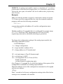
Installation Guideline
This chapter provides guidelines to what is needed to set up and install
an ADAM network. A quick hookup scheme is provided that lets you
configure modules before they are installed in a network.
To help you to connect ADAM modules with sensor inputs, several
wiring examples are provided. Finally, you will find at the end of this
chapter a programming example using the ADAM command set.
Be sure to carefully plan the layout and configuration of your network
before you start. Guidelines regarding layout are given in Appendix E:
RS-485 Network.
NOTICE: Except for the communication modules (ex. ADAM4520/4521/4522…etc.), which have on-board switches for their baud
rate setting; ADAM modules should not be opened. There is no need to
open the ADAM modules: all configurations are done remotely and
there are no user serviceable parts are inside. Opening the cover will
therefore void the warranty.
2.1 System Requirements to set up an ADAM network
The following list gives an overview of what is needed to setup, install
and configure an ADAM environment.
• ADAM modules
• A host computer, such as an IBM PC/AT compatible, that can
output ASCII characters with an RS-232C or RS-485 port.
• Power supply for the ADAM modules (+10 to +30 VDC )
• ADAM Series Utility software
• ADAM Isolated RS-232/RS-485 Converter (optional)
• ADAM Repeater (optional)
Host computer
Any computer or terminal that can output in ASCII format over either
RS-232 or RS-485 can be connected as the host computer. When only
RS-232 is available, an ADAM RS-232/RS-485 Converter is required
to transform the host signals to the correct RS-485 protocol. The
converter also provides opto-isolation and transformer-based isolation
to protect your equipment.
2-2 ADAM 4000 Series User’s Manual
Chapter 2
Power supply
For the ease of use in industrial environments the ADAM modules are
designed to accept industry standard +24 VDC unregulated power.
Operation is guaranteed when using any power supply between +10 and
+30 VDC . Power ripples must be limited to 5 V peak to peak while the
voltage in all cases must be maintained between +10 and +30 VDC . All
power supply specifications are referenced at module connector. When
modules are powered remotely, the effects of line voltage drops must be
considered.
All modules use on-board switching regulators to sustain good
efficiency over the 10-30 V input range, therefore we can assume that
the actual current draw is inversely proportional to the line voltage. The
following example shows how to calculate the required current that a
power supply should be able to provide.
Assume that a +24 VDC will be used to power five ADAM-4011 Analog
Input Modules. The distance from power supply to modules is not so
big that significant line voltage drop will occur. One ADAM-4011
module consumes a maximum of 1.2 Watts. The total required power
will equal 5 x 1.2 = 6 Watts. A power supply of +24 VDC should
therefore be able to supply a minimal current of 6 / 24 = 0.25 Amps.
Small systems may be powered by using wall-mounted modular power
supplies. Also when modules operate on long communication lines
(>500 feet) it is often more reliable to power the modules locally with
modular power supplies. These inexpensive units can easily be obtained
from any electronics retail store.
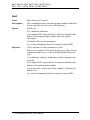
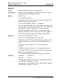
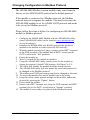
The power cables should be selected according to the number of
modules connected and the length of the power lines. When using a
network with long cables, we advise the use of thicker wire to limit the
line voltage drop. In addition to serious voltage drops, long voltage
lines can also cause interference with communication wires.
Chapter 2 installation Guideline 2-3
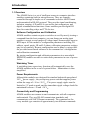
Installation Guideline
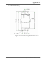
Figure 2-1 Power Supply Connections
We advise that the following standard colors (as indicated on the
modules) be used for power lines:
+Vs
(R)
Red
GND
(B)
Black
Communication Wiring
We recommend that shielded-twisted-pair cables that comply with the
EIA RS-485 standard be used with the ADAM network to reduce
interference. Only one set of twisted-pair cables is required to transmit
both Data and RTS signals. We advice that the following standard
colors (as indicated on the modules) be used for the communication
lines:
DATA+ (Y)
Yellow
DATA- (G)
Green
ADAM Utility Software
A menu-driven utility program is provided for ADAM module
configuration, monitoring and calibration. It also includes a terminal
emulation program that lets you easily communicate through the
ADAM command set. (See Appendix D, Utility Software)
2-4 ADAM 4000 Series User’s Manual
Chapter 2
ADAM Communication Speed
In ADAM series, the baudrate can be configured from 1200 bps to 38.4
Kbps. And the baudrate of all modules in an RS-485 network must be
the same.
ADAM Isolated RS-232/RS485 Converter (optional)
When the host computer or terminal has only a RS-232 port, an ADAM
Isolated RS-232/RS-485 Converter, connected to the host’s RS-232
port, is required. Since this module is not addressable by the host, the
baud rate must be set using a switch inside the module. The factory
default setting is 9600 baud.
ADAM Repeater (optional)
When communication lines exceed 4000 ft (1200 meter) or the number
of ADAM modules connected is more than 32, a repeater should be
connected to expand the first segment. Up to 8 Repeater modules can
be connected allowing connection of up to 255 ADAM modules. As
with the Converter module, the Repeater module is not addressable by
the host and the baud rate must be set by changing the switch inside the
module. The factory default setting is 9600 baud.
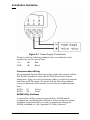
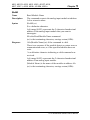
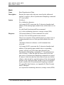
2.2 Basic configuration and hook-up
Before placing a module in an existing network, the module should be
configured. Though all modules are initially configured at the factory, it
is recommended to check that the baud rate is set correctly.
Default Factory Settings
Baud rate: 9600 Bit/sec.
Address: 01 (hexadecimal)
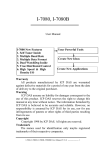
The basic hook-up for module configuration is shown below.
Chapter 2 installation Guideline 2-5
Installation Guideline
ADAM-4520 RS-232/RS-485 Converter
DATA+
DATA+
RS-485
TXD (3)
DATA-
DATA-
RXD (2)
HOST PC
RS-232
ADAM
I/O
Module
RTS (7)
GND (5)
+Vs
GND
+Vs
GND
POWER
+10~+30 VDC
()=pin number on EIA-232-D
connector (RS-232)
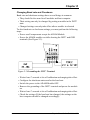
Figure 2-2 Basic Hook-up of ADAM Module to Host Switches
The following items are required to configure a module: an ADAM
converter module, a personal computer with RS-232 port (baud rate set
to 9600) and the ADAM utility software.
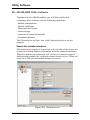
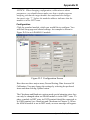
Configuration with the ADAM Utility Software
The easiest way to configure the ADAM module is by using the ADAM
utility software: an easy-to-use menu-structured program will guide you
through every step of the configuration. (See Appendix D, Utility
Software)
Changing the protocol from ADAM ASCII to Modbus
Some ADAM-4000 modules support both ADAM ASCII protocol and
Modbus protocol . The factory default setting of these modules is
ADAM ASCII protocol. If you would like to configure the modules to
Modbus protocol, please refer to Appendix H which describes how to
change the protocol in ADAM utility.
Configuration with the ADAM command set
ADAM modules can also be configured by issuing direct commands
from within a terminal emulation program that is part of the ADAM
utility software.
The following example guides you through the setup of an analog input
module. Assume that an ADAM-4011 Analog Input module still has its
default settings (baud rate 9600 and address 01h). Before the module is
reconfigured, it is first requested to send its default settings.
2-6 ADAM 4000 Series User’s Manual
Chapter 2
NOTICE: An analog input module requires a maximum of 7 seconds to
perform auto calibration and ranging after it is rebooted or powered on.
During this time span, the module can not be addressed to perform any
other actions.
Example:
Make sure that the module is properly connected as shown in section
2-5. Power up all the connected devices, start the terminal emulation
program, and issue the following command:
$012(cr)
requests that module with address 01 send its configuration status
!01050600
Module at address 01 responds that it is configured for an input range
of +/-2.5 V, baud rate 9600, integration time of 50 ms (60 Hz),
engineering units and no checksum checking or generation.
To change the configuration setting of the analog input module, the
following command is issued:
%01070F0600(cr)
% = change configuration
01 = target module at address 00 to:
07 = change address to 07 hexadecimal
0F = set input range to Type K thermocouple
06 = set baud rate to 9600
00 = set integration time to 50 ms (60 Hz)
disable checksum
set data format to engineering units
(See Chapter 4, Command Set for a full description of the syntax of the
configuration command for an analog input module)
When the module received the configuration command it will respond
with its new address:
!07(cr)
Wait 7 seconds to let the new configuration settings take effect before
issuing a new command to the module.
Chapter 2 installation Guideline 2-7
Installation Guideline
NOTICE: All reconfiguration except changing of baud rate and
checksum values can be done dynamically, i.e. the modules need not to
be reset. When changing the baud rate or checksum, these changes
should be made for all connected devices. After reconfiguration, all
modules should be powered down and powered up to force a reboot
and let the changes take effect. See the next page for a strategy for
changing baud rate and or checksum for an entire network.
2.3 Baud rate and Checksum
Adam modules contain EEPROMs to store configuration information
and calibration constants. The EEPROM replaces the usual array of
switches and pots required to specify baud rate, input/output range etc.
All of the ADAM modules can be configured remotely through their
communication ports, without having to physically alter pot or switch
settings.
Since there is no visual indication of a module’s configuration status, it
is impossible just by looking at it what the baud rate, address and other
settings are. It might not be possible to establish communications with a
module whose baud rate and address are unknown. To overcome this
problem, every module has an input terminal labeled INIT*. By booting
the module while connecting the INIT* terminal with the module’s
GND terminal, the modules configuration is forced into a known state.
This state is called the INIT* state.
INIT* state defaults:
Baud rate: 9600
Address: 00h
Checksum: disabled
Forcing the module in the INIT* state does not change any parameters
in the module’s EEPROM. When the module is in the INIT* state with
its INIT* and GND terminals shorted, all configuration settings can be
changed and the module will respond to all other commands normally.
2-8 ADAM 4000 Series User’s Manual
Chapter 2
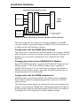
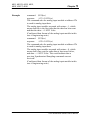
Changing Baud rate and Checksum
Baud rate and checksum settings have several things in common:
• They should be the same for all modules and host computer.
• Their setting can only be changed by putting a module in the INIT*
state.
• Changed settings can only take effect after a module is rebooted
To alter baud rate or checksum settings you must perform the following
steps:
• Power on all components except the ADAM Module.
• Power the ADAM module on while shorting the INIT* and GND
terminals (See Figure 2-3).
Figure 2-3 Grounding the INIT* Terminal
•
•
•
•
Wait at least 7 seconds to let self calibration and ranging take effect.
Configure the checksum status and/or the baud rate.
Switch the power to the ADAM Module OFF.
Remove the grounding of the INIT* terminal and power the module
on.
• Wait at least 7 seconds to let self calibration and ranging take effect.
• Check the settings (If the baud rate has changed, the settings on the
host computer should be changed accordingly).
Chapter 2 installation Guideline 2-9
Installation Guideline
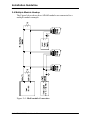
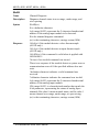
2.4 Multiple Module Hookup
The Figure below shows how ADAM modules are connected in a
multiple module example:
Figure 2-4 Multi-module Connection
2-10 ADAM 4000 Series User’s Manual
Chapter 2
2.5 Programming Example
The following example is a simple program written in Visual Basic 6.0
that demonstrates how to get temperature reading from ADAM-4011
module, which is addressed at 01H.
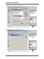
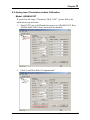
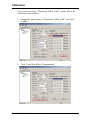
Step 1. Using ADAM Utility to check the settings of “Address = 01H”,
“Baud rate = 9600” and “Checksum = Disabled” as following.
Step 2. Run VB 6.0 and add a control via “Project\Component”.
Chapter 2 installation Guideline 2-11
Installation Guideline
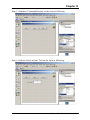
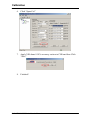
Step 3. Select “Microsoft Comm Control”
Step 4. Add the Comm Control on the form.
2-12 ADAM 4000 Series User’s Manual
Chapter 2
Step 5. Add three Command Buttons on the form as following
Step 6. Add one Label and one Text on the form as following.
Chapter 2 installation Guideline 2-13
Installation Guideline
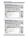
Step 7. Click OPEN Button and type following codes. The source codes are
listed at the end of this section.
Step 8. Click SEND Button and type following codes. The source codes are
listed at the end of this section.
2-14 ADAM 4000 Series User’s Manual
Chapter 2
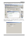
Step 9. Click CLOSE Button and type following codes. The source codes are
listed at the end of this section.
Step 10. Run the Project → Click OPEN to open COM1 → Click SEND to
send the Get Temperature Reading Command. Now you will find the reading
is displayed as following format.
Chapter 2 installation Guideline 2-15
Installation Guideline
Program Source Codes:
OPEN Command Button:
Private Sub Command1_Click()
' Buffer to hold input string
Dim Instring As String
' Use COM1.
MSComm1.CommPort = 1
' 9600 baud, no parity, 8 data, and 1 stop bit.
MSComm1.Settings = "9600,N,8,1"
' Tell the control to read entire buffer when Input
' is used.
MSComm1.InputLen = 0
' Open the port.
MSComm1.PortOpen = True
End Sub
SEND Command Button:
Private Sub Command2_Click()
' Send Get AI command to ADAM-4011 Module at address 01H.
MSComm1.Output = "#01" & Chr$(13)
' Wait for data to come back to the serial port.
Do
DoEvents
Buffer$ = Buffer$ & MSComm1.Input
Loop Until InStr(Buffer$, vbCr)
' Read the response till the carriage return character.
Text1.Text = Buffer$
' Display the reading.
End Sub
CLOSE Command Button
Private Sub Command3_Click()
' Close the serial port.
MSComm1.PortOpen = False
End Sub
2-16 ADAM 4000 Series User’s Manual
I/O Modules
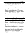
3.0 The common specification of ADAM-4000 I/Oseries
Communication:
z
RS-485 (2-wire) to host
z
Speeds: 1200, 2400, 4800, 9600, 19200, 38400, 57600, 115200 bps
(ADAM-4080, ADAM-4080D only support up to 38400 bps)
z
Max. communication distance: 4000 feet (1.2 km)
z
Power and communication LED indicator
z
ASCII command/response protocol
z
Communication error checking with checksum
z
Asynchronous data format: 1 start bit, 8 data bits, 1 stop bit, no
parity (N, 8, 1)
z
Up to 256 multidrop modules per serial port
z
Online module insertion and removal
z
Transient suppression on RS-485 communication lines
Power Requirements
z
Unregulated +10 ~ +30 VDC
z
Protected against power reversal
Mechanical
z
Case
z
Plug-in screw
terminal block
ABS with captive mounting hardware
Accepts 0.5 mm2 to 2.5 mm2,
#14 to #22 AWG
Environment
z
Operating Temperature
z
EMI
z
Storage Temperature
z
Humidity
3-2 ADAM 4000 Series User’s Manual
-10 ~ 70° C (14 ~ 158° F)
Meets FCC Class A or CE
-25 ~ 85° C (-13 ~ 185° F)
5 ~ 95%, non-condensing
Chapter 3
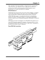
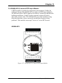
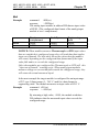
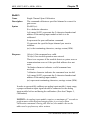
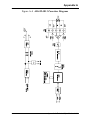
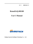
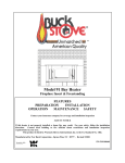
3.4 ADAM-4015 6-channel RTD Input Module
A RTD module is popular for temperature measurement. Unlike the
traditional design, the ADAM-4015 provides six RTD input channels
for different types of RTD signal as an effective solution in industrial &
building automation. Usually, broken external wiring will lead to
inaccurate current value. The ADAM-4015 provides a broken wiring
detecting function so users can easily troubleshoot broken wiring
problems. This module can accept 2 wires or 3 wires RTD sensor.
14 RTD0+
RTD0(R) +Vs
- 150蚓
- 100蚓
- 200蚓
- 400蚓
- 200蚓
- 160蚓
- 120蚓
- 100蚓
- 100蚓
(G)DATA-
N/A
RANGE
-50蚓
0蚓
0蚓
0蚓
-200蚓
-40蚓
-30蚓
-80蚓
0蚓
(Y) DATA+
INIT*
N/A
Pt 100
Pt 1000
BALCO 500
Ni
Ni
RTD5-
TYPE
RTD5+
CODE
(IEC/JIS) 30/35
(IEC/JIS) 30/35
(IEC/JIS) 30/35
(IEC/JIS) 30/35
(IEC/JIS) 30/35
40
41
42
43
(B) GND13
RTD1-
COM 0
COM 1
RTD1+
RTD2-
RTD2+
COM 2
RTD3+
GND
RTD3RTD4+
COM 5
RTD4-
COM 4 1
26
COM 3
ADAM-4015
Figure 3-17: ADAM-4015 6-channel RTD Input Module
Chapter 3 I/O Modules 3-17
I/O Modules
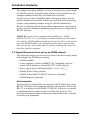
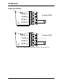
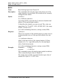
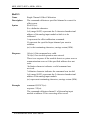
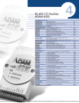
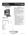
Application Wiring
RTD 1+
COM 0
2-wire RTD
RTD 014
RTD 0+
RTD 1+
3-wire RTD
COM 0
RTD 014
RTD 0+
Figure 3-18: ADAM-4015 RTD Input Module Wiring Diagram
3-18 ADAM 4000 Series User’s Manual
Chapter 3
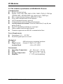
Technical specification of ADAM-4015
Channel
6
Input Type
Pt100, Pt1000, BALCO500, Ni
Pt100: -50 to 150° C
0 to 100° C
0 to 200° C
0 to 400° C
-200 to 200° C
Pt1000: -40 to 160° C
Input type and
temperature range
BALCO500: -30 to 120° C
Ni 50 RTD: -80 to 100° C
Ni 508 RTD: 0 to 100° C
Isolation Voltage
3000 VDC
Sampling Rate
12 sample/sec (total)
Input Impedance
10 MΩ
Accuracy
+/- 0.1% or better
Power Consumption
1W
I/O Connector Type
13- pin plug-terminal
Table 3-1: Technical specification of ADAM-4015
Chapter 3 I/O Modules 3-19
Command Set
4.1 Introduction
To avoid communication conflicts when several devices try to send data
at the same time, all actions are instigated by the host computer. The
basic form is a command/response protocol with the host initiating the
sequence.
When modules are not transmitting they are in listen mode. The host
issues a command to a module with a specified address and waits a
certain amount of time for the module to respond. If no response arrives,
a timeout aborts the sequence and returns control to the host.
Changing ADAM’s configuration might require the module to perform
auto calibration before changes can take effect. Especially when
changing the range, the module has to perform all stages of auto
calibration that it also performs when booted. When this process is
under way, the module does not respond to any other commands. The
command set includes the exact delays that might occur when modules
are reconfigured.
4.2 Syntax
[delimiter character][address][command][data][checksum] [carriage
return]
Every command begins with a delimiter character. There are four valid
characters: a dollar sign $, a pound sign #, a percentage sign % and an
at sign @.
The delimiter character is followed by a two-character address
(hexadecimal) that specifies the target module. The actual two character
command follows the address. Depending on the command, an optional
data segment follows the command string. An optional two character
checksum may be appended to the total string. Every commands is
terminated by a carriage return (cr).
ALL COMMANDS SHOULD BE ISSUED IN UPPERCASE
CHARACTERS!
4-2 ADAM 4000 Series User’s Manual
Chapter
4
Before the command set, we provide the I/O module commands search
table to help you find the commands you wish to use. The command set
is divided into the following three types:
• Analog Input Module commands
• Analog Output Module commands
• Digital I/O, Relay Output and Counter/Frequency Module
commands
Every type starts with a command summary of the particular type of
module and they are described on Chapter 5, 6 & 7 , followed by
datasheets that give detailed information about individual commands.
Although commands in different subsections sometimes share the same
format, the effect they have on a certain module can be completely
different than they have on another. For example, the configuration
command: %AANNTTCCFF affects analog input modules and analog
output modules differently. Therefore, the full command set for every
module is listed.
Chapter 4 Command Set 4-3
Chapter
4
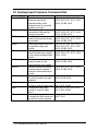
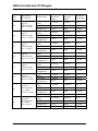
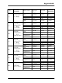
ADAM-4015/ADAM-4015T Command Table
Command Syntax
Command Name
Command Description
%AANNTTCCFF
Configuration
#AAN
Read Analog Input
from Channel N
#AA
Analog Data In
$AA0Ci
Single Channel
Span Calibration
Sets the address, baud rate, data format,
checksum status, and/or integration time for a
specified analog input module
Returns the input value from a specified channel of
analog input module in the currently configured
data format
Returns the input value from a specified analog
input module in the currently configured data format
Calibrates a specified channel to correct for gain
errors
$AA1Ci
Single Channel
Offset Calibration
Calibrates a specified channel to correct for offset
errors
5-28
$AA2
Configuration Status
Returns the configuration parameters for the
specified analog input module
5-10
#**
Synchronized
Sampling
Orders all analog input modules to sample their
input values and store them in special registers
5-21
$AA4
Read Synchronized
Data
Enable/Disable
Channels for
Multiplexing
Read Channel
Status
Returns the value that was stored in the specified
module's register after the #** command
Enable or disable the individual channels in an
analog module
5-22
Get the enable/disable status of all channels in an
analog module
5-18
$AAB
Channel Diagnose
Diagnose channel status in over range, under
range, and wire opening
5-24
$AA7CiRrr
Single Channel
Range Configuration
Configure the input type and range of the specified
channel in an analog input module
5-29
$AA8Ci
Read Single
Channel Range
Configuration
Watchdog Timer
Setting
Read Watchdog
Timer Setting
Get the input type and range of the specified
channel in an analog input module
5-30
Set WDT communication cycle
5-31
Read the setting of WDT communication cycle
5-32
$AAS0
Internal Calibration
Internal self-calibration for offset and gain errors
5-33
$AAS1
Reload default
calibrating
parameter
Read Firmware
Version
Reload factory default calibrating parameter to
overwrite current calibrating parameter
5-34
Return the firmware version code from the
specified analog input module
5-12
Read Module Name
Return the module name from the specified analog
input module
5-13
$AA5VV
$AA6
$AAXnnnn
$AAY
$AAF
$AAM
Page
No.
5-4
5-16
5-14
5-27
5-17
Chapter 4 Command Set 4-11
Analog Input Module Command Set
5
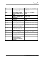
5.1 Analog Input Common Command Set
Command Syntax
%AANNTTCCFF
$AA2
$AAF
$AAM
#AA
#AAN
#AA5VV
$AA6
$AA0
$AA1
#**
Description
Sets the address, input range,
baud rate, data format,
checksum status, and/or
integration time for a specified
analog input module
Returns the configuration
parameters for the specified
analog input module
Returns the firmware version
code from the specified analog
input module
Returns the module name from
the specified analog input
module
Returns the input value from a
specified analog input moudule
in the currently configured data
format
Returns the input value from
channel number n of the
specified analog input module
Enables/disables multiplexing
simultaneously for separate
channels of the specified input
module
Ask the specified input module
to return the status of all eight
channels
Calibrate the analog input
module to correct for gain errors
Calibrate the analog input
module to correct for offset
errors.
Orders all analog input modules
to sample their input values and
store them in special registers
5-2 ADAM 4000 Series User’s Manual
I/O Module
4011, 4011D, 4012, 4013, 4015,
4015T, 4016, 4017, 4017+, 4018,
4018+, 4018M, 4019+
4011, 4011D, 4012, 4013, 4015,
4015T, 4016, 4017, 4017+, 4018,
4018+, 4018M, 4019+
4011, 4011D, 4012, 4013, 4015,
4015T, 4016, 4017, 4017+, 4018,
4018+, 4018M, 4019+
4011, 4011D, 4012, 4013, 4015,
4015T, 4016, 4017, 4017+, 4018,
4018+, 4018M, 4019+
4011, 4011D, 4012, 4013, 4015,
4015T, 4016, 4017, 4017+, 4018,
4018+, 4019+
4015, 4015T, 4017, 4017+, 4018,
4018+, 4018M, 4019+
4015, 4015T, 4017, 4017+, 4018,
4018+, 4018M, 4019+
4015, 4015T, 4017, 4017+, 4018+,
4018, 4018M, 4019+
4011, 4011D, 4012, 4013, 4016,
4017, 4018, 4018M
4011, 4011D, 4012, 4013, 4016,
4017, 4018, 4018M
4011, 4011D, 4012, 4013, 4015,
4015T, 4016
Chapter
Command Syntax
$AA4
$AAB
$AA3
$AA9
$AA0Ci
$AA1Ci
$AA7CiRrr
$AA8Ci
$AAXnnnn
$AAY
$AAS0
$AAS1
Command Description
Returns the value that was
stored in the specified module's
register after the #** command
Ask the module to respond
whether the wiring is open or
closed
Returns the value of the CJC
sensor for a specified analog
input module
Calibrates the CJC sensor for
offset errors
Calibrates a specified channel
to correct for gain errors
Calibrates a specified channel
to correct for offset errors
Configure the input type and
range of the specified channel
in an analog input module
Get the input type and range of
the specified channel in an
analog input module
Set WDT communication cycle
Read the setting of WDT
communication cycle
Internal self-calibration for offset
and gain errors
Reload factory default
calibrating parameter to
overwrite current calibrating
parameter
5
I/O Module
4011, 4011D, 4012, 4013, 4015,
4015T, 4016
4011D, 4015, 4015T, 4018+,
4019+
4011, 4011D, 4018, 4018+,
4018M, 4019+
4011, 4011D, 4018, 4018+, 4018M
4019+
4015, 4015T, 4017+, 4018+, 4019+
4015, 4015T, 4017+, 4018+, 4019+
4015, 4015T, 4017+, 4018+, 4019+
4015, 4015T, 4017+, 4018+, 4019+
4015, 4015T, 4018+,4019+
4015, 4015T, 4018+, 4019+
4015, 4015T
4015, 4015T
5-3 ADAM 4000 Series User’s Manual
4011, 4011D, 4012, 4013, 4015, 4015T, 4016,
4017, 4017+, 4018, 4018+, 4018M, 4019+
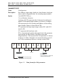
%AANNTTCCFF
Name
Description
Syntax
7
Configuration
Sets address, input range, baud rate, data format, checksum
status, and/or integration time for an analog input module.
%AANNTTCCFF(cr)
% is a delimiter character.
AA(range 00-FF) represents the 2-character hexadecimal
address of the analog input module you want to configure.
NN represents the new hexadecimal address of the analog
input module. Range is from 00h to FFh.
TT represents the type (input range) code.(4015 and 4019
must be 00)
CC represents the baud rate code.
FF is a hexadecimal number that equals the 8-bit parameter
representing the data format, checksum status and
integration time. The layout of the 8-bit parameter is shown
in figure 4-1. Bits 2 through 5 are not used and are set to 0.
(cr) is the terminating character, carriage return (0Dh)
6
5
4
Checksum status
0: Disabled
1: Enabled
3
not used
Integration time
0: 50 ms (Operation under 60 Hz power)
1: 60 ms (Operation under 50 Hz power)
2
1
Data Format
00: Engineering units
01: % of FSR
10: two's complement of hexadecimal
11: Ohms (for 4013 and 4015)
Figure 5-1 Data format for 8-bit parameter
5-4 ADAM 4000 Series User’s Manual
0
4011, 4011D, 4012, 4013, 4015, 4015T, 4016,
4017, 4017+, 4018, 4018+, 4018M, 4019+
Chapter
5
%AANNTTCCFF
Response
Example
!AA(cr) if the command is valid.
?AA(cr) if an invalid parameter was entered or if the INIT*
terminal was not grounded when attempting to change baud
rate or checksum settings.
There is no response if the module detects a syntax error or
communication error or if the specified address does not
exist.
! delimiter character indicates a valid command was
received.
? delimiter character indicates the command was invalid
AA (range 00-FF) represents the 2-character hexadecimal
address of an analog input module.
(cr) is the terminating character, carriage return (0Dh)
command:
%2324050600(cr)
response:
!24(cr)
The ADAM-4011 module with address 23h is configured to
a new address of 24h, an input range ±2.5 V, baud rate
9600, integration time 50 ms (60 Hz), engineering units
data format and no checksum checking or generation.
The response indicates that the command was received.
Wait 7 seconds to let the new configuration settings take
effect before issuing a new command to the module.
NOTICE: Only ADAM-4011, ADAM-4011D, ADAM-4012,
ADAM-4013,ADAM-4016 and ADAM-4018+ support “% of FSR” and
“two’s complement of hexadecimal” Data Format.
NOTICE: An analog input module requires a maximum of 7 seconds to
perform auto calibration and ranging after it is reconfigured. During
this time span, the module cannot be addressed to perform any other
actions.
NOTICE: All configuration parameters can be changed dynamically,
except checksum and baud rate parameters. They can only be altered
when the INIT* terminal is grounded. (Refer to Baud rate and
Checksum configuration in Chapter 2, for the correct procedure)
5-5 ADAM 4000 Series User’s Manual
4011, 4011D, 4012, 4013, 4015, 4015T, 4016,
4017, 4017+, 4018, 4018+, 4018M, 4019+
Table 5-1 Input Range Codes (Type Code)
Input Range Code (Hex)
00
01
02
03
04
05
06
0E
0F
10
11
12
13
14
Input Range for
4011,4011D,4018,4018+(Thermocouple
and ± 20 mA only), 4018M
± 15 mV
± 50 mV
± 100 mV
± 500 mV
±1V
± 2.5 V
± 20 mA
Type J Thermocouple 00 to 7600 C
Type K Thermocouple 00 to 13700 C
Type T Thermocouple -1000 to 4000 C
Type E Thermocouple 00 to 10000 C
Type R Thermocouple 5000 to 17500 C
Type S Thermocouple 5000 to 17500 C
Type B Thermocouple 5000 to 18000 C
Input Range Code(Hex)
Input Range for 4012,4017,4017+
08
± 10 V
09
±5V
0A
±1V
0B
± 500 mV
0C
± 150 mV
0D
± 20 mA1
Notice: The input range requires the usage of a 125 Ω current
conversion resistor
Input Rage Code (Hex)
00
01
02
03
06
Input Range for 4016
±15 mV
±50 mV
±100 mV
±500 mV
±20 mA
5-6 ADAM 4000 Series User’s Manual
4011, 4011D, 4012, 4013, 4015, 4015T, 4016,
4017, 4017+, 4018, 4018+, 4018M, 4019+
Input Range Code (Hex)
20
21
22
23
24
25
26
27
28
29
Chapter
5
Input Range for 4013
Platinum, -100o to 100oC, a=0.00385
Platinum, 0o to 100oC, a=0.00385
Platinum, 0o to 200oC, a=0.00385
Platinum, 0o to 600oC, a=0.00385
Platinum, -100o to 100oC, a=0.003916
Platinum, 0o to 100oC, a=0.003916
Platinum, 0o to 200oC, a=0.003916
Platinum, 0o to 600oC, a=0.003916
Nickel, -80o to 100oC
Nickel, 0o to 100oC
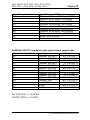
ADAM-4015/4015T command codes against Input ranges table
Command Code (Hex)
20
21
22
23
24
25
26
27
28
29
2A
2B
2C
2D
Input Type
Platinum 100 (IEC)
Platinum 100 (IEC)
Platinum 100 (IEC)
Platinum 100 (IEC)
Platinum 100 (IEC)
Platinum 100 (JIS)
Platinum 100 (JIS)
Platinum 100 (JIS)
Platinum 100 (JIS)
Platinum 100 (JIS)
Platinum 1000
BALCO 500
Ni 604
Ni 604
Input Range
-50° C to 150° C
0° C to 100° C
0° C to 200° C
0° C to 400° C
-200° C to 200° C
-50° C to 150° C
0° C to 100° C
0° C to 200° C
0° C to 400° C
-200° C to 200° C
-40° C to 160° C
-30° C to 120° C
-80° C to 100° C
0° C to 100° C
IEC RTD 100O, α = 0.00385
JIS RTD 100O, α = 0.00391
5-7 ADAM 4000 Series User’s Manual
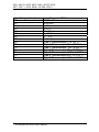
4011, 4011D, 4012, 4013, 4015, 4015T, 4016,
4017, 4017+, 4018, 4018+, 4018M, 4019+
Input Range Code (Hex)
02
03
04
05
07
08
09
0D
0E
0F
10
11
12
13
14
Input Range for 4019+
± 100 mV
± 500 mV
±1V
± 2.5 V
+4~20mA
± 10 V
± 5V
± 20 mA1
Type J Thermocouple 00 to 7600 C
Type K Thermocouple 00 to 13700 C
Type T Thermocouple -1000 to 4000 C
Type E Thermocouple 00 to 10000 C
Type R Thermocouple 5000 to 17500 C
Type S Thermocouple 5000 to 17500 C
Type B Thermocouple 5000 to 18000 C
5-8 ADAM 4000 Series User’s Manual
4011, 4011D, 4012, 4013, 4015, 4015T, 4016,
4017, 4017+, 4018, 4018+, 4018M, 4019+
Chapter
5
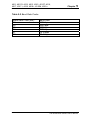
Table 5-2 Baud Rate Codes
Baud Rate Code (hex)
03
04
05
06
07
08
Baud Rate
1200 bps
2400 bps
4800 bps
9600 bps
19.2 kbps
38.4 kbps
5-9 ADAM 4000 Series User’s Manual
4011, 4011D, 4012, 4013, 4015, 4015T, 4016,
4017, 4017+, 4018, 4018+, 4018M, 4019+
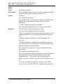
$AA2
Name
Description
Syntax
Response
Configuration Status
The command requests the return of the configuration data
from the analog input module at address AA.
$AA2(cr)
$ is a delimiter character.
AA (range 00-FF) represents the 2-character hexadecimal
address of the analog input module that you want to
interrogate.
2 is the Configuration Status command.
(cr) is the terminating character, carriage return (0Dh).
!AATTCCFF(cr) if the command is valid.
?AA(cr)if an invalid operation was entered.
There is no response if the module detects a syntax error or
communication error or if the specified address does not
exist.
! delimiter character indicates a valid command was
received.
? delimiter character indicates the command was invalid.
AA (range 00-FF) represents the 2-character hexadecimal
address of an analog input module.
TT represents the type code. Type code determines the
input range.
CC represents the baud rate code.
FF is a hexadecimal number that equals the 8-bit parameter
that represents the data format, checksum status and
integration time . The layout of the 8-bit parameter is
shown in figure 4-1. Bits 2 to 5 are not used, and are set to
0.
(cr) is the terminating character, carriage return (0Dh).
(Also see the %AANNTTCCFF configuration command)
5-10 ADAM 4000 Series User’s Manual
4011, 4011D, 4012, 4013, 4015, 4015T, 4016,
4017, 4017+, 4018, 4018+, 4018M, 4019+
Chapter
5
$AA2
Example
command:
$452(cr)
response:
!45050600(cr)
The command asks the analog input module at address 45h
to send its configuration data.
The analog input module at address 45h responds with an input range of 2.5
volts, a baud rate of 9600 bps, an integration time of 50 ms (60 Hz),
engineering units are the currently configured data format, and no checksum
function or checksum generation.
5-11 ADAM 4000 Series User’s Manual
4011, 4011D, 4012, 4013, 4015, 4015T, 4016,
4017, 4017+, 4018, 4018+, 4018M, 4019+
$AAF
Name
Description
Syntax
Response
Read Firmware Version
The command requests the analog input module at address
AA to return the version code of its firmware
$AAF (cr)
$ is a delimiter character.
AA (range 00-FF) represents the 2-character hexadecimal
address of the analog input module that you want to
interrogate.
F identifies the version command.
(cr) is the terminating character, carriage return (ODh)
!AA(Version)(cr) if the command is valid.
There is no response if the module detects a syntax error or
communication error, or if the specified address does not
exist.
! is a delimiter character indicating a valid command was
received.
AA (range 00-FF) represents the 2-character hexadecimal
address of an analog input module.
(Version) is the version code of the module’s firmware at
address AA.
(cr) is the terminating character, carriage return (ODh).
5-12 ADAM 4000 Series User’s Manual
4011, 4011D, 4012, 4013, 4015, 4015T, 4016,
4017, 4017+, 4018, 4018+, 4018M, 4019+
Chapter
5
$AAM
Name
Description
Syntax
Response
Read Module Name
The command requests the analog input module at address
AA to return its name
$AAM (cr)
$ is a delimiter character.
AA (range 00-FF) represents the 2-character hexadecimal
address of the analog input module that you want to
interrogate.
M is the Read Module Name command.
(cr) is the terminating character, carriage return (ODh)
!AA(Module Name)(cr) if the command is valid.
There is no response if the module detects a syntax error or
communication error, or if the specified address does not
exist.
! is a delimiter character indicating a valid command was
received.
AA (range 00-FF) represents the 2-character hexadecimal
address of an analog input module.
(Module Name) is the name of the module at address AA.
(cr) is the terminating character, carriage return (ODh).
5-13 ADAM 4000 Series User’s Manual
4011, 4011D, 4012, 4013, 4015, 4015T, 4016,
4017, 4017+, 4018, 4018+,4019+
#AA
Name
Description
Syntax
Response
Example
Example
Analog Data In
The command will return the input value from a specified
(AA) module in the currently configured data format.
#AA(cr)
# is a delimiter character.
AA (range 00-FF) represents the 2-character hexadecimal
address of an analog input module.
(cr) is the terminating character, carriage return (0Dh).
>(data)(cr)
There is no response if the module detects a syntax error or
communication error or if the specified address does not
exist.
> is a delimiter character.
(data) is the input value in the configured data format of the
interrogated module. (For data formats, see Appendix B).
(cr) is the terminating character, carriage return (0Dh).
command: #33(cr)
response: >+5.8222(cr)
The command interrogates the analog input module at
address 33h for its input value.
The analog input module responds with +5.8222 volts.
(The configured data format of the analog input module in
this case is engineering units.)
command: #21(cr)
response: +7.2111+7.2567+7.3125+7.1000
+7.4712+7.2555+7.1234+7.5678 (cr)
The command interrogates the analog input module at
address 21h for its input values of all channels.
The analog input module responds with channels from 0 to
7 with +7.2111 volts, +7.2567 volts, +7.3125 volts,
+7.1000 volts, +7.4712 volts, +7.2555 volts, +7.1234 volts
and +7.5678 volts.
5-14 ADAM 4000 Series User’s Manual
4011, 4011D, 4012, 4013, 4015, 4015T, 4016,
4017, 4017+, 4018, 4018+, 4019+
Chapter
5
#AA
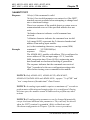
Example
under
over
command:
#DE(cr)
response:
>FF5D(cr)
The analog input module at address DEh has an input value
of FF5D. (The configured data format of the analog input
module is two’s complement)
Two’s
complement
0000
FFFF
% of Span
-0000
+9999
Engineering
units
-0000
+9999
NOTICE: When modules measure Thermocouple or RTD input values
that are outside their configured range they will send data that implies
input out of bounds. The next table shows the values that the modules
will return, depending on the configured data format and if the input
value falls under or exceeds the configured range.
Only when modules are configured for Thermocouple or RTD will this
“input out of bounds” warning occur. When analog input modules
measure voltage or current that falls outside the configured range, they
will return the actual measured input!
In the next example the target module is configured for an input range
of T/C type J (Input range: 0 - 760° C) and for a data format in
engineering units. The module measures an input value of 820° C.
Example
command: #D1(cr)
response: >+9999(cr)
By returning a high value, +9999, the module at address
D1h indicates that the measured input value exceeds the
configured range.
5-15 ADAM 4000 Series User’s Manual
4015, 4015T, 4017, 4017+, 4018,
4018+, 4018M, 4019+
#AAN
Name
Description
Syntax
Response
Example
Read Analog Input from Channel N
The command will return the input value from one of the
eight channels of a specified (AA) module in the currently
configured data format.
#AAN(cr)
# is a delimiter character.
AA (range 00-FF) represents the 2-character hexadecimal
address of the analog input module.
N identifies the channel you want to read. The value can
range from 0 to 7 for 4017, 4018, 4018M, 4019. (the range
of 4015 is from 0 to 5)
(cr) is the terminating character, carriage return (0Dh).
>(data)(cr)
There is no response if the module detects a syntax error or
communication error or if the specified address does not
exist.
> is a delimiter character.
(data) is the input value of the channel number N. Data
consists of a + or - sign followed by five decimal digits
with a fixed decimal point.
(cr) is the terminating character, carriage return (0Dh).
command:
#120(cr)
response:
>+1.4567(cr)
The command requests the analog input module at address
12h to return the input value of channel 0.
The analog input module responds that the input value of
channel 0 is equal to +1.4567 volts.
5-16 ADAM 4000 Series User’s Manual
4015, 4015T, 4017, 4017+, 4018,
4018+, 4018M, 4019+
Chapter
5
$AA5VV
Name
Description
Syntax
Response
Example
Enable/disable channels for multiplexing
Enables/disables multiplexing simultaneously for seperate
channels of a specified input module
$AA5VV(cr)
$ is a delimiter character.
AA (range 00-FF) represents the 2-character hexadecimal
address of analog input module.
5 is the enable/disable channels command.
VV are two hexidecimal values. The values are interpreted
by the module as two binary words (4-bit). The first word
represents the status of channel 4-7, the second word
represents the status of channel 0-3. Value 0 means the
channel is disabled, value 1 means the channel is enabled.
(cr) is the terminating character, carriage return (0Dh).
!AA(cr) if the command is valid.
?AA(cr)if an invalid operation was entered.
There is no response if the module detects a syntax error or
communication error or if the specified address does not
exist.
! delimiter character indicates a valid command was
received.
? delimiter character indicates the command was invalid.
AA (range 00-FF) represents the 2-character hexadecimal
address of an analog input module.
(cr) is the terminating character, carriage return (0Dh).
command:
$00581(cr)
response:
!00(cr)
Hexadecimal 8 equals binary 1000, which enables channel
7 and disables channels 4, 5, and 6.
Hexadecimal 1 equals binary 0001, which enables channel
0 and disables channel 1,2, and 3.
5-17 ADAM 4000 Series User’s Manual
4015, 4015T, 4017, 4017+, 4018,
4018+, 4018M, 4019+
$AA6
Name
Description
Syntax
Response
Example
Read Channel Status
Asks a specified input module to return the status of all
channels
$AA6(cr)
AA (range 00-FF) represents the 2-character hexadecimal
address of analog input module of which the channel status
you want to send. The channel status defines whether a
channel is enabled or disabled
(cr) is the terminating character, carriage return (0Dh).
!AAVV(cr) if the command is valid.
?AA(cr)if an invalid operation was entered.
There is no response if the module detects a syntax error or
communication error or if the specified address does not
exist.
! delimiter character indicates a valid command was
received.
? delimiter character indicates the command was invalid.
AA (range 00-FF) represents the 2-character hexadecimal
address of an analog input module.
VV are two hexadecimal values. The values are interpreted
by the module as two binary words (4-bit). The first word
represents the status of channel 4-7, the second word
represents the status of channel 0-3. Value 0 means the
channel is disabled, value 1 means the channel is enabled.
(cr) is the terminating character, carriage return (0Dh).
command:
$026(cr)
response:
!02FF(cr)
The command asks the analog input module at address 02
to send the status of it input channels. The analog input
module at address 02 responds that all its multiplex
channels are enabled (FF equals 1111 and 1111).
5-18 ADAM 4000 Series User’s Manual
4011, 4011D, 4012, 4013,
4015, 4015T, 4016
Chapter
5
#**
Name
Description
Syntax
Response
Synchronized Sampling
Orders all analog input modules to sample their input
values and store the values in special registers.
#**
# is a delimiter character.
** is the actual synchronized sampling command.
The terminating character, in the form of a carriage return
(0Dh), is not required.
The analog input modules will send no response after
executing the synchronized sampling command. In order to
retrieve the data, a separate Read Synchronized Data
command has to be issued for every analog input module.
The pound sign (#) followed by two asterisks (**) does not represent an
optional value, but is the actual command string.
5-21 ADAM 4000 Series User’s Manual
4011, 4011D, 4012, 4013,
4015, 4015T, 4016
$AA4
Name
Description
Syntax
Response
Read Synchronized Data
Returns the input value that was stored in the addressed
module’s register, after a Synchronized Sampling command
#** was issued.
$AA4(cr)
$ is a delimiter character.
AA (range 00-FF) represents the 2-character hexadecimal
address of the analog input module from which data is to be
sent.
4 is the Read Synchronized Data command.
(cr) is the terminating character, carriage return (0Dh).
!AA(status)(data)(cr) if the command was valid.
?AA(cr) if an invalid operation was entered.
There is no response if the module detects a syntax error or
communication error or if the specified address does not
exist.
! delimiter character indicates a valid command was
received.
AA (range 00-FF) represents the 2-character hexadecimal
address of the analog input module that is responding.
(status) will tell you if the data (data) from the last
Synchronized Sampling command (#**) has already been
sent. If status=1, then the data has been sent for the first
time since a Synchronized Sampling command was issued.
If status=0, then the data has been sent at least once before.
(data) a value stored in a special register of the interrogated
module in the configured data format. It has been sampled
by the module after a Synchronized Sampling command.
(For possible data formats, see Appendix B, Data Formats
and I/O Ranges)
(cr) represents terminating character, carriage return (0Dh).
5-22 ADAM 4000 Series User’s Manual
4011, 4011D, 4012, 4013,
4015, 4015T, 4016
Example
Chapter
5
command: $074(cr)
response:
>071+5.8222(cr)
The command asks the analog input module at address 07h
to send its analog input data.
The analog input module responds with status = 1, which
means that this is the first time that the data has been sent
and that the data = +5.8222 Volts.
(Configured data format of the analog input module in this
case is engineering units.)
command: $074(cr)
response:
>070+5.8222(cr)
The command asks the analog input module at address 07h
to send its analog input data.
The analog input module responds with status = 0, which
means that it has sent the same data at least once before,
and data = +5.8222 Volts. This could indicate that a
previous Synchronized Sampling command was not
received!
(Configured data format of the analog input module in this
case is engineering units.)
5-23 ADAM 4000 Series User’s Manual
4011D, 4015, 4015T, 4018+, 4019+
$AAB
Name
Description
Syntax
Response
Channel Diagnose
Diagnose channel status in over range, under range, and
wire opening
$AAB(cr)
$ is a delimiter character
AA (range 00-FF) represents the 2-character hexadecimal
address of the analog input module to be detected.
B is the channel diagnose command.
(cr) is the terminating character, carriage return (0Dh)
!AA0(cr) if the module detects a close thermocouple.
(4011D only)
!AA1(cr) if the module detects an open thermocouple.
(4011D only)
!AANN(cr) if the command is valid when it applied with
ADAM-4015.
?AA(cr) if an invalid command was issued.
There is no response if the module detects a syntax error or
communication error of if the specified address does not
exist.
! delimiter character indicates a valid command was
received.
? delimiter character indicates the command was invalid.
AA (range 00-FF) represents the 2-character hexadecimal
address of the analog input module.
NN (range 00-FF) is a hexadecimal number that equals the
8-bit parameter, representing the status of analog input
channels. Bit value 0 means normal status; and bit value 1
means channel over range, under range, or open wiring.
(cr) is the terminating character, carriage return (0Dh)
5-24 ADAM 4000 Series User’s Manual
4015, 4015T, 4017+, 4018+, 4019+
Chapter
5
$AA0Ci
Name
Description
Syntax
Response
Single Channel Span Calibration
The command calibrates a specified channel to correct for
gain errors.
$AA0Ci(cr)
$ is a delimiter character.
AA (range 00-FF) represents the 2-character hexadecimal
address of the analog input module which is to be
calibrated.
0 represents the span calibration command.
Ci represent the specified input channel you want to
calibrate.
(cr) is the terminating character, carriage return (0Dh).
!AA(cr) if the command was valid.
?AA(cr) if an invalid operation was entered.
There is no response if the module detects a syntax error or
communication error or if the specified address does not
exist.
! delimiter character indicates a valid command was
received.
? delimiter character indicates the command was invalid.
AA (range 00-FF) represents the 2-character hexadecimal
address of the analog input module.
(cr) represents terminating character, carriage return (0Dh).
In order to successfully calibrate an analog input module’s input range,
a proper calibration input signal should be connected to the analog
input module before and during the calibration. (See also Chapter 5,
Calibration)
NOTICE: An analog input module requires a maximum of 7 seconds to
perform auto calibration and ranging after it received a Span
Calibration command. During this interval, the module can not be
addressed to perform any other actions.
5-27 ADAM 4000 Series User’s Manual
4015, 4015T, 4017+, 4018+, 4019+
$AA1Ci
Name
Description
Syntax
Single Channel Offset Calibration
The command calibrates a specified channel to correct for
offset errors.
$AA1Ci(cr)
$ is a delimiter character.
AA (range 00-FF) represents the 2-character hexadecimal
address of the analog input module which is to be
calibrated.
1 represents the offset calibration command.
Ci represent the specified input channel you want to
calibrate.
(cr) is the terminating character, carriage return (0Dh).
Response
!AA(cr) if the command was valid.
?AA(cr) if an invalid operation was entered.
There is no response if the module detects a syntax error or
communication error or if the specified address does not
exist.
! delimiter character indicates a valid command was
received.
? delimiter character indicates the command was invalid.
AA (range 00-FF) represents the 2-character hexadecimal
address of the analog input module.
(cr) represents terminating character, carriage return (0Dh).
Example
command: $021C5(cr)
response: !02(cr)
The command calibrates channel 5 of the analog input
module at address 02 for correcting offset errors.
5-28 ADAM 4000 Series User’s Manual
4015, 4015T, 4017+, 4018+, 4019+
Chapter
5
$AA7CiRrr
Name
Description
Syntax
Single Channel Range Configuration
This command configure the input type and range of the
specified channel in an analog input module.
$AA7CiRrr(cr)
$ is a delimiter character.
AA (range 00-FF) represents the 2-character hexadecimal
address of the analog input module which is to be
configured.
7 represents the range configuration command.
Ci represent the specified input channel you want to
configure.
Rrr represent the type and range you want to set. (refer to
Table 4-3 to check range code)
(cr) is the terminating character, carriage return (0Dh).
Response
!AA(cr) if the command was valid.
?AA(cr) if an invalid operation was entered.
There is no response if the module detects a syntax error or
communication error or if the specified address does not
exist.
! delimiter character indicates a valid command was
received.
? delimiter character indicates the command was invalid.
AA (range 00-FF) represents the 2-character hexadecimal
address of the analog input module.
(cr) represents terminating character, carriage return (0Dh).
Example
command: $027C5R21(cr)
response: !02(cr)
The command configures the range of channel 5 in the
analog input module at address 02 as Pt100 (IEC)
0~100oC.
5-29 ADAM 4000 Series User’s Manual
4015, 4015T, 4017+, 4018+, 4019+
$AA8Ci
Name
Description
Syntax
Read Single Channel Range Configuration
This command read the input type and range configuration
of the specified channel in an analog input module.
$AA8Ci(cr)
$ is a delimiter character.
AA (range 00-FF) represents the 2-character hexadecimal
address of the analog input module which is to be read.
8 represents the read range configuration command.
Ci represent the specified input channel you want to read.
(cr) is the terminating character, carriage return (0Dh).
Response
!AACiRrr(cr) if the command was valid.
?AA(cr) if an invalid operation was entered.
There is no response if the module detects a syntax error or
communication error or if the specified address does not
exist.
! delimiter character indicates a valid command was
received.
? delimiter character indicates the command was invalid.
AA (range 00-FF) represents the 2-character hexadecimal
address of the analog input module.
Ci represent the specified input channel you read.
Rrr represent the type and range setting in the specified
channel. (refer to Table 4-3 to check range code)
(cr) represents terminating character, carriage return (0Dh).
Example
command: $028C5(cr)
response: !02C5R21(cr)
The command read the range of channel 5 in the analog
input module at address 02. The response “R21” means
Pt100 (IEC) 0~100° C.
5-30 ADAM 4000 Series User’s Manual
4015, 4015T, 4018+, 4019+
Chapter
5
$AAXnnnn
Name
Description
Syntax
Watchdog Timer Setting
This command set the Watchdog Timer communication
cycle.
$AAXnnnn(cr)
$ is a delimiter character.
AA (range 00-FF) represents the 2-character hexadecimal
address of the analog input module which is to be read.
X represents the setting WDT command.
nnnn (range 0000~9999) represent the specified value of
communication cycle you want to set.
(cr) is the terminating character, carriage return (0Dh).
Response
!AA(cr) if the command was valid.
?AA(cr) if an invalid operation was entered.
There is no response if the module detects a syntax error or
communication error or if the specified address does not
exist.
! delimiter character indicates a valid command was
received.
? delimiter character indicates the command was invalid.
AA (range 00-FF) represents the 2-character hexadecimal
address of the analog input module.
(cr) represents terminating character, carriage return (0Dh).
Example
command: $02X1234(cr)
response: !02(cr)
The command set the WDT cycle as 1234 in the input
module at address 02.
NOTICE: If the value of “nnnn” is 0000, the communication WDT
function will be disable.
5-31 ADAM 4000 Series User’s Manual
4015, 4015T, 4018+, 4019+
$AAY
Name
Description
Syntax
Read Watchdog Timer Setting
This command read the setting of Watchdog Timer
communication cycle.
$AAY(cr)
$ is a delimiter character.
AA (range 00-FF) represents the 2-character hexadecimal
address of the analog input module which is to be read.
Y represents the reading WDT cycle command.
(cr) is the terminating character, carriage return (0Dh).
Response
!AAnnnn(cr) if the command was valid.
?AA(cr) if an invalid operation was entered.
There is no response if the module detects a syntax error or
communication error or if the specified address does not
exist.
! delimiter character indicates a valid command was
received.
? delimiter character indicates the command was invalid.
AA (range 00-FF) represents the 2-character hexadecimal
address of the analog input module.
nnnn (range 0000~9999) represent the specified value of
communication cycle you read.
(cr) represents terminating character, carriage return (0Dh).
Example
command: $02Y(cr)
response: !020030(cr)
The command read the WDT cycle as 0030 in the input
module at address 02.
5-32 ADAM 4000 Series User’s Manual
Chapter
4015, 4015T
5
$AAS0
Name
Internal Calibration
Description
This command execute Internal self-calibration for offset
and gain errors.
Syntax
$AAS0(cr)
$ is a delimiter character.
AA (range 00-FF) represents the 2-character hexadecimal
address of the analog input module which is to be
calibrated.
S0 represents the internal calibration system command.
(cr) is the terminating character, carriage return (0Dh).
Response
!AA(cr) if the command was valid.
?AA(cr) if an invalid operation was entered.
There is no response if the module detects a syntax error or
communication error or if the specified address does not
exist.
! delimiter character indicates a valid command was
received.
? delimiter character indicates the command was invalid.
AA (range 00-FF) represents the 2-character hexadecimal
address of the analog input module.
(cr) represents terminating character, carriage return (0Dh).
5-33 ADAM 4000 Series User’s Manual
4015, 4015T
$AAS1
Name
Description
Syntax
Response
Reload Default Calibrating Parameter
Reload factory default calibrating parameter to overwrite
current calibrating parameter
$AAS1(cr)
$ is a delimiter character.
AA (range 00-FF) represents the 2-character hexadecimal
address of the analog input module which is to be reloaded.
S1 represents the reload calibrating parameter system
command.
(cr) is the terminating character, carriage return (0Dh).
!AA(cr) if the command was valid.
?AA(cr) if an invalid operation was entered.
There is no response if the module detects a syntax error or
communication error or if the specified address does not
exist.
! delimiter character indicates a valid command was
received.
? delimiter character indicates the command was invalid.
AA (range 00-FF) represents the 2-character hexadecimal
address of the analog input module.
(cr) represents terminating character, carriage return (0Dh).
5-34 ADAM 4000 Series User’s Manual
Calibration
Analog input/output modules are calibrated when you receive them.
However, calibration is sometimes required. No screwdriver is
necessary because calibration is done in software, with calibration
parameters stored in the ADAM module’s onboard EEPROM.
The ADAM modules come with utility software that supports the
calibration of analog input and analog output. Besides the calibration
that is carried out through software, the modules incorporate automatic
Zero Calibration and automatic Span Calibration at boot-up or reset.
8.1 Analog Input Module Calibration
Models: ADAM- 4011, 4011D, 4012, 4014D, 4016, 4017, 4017+,
4018, 4018+, 4018M, 4019+
1. Apply power to the module and let it warm up for about 30 minutes
2. Assure that the module is correctly installed and is properly
configured for the input range you want to calibrate. You can do this
by using the ADAM utility software. (Refer to Appendix D, Utility
Software.)
3. Use a precession voltage source to apply a calibration voltage to the
module’s +IN and -IN terminals of the ADAM-4011, 4011D and
4012. Use a precession voltage source to apply a calibration voltage
to the module’s Vin+ and Vin- terminals (or Iin+ and Iin-) for the
ADAM-4014D and 4016. Use a precession voltage source to apply a
calibration voltage to the module’s Vin0+ and Vin0- terminals for
ADAM-4017, 4017+, 4018, 4018+, 4018M, 4019 and 4019+.
Figure 8-1 Applying Calibration Voltage
8-2 ADAM 4000 Series User’s Manual
Calibration
Table 8-2 Calibration Resistance
Module
4013
Input
Range
Code
(Hex)
20
21
22
23
24
25
26
27
28
29
Input Range
Span
Calibration
Resistance
Offset
Calibration
Resistance
Pt, -100° C
to 100° C
a = 0.00385
Pt, 0° C to
100° C
a = 0.00385
Pt, 0° C to
200° C
a = 0.00385
Pt, 0° C to
600° C
a = 0.00385
Pt, -100° C
to 100° C
a = 0.003916
Pt, 0° C to
100° C
a = 0.003916
Pt, 0° C to
200° C
a = 0.003916
Pt, 0° C to
600° C
a = 0.003916
Ni, -80 °C to
100 °C
Ni, 0 °C to
100 °C
140 Ω
60 Ω
140 Ω
60 Ω
200 Ω
60 Ω
440 Ω
60 Ω
140 Ω
60 Ω
140 Ω
60 Ω
200 Ω
60 Ω
440 Ω
60 Ω
200 Ω
60 Ω
200 Ω
60 Ω
8-6 ADAM 4000 Series User’s Manual
Chapter
8
8.3 Analog Input Thermistor module Calibration
Model: ADAM-4015T
If you select the range “Thermistor 3K 0~100C”, please follow the
calibration steps as below.
1. Short INIT* pin to GND and then power up ADAM-4015T. Run
ADAM-4000-5000 Utility and search the module.
2.
Click “Lead Wire Effect Compensation”
Chapter 8 Calibration 8-7
Calibration
3.
Set the resistance to “0” and click “Save”
4.
Click “Zero Cal.”
5.
Apply 200.0 ohms 0.01% accuracy resistor to CH0 and then Click
“Save”
8-8 ADAM 4000 Series User’s Manual
Chapter
6.
Click “Span Cal.”
7.
Apply 10K ohms 0.01% accuracy resistor to CH0 and then Click
“Save”
8.
Finished!
8
Chapter 8 Calibration 8-9
Calibration
If you select the range “Thermistor 10K 0~100C”, please follow the
calibration steps as below.
1.
Change the input range to “Thermistor 10K 0~100C” and click
“Update”
2.
Click “Lead Wire Effect Compensation”
8-10 ADAM 4000 Series User’s Manual
Chapter
8
3.
Set the resistance to “0” and click “Save”
4.
Click “Zero Cal.”
5.
Apply 800.0 ohms 0.01% accuracy resistor to CH0 and then Click
“Save”
Chapter 8 Calibration 8-11
Calibration
6.
Click “Span Cal.”
7.
Apply 30K ohms 0.01% accuracy resistor to CH0 and then Click
“Save”
8.
Finished!
8-12 ADAM 4000 Series User’s Manual
Technical Specifications
A.4 ADAM-4013 RTD Input Module
Table A-6 ADAM-4013 Specifications
Input range
Output
speed (in bps)
maximum distance
Accuracy
Zero drift
Span drift
Input connections
Isolation-rated
voltage
CMR @ 50/60 Hz
NMR @ 50/60 Hz
Bandwidth
Conversion rate
Input impedance
Watchdog timer
Power supply
Power consumption
Pt and Ni RTD
RS-485 (2-Wire)
1200, 2400, 4800, 9600, 19.2K, 38.4K,
57.6K, 115.2K
4000 ft. (1200 m.)
±0.05% or better
±0.01 °C/ °C
±0.01 °C/ °C
2, 3, or 4 wires
3000 VDC
150 dB
100 dB
4 Hz
10 samples/sec.
2 MΩ
Yes
+10 to +30 VDC (non-regulated)
0.7 W
A-10 ADAM 4000 Series User’s Manual
Appendix A
Figure A-4 ADAM-4013 Function Diagram
Appendix A Technical Specification A-11
Data Formats and I/O Ranges
B.1 Analog Input Formats
The ADAM analog input modules can be configured to transmit data to
the host in one of the following data formats:
-Engineering Units
-Percent of FSR
-Twos complement hexadecimal
-Ohms
B.1.1 Engineering Units
Data can be represented in engineering units by assigning bits 0 and 1
of the data format/checksum/integration time parameter the value 00.
This format presents data in natural units such as degrees, volts,
millivolts and milliamps. The engineering format is readily parsed by
the majority of computer languages, because the total data string length,
including sign, digits and decimal point, does not exceed seven
characters.
Input Range
±15 mV, ±50 mV
±100 mV, ±150 mV, ±500 mV
±1 V, ±2.5 V, ±5 V
±10 V
±20 mA
Type J and T thermocouple
Type K, E, R, S and B
thermocouple
Resolution
1 μV (three decimal places)
10 μV (two decimal places)
100 μV (four decimal places)
1 mV (three decimal places)
1 μA (three decimal places)
0.01° C (two decimal places)
0.1° C (one decimal place)
Data is grouped into a plus (+) or minus (-) sign, followed by five
decimal digits and a decimal point. The input range which is employed
determines the resolution or the number of decimal places used as
illustrated in the following table:
B-2 ADAM 4000 Series User’s Manual
Appendix B
Example 1
The input value is -2.65 and the corresponding analog input module is
configured for a range of ±5 V. The response to the Analog Data In
command is:
-2.6500 (cr)
Example 2
The input value is 305.5o C. The analog input module is configured for
a type J thermocouple whose range is (0o C to 760o C). The response to
the Analog Data In command is:
+305.50 (cr)
Example 3
The input value is +5.653 V. The analog input module is configured for
a ±5 V range. When the engineering units format is used, the ADAM
Series analog input modules are configured so that they automatically
provide an overrange capability. The response to the Analog Data In
command in this case is:
+5.6530 (cr)
B.1.2 Percent of FSR
This mode is used by setting bits 0 and 1 of the data format/checksum
/integration time parameter to 01. The format used in Percent of FSR
consists of a Plus (+) or minus (-) sign followed by five decimal digits
including a decimal point. The maximum resolution possible is 0.01%.
The decimal point is fixed.
Data is given as the ratio of the input signal to the value of the full-scale
range.
Example 1
The input value is +2.0 V. The input module is configured for a range
of ±5 V. The response to the Analog Data In command is as follows:
+040.00 (cr)
The full calibrated voltage range ranges from -100% to 100% as
voltage input ranges are always bipolar. A ±5 V input would range
from -5 V
(-100%) to 5 V (100%).
In this example the input is represented by +40% of the full-scale range
which equals (+(40/100) x 5 V = +2.0 V) the actual input value.
Appendix B Data Formats and I/O Ranges B-3
Data Formats and I/O Ranges
Example 2
The input value is 652.5o C. A type E thermocouple (0o C to 1000o C) is
configured in the analog input module. The response to the Analog
Data In command is:
+065.25 (cr)
The result shows that the value of the input (652.5o C) is 65.25% of the
value of the calibrated full-scale range (1000o C).
Thermocouple input ranges are always assumed to be bipolar with zero
being the point of symmetry. This holds true regardless of the specified
range of operation. For example, when using a type J thermocouple (0o
C to 760o C) 760o C corresponds to +100% and 0o C corresponds to 0%.
Even if 0o C lies outside the specified range of operation for the
thermocouple, zero will remain the point of symmetry. For instance, a
type B thermocouple is specified for operation from +500o C to +1800o
C. In this case +1800o C corresponds to + 100% and 500o C corresponds
to +27.77%.
The percentage is related to the full span of the configured range. If for
instance a nickel RTD is specified for -80o C to +100o C then the lower
value of -80o C equals 0% of span and the upper value of +100o C equals
100% of span.
When in the FSR mode, if a value exceeds the uppermost value of the
input range, an overrange feature is automatically invoked by the
ADAM analog input modules. Take, for instance, an analog module
which is configured for a ±5 V range but one of the values read is +
5.5V. The resulting value would then be 110%.
The readings must fall within the input range to be guaranteed of
accuracy. Although they are typically linear readings which fall
between the ±100% and ±115% limits are not accurate, but still
generally linear. Readings beyond these limits are neither accurate nor
linear.
B.1.3 Twos complement hexadecimal
Easily transferred to integer format the Twos Complement
Hexadecimal format represents the data in ASCII hexadecimal form
providing rapid communication, high resolution and easy conversion to
computer-compatible integer format.
To indicate twos complement hexadecimal bits 0 and 1 of the data
format/checksum/integration time parameter must be set to 10. This
format displays data in the form of a 4-character hexadecimal string.
B-4 ADAM 4000 Series User’s Manual
Appendix B
This string represents a 16-bit twos complement binary value. Positive
full scale is denoted as 7FFF (+32,767) while negative full scale is
represented by the value 8000 (-32,768). The resolution is one least
significant bit (LSB) of 16 bits.
Example
The input value is -1.234 V. An analog input module is configured for a
±5 V range. The value returned is:
E069 (cr)
This value is equivalent to the signed integer -8087.
Input ranges with voltage and milliamp values are used with the full
calibrated voltage range from 8000 to 7FFF. For instance, an ADAM4011 module is given a ±5 V input range. In this case -5 V is
represented as 8000h and +5 V is denoted as 7FFFh.
When thermocouple input ranges are used, an input range which is
bipolar and symmetric about zero is assumed. The following table
provides several examples.
Thermocouple
Type
J
T
R
Temperature Range
(Degrees)
0° C to 760° C
-100° C to 400° C
500° C to 1750° C
Temperature Range
(Hex)
0000h - 7FFFh
E000h - 7FFFh
2492h - 7FFFh
The given span of the specified range is used to determine the RTD
input ranges for twos complement hexadecimal values. As an example,
if the nickel RTD is specified for the range -80o C to +100o C, the
respective values in hexadecimal notation would be 8000h to 7FFFh.
B.1.4 Ohms
To indicate ohms, set bits 0 and 1 of the data
format/checksum/integration time parameter to 11; this data format is
only valid for ADAM-4013 analog input modules.
The ohms format allows you to read the value of the RTD resistance in
ohms. It consists of a “+” or “-” sign followed by five decimal digits
and a decimal point. The resolution (position of the decimal point) of
Platinum-Nickel RTDs is 10 m Ω. (two decimal places).
For example, for a 100 Ω. platinum RTD specified for -100o C to +100o
C, +100o C corresponds to +138.50 Ω. and -100o C corresponds to
+060.60 Ω.
Appendix B Data Formats and I/O Ranges B-5
Data Formats and I/O Ranges
B.2 Analog Input Ranges
Range
Code
(hex)
00
01
02
03
04
05
06
07
Input Range
Description
± 15 mV
± 50 mV
± 100 mV
± 500 mV
±1V
± 2.5 V
± 20 mV
Data Formats
Engineering
Units
% of FSR
Twos
Complement
Engineering
Units
% of FSR
Twos
Complement
Engineering
Units
% of FSR
Twos
Complement
Engineering
Units
% of FSR
Twos
Complement
Engineering
Units
% of FSR
Twos
Complement
Engineering
Units
% of FSR
Twos
Complement
Engineering
Units
% of FSR
Twos
Complement
not used
B-6 ADAM 4000 Series User’s Manual
+F.S.
Zero
-F.S.
Displayed
Resolution
+15.000
±00.000
-15.000
1 µv
+100.00
±000.00
-100.00
0.01%
7FFF
0000
8000
1 LSB*
+50.000
±00.000
-50.000
1 µv
+100.00
±000.00
-100.00
0.01%
7FFF
0000
8000
1 LSB*
+100.00
±000.00
-100.00
10 µv
+100.00
±000.00
-100.00
0.01%
7FFF
0000
8000
1 LSB*
+500.00
±000.00
-500.00
10 µv
+100.00
±000.00
-100.00
0.01%
7FFF
0000
8000
1 LSB*
+100.00
±0.0000
-1.0000
100.00 µv
+100.00
±000.00
-100.00
0.01%
7FFF
0000
8000
1 LSB*
+2.5000
±0.0000
-2.5000
100.00 µv
+100.00
±000.00
-100.00
0.01%
7FFF
0000
8000
1 LSB*
+20.000
±00.000
-20.000
1 µv
+100.00
±000.00
-100.00
0.01%
7FFF
0000
8000
1 LSB*
Appendix B
Range
Code
(hex)
08
09
0A
0B
0C
0D
Input Range
Description
± 10 mV
±5V
±1V
± 500 mV
± 150 mV
± 20 mV
Data Formats
Engineering
Units
% of FSR
Twos
Complement
Engineering
Units
% of FSR
Twos
Complement
Engineering
Units
% of FSR
Twos
Complement
Engineering
Units
% of FSR
Twos
Complement
Engineering
Units
% of FSR
Twos
Complement
Engineering
Units
% of FSR
Twos
Complement
Range
Code
(hex)
Input Range
Description
Data Formats
0E
Type J
Thermocouple
0°C to 760°C
Engineering
Units
% of FSR
Twos
Complement
+F.S.
Zero
-F.S.
Displayed
+10.000
±00.000
-10.000
Resolution
+100.00
±000.00
-100.00
1 µv
7FFF
0000
8000
0.01%
+5.0000
±0.0000
-5.0000
1 LSB*
+100.00
±000.00
-100.00
100.00 µv
7FFF
0000
8000
0.01%
+1.0000
±0.0000
-1.000
1 LSB*
+100.00
±000.00
-100.00
100.00 µv
7FFF
0000
8000
0.01%
+500.00
±000.00
-500.00
1 LSB*
+100.00
±000.00
-100.00
10 µv
7FFF
0000
8000
0.01%
+150.00
±000.00
-150.00
1 LSB*
+100.00
±000.00
-100.00
10 µv
7FFF
0000
8000
0.01%
+20.000
±00.000
-20.000
1 LSB*
+100.00
±000.00
-100.00
1 µv
7FFF
0000
8000
0.01%
Maximum
Specitied
Signal
Minimum
Specitied
Signal
Displayed
Resolution
+760.000
+000.00
0.01°C
+100.00
+000.00
0.01%
7FFF
0000
1 LSB*
Appendix B Data Formats and I/O Ranges B-7
Data Formats and I/O Ranges
Range
Code
(hex)
0F
10
11
12
13
14
20
21
Input Range
Description
Type K
Thermocouple
0°C to 1370°C
Type T
Thermocouple
-100°C to 400°C
Type E
Thermocouple
0°C to 1000°C
Type R
Thermocouple
500°C to 1750°C
Type S
Thermocouple
500°C to 1750°C
Type B
Thermocouple
500°C to 1800°C
100.00 Ω
Platinum RTD
α = .00385
-100°C to 100°C
100.00 Ω
Platinum RTD
α = .00385
0°C to 100°C
Data Formats
Engineering
Units
% of FSR
Twos
Complement
Engineering
Units
% of FSR
Twos
Complement
Engineering
Units
% of FSR
Twos
Complement
Engineering
Units
% of FSR
Twos
Complement
Engineering
Units
% of FSR
Twos
Complement
Engineering
Units
% of FSR
Twos
Complement
Engineering
Units
% of FSR
Twos
Complement
Ohms
Engineering
Units
% of FSR
Twos
Complement
Ohms
B-8 ADAM 4000 Series User’s Manual
Maximum
Specified
Signal
Minimum
Specified
Signal
Displayed
Resolution
+1370.0
+0000.0
0.1°C
+100.00
+000.00
0.01%
7FFF
0000
1 LSB*
+400.00
-100.00
0.01°C
+100.00
-0.25.00
0.01%
7FFF
E000
1 LSB*
+1000.0
+0000.0
0.1°C
+100.00
+000.00
0.01%
7FFF
0000
1 LSB*
+1750.0
+0500.0
0.1°C
+100.00
+028.57
0.01%
7FFF
2492
1 LSB*
+1750.0
+0500.0
0.1°C
+100.00
+028.57
0.01%
7FFF
2492
1 LSB*
+1800.0
+0500.0
0.1°C
+100.00
+027.77
0.01%
7FFF
2381
1 LSB*
+100.00
-100.000
0.1°C
+100.00
+000.00
0.01%
7FFF
8000
1 LSB*
+138.50
+060.60
10 mΩ
+100.000
+000.00
0.1°C
+100.00
+000.00
0.01%
7FFF
0000
1 LSB*
+138.50
+100.00
10 mΩ
Appendix B
Range
Code
(hex)
22
Input Range
Description
100.00 Ω
Platinum RTD
α = .00385
0°C to 200°C
Data Formats
Engineering
Units
% of FSR
Twos
Complement
Ohms
23
24
25
26
27
28
100.00 Ω
Platinum RTD
α = .00385
0°C to 600°C
100.00 Ω
Platinum RTD
α = .00392
-100°C to 100°C
100.00 Ω
Platinum RTD
α = .00392
0°C to 100°C
100.00 Ω
Platinum RTD
α = .00392
0°C to 200°C
100.00 Ω
Platinum RTD
α = .00392
0°C to 600°C
120 Ω
Nickel RTD
-80°C to 100°C
Engineering
Units
% of FSR
Twos
Complement
Ohms
Engineering
Units
% of FSR
Twos
Complement
Ohms
Engineering
Units
% of FSR
Twos
Complement
Ohms
Engineering
Units
% of FSR
Twos
Complement
Ohms
Engineering
Units
% of FSR
Twos
Complement
Ohms
Engineering
Unit
% of FSR
Twos
Complement
Ohms
Maximum
Specitied
Signal
Minimum
Specitied
Signal
Displayed
Resolution
+200.00
+000.00
0.01°C
+100.00
+000.00
0.01%
7FFF
0000
1 LSB*
+175.84
+100.00
10 mΩ
+600.00
+000.00
0.01°C
+100.00
+000.00
0.01%
7FFF
0000
1 LSB*
+313.59
+100.00
10 mΩ
+00.00
-100.00
0.01°C
+100.00
+000.00
0.01%
7FFF
8000
1 LSB*
+139.16
+060.60
10 mΩ
+100.00
+000.00
0.01°C
+100.00
+000.00
0.01%
7FFF
0000
1 LSB*
+139.16
+100.00
10 mΩ
+200.00
+000.00
0.01°C
+100.00
+000.00
0.01%
7FFF
0000
1 LSB*
+177.13
+100.00
10 mΩ
+600.00
+000.00
0.01°C
+100.00
+000.00
0.01%
7FFF
0000
1 LSB*
+317.28
+100.00
10 mΩ
+100.000
-80.00
0.01°C
+100.00
+000.00
0.01%
7FFF
8000
1 LSB*
+200.64
+066.60
10 mΩ
Appendix B Data Formats and I/O Ranges B-9
Data Formats and I/O Ranges
Range
Code
(hex)
Input Range
Description
Data Formats
29
100.00 Ω
Nickel RTD
α = .00392
0°C to 100°C
Engineering
Units
% of FSR
Twos
Complement
Ohms
NOTE:
Maximum
Specitied
Signal
Minimum
Specitied
Signal
Displayed
Resolution
+100.00
+000.00
0.01°C
+100.00
+000.00
0.01%
7FFF
0000
1 LSB*
+200.64
+120.00
10 mΩ
* Resolution is one LSB of 16 bits
B-10 ADAM 4000 Series User’s Manual
Technical Diagrams
C.1 ADAM Dimensions
Figure C-1 ADAM Modules Dimensions
C-2 ADAM 4000 Series User’s Manual
Appendix C
C.2 Installation
C.2.1 DIN-Rail Mounting
Figure C-2 DIN-Rail Adapter
Appendix C Technical Diagrams C-3
Technical Diagrams
Figure C-3 DIN-Rail Mounting
C-4 ADAM 4000 Series User’s Manual
Appendix C
C.2.2 Panel Mounting
Figure C-4 Panel Mounting Bracket Dimensions
Appendix C Technical Diagrams C-5
Technical Diagrams
Figure C-5 Panel Mounting
C-6 ADAM 4000 Series User’s Manual
Appendix C
C.2.3 Piggyback Stack
Figure C-6 Piggyback Stack
Appendix C Technical Diagrams C-7
Utility Software
D.1 ADAM-4000 Utility Software
Together with the ADAM modules you will find a utility disk
containing utility software with the following capabilities:
- Module configuration
- Module calibration
- Data Input and Output
- Alarm settings
- Autoscan of connected modules
- Terminal emulation
The following text will give you a brief instruction how to use the
program.
Search the installed modules
The main screen consists of a menu bar at the top side of the screen and
a status field which displays information about the connected modules.
When the modules are connected well, you have to start the program
and search the modules by clicking the search icon as below. Please do
check the COM port and related settings are correct.
Figure D-1 Search screen
D-2 ADAM 4000 Series User’s Manual
Appendix D
NOTICE: When changing configuration, calibration or alarm
parameters, you should always make sure that a window appears
notifying you that the target module has confirmed the changes.
An asterix sign “*” before the modules address indicates that the
module is in the INIT* state
Configuration
Click the searched module, which you would like to configure. You
will find Setup page and related settings. An example is shown in
Figure D-2 for an ADAM-4011 module.
Figure D-2 Configuration Screen
Here there are three major areas, General Setting, Data Area and AI
Calibration. You may change the settings by selecting the preferred
items and then clicking Update button.
The Checksum and Baud rate options need special attention since they
can only be changed when an ADAM module is in the INIT* state. To
place a module in INIT state, its INIT terminal should be connected to
its GND terminal (see Baud rate and Checksum in Chapter 2). When
the ADAM module is not in INIT mode, an error message will appear.
Appendix D Utility Software D-3
Utility Software
After you have made all necessary changes to the module configuration,
the utility will display the process data automatically.
Calibration
Please note only analog input and output modules can be calibrated. For
example, ADAM-4011 module has Zero, Span and CJC Calibration
items. To learn what steps should be taken to calibrate both input and
output modules, please refer to Chapter 5 Calibration.
Terminal Function
When you would like to send and receive commands on the RS-485
line directly, you can use this Terminal function in this utility.
Figure D-3 Terminal Function
D-4 ADAM 4000 Series User’s Manual
Appendix D
You can type the ADAM ASCII command in the text box and click
Send button for testing the commands which are listed in Chapter 4
Command Set.
Figure D-4 Terminal Function
Appendix D Utility Software D-5
How to use the Checksum feature
F
How to use the Checksum feature
A checksum helps you to detect errors in commands from the host to
the modules, and in responses from the modules to the host. The feature
adds two extra checksum characters to the command or response string,
which does reduce the throughput.
F.1 Checksum Enable/Disable
To enable configuration of a module’s checksum feature, its INIT*
terminal should be shorted to its GND terminal, after which the module
should be rebooted. The checksum feature is enabled by setting bit 6 of
the data format/checksum parameter to 1. To disable the checksum, set
the parameter to 0. Remember that when using the checksum feature, it
should always be enabled for all connected devices including the host
computer.
The checksum is represented by a 2-character ASCII hexadecimal
format and is transmitted just prior to the carriage return. The checksum
equals the modulo-256 (100h) sum of all the ASCII values in the
command preceding the checksum. If the checksum in a command is
missing or incorrect the module will not respond.
Example 1
The following is an example of an Analog Data In command and
response when the checksum is enabled:
Command:
#0588(CR)
Response:
+3.56719D(CR)
The input value at the module at address 05h is +3.5671 V. (The date
format is engineering units.) The command checksum (88h) is the sum
of the ASCII values of the following characters: #, 0, and 5. The
response checksum (9Dh) is the sum of the ASCII values of the
following characters: “>” “+” “3” “.” “5” “6” “7” and “1” .
F-2 ADAM 4000 Series User’s Manual
Appendix F
Example 2
This example explains how to calculate the checksum value of a Read
High alarm limit command string:
Case 1. (If the Checksum feature is disabled)
Command:
$07RH(cr)
Response:
!07+2.0500(cr) when the command is valid.
Case 2. (If the Checksum feature is enabled)
Command:
$07RH25(cr)
Response:
!07+2.0500D8(cr)
where:
25 represents the checksum of this command, and
D8 represents the checksum of the response.
The checksum of the command string is derived as shown below:
25h = (24h+ 30h + 37h + 52h + 48h) MOD 100h
The hexadecimal ASCII codes for $, 0, 7, R, H are 24h, 30h, 37h, 52h
and 48h respectively. The sum of these ASCII codes is 125h. The
module-256(100h) sum of 125h is 25h.
Appendix F How to use the Checksum feature F-3
How to use the Checksum feature
Table F-1 Printable ASCII Characters
HEX
21
22
23
24
25
26
27
28
29
2A
2B
2C
2D
2E
2F
30
31
32
33
34
35
36
37
38
39
3A
3B
3C
3D
3E
3F
ASCII
!
""
#
$
%
&
'
(
)
*
+
,
.
/
0
1
2
3
4
5
6
7
8
9
:
;
<
=
>
?
HEX
40
41
42
43
44
45
46
47
48
49
4A
4B
4C
4D
4E
4F
50
51
52
53
54
55
56
57
58
59
5A
5B
5C
5D
5E
ASCII
@
A
B
C
D
E
F
G
H
I
J
K
L
M
N
O
P
Q
R
S
T
U
V
W
X
Y
Z
[
\
]
^
F-4 ADAM 4000 Series User’s Manual
HEX
5F
60
61
62
63
64
65
66
67
68
69
6A
6B
6C
6D
6E
6F
70
71
72
73
74
75
76
77
78
79
7A
7B
7C
7D
ASCII HEX ASCII
_
7E
~
'
a
b
c
d
e
f
g
h
i
j
k
l
m
n
o
p
q
r
s
t
u
v
w
x
y
z
{
|
}
ADAM-4000 I/O Modbus Mapping Table
G
ADAM-4000 I/O Modbus Mapping Table
The model list of ADAM-4000 I/O series support Modbus
protocol
Model
Description
ADAM-4015
6-channel RTD Input Module
ADAM-4015T
6-channel Thermistor Input Module
2
ADAM-4017+
8-channel Analog Input Module
3
ADAM-4018+
8-channel Thermocouple Input Module
4
ADAM-4019+
8-Channels Universal Analog Input Module
5
ADAM-4024
4-channel Analog Output Module
6
ADAM-4051
16-channel Isolated Digital Input with LED
Module
7
ADAM-4055
16-channel Isolated Digital I/O with LED
Module
8
ADAM-4056S
12 channel Sink-type Isolated Digital Output
Module
9
ADAM-4056SO
12 channel Source-type Isolated Digital
Output Module
10
ADAM-4068
8 Relay Output Module
11
ADAM-4069
8 Power Relay Output Module
1
G-2 ADAM 4000 Series User’s Manual
Appendix
G
1. ADAM-4015 6-channel RTD Input Module and
ADAM-4015T 6-channel Thermistor Input Module
ADDR 0X
00201
00202
00203
00204
00205
00206
00207
00208
Channel
0
1
2
3
4
5
6
7
Item
Burn-out Signal
Burn-out Signal
Burn-out Signal
Burn-out Signal
Burn-out Signal
Burn-out Signal
Burn-out Signal
Burn-out Signal
Attribute
R
R
R
R
R
R
R
R
Memo
1:Burn-out
ADDR 4X
40001
40002
40003
40004
40005
40006
40007
40008
Channel
0
1
2
3
4
5
6
7
Item
Current Value
Current Value
Current Value
Current Value
Current Value
Current Value
Current Value
Current Value
Attribute
R
R
R
R
R
R
R
R
Memo
40201
40202
40203
40204
40205
40206
40207
40208
0
1
2
3
4
5
6
7
Type Code
Type Code
Type Code
Type Code
Type Code
Type Code
Type Code
Type Code
R/W
R/W
R/W
R/W
R/W
R/W
R/W
R/W
0x00 0x0e
40211
40212
40213
40214
Module Name 1
Module Name 2
Version 1
Version 2
R
R
R
R
0x40 0x18
0x50 0x00
0xa2 0x00
0x00 0x00
40221
Channel Enable
R/W
0x00 0xff
Appendix G ADAM-4000 I/O Modbs Mapping Table G- 3
Changing Configuration to Modbus Protocol
The ADAM-4000 Modbus version modules may come from the
factory set for ADAM ASCII protocol as the default protocol.
If the module is connected to a Modbus network, the Modbus
network may not recognize the module. This may be because the
ADAM-4000 module is set for ADAM ASCII protocol and needs
to be set-up for Modbus protocol.
Please follow the steps as below for configuring an ADAM-4000
module to Modbus protocol.
1.
2.
3.
4.
5.
6.
7.
8.
9.
10.
11.
12.
13.
14.
Configure the ADAM-4000 Module with the ADAM-4000 utility
(latest ADAM-4000 utility can be found at www.advantech.com
service & support.)
Initialize the ADAM-4000 on a RS-485 network (the preferred
method is one module at a time on the RS-485 network).
With the module powered off, place a jumper on the INIT* terminal
to the GND terminal (if the module has an INIT* switch, put the
INIT* switch in the “Init” position).
Power the module up
Wait 10 seconds for the module to initialize.
Using the ADAM-4000 utility, search (scan) for the module to
change the protocol. (Initial COM settings: 9600 baud, N-8-1)
The utility will identify the module from the search function.
The ADAM-4000 utility will now permit the serial data protocol to
be changed to the Modbus protocol.
The address and COM port settings can also be changed at this time.
To access the module click on the module icon in the utility.
Using the utility, under general settings for the module, update the
protocol by pressing the “Update” button.
Power down the module.
Remove the INIT* terminal wire from the GND terminal and INIT*
terminal (Or put the INIT* switch back in “Normal” position)
The module is now ready to be placed in the Modbus network.
H-2 ADAM 4000 Series User’s Manual