1
MONITORING, DATA LOGGING AND
CONTROL SYSTEM
MS5, MS5D
APPENDIXES
TO INSTRUCTION MANUAL
SYSTEM s.r.o.
CONTENT:
page
APPENDIXES ............................................................................................................................... 1
TO INSTRUCTION MANUAL .................................................................................................... 1
APPENDIX 1: Power input of data logger ...................................................................................... 3
APPENDIX 2: Input circuits of data logger ..................................................................................... 4
APPENDIX 3: Input moduleRS ....................................................................................................... 6
APPENDIX 4: Communication cables ............................................................................................. 9
APPENDIX 5: Configuration of data logger with external modem ............................................... 13
APPENDIX 6: Influence of cable resistance to measurement accuracy with RTD sensors.......... 15
APPENDIX 7: Selected error messages of data logger .................................................................. 16
APPENDIX 8: Support of reception and sending of SMS messages ............................................. 17
APPENDIX 9: Setting of communication with data logger via Ethernet....................................... 19
APPENDIX 10: Creation of www pages for MS5 ......................................................................... 21
APPENDIX 11: Connection of data logger with output relay module and external terminal module
.......................................................................................................................................................... 27
APPENDIX 12: Setting of client administration and passwords.................................................... 28
2
ie-ms2-ms5app-01.doc
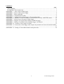
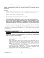
APPENDIX 1: Power input of data logger
1. Wiring of power connector
2. Parameters of power input
Power voltage of data logger is 24V DC. Consumption of data logger differs depending on kind of
connected peripherals. Approximate values are in the below table. If output relay module will be
connected to data logger, this voltage must be complied. Data logger itself is able to work at power
voltage range (9..30)V DC. Always it is necessary to consider if A0 inputs will be installed before
selection of power voltage. If it is to be, see, what lowest power voltage transmitters connected to
this input need. Select data logger power voltage at least 3V higher than this. It is necessary to warn
negative pole of power connector is galvanically connected to internal GND of data logger. Thus
also with inputs (if galvanically not isolated) and with voltage of ALARM output.
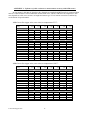
Approximate maximum current consumption
Power 24V
Power 9 V
Power 12V
data logger without input
modules
approximately
50 mA
approximately
100 mA
approximately
80 mA
data logger with display
without input modules, all
LEDs light
approximately
80 mA
approximately
180 mA
approximately
150 mA
Input modules galvanically not
isolated
< 3 mA
< 3 mA
< 3 mA
Input module galvanically
isolated and ac
approximately
13 mA
approximately
35 mA
approximately
25 mA
Input module A0 short circuited
at the input
approximately
28 mA
approximately
28 mA
approximately
28 mA
Output relay module, all relay
closed
approximately
200 mA
---
---
ie-ms2-ms5app-01.doc
3
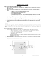
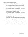
APPENDIX 2: Input circuits of data logger
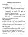
1. Connection of earthing terminals in data logger with galvanically not isolated inputs
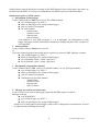
2. Input for two-wire connected passive transmitters - input type A0:
Note: All temperature and humidity transmitters Comet are connectable this way.
4
ie-ms2-ms5app-01.doc
3. Input for measurement of current 0(4) to 20 mA
Inputs for measurement of higher currents (1A and 5A) differs by the value of shunt resistor. Voltage
inputs have resistor divider instead of shunt resistor. Inputs for measurement of resistance have
reference voltage via suitable resistor connected to the IN terminal.
4. Concept of galvanically isolated analog inputs
ie-ms2-ms5app-01.doc
5
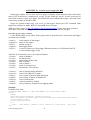
APPENDIX 3: Input module RS
What can be connected to the RS input module:
•
•
device, which is equipped with communication link RS485 (link is galvanically isolated at
RS module side)
device must support communication protocol ADVANTECH, single- and multi-channel
input:
- address of input device must be at range 1 to 16
- format data must be „Engineering units“
- check sum must be enabled
- supported communication speed: 1200 Bd, 2400 Bd, 4800 Bd, 9600 Bd or 19200 Bd
(9600 Bd is set from the manufacturer)
•
•
•
•
- input device can have maximum 8 inputs (for multi-channel instrument)
1 to 16 input device can be connected to one module
this module can be only one in data logger
maximum number of operated points depends on physical position of module in data logger
Comet transmitters Tx4xx or other manufacturer devices are connectable this way to data
logger
Example:
If module RS is located e.g. at position of data logger channel 6, then link RS485 connected to channel 6
works with data logger channels 6 to 16. Physical positions of input modules for channels 7 to 16 must be
vacant. At channels 1 to 5 any input modules can be (except input RS, which can be in data logger only
one).
How to set data logger together with input devices:
• Connect each from input devices one after another to the computer and set these parameters:
- address of input device from range 1 to 16 (each device must have its own address)
- suitable communication speed, for all device must be the same
- format of data "Engineering units"
- enable check sum
Some types of input device can require connection of internal jumper Init. Follow the rules
in manual for these devices.
• Connect input device to the RS485 network. Connect link to input terminals of data logger module
RS and switch on.
•
Example of connection to transmitter Comet:
6
ie-ms2-ms5app-01.doc
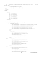
Run user SW for data logger and set the data logger: Configuration – Setting of data logger. Here
at bookmark Ch..Marking and conversions set for each channel these items:
- Device address (for RS485): enter address of input device operated from that data logger
channel. Address can be at range 1 to 16 (decimal).
-
Multi-input device: If this input device measures several values, then tick this field.
detailed information – see below description of protocol.
The number of input channel: valid for multi-input device. It is a number from 0 to 7
Maximum waiting time: how long data logger will wait for response from input device.
Adjustable at range 30 to 210 ms. If this response does not come, error is reported.
Communication speed – set the same speed you have set for input device before
After this setting RS module works with those inputs identically as with usual analog channels
Detailed specification of communication protocol
The RS module sends command for reading from input device. Command always contains
check sum.
Syntax of command:
A) reading from single-input device
#AA (CRC) (cr)
e.g. #0184(cr), accordingly 23h,30h,31h,38h,34h,0Dh
(CRC=23h+30h+31h=84h)
where
AA .. address of device (01h..10h)
CRC .. check sum
this command is request for data from device at address 01h
use: single-channel device (e.g. 4011,4012,4013,4014D, Comet N485 etc.)
B) reading from multi-input device
#AA(M)(CRC)(cr) e.g. #032B8 (cr) accordingly 23h,30h,33h,32h,42h,38h,0Dh
this command is request for data from device at address 03h from
channel 02h
ie-ms2-ms5app-01.doc
7
where
AA .. address of device (01h..0Fh)
M .. number of input of this device
use: poly-channel device (e.g. 4017, Comet NH485 etc.)
After sending command module is switched to reception and waits for response. Maximum
duration for waiting is possible to set. After the wait error is reported. Waiting duration for
response is adjustable from approximately 28 to 500 ms (see below point 5).
Device response: Module RS supports response format corresponding with "Engineering units"
protocol ADVANTECH:
>sxxxx.xxxx(CRC)(cr)
where
s ... sign
x ... digits, maximum number of digits left from decimal point is 11, right from
decimal point is 6
(attention to maximum process able number in data logger.. see below)
Note: nor decimal point, nor the sign is required (number is considered as positive)
Example: >+3456.12345(CRC=66)(cr), accordingly
3ch,2bh,33h,34h,35h,36h,2eh,31h,32h,33h,34h,35h,66h.0dh
Examples of valid formats: >23(CRC)(cr)
>-234.67(CRC)(cr)
>+3389(CRC)(cr)
(CRC)... check sum is the sum of all transmitted bytes before the check sum, transmission is
converted to ASCII code.
1.1.1.1 Example:
>35
transmitted are following bytes: 23h, 33h, 35h
CRC= 23h+33h+35h=8Bh
therefore is sent >358B(cr) i.e. 23h,33h,35h,38h,42h,0Dh
(cr) ... character 0Dh
8
ie-ms2-ms5app-01.doc
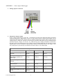
APPENDIX 4: Communication cables
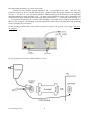
1.. Wiring diagram of communication cable RS232
This communication cable serves for direct connection of data logger to the computer.
3. Wiring diagram of communication cable between data logger and RS232/Ethernet converter
UDS10/100/1000
ie-ms2-ms5app-01.doc
9
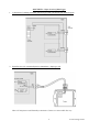
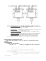
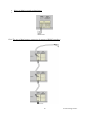
4. Wiring of RS485 terminals at data logger
5.
D4.4 The way of data loggers connection by means of RS485 interfaces
10
ie-ms2-ms5app-01.doc
Recommended parameters of connection leads:
Twisted two-wire, shielded, nominal impedance 100 Ω, loop resistance max. 240 Ω, max. 98 Ω/km,
maximum capacity 65 pF/m, crosstalk between pairs –40 dB/150 kHz. For longer distances use cabling in
one line, i.e. no „tree“ or „star“ (for shorter distances different topology can be tolerated). At the beginning
and end termination resistor should be (120 Ω). In many cases termination resistor can be omitted due low
communication speed. Marking of link leads from other manufacturers: „+“ corresponds with marking „A“,
„-“ corresponds with marking „B“. Connect cable shielding to each other, do not connect to transmitter, if
those are not equipped with shielding terminal galvanically isolated from communication and measuring
circuits, including case metal parts.
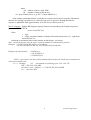
In case shielding of RS485 link is not possible to ground at computer side, ground at data logger nearest to
the computer:
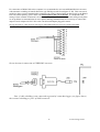
Wiring diagram of connection to RS232/RS485 converter:
ie-ms2-ms5app-01.doc
11
For connection of RS485 link to the computer it is recommended to use external RS485/RS232 converter
with automatic switching of transfer direction, type E06D powered from adapter 6V DC. This converter is
possible to plug to serial communication computer port COM. Connect link from data logger to the RS485
side with correct polarity (pins 3 and 4) and connect pins 2 and 7 to each other . It corresponds with
setting of time constant of automatic converter switching for speed 115200 Bd. At this setting mostly there
are no problems in communication at lower speed). During communication it is necessary to connect DC
output of ac/dc adapter 230V/6V DC to the converter and adapter plugged in mains.
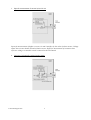
Wiring diagram of cable between data logger and RS485/Ethernet converter UDS10/100/1000
Wiring diagram of connection to USB/RS485 converter:
Note: if cable shielding is not connected to ground of some data logger (see figure above),
then connect shielding to pin 5 of SubD connector.
12
ie-ms2-ms5app-01.doc
APPENDIX 5: Configuration of data logger with external modem
There are two applicable ways to connect data logger to telephone network (land line or GSM):
A) modem is controlled by the data logger - connect data logger to computer via RS232 link by
means of the delivered cable. Switch ON data logger and enter mode of configuration setting. Set
interface RS232-modem and enter configuration chain for modem (it consists of AT statements). It
is recommended to use preset chains for modem for land line and for GSM modem (these chains
contain below statements for "manual" modem setting). Then connect via modems, install the
drivers for modem at computer side (if needed) and set communication in the PC (enter telephone
number, COM port etc.). Try to communicate - see below point 4 Function verification.
B) modem is set "manually" by the user
Instructions for "manual" communication setting by means of modems:
Configuration of data logger´s communication interface
Connect data logger via RS232 link to the computer (included cable), switch on and run user
PC program. Choose selection RS232- modem from Configuration menu.
Configuration of external modem at data logger side
Connect modem to computer by a cable, which is the accessory of the modem, plug in the
ac/dc adapter and switch ON the modem. Run HyperTerminal program on your computer (it is
located in Accessory - Communication). After its running a request of creation of new connection
appears. Cancel this request. In menu File - Parameters choose in item Connect by means of
selection Directly to port COM1 (respectively COM2, if modem is connected to communication
port COM2). Choose selection Configuration at the same window and set parameters Number of
bits per second to 19200, Number of data bits to 8, Parity: no, Stop-bits: 1, Flow control:
hardware. Confirm both windows to return to terminal. Here enter command AT (cr) (i.e. enter in
upper case letters AT and press the Enter key). Modem must response: OK.
Setting of modem for land line
Now it is necessary to configure modem itself in the way modem after reception must
"hung-up" (disconnect the call) and cancel the control of the DTR-DSR loop. This can be done as
follows:
a) AT&Y0 cr (selection of user template 0)
b) ATS0=1 cr (modem „hang-up after the call”)
c) ATS23=060 cr (communication speed 19200 Bd)
d) AT&D1 cr (cancel of testing DTR-DSR loop)
e) AT&W0 cr (saving of active configuration to profile 0)
Now modem is configured and can be switched OFF. Modem responds OK to each commands.
Notice: Be careful not to send to modem AT command in other communication speed. It could
cause modem reconfiguration.
Note: The above description was verified with modems Microcom DeskPorte 56k Voice, ASKEY V
1456 VQE R-1 and ORIGO FM-56DT.
2.2. Setting of GSM modem - SIM card used in GSM modem must be set not to require PIN after
switching ON th emodem power. Modem should be set to automatically pick up the call and to
enter data mode immediately.
Example for GSM modem WAVECOM WMOD2B:
a) AT+CICB=0 (automatic jump to data mode)
ie-ms2-ms5app-01.doc
13
b) ATS0=1 (automatic call pick-up after first ring)
c) AT&W (configuration writing to EEPROM memory).
Logger should be set to 9600Bd communication speed, because the above modem type is not able
to communicate faster.
Configuration of modem at computer side
Connect modem (if external) to the computer by an accessory cable of modem and switch on
the power. Switch on the computer or restart it. In case modem is not installed, system Windows
could run installation wizard. A CD included in delivery of modem is required. The following
steps presume modem is installed correctly.
Function verification
Let modem connected to computer (if external) and connect phone line to its LINE input.
Connect second modem configured in accordance with point 2 to data logger to the RS232
connector RS232. Use cable, which is the accessory of modem(!). Connect second phone line to
the LINE connector of this modem. Switch on modem and data logger. Run user program for data
logger. Define New Communication Device in menu Configuration – Setting of communication –
select modem and set its parameters. Select New Data Logger at the lower part of the window and
enter desired telephone number. Number of repetition is the number of trials to communicate.
Confirm window and try to read configuration. After confirmation modems start to communicate
and required data from logger is downloaded.
What to do if connection does not work
If communication via modems does not work and data logger itself communicates with the computer,
check first if wiring and each setting are correct. Pay attention to connection cables, which must be original
to modems. Cable included in data logger is designed only for direct connection between computer and data
logger. If everything is correct it is useful to test communication between two computers. Modem, which
was at data logger side connect to the first computer and run Hyperterminal. Connect modem, which was at
the computer to the second computer (it is supposed, it is already installed) and also run Hyperterminal.
Here in contrary with the first computer create new connection with telephone number of link, first modem
is connected to. Now there is no other way out than take modem user manual and try to create bothdirection data connection at suitable communication speed.
14
ie-ms2-ms5app-01.doc
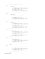
APPENDIX 6: Influence of cable resistance to measurement accuracy with RTD sensors
In case inputs J (Ni1000), K (Pt100) or K1 (Pt1000) are installed and RTD probe is connected, then
non zero cable resistance causes additional measurement error, which is added to real temperature. This
error depends on cable cross-section, its length and sensor type. If it is known correction is enabled by
recalculation of input channels.
Added error for copper wire (two wires) at temperature 23°C:
Cable cross-section
[mm2]
0,22
Cable length [m]
0,34
0,50
1,00
1,50
2,00
2,50
Added error for Ni1000/6180ppm [°C]
1
2
5
10
0,02
0,04
0,12
0,24
15
0,36
Cable length [m]
0,01
0,03
0,07
0,15
0,01
0,02
0,05
0,10
0,00
0,01
0,02
0,05
0,00
0,00
0,01
0,03
0,00
0,00
0,01
0,02
0,00
0,00
0,01
0,02
0,23
0,16
0,08
0,05
0,04
0,03
Added error for Pt100/3850ppm [°C]
1
2
5
10
0,36
0,73
1,82
3,64
0,24
0,47
1,18
2,36
0,16
0,32
0,80
1,60
0,08
0,16
0,40
0,80
0,05
0,11
0,27
0,53
0,04
0,08
0,20
0,40
0,03
0,06
0,16
0,32
15
5,47
3,54
2,40
1,20
0,80
0,60
0,48
Cable length [m]
Added error for Pt1000/3850ppm [°C]
1
2
5
10
0,04
0,07
0,18
0,36
0,02
0,05
0,12
0,24
0,02
0,03
0,08
0,16
0,01
0,02
0,04
0,08
0,01
0,01
0,03
0,05
0,00
0,01
0,02
0,04
0,00
0,01
0,02
0,03
15
0,55
0,35
0,24
0,12
0,08
0,06
0,05
1,50
2,00
2,50
Added error for copper wire (two wires) at temperature 100°C:
Cable cross-section
[mm2]
0,22
Cable length [m]
0,50
1,00
Added error for Ni1000/6180ppm [°C]
1
2
5
10
0,02
0,04
0,10
0,20
15
0,30
Cable length [m]
0,01
0,02
0,06
0,13
0,01
0,02
0,04
0,09
0,00
0,01
0,02
0,04
0,00
0,00
0,01
0,03
0,00
0,00
0,01
0,02
0,00
0,00
0,01
0,02
0,20
0,13
0,06
0,04
0,03
0,02
Added error for Pt100/3850ppm [°C]
1
2
5
10
0,37
0,75
1,86
3,73
15
5,60
Cable length [m]
ie-ms2-ms5app-01.doc
0,34
0,24
0,48
1,21
2,41
0,16
0,33
0,82
1,64
0,08
0,16
0,41
0,82
0,05
0,11
0,27
0,55
0,04
0,08
0,21
0,41
0,03
0,07
0,16
0,33
3,62
2,46
1,23
0,82
0,62
0,49
Added error for Pt1000/3850ppm [°C]
1
2
5
10
0,04
0,07
0,19
0,37
0,02
0,05
0,12
0,24
0,02
0,03
0,08
0,16
0,01
0,02
0,04
0,08
0,01
0,01
0,03
0,05
0,00
0,01
0,02
0,04
0,00
0,01
0,02
0,03
15
0,56
0,36
0,25
0,12
0,08
0,06
0,05
15
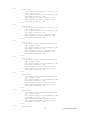
APPENDIX 7: Selected error messages of data logger
Error
number
1
MEANING
2
A/D converter is at upper limitation (input quantity – is over upper limit of module range)
3
RS input module did not receive response from connected device in adjusted time
10
counter module does not contain valid data
130
input module was not found
137
counter value is not possible to display (it contains more than 10 digits) – only display error
160-177
corruption of configuration areas of data logger
178
installed different type of module
179
upgrade of input module was not performed
187-188
unauthorized access (non valid password)
189
error of measurement of thermocouple cold junction
A/D converter is at lower limitation (input quantity – is below lower limit of module range)
16
ie-ms2-ms5app-01.doc
APPENDIX 8: Support of reception and sending of SMS messages
Data logger enables to respond to SMS query and sending SMS alarm messages.
Hardware requirements:
- data logger with FW version 2.0 and higher
- GSM modem connected to data logger, modem must support PDU SMS format and
its SIM card must have stored SCA number (Service Center Address)
There are the following connection modes:
a) modem is connected to main RS232 interface – used in case, modem is used both for data
and SMS communication (data logger is at distant place without PC). Advantage is a
simple connection, disadvantage can be potentially possible short dropouts
in communication with master PC in time, when data logger contacts the modem. Lower
transmission speed can be another disadvantage. Data logger tests requests for
reception/sending of SMS messages each two minutes. If data communication runs
(download of record values, change of configuration, the Display mode), then SMS
processing is backed away to 2 minutes after last data communication with data logger.
In this mode data transfer has higher priority than SMS message. It is not recommended
to monitor the data logger in the Display mode permanently.
b) modem is connected to main RS232 interface of data logger and the PC is connected to
RS485 interface of data logger. Data logger is set to RS232 (not to RS232-modem). In
this case data logger connects the modem, if there was at least two minutes delay
in communication with the PC. During communication with modem data logger does not
response to queries from the PC till the end of transaction with GSM modem (at the
moment RS485 is set to sending and reception from the PC is blocked and thus the
possibility of data collision).
Data logger function is verified with GSM modem Wavecom WMOD2.
Format of received SMS messages:
PDU format, support of 7 bit, 8 bit a 16 bit coding without compression, telephone number in
international/national format, ISDN/telephone numbering plan, maximum 15 characters of
telephone number, maximum length of text message 64 characters, message can contain UHD of
36 character maximum length, TP-PID= 00h (Short Message Type 0). If those parameters are
matched, message is accepted and decoded by data logger, i.e. UDH block is removed, text is
converted to capital letters and compared with predefined strings: Info, Alarm, Ch1 to Ch16. In
case valid string was received (no matter if capital/lower-case letters), data logger sends proper
response and received message is cleared from modem. If received SMS message is not valid it is
cleared from modem without sending any response.
Format of sent SMS messages:
PDU format, 7 bit coding without compression, telephone number in international format
maximum length 15 characters, Validity period: 3 days, with all messages except response to
request Info one SMS is sent of maximum 160 characters. In response to request Info sequence of
one to four SMS messages is sent (depending on configuration of data logger), maximum length is
152 characters for a message. Messages contain UDH with code for linking to one long SMS on
mobile telephones, which support linking of SMS together. For proper function it is necessary to
have telephone number SCA (Service Center Address) stored on SIM card of the modem.
With messages sent due to creation of alarm or critical state, after SMS is sent all alarm
states in data logger are stored. If no change in alarms appears, another message is not sent. If
alarm stops to be active and appears again, message is sent. If alarm at another channel appears,
message is sent again (If it is allowed by the user). If critical error state for sending SMS appeared
ie-ms2-ms5app-01.doc
17
(defined delay expired) and before sending of this SMS appeared new critical states, the states are
included into the SMS. It is always recommended to set suitable hysteresis and alarm delay.
Detailed description of SMS content:
1. Information on data logger
is sent if SMS with text Info was received. Then SMS contains:
• type of data logger (e.g. MS3+)
• name of data logger (see setting of data logger)
• state of memory occupation
• for each channel:
- channel name
- measured value
- physical unit
- state of alarms
Total number of sent SMS messages is 1 to 4 depending on configuration of data
logger. Messages contain information intended for linking together at the recipient to
one long SMS.
2. State of alarms
is sent if SMS with text Alarm was received
or
if at some channel appeared new alarm and is required its report by SMS. Message contains:
• type of data logger (e.g. MS3+)
• name of data logger (see setting of data logger)
• list of channels, where Alarm 1 appeared
• list of channels, where Alarm 2 appeared
3. Information on particular channel
is sent if SMS with text Chn (where n is channel number 1 to 16). Message contains:
• type of data logger (e.g. MS3+)
• name of data logger (see setting of data logger)
• state of memory occupation
• information on specified channel:
- channel name
- measured value
- physical unit
- state of alarms
4. Message on creation of critical state
is sent if critical error state in data logger appeared and SMS report is required.
Message contains:
• text WARNING!
• type of data logger (e.g. MS3+)
• name of data logger (see setting of data logger)
actual list of critical states in data logger (selftest error, configuration, measurement, overrun
of adjusted limit, fulfilling of memory)
18
ie-ms2-ms5app-01.doc
APPENDIX 9: Setting of communication with data logger via Ethernet
Setting depends on type of communication device. Below are described general steps and
examples illustrate data logger equipped with own Ethernet interface or with converter UDS-1000
from Lantronix.
Procedure:
1. Probably knowing of MAC address of converter or data logger is necessary (if it is equipped
with Ethernet interface). MAC address is mostly specified on the manufacturer label.
Example of MAC address: 00-20-4A-80-F2-FB
2. Ask administrator of your network to assign free IP address
Example of IP address: 194.168.1.211
3. Connect data logger to Ethernet network (directly or via converter) and switch on its power
4. Run user SW for data logger and in window Configuration - Setting communication display
parameters of the Ethernet communication device (button New or Change) and use selection
Search (next to IP address). If device is not found (detect e.g. by means of disconnecting
from Ethernet network and see, if there is any change in the search), then follow the below
instruction.
5. If connection is not successful, try to disconnect the computer from the network and use
crossed Ethernet cable to connect data logger to the computer directly and repeat the setting.
If IP address is set correctly, communication device is found, but data logger does not work,
check setting of Communication interface. Best way is to check on display of data logger: must
be set to Ethernet.
Solving problems with communication:
A) data logger is connected to the network by external converter (UDS100, UDS1000,
UDS1100...):
Problem can be in setting of communication interface and communication speed of Ethernet
output itself. In this case proceed this way:
Run internet browser and enter directly data logger IP address (it is necessary to have
installed Java script), wait for reading of www pages of this device.
Enter at bookmark Port Properties or Channel 1:
- Serial protocol:
RS232, if data logger contains Ethernet interface or you communicate with data
logger connected to converter UDS-10 connected to RS232 interface of data logger
RS485-2 wire, if converter is connected to RS485 interface of one or several data
loggers
- Speed – communication speed, must be the same, as set on data logger itself (can
be found from data logger menu of MS5D LCD)
- Character Size: 8, Parity: None, Stopbit: 1, Flow Control: None, UDP Datagram
Mode: Disable, Remote IP Address: same as used before, Local Port: 10001,
Disconnect Mode: Ignore DTR, Other items: Disabled
Save the configuration to the device finally and try to find data logger again.
ie-ms2-ms5app-01.doc
19
B) Data logger is equipped with internal Ethernet interface
•
In the window of device finding only IP and MAC address are displayed
Other details are marked as N/A. This problem appears in case, IP address of data
logger is set to different network, than network data logger is actually connected to.
Select in program menu Configuration - Setting communication – Change – Find Change IP address. Follow instructions from the PC program.
•
IP address is not displayed even in the window for device finding
Select in program menu Configuration - Setting communication – Change – Find Help! My device wasn’t found!. Follow instructions from the PC program.
•
Device is not found even after manual entering of MAC address
This problem appears especially in cases, IP device belongs to different network and
at the same time incorrect gate address and mask is specified.
Select in program menu Configuration - Setting communication – Change – Find Help! My device wasn’t found!. In window Set IP to ARP only, enter data
logger MAC address isolated by hyphens to the cell Device MAC address (e.g. 0020-4A-84-F0-80) and press button “Set IP“.
Run command line of system Windows (Start/run) and enter telnet new
IP_address 9999. You get to the text mode of setting data logger interface (e.g.:
telnet 192.168.1.211 9999).
Press enter key and 0 - Global Settings, set IP address of the device, cancel IP address
of gate, set number of mask bits to 0. Confirm the rest by enter key to get to menu.
Here save setting by selection 9 Save and Exit. Then connection is closed. Now it is
possible to connect to data logger by the program.
•
Communication with program works, but it is not possible to change setting of
data logger Ethernet interface
If data logger is set to communicate with the program (it is possible to read the
Display mode, download data etc.), but configuration of Ethernet interface cannot
be changed (e.g. IP address of traps, IP address of data logger…), probably you
have adjusted high level of security. Proceed in accordance with the Service
manual.
20
ie-ms2-ms5app-01.doc
APPENDIX 10: Creation of www pages for MS5
Data logger enables user to store own web pages to display actual measured values and alarm
states. Files web2cob.exe, mimetype.ini, ron.gif, al2.gif, alarm.gif, led.gif will be necessary for
successful creation of own www pages. Download files from manufacturer pages. Also tftp client
is necessary (default in Windows XP).
Pages are created in html code, web server of data logger detects the GET command. Data
logger has available six banks WEB1-6 after 64kB for www pages.
Address of www pages is http://IP_address_data logger/page.html. If your main page is named
index.html, only enter data logger IP address in internet browser to address of pages.
Procedure of www pages creation
Create HTML pages in any editor. Enter proper mark to the point where values from data logger
are meant to be located:
<%srn%>
<%name%>
<%rfr%>
<%type%>
<%fw%>
serial number of data logger
name of data logger
refresh of pages
data logger model
version of firmware of data logger Ethernet interface (it is different from FW
version of data logger itself)
Valid for all 16 channels; enter 1 for required channel:
<%c1n%>
name of channel 1
<%c1v%>
measured value
<%c1u%>
physical unit of the value
<%c1a%>
state of alarm 1
<%c1b%>
state of alarm 2
<%c1p%>
name of actual process
<%c1r%>
information, if record runs
<%iacs%>
<%oacs%>
<%iap%>
<%oap%>
<%tico%>
<%slft%>
<%ram%>
state of internal audio indication
state of ALARM OUT output
icon of state of internal audio indication
icon of state of output ALARM OUT
icon of selftest state
values measured by selftest
state of memory occupation and logging mode
Example:
Example of the code :
<!DOCTYPE HTML PUBLIC "-//W3C//DTD HTML 4.01 Transitional//EN">
<html>
<head>
<meta http-equiv="refresh" content="<%rfr%>">
<meta http-equiv="content-type" content="text/html; charset=windows-1250">
<title>values</title>
<style type="text/css">
<!-body{
font-family: verdana, arial, helvetica, sans-serif; font-size:
76%;
ie-ms2-ms5app-01.doc
21
color: #000;
background-color: #fff; }
h1{
font-size: 2.0em; font-weight: normal;margin-top: 0em;
bottom: 0em;}
.a1 {background-color: red;}
.a2 {background-color: yellow;}
.a0 {background-color: #d3d3d3;}
//-->
</style>
</head>
<body>
<script>
p1 = new
p1.src =
p2 = new
p2.src =
p3 = new
p3.src =
p4 = new
p4.src =
</script>
margin-
Image();
"ok.gif";
Image();
"al1.gif";
Image();
"al2.gif";
Image();
"ron.gif";
<h1>Monitoring:</h1>
<table border="1" cellpadding="2" cellspacing="0">
<tr bgcolor="#bbbbbb">
<td><b>Nr.</b></td>
<td width="180px" align="center"><b>Channel name</b></td>
<td><b>R</b></td>
<td width="180px" align="center"><b>Value</b></td>
<td width="80px" align="center"><b>Unit</b></td>
<td width="20px" align="center"><b>I.</b></td>
<td width="20px" align="center"><b>II.</b></td>
<td width="180px" align="center"><b>Process</b></td>
</tr>
<tr>
<td>1</td>
<td align="left"> <%c1n%></td>
<td><%c1r%></td>
<td align="right"><%c1v%> </td>
<td> <%c1u%></td>
<td><center><%c1a%></center></td>
<td><center><%c1b%></center></td>
<td> <%c1p%></td>
</tr>
<tr>
<td>2</td>
<td align="left"> <%c2n%></td>
<td><%c2r%></td>
<td align="right"><%c2v%> </td>
<td> <%c2u%></td>
<td><center><%c2a%></center></td>
<td><center><%c2b%></center></td>
<td> <%c2p%></td>
</tr>
<tr>
<td>3</td>
<td align="left"> <%c3n%></td>
<td><%c3r%></td>
<td align="right"><%c3v%> </td>
<td> <%c3u%></td>
<td><center><%c3a%></center></td>
<td><center><%c3b%></center></td>
22
ie-ms2-ms5app-01.doc
<td> <%c3p%></td>
</tr>
<tr>
<td>4</td>
<td align="left"> <%c4n%></td>
<td><%c4r%></td>
<td align="right"><%c4v%> </td>
<td> <%c4u%></td>
<td><center><%c4a%></center></td>
<td><center><%c4b%></center></td>
<td> <%c4p%></td>
</tr>
<tr>
<td>5</td>
<td align="left"> <%c5n%></td>
<td><%c5r%></td>
<td align="right"><%c5v%> </td>
<td> <%c5u%></td>
<td><center><%c5a%></center></td>
<td><center><%c5b%></center></td>
<td> <%c5p%></td>
</tr>
<tr>
<td>6</td>
<td align="left"> <%c6n%></td>
<td><%c6r%></td>
<td align="right"><%c6v%> </td>
<td> <%c6u%></td>
<td><center><%c6a%></center></td>
<td><center><%c6b%></center></td>
<td> <%c6p%></td>
</tr>
<tr>
<td>7</td>
<td align="left"> <%c7n%></td>
<td><%c7r%></td>
<td align="right"><%c7v%> </td>
<td> <%c7u%></td>
<td><center><%c7a%></center></td>
<td><center><%c7b%></center></td>
<td> <%c7p%></td>
</tr>
<tr>
<td>8</td>
<td align="left"> <%c8n%></td>
<td><%c8r%></td>
<td align="right"><%c8v%> </td>
<td> <%c8u%></td>
<td><center><%c8a%></center></td>
<td><center><%c8b%></center></td>
<td> <%c8p%></td>
</tr>
<tr>
<td>9</td>
<td align="left"> <%c9n%></td>
<td><%c9r%></td>
<td align="right"><%c9v%> </td>
<td> <%c9u%></td>
<td><center><%c9a%></center></td>
<td><center><%c9b%></center></td>
<td> <%c9p%></td>
</tr>
ie-ms2-ms5app-01.doc
23
<tr>
<td>10</td>
<td align="left"> <%c10n%></td>
<td><%c10r%></td>
<td align="right"><%c10v%> </td>
<td> <%c10u%></td>
<td><center><%c10a%></center></td>
<td><center><%c10b%></center></td>
<td> <%c10p%></td>
</tr>
<tr>
<td>11</td>
<td align="left"> <%c11n%></td>
<td><%c11r%></td>
<td align="right"><%c11v%> </td>
<td> <%c11u%></td>
<td><center><%c11a%></center></td>
<td><center><%c11b%></center></td>
<td> <%c11p%></td>
</tr>
<tr>
<td>12</td>
<td align="left"> <%c12n%></td>
<td><%c12r%></td>
<td align="right"><%c12v%> </td>
<td> <%c12u%></td>
<td><center><%c12a%></center></td>
<td><center><%c12b%></center></td>
<td> <%c12p%></td>
</tr>
<tr>
<td>13</td>
<td align="left"> <%c13n%></td>
<td><%c13r%></td>
<td align="right"><%c13v%> </td>
<td> <%c13u%></td>
<td><center><%c13a%></center></td>
<td><center><%c13b%></center></td>
<td> <%c13p%></td>
</tr>
<tr>
<td>14</td>
<td align="left"> <%c14n%></td>
<td><%c14r%></td>
<td align="right"><%c14v%> </td>
<td> <%c14u%></td>
<td><center><%c14a%></center></td>
<td><center><%c14b%></center></td>
<td> <%c14p%></td>
</tr>
<tr>
<td>15</td>
<td align="left"> <%c15n%></td>
<td><%c15r%></td>
<td align="right"><%c15v%> </td>
<td> <%c15u%></td>
<td><center><%c15a%></center></td>
<td><center><%c15b%></center></td>
<td> <%c15p%></td>
</tr>
<tr>
<td>16</td>
24
ie-ms2-ms5app-01.doc
<td align="left"> <%c16n%></td>
<td><%c16r%></td>
<td align="right"><%c16v%> </td>
<td> <%c16u%></td>
<td><center><%c16a%></center></td>
<td><center><%c16b%></center></td>
<td> <%c16p%></td>
</tr>
</table>
</body>
</html>
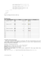
Pages are displayed in browser this way:
Compilation and upload of pages
Store pages for upload to data logger to one directory. The above required pictures store to the
same directory with you r pages. Run program web2cob.exe to create .cob file. Upload this file by
means of tftp protocol to data logger.
Parameters of program web2cob.exe:
Web2CoB [/o <output file>] [/d <directory>]
Output file: Name of output file. Preset name is cobox.cob.
Directory: Source directory with www pages.
Parameters of tftp transfer: select binary transfer, method PUT. Select target address from
WEB1 to WEB6.
Note: File mimetype.ini must be located in the same directory as Web2Cob.exe
ie-ms2-ms5app-01.doc
25
Example:
Data logger has IP address 192.168.1.205. In directory c:\MS\www are located www pages.
In directory c:\MS are files Web2Cob.exe and mimetype.ini. Go to the directory
c:\MS and enter command:
web2cob.exe /d www /o TESTWEB.cob
In directory c:\MS file TESTWEB.cob is created.
Upload www pages to data logger by command tftp -i 192.168.1.205 PUT
TESTWEB.COB WEB1, memory area WEB1
Limitation:
Maximum size of one WEB (cob) page is 64kB. In case size of www page exceeds 64kB,
divide it to max. 6 blocks, compile one after another and store to areas WEB1-WEB6
Each tag of type <% %> must be located on separate line in source file.
Capacity of www server of data logger is limited. The bigger the pages are, the lower number of
possible simultaneous accesses will be.
26
ie-ms2-ms5app-01.doc
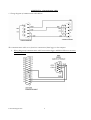
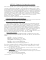
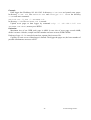
APPENDIX 11: Connection of data logger with output relay module and external terminal
module
ATTENTION – cable is crossed, if wired different way than on the figure, connected circuits
can be damaged !
ie-ms2-ms5app-01.doc
27
APPENDIX 12: Setting of client administration and passwords
This APPENDIX describes security of data logger MS+ against illegal access. This issue is applied
in following levels:
•
•
•
Encryption of transferred data in communication with data logger
Protection against illegal access to program and limitation of its functionality in accordance
with setting of user rights
Protection against illegal access to setting of data logger and limitation of configuration
options in accordance with setting user rights.
1. Encryption of data in communication with data logger
is a way of protection of transferred data between computer and data logger by means of client
specified password. The reason is protection against interception of transferred data via cable links
or intranet/internet, that could be decoded based on available documentation of communication
protocol of data logger.
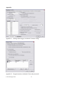
Encryption of communication data and password for data logger is activated in setting of data
logger in bookmark “Common setting” in section “Communication interface of data logger“ see
appendix 1.
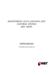
In options of program in bookmark „Users and passwords“ in section „Password for data
encryption“ (see appendix 2) is possible to set way to enter password for encryption of
communication:
•
•
Password will be permanently stored in the computer
At first opening of communication with data logger client is invited to enter password.
Password is stored and used further in communication with data logger even after re-run of
the program
Password will be memorized only to the end of application
After running the program and opening of communication with data logger client is invited
to enter password, which is memorized only during program run and after exiting program
is no longer valid.
1. Administration of clients
List of authorized clients for access to program or to setting of data logger and their rights is
possible to set in program options in section „User list“, see appendix 2.
„User list“ can contain up to 16 clients with the following parameters:
„User name“ – unique user name for access to account
„Password“ – password for access to account
„Name and surname“ – name and surname of client
„Description“ – description of user account
„Group membership“ – membership in group of clients
• „User with limited privileges“ – access to SW and HW protected functions is enabled to
define except for rights to administrate the clients.
• „Administrator“ – member of this group has unlimited access to SW and HW protected
functions including administration of clients.
28
ie-ms2-ms5app-01.doc
„SW protected functions“ – are functions accessible by client in work with program in itself
„HW protected functions“ – are functions accessible by client in work with data logger
„Create new password“ – entering of new password of client
„Export“ – exports list of clients to the file
„Import“ – reads list of clients from the file
List of clients stored to the file is possible to use for transfer of clients between program
installations on more computers or for theirs back-up. Always store this file to a safe place.
3. Protection against illegal access to program and limitation of its functionality in
accordance with setting user rights
limits access to program and its „SW protected functions“ only to clients defined in section „User
list“, in accordance with their rights. It is activated in program options in bookmark „Users and
passwords“ in section „Password protection“, see appendix 2.
If „Password protection“ is activated, after program run client is invited to login to his user account
defined in „User list“.
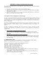
Figure 1 „Login dialog“
The way to authorize client in access to „SW and HW protected functions“ is set program options
in bookmark „Users and passwords“ in section „How to execute login dialog“
• At application startup only
User account client is logged in after program run will be used automatically to authorize
access to „SW and HW protected functions“, i.e. without the need to authorize again in
„Login dialog“.
It is a lower protection grade, not protecting running program against misuse of the third
party.
• Before every protected function
After running of any „SW and HW protected function“ client must authorize again in
„Login dialog“ to his user account in „User list“.
It is a higher protection grade, protecting local access to program functions anytime, i.e.
even in case when currently logged-in client let program running and leave his computer.
„SW protected functions“ are the following:
• „Setting of program options“ – setting of program options as Folders, Display and
Automatic data download.
• „Setting of communication“ – setting of communication devices and data loggers.
• „Clear display statistics“ – erasing of statistic data of active data logger in Display on
bookmark display.
ie-ms2-ms5app-01.doc
29
•
•
„Clear alarms“ – erasing of alarm of active data logger on bookmark „alarms“.
„Delete event viewer messages“ – erasing of messages in event viewer.
Access rights of client to those functions are defined in his user account. Logout of current client is
enabled by selection „User Logout …“ from menu File.
4. Protection against illegal access to setting of data logger and limitation of configuration
options in accordance with adjusted user rights
Limits access to setting and „HW protected functions“ only for clients defined in „User list“ stored
in data logger in accordance with their rights. Way of definition of „User list“ for data logger is
specified by setting „Use same security setting and user list for all data loggers“ on bookmark
„Users and passwords“ in section „Security setting and user administration“, see appendix 2.
„Use same security setting and user list for all data loggers“ has the following meaning
• Enabled – defines „User list“ for all available data logger identically based on „User list“
for program and gives notice to client with administrator rights to the need of update of
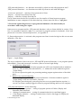
„User list“ in data logger, see figure 2.
Figure 2: Prompt to update „User list“ stored in available data loggers
In case data logger does not contain any client in its configuration program gives notice to
the need to activate „Communication data encryption by password“, see above and invites
to enter the password, see figure 3.
Figure 3: Invitation to enter necessary password for encryption of communication data
In dialog setting of data logger at bookmark “Common setting” in section “Communication
interface data logger“ is then enabled „Protection of access to HW functions“, but prohibited
30
ie-ms2-ms5app-01.doc
editing of clients stored in data logger by „Users and passwords“ button see appendix 1.
Manual update of „User list“ stored in data logger from „User list“ for program is then enabled
by selection “Update users and passwords in data logger“ from menu Configuration.
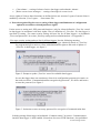
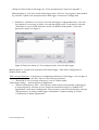
•
Prohibited – definition of „User list“ stored in data logger is independent from „User list“ for program it is necessary to define it in each data logger itself. Is activated by selection
„Protection of access to HW functions“ and it is defined in dialog under „Users and
passwords“ button, see figure 4.
Figure 4 Dialog for editing of „Users and passwords“ stored in data logger
Manual update of “Update users and passwords in data logger“ from menu Configuration is
disabled in this mode.
„HW protected functions“ of program are configuration functions for data logger. Access rights of
client are defined in its user account. There are the following functions:
• „Download of record, erasing of memory, reset of counter inputs“
„Data logger setting“ – item from menu Configuration.
• „Alarm confirmation by PIN“ – PIN client for alarm cancel from keyboard of data logger
or from program by selection of item „Deactivate internal acoustics or ALARM OUT
signalization“ from menu Configuration. The necessity to enter PIN is defined by selection
„PIN protection“ in setting of data logger at bookmark „Common setting“ in section
„Confirmation of alarm signalization“
ie-ms2-ms5app-01.doc
31
5. Administration of clients
From the above results the following:
• Administration of clients and passwords in program is activated by selection „Password
protection“ at bookmark „Users and passwords“ from menu program.
• Define available clients and theirs parameters in section „User list“ an the same bookmark
- see paragraph 2 Administration of client. Editing of „User list“ is enabled only to client
with rights of administrator.
• Critical for work on administration of clients is the selection of its mode, thus „Use same
security setting and user list for all data loggers“ in section „Security setting and user
administration“ at the same bookmark, see paragraph 4 Protection against illegal access to
setting of data logger and limitation configuration of capability in accordance with setting
of user rights.
Note, there will be always two lists of clients - one stored in program and one stored in data
logger.
Selection mode „Use same security setting and user list for all data loggers“ determines the
way to create and administer the client list in data logger.
If this mode is active then program defines client list stored in data logger based on list of
clients stored in program, i.e. as „User list“ at bookmark „Users and passwords“ in program
options. Then program user is responsible for client list update in data logger by
confirmation of the dialog from figure 2 or manually by selection “Update users and
passwords in data logger“ from menu Configuration. Thus „Users and passwords“ button in
section „Data logger communication interface“ becomes inactive in setting of data logger,
see appendix 2.
With favor it is possible to use this mode in smaller monitoring systems i.e. one control
computer and several data loggers with maximum of 16 clients.
•
•
If this mode inactive, then list of clients stored in program is independent from list of
clients stored in data logger and program does not supervises its updating. List of clients
stored in data logger is activated by selection „Protection of access to HW functions“ then
defines in dialog under „Users and passwords“ button in setting of data logger, see
appendix 1, figure 4.
With favor it is possible to use this mode in larger monitoring systems i.e. several control
computers and more networked data loggers with many clients. Here it is possible to divide
clients to smaller groups (maximum of 15 clients) and define theirs access to data logger
groups (by means of export and import of client list to the file) and at the same time to keep
centralized administration by one administrator.
Allowance of administration of clients requires allowance of encryption data in
communication with data logger, see paragraph 1. Allowance of encryption must be
specified before first storing of the client list to data logger.
Deactivation of administration of clients is performed by switching off the selection
„Password protection“ at bookmark „Users and passwords“ in program options, see
appendix 2 and by switching off the selection „Protection of access to HW functions“ in
section „Data logger communication interface“ in setting of data logger, see appendix 1.
32
ie-ms2-ms5app-01.doc
Appendix:
Appendix 1 – Setting of data logger, bookmark Common setting
Appendix 2 – Program Options, bookmark Users and passwords
ie-ms2-ms5app-01.doc
33