1
ADAM 4000
Data Acquisition Modules
User's Manual
ADAM 4000 Series
Data Acquisition Modules
User’s Manual
Copyright Notice
This d ocument i s copy righted, 1997, by Advantech C o., Lt d. All ri ghts are
reserved. Advantech C o., Ltd., re serves t he ri ght t o m ake i mprovements t o t he
products described in this manual at any time without notice.
No pa rt of t his m anual m ay be re produced, c opied, t ranslated o r t ransmitted i n
any form or by any means without the prior written permission of Advantech Co.,
Ltd. Information provided in this manual is intended to be accurate a nd reliable.
However, Advantech Co., Ltd. assumes no responsibility for its u se, nor for any
infringements upon the rights of third parties, which may result from its use.
CE Notification
The A DAM-4000 se ries de veloped by A dvantech C o., Ltd. ha s passe d t he C E
test for environmental specifications when operated within an industrial enclosure
(ADAM-4950-ENC). The refore, i n o rder t o p rotect t he ADAM m odules fr om
being damaged by ESD (Electric Static Discharge), we st rongly recommend that
the use o f C E-compliant i ndustrial encl osure p roducts when usi ng any A DAM
module.
Acknowledgments
ADAM is a trademark of Advantech Co., Ltd.
IBM and PC are trademarks of International Business
Machines Corporation.
Edition 10.7
May 2008
Table of Contents
Chapter 1 Introduction ..….....……..................…..................…….. 1-1
1.1 Overview .......................…................................….........….…… 1-2
1.2 Applications ..................….........................…….............…....... 1-4
Chapter 2 Installation Guideline ...................….................…....... 2-1
2.1 System Requirements to set up an ADAM network ..….......
2.2 Basic configuration and hook-up ....................……...............
2.3 Baud rate and Checksum .................................……...............
2.4 Multiple Module Hookup ...............................………...............
2.5 Programming Example.....................................……................
2-2
2-6
2-9
2-11
2-12
Chapter 3 I/O Modules ..................................................…............. 3-1
3.1 ADAM-4011/4011D Thermocouple Input Modules ...…......... 3-3
3.2 ADAM-4012 Analog Input Module ………………..…............... 3-10
3.3 ADAM-4013 RTD Input Modules .......………………….…….... 3-15
3.4 ADAM-4015 6-channel RTD Input Module .…………….......... 3-17
3.5 ADAM-4015T 6-channel Thermistor Input Module ....…........ 3-20
3.6 ADAM-4016 Analog Input/Output Module....………….…....... 3-22
3.7 ADAM-4017/4017+/4018/4018M/4018+ 8-channel Analog Input
Modules ........……………………………………………………..... 3-27
3.8 ADAM-4019+ 8-channel Universal Analog Input
Module ..................................................................................... 3-37
3.9 ADAM-4021 Analog Output Module ........................…........... 3-41
3.10 ADAM-4024 4-channel Analog Output Module ................... 3-44
3.11 ADAM-4050 Digital I/O Module ……………………………..... 3-47
3.12 ADAM-4051 16-channel Isolated Digital Input Module ..…. 3-49
3.13 ADAM-4052 Isolated Digital Input Module ……………..…... 3-51
3.14 ADAM-4053 16-channel Digital Input Module …..……..…... 3-53
3.15 ADAM-4055 16-channel Isolated Digital I/O Module ……... 3-56
3.16 ADAM-4056S 12-channel Sink Type Isolated Digital Output
Module …………………………………………………….……..... 3-61
3.17 ADAM-4056SO 12-ch. Source Type Isolated Digital Output
Module ………….…………………………………………..……... 3-63
3.18 ADAM-4060/4068 Relay Output Module ................…........... 3-65
3.19 ADAM-4069 8-channel Relay Output Module ………………. 3-69
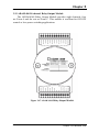
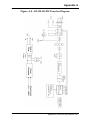
3.20 ADAM-4080/4080D Counter/Frequency Input Modules ….. 3-72
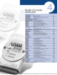
Chapter 4 Command Set ..................................................…......... 4-1
4.1 Introduction.................................................................….......... 4-2
4.2 Syntax .........................................................................….......... 4-2
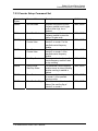
4.3 I/O Module Commands Search Table ......................….......... 4-4
Chapter 5 Analog Input Module Command Set ........….............. 5-1
5.1 Analog Input Command Set ................................……............
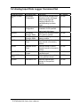
5.2 Analog Input Data Logger Command Set ............….….........
5.3 Digital I/O, Alarm and Event Command Set ......……….........
5.4 Excitation Voltage Output Command Set ............……..........
5-2
5-34
5-47
5-61
Chapter 6 AO commands..................................................…......... 6-1
6.1 Analog Output Module Command for ADAM-4021…............ 6-2
6.2 Analog Output Module Command for ADAM-4024...…......... 6-19
Chapter 7 Digital IO, Relay & Counter commands.........…......... 7-1
7.1 Configuration, Counter Input and Display Command Set ... 7-2
7.2 Counter/Frequency Module Command.................................. 7-28
7.2.1 Configuration, Counter Input and Display Command Set…... 7-28
7.2.2 Counter Setup Command Set................................................... 7-40
7.2.3 Digital Filter and Programmable Threshold Command Set….7-49
7.2.4 Digital Output and Alarm Command Set.................................. 7-60
Chapter 8 Calibration ...........................................…..................... 8-1
8.1 Analog Input Module Calibration ............................…........... 8-2
8.2 Analog Input Resistance Calibration .................................... 8-5
8.3 Analog Input Thermistor module Calibration ....................… 8-7
8.4 Analog Output Calibration ..................................................... 8-13
Appendix A Technical Specifications..............................…......... A-1
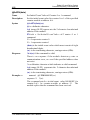
A.1 ADAM-4011 Thermocouple Input Module ................…......... A-2
A.2 ADAM-4011D Thermocouple Input Module with LED
Display .......................................................................……...... A-5
A.3 ADAM-4012 Analog Input Module ......................................... A-8
A.4 ADAM-4013 RTD Input Module ......................................….... A-10
A.5 ADAM-4016 Strain Gauge Input Module .....................…...... A-12
A.6 ADAM-4017/4017+ 8-Channel Analog Input Module ..…..... A-14
A.7 ADAM-4018/4018+ 8-channel Analog Input Module ...…..... A-16
A.8 ADAM-4018M 8-channel Analog Input Data Logger ....…... A-19
A.9 ADAM-4019+ 8-channel Universal Analog Input Module A-22
A.10 ADAM-4021/4024 Analog Output Module ........................... A-24
A.11 ADAM-4050 Digital I/O Module.................................…......... A-28
A.12 ADAM-4051/4052 Isolated Digital Input Module ................. A-30
A.13 ADAM-4053 16-channel Digital Input Module ............…..... A-32
A.14 ADAM-4055 16-channel Digital I/O Module ............…......... A-34
A.15 ADAM-4056S 12-channel Sink Type Isolated Digital Output
Module .......…………………………………………………...….. A-36
A.16 ADAM-4056SO 12-channel Source Type Isolated Digital Output
Module ........……………………………………………….…...... A-38
A.17 ADAM-4060 Relay Output Module........................................ A-40
A.18 ADAM-4068/4069 8-channel Relay Output Module ............ A-42
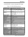
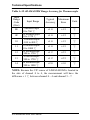
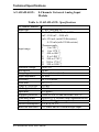
A.19 ADAM-4080 Counter/Frequency Input Module ................... A-44
A.20 ADAM-4080D Counter/Frequency Input Module with LED
Display …................................................................................ A-46
Appendix B Data Formats and I/O Ranges ..................…............ B-1
B.1 Analog Input Formats.............................................…............. B-2
B.1.1 Engineering Units .............................................................……..........
B.1.2 Percent of FSR .................................................................….............
B.1.3 Twos complement hexadecimal .....................................……............
B.1.4 Ohms ..............................................................................……............
B-2
B-3
B-4
B-5
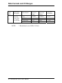
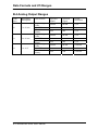
B.2 Analog Input Ranges.............................................….............. B-6
B.3 Analog Output Formats ..............................................…........ B-11
B.3.1 Engineering Units ............................................................………........ B-11
B.3.2 Percent of Span ........................................................…….................. B-11
B.3.3 Hexadecimal ............................................................………............... B-11
B.4 Analog Output Ranges .......................................…................ B-12
Appendix C Technical Diagrams .................................…............. C-1
C.1 ADAM Dimensions ..............................................…................ C-2
C.2 Installation .............................................................….............. C-3
C.2.1 DIN-Rail Mounting ......................................................…...….............. C-3
C.2.2 Panel Mounting .............................................................…….............. C-5
C.2.3 Piggyback Stack ....................................................….....…................. C-7
Appendix D Utility Software .................................…..................... D-1
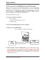
D.1 ADAM-4000 Utility Software ......................…......................... D-2
D.2 The procedure for ADAM-4000 series installation guide…..D-6
Appendix E RS-485 Network .............................…........................ E-1
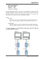
E.1 Basic Network Layout ................................…......................... E-3
E.2 Line Termination .........................................…........................ E-5
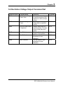
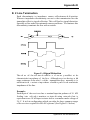
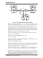
E.3 RS-485 Data Flow Control ..................................................... E-7
Appendix F How to use the Checksum feature ..........…............ F-1
F.1 Checksum Enable/Disable ......................................…............ F-2
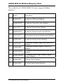
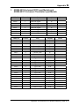
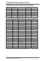
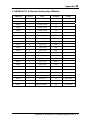
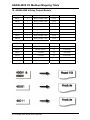
Appendix G ADAM-4000 I/O Modbus Mapping Table ....…......... G-1
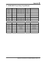
Appendix H Changing Configuration to Modbus Protocol ....... H-1
Introduction
1
Introduction
1.1 Overview
The ADAM Series is a set o
f in telligent sen sor-to-computer
interface m odules containi ng built-in microprocessor. They are
remotely controlled through a simple set of commands issued in ASCII
format and t ransmitted i n RS-485 protocol. T hey provide si gnal
conditioning, isolation, r anging, A/ D a nd D/A co nversion, data
comparison, a nd digital c ommunication functions. S ome m odules
provide digital I/O lines for controlling relays and TTL devices.
Software Configuration and Calibration
By merely issu ing a co mmand fro m th e ho st co mputer, you can
change an analog input module to accept several ranges of voltage input,
thermocouple in put o r RTD in put. All of th e m odule’s co nfiguration
parameters i ncluding I/ O ad dress, com munication s peed, HI a nd LO
alarm, calib ration p arameters settin gs m ay b e set remotely. Re mote
configuration can be do ne by usi ng either the p rovided menu-based
software or the command set’s configuration and calibration commands.
By sto ring con figuration and calibratio n parameters in a no nvolatile
EEPROM, modules are able to retain these parameters in case of power
failure.
Watchdog Timer
A watchdog timer sup ervisory function will au tomatically reset the
ADAM m odules in th e ev ent of system failu re. Main tenance is thu s
simplified.
Power Requirements
Although t he m odules ar e de signed for st andard industrial
unregulated 2 4 VDC power supply, they a ccept any power unit that
supplies power within the range of +10 to +3 0 VDC. The power supply
ripple m ust be l imited t o 5 V peak-to-peak, a nd t he i mmediate ri pple
voltage should be maintained between +10 and +30 VDC.
Connectivity and Programming
ADAM m odules can c onnect t o an d c ommunicate with al l com puters
and term inals. They
use RS-485 tra nsmission standa rds, a nd
communicate with ASCII format co mmands. T he com mand set for
every module type consists of approximately ten different commands.
1-2 ADAM 4000 Series User’s Manual
Chapter 1
The command set for input modules is larger because it incorporates
alarm funct ions. All com munications t o and from t he m odule are
performed i n ASC II, which m eans t hat A DAM m odules ca n be
virtually programmed in any high-level language.
RS-485 Network
The RS-4 85 network provides l ower-noise sensor readings, as
modules can be placed m uch closer to the source. Up to 256 ADAM
modules may be connected to an RS-485 multi-drop network by using
the ADAM RS-485 re
peater which ex tends the
maximum
communication distance up to 4,000 ft. The host computer is connected
to the RS-485 network with one of its COM ports through the ADAM452x module (RS-232 to RS-422/485 converter).
To boost the network’s throughput, ADAM RS-485 repeater uses a
logical R TS si gnal t o m anage t he re peater’s di rection. The o nly t wo
wires that are needed for the RS-485 network, DATA+ and DATA-, are
inexpensive shielded twisted pair.
Panel/DIN Rail mounting
Chapter 1 Introduction 1-3
Introduction
ADAM m odules can be m ounted on a ny p anels, brackets, o r D IN
rails. They can also be stacked together.
The RS-485 network, together with screw-terminal plug connectors,
allows for sy stem expan sion, reconfiguration, a nd re pair wi thout
disturbing field wiring.
Protection against the environment
Since all th e co nfigurations are con trolled b y so ftware, th e
protection p rovided by t he packaging i s very i mportant. The pl astic
outer shell enh ances resistan ce ag ainst corro sive m aterials, m oistures
and vibrations. ADAM modules’ low power requ irements help them to
operate in temperatures from 0 to 70 ℃, and in humidity from 0 to 95%
(non-condensing). Th ey are co mpactly bu ilt u sing au tomated SMT
technology. T herefore, t hey can be im plemented in water-tight and
explosion-proof industrial enclosures.
1.2 Applications
• Remote data acquisition
• Pr ocess monitoring
• Industrial process control
• Ener gy management
• Sup ervisory control
• Security systems
• Lab oratory automation
• Bu ilding automation
• Produ ct testing
• Di rect digital control
1-4 ADAM 4000 Series User’s Manual
Installation Guideline
2
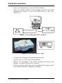
Installation Guideline
This chapter provides guidelines to what is needed to set up and
install an ADAM network. A quick hookup scheme is provided that lets
you configure modules before they are installed in a network. To help
you connect ADAM modules with sensor inputs, several wiring
examples are provided. At last, you will find a programming example
using the ADAM command set at the end of this chapter.
Be sure to plan the layout and configuration of your network
carefully before you start. Guidelines regarding layout are given in
Appendix E: RS-485 Network.
2.1 System Requirements to set up an ADAM network
The following list gives an overview of what is needed to setup,
install and configure an ADAM environment.
• ADAM modules
• A host computer, such as an IBM PC/AT compatible, that can
output ASCII characters with a RS-232C or RS-485 port.
• Power supply for the ADAM modules (+10 to +30 VDC )
• ADAM Series Utility software
• ADAM Isolated RS-232/RS-485 Converter (optional)
• RS-232/RS-485 ADAM Repeater (optional)
Host computer
Any computer or terminal that can output in ASCII format over
either RS-232 or RS-485 can be connected as the host computer. When
only RS-232 is available, an ADAM RS-232/RS-485 Converter is
required to transform the host signals to the correct RS-485 protocol.
The converter also provides opto-isolation and transformer-based
isolation to protect your equipment.
2-2 ADAM 4000 Series User’s Manual
Chapter 2
Power supply
For the ease of use in industrial environments, the ADAM modules
are designed to accept industry standard +24 VDC, unregulated power.
Operation is guaranteed when using any power supply between +10 and
+30 VDC . Power ripples must be limited to 5 V peak to peak while the
voltage in all cases must be maintained between +10 and +30 VDC . All
power supply specifications are referenced at module connector. When
modules are powered remotely, the effects of DC voltage drops must be
considered.
All modules use on-board switching regulators to sustain good
efficiency over the 10 to 30 V input range; therefore, we can assume
that the actual drawn current is inversely proportional to the DC voltage.
The following example shows how to calculate the required current that
a power supply should provide.
Assume that a +24 VDC is used for five ADAM-4011 Analog Input
Modules, and the distance between modules and power supply is not
significant enough to cause a DC voltage drop. One ADAM-4011
module consumes a maximum of 1.2 Watts (W). The total required
power will equal to 5 x 1.2=6 W. A power supply of +24 VDC should
therefore be able to supply a minimal current of 6 / 24=0.25 Amps.
Small systems may be powered by using wall-mounted modular
power supplies. Also, when modules operate in long communication
lines (>500 feet), it is often more reliable to obtain power locally
through modular power supplies. These inexpensive units can be easily
obtained from any electronic retail stores.
The power cables should be selected according to the length of the
power lines and the number of modules connected. When implementing
a network with long cables, the use of thicker wire is more suitable due
to the limitation of DC voltage drop. Furthermore, long wires can also
cause interference with communication wires.
Chapter 2 installation Guideline 2-3
Installation Guideline
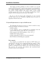
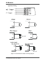
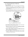
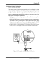
Figure 2-1 Power Supply Connections
We advise the following standard colors (as indicated on the
modules) for each power line:
+Vs
(R)
Red
GND
(B)
Black
Communication Wiring
We recommend the use of shielded-twisted-pair cable in the ADAM
network for reducing interference purpose, but the cable has to comply
with the EIA RS-485 standard. Furthermore, only one set of twistedpair cable is required for transmitting Data. We advise the following
standard colors (as indicated on the modules) for each the
communication line:
DATA+ (Y)
Yellow
DATA- (G)
Green
ADAM Utility Software
A menu-driven utility program is provided for ADAM module
configuration, monitoring and, calibration. It also includes a terminal
emulation program that lets you communicate through the ADAM
command set. (See Appendix D, Utility Software and online help)
2-4 ADAM 4000 Series User’s Manual
Chapter 2
Notice: User can refer our help file to see more details for explanation of
Utility operation.
ADAM Communication Speed
In ADAM series, the baud rate can be configured from 1200 bps to
38.4 Kbps. However, the baud rate of all modules in an RS-485
network must be the same.
ADAM Isolated RS-232/RS485 Converter (optional): ADAM-452x
When the host computer or terminal only has a RS-232 port, an
ADAM Isolated RS-232/RS-485 Converter is required. Since this
module is not addressable by the host, the baud rate must be reset using
a switch inside the module. The factory default setting is 9600 baud.
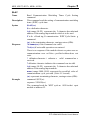
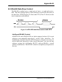
ADAM Repeater (optional): ADAM-451x
When communication lines exceed 4000 ft (1200 meter) or more
than 32 ADAM modules are connected, a repeater should be
implemented. In a network, up to eight Repeater modules can be
connected allowing connection up to 255 ADAM modules. As with the
Converter module, the Repeater module is not addressable by the host
and the baud rate must be reset by changing the switch inside the
module. The factory default setting is 9600 baud.
Chapter 2 installation Guideline 2-5
Installation Guideline
2.2 Basic configuration and hook-up
Before placing a module in an existing network, the module should
be configured. Though all modules are initially configured at the
factory, it is recommended to check if the baud rate is set correctly
beforehand.
Default Factory Settings
Baud rate: 9600 Bit/sec.
Address: 01 (hexadecimal)
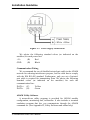
The basic hook-up for module configuration is shown below.
Figure 2-2 Basic Hook-up of ADAM Module to Host Switches
2-6 ADAM 4000 Series User’s Manual
Chapter 2
The following items are required to configure a module: an ADAM
converter module, a personal computer with RS-232 port (baud rate set
to 9600) and the ADAM utility software.
Configuration with the ADAM Utility Software
The easiest way to configure the ADAM module is by using the
ADAM utility software. It is a user friendly structured menu program
that will guide you through every step of the configuration. (See
Appendix D, Utility Software)
Changing the protocol from ADAM ASCII to Modbus
Some ADAM-4000 modules support both ADAM ASCII and
Modbus protocols, and the factory default setting of these modules is
ADAM ASCII protocol. If you would like to configure the modules to
Modbus protocol, please refer to Appendix H which describes how to
change the protocol in ADAM utility.
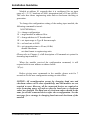
Configuration with the ADAM command set
ADAM modules can also be configured by issuing direct commands
through a terminal emulation program that is part of the ADAM utility
software. The following example will guide you through the setup of an
analog input module. Assume an ADAM-4011 Analog Input module
still has its default settings (baud rate 9600 and address 01h), and you
are being requested to send its default settings before any
reconfiguration is made.
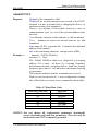
NOTICE: An analog input module requires a maximum of 7 seconds
to perform auto calibration and ranging after reboot or start up.
During this time span, the module can not be addressed to perform
any other actions.
Example:
Make sure that the module is properly connected and turn on all the
connected devices. Then, start the terminal emulation program, and
type in the following command:
$012(cr)
The command above requests the module with address 01 to send its
configuration status
!01050600
Chapter 2 installation Guideline 2-7
Installation Guideline
Module at address 01 responds that it is configured for an input
range of +/-2.5 V, baud rate of 9600, integration time of 50 ms (60 Hz).
The code also shows engineering units and no checksum checking or
generation.
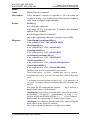
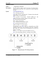
To change the configuration setting of the analog input module, the
following command is issued:
%01070F0600(cr)
% = change configuration
01 = target module at address 00 to:
07 = change address to 07 hexadecimal
0F = set input range to Type K thermocouple
06 = set baud rate to 9600
00 = set integration time to 50 ms (60 Hz)
disable checksum
set data format to engineering units
(Please refer to Chapter 4, a full description of Command set syntax for
an analog input module)
When the module received the configuration command, it will
respond with its new address as shown below:
!07(cr)
Before giving more commands to the module, please wait for 7
seconds to let the new configuration settings to take effect.
NOTICE: All reconfiguration except for changing baud rate and
checksum values can be done dynamically, and the modules are not
required to reset. However, all the connected devices are required to
reset by turning power off and on after the baud rate or checksum
values are changed. The baud rate or checksum values should be the
same for all the connected devices after the reconfiguration. See the
next page for a strategy in changing baud rate and checksum of the
network.
2-8 ADAM 4000 Series User’s Manual
Chapter 2
2.3 Baud rate and Checksum
ADAM modules contain EEPROMs to store configuration
information and calibration constants. The EEPROM replaces the
conventional array of switches and pots that are originally used for
specifying baud rate, input and output range… etc.
Since there is no visual indication of a module’s configuration status,
it is impossible to know the baud rate, address and other settings just by
looking at it. It might not be possible to establish communications with
a module whose baud rate and address are unknown. To overcome this
problem, most modules have an input terminal labeled INIT*. Booting
the module while connecting the INIT* terminal with the module’s
GND terminal forces the configuration into a known state called the
INIT* state. Besides, some newer modules have INIT switch which you
can set “Init” or “Normal” (See Figure 2.4). If you set the switch to
“Init”, then it becomes INIT* state.
INIT* state defaults:
Baud rate: 9600
Address: 00h
Checksum: disabled
Forcing the module in INIT* state does not change any parameters
in the module’s EEPROM. When the module is in the INIT* state with
its INIT* and GND terminals shorted, all configuration settings can be
changed, and the module will respond to all other commands normally.
Changing Baud rate and Checksum
Baud rate and checksum settings have several things in common:
• They should be the same for all modules and host computer.
• Their settings can only be changed by putting a module in the INIT*
state.
• Changed settings can only take effect after a module is rebooted
To alter baud rate or checksum settings, you must perform the
following steps:
Chapter 2 installation Guideline 2-9
Installation Guideline
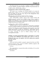
• Power on all components except the ADAM Module.
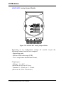
• Power the ADAM module on while shorting the INIT* and GND
terminals (See Figure 2-3) or set the INIT switch to “Init” (See
Figure 2-4)
Figure 2-3 Grounding the INIT* Terminal
Figure 2-4 Set INIT switch to “Init”
• Configure the checksum status and/or the baud rate.
• Switch the power OFF to the ADAM Module.
• Remove the grounding of the INIT* terminal and turn on the
module, or set the INIT switch to “Normal”.
• Check the settings (If the baud rate has changed, the settings on the
host computer should be changed accordingly).
2-10 ADAM 4000 Series User’s Manual
Chapter 2
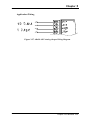
2.4 Multiple Module Hookup
The Figure below is an example of how ADAM modules are connected
in a multiple module network:
Figure 2-5 Multi-module Connection
Chapter 2 installation Guideline 2-11
Installation Guideline
2.5 Programming Example
The following example is a simple program written in Visual Basic 6.0
that demonstrates how to get temperature reading which is stored in the
address of 01H from ADAM-4011 module.
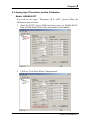
Step 1. Using ADAM Utility to check the settings as the following below:
“Address = 01H”, “Baud rate = 9600” and “Checksum = Disabled”.
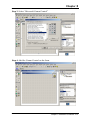
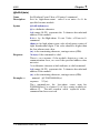
Step 2. Run VB 6.0 and add a control via “Project\Component”.
2-12 ADAM 4000 Series User’s Manual
Chapter 2
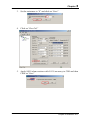
Step 3. Select “Microsoft Comm Control”
Step 4. Add the Comm Control on the form.
Chapter 2 installation Guideline 2-13
Installation Guideline
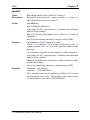
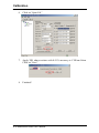
Step 5. Add three Command Buttons on the form as shown below
Step 6. Add one Label and one Text on the form as shown below.
2-14 ADAM 4000 Series User’s Manual
Chapter 2
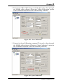
Step 7. Click OPEN Button and type in the following codes. The source
codes are listed at the end of this section.
Step 8. Click SEND Button and type in the following codes. The source
codes are listed at the end of this section.
Chapter 2 installation Guideline 2-15
Installation Guideline
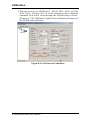
Step 9. Click CLOSE Button and type in the following codes. The source
codes are listed at the end of this section.
Step 10. Run the Project → Click OPEN to open COM1 → Click SEND to
send the Get Temperature Reading Command. Now, you will find the
reading the same as the displayed format shown below.
2-16 ADAM 4000 Series User’s Manual
Chapter 2
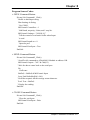
Program Source Codes:
OPEN Command Button:
Private Sub Command1_Click()
' Buffer to hold input string
Dim Instring As String
' Use COM1.
MSComm1.CommPort = 1
' 9600 baud, no parity, 8 data, and 1 stop bit.
MSComm1.Settings = "9600,N,8,1"
' Tell the control to read entire buffer when Input
' is used.
MSComm1.InputLen = 0
' Open the port.
MSComm1.PortOpen = True
End Sub
SEND Command Button:
Private Sub Command2_Click()
' Send Get AI command to ADAM-4011 Module at address 01H.
MSComm1.Output = "#01" & Chr$(13)
' Wait for data to come back to the serial port.
Do
DoEvents
Buffer$ = Buffer$ & MSComm1.Input
Loop Until InStr(Buffer$, vbCr)
' Read the response till the carriage return character.
Text1.Text = Buffer$
' Display the reading.
End Sub
CLOSE Command Button
Private Sub Command3_Click()
' Close the serial port.
MSComm1.PortOpen = False
End Sub
Chapter 2 installation Guideline 2-17
I/O Modules
3
I/O Modules
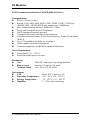
3.0 The common specification of ADAM-4000 I/O Series
Communication:
z
RS-485 (2-wire) to host
z
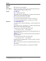
Speeds: 1200, 2400, 4800, 9600, 19200, 38400, 57600, 115200 bps
(ADAM-4080, ADAM-4080D only support up to 38400 bps)
z
Max. communication distance: 4000 feet (1.2 km)
z
Power and communication LED indicator
z
ASCII command/response protocol
z
Communication error checking with checksum
z
Asynchronous data format: 1 start bit, 8 data bits, 1 stop bit, no parity
(N, 8, 1)
z
Up to 256 multidrop modules per serial port
z
Online module insertion and removal
z
Transient suppression on RS-485 communication lines
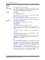
Power Requirement:
z
Unregulated +10 ~ +30 VDC
z
Protected against power reversal
Mechanical:
z
Case
z
Plug-in screw
Terminal block
ABS+PC with captive mounting hardware
Accepts 0.5 mm2 to 2.5 mm2,
#14 ~22 or #14~28 AWG
Environment
z
EMI
z
Operating Temperature
z
Storage Temperature
z
Humidity
3-2 ADAM 4000 Series User’s Manual
Meets FCC Class A or CE
-10 ~ 70° C (14 ~ 158° F)
-25 ~ 85° C (-13 ~ 185° F)
5 ~ 95%, non-condensing
Chapter 3
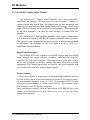
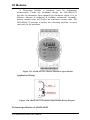
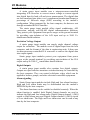
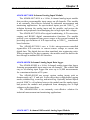
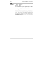
3.1 ADAM-4011/4011D Thermocouple Input Modules
The ADAM-4011/4011D Thermocouple Input Modules use a
microprocessor-controlled integrating A/D converter to convert sensor
voltage, current or thermocouple signal into digital data. The digital
data is then translated into either two’s complement hexadecimal
format or percentage of full-scale range (FSR) according to the
module’s configuration. When prompted by the host computer, the data
is sent through a standard RS-485 interface.
The ADAM-4011/4011D Thermocouple Input Modules offer signal
conditioning, A/D conversion, ranging, and RS-485 digital
communication functions. They protect your equipment from power
surges at the ground terminal by providing opto-isolation of the A/D
input and transformer based isolation up to 3000 VDC. (ADAM-4011
has transformer-based isolation up to 500 VDC)
Open Thermocouple Detection and Input Surge Protection
(ADAM-4011D only)
The ADAM-4011D provides an open thermocouple detection
function. Users can use a simple command to detect whether the
thermocouple is opened or closed. The module also provides surge
protection on its input channel. Internal high-speed transient suppressor
on its input channel protects the module from dangerous spikes and
voltages.
Front Panel LED Indicator (ADAM-4011D only)
The 4½ digits LED display on the back of the ADAM-4011D lets
you monitor the process readings right at their source. The module
displays readings in a wide variety of formats as well as high-low alarm
messages. The ADAM-4011D offers flexibility, easy installation, and
direct availability of process data. For critical process monitoring, this
module is the ideal choice.
Digital Input/Output
The ADAM-4011/4011D Thermocouple Input Modules also contain
two digital outputs and one digital input. Outputs are open-collector
transistor switches that may be controlled by the host computer. They
can control solid-state relays, which may be used to control heaters,
pumps, and other electrical powered equipment. The digital inputs may
be read by the host computer and used to sense the state of a remote
digital signal.
Chapter 3 I/O Modules 3-3
I/O Modules
Event counting
The event counter is connected to the Digital Input channel and can
be used to keep track of the total amount of external low-speed pulses.
Its accumulated maximal count is 65535. The count will maintain at
65535 even if the actual number of events exceeds 65535. The counter
can be read or reset to zero by the host computer.
Since the Event counter’s data are not stored in EEPROM, the event
counter is cleared and set to zero after every reset or start up of the
analog input module.
Alarm signaling
Analog input modules include High and Low alarm functions. High
and Low alarm limits may be downloaded into the module’s EEPROM
by the host computer.
The alarm functions can be enabled or disabled remotely. When the
alarm function is enabled, both Digital Output channels are used to
indicate the High and Low alarm state. Digital Output channel 1 (DO1)
equals to High alarm state, and Digital Output channel 0 (DO0) equals
to Low alarm state. The High and Low alarm states can be read at any
time by the host computer.
Every A/D conversion will be followed by a comparison with the
High and Low limit. When the input value exceeds one of these limits,
the High or Low alarm state is set to ON.
There are two alarm mode options, Momentary and Latching. If the
alarm is in Latching mode, the alarm will stay on even if the input value
returns within the limits. An alarm in Latching mode can be turned OFF
by giving a Clear Alarm command from the host computer. A Latching
alarm is cleared by the module when the opposite alarm is set. When
the module receives a value that is lower than the Low alarm limit, it
will clear the High alarm and turn the Low alarm ON.
When the alarm is in Momentary mode, the alarm will be turned
OFF as soon as the input value returns within the limits.
The arrangement of coupling High and Low alarm states with
Digital Output lines may be utilized to build ON/OFF controllers that
can operate without the involvement of host computer.
3-4 ADAM 4000 Series User’s Manual
Chapter 3
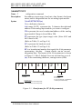
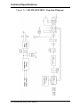
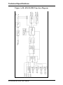
Function Description for the ADAM-4011 Thermocouple Input
Module
To provide a better understanding of the ADAM module functions,
the following is a description of the module ADAM-4011 with the most
extensive set of functions.
All analog input data first flow through the PGA (programmable
gain amplifier). The amplifier can vary its gain from 1 to 128. The PGA
then automatically adjusts the signal to a range from -2.5 V to +2.5 V.
This ensures an optimal input voltage and resolution for the A/D
converter.
The A/D conversion is supervised by the microprocessor that holds
the calibration software. Two kinds of calibrations, Auto Zero and Auto
Span calibrations, take place automatically in startup or reset. Normal
calibration is used to adjust the signal according to calibration
parameters defined by the user.
The digital 10 Hz filter provides a steady state output by using the
Δ function.
Before the data enter the microprocessor, they pass through an
optical isolation device which prevents the chance of circuit damaging
caused by power surges from the ground terminal.
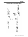
The microprocessor has six basic functions:
- Linearization of T/C (Thermocouple)
- Communication software and command set
- Calibration software
- Alarm monitoring
- Event counting
- Management of the EEPROM device that holds the system parameters
- Data transformation
After data have been transformed to the right data format, they are
being passed on to the RS-485 output port.
If an input value exceeds the High alarm setting or falls below the
Low alarm setting, a flag is set in one of the Digital Output channels.
Finally, the on-board switching regulator accepts voltage between +10
and +30 VDC, and it has an isolation value of 500 VDC to protect your
equipment from damages caused by power surges.
Chapter 3 I/O Modules 3-5
I/O Modules
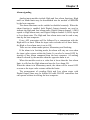
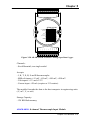
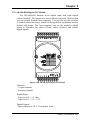
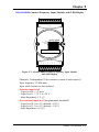
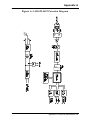
ADAM-4011 Thermocouple Input Module
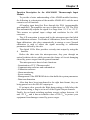
Figure 3-1 ADAM-4011 Thermocouple Input Module
Accepts:
- J, K, T, E, R, S and B thermocouples
- Millivolt inputs: ±15 mV, ±50 mV, ±100 mV and ±500 mV
- Volt inputs: ±1 V and ±2.5 V
- Current input: ±20 mA (Requires a 125 resistor)
Two digital output channels and one digital input channel are provided.
Depending on the module’s configuration setting, it can forward the
data to the host computer in one of the following formats:
- Engineering units (o C, mV, V or mA)
- Percent of full-scale range (FSR)
- Two’s complement hexadecimal
3-6 ADAM 4000 Series User’s Manual
Chapter 3
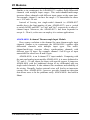
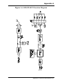
ADAM-4011D Thermocouple Input Module
Figure 3-2 ADAM-4011D Thermocouple Input Module with LED Display
Accepts:
- J, K, T, E, R, S and B thermocouples
- Millivolt inputs: ±15 mV, ±50 mV, ±100 mV and ±500 mV
- Volt inputs: ±1 V and ±2.5 V
- Current input: ±20 mA (Requires a 125 resistor)
Two digital output channels and one digital input channel are provided.
Depending on the module’s configuration setting, it can forward the
data to the host computer in one of the following formats:
- Engineering units (oC, mV, V, or mA)
- Percent of full-scale range (FSR)
- Two’s complement hexadecimal
Chapter 3 I/O Modules 3-7
I/O Modules
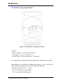
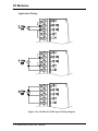
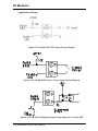
Application Wiring
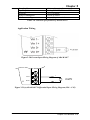
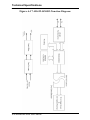
Figure 3-3 ADAM-4011/4011D Thermocouple Input Wiring Diagram
Figure 3-4 ADAM-4011/4011D Millivolt and Volt Input Wiring Diagram
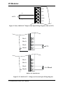
Figure 3-5 ADAM-4011/4011D Process Current Input Wiring Diagram
3-8 ADAM 4000 Series User’s Manual
Chapter 3
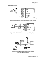
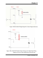
Figure 3-6 ADAM-4011/4011D Digital Output Wiring Diagram
Used with SSR (HI-LO alarm)
Figure 3-7 ADAM-4011/4011D Digital Input Wiring Diagram
Used with TTL
Figure 3-8 ADAM-4011/4011D Digital Input Wiring Diagram
Used with Dry contact
Chapter 3 I/O Modules 3-9
I/O Modules
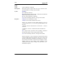
3.2 ADAM-4012 Analog Input Module
The ADAM-4012 Analog Input Modules use a microprocessorcontrolled integrating A/D converter to convert sensor voltage or
current signals into digital data. The digital data are then translated into
either two’s complement hexadecimal format or percentage of full-scale
range (FSR) according to the module’s configuration. When prompted
by the host computer, the data are sent through a standard RS-485
interface.
The ADAM-4012 Analog Input Modules offer signal conditioning,
A/D conversion, ranging, and RS-485 digital communication functions.
They protect your equipment from power surges at the ground terminal
by providing opto-isolation of the A/D input and up to 3000 VDC
transformer based isolation.
Digital Inputs/Outputs
The ADAM-4012 also contains two digital outputs and one digital
input. Outputs are open-collector transistor switches that may be
controlled by the host computer. They can control solid-state relays,
which can be applied to heaters, pumps, and other electrical powered
equipment. The digital inputs may be read by the host computer and
used to sense the state of a remote digital signal.
Event counting
The event counter is connected to the Digital Input channel and can
be used to keep track of the total amount of external low-speed pulses.
Its accumulated maximal count is 65535. The number 65535 is held
even if the actual number of events exceeds 65535. The counter can be
read or reset to zero by the host computer.
Since the Event counter’s data are not stored in EEPROM, the event
counter is cleared and set to zero after every reset or start up of the
analog input module.
3-10 ADAM 4000 Series User’s Manual
Chapter 3
Alarm signaling
Analog input modules include High and Low alarm functions. High
and Low alarm limits may be downloaded into the module’s EEPROM
by the host computer.
The alarm functions can be enabled or disabled remotely. When the
alarm function is enabled, both Digital Output channels are used to
indicate the High and Low alarm states. Digital Output channel 1 (DO1)
equals to High alarm state, and Digital Output channel 0 (DO0) equals
to Low alarm state. The High and Low alarm states can be read at any
time by the host computer.
Every A/D conversion will be followed by a comparison with the
High and Low limit. When the input value exceeds one of these limits,
the High or Low alarm state is set to ON.
There are two alarm mode options, Momentary and Latching.
If the alarm is in Latching mode, the alarm will stay on even when
the input value returns within the limits. It can also be turned OFF by
issuing a Clear Alarm command from the host computer. A Latching
alarm is cleared by the module when the opposite alarm is set.
When the module receives a value that is lower than the Low alarm
limit, it will clear the High alarm and turn the Low alarm ON.
When the alarm is in Momentary mode, the alarm will be turned OFF
as soon as the input value returns within the limits.
The arrangement of coupling High and Low alarm states with
Digital Output lines may be utilized to build ON/OFF controllers that
can operate without involving the host computer.
Chapter 3 I/O Modules 3-11
I/O Modules
ADAM-4012 Analog Input Module
Figure 3-9 ADAM-4012 Analog Input Module
Accepts:
- Millivolt inputs ± 150 mV and ±500 mV
- Volt inputs: ±1 V, ±5 V and ±10 V
- Current input: ±20 mA (requires a 125 resistor)
Two digital output channels and one digital input channel are provided.
Depending on the module's configuration setting, it can forward the
data to the host computer in one of the following formats:
- Engineering units (mV, V, or mA)
- Percent of full-scale range (FSR)
- Two’s complement hexadecimal
3-12 ADAM 4000 Series User’s Manual
Chapter 3
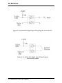
Application Wiring
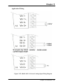
Figure 3-10 ADAM-4012 Millivolt and Volt Input Wiring Diagram
Figure 3-11 ADAM-4012 Process Current Input Wiring Diagram
Figure 3-12 ADAM-4012 Digital Output Wiring Diagram
Used with SSR (HI-LO alarm)
Chapter 3 I/O Modules 3-13
I/O Modules
Figure 3-13 ADAM-4012 Digital Input Wiring Diagram Used with TTL
Figure 3-14 ADAM-4012 Digital Input Wiring Diagram
Used with Dry contact
3-14 ADAM 4000 Series User’s Manual
Chapter 3
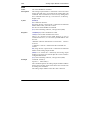
3.3 ADAM-4013 RTD Module
The ADAM-4013 RTD Input Module supports one Pt or Ni RTD
input channel for temperature measurement. This module can accept
RTD sensors with two, three, or four wires. The module offers signal
conditioning, A/D conversion, ranging, and RS-485 digital
communication functions. It protects your equipment from power
surges at the ground terminal by providing opto-isolation of the A/D
input and up to 3000 VDC transformer based isolation.
Figure 3-15 ADAM-4013 RTD Input Module
Accepts:
- Input from platinum and nickel RTDs
Depending on the module’s configuration setting, it can forward the
data to the host computer in one of the following formats:
- Engineering units (°C)
- Percent of full-scale range (FSR)
- Two’s complement hexadecimal
Chapter 3 I/O Modules 3-15
I/O Modules
Application Wiring
Figure 3-16 ADAM-4013 RTD Inputs Wiring Diagram
3-16 ADAM 4000 Series User’s Manual
Chapter 3
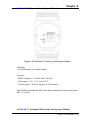
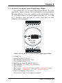
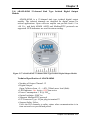
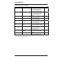
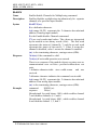
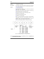
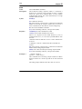
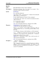
3.4 ADAM-4015 6-channel RTD Input Module
A RTD module is popularly used for temperature measurement.
Unlike the traditional design, the ADAM-4015 RTD Input Module
provides six RTD input channels for different types of RTD signal like
as Pt, Ni, Balco. It is an effective solution in industrial & building
automation. Normally, broken external wire will lead to an inaccurate
current value; however, the ADAM-4015 provides a broken wire
detecting function. Therefore, users can easily fix the broken wire
problems. This module can accept RTD sensors that have two or three
wires. After the V2.04 of ADAM-4015, ADAM-4015 can support the
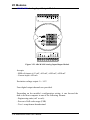
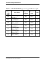
“BA1 -200~600℃”
14 RTD0+
RTD0(R) +Vs
(G)DATA-
N/A
RANGE
-50蚓 - 150蚓
0蚓 - 100蚓
0蚓 - 200蚓
0蚓 - 400蚓
-200蚓 - 200蚓
-40蚓 - 160蚓
-30蚓 - 120蚓
-80蚓 - 100蚓
0蚓 - 100蚓
(Y) DATA+
INIT*
N/A
Pt 100
Pt 1000
BALCO 500
Ni
Ni
RTD5+
TYPE
RTD5-
COM 5
RTD4+
CODE
(IEC/JIS) 30/35
(IEC/JIS) 30/35
(IEC/JIS) 30/35
(IEC/JIS) 30/35
(IEC/JIS) 30/35
40
41
42
43
(B) GND13
RTD1-
RTD1+
COM 0
COM 1
RTD2-
RTD2+
COM 2
RTD3-
RTD3+
GND
COM 4 1
RTD4-
26
COM 3
Please be noted that the pin 26 is defined as GND and it’s reserved.
Figure 3-17 ADAM-4015 6-channel RTD Input Module
Chapter 3 I/O Modules 3-17
I/O Modules
Application Wiring
Figure 3-18 ADAM-4015 RTD Input Module Wiring Diagram
3-18 ADAM 4000 Series User’s Manual
Chapter 3
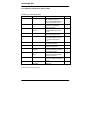
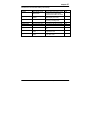
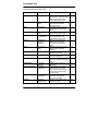
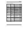
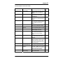
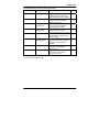
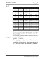
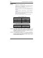
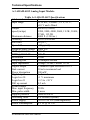
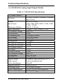
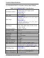
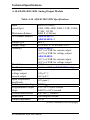
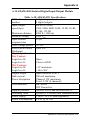
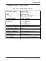
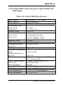
Technical specification of ADAM-4015
6 differential
Channel Number
Support Protocol
ADAM ASCII and MODBUS/RTU
Input Type
Pt100, Pt1000, BALCO500, Ni
Input Connections
2 or 3 wires
Wire Burnout Detection
Yes
Pt100: -50 to 150° C
0 to 100° C
0 to 200° C
0 to 400° C
-200 to 200° C
Input Type and
Temperature Range
Pt1000: -40 to 160° C
Balco500: -30 to 120° C
Ni 50 RTD: -80 to 100° C
Isolation Voltage
Ni 508 RTD: 0 to 100° C
3000 VDC
Sampling Rate
10 sample/second (total)
Input Impedance
10 MΩ
Resolution
16-bit
Accuracy
±0.1% or better
CMR@50/60Hz
120 dB
NMR@50/60Hz
100 dB
Span Drift
± 25 ppm/℃
Zero Drift
± 3 μV/℃
Watchdog Timer
System (1.6 second) and Communication
Power Input
+10~+30 VDC (non-regulated)
Power Consumption
1.2 W @ 24VDC
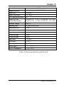
Table 3-1 Technical specification of ADAM-4015
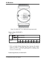
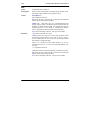
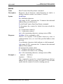
3.5 ADAM-4015T 6-channel Thermistor Input Module
Chapter 3 I/O Modules 3-19
I/O Modules
A Thermistor Module is popularly used for temperature
measurement. Unlike the traditional design, the ADAM-4015T
provides six thermistor input channels for thermistor signal. It is an
effective solution in industrial & building automation. Normally,
broken external wires will lead to an inaccurate current value. The
ADAM-4015T provides a broken wire detecting function, so users
can easily fix the problems.
Figure 3-19 ADAM-4015T 6-channel Thermistor Input Module
Application Wiring
Figure 3-20 ADAM-4015T Thermistor Input Module Wiring Diagram
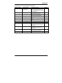
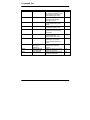
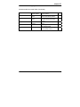
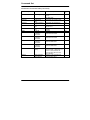
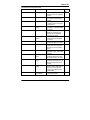
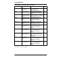
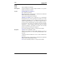
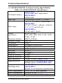
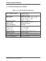
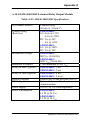
Technical specification of ADAM-4015T
3-20 ADAM 4000 Series User’s Manual
Chapter 3
6 differential
Channel Number
Support Protocol
ADAM ASCII and MODBUS/RTU
Input Type
Thermistor
Input Connections
2 or 3 wires
Wire Burnout Detection
Yes
Input Type and
Temperature Range
Thermistor 3k
Thermistor 10k
Isolation Voltage
3000 VDC
Sampling Rate
10 sample/second (total)
Input Impedance
10 MΩ
Resolution
16-bit
Accuracy
±0.1% or better
CMR@50/60Hz
120 dB
NMR@50/60Hz
100 dB
Span Drift
± 25 ppm/℃
Zero Drift
± 3 μV/℃
Watchdog Timer
System (1.6 second) and Communication
Power Input
+10~+30 VDC (non-regulated)
Power Consumption
1.2 W @ 24VDC
0~100℃ (9.796K ohm ~ 203.8 ohm)
0~100℃(29.49K ohm ~ 816.8 ohm)
Table 3-2 Technical specification of ADAM-4015T
Chapter 3 I/O Modules 3-21
I/O Modules
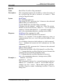
3.6 ADAM-4016 Analog Input/Output Module
A strain gauge input module uses a microprocessor-controlled
integrating A/D converter to convert sensor voltage or current signals
into digital data for load cell and stress measurement. The digital data
are then translated into either, two’s complement hexadecimal format or
percentage of full-scale range (FSR) according to the module’s
configuration. When prompted by the host computer, the data are sent
through a standard RS-485 interface.
The strain gauge input module offers signal conditioning, A/D
conversion, ranging, and RS-485 digital communication functions.
They protect your equipment from power surges at the ground terminal
by providing opto-isolation of the A/D input and up to 3000 VDC
transformer based isolation.
Excitation Voltage Output
A strain gauge input module can supply single channel voltage
output for excitation. The module receives digital input from the host
computer, and the format of the data is engineering units. It then uses
its microprocessor-controlled D/A converter to convert the digital data
into output signals.
Strain gauge input modules protect your equipment from power
surges at the ground terminal by providing opto-isolation of the D/A
output and up to 3000 VDC transformer-based isolation.
Digital Outputs
A strain gauge input module also contains four digital outputs.
Outputs are open-collector transistor switches that may be controlled by
the host computer. They can control solid-state relays which can be
applied to heaters, pumps, and other electrical controlled equipments.
Alarm signaling
Strain Gauge input modules include High and Low alarm functions.
High and Low alarm limits may be downloaded into the module’s
EEPROM by the host computer.
The alarm functions can be enabled or disabled remotely. When the
alarm function is enabled, both Digital Output channels are used to
indicate the High and Low alarm states. Digital Output channel 1 (DO1)
equals to High alarm state and Digital Output channel 0 (DO0) equals
to Low alarm state. The High and Low alarm state can be read at any
time by the host computer.
3-22 ADAM 4000 Series User’s Manual
Chapter 3
Every A/D conversion will be followed by a comparison with the
High and Low limits. When the input value exceeds one of these limits,
the High or Low alarm state is set to ON.
There are two alarm mode options, Momentary and Latching. If the
alarm is in Latching mode, the alarm will stay on even when the input
value returns within limits. An alarm in Latching mode can be turned
OFF by issuing a Clear Alarm command from the host computer. A
Latching alarm is cleared by the module when the opposite alarm is set.
When the module receives a value that is lower than the Low alarm
limit, it will clear the High alarm and turn the Low alarm ON.
When the alarm is in Momentary mode, the alarm will be turned
OFF as soon as the input value returns to within limits.
The arrangement of coupling High and Low alarm states with
Digital Output lines may be utilized to build ON/OFF controllers that
can operate without the host computer involvement.
Chapter 3 I/O Modules 3-23
I/O Modules
ADAM-4016 Analog Input/Output Module
Figure 3-21 ADAM-4016 Analog Input/Output Module
Accepts:
- Millivolt inputs: ±15 mV, ±50 mV, ±100 mV, ±500 mV
- Current input: ±20 mA
Excitation voltage output: 0 ~ 10 V
Four digital output channels are provided.
Depending on the module’s configuration setting, it can forward the
data to the host computer in one of the following formats:
- Engineering units (mV or mA)
- Percent of full-scale range (FSR)
- Two’s complement hexadecimal
3-24 ADAM 4000 Series User’s Manual
Chapter 3
Application Wiring
Figure 3-22 ADAM-4016 Strain Gauge Voltage Input Wiring Diagram
Figure 3-23 ADAM-4016 Strain Gauge Current Input Wiring Diagram
Chapter 3 I/O Modules 3-25
I/O Modules
Figure 3-24 ADAM-4016 Digital Output Wiring Diagram Used with SSR
3-26 ADAM 4000 Series User’s Manual
Chapter 3
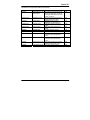
3.7 ADAM-4017/4017+/4018/4018M/4018+ 8-channel Analog Input Modules
ADAM-4017/4018 8-channel Analog Input Module
The ADAM-4017/4018 is a 16-bit, 8-channel analog input module
that provides programmable input ranges on all channels. This module
is an extremely cost-effective solution for industrial measurement and
monitoring applications. Its opto-isolated inputs provide 3000 VDC of
isolation between the analog input and the module, and protect the
module and peripherals from damaging due to high input-line voltages.
The ADAM-4017/4018 offers signal conditioning, A/D conversion,
ranging and RS-485 digital communication functions. The module
protects your equipment from power surges at the ground terminal by
providing opto-isolation of A/D input and up to 3000 VDC transformer
based isolation.
The ADAM-4017/4018 uses a 16-bit microprocessor-controlled
sigma-delta A/D converter to convert sensor voltage or current into
digital data. The digital data are then translated into engineering units.
When prompted by the host computer, the module sends the data to the
host through a standard RS-485 interface.
ADAM-4018M 8-channel Analog Input Data logger
The ADAM-4018M is a 16-bit, 8-channel analog input data logger
featuring programmable input ranges on all channels. This reliable and
easy to use analog input logger can store up to 38,000 measurements
for a maximum duration of 20 years.
The ADAM-4018M can accept various analog inputs such as
thermocouple, mV, V and mA. It also offers three configurable logging
modes, standard log, event log, and mixed log. Optically isolated inputs
provide 3000 VDC of isolation between the module and the analog input,
and protect the module and peripherals from damaging due to high
voltages on the input lines.
The ADAM-4018M is an extremely cost-effective solution for
industrial measurement and monitoring applications.
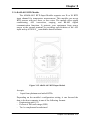
ADAM-4017+ 8-channel Differential Analog Input Module
Chapter 3 I/O Modules 3-27
I/O Modules
Here comes a solution to the demand for more analog input channels.
Similar to its counterpart, the ADAM-4017+ enables eight differential
channels with multiple input ranges. This multi-channel/multi-range
structure allows channels with different input ranges at the same time.
For example, channel 1 can have the range ± 5V meanwhile the others
are ± 10V and ± 20 mA.
Instead of leaving two single-ended channels in ADAM-4017
module due to the limit number of pins, ADAM-4017+ uses a switch
to switch AGND and INIT* to Vin6- and Vin7- respectively to allow 8channel input. Moreover, the ADAM-4017+ has been expanded to
accept 4 ~ 20 mA, so the user can employ it in various applications
ADAM-4018+ 8-channel Thermocouple Input Module
Here comes a solution to the demand for more thermocouple input
channels. Similar to its counterpart, the ADAM-4018+ enables eight
differential channels with multiple input types. This multichannel/multi-type structure allows synchronizing channels with
different types of input. For example, channel 1 has K type of input
meanwhile the others have R and S types.
ADAM-4018+ is an 8-channel T/C input module. Comparing with
the universal analog input module ADAM-4019, it is more dedicated to
T/C and 4 ~ 20 mA inputs for those with special request. It improves
ADAM-4018 with the traditional design of six differential and two
single-ended channels. It also enhances the steadiness and reliability of
the wiring. Normally, broken external wires will lead to an inaccurate
current value. ADAM-4018+, however, provides burned-out detection
that allows users to fix the problems easily. ADAM 4018+ has build in
Shunt.
3-28 ADAM 4000 Series User’s Manual
Chapter 3
ADAM-4017 8-channel Analog Input Module
Figure 3-25 ADAM-4017 8-channel Analog Input Module
Channels:
- Six differential, two single-ended
Accepts:
- Millivolt inputs: ±150 mV and ±500 mV
- Volt inputs: ±1 V, ±5 V, and ±10 V
- Current input: ±20 mA (requires a 120 resistor)
The module forwards the data to the host computer in engineering units
(mV, V or mA)
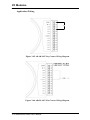
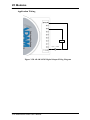
ADAM-4017+ 8-channel Differential Analog Input Module
Chapter 3 I/O Modules 3-29
Vin0-
Vin1-
Vin0+
Vin2-
Vin1+
Vin3-
Vin2+
Vin4-
Vin3+
Vin4+
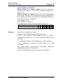
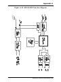
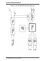
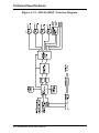
I/O Modules
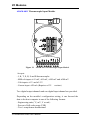
ADAM-4017+
DATA
ACQUISITION
MODULE
INPUT:
STRAIN GAUGE
mV, V, mA
CODE
INPUT R ANGE
08
±10 V
09
±5 V
0A
±1 V
0B
±500 mV
0C
±100 mV
0D
±20 mA
07
4 ~20 mA
(B)GND
(R)Vs+
(G)Data-
(Y)Data+
Vin7-
Vin7+
Vin6-
Vin6+
Vin5-
Vin5+
OUPUT:
RS-485
Figure 3-26 ADAM-4017+ 8-ch. differential analog input module
Jumper setting (ADAM-4017+)
1. JP0~JP7
JP0~
JP7
20 mA Input Range
Voltage Input range
Mapping to
Channel
Ch.
1
Ch.
2
Ch.
3
Ch.
4
Ch.5
Ch.6
Ch.7
Ch.8
JP 0
JP 2
JP 4
JP 6
JP 1
JP 3
JP 5
JP 7
2. JP12 can Enable/Disable Watchdog Timer Function. The default
setting is closed, i.e., Watchdog Timer Function Enabled. Please
always keep JP12 closed and enable/disable the watchdog timer
function in ADAM-utility.
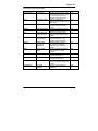
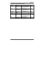
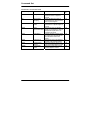
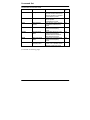
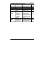
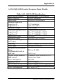
Technical specification of ADAM-4017+
3-30 ADAM 4000 Series User’s Manual
Chapter 3
Channel
Input Type
Input Range
Isolation Voltage
Fault and Over-voltage
protection
Sampling Rate
Input Impedance
Accuracy
Power Consumption
I/O Connector Type
8
mV, V, mA
±150 mV, ±500 mV, ±1 V, ±5 V, ±10 V,
±20 mA, 4 ~ 20 mA
Current Input doesn’t need an external
resistor
3000 VDC
With stands over-voltage up to ±35 V
10 sample/sec (total)
Voltage: 20 MΩ, Current: 120Ω
±0.1% or better
1.2 W @ 24VDC
10 pin plug-in terminal
Table 3-3 Technical specification of ADAM-4017+
ADAM-4018 8-channel Analog Input Module
Chapter 3 I/O Modules 3-31
Vin 0-
Vin 0+
Vin 1-
Vin 1+
Vin 2-
Vin 2+
Vin 3-
Vin 3+
Vin 4-
Vin 4+
I/O Modules
ADAM-4018
?00 mV
03
?00 mV
04
?V
05
?.5 V
06
?0 mA
DE
DF
T/C J
T/C K
10
11
T/C T
T/C E
12
13
T/C R
T/C S
14
T/C B
(B) GND
?0 mV
02
(Y) DATA+
Vin 7+
AGND
Vin 6+
Vin 5-
Vin 5+
OUPUT:
RS-485
?5 mV
01
INIT*
INPUT:
mV, V, mA
Thermocouple
INPUT RANGE
00
(R) +Vs
CODE
(G) DATA-
DATA
ACQUISITION
MODULE
Figure 3-27 ADAM-4018 8-channel Thermocouple Input Module
Channels:
- Six differential, two single-ended
Accepts:
- J, K, T, E, R, S and B thermocouples
- Millivolt inputs: ±15 mV, ±50 mV, ±100 mV and ±500 mV
- Volt inputs: ±1 V and ±2.5 V
- Current input: ±20 mA (requires a 125 resistor)
The module forwards the data to the host computer in engineering units
(oC, mV, V or mA)
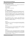
ADAM-4018M 8-channel Analog Input Data logger
3-32 ADAM 4000 Series User’s Manual
Vin 0-
Vin 0+
Vin 1-
Vin 1+
Vin 2-
Vin 2+
Vin 3-
Vin 3+
Vin 4-
Vin 4+
Chapter 3
ADAM-4018M
CODE
?00 mV
04
?V
05
?.5 V
06
?0 mA
DE
DF
T/C J
T/C K
10
11
T/C T
T/C E
12
13
T/C R
T/C S
14
T/C B
(B) GND
?00 mV
03
(R) +Vs
?0 mV
02
(Y) DATA+
Vin 7+
AGND
Vin 6+
Vin 5-
OUPUT:
RS-485
?5 mV
01
INIT*
INPUT:
mV, V, mA
Thermocouple
Vin 5+
INPUT RANGE
00
(G) DATA-
DATA
ACQUISITION
MODULE
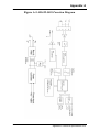
Figure 3-28 ADAM-4018M 8-channel Analog Input Data Logger
Channels:
- Six differential, two single-ended
Accepts:
- J, K, T, E, R, S and B thermocouples
- Millivolt inputs: ±15 mV, ±50 mV, ±100 mV, ±500 mV
- Volt inputs: ±1 V and ±2.5 V
- Current input: ±20 mA (requires a 125 resistor)
The module forwards the data to the host computer in engineering units
(oC, mV, V, or mA)
Storage Capacity:
- 128 KB flash memory
ADAM-4018+ 8-channel Thermocouple Input Module
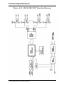
Chapter 3 I/O Modules 3-33
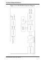
I/O Modules
Figure 3-29 ADAM-4018+ 8-ch. thermocouple input module
JP0~
JP7
4~20 mA Input Range
Voltage Input range
Mapping to
Channel
Ch.
1
Ch.
2
Ch.
3
Ch.
4
Ch.5
Ch.6
Ch.7
Ch.8
JP 0
JP 2
JP 4
JP 6
JP 1
JP 3
JP 5
JP 7
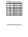
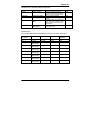
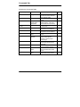
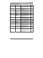
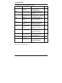
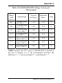
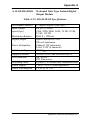
Technical specification of ADAM-4018+
Channel
Input Type
Input range and T/C type
8
Thermocouple
±20 mA, 4~20 mA
J 0 ~ 760° C
K 0 ~ 1370° C
T -100 ~ 400° C
E 0 ~ 1000° C
R 500 ~ 1750° C
S 500 ~ 1750° C
B 500 ~ 1800° C
Isolation Voltage
Fault and over-voltage protection
3000 VDC
Withstands over voltage up to ±35 V
3-34 ADAM 4000 Series User’s Manual
Chapter 3
Sampling Rate
Input Impedance
Accuracy
Power Consumption
I/O Connector Type
10 sample/sec (total)
Voltage: 20 MΩ, Current: 120Ω
±0.1% or better
0.8 W @ 24VDC
10 pin plug-in terminal
Table 3-4 Technical specification of ADAM-4018+
Application Wiring
Figure 3-30 Current Input Wiring Diagram of ADAM-4017
Vin0-
11
Vin0+
V
mV/V
+
Figure 3-31(a) ADAM-4017 Differential Input Wiring Diagram (Ch0 ~ Ch5)
Chapter 3 I/O Modules 3-35
I/O Modules
1
Vin5+
Vin5-
+
Vin6+
mV/V
AGND
-
Vin7+
Figure 3-31(b) ADAM-4017 Single-ended Input Wiring Diagram (Ch6 and Ch7)
Vin 1Vin 1+
-
Vin 0-
V
11
Vin 0+
mV/V
+
Vin 1Vin 1+
-
Vin 011
± 4~20 mA
Vin 0+
+
Built-in 125 Ohm Resister
Figure 3-32 ADAM-4017+ Voltage and Current Input Wiring Diagram
3-36 ADAM 4000 Series User’s Manual
Chapter 3
Vin 1Vin 1+
Vin 011
Vin 0+
-
T/C or 4~20mA
+
Figure 3-33 ADAM-4018+ Thermocouple Input Wiring Diagram
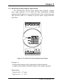
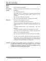
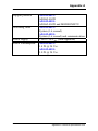
3.8 ADAM-4019+ 8-channel Universal Analog Input Module
The ADAM-4019+ is universal analog input module to integrate
with various AI modules into one. It not only reduces the hardware cost,
but also simplifies the wiring complexity. Furthermore, the ADAM4019+ provides the burnt-out detection functionality for 4~20mA and
all thermocouple input.
Chapter 3 I/O Modules 3-37
I/O Modules
Figure 3-34 ADAM-4019+ 8-channel Universal Analog Input
The jumper setting of ADAM-4019+ for input type selection:
JP0~JP7
20mA Input Range
Voltage Input range
Mapping to Channel
Ch.0 Ch.1 Ch.2 Ch.3 Ch.4 Ch.5 Ch.6 Ch.7
JP 0 JP 1 JP 2 JP 3 JP 4 JP 5 JP 6 JP 7
*It is built the 120Ω resister inside under current input mode
3-38 ADAM 4000 Series User’s Manual
Chapter 3
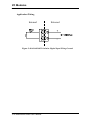
Application Wiring
120
Figure 3-35 ADAM-4019+ Universal Analog Input Wiring Diagram
Chapter 3 I/O Modules 3-39
I/O Modules
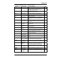
Technical specification of ADAM-4019+
Channel
Resolution
Input Type
Input type and temperature range
Isolation Voltage
Sampling Rate
Input Impedance
Accuracy
Power Consumption
I/O Connector Type
Burn-out Detection
8
16 bits
V, mV, mA, T/C
V: ±1 V , ±2.5 V, ±5 V , ±10 V
mV: ±100 mV , ±500 mV
mA: ±20 mA (with 120 Ω resister)
4~20mA (with 120 Ω resister)
Thermocouple:
J
0 to 760 °C
K
0 to 1370 °C
T -100 to 400 °C
E
0 to 1000 °C
R 500 to 1750 °C
S 500 to 1750 °C
B 500 to 1800 °C
3000 VDC
10 samples/sec (total)
Voltage: 20 MΩ, Current: 120Ω
±0.1% or better
1.0W @ 24VDC
10 pin plug-in terminal
4~20mA and all thermocouple input
Table 3-5 Technical specification of ADAM-4019+
3-40 ADAM 4000 Series User’s Manual
Chapter 3
3.9 ADAM-4021 Analog Output Module
Analog output module receives its digital input through an RS-485
interface from the host computer. The format of the data is either two’s
complement hexadecimal format or percentage of full-scale range
(FSR), depending on the module’s configuration. It then uses its
microprocessor-controlled D/A converter to convert the digital data into
output signals.
You will get a true read-back of the analog output signal from the
unit’s ADC, which monitors the output independently. You can also
specify slew rates and start up currents through the configuration
software. The Analog Output Module can supply single-channel analog
output in a range of voltages or currents.
Furthermore, it will protect your equipment from power surges at
the ground terminal by providing opto-isolation of the D/A output and
up to 3000 VDC transformer based isolation.
Slew Rate
The slew rate is defined as the discrepancy between the present
number of milliamps (or Volts) per second and the required output
currents (or voltages). An ADAM analog output module may be
configured for a specific slew rate.
Chapter 3 I/O Modules 3-41
I/O Modules
ADAM-4021 Analog Output Module
Figure 3-36 ADAM -4021 Analog Output Module
Depending on its configuration settings the module accepts the
following formats from the host computer:
- Engineering units
- Percent of full-scale range (FSR)
- Two’s complement hexadecimal format,
Output types:
- Voltage: 0 ~ 10 V
(Slew rate: 0.0625 to 64 V/sec)
- Currents: 0 ~ 20 mA, or 4 ~ 20 mA.
(Slew rate: 0.125 to 128 mA/sec)
3-42 ADAM 4000 Series User’s Manual
Chapter 3
Application Wiring
Figure 3-37 ADAM-4021 Analog Output Wiring Diagram
Chapter 3 I/O Modules 3-43
I/O Modules
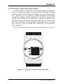
3.10 ADAM-4024 4-channel Analog Output Module
ADAM-4024 is a 4-channel analog output module with mixed type
I/O. Under some circumstances, it is, however, a demand for multiple
analog outputs to fulfill particular applications without many duplicate
modules. ADAM-4024 is designed to achieve this purpose by
integrating four A/O channels and four isolated D/I channels into only
one module. The four digital input channels function as an interlock for
emergency latch output.
ADAM-4024 inherited from ADAM-4021, but provide multi-range
AO support, allows its four A/O channels working at the same time with
different and more output ranges. For example, it can have 4~20 mA and
±10 V at its output. To ensure the operation of machines and facilities,
ADAM-4024 has the functionality of slew rate control. Output slope is
programmable through ramping/clamping the slew rate. Unlike
traditional mechanism, ADAM-4024 permits users to substitute its
default value at the start up. Users can easily set up and configure the
module to be more adaptive.
Figure 3-38 ADAM-4024 4-channel Analog Output Module
3-44 ADAM 4000 Series User’s Manual
Chapter 3
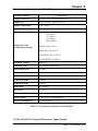
Technical specification of ADAM-4024
• Resolution: 12-bit
• Output Type: mA, V
• Output Range: 0~20 mA, 4~20 mA, and ±10V
• Isolation Voltage: 3000 VDC
• Output Impedance: 0.5 Ω
• Accuracy:
±0.1% of FSR for current output
±0.2% of FSR for voltage output
• Zero Drift:
Voltage output: ±30 µV/°C
Current output: ±0.2 µA/°C
• Span Temperature Coefficient: ±25 ppm/°C
• Output Slope Rate:
0.125 ~ 128 mA/sec.
0.0625 ~ 64 V/sec.
• Current Load Resistor: 0 to 500
• Built-in Watchdog Timer
• Isolation Digital Input
Channel: 4
Level 0: +1V max
Level 1: +10~30 VDC
Chapter 3 I/O Modules 3-45
I/O Modules
Application Wiring
Figure 3-39 ADAM-4024 Pin Define and Wiring Diagram
3-46 ADAM 4000 Series User’s Manual
Chapter 3
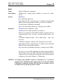
3.11 ADAM-4050 Digital I/O Module
The ADAM-4050 features seven digital input and eight digital
output channels. The outputs are open-collector transistor switches that
you can control from the host computer. You can also use the switches
to control solid-state relays, which can be applied to equipments such as
heaters and pumps. The host computer can use the module's digital
inputs to determine the states of limit, safety switches, and remote
digital signals.
Figure 3-40 ADAM-4050 Digital I/O Module
Channels:
- 7 input channels
- 8 output channels
Digital Input:
- Logic level 0: +1 V max.
- Logic level 1: +3.5 ~ 30 V
Digital Output:
- Open collector to 30 V, 30 mA max. load
Chapter 3 I/O Modules 3-47
I/O Modules
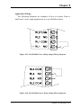
Application Wiring
Figure 3-41 ADAM-4050 TTL Input Wiring Diagram
Figure 3-42 ADAM-4050 Contact Closure Input Wiring Diagram
Figure 3-43 ADAM-4050 Digital Output Wiring Diagram Used with SSR
3-48 ADAM 4000 Series User’s Manual
Chapter 3
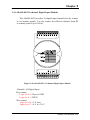
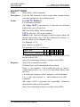
3.12 ADAM-4051 16-channel Isolated Digital Input Module
The ADAM-4051 is a 16 channel Digital Input Module. It is built
with 2500VDC optical isolation, and it is suitable for critical applications.
The main difference from other modules is that ADAM-4051 accepts
10 ~ 50V input voltage to fit various digital signals like 12 V, 24 V, and
48 V. Moreover, users can read the current status from the LED
indicators on the front panel.
Figure 3-44 ADAM-4051 16-channel Isolated Digital Input Module
•
•
•
•
•
•
•
Channel: 16
Optical Isolation: 2500 VDC
Opto-isolator response time: 25 μs
Over-voltage Protect: 70 VDC
ESD (Electro Static Discharge): 2000 VDC
LED Indicator: On: Active; Off: Non-active
Input Voltage:
Dry Contact Logic level 1: close to GND, Logic level 0: open
Wet Contact Logic level 1: 10 ~ 50 V, Logic level 0: 3 V
• Power consumption: 1W @ 24 VDC
• I/O Connector Type: 13 pin plug-in terminal*2
Chapter 3 I/O Modules 3-49
I/O Modules
Application Wiring
Figure 3-45 ADAM-4051 Dry Contact Wiring Diagram
Figure 3-46 ADAM-4051 Wet Contact Wiring Diagram
3-50 ADAM 4000 Series User’s Manual
Chapter 3
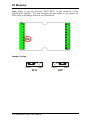
3.13 ADAM-4052 Isolated Digital Input Module
The ADAM-4052 provides eight digital input channels. Among
these eight channels, six of them are fully independent isolated
channels and the other two are isolated channels with a common ground.
They all have 5000 VRMS isolation to prevent power surges from the
input lines
Figure 3-47 ADAM-4052 Isolated Digital Input Module
Channels: 8
- 6 differential channels (fully independent isolated channels)
- 2 single-ended channels (isolated channels with common ground)
Digital Input:
- Logic level 0: +1 V max.
- Logic level 1: +3 ~ 30 V
Chapter 3 I/O Modules 3-51
I/O Modules
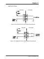
Application Wiring
Internal
External
Figure 3-48 ADAM-4052 Isolation Digital Input Wiring Ground
3-52 ADAM 4000 Series User’s Manual
Chapter 3
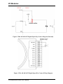
3.14 ADAM-4053 16-channel Digital Input Module
The ADAM-4053 provides 16 digital input channels for dry contact
or wet contact signals. For dry contact, the effective distance from DI
to contact point is up to 500 m.
Figure 3-49 ADAM-4053 16-channel Digital Input Module
Channels: 16 Digital Input
-Dry contact
Logic level 0: Close to GND
Logic level 1: OPEN
-Wet contact
Logic level 0: +2 V max.
Logic level 1: +4 V to +30 V
Chapter 3 I/O Modules 3-53
I/O Modules
Note: There is one pin showing “INIT*/DI15” on the connector of the
ADAM-4053 module. You can configure the pin define by the jumper on
PCB (refer to the image below to see its location):
Jumper Setting:
DI15
INIT*
DI15
3-54 ADAM 4000 Series User’s Manual
DI15
INIT*
INIT*
Chapter 3
Application Wiring
Internal
External
Figure 3-50 ADAM-4053 Wet Contact Input Wiring Diagram
Internal
External
Figure 3-51 ADAM-4053 Contact Closure Input Wiring Diagram
Chapter 3 I/O Modules 3-55
I/O Modules
3.15 ADAM-4055 16-channel Isolated Digital I/O Module
The ADAM-4055 offers 8 channel isolated digital input and 8
channel isolated digital output for critical applications. The inputs
accept 10~50 V voltage, and the outputs can supply 5~40 VDC at the
open collector. The ADAM-4055 is user friendly with built LED
indicator for status reading.
Notice: we had updated the digital input dry/wet contact option by
using jumper selection. The default setting is to support these two DI
contacts both at the same time. However, a customer can also choose
his or her needs by supporting only one. Please refer to the following
wiring illustration figure 3-54b for more details
Figure 3-52 ADAM-4055 16-channel Digital I/O Module
3-56 ADAM 4000 Series User’s Manual
Chapter 3
Application Wiring:
Figure 3-53 ADAM-4055 Digital Output Wiring Diagram
Figure 3-54a ADAM-4055 Digital Input Dry Contact Wiring Diagram
Chapter 3 I/O Modules 3-57
I/O Modules
Figure 3-54b ADAM-4055 Digital Input Dry Contact Diagram (Internal)
Figure 3-55a ADAM-4055 Digital Input Wet Contact Wiring Diagram
3-58 ADAM 4000 Series User’s Manual
Chapter 3
Figure 3-55b ADAM-4055 Digital Input Wet Contact Diagram (Internal)
Figure 3-56a ADAM-4055 Default Jumper Setting for the Digital Input Wiring
(Support dry and wet contact digital input at the same time)
Chapter 3 I/O Modules 3-59
I/O Modules
Figure 3-56b ADAM-4055 Default Jumper Setting for the Digital Input Wiring
3-60 ADAM 4000 Series User’s Manual
Chapter 3
3.16 ADAM-4056S 12-channel Sink Type Isolated Digital Output
Module
ADAM-4056S is a 12-channel sink type isolated digital output
module. The isolated channels are designed for digital output for
critical applications. Open collector outputs can provide from +5 to
+40 VDC, and both ADAM ASCII and Modbus/RTU protocols are
supported. LED indicators are used for status reading.
Figure 3-57 ADAM-4056S 12-channel Sink Type Isolated Digital Output Module
Technical Specification of ADAM-4056S
Number of Output Channel: 12
Digital Output:
Open Collector from +5 ~ +40V, 200mA max. load (Sink)
LED Indicator: On: Active, Off: Non-active
Power Consumption: 1 W @ 24VDC
Optical isolation: 5000 VDC
Supports Modbus/RTU protocol
I/O Connector Type: 10 pin plug-in terminal*2
Support Safety Value:
Force the DO channels to safety status when communication is in
time-out and over pre-defined period.
Chapter 3 I/O Modules 3-61
I/O Modules
Application Wiring
-
LOAD
+
+5V ~ +40V
Figure 3-58 ADAM-4056S Digital Output Wiring Diagram
3-62 ADAM 4000 Series User’s Manual
Chapter 3
3.17 ADAM-4056SO 12-channel Source Type Isolated Digital Output
Module
ADAM-4056SO is a 12-channel source type isolated digital output
module. The 12 isolated digital output channels are designed for
critical applications. The digital output signals are sent in the range of
10 ~ 35 VDC with maximum 1A per channel, and both ADAM ASCII
and Modbus/RTU protocols are supported. The LED indicators
provide status reading of the module.
Figure 3-59 ADAM-4056SO 12-channel Source Type Isolated
Digital Output Module
Technical Specification of ADAM-4056SO
Number of Output Channel: 12
Digital Output: VCC: +10 ~ 35VDC, 1A per Channel ( Source)
LED Indicator: On: Active, Off: Non-active
Power Consumption: 1 W @ 24VDC
Optical isolation: 5000 VDC
Supports Modbus/RTU protocol
I/O Connector Type: 10 pin plug-in terminal*2
Leakage current : 50μA
Support Safety Value:
Force the DO channels to safety status when communication is in
time-out and over pre-defined period.
Chapter 3 I/O Modules 3-63
I/O Modules
Application Wiring
Figure 3-60 ADAM-4056SO Digital Output Wiring Diagram
3-64 ADAM 4000 Series User’s Manual
Chapter 3
3.18 ADAM-4060/4068 Relay Output Module
The ADAM Relay Output Module is a low-cost alternative to SSR
modules. The ADAM-4060 Relay Output Module provides four relay
channels; two of them are Form A, and two are Form C. The ADAM4068 Relay Output Module provides eight channels. Four of the
channels are Form A, and four are Form C. These two modules are
excellent for ON/OFF control or low-power switching applications and
they are able to support the safety value setting.
ADAM-4060 4-channel Relay Output Module
Figure 3-61 ADAM-4060 4-channel Relay Output Module
Contact rating for Form A and Form C: (Resistive)
AC
0.6 A @ 125 V
0.3 A @ 250 V
DC
2 A @ 30 V
0.6 A @ 110 V
Chapter 3 I/O Modules 3-65
I/O Modules
RL0 NC
RL0 NO
RL0 COM
RL1 NO
RL1 NC
RL1 COM
RL2 NO
RL2 NC
RL2 COM
RL3 NO
RL3 COM
RL4 NO
RL4 COM
ADAM-4068 8-channel Relay Output Module
SIGNAL
TYPE
RRELA
E L A YY3,4,5,6
0,1,2,3
F o rm A
FORMA
RRELA
E L A YY0,1,2,7
4,5,6,7
F o rm C
FORM C
0 1 2 3 4 5 6 7
(R) +Vs
(B) GND 10
(Y) DATA+
(G) DATA-
INIT*
RL7 NC
NC
RL7 NO
RL7 COM
RL6 NO
RL6 COM
RL5 NO
RL5 COM
RELAY
Figure 3-62 ADAM-4068 8-channel Relay Output Module
Contact Rating for Form A and Form C: (Resistive)
AC
125 V @ 0.6 A
250 V @ 0.3 A
DC
30 V @ 2 A
110 V @ 0.6 A
NOTICE: This electric current is under the load of resistance. If
you try to use the load of inductance, the electric current would be
less the above-mentioned value.
3-66 ADAM 4000 Series User’s Manual
Chapter 3
Application Wiring
The following diagrams are examples of how to connect Form A
and Form C relay output applications to your ADAM modules.
Figure 3-63 ADAM-4060 Form A Relay Output Wiring Diagram
Figure 3-64 ADAM-4060 Form C Relay Output Wiring Diagram
Chapter 3 I/O Modules 3-67
I/O Modules
Figure 3-65 ADAM-4068 Form C Relay Output Wiring Diagram
RL4 NO
RL4 COM
RL3 NO
RL3 COM
Figure 3-66 ADAM-4068 Form A relay output Wiring Diagram
3-68 ADAM 4000 Series User’s Manual
Chapter 3
3.19 ADAM-4069 8-channel Relay Output Module
The ADAM-4069 Relay Output Module provides eight channels; four
are Form A and the rest are Form C. This module is excellent for ON/OFF
control or low-power switching applications.
Figure 3-67 ADAM-4069 Relay Output Module
Chapter 3 I/O Modules 3-69
I/O Modules
Specification:
z
z
z
z
z
z
Number of Relay Output Channel: 8
Digital Output: (Source)
4 Form A , 4 Form C
AC 5A@240V
DC 5A@30V
ON/OFF : 5ms/ 5.6ms
Power Consumption: 2.2 W
Supports Modbus/RTU protocol
I/O Connector Type: 13-pin plug-terminal * 2
Support Safety Value: Force the DO channels to safety status
when communication is in time-out and over pre-defined period.
Wiring:
Figure 3-68 ADAM-4069 Form C Relay Output
3-70 ADAM 4000 Series User’s Manual
Chapter 3
Figure 3-69 ADAM-4069 Form A Relay Output
Chapter 3 I/O Modules 3-71
I/O Modules
3.20 ADAM-4080/4080D Counter/Frequency Input Modules
ADAM-4080/4080D Counter/frequency input module has two 32bit counter input channels (counter 0 and counter 1) with built-in
programmable timer for frequency measurement. These cost-effective
modules let you monitor counter/frequency data as measurements are
taken.
Front Panel LED Indicator (ADAM-4080D only)
The 5-digit LED display of the ADAM-4080D lets you monitor its
counter data right at the source. The module's LED display shows
counter values as well as high-low alarm messages when the counter
exceeds its programmed limits (direct display).
Another option is to display the data sent by the host computer. The
module first sends counter data to the host computer for conversion or
calculation. The host computer then sends the data back to the ADAM4080D and displays on the module's LED display (remote display).
Signal Input Mode
The ADAM-4080/4080D provides separate terminals for photo
isolated input and non-isolated input to simplify the wiring. Optoisolated input provides 2500 VRMS isolation to protect your equipment
from power surges at the ground terminal. After you make the physical
connections, program the module to identify which of its two input
terminals should be activated (isolated or non-isolated terminals).
Programmable Digital Filter
The ADAM-4080/4080D module includes a unique programmable
digital filter to reject noise from the input lines. You can specify
separate time constant like minimum signal width at high level and
minimum signal width at low level. This provides stable output
readings.
Programmable Threshold
When the ADAM-4080/4080D is programmed for non-isolated
input, you can set a high and low trigger level. Like the programmable
digital filter, the programmable threshold rejects noise from the input
lines and provides a stable input readings
3-72 ADAM 4000 Series User’s Manual
Chapter 3
External Control (Gate mode)
Aside from the GND and counter terminal, each channel has a gate
terminal to connect to an external gate signal. The gate signal (high or
low) can trigger the counter from start or stop counting. The gate mode
can be among these three options, low, high or disabled (low means that
counting starts when the gate signal is low. It stops once the gate signal
becomes high)
Programmable Alarm Output
The ADAM-4080 module provides a configurable alarm for each
counter. The ADAM-4080D provides high and low alarm functions for
counter 0. When the counter reaches an alarm limit, it will trigger the
built-in digital output of machine ON/OFF control. The alarm limits
may be downloaded into the module's EEPROM by the host computer.
The initial count value of ADAM-4080 module's counter can be
configured in any values.
The alarm functions can be enabled or disabled remotely. When the
alarm functions are enabled, digital output channels are used to indicate
the alarm states. For ADAM-4080, digital output channel 0 equals to
the alarm state of counter 0, and digital output channel 1 equals to the
alarm state of counter 1. For ADAM-4080D, digital output channel 0
equals to the low alarm state of counter 0, and digital output channel 1
equals to the high alarm state of counter 0.
Every A/D conversion will be followed by a comparison of alarm
limits. If the input value exceeds one of these limits, the corresponding
alarm state is set to ON.
There are two alarm mode options, momentary and latching, for
ADAM-4080D. If the alarm is in latching mode, the alarm will stay on
even when the input value returns within the limits. An alarm in
latching mode can be turned off by issuing a Clear Alarm command
from the host computer. A latching alarm is cleared by the module
when the opposite alarm is set. For example, the alarm is in latching
mode and the high alarm is then turned ON. When the module receives
a value that is lower than the low alarm limit, it will clear the high
alarm and turn the low alarm ON.
When the alarm is in Momentary mode, the alarm will be turned
OFF as soon as the input value returns within the limits.
The arrangement of coupling high and low alarm states with digital
output lines may be utilized to build ON/OFF controllers that can
operate without the host computer involvement.
Chapter 3 I/O Modules 3-73
I/O Modules
GATE 1-
IN 1-
GATE 1+
IN 1+
GATE 0-
IN 0-
GATE 0+
DO 0
IN 0+
DO 1
ADAM-4080 Counter/Frequency Input Modules
ADAM-4080
DATA
ACQUISITION
MODULE
CODE
INPUT RANGE
50
COUNTER
51
FREQUENCY
(B) GND
(R) +Vs
(G) DATA-
(Y) DATA+
INIT*
GATE 1
IN 1
D.GND
GATE 0
IN 0
(Non-isolation)
Figure 3-70 ADAM-4080 Counter/Frequency Input Module
Channels: 2 independent 32-bit counters (counter 0 and counter 1)
Input frequency: 50 kHz max.
Input mode: Isolated or non-isolated
Isolation input level:
- Logic level 0: +1 V max
- Logic level 1: +3.5 V to +30 V
- Input Impedance: 1.2 kΩ
Non-isolation input level (programmable threshold):
- Logic level 0: 0 to +5V (default = 0.8 V)
- Logic level 1: 0 to +5V (default = 2.4 V)
- Input Impedance: 50 MΩ
3-74 ADAM 4000 Series User’s Manual
Chapter 3
GATE 1-
IN 1-
GATE 1+
IN 1+
GATE 0-
IN 0-
GATE 0+
IN 0+
DO 1/HI
DO 0/LO
ADAM-4080D Counter/Frequency Input Modules with LED Display
(Photo-isolation)
ADAM-4080D
DATA
ACQUISITION
MODULE
CODE
INPUT RANGE
50
COUNTER
51
FREQUENCY
(B) GND
(R) +Vs
(G) DATA-
(Y) DATA+
INIT*
GATE 1
IN 1
D.GND
GATE 0
IN 0
(Non-isolation)
Figure 3-71 ADAM-4080D Counter/Frequency Input Module
with LED Display
Channels: 2 independent 32-bit counters (counter 0 and counter 1)
Input frequency: 50 kHz max.
Input mode: Isolated or non-isolated
Isolation input level:
- Logic level 0: +1 V max
- Logic level 1: +3.5 V to +30 V
- Input Impedance: 1.2 kΩ
Non-isolation input level (programmable threshold):
- Logic level 0: 0 to +5V (default = 0.8 V)
- Logic level 1: 0 to +5V (default = 2.4 V)
- Input Impedance: 50 MΩ
Chapter 3 I/O Modules 3-75
I/O Modules
Application Wiring
Counter Input
IN0
Gate Control
GATE0
GND
D.GND
1
Figure 3-72 ADAM-4080/4080D Non-isolated Input
IN1+
IN1GATE1+
11
GATE1-
+
Counter Input
+
GATE Control
-
Figure 3-73 ADAM-4080/4080D Photo-isolated Input
3-76 ADAM 4000 Series User’s Manual
Command Set
4
Command Set
4.1 Introduction
In order to avoid communication conflicts among devices trying to send
data simultaneously, all the traffics are coordinated by the host
computer. This action is initiated by the host computer using a
command/response protocol.
When the modules are not transmitting, they are in listening mode. The
host issues a command to a module with a specified address and waits
for the module’s response. If there is no response, a timeout aborts the
sequence and returns the control to the host.
Changing ADAM’s configuration might require the module to perform
auto calibration before changes may take effect. This is the case when
the range is modified especially. The module has to perform all stages
of auto calibration which is also performed during the start up. When
the calibration process is underway, the module does not respond to any
other commands. The command set in the following pages includes the
exact delays that might occur as modules are reconfigured.
4.2 Syntax
[delimiter character][address][command][data][checksum] [carriage
return]
Every command begins with a delimiter character. There are four valid
characters: a dollar sign $, a pound sign #, a percentage sign % and an
at sign @.
The delimiter character is followed by a two-character address
(hexadecimal) that specifies the target module. The actual
two-character command follows by the address. Depending on the
command, an optional data segment may follows by a command string.
Furthermore, an optional two-character checksum may be appended to
the total string. Every command is terminated by a carriage return (cr).
ALL COMMANDS SHOULD BE ISSUED IN UPPERCASE
CHARACTERS!
4-2 ADAM 4000 Series User’s Manual
Chapter
4
Before the command set is given, we provide an I/O module commands
search table to help you find the commands that you wish to use. The
command set is divided into the following three categories:
• Analog Input Module commands
• Analog Output Module commands
• Digital I/O, Relay Output and Counter/Frequency Module
commands
Each Category starts with a command summary of a particular type of
module. However, they are explained in more depth at Chapter 5, 6 & 7
with detailed datasheets of each individual commands.
Although commands in different subsections sometimes share the same
format, the effect they have on a certain module can be completely
different from others. For example, the configuration command
%AANNTTCCFF affects analog input modules and analog output
modules differently. The full command set for every module is listed
below.
Chapter 4 Command Set 4-3
Command Set
4.3 I/O Module Commands Search Table
ADAM-4011 Command Table
Command Syntax
%AANNTTCCFF
Command Name
Configuration
$AA2
Configuration Status
$AAF
Read Firmware
Version
$AAM
Read Module Name
#AA
Analog Data In
$AA0
Span Calibration
$AA1
Offset Calibration
#**
Synchronized
Sampling
$AA4
Read Synchronized
Data
$AA3
CJC Status
$AA9SNNNN
CJC Offset
Calibration
(Continued on following page)
4-4 ADAM 4000 Series User’s Manual
Command Description
Sets the address, input range,baud
rate, data format, checksum
status, and/or integration time for a
specified analog input module
Returns the configuration
parameters for the specified
analog input module
Return the firmware version code
from the specified analog input
module
Return the module name from the
specified analog input module
Returns the input value from a
specified analog input module in
the currently configured data
format
Calibrates an analog input module
to correct for gain errors
Calibrates an analog input module
to correct for offset errors
Orders all analog input modules to
sample their input values and store
them in special registers
Returns the value that was stored
in the specified module's register
after the #** command
Returns the value of the CJC
sensor for a specified analog input
module
Calibrates the CJC sensor for
offset errors
Page No.
5-4
5-10
5-12
5-13
5-14
5-19
5-20
5-21
5-22
5-25
5-26
Chapter
4
ADAM-4011 Command Table (Continued)
Command Syntax
@AADI
Command Name
Read Digital I/O and
Alarm Status
@AADO(data)
Set Digital Output
@AAEAT
Enable Alarm
@AAHI(data)
Set High Alarm
@AALO(data)
Set Low Alarm
@AADA
@AACA
@AARH
Disable Alarm
Clear Latch Alarm
Read High Alarm
@AARL
Read Low Alarm
@AARE
Read Event Counter
@AACE
Clear Event Counter
Command Description
The addressed module returns the
state of its digital input channel, its
two digital output channels and the
status of its alarm
Set the values of the module's two
digital outputs (ON or OFF)
Enables the alarm in either
Momentary or Latching mode
Downloads the High alarm limit
value
Downloads the Low alarm limit
value
Disables all alarm functions
The latch alarm is reset
The addressed analog input
module is asked to return its high
alarm value
The addressed analog input
module is asked to return its low
alarm value
The addressed module is asked to
return its event counter value
The event counter is set to 0
Page No.
5-50
5-52
5-54
5-56
5-57
5-58
5-59
5-60
5-61
5-62
5-63
Chapter 4 Command Set 4-5
Command Set
ADAM-4011D Command Table
Command Syntax
%AANNTTCCFF
Command Name
Configuration
$AA2
Configuration Status
$AAF
Read Firmware
Version
$AAM
Read Module Name
#AA
Analog Data In
$AA0
Span Calibration
$AA1
Offset Calibration
#**
Synchronized
Sampling
$AA4
Read Synchronized
Data
$AAB
Open Thermocouple
Detection
$AA3
CJC Status
$AA9SNNNN
CJC Offset
Calibration
(Continued on following page)
4-6 ADAM 4000 Series User’s Manual
Command Description
Sets the address, input range,baud
rate, data format, checksum
status, and/or integration time for a
specified analog input module
Returns the configuration
parameters for the specified
analog input module
Return the firmware version code
from the specified analog input
module
Return the module name from the
specified analog input module
Returns the input value from a
specified analog input module in
the currently configured data
format
Calibrates an analog input module
to correct for gain errors
Calibrates an analog input module
to correct for offset errors
Orders all analog input modules to
sample their input values and store
them in special registers
Returns the value that was stored
in the specified module's register
after the #** command
Ask the module to respond
whether the thermocouple is open
or not
Returns the value of the CJC
sensor for a specified analog input
module
Calibrates the CJC sensor for
offset errors
Page No.
5-4
5-10
5-12
5-13
5-14
5-19
5-20
5-21
5-22
5-24
5-25
5-26
Chapter
4
ADAM-4011D Command Table (Continued)
Command Syntax
@AADI
Command Name
Read Digital I/O and
Alarm Status
@AADO(data)
Set Digital Output
@AAEAT
Enable Alarm
@AAHI(data)
Set High Alarm
@AALO(data)
Set Low Alarm
@AADA
@AACA
@AARH
Disable Alarm
Clear Latch Alarm
Read High Alarm
@AARL
Read Low Alarm
@AARE
Read Event Counter
@AACE
Clear Event Counter
Command Description
The addressed module returns the
state of its digital input channel, its
two digital output channels and the
status of its alarm
Set the values of the module's two
digital outputs (ON or OFF)
Enables the alarm in either
Momentary or Latching mode
Downloads the High alarm limit
value
Downloads the Low alarm limit
value
Disables all alarm functions
The latch alarm is reset
The addressed analog input
module is asked to return its high
alarm value
The addressed analog input
module is asked to return its low
alarm value
The addressed module is asked to
return its event counter value
The event counter is set to 0
Page No.
5-50
5-52
5-54
5-56
5-57
5-58
5-59
5-60
5-61
5-62
5-63
Chapter 4 Command Set 4-7
Command Set
ADAM-4012 Command Table
Command Syntax
%AANNTTCCFF
Command Name
Configuration
#AA
Analog Data In
$AA0
Span Calibration
$AA1
Offset Calibration
#**
Synchronized
Sampling
$AA4
Read Synchronized
Data
$AA2
Configuration Status
$AAF
Read Firmware
Version
$AAM
Read Module Name
(Continued on following page)
4-8 ADAM 4000 Series User’s Manual
Command Description
Sets the address, input range,baud
rate, data format, checksum
status, and/or integration time for a
specified analog input module
Returns the input value from a
specified analog input module in
the currently configured data
format
Calibrates an analog input module
to correct for gain errors
Calibrates an analog input module
to correct for offset errors
Orders all analog input modules to
sample their input values and store
them in special registers
Returns the value that was stored
in the specified module's register
after the #** command
Returns the configuration
parameters for the specified
analog input module
Return the firmware version code
from the specified analog input
module
Return the module name from the
specified analog input module
Page No.
5-4
5-14
5-19
5-20
5-21
5-22
5-10
5-12
5-13
Chapter
4
ADAM-4012 Command Table (Continued)
Command Syntax
@AADI
Command Name
Read Digital I/O and
Alarm Status
@AADO(data)
Set Digital Output
@AAEAT
Enable Alarm
@AAHI(data)
Set High Alarm
@AALO(data)
Set Low Alarm
@AADA
@AACA
@AARH
Disable Alarm
Clear Latch Alarm
Read High Alarm
@AARL
Read Low Alarm
@AARE
Read Event Counter
@AACE
Clear Event Counter
Command Description
The addressed module returns the
state of its digital input channel, its
two digital output channels and the
status of its alarm
Set the values of the module's two
digital outputs (ON or OFF)
Enables the alarm in either
Momentary or Latching mode
Downloads the High alarm limit
value
Downloads the Low alarm limit
value
Disables all alarm functions
The latch alarm is reset
The addressed analog input module
is asked to return its high alarm
value
The addressed analog input module
is asked to return its low alarm
value
The addressed module is asked to
return its event counter value
The event counter is set to 0
Page No.
5-50
5-52
5-54
5-56
5-57
5-58
5-59
5-60
5-61
5-62
5-63
Chapter 4 Command Set 4-9
Command Set
ADAM-4013 Command Table
Command Syntax
%AANNTTCCFF
Command Name
Configuration
#AA
Analog Data In
$AA0
Span Calibration
$AA1
Offset Calibration
#**
Synchronized
Sampling
$AA4
Read Synchronized
Data
$AA2
Configuration Status
$AAF
Read Firware
Version
$AAM
Read Module Name
4-10 ADAM 4000 Series User’s Manual
Command Description
Sets the address, baud rate, data
format, checksum status, and/or
integration time for a specified
analog input module
Returns the input value from a
specified analog input module in
the currently configured data
format
Calibrates an analog input moudle
to correct for gain errors
Calibrates an analog input moudle
to correct for offset errors
Orders all analog input modules to
sample their input values and store
them in special registers
Returns the value that was stored
in the specified module's register
after the #** command
Returns the configuration
parameters for the specified
analog input module
Returns the firmware version code
from the specified analog input
module
Returns the module name from the
specified analog input module
Page No.
5-4
5-14
5-19
5-20
5-21
5-22
5-10
5-12
5-13
Chapter
4
ADAM-4015/ADAM-4015T Command Table
Command
Syntax
%AANNTTCCFF
Command Name
Command Description
Configuration
$AA2
Configuration Status
Sets the address, baud rate, data format,
checksum status, and/or integration time for a
specified analog input module
Returns the configuration parameters for the
specified analog input module
$AAF
$AAM
Read Firmware
Version
Read Module Name
#AA
Analog Data In
#AAN
Read Analog Input
from Channel N
$AA5VV
Enable/Disable
Channels for
Multiplexing
Read Channel
Status
Synchronized
Sampling
$AA6
#**
Return the firmware version code from the
specified analog input module
Return the module name from the specified
analog input module
Returns the input value from a specified analog
input module in the currently configured data
format
Returns the input value from a specified channel
of analog input module in the currently configured
data format
Enable or disable the individual channels in an
analog module
Page
No.
5-4
5-10
5-12
5-13
5-14
5-16
5-17
Get the enable/disable status of all channels in
an analog module
Orders all analog input modules to sample their
input values and store them in special registers
5-18
5-21
$AA4
Read Synchronized
Data
Returns the value that was stored in the specified
module's register after the #** command
5-22
$AAB
Channel Diagnose
5-24
$AA0Ci
Single Channel
Span Calibration
Diagnose channel status in over range, under
range, and wire opening
Calibrates a specified channel to correct for gain
errors
$AA1Ci
Single Channel
Offset Calibration
Calibrates a specified channel to correct for offset
errors
5-28
$AA7CiRrr
Single Channel
Range Configuration
Configure the input type and range of the
specified channel in an analog input module
5-29
$AA8Ci
Read Single
Channel Range
Configuration
Watchdog Timer
Setting
Get the input type and range of the specified
channel in an analog input module
5-30
5-31
$AAXnnnn
5-27
$AAY
Read Watchdog
Timer Setting
Set communication WDT cycle time from 0000 ~
9999 (unit: 0.1 second. if value is 0000, the
communication WDT function will be disable)
Read the cycle time setting of communication
WDT
$AAS0
Internal Calibration
Internal self-calibration for offset and gain errors
5-33
$AAS1
Reload default
calibrating
parameter
Reload factory default calibrating parameter to
overwrite current calibrating parameter
5-34
5-32
Chapter 4 Command Set 4-11
Command Set
ADAM-4016 Command Table
Command Syntax
%AANNTTCCFF
Command Name
Configuration
$AA2
Configuration Status
$AAF
Read Firmware
Version
$AAM
Read Module Name
#AA
Read Analog Input
$AA0
Span Calibration
$AA1
Offset Calibration
#**
Synchronized
Sampling
$AA4
Read Synchronized
Data
$AA6
Get Excitation
Voltage Output Value
$AA7
Excitation Voltage
Output
Start-up Voltage
Output Configuration
$AAS
$AAE
Trim Calibration
$AAA
Zero Calibration
$AAB
Span Calibration
(Continued on following page)
4-12 ADAM 4000 Series User’s Manual
Command Description
Set the address, input range, baud
rate, data format, checksum status
and/or integration time for the
specified analog input module
Return the configuration
parameters for the specified
analog input module
Return the firmware version code
from the specified analog input
module
Return the module name from the
specified analog input module
Return the input value from the
specified analog input module in
the currently configured data
format
Calibrate an analog input module
to correct for gain errors
Calibrate an analog input module
to correct for offset errors
Orders all analog input modules to
sample their input values and store
them in special registers
Returns the value that was stored
in the specified module's register
after the #** command
Returns either last value sent to
specified module by $AA7
command, or start-up output
voltage
Direct output excitation voltage
data to a specified module
Stores a default value in a
specified module. The output value
will take effect upon atartup.
Trims specified module a number
of units up or down
Tells the module to store
paramenters for zero calibration
Tells the module to store
parameters for span calibration
Page No.
5-4
5-10
5-12
5-13
5-14
5-19
5-20
5-21
5-22
5-65
5-66
5-67
5-69
5-70
5-71
Chapter
4
ADAM-4016 Command Table (Continued)
Command Syntax
@AADI
Command Name
Read Digital I/O And
Alarm Status
@AADO(data)
@AAEAT
Set Digital Output
Values
Enable Alarm
@AAHI(data)
@AALO(data)
@AADA
@AACA
Set High Alarm Value
Set Low Alarm Value
Disable Alarm
Clear Latch Alarm
@AARH
Read High Alarm
Value
Read Low Alarm
Value
@AARL
Command Description
Ask the addressed module to return
the state of its four digital output
channels and the status of its alarm
Set the values of the module's four
digital outputs (ON or OFF)
Enable the alarm in either
monentary or latching mode
Download the high alarm limit value
Download the low alarm limit value
Disable all alarm functions
Reset the module's latch alarm to
zero
Ask the addressed module to return
its high alarm value
Ask the addressed module to return
its low alarm value
Page No.
5-50
5-52
5-54
5-56
5-57
5-58
5-59
5-60
5-61
Chapter 4 Command Set 4-13
Command Set
ADAM-4017 Command Table
Command Syntax
%AANNTTCCFF
Command Name
Configuration
$AA2
Offset Calibration
$AAF
Read Channel Status
$AAM
Read Version
#AA
from Channel N
#AAN
Read Analog Input
$AA5VV
Configuration Status
$AA6
Enable/disable
Channels for
Multiplexing
Read Analog Input
from all Channels
Span Calibration
$AA0
$AA1
4-14 ADAM 4000 Series User’s Manual
Command Description
Set the address, input range, baud
rate, data format, checksum status
and/or integration time for the
specified analog input module
Return the configuration
parameters for the specified
analog input module
Return the firmware version code
from the specified analog input
module
Return the module name from the
specified analog input module
Return the input values from all
channels of the specified analog
input module
Return the input value from
channels number N of the
specified analog input module
Enables/disables multiplexing
simultaneously for seperate
channels of the specified input
module
Ask the specified input module to
return the status of all eight
channels
Calibrate the analog input module
to correct for gain errors
Calibrate the analog input module
to correct for offset errors
Page No.
5-4
5-9
5-11
5-12
5-13
5-15
5-16
5-17
5-18
5-19
Chapter
4
ADAM-4017+ Command Table
Command
Syntax
%AANNTTCCFF
$AA2
$AAF
$AAM
#AA
#AAN
$AA5VV
Command Name
Command Description
Configuration
Set the address, input range, baud rate,
data format, checksum status and/or
integration time for the specified analog
input module
Return the configuration parameters for
the specified analog input module
Return the firmware version code from the
specified analog input module
Return the module name from the
specified analog input module
Return the input values from all channels
of the specified analog input module
Return the input value from channels
number N of the specified analog input
module
Enables/disables multiplexing
simultaneously for seperate channels of
the specified input module
Ask the specified input module to return
the status of all eight channels
Configuration
Status
Read Version
Read the Module
Name
Read Analog Input
from all Channels
Read Analog Input
from Channel N
$AA0Ci
Enable/disable
Channels for
Multiplexing
Read Channel
Status
Span Calibration
$AA1Ci
Offset Calibration
$AA7CiRrr
Input Range
Setting
Read Input Range
$AA6
$AA8Ci
$AAXnnnn
Watchdog Timer
Setting
$AAY
Read Watchdog
Timer Setting
Page
No.
5-4
5-10
5-12
5-13
5-14
5-16
5-17
5-18
Gain error calibrate of assignment channel,
User have to input the external standard source
for calibrating process
Offset error calibrate of assignment channel,
User have to input the external standard source
for calibrating process
5-27
Input range setting individually
5-29
Get the input range of the assignment
channel
Set communication WDT cycle time from
0000 ~ 9999 (unit: 0.1 second. if value is
0000, the communication WDT function
will be disable)
Read the cycle time setting of
communication WDT
5-30
5-28
5-31
5-32
Chapter 4 Command Set 4-15
Command Set
ADAM-4017+
Input range and external calibrating input source for each input type
Range
bcode(Hex)
07
08
09
0a
0b
0c
0d
Input Range
Max. Signal
Min Signal
+/-4~20 mA
+/-10 V
+/-5 V
+/-1 V
+/-500 mV
+/-150 mV
+/-20 mA
+20.000
+10.000
+5.0000
+1.0000
+500.00
+150.00
+20.000
-20.000
-10.000
-5.0000
-1.0000
-500.00
-150.00
-20.000
4-16 ADAM 4000 Series User’s Manual
Displayed
Resolution
1uA
1mV
100.00uV
100.00uV
10uV
10uV
1uA
Chapter
4
ADAM-4018 Command Table
Command Syntax
%AANNTTCCFF
Command Name
Configuration
$AA2
Configuration Status
$AAF
Read Version
$AAM
Read Module Name
#AA
Read Analog Input
from all Channels
#AAN
Read Analog Input
from Channel N
$AA5VV
Enable/disable
Channels for
Multiplexing
$AA6
Read Channel
Status
$AA0
Span Calibration
$AA1
Offset Calibration
$AA3
CJC Status
$AA9SNNNN
CJC Offset
Calibration
Command Description
Set the address, input range, baud
rate, data format, checksum status
and/or integration time for the
specified analog input module
Return the configuration
parameters for the specified analog
input module
Return the firmware version code
from the specified analog input
module
Return the module name from the
specified analog input module
Return the input value from all
channels of the specified analog
module
Return the input value from
channels number N of the
specified analog input module
Enables/disables multiplexing
simultaneously for seperate
channels of the specified input
module
Ask the specified input module to
return the status of all eight
channels
Calibrate the analog input module
to correct for gain errors
Calibrate the analog input module
to correct for offset errors
Returns the value of the CJC
sensor for a specified analog input
module
Calibrates the CJC sensor for
offset errors
Page No.
5-4
5-10
5-12
5-13
5-14
5-16
5-17
5-18
5-19
5-20
5-25
5-26
Chapter 4 Command Set 4-17
Command Set
ADAM-4018+ Command Table
Command Description
Set the address, input range, baud
rate, data format, checksum status
and/or integration time for the
specified analog input module
Return the configuration
parameters for the specified analog
input module
Return the firmware version code
from the specified analog input
module
Return the module name from the
specified analog input module
Return the input value from all
channels of the specified analog
module
Return the input value from
channels number N of the
specified analog input module
Enables/disables multiplexing
simultaneously for seperate
channels of the specified input
module
Ask the specified input module to
return the status of all eight
channels
Page No.
5-4
Get Operating Status
Get the channel operating status When
bit value is 0, it mean this channel is in
normal operating, when bit value is 1, it
mean this channel is opening wire
5-24
$AA3
CJC Status
Returns the value of the CJC
sensor for a specified analog input
module
5-25
$AA9SNNNN
CJC Offset
Calibration
5-26
$AA0Ci
Span Calibration
Calibrates an analog input module to
adjust for offset errors of its CJC
sensors
Gain error calibrate of assignment
channel, User have to input the external
standard source for calibrating process
Command Syntax
%AANNTTCCFF
Command Name
Configuration
$AA2
Configuration Status
$AAF
Read Version
$AAM
Read Module Name
#AA
Read Analog Input
from all Channels
#AAN
Read Analog Input
from Channel N
$AA5VV
Enable/disable
Channels for
Multiplexing
$AA6
Read Channel
Status
$AAB
(Continued on following page)
4-18 ADAM 4000 Series User’s Manual
5-10
5-12
5-13
5-14
5-16
5-17
5-18
5-27
Chapter
4
ADAM-4018+ Command Table (Continued)
Command Syntax
$AA1Ci
Command Name
Offset Calibration
$AA7CiRrr
$AA8Ci
Input Range Setting
Read Input Range
$AAXnnnn
Set Communication
WDT
$AAY
Get Communication
WDT Setting
Command Description
Offset error calibrate of assignment
channel, User have to input the external
standard source for calibrating process
Input range setting individually
Get the input range of the assignment
channel
Set communication WDT cycle time from
0000 ~ 9999 (unit: 0.1 second. if value is
0000, the communication WDT function
will be disable)
Read the cycle time setting of
communication WDT
Page No.
5-28
5-29
5-30
5-31
5-32
ADAM-4018+
Input range and external calibrating input source for each input type
Range
bcode(Hex)
06
07
14
15
16
17
18
19
20
Input Range
Max. Signal
Min Signal
+/-20 mA
4~20 mA
Type J
Thermocouple
Type K
Thermocouple
Type T
Thermocouple
Type E
Thermocouple
Type R
Thermocouple
Type S
Thermocouple
Type B
Thermocouple
+20.000
+20.000
-20.000
+4.000
Displayed
Resolution
1uA
1uA
Chapter 4 Command Set 4-19
Command Set
ADAM-4018M Command Table
Command Syntax
Command Name
Command Description
%AANNTTCCFF
Configuration
$AA2
Configuration
Status
$AAF
Read Version
$AAM
Read Module
Name
Read Analog Input
from Channel N
Set the address, input range, baud
rate, data format, checksum status
and/or integration time for the
specified analog input module
Return the configuration
parameters for the specified
analog input module
Return the firmware version code
from the specified analog input
module
Return the module name from the
specified analog input module
Return the input value from
channels number N of the
specified analog input module
Enables/disables multiplexing
simultaneously for seperate
channels of the specified input
module
Ask the specified input module to
return the status of all eight
channels
Calibrate the analog input module
to correct for gain errors
Calibrate the analog input module
to correct for offset errors
Returns the value of the CJC
sensor for a specified analog input
module
Calibrates the CJC sensor for
offset errors
Set the channel storage status,
standalone mode, data logger
mode, storage type and sampling
interval for the specified analog
input data logger.
Return the configuration
parameters for the specified
analog input data logger.
Start/stop the recording function of
the memory module.
#AAN
$AA5VV
Enable/disable
Channels for
Multiplexing
$AA6
Read Channel
Status
$AA0
Span Calibration
$AA1
Offset Calibration
$AA3
CJC Status
$AA9SNNNN
CJC Offset
Calibration
Set Memory
Configuration
@AACCCSDMTTTT
@AAD
Read Memory
Configuration
@AASO
Set Memory
Operation Mode
4-20 ADAM 4000 Series User’s Manual
Page
No.
5-4
5-10
5-12
5-13
5-16
5-17
5-18
5-19
5-20
5-25
5-26
5-37
5-39
5-40
Chapter
4
(Continued on following page)
ADAM-4018M Command Table (Continued)
@AAT
@AAL
@AAN
@AARNNNN
Read Memory
Operation Mode
Event Record
Count
Standard Record
Count
@AAACSDHHHHTEIIII
Read Record
Content
Set Alarm Limit
@AABC
Read Alarm Limit
Read the recording status of the
memory module.
Read the number of stored event
records in the memory module.
Read the number of stored
standard records in the memory
module.
Read the contents of the specified
record.
Set the high/low alarm settings for
the specified channel.
Read the high/low alarm settings
for the specified channel.
5-41
5-42
5-43
5-44
5-46
5-48
Chapter 4 Command Set 4-21
Command Set
ADAM-4019+ Command Table
Command Syntax
Command Name
Command Description
%AANNTTCCFF
Configuration
$AA2
Configuration
Status
$AAF
Read Firmware
Version
$AAM
Read Module
Name
Analog Data In
Sets the address, baud rate, data
format, checksum status, and/or
integration time for a specified
analog input module
Returns the configuration
parameters for the specified
analog input module
Return the firmware version code
from the specified analog output
module
Return the module name from the
specified analog output module
Returns the input value from a
specified analog input module in
the currently configured data
format
Returns the input value from a
specified channel of analog input
module in the currently configured
data format
Enable or disable the individual
channels in an analog module
#AA
#AAN
Read Analog Input
from Channel N
$AA5VV
Enable/Disable
Channels for
Multiplexing
Read Channel
Status
$AA6
Page
No.
5-4
5-10
5-12
5-13
5-14
5-16
5-17
Get the enable/disable status of all
channels in an analog module
5-18
$AAB
Get Operating Status
Get the channel operating status When
bit value is 0, it mean this channel is in
normal operating, when bit value is 1, it
mean this channel is opening wire
5-24
$AA3
CJC Status
Returns the value of the CJC
sensor for a specified analog input
module
5-25
$AA9SNNNN
CJC Offset
Calibration
Calibrates an analog input module to
adjust for offset errors of its CJC
sensors
5-26
(Continued on following page)
4-22 ADAM 4000 Series User’s Manual
Chapter
4
ADAM-4019+ Command Table (Continued)
Command Syntax
$AA0Ci
Command Name
Single Channel
Span Calibration
$AA1Ci
Single Channel
Offset Calibration
$AA7CiRrr
Input Range
Setting
Read Input Range
$AA8Ci
$AAXnnnn
Set Communication
WDT
$AAY
Get Communication
WDT setting
Command Description
Gain error calibrate of assignment
channel, User have to input the
external standard source for
calibrating process
Offset error calibrate of assignment
channel, User have to input the
external standard source for
calibrating process
Input range setting individually
Page No.
5-27
Get the input range of the assignment
channel
Set communication WDT cycle time
from 0000 ~ 9999 (unit: 0.1 second. if
value is 0000, the communication WDT
function will be disable)
Read the cycle time setting of
communication WDT
5-30
5-28
5-29
5-31
5-32
Chapter 4 Command Set 4-23
Command Set
ADAM-4021 Command Table
Command Syntax
Command Name
Command Description
%AANNTTCCFF
Configuration
#AA(data)
Analog Data Out
$AA4
Start-up output
current/voltage
configuration
Trim Calibration
Set the address, output range,
baud rate, data format, slew rate
and/or checksum status
Directs output data to a specified
module
Stores a default output value in a
specified module. The output
value will take effect upon startup.
Trims specified module a number
of units up/down
Tells the module to store
parameters for 4 mA Calibration
Tells the module to store
parameters for 20 mA Calibration
Reads configuration of specified
module
Returns either last value sent to
specified module by #AA
command, or start-up output
current/voltage
Returns measured value of the
current/voltage flowing through
current loop
Checks if module has been reset
since the last $AA5 command
Return the firmware version code
from the specified analog output
module
Return the module name from the
specified analog output module
$AA3(number of
counts)
$AA0
4 mA Calibration
$AA1
20 mA Calibration
$AA2
Configuration
Status
Last Value
Readback
$AA6
$AA8
Current Readback
$AA5
Reset Status
$AAF
Read Firmware
Version
$AAM
Read Module
Name
4-24 ADAM 4000 Series User’s Manual
Page
No.
6-3
6-6
6-8
6-9
6-11
6-12
6-13
6-14
6-15
6-16
6-17
6-18
Chapter
4
ADAM-4024 Command Table
Command Syntax
Command Name
Command Description
%AANNTTCCFF
Configuration
#AACn(data)
Analog Data Out
#AASCn(data)
#AAECn(data)
#**
Set Startup Data
Set Emergency
Stop
N/A
Set the address, output range,
baud rate, data format, slew rate
and/or checksum status
Directs output data to a specified
module
Set data As CHn StartUp Data
Set data As CHn Emergency
Stop Data
Synchrous Sample IDI
$AA0Cn
4 mA Calibration
$AA1Cn
20 mA Calibration
$AA2
Configuration
Status
Trim Calibration
Tells the module to store
parameters for 4 mA Calibration
Tells the module to store
parameters for 20 mA Calibration
Read back Module status
$AA3Cn(number of
counts)
$AA4
$AA5
Start-up output
current/voltage
configuration
Reset Status
$AA6Cn
Last Value
Readback
$AA7CnRxx
Set Output Type
Current Readback
$AA8Cn
$AAF
Read Firmware
Version
$AAM
Read Module
Name
Trims specified module a number
of units up/down
Stores a default output value in a
specified module. The output
value will take effect upon startup.
Read Back Reset Times After Last
$AA5 CMD And Clear This ounter
Returns either last value sent to
specified module by #AA
command, or start-up output
current/voltage
Set CHn Output Type
Returns measured value of the
current/voltage flowing through
current loop
Return the firmware version code
from the specified analog output
module
Return the module name from the
specified analog output module
Page
No.
6-19
6-20
6-20
6-20
6-20
6-20
6-20
6-20
6-20
6-20
6-20
6-20
6-20
6-21
6-21
6-21
(Continued on following page)
Chapter 4 Command Set 4-25
Command Set
ADAM-4024 Command Table (Continued)
Command Syntax
Command Name
Command Description
$AAACnZ
EMS Flag setting
$AABCn
$AADCn
Read EMS Flag
Read startup
data
Read emergency
Stop
Reset Current
Trim
Read Current
Trim
Read IDI
Read 4mA
Calibration
Parameter
Read 20mA
Calibration
Parameter
Clear 4mA
Calibration
Parameter
Clear 20mA
Calibration
Parameter
Watchdog Timer
Setting
Enable/Disable
(Z=1/0)
CHn EMS Flag
Read CHn EMS Flag
Read Back CHn StartUp Data
$AAECn
$AAG
$AAH
$AAI
$AANCn
$AAOCn
$AAPCn
$AAQCn
$AAX0nnnn
$AAX1
Read Watchdog
Timer Setting
4-26 ADAM 4000 Series User’s Manual
Page
No.
6-21
6-21
6-21
Read Back CHn Emergency
Stop Data
Reset Current Trim Data
Variable To 0
Read Current Trim Data
Variable
Read IDI
Read Back CHn 4mA
Calibration Parameter
6-21
Read Back CHn 20mA
Calibration Parameter
6-21
Clear CHn 4mA Calibration
Parameter/EEPROM
6-21
Clear CHn 20mA Calibration
Parameter/EEPROM
6-21
Set communication WDT cycle
time from 0000 ~ 9999 (unit: 0.1
second. if value is 0000, the
communication WDT function
will be disable)
Read the cycle time setting of
communication WDT
6-21
6-21
6-21
6-21
6-21
6-21
Chapter
4
ADAM-4050 Command Table
Command Syntax
Command Name
Command Description
%AANNTTCCFF
Configuration
$AA6
Digital Data In
#AABB(data)
Digital Data Out
#**
Synchronized
Sampling
$AA4
Read
Synchronized
Data
Configuration
Status
Reset Status
Sets address, baud rate, and/or
checksum status, to a digital I/O
module
Returns the values of the digital I/O
channels of the addressed module
Writes specified values to either a
single channel or all channels
simultaneously
Orders all digital I/O modules to
sample their input values and store
them in a special register
Return the value of a specified digital
I/O module that was stored after an
#** command was issued
Returns the configuration parameters
of a specified digital I/O module
Indicates whether a specified digital
I/O module was reset after the last
time the $AA5 command was issued
Return the firmware version code
from the specified digital I/O module
Return the module name from the
specified Digital I/O module
$AA2
$AA5
$AAF
$AAM
Read Firmware
Version
Read Module
Name
Page
No.
7-4
7-6
7-8
7-11
7-12
7-14
7-16
7-18
7-19
Chapter 4 Command Set 4-27
Command Set
ADAM-4051 Command Table
Command Syntax
Command Name
Command Description
%AANNTTCCFF
Configuration
#**
Synchronized
Sampling
$AA2
Configuration
Status
$AA4
Read
Synchronized Data
$AA5
Reset Status
$AA6
Digital Data In
$AAF
Read Firmware
Version
Read Module
Name
Sets the address, baud rate, and/or
checksum status to a digital I/O
module
Orders all digital I/O modules to
sample their input values and store
them in special registers
Returns the configuration
parameters of a specified digital I/O
module
Returns the value of a specified
digital I/O module that was stored in
the specified register after an #**
command was issued
Indicates whether a specified digital
I/O module was reset after the last
time that $AA5 command was
issued
Returns the values of the digital I/O
channel in the addressed module
Return the firmware version code
from the specified digital I/O module
Return the module name from the
specified digital I/O module
$AAM
4-28 ADAM 4000 Series User’s Manual
Page
No.
7-4
7-11
7-14
7-12
7-16
7-6
7-18
7-19
Chapter
4
ADAM-4052 Command Table
Command Syntax
Command Name
Command Description
%AANNTTCCFF
Configuration
$AA6
Digital Data In
#**
Synchronized
Sampling
$AA4
Read Synchronized
Data
$AA2
Configuration
Status
$AA5
Reset Status
$AAF
Read Firmware
Version
Read Module Name
Sets address, baud rate, and/or
checksum status, to a digital I/O
module
Returns the values of the digital I/O
channels of the addressed module
Orders all digital I/O modules to
sample their input values and store
them in a special register
Return the value of a specified
digital I/O module that was stored
after an #** command was issued
Returns the configuration
parameters of a specified digital I/O
module
Indicates whether a specified digital
I/O module was reset after the last
time the $AA5 command was
issued
Return the firmware version code
from the specified digital I/O module
Return the module name from the
specified digital I/O module
Set communication WDT cycle time
from 0000 ~ 9999 (unit: 0.1 second.
if value is 0000, the communication
WDT function will be disable)
Read the cycle time setting of
communication WDT
$AAM
$AAXnnnn
Watchdog Timer
Setting
$AAY
Read Watchdog
Timer Setting
Page
No.
7-4
7-6
7-11
7-12
7-14
7-16
7-18
7-19
7-27
7-28
Chapter 4 Command Set 4-29
Command Set
ADAM-4053 Command Table
Command Syntax
Command Name
Command Description
%AANNTTCCFF
Configuration
$AA6
Digital Data In
#**
Synchronized
Sampling
$AA4
Read Synchronized
Data
$AA2
Configuration Status
$AA5
Reset Status
$AAF
Read Firmware
Version
Read Module Name
Sets address, baud rate, and/or
checksum status, to a digital I/O
module
Returns the values of the digital I/O
channels of the addressed module
Orders all digital I/O modules to
sample their input values and store
them in a special register
Return the value of a specified
digital I/O module that was stored
after an #** command was issued
Returns the configuration
parameters of a specified digital I/O
module
Indicates whether a specified digital
I/O module was reset after the last
time the $AA5 command was
issued
Return the firmware version code
from the specified digital I/O module
Return the module name from the
specified digital I/O module
$AAM
4-30 ADAM 4000 Series User’s Manual
Page
No.
7-4
7-6
7-11
7-12
7-14
7-16
7-18
7-19
Chapter
4
ADAM-4055 Command Table
Command Syntax
Command Name
Command Description
%AANNTTCCFF
Configuration
#AABB(data)
Digital Data Out
#**
Synchronized
Sampling
$AA2
$AA4
Configuration
Status
Read
Synchronized
Data
$AA5
Reset Status
$AA6
Digital Data In
$AAF
$AAX0TTTTDD
Read Firmware
Version
Read Module
Name
Write Safty Value
$AAX1
Read Safty Value
$AAX2
Read Safty Flag
Sets the address, baud rate, and/or
checksum status to a digital I/O
module
Writes specified values to either a
single channel or all channels
simultaneously
Orders all digital I/O modules to
sample their input values and store
them in special registers
Returns the configuration parameters
of a specified digital I/O module
Returns the value of a specified digital
I/O module that was stored in the
specified register after an #**
command was issued
Indicates whether a specified digital
I/O module was reset after the last
time that $AA5 command was issued
Returns the values of the digital I/O
channel in the addressed module
Return the firmware version code from
the specified digital I/O module
Return the module name from the
specified digital I/O module
Force the DO channels to safety status
when communication is time-out and
over pre-defined period.
Read the time-out setting and
pre-defined safety status of DO
channels.
Requests the Safty Flag of the
addressed digital I/O module to see
whether the safety value has been
executed since Write Safety Value
command was set.
$AAM
Page
No.
7-4
7-8
7-11
7-14
7-12
7-16
7-6
7-18
7-19
7-21
7-22
7-23
Chapter 4 Command Set 4-31
Command Set
ADAM-4056S Command Table
Command Syntax
Command Name
Command Description
%AANNTTCCFF
Configuration
#AABB(data)
Digital Data Out
$AA2
Configuration Status
$AA5
Reset Status
$AA6
Digital Data In
$AAF
$AAM
Read Firmware
Version
Read Module Name
$AAX0TTTTDDDD
Write Safty Value
$AAX1
Read Safty Value
$AAX2
Read Safty Flag
$AAXnnnn
Watchdog Timer
Setting
$AAY
Read Watchdog
Timer Setting
Sets the address, baud rate, and/or
checksum status to a digital I/O
module
Writes specified values to either a
single channel or all channels
simultaneously
Returns the configuration
parameters of a specified digital I/O
module
Indicates whether a specified digital
I/O module was reset after the last
time that $AA5 command was
issued
Returns the values of the digital I/O
channel in the addressed module
Return the firmware version code
from the specified digital I/O module
Return the module name from the
specified digital I/O module
Force the DO channels to safety
status when communication is
time-out and over pre-defined
period.
Read the time-out setting and
pre-defined safety status of DO
channels.
Requests the Safty Flag of the
addressed digital I/O module to see
whether the safety value has been
executed since Write Safety Value
command was set.
Set communication WDT cycle time
from 0000 ~ 9999 (unit: 0.1 second.
if value is 0000, the communication
WDT function will be disable)
Read the cycle time setting of
communication WDT
4-32 ADAM 4000 Series User’s Manual
Page
No.
7-4
7-8
7-14
7-16
7-6
7-18
7-19
7-21
7-22
7-23
7-27
7-28
Chapter
4
ADAM-4056SO Command Table
Command Syntax
Command Name
Command Description
%AANNTTCCFF
Configuration
#AABB(data)
Digital Data Out
$AA2
Configuration Status
$AA5
Reset Status
$AA6
Digital Data In
$AAF
$AAM
Read Firmware
Version
Read Module Name
$AAX0TTTTDDDD
Write Safty Value
$AAX1
Read Safty Value
$AAX2
Read Safty Flag
$AAE0
Read and Clear Over
Current Status Flag
Watchdog Timer
Setting
Sets the address, baud rate, and/or
checksum status to a digital I/O
module
Writes specified values to either a
single channel or all channels
simultaneously
Returns the configuration
parameters of a specified digital I/O
module
Indicates whether a specified digital
I/O module was reset after the last
time that $AA5 command was
issued
Returns the values of the digital I/O
channel in the addressed module
Return the firmware version code
from the specified digital I/O module
Return the module name from the
specified digital I/O module
Force the DO channels to safety
status when communication is
time-out and over pre-defined
period.
Read the time-out setting and
pre-defined safety status of DO
channels.
Requests the Safty Flag of the
addressed digital I/O module to see
whether the safety value has been
executed since Write Safety Value
command was set.
Read the Over Current Status Flag
and Clear the Flag simultaneously
Set communication WDT cycle time
from 0000 ~ 9999 (unit: 0.1 second.
if value is 0000, the communication
WDT function will be disable)
Read the cycle time setting of
communication WDT
$AAXnnnn
$AAY
Read Watchdog
Timer Setting
Page
No.
7-4
7-8
7-14
7-16
7-6
7-18
7-19
7-21
7-22
7-23
7-24
7-27
7-28
Chapter 4 Command Set 4-33
Command Set
ADAM-4060/4068 Command Table
Command Syntax
Command Name
Command Description
%AANNTTCCFF
Configuration
$AA6
Digital Data In
#AABB(data)
Digital Data Out
#**
Synchronized
Sampling
$AA4
Read Synchronized
Data
$AA2
Configuration Status
$AA5
Reset Status
$AAF
$AAM
Read Firmware
Version
Read Module Name
$AAX0TTTTDDDD
Write Safty Value
$AAX1
Read Safty Value
$AAX2
Read Safty Flag
Sets address, baud rate, and/or
checksum status, to a digital I/O
module
Returns the values of the digital I/O
channels of the addressed module
Writes specified values to either a
single channel or all channels
simultaneously
Orders all digital I/O modules to
sample their input values and store
them in a special register
Return the value of a specified digital
I/O module that was stored after an
#** command was issued
Returns the configuration parameters
of a specified digital I/O module
Indicates whether a specified digital
I/O module was reset after the last
time the $AA5 command was issued
Return the firmware version code
from the specified digital I/O module
Return the module name from the
specified digital I/O module
Force the DO channels to safety
status when communication is
time-out and over pre-defined period.
Read the time-out setting and
pre-defined safety status of DO
channels.
Requests the Safty Flag of the
addressed digital I/O module to see
whether the safety value has been
executed since Write Safety Value
command was set.
4-34 ADAM 4000 Series User’s Manual
Page
No.
7-4
7-6
7-8
7-11
7-12
7-14
7-16
7-18
7-19
7-21
7-22
7-23
Chapter
4
ADAM-4069 Command Table
Command Syntax
Command Name
Command Description
%AANNTTCCFF
Configuration
$AA6
Digital Data In
#AABB(data)
Digital Data Out
$AA2
Configuration
Status
$AA5
Reset Status
$AAF
Read Firmware
Version
$AAM
Read Module Name
$AAX0TTTTDDDD
Write Safty Value
$AAX1
Read Safty Value
$AAP
Read low power
status
$AAS
Set low power
status
$AAXnnnn
Watchdog Timer
Setting
$AAY
Read Watchdog
Timer Setting
Sets address, baud rate, and/or
checksum status, to a digital I/O
module
Returns the values of the digital
I/O channels of the addressed
module
Writes specified values to either
a single channel or all channels
simultaneously
Returns the configuration
parameters of a specified digital
I/O module
Indicates whether a specified
digital I/O module was reset
after the last time the $AA5
command was issued
Return the firmware version
code from the specified digital
I/O module
Return the module name from
the specified digital I/O module
Force the DO channels to safety
status when communication is
time-out and over pre-defined
period.
Read the time-out setting and
pre-defined safety status of DO
channels.
The command requests the
module at address AA to return
the low power status of module
The command requests the
module at address AA to set and
return the low power mode of
module
Set communication WDT cycle
time from 0000 ~ 9999 (unit: 0.1
second. if value is 0000, the
communication WDT function
will be disable)
Read the cycle time setting of
communication WDT
Page
No.
7-4
7-6
7-8
7-14
7-16
7-18
7-19
7-21
7-22
7-25
7-26
7-27
7-28
Chapter 4 Command Set 4-35
Command Set
ADAM-4080 Command Table
Command Syntax
Command Name
Command Description
%AANNTTCCFF
Configuration
$AA2
Configuration Status
$AAF
Read Firmware
Version
$AAM
Read Module Name
$AABS
Set Input Signal
Mode
$AAB
Read Input Signal
Mode
#AAN
Read Counter or
Frequency Value
Sets the address, input mode,
baud rate, checksum status and/or
frequency gate time for a specified
counter/ frequency module
Returns configuration parameters
from the specified
counter/frequency module
Return firmware version code from
the specified counter/frequency
module
Return the module name from the
specified counter/frequency
module
Sets the input signal mode of the
specified counter/frequency
module to either non-isolated or
photo-isolated input signals
Read the input signal mode of the
specified counter/frequency
module.
Returns the value of counter 0 or
counter 1 from a specified counter/
frequency module in hex format
(Continued on following page)
4-36 ADAM 4000 Series User’s Manual
Page
No.
7-28
7-30
7-31
7-32
7-33
7-34
7-35
Chapter
4
ADAM-4080 Command Table (Continued)
Command Syntax
Command Name
Command Description
$AAAG
Set Gate Mode
$AAA
Read Gate Mode
$AA3N(data)
Set Maximum
Counter Value
$AA3N
Read Maximum
Counter Value
$AA5NS
Start/Stop Counter
$AA5N
Read Counter
Start/Stop Status
$AA6N
Clear Counter
$AA7N
Read Overflow Flag
Requests the specified
counter/frequency module to set its
gate mode to either high, low or
disabled
Requests the specified
counter/frequency module to return
the status of its gate mode
Sets the maximum value of counter
0 or counter 1 for the specified
counter/frequency module
Reads the maximum value of
counter 0 or counter 1 of the
specified counter/frequency module
The command orders the specified
counter/frequency module to start
or stop counting
The addressed counter frequency
module returns its status indicating
whether counting is enabled or
disabled
The command clears the counter 0
or counter 1 of the specified counter
module
The addressed module returns the
status of the overflow flag of
counter 0 or counter 1
Page
No.
7-40
7-41
7-42
7-43
7-44
7-45
7-46
7-47
(Continued on following page)
Chapter 4 Command Set 4-37
Command Set
ADAM-4080 Command Table (Continued)
Command Syntax
Command Name
Command Description
$AA4S
Enable/Disable
Digital Filter
$AA4
Read Filter Status
$AA0H(data)
Set Minimum Input
Signal Width at High
Level
Read Minimum Input
Signal Width at High
Level
Enables or disables the digital
filter of the addressed
counter/frequency module
The addressed counter frequency
module returns the status of its
digital filter
Sets the minimum input signal
width at high level for a specified
counter/frequency module
Reads the minimum input signal
width setting at high level for a
specified counter/frequency
module
Sets the minimum input signal
width at low level for a specified
counter/frequency module
Reads minimum input signal
width setting at low level for a
specified counter/frequency
module
Sets the high trigger level of
non-isolated input signals for a
specified counter/frequency
module
Requests the addressed counter
frequency module to return the
high trigger level for nonisolated input signals
$AA0H
$AA0L(data)
$AA0L
Set Minimum Input
Signal Width at Low
Level
Read Minimum Input
Signal Width at Low
Level
$AA1H(data)
Set Non-isolated
High Trigger Level
$AA1H
Read Non-isolated
High Trigger Level
$AA1L(data)
Set Non-isolated Low
Trigger Level
Read Non-isolated
Low Trigger Level
$AA1L
(Continued on following page)
4-38 ADAM 4000 Series User’s Manual
Sets the low trigger level of
non-isolated input signals for a
specified counter/frequency
module
Page
No.
7-49
7-50
7-51
7-52
7-53
7-54
7-55
7-56
7-57
7-58
Chapter
4
ADAM-4080 Command Table (Continued)
Command Syntax
Command Name
Command Description
@AAPN(data)
Set Initial Count
Value of Counter N
Read Initial Count
Value of Counter N
Enable Alarm of
Counter N
Disable Alarm of
Counter N
Set Alarm Limit Value
of Counter 0
Set Alarm Limit Value
of Counter 1
Read Alarm Limit
Value of Counter 0
Read Alarm Limit
Value of Counter 1
Set Digital Output
Values
Read Digital Output
and Alarm Status
Sets the initial count value of the
module for counter 0 or counter 1
Reads the initial count value of
counter 0 or counter 1
Enable alarm for the specified
counter 0 or counter 1
Disable alarm for the specified
counter 0 or counter 1
Download the alarm limit value for
counter 0 of the specified module
Download the alarm limit value for
counter 1 of the specified module
Ask the module to return the alarm
limit value of counter 0
Ask the module to return the alarm
limit value of counter 1
Set the values of the module's two
digital outputs (ON or OFF)
Ask the module to return the
status state of its two digital
outputs and the status of its alarm.
@AAGN
@AAEAN
@AADAN
@AAPA(data)
@AASA(data)
@AARP
@AARA
@AADO (data)
@AADI
Page
No.
7-61
7-62
7-63
7-64
7-65
7-65
7-66
7-66
7-67
7-68
Chapter 4 Command Set 4-39
Command Set
ADAM-4080D Command Table
Command Syntax
Command Name
Command Description
%AANNTTCCFF
Configuration
$AA2
Configuration Status
$AAF
Read Firmware
Version
$AAM
Read Module Name
$AABS
Set Input Signal
Mode
$AAB
Read Input Signal
Mode
#AAN
Read Counter or
Frequency Value
$AA8V
Select LED Data
Origin
$AA8
Read LED Data
Origin
$AA9(data)
Send Data to LED
Sets the address, input mode,
baud rate, checksum status and/or
frequency gate time for a specified
counter/ frequency module
Returns configuration parameters
from the specified
counter/frequency module
Return firmware version code from
the specified counter/frequency
module
Return the module name from the
specified counter/frequency
module
Sets the input signal mode of the
specified counter/frequency
module to either non-isolated or
photo-isolated input signals
Read the input signal mode of the
specified counter/frequency
module.
Returns the value of counter 0 or
counter 1 from a specified counter/
frequency module in hex format
Select whether LED will display
data from the counter/frequency
module directly or from the host
computer
Returns the status of the LED Data
origin. Origin is either direct from
module or from host computer
The host computer sends data to
the addressed module to display
on its LED. This command is valid
only after selectting to display host
computer data ($AA8V)
(Continued on following page)
4-40 ADAM 4000 Series User’s Manual
Page
No.
7-28
7-30
7-31
7-32
7-33
7-34
7-35
7-36
7-37
7-38
Chapter
4
ADAM-4080D Command Table (Continued)
Command Syntax
Command Name
Command Description
$AAAG
Set Gate Mode
$AAA
Read Gate Mode
$AA3N(data)
Set Maximum
Counter Value
$AA3N
Read Maximum
Counter Value
$AA5NS
Start/Stop Counter
$AA5N
Read Counter
Start/Stop Status
$AA6N
Clear Counter
$AA7N
Read Overflow Flag
Requests the specified counter/
frequency module to set its gate
mode to either high, low or disabled
Requests the specified counter/
frequency module to return the
status of its gate mode
Sets the maximum value of counter
0 or counter 1 for the specified
counter/frequency module
Reads the maximum value of
counter 0 or counter 1 of the
specified counte/ frequency module
The command orders the specified
counter/frequency module to start
or stop counting
The addressed counter frequency
module returns its status indicating
whether counting is enabled or
disabled
The command clears the counter 0
or counter 1 of the specified
counter module
The addressed module returns the
status of the overflow flag of
counter 0 or counter 1
Page
No.
7-40
7-41
7-42
7-43
7-44
7-45
7-46
7-47
(Continued on following page)
Chapter 4 Command Set 4-41
Command Set
ADAM-4080D Command Table (Continued)
Command Syntax
Command Name
Command Description
$AA4S
Enable/Disable
Digital Filter
$AA4
Read Filter Status
$AA0H(data)
Set Minimum Input
Signal Width at High
Level
Read Minimum Input
Signal Width at High
Level
Enables or disables the digital
filter of the addressed
counter/frequency module
The addressed counter frequency
module returns the status of its
digital filter
Sets the minimum input signal
width at high level for a specified
counter/frequency module
Reads the minimum input signal
width setting at high level for a
specified counter/frequency
module
Sets the minimum input signal
width at low level for a specified
counter/frequency module
Reads minimum input signal
width setting at low level for a
specified counter/frequency
module
Sets the high trigger level of
non-isolated input signals for a
specified counter/frequency
module
Requests the addressed counter
frequency module to return the
high trigger level for non-isolated
input signals
Sets the low trigger level of
non-isolated input signals for a
specified counter/frequency
module
Sets the low trigger level of
non-isolated input signals for a
specified counter/frequency
module
$AA0H
$AA0L(data)
$AA0L
Set Minimum Input
Signal Width at Low
Level
Read Minimum Input
Signal Width at Low
Level
$AA1H(data)
Set Non-isolated
High Trigger Level
$AA1H
Read Non-isolated
High Trigger Level
$AA1L(data)
Set Non-isolated Low
Trigger Level
$AA1L
Read Non-isolated
Low Trigger Level
(Continued on following page)
4-42 ADAM 4000 Series User’s Manual
Page
No.
7-49
7-50
7-51
7-52
7-53
7-54
7-55
7-56
7-57
7-58
Chapter
4
ADAM-4080D Command Table (Continued)
Command Syntax
Command Name
Command Description
@AAEAT
Enable Alarm
@AADA
@AACA
@AAPA(data)
Disable Alarm
Clear Latch Alarm
Set Low-Alarm
Count Value of
Counter 0
Set High-Alarm
Count Value of
Counter 0
Read Low-Alarm
Count Value of
Counter 0
Read High-Alarm
Count Value of
Counter 0
Set Digital Output
Values
Read Digital Output
and Alarm Status
Enable the alarm in either
momentary or latching mode
Disable all alarm functions
The latch alarm is reset
Downloads the low-alarm count
value for counter 0 of the specified
counter/frequency module
Downloads the high-alarm count
value for counter 0 of the specified
counter/frequency module
Ask the addressed module to
return its low-alarm count value for
counter 0
Ask the addressed module to
return its high-alarm count value
for counter 0
Set the values of the module's two
digital outputs(ON or OFF)
Ask the module to return the status
state of its two digital outputs and
the status of its alarm.
@AASA(data)
@AARP
@AARA
@AADO(data)
@AADI
Page
No.
7-69
7-70
7-71
7-72
7-73
7-74
7-75
7-67
7-68
Chapter 4 Command Set 4-43
Analog Input Module Command Set
5
5.1 Analog Input Common Command Set
Command
Syntax
%AANNTTCCF
F
$AA2
$AAF
$AAM
#AA
#AAN
#AA5VV
$AA6
$AA0
$AA1
#**
Description
I/O Module
Sets the address, input range,
baud rate, data format,
checksum status, and/or
integration time for a specified
analog input module
Returns the configuration
parameters for the specified
analog input module
Returns the firmware version
code from the specified analog
input module
Returns the module name from
the specified analog input
module
Returns the input value from a
specified analog input moudule
in the currently configured data
format
Returns the input value from
channel number n of the
specified analog input module
Enables/disables multiplexing
simultaneously for separate
channels of the specified input
module
Ask the specified input module
to return the status of all eight
channels
Calibrate the analog input
module to correct for gain errors
Calibrate the analog input
module to correct for offset
errors.
Orders all analog input modules
to sample their input values and
store them in special registers
4011, 4011D, 4012, 4013, 4015,
4015T, 4016, 4017, 4017+, 4018,
4018+, 4018M, 4019+
(Continued on following page)
5-2 ADAM 4000 Series User’s Manual
4011, 4011D, 4012, 4013, 4015,
4015T, 4016, 4017, 4017+, 4018,
4018+, 4018M, 4019+
4011, 4011D, 4012, 4013, 4015,
4015T, 4016, 4017, 4017+, 4018,
4018+, 4018M, 4019+
4011, 4011D, 4012, 4013, 4015,
4015T, 4016, 4017, 4017+, 4018,
4018+, 4018M, 4019+
4011, 4011D, 4012, 4013, 4015,
4015T, 4016, 4017, 4017+, 4018,
4018+, 4019+
4015, 4015T, 4017, 4017+, 4018,
4018+, 4018M, 4019+
4015, 4015T, 4017, 4017+, 4018,
4018+, 4018M, 4019+
4015, 4015T, 4017, 4017+, 4018+,
4018, 4018M, 4019+
4011, 4011D, 4012, 4013, 4016,
4017, 4018, 4018M
4011, 4011D, 4012, 4013, 4016,
4017, 4018, 4018M
4011, 4011D, 4012, 4013, 4015,
4015T, 4016
Chapter
Command
Syntax
$AA4
$AAB
$AA3
$AA9
$AA0Ci
$AA1Ci
$AA7CiRrr
$AA8Ci
$AAXnnnn
$AAY
$AAS0
$AAS1
Command Description
I/O Module
Returns the value that was
stored in the specified module's
register after the #** command
Ask the module to respond
whether the wiring is open or
closed
Returns the value of the CJC
sensor for a specified analog
input module
Calibrates the CJC sensor for
offset errors
Calibrates a specified channel
to correct for gain errors
Calibrates a specified channel
to correct for offset errors
Configure the input type and
range of the specified channel
in an analog input module
Get the input type and range of
the specified channel in an
analog input module
4011, 4011D, 4012, 4013, 4015,
4015T, 4016
5
4011D, 4015, 4015T, 4018+,
4019+
4011, 4011D, 4018, 4018+,
4018M, 4019+
4011, 4011D, 4018, 4018+, 4018M
4019+
4015, 4015T, 4017+, 4018+, 4019+
4015, 4015T, 4017+, 4018+, 4019+
4015, 4015T, 4017+, 4018+, 4019+
4015, 4015T, 4017+, 4018+, 4019+
Communication Watchdog Timer
Setting
Read Communication Watchdog
Timer Setting
4015, 4015T, 4017+, 4018+,4019+
Internal self-calibration for offset
and gain errors
Reload factory default
calibrating parameter to
overwrite current calibrating
parameter
4015, 4015T
4015, 4015T, 4017+, 4018+, 4019+
4015, 4015T
5-3 ADAM 4000 Series User’s Manual
4011, 4011D, 4012, 4013, 4015, 4015T, 4016,
4017, 4017+, 4018, 4018+, 4018M, 4019+
%AANNTTCCFF
Name C
Description
Syntax
7
onfiguration command
Sets address, input range, baud rate, data format, checksum
status, and/or integration time for an analog input module.
%AANNTTCCFF(cr)
% is a delimiter character.
AA (range 00-FF) represents the 2-character he xadecimal
address of the analog input module you want to configure.
NN re presents t he new he xadecimal addres s of the anal og
input module. Range is from 00h to FFh.
TT represents the type (input range) code. (Note: 4015 and
4019 must be 00)
(Refer to Table 5-1 on Page 5-6)
CC represents the baud rate code.
(Refer to Table 5-2 on Page 5-8)
FF is a hexadecimal number that equals the 8-bit parameter
representing the data
format, checks um sta tus and
integration time. The layout of the 8-bit parameter is shown
in Figure 5-1. Bits 2 through 5 are not used and are set to 0.
(cr) is the terminating character, carriage return (0Dh)
6
5
4
Checksum status
0: Disabled
1: Enabled
3
not used
Integration time
0: 50 ms (Operation under 60 Hz power)
1: 60 ms (Operation under 50 Hz power)
2
1
Data Format
00: Engineering units
01: % of FSR
10: two's complement of hexadecimal
11: Ohms (for 4013 and 4015)
Figure 5-1 Data format for FF (8-bit parameter)
5-4 ADAM 4000 Series User’s Manual
0
4011, 4011D, 4012, 4013, 4015, 4015T, 4016,
4017, 4017+, 4018, 4018+, 4018M, 4019+
Chapter
5
%AANNTTCCFF
Response
Example co
!AA(cr) if the command is valid.
?AA(cr) if an invalid parameter was entered or if the INIT*
terminal was not grounded when attempting to change baud
rate or checksum settings.
There is no response if the module detects a syntax error or
communication e rror or if the s pecified a ddress does not
exist.
! delimiter character i ndicates a valid command wa s
received.
? delimiter character indicates the command was invalid
AA (range 00-FF) represents the 2-character he xadecimal
address of an analog input module.
(cr) is the terminating character, carriage return (0Dh)
mmand:
%2324050600(cr)
response: !2
4(cr)
The ADAM-4011 module with address 23h is configured to
a n ew add ress o f 24h, an inp ut range ±2.5 V, baud r ate
9600, i ntegration t ime 50 m s (6 0 Hz ), e ngineering u nits
data format and no checksum checking or generation.
The response indicates that the command was received.
Wait 7 secon ds to let th e new con figuration settings tak e
effect before issuing a new command to the module.
NOTICE: Only ADAM-4011, ADAM-4011D, ADAM-4012, ADAM-4013,
ADAM-4016 and ADAM-4018+ support “% of FSR” and “two’s
complement of hexadecimal” Data Format.
NOTICE: An analog input module requires a maximum of 7 seconds to
perform auto calibration and ranging after it is reconfigured.
During this time span, the module cannot be addressed to
perform any other actions.
NOTICE: All configuration parameters can be changed dynamically,
except checksum and baud rate parameters. They can only be
altered when the INIT* terminal is grounded. (Refer to Baud
rate and Checksum configuration in Chapter 2, for the correct
procedure)
5-5 ADAM 4000 Series User’s Manual
4011, 4011D, 4012, 4013, 4015, 4015T, 4016,
4017, 4017+, 4018, 4018+, 4018M, 4019+
Table 5-1 Input Range Codes (Type Codes)
Input Range Code (Hex)
00
01
02
03
04
05
06
0E
0F
10
11
12
13
14
Input Range for 4011, 4011D, 4018, 4018+
(Thermocouple and ± 20 mA only), 4018M
± 15 mV
± 50 mV
± 100 mV
± 500 mV
±1V
± 2.5 V
± 20 mA
Type J Thermocouple 0 ~ 760 ℃
Type K Thermocouple 0 ~ 1370 ℃
Type T Thermocouple -100 ~ 400 ℃
Type E Thermocouple 0 ~ 1000 ℃
Type R Thermocouple 500 ~ 1750 ℃
Type S Thermocouple 500 ~ 1750 ℃
Type B Thermocouple 500 ~ 1800 ℃
Input Range Code(Hex)
Input Range for 4012,4017,4017+
08
± 10 V
09
±5V
0A
±1V
0B
± 500 mV
0C
± 150 mV
0D
± 20 mA
Notice: The input range requires the usage of a 125 Ω current conversion resistor
Input Rage Code (Hex)
00
01
02
03
06
Input Range for 4016
±15 mV
±50 mV
±100 mV
±500 mV
±20 mA
5-6 ADAM 4000 Series User’s Manual
4011, 4011D, 4012, 4013, 4015, 4015T, 4016,
4017, 4017+, 4018, 4018+, 4018M, 4019+
Input Range Code (Hex)
20
21
22
23
24
25
26
27
28
29
Chapter
5
Input Range for 4013
Platinum, -100 ~ 100 ℃, a=0.00385
Platinum, 0 ~ 100 ℃, a=0.00385
Platinum, 0 ~ 200 ℃, a=0.00385
Platinum, 0 ~ 600 ℃, a=0.00385
Platinum, -100 ~ 100 ℃, a=0.003916
Platinum, 0 ~ 100 ℃, a=0.003916
Platinum, 0 ~ 200 ℃, a=0.003916
Platinum, 0 ~ 600 ℃, a=0.003916
Nickel, -80 ~ 100 ℃
Nickel, 0 ~ 100 ℃
ADAM-4015/4015T command codes against Input ranges table
Command Code (Hex)
Input Type
20
Platinum 100 (IEC)
21
Platinum 100 (IEC)
22
Platinum 100 (IEC)
23
Platinum 100 (IEC)
24
Platinum 100 (IEC)
25
Platinum 100 (JIS)
26
Platinum 100 (JIS)
27
Platinum 100 (JIS)
28
Platinum 100 (JIS)
29
Platinum 100 (JIS)
2A
Platinum 1000
2B
BALCO 500
2C
Ni 604
2D
Ni 604
30
Thermistor 3K
31
Thermistor 10K
33
Ni 508
IEC RTD 100O, α = 0.00385
Input Range
-50 ~ 150 ℃
0 ~ 100 ℃
0 ~ 200 ℃
0 ~ 400 ℃
-200 ~ 200 ℃
-50 ~ 150 ℃
0 ~ 100 ℃
0 ~ 200 ℃
0 ~ 400 ℃
-200 ~ 200 ℃
-40 ~ 160 ℃
-30 ~ 120 ℃
-80 ~ 100 ℃
0 ~ 100 ℃
0 ~ 100 ℃
0 ~ 100 ℃
-50 ~ 200 ℃
JIS RTD 100O, α = 0.00391
5-7 ADAM 4000 Series User’s Manual
4011, 4011D, 4012, 4013, 4015, 4015T, 4016,
4017, 4017+, 4018, 4018+, 4018M, 4019+
Input Range Code (Hex)
02
03
04
05
07
08
09
0D
0E
0F
10
11
12
13
14
Input Range for 4019+
± 100 mV
± 500 mV
±1V
± 2.5 V
+4~20mA
± 10 V
±5V
± 20 mA
Type J Thermocouple 0 ~ 760 ℃
Type K Thermocouple 0 ~1370 ℃
Type T Thermocouple -100 ~ 400 ℃
Type E Thermocouple 0 ~ 1000 ℃
Type R Thermocouple 500 ~ 1750 ℃
Type S Thermocouple 500 ~ 1750 ℃
Type B Thermocouple 500 ~ 1800 ℃
Table 5-2 Baud Rate Codes
Baud Rate Code (Hex)
Baud Rate
03
1200 bps
04
2400 bps
05
4800 bps
06
9600 bps
07
19.2 kbps
08
38.4 kbps
5-8 ADAM 4000 Series User’s Manual
4011, 4011D, 4012, 4013, 4015, 4015T, 4016,
4017, 4017+, 4018, 4018+, 4018M, 4019+
Chapter
5
$AA2
Name C
Description
Syntax
Response
onfiguration Status command
The command requests t he return of the configuration data
from the analog input module at address AA.
$AA2(cr)
$ is a delimiter character.
AA (range 00-FF) represents the 2-character he xadecimal
address of the analog i nput m odule t hat you wa nt t o
interrogate.
2 is the Configuration Status command.
(cr) is the terminating character, carriage return (0Dh).
!AATTCCFF(cr) if the command is valid.
?AA(cr) if an invalid operation was entered.
There is no response if the module detects a syntax error or
communication e rror or if the s pecified a ddress does not
exist.
! delimiter character indic ates a valid comm and was
received.
? delimiter character indicates the command was invalid.
AA (range 00-FF) represents the 2-character he xadecimal
address of an analog input module.
TT rep resents th e typ e code. Ty pe cod e d etermines th e
input range.
CC represents the baud rate code.
FF is a hexadecimal number that equals the 8-bit parameter
that represen ts th e d ata format, checks um status and
integration time. The layout of the 8-bit parameter is shown
in figure 4-1. Bits 2 to 5 are not used, and are set to 0.
(cr) is the terminating character, carriage return (0Dh).
(Please re fer t o % AANNTTCCFF confi guration c ommand
to see TT, CC and FF parameter definition)
5-9 ADAM 4000 Series User’s Manual
4011, 4011D, 4012, 4013, 4015, 4015T, 4016,
4017, 4017+, 4018, 4018+, 4018M, 4019+
$AA2
Example com
mand:
$452(cr)
45050600(cr)
response: !
The command asks the analog input module at address 45h
to send its configuration data.
The analog input module at address 45h responds with an
input r ange of 2.5 vo lts, a b aud rate of 96 00 bps, an
integration time of 50 ms (60 Hz), engineering units are the
currently co nfigured data format, and no c
hecksum
function or checksum generation.
5-10 ADAM 4000 Series User’s Manual
4011, 4011D, 4012, 4013, 4015, 4015T, 4016,
4017, 4017+, 4018, 4018+, 4018M, 4019+
Chapter
5
$AAF
Name
Description
Syntax
Response
Read Firmware Version command
The command requests t he analog input module at addr ess
AA to return the version code of its firmware.
$AAF (cr)
$ is a delimiter character.
AA (range 00-FF) represents the 2-character he xadecimal
address of the analog i nput m odule t hat you wa nt t o
interrogate.
F is the Read Firmware Version command.
(cr) is the terminating character, carriage return (ODh).
!AA(Version)(cr) if the command is valid.
There is no response if the module detects a syntax error or
communication error, or if t he speci fied a ddress does not
exist.
! is a deli miter ch aracter indicatin g a valid co mmand was
received.
AA (range 00-FF) represents the 2-character he xadecimal
address of an analog input module.
(Version) is the version code of t he module’s firmware at
address AA.
(cr) is the terminating character, carriage return (ODh).
5-11 ADAM 4000 Series User’s Manual
4011, 4011D, 4012, 4013, 4015, 4015T, 4016,
4017, 4017+, 4018, 4018+, 4018M, 4019+
$AAM
Name
Description
Syntax
Response
Read Module Name command
The command requests t he analog input module at addr ess
AA to return its name.
$AAM (cr)
$ is a delimiter character.
AA (range 00-FF) represents the 2-character he xadecimal
address of the analog input module that you want to
interrogate.
M is the Read Module Name command.
(cr) is the terminating character, carriage return (ODh).
!AA(Module Name)(cr) if the command is valid.
There is no response if the module detects a syntax error or
communication error, or if t he speci fied a ddress does not
exist.
! is a deli miter ch aracter indicatin g a valid co mmand was
received.
AA (range 00-FF) represents the 2-character he xadecimal
address of an analog input module.
(Module Name) is the name of the module at address AA.
(cr) is the terminating character, carriage return (ODh).
5-12 ADAM 4000 Series User’s Manual
4011, 4011D, 4012, 4013, 4015, 4015T, 4016,
4017, 4017+, 4018, 4018+, 4019+
Chapter
5
#AA
Name
Description
Syntax
Response
Example
Analog Data In command
The co mmand will retu rn the in put v alue from a sp ecified
(AA) module in the currently configured data format.
#AA(cr)
# is a delimiter character.
AA (range 00-FF) represents the 2-character he xadecimal
address of an analog input module.
(cr) is the terminating character, carriage return (0Dh).
>(data)(cr)
There is no response if the module detects a syntax error or
communication e rror or if the s pecified a ddress does not
exist.
> is a delimiter character.
(data) is th e i nput v alue in the con figured d ata form at o f
the interrogated module.
(For data formats, see Appendix B).
(cr) is the terminating character, carriage return (0Dh).
command: #21(cr)
response: >+7.2111+7.2567+7.3125+7.1000
+7.4712+7.2555+7.1234+7.5678 (cr)
The c ommand interrogates the anal og input m odule a t
address 21h for its input values of all channels.
The analog input module responds with channels from 0 t o
7 with +7.2111 volts, +7.2567 volts, +7.3125 volts,
+7.1000 volts, +7.4712 volts, +7.2555 volts, +7.1234 volts
and +7.5678 volts.
5-13 ADAM 4000 Series User’s Manual
4011, 4011D, 4012, 4013, 4015, 4015T, 4016,
4017, 4017+, 4018, 4018+, 4019+
#AA
Example
r
under
over
command:
#DE(cr)
esponse:
>FF5D(cr)
The analog input module at address DEh has an input value
of FF 5D. (The co nfigured data fo rmat of t he anal og i nput
module is two’s complement)
Two’s complement
0000
FFFF
% of Span
-0000
+9999
Engineering units
-0000
+9999
NOTICE: When modules measure Thermocouple or RTD input values that
are outside their configured range they will send data that
implies input out of bounds. The next table shows the values
that the modules will return, depending on the configured data
format and if the input value falls under or exceeds the
configured range.
Only when modules are configured for Thermocouple or RTD,
“input out of bounds” warning will occur. When analog input
modules measure voltage or current that falls outside the
configured range, they will return the actual measured input!
In the next example the target module is configured for an
input range of T/C type J (Input range: 0 ~ 760 ℃) and for
a data format in engineering units. The module measures an
input value of 820 ℃.
Example
command: #D1(cr)
response: >+9999(cr)
By r eturning a h igh v alue, +9 999, th e m odule at ad dress
D1h indicates that t he m easured input val ue e xceeds the
configured range.
5-14 ADAM 4000 Series User’s Manual
4015, 4015T, 4017, 4017+, 4018,
4018+, 4018M, 4019+
Chapter
5
#AAN
Name
Description
Syntax
Response
Example
Read Analog Input from Channel N command
The co mmand will ret urn the inp ut v alue from o ne of the
eight channels of a specified (AA) module in the currently
configured data format.
#AAN(cr)
# is a delimiter character.
AA (range 00-FF) represents the 2-character he xadecimal
address of the analog input module.
N id entifies t he ch annel you w ant to r ead. Th e v alue can
range from 0 to 7 for 4017, 4018, 4018M, 4019. (The range
of 4015 is from 0 to 5)
(cr) is the terminating character, carriage return (0Dh).
>(data)(cr)
There is no response if the module detects a syntax error or
communication e rror or if the s pecified a ddress does not
exist.
> is a delimiter character.
(data) is th e i nput v alue of the ch annel number N. Data
consists of a + o r - sign followed b y five d ecimal d igits
with a fixed decimal point.
(cr) is the terminating character, carriage return (0Dh).
command:
#120(cr)
response:
>+1.4567(cr)
The command requests t he analog input module at addr ess
12h to return the input value of channel 0.
The anal og i nput m odule re sponds t hat t he i nput val ue of
channel 0 is equal to +1.4567 volts.
5-15 ADAM 4000 Series User’s Manual
4015, 4015T, 4017, 4017+, 4018,
4018+, 4018M, 4019+
$AA5VV
Name
Description
Syntax
Response
Example
Enable/disable Channels for Multiplexing command
Enables/disables m ultiplexing sim ultaneously fo r separate
channels of a specified input module.
$AA5VV(cr)
$ is a delimiter character.
AA (range 00-FF) represents the 2-character he xadecimal
address of analog input module.
5 is the Enable/disable Channels command.
VV are two hexadecimal values. The values are interpreted
by the module as two binary words (4-bit). The first word
represents t he status o f c hannel 4~ 7, a nd t he sec ond word
represents the status of cha nnel 0~ 3. Value 0 m eans the
channel is disabled, value 1 means the channel is enabled.
(cr) is the terminating character, carriage return (0Dh).
!AA(cr) if the command is valid.
?AA(cr) if an invalid operation was entered.
There is no response if the module detects a syntax error or
communication e rror or if the s pecified a ddress does not
exist.
! delimiter character indic ates a valid comm and was
received.
? delimiter character indicates the command was invalid.
AA (range 00-FF) represents the 2-character he xadecimal
address of an analog input module.
(cr) is the terminating character, carriage return (0Dh).
command:
$00581(cr)
response:
!00(cr)
Hexadecimal 8 eq uals binary 1000, which enables channel
7 and disables channels 4, 5, and 6.
Hexadecimal 1 eq uals binary 0001, which enables channel
0 and disables channel 1, 2, and 3.
5-16 ADAM 4000 Series User’s Manual
4015, 4015T, 4017, 4017+, 4018,
4018+, 4018M, 4019+
Chapter
5
$AA6
Name
Description
Syntax
Response
Example com
Read Channel Status command
Asks a s pecified i nput m odule to return the stat us of al l
channels.
$AA6(cr)
AA (range 00-FF) represents the 2-character he xadecimal
address of analog input module of which the channel status
you want t o s end. Th e cha nnel st atus de fines w hether a
channel is enabled or disabled.
6 is the Read Channel Status command.
(cr) is the terminating character, carriage return (0Dh).
!AAVV(cr) if the command is valid.
?AA(cr) if an invalid operation was entered.
There is no response if the module detects a syntax error or
communication e rror or if the s pecified a ddress does not
exist.
! delimiter character indic ates a valid comm and was
received.
? delimiter character indicates the command was invalid.
AA (range 00-FF) represents the 2-character he xadecimal
address of an analog input module.
VV are two hexadecimal values. The values are interpreted
by the module as two binary words (4-bit). The first word
represents th e status of ch annel 4-7 , and th e s econd wo rd
represents t he st atus of c hannel 0-3. Value 0 m eans t he
channel is disabled, value 1 means the channel is enabled.
(cr) is the terminating character, carriage return (0Dh).
mand:
$026(cr)
response: !0
2FF(cr)
The command asks t he analog input module at address 02
to sen d th e statu s of it i nput ch annels. The an alog i nput
module at address 02 re sponds t hat all its
multiplex
channels are enabled (FF equals 1111 and 1111).
5-17 ADAM 4000 Series User’s Manual
4011, 4011D, 4012, 4013,
4016, 4017, 4018, 4018M
$AA0
Name
Description
Syntax
Response
Span Calibration command
Calibrates an analog input module to correct for gain errors.
$AA0(cr)
$ is a delimiter character.
AA (range 00-FF) represents the 2-character he xadecimal
address of t he anal og i nput m odule which i s t o be
calibrated.
0 is the Span Calibration command.
(cr) is the terminating character, carriage return (0Dh).
!AA(cr) if the command was valid.
?AA(cr) if an invalid operation was entered.
There is no response if the module detects a syntax error or
communication e rror or if the s pecified a ddress does not
exist.
! delimiter character indic ates a valid comm and was
received.
? delimiter character indicates the command was invalid.
AA (range 00-FF) represents the 2-character he xadecimal
address of the analog input module.
(cr) represents terminating character, carriage return (0Dh).
In order to successfully calibrate an analog input module’s
input range, a pro per calib ration inp ut si gnal sh ould be
connected to the analog input module before and during the
calibration. (See also Chapter 8, Calibration)
NOTICE: An analog input module requires a maximum of 7 seconds to
perform auto calibration and ranging after it received a Span
Calibration command. During this interval, the module can not
be addressed to perform any other actions.
5-18 ADAM 4000 Series User’s Manual
4011, 4011D, 4012, 4013,
4016, 4017, 4018, 4018M
Chapter
5
$AA1
Name
Description
Syntax
Response
Offset Calibration command
Calibrates an analog i nput module t o c orrect for offset
errors.
$AA1(cr)
$ is a delimiter character.
AA (range 00-FF) represents the 2-character he xadecimal
address of the analog input module you want to calibrate.
1 is the Offset Calibration command.
(cr) is the terminating character, carriage return (0Dh).
!AA(cr) if the command is valid.
?AA(cr) if an invalid operation was entered.
There is no response if the module detects a syntax error or
communication e rror or if the s pecified a ddress does not
exist.
! delimiter character indic ates a valid comm and was
received.
? delimiter character indicates the command was invalid.
AA (range 00-FF) represents the 2-character he xadecimal
address of the analog input module.
(cr) represents terminating character, carriage return (0Dh).
In order to successfully calibrate an analog input module’s
input range, a pro per calib ration inp ut si gnal sh ould be
connected to the analog input module before and during the
calibration. (See also Chapter 8, Calibration)
NOTICE: An analog input module requires a maximum of 7 seconds to
perform auto calibration and ranging after it received an Offset
Calibration command. During this interval, the module can not
be addressed to perform any other actions.
5-19 ADAM 4000 Series User’s Manual
4011, 4011D, 4012, 4013,
4015, 4015T, 4016
#**
Name Sy
Description
Syntax
Response
nchronized Sampling command
Orders al l an alog i nput m odules t o sa mple t heir i nput
values and store the values in special registers.
#**
# is a delimiter character.
** is the Synchronized Sampling command.
The terminating character, in the form of a carriage return
(0Dh), is not required.
The a nalog i nput m odules will send no response after
executing the synchronized sampling command. In order to
retrieve th e data, a
separate Read Sy nchronized Data
command has to be issued for every analog input module.
The pound sign (#) followed by two asterisks (**) does not
represent an optional value, bu t is t he actu al co mmand
string.
5-20 ADAM 4000 Series User’s Manual
4011, 4011D, 4012, 4013,
4015, 4015T, 4016
Chapter
5
$AA4
Name
Description
Syntax
Response
Read Synchronized Data command
Returns th e inp ut v alue t hat was stored in th e add ressed
module’s register, after a Synchronized Sampling command
#** was issued.
$AA4(cr)
$ is a delimiter character.
AA (range 00-FF) represents the 2-character he xadecimal
address of the analog input module from which data is to be
sent.
4 is the Read Synchronized Data command.
(cr) is the terminating character, carriage return (0Dh).
!AA(status)(data)(cr) if the command was valid.
?AA(cr) if an invalid operation was entered.
There is no response if the module detects a syntax error or
communication e rror or if the s pecified a ddress does not
exist.
! delimiter character i ndicates a valid command wa s
received.
AA (range 00-FF) represents the 2-character he xadecimal
address of the analog input module that is responding.
(status) will tell yo u if th e d ata (d ata) fro m th e las t
Synchronized Sampling com mand (#**) h as al ready b een
sent. If status = 1, t hen the data has been sent for the first
time since a Synchronized Sa mpling command was issued.
If st atus = 0, t hen t he data has been se nt at l east once
before.
(data) a value stored in a special register of the interrogated
module in the configured data format. It has been sampled
by t he m odule aft er a Sy nchronized Sam pling c ommand.
(For possible data fo rmats, see Appendix B, Data Formats
and I/O Ranges)
(cr) represents terminating character, carriage return (0Dh).
5-21 ADAM 4000 Series User’s Manual
4011, 4011D, 4012, 4013,
4015, 4015T, 4016
$AA4
Example com
mand: $074(cr)
response:
>071+5.8222(cr)
The command asks the analog input module at address 07h
to send its analog input data.
The a nalog i nput m odule responds wi th st atus = 1 , which
means that this is th e first ti me that the data has been sent
and that the data = +5.8222 Volts.
(Configured data format of t he analog input module in this
case is engineering units.)
command: $0 74(cr)
response: >0 70+5.8222(cr)
The command asks the analog input module at address 07h
to send its analog input data.
The a nalog i nput m odule responds wi th st atus = 0 , which
means that it has se nt t he s ame data at le ast once before,
and data = + 5.8222 V olts. Thi s c ould i ndicate t hat a
previous Sy nchronized Sa mpling command was n ot
received!
(Configured data format of t he analog input module in this
case is engineering units.)
5-22 ADAM 4000 Series User’s Manual
4011D, 4015, 4015T, 4018+, 4019+
Chapter
5
$AAB
Name C
Description
Syntax
Response
hannel Diagnose command
Diagnose channel status in ove r ran ge, u nder ran ge, and
wire opening.
$AAB(cr)
$ is a delimiter character.
AA (range 00-FF) represents the 2-character he xadecimal
address of the analog input module to be detected.
B is the Channel Diagnose command.
(cr) is the terminating character, carriage return (0Dh).
ADAM-4011D:
!AA0(cr) if t he m odule detects a close the rmocouple.
!AA1(cr) if the module detects an open thermocouple.
?AA(cr) if an invalid command was issued.
ADAM-4015/4015T/4018+/4019+:
!AANN(cr) if the command is valid when it applied with.
?AA(cr) if an invalid command was issued.
There is no response if the module detects a syntax error or
communication e rror of if the s pecified a ddress does not
exist.
! delimiter character i ndicates a valid command wa s
received.
? delimiter character indicates the command was invalid.
AA (range 00-FF) represents the 2-character he xadecimal
address of the analog input module.
NN (range 00-FF) is a hexadecimal number that equals the
8-bit p arameter, representing th e statu s of an alog i nput
channels. Bit value 0 means normal status; and bit value 1
means channel over range, under range, or open wiring.
(cr) is the terminating character, carriage return (0Dh)
5-23 ADAM 4000 Series User’s Manual
4011, 4011D, 4018, 4018+, 4018M, 4019+
$AA3
Name
Description
Syntax
Response
Example com
CJC Status command
Instructs the addressed analog input module to read its CJC
(Cold Jun ction C ompensation) sensor s and return the
acquired data.
$AA3(cr)
$ is a delimiter character.
AA (range 00-FF) represents the 2-character he xadecimal
address of the analog input module which contains the CJC
Status you wish to retrieve.
3 is the CJC Status command.
(cr) is the terminating character, carriage return (0Dh).
>data(cr) if the command is valid.
?AA(cr) if an invalid command was issued.
There is no response if the module detects a syntax error or
communication e rror or if the s pecified a ddress does not
exist.
! delimiter character indic ates a valid comm and was
received.
? delimiter character indicates the command was invalid
AA (range 00-FF) represents the 2-character he xadecimal
address of an analog input module.
(data) i s t he value t hat i s retrieved by t he m odule by
reading its CJC sensor. The data format, in degrees Celsius,
consists an “+ ” or “-” si gn followed by five decimal digits
and a fixed decimal point. The resolution of the data is 0.1
o
C.
(cr) is the terminating character, carriage return (0Dh).
mand: $093(cr)
response: >+0036.8(cr)
The command requests t he analog input module at addr ess
09h to read its CJC sen sor and return the data. The analog
input module at address 09h responds with: 36.8℃.
5-24 ADAM 4000 Series User’s Manual
4011, 4011D, 4018, 4018+, 4018M, 4019+
Chapter
5
$AA9SNNNN
Name
CJC Offset Calibration command
Description
Calibrates an analog input module to adjust for offset errors
of its CJC (Cold Junction Compensation) sensors.
Syntax
$AA9SNNNN(number of counts)(cr)
$ is a delimiter character.
AA (range 00-FF) represents the 2-character he xadecimal
address of the analog input module which contains the CJC
status you wish to retrieve.
9 is the CJC Status command.
S sign, + or -, indicates whether to increase or decrease the
CJC offset value.
NNNN (number of counts) is a four character hexadecimal
“count” value. Each count equals approximately 0.009 ℃.
The value can range from 0000 to FFFF.
(cr) is the terminating character, carriage return (0Dh).
Response
!AA(cr) if the command is valid.
?AA(cr) if an invalid command was issued.
There is no response if the module detects a syntax error or
communication e rror or if the s pecified a ddress does not
exist.
! delimiter character indic ates a valid comm and was
received.
? delimiter character indicates the command was invalid.
AA (range 00-FF) represents the 2-character he xadecimal
address of an analog input module.
(cr) is the terminating character, carriage return (0Dh).
Example
command: $079+0042(cr)
response: !0 7(cr)
The command increases t he CJC offset val ue of the analog
input module at address 07h with 66 counts (42 hex) which
equals about 0.6 ℃.
NOTICE: An analog input module requires a maximum of 2 seconds to
perform auto calibration and ranging after it received a CJC
Calibration command. During this interval, the module can not
be addressed to perform any other actions.
5-25 ADAM 4000 Series User’s Manual
4015, 4015T, 4017+, 4018+, 4019+
$AA0Ci
Name
Description
Syntax
Response
Single Channel Span Calibration command
The c ommand calibrates a s pecified cha nnel to c orrect for
gain errors.
$AA0Ci(cr)
$ is a delimiter character.
AA (range 00-FF) represe nts the 2-cha racter hexadecimal
address of t he anal og i nput m odule which i s t o be
calibrated.
0 is the Single Channel Span Calibration command.
Ci represents the speci fied input cha nnel you wa nt t o
calibrate.
(cr) is the terminating character, carriage return (0Dh).
!AA(cr) if the command was valid.
?AA(cr) if an invalid operation was entered.
There is no response if the module detects a syntax error or
communication e rror or if the s pecified a ddress does not
exist.
! delimiter character i ndicates a valid command wa s
received.
? delimiter character indicates the command was invalid.
AA (range 00-FF) represents the 2-character he xadecimal
address of the analog input module.
(cr) represents terminating character, carriage return (0Dh).
In order to successfully calibrate an analog input module’s
input range, a pro per calib ration inp ut si gnal sh ould be
connected to the analog input module before and during the
calibration. (See also Chapter 8, Calibration)
NOTICE: An analog input module requires a maximum of 7 seconds to
perform auto calibration and ranging after it received a Span
Calibration command. During this interval, the module can not
be addressed to perform any other actions.
5-26 ADAM 4000 Series User’s Manual
4015, 4015T, 4017+, 4018+, 4019+
Chapter
5
$AA1Ci
Name
Description
Syntax
Response
Example
Single Channel Offset Calibration command
The c ommand calibrates a s pecified cha nnel to c orrect for
offset errors.
$AA1Ci(cr)
$ is a delimiter character.
AA (range 00-FF) represents the 2-character he xadecimal
address of t he anal og i nput m odule which i s t o be
calibrated.
1 is the Single Channel Offset Calibration command.
Ci re presents the speci fied input cha nnel you wa nt t o
calibrate.
(cr) is the terminating character, carriage return (0Dh).
!AA(cr) if the command was valid.
?AA(cr) if an invalid operation was entered.
There is no response if the module detects a syntax error or
communication e rror or if the s pecified a ddress does not
exist.
! delimiter character i ndicates a valid command wa s
received.
? delimiter character indicates the command was invalid.
AA (range 00-FF) represents the 2-character he xadecimal
address of the analog input module.
(cr) represents terminating character, carriage return (0Dh).
command: $021C5(cr)
response: !02(cr)
The c ommand calibrates c hannel 5 of the analog i nput
module at address 02 for correcting offset errors.
5-27 ADAM 4000 Series User’s Manual
4015, 4015T, 4017+, 4018+, 4019+
$AA7CiRrr
Name
Description
Syntax
Response
Example
Single Channel Range Configuration command
This comm and configures t he in put typ e an d range of the
specified channel in an analog input module.
$AA7CiRrr(cr)
$ is a delimiter character.
AA (range 00-FF) represents the 2-character he xadecimal
address of t he anal og i nput m odule which i s t o be
configured.
7 is the Single Channel Range Configuration command.
Ci re presents the speci fied input cha nnel you wa nt t o
configure.
Rrr represents the type and range you want to set. (Refer to
Table 5-1 on Page 5-6 to check range codes)
(cr) is the terminating character, carriage return (0Dh).
!AA(cr) if the command was valid.
?AA(cr) if an invalid operation was entered.
There is no response if the module detects a syntax error or
communication e rror or if the s pecified a ddress does not
exist.
! delimiter character i ndicates a valid command wa s
received.
? delimiter character indicates the command was invalid.
AA (range 00-FF) represents the 2-character he xadecimal
address of the analog input module.
(cr) represents terminating character, carriage return (0Dh).
command: $027C5R21(cr)
response: !02(cr)
The c ommand co nfigures t he ra nge of c hannel 5 i n t he
analog i nput module at ad dress 02 as Pt 100(IEC) 0 ~ 100
℃.
5-28 ADAM 4000 Series User’s Manual
4015, 4015T, 4017+, 4018+, 4019+
Chapter
5
$AA8Ci
Name
Description
Syntax
Response
Example
Read Single Channel Range Configuration command
This command read the input type and range configuration
of the specified channel in an analog input module.
$AA8Ci(cr)
$ is a delimiter character.
AA (range 00-FF) represents the 2-character he xadecimal
address of the analog input module which is to be read.
8 is the Read
Si ngle C hannel Ran ge Co nfiguration
command.
Ci represents the specified input channel you want to read.
(cr) is the terminating character, carriage return (0Dh).
!AACiRrr(cr) if the command was valid.
?AA(cr) if an invalid operation was entered.
There is no response if the module detects a syntax error or
communication e rror or if the s pecified a ddress does not
exist.
! delimiter character i ndicates a valid command wa s
received.
? delimiter character indicates the command was invalid.
AA (range 00-FF) represents the 2-character he xadecimal
address of the analog input module.
Ci represents the specified input channel you read.
Rrr represents th e typ e and range settin g i n t he sp ecified
channel.
(Refer to Table 5-1 on Page 5-6 to check range codes)
(cr) represents terminating character, carriage return (0Dh).
command: $028C5(cr)
response: !02C5R21(cr)
The c ommand rea d the ra nge of c hannel 5 in the a nalog
input m odule at add ress 02. The response “R 21” m eans
Pt100 (IEC) 0 ~ 100 ℃.
5-29 ADAM 4000 Series User’s Manual
4015, 4015T, 4017+, 4018+, 4019+
$AAXnnnn
Name
Description
Syntax
Response
Example
Watchdog Timer Setting command
This co mmand set th e communication watchdog ti mer
(WDT) cycle time.
$AAXnnnn(cr)
$ is a delimiter character.
AA (range 00-FF) represents the 2-character he xadecimal
address of the analog input module which is to be read.
X is the Watchdog Timer Setting command.
nnnn (r ange 0000~9999) r epresents th e sp ecified value of
communication cycle you want to set. (Unit: 0.1 second)
(cr) is the terminating character, carriage return (0Dh).
!AA(cr) if the command was valid.
?AA(cr) if an invalid operation was entered.
There is no response if the module detects a syntax error or
communication e rror or if the s pecified a ddress does not
exist.
! delimiter character i ndicates a valid command wa s
received.
? delimiter character indicates the command was invalid.
AA (range 00-FF) represents the 2-character he xadecimal
address of the analog input module.
(cr) represents terminating character, carriage return (0Dh).
command: $02X1234(cr)
response: !02(cr)
The c ommand set the WDT cycl e as 1234 in the i nput
module at address 02.
NOTICE: If the value of “nnnn” is 0000, the communication WDT
function will be disable.
5-30 ADAM 4000 Series User’s Manual
4015, 4015T, 4017+, 4018+, 4019+
Chapter
5
$AAY
Name
Description
Syntax
Response
Example
Read Communication Watchdog Timer Cycle Setting
command
This command read the setting of communication watchdog
timer (WDT) cycle time.
$AAY(cr)
$ is a delimiter character.
AA (range 00-FF) represents the 2-character he xadecimal
address of the analog input module which is to be read.
Y is th e Read ing Co mmunication WDT Cycle Settin g
command.
(cr) is the terminating character, carriage return (0Dh).
!AAnnnn(cr) if the command was valid.
?AA(cr) if an invalid operation was entered.
There is no response if the module detects a syntax error or
communication e rror or if the s pecified a ddress does not
exist.
! delimiter character i ndicates a valid command wa s
received.
? delimiter character indicates the command was invalid.
AA (range 00-FF) represents the 2-character he xadecimal
address of the analog input module.
nnnn (r ange 0000~9999) represent t he sp ecified value of
communication cycle you read. (Unit: 0.1 second)
(cr) represents terminating character, carriage return (0Dh).
command: $02Y(cr)
response: !020030(cr)
The c ommand rea d the WDT cycle as 0030 in the i nput
module at address 02.
5-31 ADAM 4000 Series User’s Manual
4015, 4015T
$AAS0
Name
Description
Syntax
Response
Internal Calibration command
This c ommand exec utes i nternal self-calibra tion for offset
and gain errors.
$AAS0(cr)
$ is a delimiter character.
AA (range 00-FF) represents the 2-character he xadecimal
address of t he anal og i nput m odule which i s t o be
calibrated.
S0 is the Internal Calibration command.
(cr) is the terminating character, carriage return (0Dh).
!AA(cr) if the command was valid.
?AA(cr) if an invalid operation was entered.
There is no response if the module detects a syntax error or
communication e rror or if the s pecified a ddress does not
exist.
! delimiter character i ndicates a valid command wa s
received.
? delimiter character indicates the command was invalid.
AA (range 00-FF) represents the 2-character he xadecimal
address of the analog input module.
(cr) represents terminating character, carriage return (0Dh).
5-32 ADAM 4000 Series User’s Manual
4015, 4015T
Chapter
5
$AAS1
Name
Description
Syntax
Response
Reload Default Calibrating Parameter command
Reload fact ory d efault calib rating parameter t o overwrite
current calibrating parameter.
$AAS1(cr)
$ is a delimiter character.
AA (range 00-FF) represents the 2-character he xadecimal
address of the analog input module which is to be reloaded.
S1 is the Reload Calibrating Parameter command.
(cr) is the terminating character, carriage return (0Dh).
!AA(cr) if the command was valid.
?AA(cr) if an invalid operation was entered.
There is no response if the module detects a syntax error or
communication e rror or if the s pecified a ddress does not
exist.
! delimiter character i ndicates a valid command wa s
received.
? delimiter character indicates the command was invalid.
AA (range 00-FF) represents the 2-character he xadecimal
address of the analog input module.
(cr) represents terminating character, carriage return (0Dh).
5-33 ADAM 4000 Series User’s Manual
5.2 Analog Input Data Logger Command Set
Command Syntax
@AACCCSDMTT
TT
Command Name
Set Memory
Configuration
@AAD
Read Memory
Configuration
@AASO
Set Memory
Operation Mode
Read Memory
Operation Mode
Event Record
Count
@AAT
@AAL
@AAN
Standard Record
Count
@AARNNNN
Read Record
Content
Set Alarm Limit
@AAACSDHHHH
TEIIII
@AABC
Read Alarm Limit
5-34 ADAM 4000 Series User’s Manual
Description
Set the channel storage status,
standalone mode, data logger
mode, storage type and
sampling interval for the
specified analog input data
logger.
Return the configuration
parameters for the specified
analog input data logger.
Start/stop the recording function
of the memory module.
Read the recording status of the
memory module.
Read the number of stored
event records in the memory
module.
Read the number of stored
standard records in the memory
module.
Read the contents of the
specified record.
Set the high/low alarm settings
for the specified channel.
Read the high/low alarm
settings for the specified
channel.
I/O Module
4018M
4018M
4018M
4018M
4018M
4018M
4018M
4018M
4018M
4018M
Chapter
5
@AACCCSDMTTTT
Name
Description
Syntax
Set Memory Configuration command
Sets t he cha nnel st orage st atus, st andalone m ode, dat a
logger m ode storage t ype a nd sam pling i nterval fo r t he
specified analog input data logger.
@AACCCSDMTTTT(cr)
@ is a delimiter character.
AA (range 00-FF) represents the 2-character he xadecimal
address of an analog input data logger.
C is the Set Memory Configuration command.
CC (range 00-FF) represents the data storage status of each
channel. The AD AM-4018M h as 8 ch annels, b it 0
representing channel 0, and bit 7 representing channel 7. A
mask b it value of ‘1’ en ables d ata st orage i n th e sp ecified
channel, while a mask bit value of ‘0’ disables data storage.
Channel 7
Bit 7
Bit 6
Channel 0
Bit 5
Bit 4
Bit 3
Bit 2
Bit 1
Bit 0
S r epresents t he st andalone m ode. In o rder f or t he
ADAM-4018M to operate in the field, you must power on
the memory module by setting this value to ‘1.’ Otherwise,
the data will not be recorded.
D re presents t he data loggi ng m ode. ‘0’ e nables Standard
Mode, where all eight cha nnels rec ord the norm al data
according to the sampling interval. ‘1’ enables Event Mode,
where all eight channels record the data if its v alue is ov er
the High Alarm li mit o r u nder t he Low Alarm li mit. ‘2 ’
enables Mixe d Mode, where cha nnels 0 ~ 3 act as the
standard logg er and th e ch annels 4 ~ 7 ac t a s th e ev ent
logger.
M represents the storage type. "0 " represents writing to the
end of memory. "1" represents circular memory mode.
TTTT (range 2-65535) represents the sampling interval in
seconds.
(cr) is the terminating character, carriage return (0Dh).
5-35 ADAM 4000 Series User’s Manual
4018M
@AACCCSDMTTTT
Response
Example
!AA(cr) if the configuration is successful.
?AA(cr) if the configuration fails.
! and ? are delimiter characters.
AA (range 00-FF) represents the 2-character he xadecimal
address of an analog input module.
(cr) represents terminating character, carriage return (0Dh).
command: @0DCFF111012C(cr)
response:
!0D(cr)
The ADAM-4018M module at address 0D is configured as
such:
All eight data storage channels enabled
Standalone mode enabled
Event logger selected
Circular memory mode
Sampling interval 300 seconds
The response indicates the command is successful.
5-36 ADAM 4000 Series User’s Manual
4018M
Chapter
5
@AAD
Name
Description
Syntax
Response
Read Memory Configuration command
The co mmand requ ests t he con figuration d ata fro m th e
analog input data logger at address AA.
@AAD (cr)
@ is a delimiter character.
AA (range 00-FF) represents the 2-character he xadecimal
address of an analog input data logger.
D is the Read Memory Configuration command.
(cr) is the terminating character, carriage return (0Dh).
!AACCSDMTTTT(cr) if the command is valid.
! is a deli miter ch aracter indicatin g a valid co mmand was
received.
AA (range 00-FF) represents the 2-character he xadecimal
address of an analog input data logger.
CC (range 00-FF) represents the data storage status of each
channel. The AD AM-4018M h as 8 ch annels, b it 0
representing channel 0, and bit 7 representing channel 7. A
mask b it value of ‘1’ en ables d ata st orage i n th e sp ecified
channel, while a mask bit value of ‘0’ disables data storage.
S r epresents t he st andalone m ode. In o rder f or t he
ADAM-4018M to operate in the field, you must power on
the memory module by setting this value to ‘1.’ Otherwise,
the data will not be recorded.
D re presents t he data loggi ng m ode. ‘0’ e nables Standard
Mode, where all eight cha nnels rec ord the norm al data
according to the sampling interval. ‘1’ enables Event Mode,
where all eight channels record the data if its v alue is ov er
the High Alarm li mit o r u nder t he Low Alarm li mit. ‘2 ’
enables Mixe d Mode, where cha nnels 0 ~ 3 act as the
standard logg er and th e ch annels 4 ~ 7 ac t a s th e ev ent
logger.
M represents the storage type. "0 " represents writing to the
end of memory. "1" represents circular memory mode.
TTTT (range 2-65535) represents the sampling interval in
seconds.
(cr) is the terminating character, carriage return (0Dh).
5-37 ADAM 4000 Series User’s Manual
4018M
@AASO
Name
Description
Syntax
Response
Example
Set Memory Operation Mode command
Sets th e operation mode of th e an alog input d ata log ger at
address AA to Start or Stop.
@AASO(cr)
@ is a delimiter character.
AA (range 00-FF) represents the 2-character he xadecimal
address of an analog input data logger.
S is the Set Memory Operation Mode command.
O represents the operation mode:
‘1’: enables the recording of data.
‘0’: disables the recording of data.
(cr) is the terminating character, carriage return (0Dh).
!AA(cr) if the command is valid.
?AA(cr) if an in valid p arameter was en tered. Th ere is no
response i f the m odule detects a sy ntax error or
communication e rror or if the s pecified a ddress does not
exist.
! is a deli miter ch aracter indicatin g a valid co mmand was
received.
? is a delim iter cha racter i ndicating the command wa s
invalid.
AA (range 00-FF) represents the 2-character he xadecimal
address of an analog input data logger.
(cr) is the terminating character, carriage return (0Dh).
command: @03S1(cr)
response:
!03(cr)
The co mmand en ables th e analog inpu t data log ger at
address 03 to record data.
The response indicates that the command was received.
5-38 ADAM 4000 Series User’s Manual
4018M
Chapter
5
@AAT
Name
Description
Syntax
Response
Example
Read Memory Operation Mode command
Request the m emory operation status of t he an alog inpu t
data logger at address AA.
@AAT (cr)
@ is a delimiter character.
AA (range 00-FF) represents the 2-character he xadecimal
address of an analog input data logger.
T is the Read Memory Operation Mode command.
(cr) is the terminating character, carriage return (0Dh).
!AAO(cr) if the command is valid.
! is a deli miter ch aracter indicatin g a valid co mmand was
received.
AA (range 00-FF) represents the 2-character he xadecimal
address of an analog input module.
O represents the operation mode:
‘1’: enables the recording of data.
‘0’: disables the recording of data.
(cr) is the terminating character, carriage return (0Dh).
command: @F3T(cr)
response:
!F31(cr)
The command requests the memory operation status of the
analog input data logger at address F3.
The response indicates that data recording is enabled.
5-39 ADAM 4000 Series User’s Manual
4018M
@AAL
Name
Description
Syntax
Response
Example
Event Record Count command
Request th e number of ev ent r ecords s tored in th e a nalog
input data logger at address AA.
@AAL (cr)
@ is a delimiter character.
AA (range 00-FF) represents the 2-character he xadecimal
address of an analog input data logger.
L is the Event Record Count command.
(cr) is the terminating character, carriage return (0Dh).
!AAHHHH(cr) if the command is valid.
! is a d elimiter ch aracter indicatin g a valid co mmand was
received.
AA (range 00-FF) represents the 2-character he xadecimal
address of an analog input module.
HHHH repres ents the 4-c haracter hexa decimal number of
event records store d in t he analog inpu t d ata log ger at
address AA.
(cr) is the terminating character, carriage return (0Dh).
command: @F3L(cr)
response:
!F30096(cr)
The command requests t he number of eve nt records stored
in the analog input data logger at address F3.
The module currently has 150 event records.
5-40 ADAM 4000 Series User’s Manual
4018M
Chapter
5
@AAN
Name
Description
Syntax
Response
Example
Standard Record Count command
Request the number of standard records stored in the analog
input data logger at address AA.
@AAN (cr)
@ is a delimiter character
AA (range 00-FF) represents the 2-character he xadecimal
address of an analog input data logger.
N is the Standard Record Count command.
(cr) is the terminating character, carriage return (0Dh).
!AAHHHH(cr) if the command is valid.
! is a deli miter ch aracter indicatin g a valid co mmand was
received.
AA (range 00-FF) represents the 2-character he xadecimal
address of an analog input module.
HHHH repres ents the 4-c haracter hexa decimal number of
data records stored in th e an alog i nput data logg er at
address AA.
(cr) is the terminating character, carriage return (0Dh).
command: @A3N(cr)
response:
!A30320(cr)
The command requests the number of data records stored in
the analog input data logger at address A3.
The module currently has 800 data records.
5-41 ADAM 4000 Series User’s Manual
4018M
@AARNNNN
Name
Description
Syntax
Response
Read Record Content command
Request the c ontent of rec ord NNNN stored in the anal og
input data logger at address AA.
@AARNNNN (cr)
@ is a delimiter character.
AA (range 00-FF) represents the 2-character he xadecimal
address of an analog input data logger.
R identifies the Read Record Content command.
NNNN r epresents t he 4 -character hexadecimal num ber of
stored record index. It s val ue i s f rom 0 to (t otal rec ord
number - 1).
(cr) is the terminating character, carriage return (0Dh).
NOTE:
NNNN is from 0 to 9470 for Standard Mode.
NNNN is from 0 to 4599 for Event Mode.
NNNN is from 0 to 7299 for Mixed Mode. (0-4999 are
data records, 5000-7299 are event records)
!AACDHHHH(cr) if the returned data are data records.
!AACDHHHHTTTTTTTT(cr) if th e ret urned data are
event records.
! is a deli miter ch aracter indicatin g a valid co mmand was
received.
AA (range 00-FF) represents the 2-character he xadecimal
address of an analog input module.
C represents the channel index. Its value is from 0 to 7.
D represents t he 4-bit b inary nu mber. Bit 0 rep resents t he
sign of t he n umber HHH H. ‘0’ m eans posi tive. ‘ 1’ m eans
negative. Bits 1 ~3 represents th e decimal po int of the
number HHHH.
5-42 ADAM 4000 Series User’s Manual
4018M
Chapter
5
@AARNNNN
Example
HHHH repres ents the 4-c haracter hexa decimal number of
returned record st ored i n t he anal og input data l ogger a t
address AA.
TTTTTTTT represents elapsed time.
(cr) is the terminating character, carriage return (0Dh).
command: @F3R1000(cr)
response:
!F30799AA00001000(cr)
The co mmand requ ests the an alog inpu t d ata log ger at
address F3 to return its contents in the 1001st record.
The returned content is valid. The event data number is
- 39.338 for channel 0 in the 4096 seconds from the start of
the module.
5-43 ADAM 4000 Series User’s Manual
4018M
@AAACSDHHHHTEIIII
Name
Description
Syntax
Response
Set Alarm Limit command
Set h igh/low alarm li mits fo r th e ch annel C in th e an alog
input data logger at address AA.
@AAACSDHHHHTEIIII(cr)
@ is a delimiter character
AA (range 00-FF) represents the 2-character he xadecimal
address of an analog input data logger.
A is the Set Alarm Limit command.
C represents the channel index. Its value is from 0 to 7.
S represents the sign of the high alarm limit.
‘+’ is for positive, and ‘-’ is for negative.
D represents the deci mal poi nt of t he high alarm limit. It s
value is from 0 to 5.
HHHH repres ents the 4-c haracter hexa decimal number of
high alarm limit.
T represents the sign of the low alarm limit.
‘+’ is for positive, and ‘-’ is for negative.
E represe nts t he decimal point of th e low alarm li mit. Its
value is from 0 to 5.
IIII represents the 4-c haracter hexadecimal number of low
alarm limit.
(cr) is the terminating character, carriage return (0Dh).
!AA(cr) if the command is valid.
?AA(cr) if an in valid p arameter was en tered. Th ere is no
response i f the m odule detects a sy ntax error or
communication e rror or if the s pecified a ddress does not
exist.
! is a deli miter ch aracter indicatin g a valid co mmand was
received.
? is a delim iter cha racter i ndicating the command wa s
invalid.
AA (range 00-FF) represents the 2-character he xadecimal
address of an analog input data logger.
(cr) is the terminating character, carriage return (0Dh).
5-44 ADAM 4000 Series User’s Manual
4018M
Chapter
5
@AAACSDHHHHTEIIII
Example
command: @EFA0+20400+20100(cr)
response:
!EF(cr)
The c ommand set s chan nel 0 o f t he a nalog i nput dat a
logger at address EF as such:
high alarm limit = 10.24
low alarm limit = 2.56
The response indicates the command was received.
5-45 ADAM 4000 Series User’s Manual
4018M
@AABC
Name
Description
Syntax
Response
Read Alarm Limit command
Request th e alarm li mits fo r th e sp ecified ch annel in the
analog input data logger at address AA.
@AABC(cr)
@ is a delimiter character.
AA (range 00-FF) represents the 2-character he xadecimal
address of an analog input data logger.
B is the Read Alarm Limit command.
C represents the channel index. Its value is from 0 to 7.
(cr) is the terminating character, carriage return (0Dh).
!AASDHHHHTEIIII
! is a deli miter ch aracter indicatin g a valid co mmand was
received.
AA (range 00-FF) represents the 2-character he xadecimal
address of an analog input data logger.
S represents the sign of the high alarm limit.
‘+’ is for positive, and ‘-’ is for negative.
D represents the deci mal poi nt of t he high alarm limit. It s
value is from 0 to 5.
HHHH repres ents the 4-c haracter hexa decimal number of
high alarm limit.
T represents the sign of the low alarm limit.
‘+’ is for positive, and ‘-’ is for negative.
E represe nts t he decimal point of th e low alarm li mit. Its
value is from 0 to 5.
IIII represents the 4-c haracter hexadecimal number of low
alarm limit.
(cr) is the terminating character, carriage return (0Dh).
5-46 ADAM 4000 Series User’s Manual
Chapter
5
5.3 Digital I/O, Alarm and Event Command Set
Command Syntax
@AADI
Command Name
Read Digital I/O and
Alarm Status
@AADO(data)
Set Digital Output
Values
@AAEAT
Enable Alarm
@AAHI(data)
Set High Alarm Value
@AALO(data)
Set Low Alarm Value
@AADA
Disable Alarm
@AACA
Clear Latch Alarm
@AARH
@AARE
Read High Alarm
Value
Read Low Alarm
Value
Read Event Counter
@AACE
Clear Event Counter
@AARL
Description
The addressed module
returns the state of its digital
input and digital output
channels and the status of its
alarm
Set the values of the
module's digital outputs (ON
or OFF)
Enables the alarm in either
Momentary or Latching mode
Downloads the High alarm
limit value
Downloads the Low alarm
limit value
Disables all alarm functions
Resets the module's Latch
alarm to zero
Ask the addressed module to
return its high alarm value
Ask the addressed module to
return its low alarm value
Ask the addressed module to
return its event counter value
Reset the module's event
counter to zero
I/O Module
4011, 4011D,
4012, 4016
4011, 4011D,
4012, 4016
4011, 4011D,
4012, 4016
4011, 4011D,
4012, 4016
4011, 4011D,
4012, 4016
4011, 4011D,
4012, 4016
4011, 4011D,
4012, 4016
4011, 4011D,
4012, 4016
4011, 4011D,
4012, 4016
4011, 4011D,
4012
4011, 4011D,
4012
5-47 ADAM 4000 Series User’s Manual
4011, 4011D, 4012, 4016
@AADI
Name
Description
Syntax
Response
Read Digital I/O and Alarm State
The a ddressed anal og i nput module i s i nstructed t o ret urn
the v alue of it s d igital inp ut and ou tput ch annels an d the
state of its alarm (Momentary or Latching).
@AADI(cr)
@ is a delimiter character.
AA (range 00-FF) represents the 2-c haracter he xadecimal
address of an analog input module.
DI is the Read Digital I/O and Alarm Status command.
(cr) represents terminating character, carriage return (0Dh).
ADAM-4011/4011D/4012:
!AASOOII(cr) if the command was valid
ADAM-4016:
!AASOO00(cr) if the command was valid
There is no response if the module detects a syntax error or
communication e rror or if the s pecified a ddress does not
exist.
! delimiter character i ndicates a valid command wa s
received.
AA represents the 2-characte r he xadecimal address of the
responding analog input module.
S hexadecimal number that represents the alarm state (0h =
disabled, 1 h = M OMENTARY m ode enabled, 2 h =
LATCH mode enabled).
OO
For ADAM-4011/4011D/4012: it is a h exadecimal number
representing t he Di gital Ou tput p ort’s c hannel 0 an d 1
status (00 h = D/O ch annels 0 an d 1 ar e bo th OFF, 01h =
channel 0 is ON, channel 1 is OFF, 02h = channel 0 is OFF,
channel 1 is ON, 03h = channel 0 and 1 are both ON).
For ADAM-4016: it is a hexadecimal number representing
the statu s of th e four d igital o utput channels. Th e
corresponding table is show in the following table:
5-48 ADAM 4000 Series User’s Manual
4011, 4011D, 4012, 4016
Chapter
5
@AADI
Example co
Status Code
DO0
001
002
003
OO
OFF
OFF
OFF
OFF
O1
OFF
OFF
OFF
ON
O2
OFF
OFF
ON
OFF
O3
OFF
OFF
ON
ON
O4
OFF
ON
OFF
OFF
O5
OFF
ON
OFF
ON
O6
OFF
ON
ON
OFF
O7
OFF
ON
ON
ON
O8
ON
OFF
OFF
OFF
O9
ON
OFF
OFF
ON
OA
ON
OFF
ON
OFF
OB
ON
OFF
ON
ON
OC
ON
ON
OFF
OFF
OD
ON
ON
OFF
ON
OE
ON
ON
ON
OFF
OF
ON
ON
ON
ON
II is a h exadecimal n umber representing t he Dig ital in put
port’s c hannel st atus ( 00h = D/ I c hannel i s L ow, 01h =
channel is High).
(cr) represents terminating character, carriage return (0Dh).
mmand: @15D I(cr)
response: ! 510001(cr)
The a nalog i nput m odule at ad dress 15h is i nstructed t o
return digital I/O data and alarm status.
The m odule responds th at both digital ou tput ch annels are
OFF, digital input is HIGH, and alarm state is Momentary.
5-49 ADAM 4000 Series User’s Manual
4011, 4011D, 4012, 4016
@AADO
Name
Description
Syntax
Set Digital Output command
Sets the values of the module’s digital outputs (ON or OFF).
@AADO(data)(cr)
@ is a delimiter character.
AA ( range 00-FF) represents t he 2 -character hexadecimal
address of an analog input module.
DO is the Set Digital Output command.
(data) is the t wo-character parameter that sets the state for
the digital output bits of the module, as shown below:
For ADAM-4011/4011D/4012:
00 all D/O bits are OFF
01 DO0 is ON, DO1 is OFF
02 DO0 is OFF, DO1 is ON
03 all bits are ON
For ADAM-4016:
00 DO0 and DO1 are OFF
01 DO0 is ON, DO1 is OFF
02 DO0 is OFF, DO1 is ON
03 DO0 and DO1 are ON
10 DO2 and DO3 are OFF
11 DO2 is ON, DO3 is OFF
12 DO2 is OFF, DO3 is ON
13 DO2 and DO3 are ON
(cr) represents terminating character, carriage return (0Dh).
Response
!AA(cr) if the command was valid.
?AA(cr) if an invalid parameter was entered.
There i s n o response i f t he module det ects a sy ntax er ror o r
communication error or if the specified address does not exist
! delimiter character indicates a valid command was received.
? delimiter character indicates the command was invalid.
AA represents the 2-cha racter hexa decimal address of the
responding analog input module.
(cr) represents terminating character, carriage return (0Dh).
5-50 ADAM 4000 Series User’s Manual
4011, 4011D, 4012, 4016
Chapter
5
@AADO
Example co
mmand: @05D O01(cr)
response: !0
5(cr)
The analog input module at address 05h is instructed to set
digital output channel 1 to ON and digital output channel 2
to OFF. The module confirms the settings.
5-51 ADAM 4000 Series User’s Manual
4011, 4011D, 4012, 4016
@AAEAT
Name
Description
Syntax
Response
Example
Enable Alarm command
The a ddressed analog i nput module i s i nstructed t o e nable
its alarm in either Latching or Momentary mode.
@AAEAT(cr)
@ is a delimiter character.
AA (range 00-FF) represents the 2-character he xadecimal
address of an analog input module.
EA is the Enable Alarm command.
T i ndicates a larm type an d ca n ha ve t he value M =
Momentary alarm state, or L = Latching alarm state.
(cr) represents terminating character, carriage return (0Dh).
!AA(cr) if the command was valid.
There is no response if the module detects a syntax error or
communication e rror or if the s pecified a ddress does not
exist.
! delimiter character i ndicates a valid command wa s
received.
AA represents the 2-characte r he xadecimal address of the
responding analog input module.
(cr) represents terminating character, carriage return (0Dh).
command:
@03EAL(cr)
response:
!03(cr)
The a nalog i nput m odule at ad dress 03h is i nstructed t o
enable its alarm in Latching mode.
The module confirms that the command has been received.
NOTICE: An analog input module requires a maximum of 2 seconds after
it received an Enable Alarm command to let the settings take
effect . During this interval, the module can not be addressed to
perform any other actions.
5-52 ADAM 4000 Series User’s Manual
4011, 4011D, 4012, 4016
Chapter
5
@AAHI
Name
Description
Syntax
Response
Example
Set High Alarm Limit command
Downloads high alarm li mit v alue i nto th e add ressed
module.
@AAHI(data)(cr)
@ is a delimiter character.
AA (range 00-FF) represents the 2-character he xadecimal
address of an analog input module.
HI is the Set High Limit command.
(data) represents the value of the desired high limit setting.
The format is always engineering units.
(cr) represents terminating character, carriage return (0Dh).
!AA(cr) if the command was valid.
There is no response if the module detects a syntax error or
communication e rror or if the s pecified a ddress does not
exist.
! delimiter character indic ates a valid comm and was
received.
AA represents the 2-characte r he xadecimal address of the
responding analog input module.
(cr) represents terminating character, carriage return (0Dh).
command: @0 4HI+080.00(cr)
response: !0 4(cr)
Presume t he anal og i nput m odule at address 04h is
configured t o accept T -type the rmocouple input. The
command will set the High alarm limit to 80℃.
The module responds that the command has been received.
NOTICE: An analog input module requires a maximum of 2 seconds after
it received an Set High Alarm command to let the settings take
effect . During this interval, the module can not be addressed to
perform any other actions.
5-53 ADAM 4000 Series User’s Manual
4011, 4011D, 4012, 4016
@AALO
Name
Description
Syntax
Response
Example
Set Low Alarm Limit command
Downloads Lo w alarm limit v alue i nto t he add ressed
module.
@AALO(data)(cr)
@ is a delimiter character.
AA (range 00-FF) represe nts the 2-cha racter hexadecimal
address of an analog input module.
LO is the Set Low Limit command.
(data) represents the value of the desired low lim it setting.
The format is always engineering units.
(cr) represents terminating character, carriage return (0Dh).
!AA(cr) if the command was valid.
There is no response if the module detects a syntax error or
communication e rror or if the s pecified a ddress does not
exist.
! delimiter character indic ates a valid comm and was
received.
AA represents the 2-characte r he xadecimal address of the
responding analog input module.
(cr) represents terminating character, carriage return (0Dh).
command: @04LO-020.00(cr)
response: !0 4(cr)
Presume t he anal og i nput m odule at address 04h is
configured t o accept T -type the rmocouple input. The
command will set the Low alarm limit to -20 ℃.
The module responds that the command has been received.
NOTICE: An analog input module requires a maximum of 2 seconds after
it received an Set Low Alarm command to let the settings take
effect . During this interval, the module can not be addressed to
perform any other actions.
5-54 ADAM 4000 Series User’s Manual
4011, 4011D, 4012, 4016
Chapter
5
@AADA
Name Disable
Description
Syntax
Response
Example
Alarm command
Disables al l al arm funct ions of t he a ddressed a nalog i nput
module.
@AADA(cr)
@ is a delimiter character.
AA (range 00-FF) represents the 2-character he xadecimal
address of an analog input module.
DA is the Disable Alarm command.
(cr) represents terminating character, carriage return (0Dh).
!AA(cr) if the command was valid.
There is no response if the module detects a syntax error or
communication e rror or if the s pecified a ddress does not
exist.
! delimiter character i ndicates a valid command wa s
received.
AA represents the 2-characte r he xadecimal address of the
responding analog input module.
(cr) represents terminating character, carriage return (0Dh).
command: @0 7DA (cr)
response:
!07(cr)
The a nalog i nput m odule at ad dress 07h is i nstructed t o
disable all alarm functions.
The module confirms it alarm functions have been disabled.
NOTICE: An analog input module requires a maximum of 2 seconds after
it received an Disable Alarm command to let the settings take
effect . During this interval, the module can not be addressed to
perform any other actions.
5-55 ADAM 4000 Series User’s Manual
4011, 4011D, 4012, 4016
@AACA
Name
Description
Syntax
Response
Example
Clear Latch Alarm command
Both alarm states (High a nd Low) of the addressed analog
input module are set to OFF, no alarm.
@AACA(cr)
@ is a delimiter character.
AA (range 00-FF) represents the 2-character he xadecimal
address of an analog input module.
CA is the Clear Latch Alarm command.
(cr) represents terminating character, carriage return (0Dh).
!AA(cr) if the command was valid.
There is no response if the module detects a syntax error or
communication e rror or if the s pecified a ddress does not
exist.
! delimiter character indic ates a valid comm and was
received.
AA represents the 2-characte r he xadecimal address of the
responding analog input module.
(cr) represents terminating character, carriage return (0Dh).
command: @05 CA(cr)
response: !0 5(cr)
The analog input module at address 05h is instructed to set
both alarm states (High and Low) to OFF.
The module confirms it has done so accordingly.
5-56 ADAM 4000 Series User’s Manual
4011, 4011D, 4012, 4016
Chapter
5
@AARH
Name
Description
Syntax
Response
Example
Read High Alarm Limit command
The a ddressed m odule i s as ked t o ret urn its Hi gh al arm
limit value.
@AARH(cr)
@ is a delimiter character.
AA (range 00-FF) represents the 2-character he xadecimal
address of an analog input module.
RH is the Read High Alarm Limit command.
(cr) represents terminating character, carriage return (0Dh).
!AA(data)(cr) if the command was valid.
There is no response if the module detects a syntax error or
communication e rror or if the s pecified a ddress does not
exist.
! delimiter character indic ates a valid comm and was
received.
AA represents the 2-characte r he xadecimal address of the
responding analog input module.
(data) is t he value of t he Hi gh alarm limit in engi neering
units.
(cr) represents terminating character, carriage return (0Dh).
command:
@07RH(cr)
response: !0 7+2.0500(cr)
Presume t he anal og i nput m odule at address 07h is
configured to accept 5 V input. The command instructs the
module t o ret urn i t Hi gh al arm lim it val ue. The m odule
responds its High alarm limit value is 2.0500 V.
5-57 ADAM 4000 Series User’s Manual
4011, 4011D, 4012, 4016
@AARL
Name
Description
Syntax
Response
Example co
Read Low Alarm Limit command
The addressed module is asked to return its Low alarm limit
value.
@AARL(cr)
@ is a delimiter character.
AA (range 00-FF) represents the 2-character he xadecimal
address of an analog input module.
RL is the Read Low Alarm Limit command.
(cr) represents terminating character, carriage return (0Dh).
!AA(data)(cr) if the command was valid.
There is no response if the module detects a syntax error or
communication e rror or if the s pecified a ddress does not
exist.
! delimiter character indic ates a valid comm and was
received.
AA represents the 2-characte r he xadecimal address of the
responding analog input module.
(data) is th e value o f t he Low alarm l imit in eng ineering
units.
(cr) represents terminating character, carriage return (0Dh).
mmand: @05RL(c r)
response: ! 05-0.3750(cr)
Presume t he anal og i nput m odule at address 05h is
configured to accept 1 V input. The command instructs the
module t o ret urn i t Low al arm limit val ue. The m odule
responds its Low alarm limit value is -0.3750 V.
5-58 ADAM 4000 Series User’s Manual
4011, 4011D, 4012
Chapter
5
@AARE
Name
Description
Syntax
Response
Example
Read Event Counter command
The a ddressed m odule i s i nstructed t o return i ts e vent
counter value.
@AARE(cr)
@ is a delimiter character.
AA (range 00-FF) represents the 2-character he xadecimal
address of an analog input module.
RE is the Reads Event Counter command.
(cr) represents terminating character, carriage return (0Dh).
!AA(data)(cr) if the command was valid.
There is no response if the module detects a syntax error or
communication e rror or if the s pecified a ddress does not
exist.
! delimiter character indic ates a valid comm and was
received.
AA represents the 2-characte r he xadecimal address of the
responding analog input module.
(data) represents the stored value, from ‘00000’ to ‘65535’
(The max value that can be held by the counter register is
65535). Th e number 65 535 is h eld when the actu al to tal
counts exceed this number.
(cr) represents terminating character, carriage return (0Dh).
command: @08RE(c r)
response:
!0832011(cr)
The command instructs the module at address 08h to return
its co unter v alue. Th e m odule respo nds th at its coun ter
value equals 32011.
5-59 ADAM 4000 Series User’s Manual
4011, 4011D, 4012
@AACE
Name
Description
Syntax
Response
Example
Clear Event Counter command
The a ddressed m odule i s i nstructed t o reset i ts even t
counter to zero.
@AACE(cr)
@ is a delimiter character.
AA (range 00-FF) represents the 2-character he xadecimal
address of an analog input module.
CE is the Clear Event Counter command.
(cr) represents terminating character, carriage return (0Dh).
!AA(cr) if the command was valid.
There is no response if the module detects a syntax error or
communication e rror or if the s pecified a ddress does not
exist.
! delimiter character indic ates a valid comm and was
received.
AA represents the 2-cha racter hexadecimal address of the
responding analog input module.
(cr) represents terminating character, carriage return (0Dh).
command: @0 9CE(cr)
response:
!09(cr)
The command instructs the module at address 09h to set its
event counter to zero. The module responds that its counter
has been reset.
5-60 ADAM 4000 Series User’s Manual
Chapter
5
5.4 Excitation Voltage Output Command Set
Command Syntax
$AA6
Command Name
Get Excitation Voltage
Output Value
$AA7
Excitation Voltage
Output
$AAS
Start-up Voltage Output
Configuration
$AAE
Trim Calibration
$AAA
Zero Calibration
$AAB
Span Calibration
Description
Returns either last value sent
to specified module by $AA7
command, or start-up output
voltage.
Direct output excitation
voltage data to a specified
module
Stores a default value in a
specified module. The output
value will take effect upon
startup.
Trims specified module a
number of units up/down
Tells the module to store
parameters for zero
calibration
Tells the module to store
parameters for span
calibration
I/O module
4016
4016
4016
4016
4016
4016
5-61 ADAM 4000 Series User’s Manual
4016
$AA6
Name
Description
Syntax
Response
Example com
Get Excitation Voltage Output Value command
The ad dressed st rain gauge input m odule is i nstructed t o
return t he late st out put val ue it receive d from Excitation
Voltage Output command. If the module hasn’t received an
Excitation Voltage Ou tput co mmand sin ce startup , it will
return its Start-up Output value.
$AA6(cr)
$ is a delimiter character.
AA (range 00-FF) represents the 2-character he xadecimal
address of the strain gauge input module.
6 is the Get Excitation Voltage Output command.
(cr) is the terminating character, carriage return (0Dh)
!AA(data)(cr) if the command is valid.
?AA(cr) if an invalid command was issued.
There is no response if the module detects a syntax error or
communication e rror or if the s pecified a ddress does not
exist.
! delimiter character i ndicates a valid command wa s
received.
? delimiter character indicates the command was invalid.
AA (range 00-FF) represents the 2-character he xadecimal
address of the strain gauge input module.
(data) is the value that is returned by analog output channel.
The format of the data is in engineering unit.
(cr) is the terminating character, carriage return (0Dh)
mand: $0A6(cr)
response: !
0A+03.000(cr)
The command tells the strain gauge input module at address
0Ah t o return t he l ast e xcitation voltage output value i t
received from an Excitation Voltage Output command. The
strain gauge input module returns the value +03.000V.
5-62 ADAM 4000 Series User’s Manual
4016
Chapter
5
$AA7
Name
Description
Syntax
Response
Example co
Excitation Voltage Output command
Send a value to the analog output channel of the addressed
strain gauge input module. Upon receipt, the anal og output
channel will output this value.
$AA7(data)(cr)
$ is a delimiter character.
AA (range 00-FF) represents the 2-character he xadecimal
address of the strain gauge input module.
7 is the Excitation Voltage Output command.
(data) is t he value that has to be output through the analog
output channel. The data format is engineering unit and the
range is between 0 ~ 10 V.
(cr) is the terminating character, carriage return (0Dh)
!AA(cr) if the command is valid.
?AA(cr) if a value was sent that is out of range.
There is no response if the module detects a syntax error or
communication e rror or if the s pecified a ddress does not
exist.
! delimiter character i ndicates a valid command wa s
received.
? delimiter character indicates the command was invalid.
AA (range 00-FF) represents the 2-character he xadecimal
address of the strain gauge input module.
(cr) is the terminating character, carriage return (0Dh)
mmand:
$337+05.000(cr)
response: !3
3(cr)
The c ommand sen ds t he va lue +05.000V to th e an alog
output channel of t he strain gauge input module at address
33h. T he m odule responds t hat t he c ommand i s val id. I ts
output dat a format i s i n e ngineering u nit, t he value i s
+05.000V.
5-63 ADAM 4000 Series User’s Manual
4016
$AAS
Name
Description
Syntax
Response
Start-up Voltage Output Configuration command
Stores t he pre sent analog output val ue o f t he st rain gauge
input module with address AA in the module’s non-volatile
register. The ou tput v alue will take effect upon start-up or
after a brownout.
$AAS(cr)
$ is a delimiter character.
AA (range 00-FF) represe nts the 2-cha racter hexadecimal
address of t he st rain ga uge i nput m odule wh ose a nalog
output is to be set.
S is the Start-up Voltage Output Configuration command.
(cr) is the terminating character, carriage return (0Dh).
!AA(cr) if the command is valid.
?AA(cr) if an invalid command was issued.
There is no response if the module detects a syntax error or
communication e rror or if the s pecified a ddress does not
exist.
! delimiter character i ndicates a valid command wa s
received.
? delimiter character indicates the command was invalid.
AA (range 00-FF) represents the 2-character he xadecimal
address of the strain gauge input module.
(cr) is the terminating character, carriage return (0Dh).
NOTICE: A strain gauge input module requires a maximum of 6
milliseconds after it received a Startup Voltage Output
Configuration command to let the settings take effect. During
this interval, the module can not be addressed to perform any
other actions.
5-64 ADAM 4000 Series User’s Manual
4016
Chapter
5
$AAS
Example com
mand: $0AS(cr)
response: !0 A(cr)
Presume t he present output value of the o utput cha nnel of
the strain gauge input module with address 0A is +05.000V.
The c ommand t ells t he module st ore t he prese nt output
value, in its non-volatile m emory. When the m odule i s
powered up o r reset, its d efault output value will be
+05.000V. T he res ponse of the st rain ga uge i nput m odule
indicates that the command has been received.
5-65 ADAM 4000 Series User’s Manual
4016
$AAE
Name
Description
Syntax
Trim Calibration command
Trims the output voltage of the strain gauge input module a
specified number of units up or down.
$AAE(number of counts)(cr)
$ is a delimiter character.
AA (range 00-FF) represe nts the 2-cha racter hexadecimal
address of the strain gauge input module to be calibrated.
E is the Trim Calibration command.
(number of counts) is th e 2-character two ’s co mplement
hexadecimal value that represents the number of counts by
which to in crease or decrease th e output vo ltage. Each
count equals approximately 1mV. Values range from 00 t o
7F and fr om 80 to FF, wh ere 00 represents 0 co unts, 7F
represents 1 27 cou nts, 80 represents - 128 counts a nd F F
represents -1 counts. Negative values decrease and positive
values increase the output voltage according to the number
of counts.
(cr) is the terminating character, carriage return (0Dh).
Response
!AA(cr) if the command is valid.
There is no response if the module detects a syntax error or
communication e rror or if the s pecified a ddress does not
exist.
! delimiter character i ndicates a valid command wa s
received.
AA (range 00-FF) represents the 2-character he xadecimal
address of the strain gauge input module.
(cr) is the terminating character, carriage return (0Dh).
Example com
mand: $07E14(cr)
response: ! 07
The com mand t ells t he anal og output o f t he st rain ga uge
input module at add ress 07h to increase its output value by
20 (14h) counts which is appr oximately 20 mV. The strain
gauge i nput module co nfirms the i ncrease. I n o rder t o
perform th is tri m calib ration, a vo ltmeter shou ld be
connected t o the m odule’s o utput. (See al so t he z ero
calibration command and s pan calibration command of the
strain gauge input module and Chapter 8, Calibration, for a
detailed description.)
5-66 ADAM 4000 Series User’s Manual
4016
Chapter
5
$AAA
Name
Description
Syntax
Response
Zero Calibration command
Stores t he vol tage output va lue of the a ddressed strai n
gauge input module as zero voltage reference.
$AAA(cr)
$ is a delimiter character.
AA (range 00-FF) represents the 2-character he xadecimal
address of t he st rain gauge i nput m odule w hose output
channel is to be calibrated.
A is the Zero Calibration command.
(cr) is the terminating character, carriage return (0Dh)
!AA(cr) if the command is valid.
?AA(cr) if an invalid command was issued.
There is no response if the module detects a syntax error or
communication e rror or if the s pecified a ddress does not
exist.
! delimiter character i ndicates a valid command wa s
received.
? delimiter character indicates the command was invalid.
AA (range 00-FF) represents the 2-character he xadecimal
address of the strain gauge input module.
(cr) is the terminating character, carriage return (0Dh).
Before issu ing th e Zero Calib ration co mmand, t he an alog
output should b e trimmed to th e co rrect value with the
Trim C alibration c ommand. A v oltmeter s hould be
connected t o t he m odule’s o utput channel. (See also the
strain gauge i nput m odule’s Tri m C alibration c ommand
and Chapter 8, Calibration, for a detailed description.)
5-67 ADAM 4000 Series User’s Manual
4016
$AAB
Name
Description
Syntax
Response
Span Calibration command
Stores t he vol tage output va lue of the a ddressed strai n
gauge input module as 10V reference.
$AAB(cr)
$ is a delimiter character.
AA (range 00-FF) represe nts the 2-cha racter hexadecimal
address of t he st rain gauge i nput m odule w hose output
channel is to be calibrated.
B is the Span Calibration command.
(cr) is the terminating character, carriage return (0Dh).
!AA(cr) if the command is valid.
?AA(cr) if an invalid command was issued.
There is no response if the module detects a syntax error or
communication e rror or if the s pecified a ddress does not
exist.
! delimiter character i ndicates a valid command wa s
received.
? delimiter character indicates the command was invalid.
AA (range 00-FF) represents the 2-character he xadecimal
address of the strain gauge input module.
(cr) is the terminating character, carriage return (0Dh).
Before issu ing th e Sp an Cali bration c ommand, the a nalog
output should b e trimmed to th e co rrect value with the
Trim C alibration c ommand. A v oltmeter s hould be
connected t o t he m odule’s o utput channel. (See also the
strain gauge i nput m odule’s Tri m C alibration c ommand
and Chapter 8, Calibration, for a detailed description.)
5-68 ADAM 4000 Series User’s Manual
Analog Output Module Command Set
6
Analog Output Module Command Set
6.1 Analog Output Module Command for ADAM-4021
Command Syntax
%AANNTTCCFF
Command Name
Configuration
#AA(data)
Analog Data Out
$AA4
Start-Up Output
Current or Voltage
Configuration
$AA3
(number of counts)
$AA0
Trim Calibration
4 mA Calibration
$AA1
20 mA Calibration
$AA2
Configuration
Status
Last Value
Readback
$AA6
$AA8
Current Readback
$AA5
Reset Status
$AAF
Read Firmware
Version
$AAM
Read Model
Name
6-2 ADAM 4000 Series User’s Manual
Description
Sets the address, output range,
baud rate, data format, slew
rate and/or checksum status
Directs output data to a
specified module
Stores a default output value in
a specified module. The
output value will take effect
upon startup
Trims specified module a
number of units up/down
Tells the module to store
parameters for 4mA Calibration
Tells the module to store
parameters for 20 mA
Calibration
Reads the configuration of
specified module
Returns either last value sent to
specified module by #AA
command, or start-up output
current/voltage
Returns measured value of the
current/voltage flowing through
current loop
Checks if module has been
reset since the last $AA5
command
Returns the firmware version
code from the specified analog
output module
Return the module name from
specified analog output module
I/O Module
4021
4021
4021
4021
4021
4021
4021
4021
4021
4021
4021
4021
4021
Chapter
6
%AANNTTCCFF
Name C
onfiguration command
Description
Sets address, input range, baud rate, data format, checksum
status, and/or integration time for an analog output module.
Syntax
%AANNTTCCFF(cr)
% is a delimiter character.
AA (range 00-FF) represents the 2-character he xadecimal
address that is to be configured.
NN represents the new hexa decimal address of the anal og
output module. Range is from 00h to FFh.
TT represents the type codes (output range codes).
(See Table 6-2 on next page)
CC represents the baud rate codes.
(See Table 6-1 on next page)
FF is a he xadecimal number that equals to 8-bit parameter
representing t he st atus of data f ormat, slew rat e, a nd
checksum. Th e l ayout o f t he 8- bit pa rameter i s sh own i n
Figure 6-1. Bit 7 is not used and must be set to 0.
(cr) is the terminating character, carriage return (0Dh).
Figure 6-1 Data format for FF (8-bit parameter)
Note: Only ADAM-4021 supports “% of FSR” and “two’s complement of
hexadecimal” Data Format.
6-3 ADAM 4000 Series User’s Manual
Analog Output Module Command Set
4021
%AANNTTCCFF
Response
!AA(cr) if the command is valid.
?AA(cr) if an invalid parameter was en tered or th e INIT*
terminal was not g rounded whe n changing bau d rat e o r
checksum settings was attempted.
There i s no response i f t he m odule detects a sy ntax or
communication error, or e ven if the specified address does
not exist.
! delimiter character i ndicates that a valid c ommand is
received.
? delimiter character indicates that the command is invalid.
AA (ra nge 00-FF) represents the 2-charac ter he xadecimal
address of an analog output module.
(cr) is the terminating character, carriage return (0Dh).
Table 6-1 Baud Rate Codes
Baud Rate Code (Hex)
03
04
05
06
07
08
Baud Rate
1200 bps
2400 bps
4800 bps
9600 bps
19.2 Kbps
38.4 Kbps
Table 6-2 Output Range Codes (Type Codes)
Output Range Code (Hex)
30
31
32
Output Range for ADAM-4021
0 to 20 mA
4 to 20 mA
0 to 10 V
NOTICE: An analog output module requires a maximum of 20
milliseconds to perform auto calibration and ranging after it is
reconfigured. During this time span, the module can not be
addressed to perform any other actions.
NOTICE: All configuration parameters can be changed dynamically,
except the checksum and baud rate parameters. They can only
be altered when the INIT* terminal is grounded. (Refer to Baud
rate and Checksum in Chapter 2).
6-4 ADAM 4000 Series User’s Manual
4021
Chapter
6
%AANNTTCCFF
Example co
mmand: %310A310610(cr)
response: !24(cr)
The analog input module is configured from addresses 31h
to a ne w address 0Ah, output range 4 t o 20 mA, baud rate
9600, en gineering units dat a f ormat, a sl ew rate of 1.0
mA/sec and no checksum checking.
The response indicates that the command has
bee n
received.
6-5 ADAM 4000 Series User’s Manual
Analog Output Module Command Set
4021
#AA
Name
Description
Syntax
Response
Analog Data Out command
Send a value to the address of analog output module. Then,
the analog output module will output this value.
#AA(data)(cr)
# is a delimiter character.
AA (range 00-FF) represents the 2-character he xadecimal
address of an analog output module.
(data) is the value t hat h as to b e outputted throug h t he
analog output module. The Range and value depend on the
module’s configured data format. The possible formats are
engineering u nits or % of FSR or hexadecimal. (Please
refer to Appendix B, Data Formats and I/O Ranges.)
(cr) is the terminating character, carriage return (0Dh).
>(cr) if the command was valid.
?AA(cr) if the sent value was out of range. Note that when
the analog output module receives such a value, it will try
to use a value which is close to the one received and within
the module’s configured range.
There i s no r esponse i f t he m odule detects a sy ntax or
communication error, or even if the specified address does
not exist.
> is a delimiter character.
? delimiter character indicates that the command is invalid.
AA (range 00-FF) represents the 2-character he xadecimal
address of an analog output module.
(cr) is the terminating character, carriage return (0Dh).
6-6 ADAM 4000 Series User’s Manual
4021
Chapter
6
#AA
Example co
mmand: #3315.000(cr)
response: >(cr)
The command sends the value 15 mA, which is converted
to engineering units, to the address 33h of the analog output
module. The analog output module responds with an output
value of 15 mA which represents a valid command.
command: #0A+030.00(cr)
response:
>(cr)
The module is configured for an output range of 4 to 20 mA
and a pe rcent of s pan data format. The command se nds the
value 8.8 mA (4 mA + 0 .30 x 16 mA = 8.8 mA) which is
30% of the span t o the a ddress 0Ah of analog output
module. The analog output module responds with an output
value of 8.8 mA which represents a valid command.
command: #1B7FF(cr)
response: >(cr)
The c ommand sen ds t he hexadecimal val ue 7FF t o t he
analog o utput module at a ddress 1Bh. The m odule i s
configured to a 0 to 20 mA output range and a hexadecimal
data form at. It will
output with a
value of 10 m A
((7FFH/FFFH) x 20 mA = 10 mA).
6-7 ADAM 4000 Series User’s Manual
Analog Output Module Command Set
4021
$AA4
Name
Description
Syntax
Response
Example
Start-up Voltage/Current Output Configuration command
Stores the present output value of an analog output module
at add ress AA i n t he m odule’s n on-volatile regi ster. T he
output value will take effect at start-up or after a brownout.
$AA4(cr)
$ is a delimiter character.
AA (range 00-FF) represents the 2-character he xadecimal
address o f the analog output module w hose o utput c urrent
is to be set.
4 is the Start-up Output Current Configuration command.
(cr) is the terminating character, carriage return (0Dh).
!AA(cr) if the command is valid.
?AA(cr) if an invalid command was issued.
There i s no r esponse i f t he m odule detects a sy ntax or
communication error, or even if the specified address does
not exist.
! delimiter character indicates that a valid comm and wa s
received.
? delimiter c haracter i ndicates that the command was
invalid.
AA (range 00-FF) represents the 2-character he xadecimal
address of the analog output module.
(cr) is the terminating character, carriage return (0Dh).
command: $0A4(cr)
response: !0 A(cr)
Presume the present output va lue of th e an alog ou tput
module at add ress 0A i s 9.4 mA. The co mmand t ells the
analog output module to store the present output value into
non-volatile memory. Whe n the module is at start-up or
reset, its d efault output value will be 9.4mA. The response
of t he anal og output m odule i ndicates t hat t he c ommand
has been received.
NOTICE: An analog output module requires a maximum of 6 milli-seconds
after it received a Startup Voltage/Current Output Configuration
command to let the settings take effect . During this interval, the
module can not be addressed to perform any other actions.
6-8 ADAM 4000 Series User’s Manual
4021
Chapter
6
$AA3
Name
Description
Syntax
Response
Trim Calibration command
Trim t he ad dress o f analog output m odule f or a s pecific
number of units up or down.
$AA3(number of counts)(cr)
$ is a delimiter character.
AA (range 00-FF) represents the 2-character he xadecimal
address which is to be calibrated.
3 is the Trim Calibration Command.
(number of counts) is t he 2-character t wo’s c omplement
hexadecimal val ue t hat represents t he n umber o f c ounts
increasing or decreasi ng the output cur rent. Each co unt
equals t o a pproximately 1.5 μA. Val ues ra nge f rom 00 t o
5F and A1 to FF (hexadecimal). The 00 represents 0 counts,
5F represents +95 counts, A1 represents -95 coun ts and FF
represents -1 count. Ne gative val ues dec rease t he output
current acc ording to t he number o f coun ts. On th e other
hand, the positive values do the opposite.
(cr) is the terminating character, carriage return (0Dh).
!AA(cr) if the command is valid.
There i s no r esponse i f t he m odule detects a sy ntax or
communication error, or even if the specified address does
not exist.
! delimiter character indicates th at a v alid co mmand was
received
AA (range 00-FF) represents the 2-character he xadecimal
address of the analog output module.
(cr) is the terminating character, carriage return (0Dh).
6-9 ADAM 4000 Series User’s Manual
Analog Output Module Command Set
4021
$AA3
Example co
mmand: $07314(cr)
response: !07(cr)
The c ommand t ells t he anal og output m odule at a ddress
07h to i ncrease its ou tput value by 20 (1 4h) coun ts which
are approximately 30 μA.
The analog output module confirms the increase.
In order to perform th is trim calib ration, a millimeter or a
resistor and voltmeter should be connected to the module’s
output. (Please see the 4 mA Calibration command and 20
mA C alibration c ommand of t he a nalog o utput m odule’s
command set. Please also refer to Ch apter 8, Calib ration
for a detailed description.)
6-10 ADAM 4000 Series User’s Manual
4021
Chapter
6
$AA0
Name
Description
Syntax
Response
4 mA Calibration command
Stores t he curren t output value 4 m A fo r reference in the
specified address in analog output module.
$AA0(cr)
$ is a delimiter character.
AA (range 00-FF) represents the 2-character he xadecimal
address whose data are to be sent.
0 is the 4 mA Calibration command.
(cr) is the terminating character, carriage return (0Dh).
!AA(cr) if the command was valid.
?AA(cr) if an invalid command was issued.
There i s no r esponse i f t he m odule detects a sy ntax or
communication error, or even if the specified address does
not exist.
! delimiter character indicates that a valid comm and wa s
received.
? delimiter c haracter i ndicates that the command was
invalid.
AA ( range 0 0-FF) represents t he res ponding 2-character
hexadecimal address of the analog output module.
(cr) is the terminating character, carriage return (0Dh).
Before issuing the 4 mA Calibration command, the analog
output module should be trimmed to the correct value with
the Trim Cal ibration co mmand. A m illimeter or a resistor
and voltmeter should be connected to the module’s output.
(Please refer t o t he a nalog o utput module’s T rim
Calibration comman d and Chapter 8, Calib ration, for a
detailed description.)
6-11 ADAM 4000 Series User’s Manual
Analog Output Module Command Set
4021
$AA1
Name
Description
Syntax
Response
20 mA Calibration command
Stores t he current out put va lue of t he address ed a nalog
output module as 20 mA reference.
$AA1(cr)
$ is a delimiter character.
AA (range 00-FF) represents the 2-character he xadecimal
address whose data are to be sent.
1 is the 20 mA Calibration command.
(cr) is the terminating character, carriage return (0Dh).
!AA(cr) if the command was valid.
?AA(cr) if an invalid command was issued.
There i s no r esponse i f t he m odule detects a sy ntax or
communication error, or even if the specified address does
not exist.
! delimiter character indicates that a valid comm and wa s
received.
? delimiter c haracter i ndicates that the command was
invalid.
AA ( range 0 0-FF) represents t he res ponding 2-character
hexadecimal address of the analog output module.
(cr) is the terminating character, carriage return (0Dh).
Before issuing the 20 mA Calibration command, the analog
output module should be trimmed to the correct value with
the Trim Cal ibration co mmand. A m illimeter or a resistor
and voltmeter should be connected to the module’s output.
(Please refer t o t he a nalog o utput module’s T rim
Calibration comman d and Chapter 8, Calib ration, for a
detailed description.)
6-12 ADAM 4000 Series User’s Manual
4021
Chapter
6
$AA2
Name
Description
Syntax
Read Configuration Status command
Instruct the analog output module to return its configuration
data.
$AA2(cr)
$ is a delimiter character.
AA (range 00-FF) represents the 2-character he xadecimal
address for status reading.
2 is the Read Configuration Status command.
(cr) is the terminating character, carriage return (0Dh).
Response
!AATTCCFF(cr) if the command is valid.
?AA(cr) if an invalid command was issued.
There i s no response i f t he m odule detects a sy ntax or
communication error, or e ven if the specified address does
not exist.
! delim iter character indicates that a valid command wa s
received.
comm and was
? delimiter character indicates that the
invalid.
AA (ra nge 00-FF) represents the 2-charac ter he xadecimal
address of an analog output module.
TT rep resents th e typ e o f code, wh ich determines th e
output range.
CC represents the baud rate code.
FF is a he xadecimal number that equals to 8-bit parameter
representing t he data form at, slew rate, and c hecksum
status.
(cr) is the terminating character, carriage return (0Dh)
Please re fer to %AANNTTC CFF C onfiguration c ommand
(Page 6-3 and 6-4) for TT, CC and FF parameter definition.
Example co
mmand: $4 52(cr)
response: ! 45300614(cr)
The c ommand asks t he a nalog o utput m odule at a ddress
45h to send its configuration data.
The a nalog output m odule at add ress 45h re sponds wi th
output range 0 to 20 mA, baud rate 9600, engineering units
as the currently configured data format, slew rate 2 mA per
second, and no checksum checking.
6-13 ADAM 4000 Series User’s Manual
Analog Output Module Command Set
4021
$AA6
Name
Description
Syntax
Response
Example
Last Value Readback command
The analog output module i s i nstructed t o return t he l atest
output value that it has received from the Analog Data Out
command. If t he module has n’t recei ved a ny Analog Dat a
Out c ommands since start up, it will return to its Start-up
Output value.
$AA6(cr)
$ is a delimiter character.
AA (range 00-FF) represents the 2-character he xadecimal
address whose value you want to return.
6 is the Last Value Readback command.
(cr) is the terminating character, carriage return (0Dh).
!AA(data)(cr) if the command was valid.
?AA(cr) if an invalid command was issued.
There i s no r esponse i f t he m odule detects a sy ntax or
communication error, or even if the specified address does
not exist.
! delimiter character indicates that a valid comm and wa s
received.
? delimiter c haracter i ndicates that the command was
invalid.
AA (range 00-FF) represents the 2-character he xadecimal
address of the analog output module.
(data) is t he value th at is returned by th e an alog output
module. T he f ormat of t he d ata depe nds on t he m odule’s
configured data format.
(cr) is the terminating character, carriage return (0Dh).
command: $0 A6(cr)
response: ! 0A03.000(cr)
The command requests the analog output module at address
0Ah to return the last output value that it has received from
an Analog Out command.
The analog output module returns the value 3.000 mA.
6-14 ADAM 4000 Series User’s Manual
4021
Chapter
6
$AA8
Name
Description
Syntax
Response
Example co
Current Readback command
The ad dressed analog output m odule i s i nstructed t o
measure t he current fl owing through its curren t/voltage
loop a nd return t he m easured data i n t he m odule’s
configured data format. The value returned may be a rou gh
estimate of the real value.
$AA8(cr)
$ is a delimiter character.
AA (range 00-FF) represents the 2-character he xadecimal
address of t he anal og output m odule t hat y ou wa nt t o
retrieve the data from. The data are current/voltage loop.
8 is the Current feedback command.
(cr) is the terminating character, carriage return (0Dh).
!AA(data)(cr) if the command was valid.
?AA(cr) if an invalid command was issued.
There i s no r esponse i f t he m odule detects a sy ntax or
communication error, or even if the specified address does
not exist.
! delimiter character indicates th at a v alid co mmand was
received.
? delimiter c haracter i ndicates that the command was
invalid.
AA (range 00-FF) represents the 2-character he xadecimal
address of the analog output module.
(data) is the value returned by the analog output module.
(cr) is the terminating character, carriage return (0Dh).
mmand: $0 A8(cr)
response: ! 0A18.773(cr)
The c ommand t ells t he anal og output m odule at a ddress
0Ah to m easure its c urrent l oop and ret urn t he m easured
value.
The analog output module returns the value 18.773 mA.
6-15 ADAM 4000 Series User’s Manual
Analog Output Module Command Set
4021
$AA5
Name
Description
Syntax
Response
Example co
Reset Status command
Checks the Reset Status of the analog output module to see
whether it has bee n reset since t he last Reset Status
command was issued.
$AA5(cr)
$ is a delimiter character.
AA (range 00-FF) represents the 2-character he xadecimal
address of the analog output module who’s Reset Status is
to be returned.
5 is the Reset Status command.
(cr) is the terminating character, carriage return (0Dh).
!AAS(cr) if the command was valid.
?AA(cr) if an invalid command was issued.
There i s no r esponse i f t he m odule detects a sy ntax or
communication error, or even if the specified address does
not exist.
! delimiter character indicates that a valid comm and wa s
received.
? delimiter character indicates that the command was valid.
AA (range 00-FF) represents the 2-character he xadecimal
address of the analog output module.
S represents the Statu s bit which is returned by the analog
output module. If S=1, the module is in reset mode since a
Reset Status command had been issued already. If S=0, the
module has n ot bee n reset si nce t he l ast R eset St atus
command was not issued.
(cr) is the terminating character, carriage return (0Dh).
mmand: $3 95(cr)
response: !3 91(cr)
The a nalog output m odule a t add ress 39h was reset or
powered up after th e last ex ecution of the Reset Statu s
command. When the c ommand is e xecuted once m ore, the
analog output module will reply with !390(cr)
6-16 ADAM 4000 Series User’s Manual
4021
Chapter
6
$AAF
Name
Description
Syntax
Response
Read Firmware Version command
The command requests the analog output module at address
AA to return the version code of its firmware.
$AAF (cr)
$ is a delimiter character.
AA (range 00-FF) represents the 2-character he xadecimal
address that you want to access.
F is the Read Firmware Version command.
(cr) is the terminating character, carriage return (ODh).
!AA(Version)(cr) if the command is valid.
There i s no r esponse i f t he m odule detects a sy ntax or
communication error, or if t he speci fied a ddress does not
exist.
! is a d elimiter ch aracter indicatin g t hat a valid co mmand
was received.
AA (range 00-FF) represents the 2-character he xadecimal
address of an analog output module.
(Version) is the version code of t he module’s firmware at
address AA.
(cr) is the terminating character, carriage return (ODh).
6-17 ADAM 4000 Series User’s Manual
Analog Output Module Command Set
4021
$AAM
Name Read
Description
Syntax
Response
Module Name
The command requests the analog output module at address
AA to return its name
$AAM (cr)
$ is a delimiter character.
AA (range 00-FF) represe nts the 2-cha racter hexadecimal
address that you want to access.
M is the Read Module Name command.
(cr) is the terminating character, carriage return (ODh)
!AA(Module Name)(cr) if the command is valid.
There i s no r esponse i f t he m odule detects a sy ntax or
communication error, or even if the specified address does
not exist.
! is a d elimiter ch aracter indicatin g t hat a valid co mmand
was received.
AA (range 00-FF) represents the 2-character he xadecimal
address of an analog output module.
(Module Name) is the name of the module at address AA.
For example, 4021
(cr) is the terminating character, carriage return (ODh).
6-18 ADAM 4000 Series User’s Manual
4024
Chapter
6.2 Analog Output Module Command for ADAM-4024
ADAM-4024 Command Review:
Command Set
%AANNTTCCFF
Function
Module Configuration : Set Address, Baud
Rate, Check Sum
Response
Example
!AA
%0203000600
AA : Current Module Address
NN : New Module Address
TT : Not Used For ADAM-4024
(Must Be 00)
CC : Baud Rate Index
03
1200 bps
04
2400 bps
05
4800 bps
06
9600 bps
07
19200 bps
08
38400 bps
09
57600 bps
0A
115200 bps
FF : Control the parameter listed below
Bit 7: Reserved
Bit 6: Check Sum: 0-Disable 1-Enable
Bit 5 – 2 : Slew Rate (see table below)
Bit 1 – 0 : Reserved
Slew Rate:
Voltage
Current
00
immediately
immediately
01
0.0625 V/sec
0.125 mA/sec
02
0.125 V/sec
0.25 mA/sec
03
0.25 V/sec
0.5 mA/sec
04
0.5 V/sec
1.0 mA/sec
05
1.0 V/sec
2.0 mA/sec
06
2.0 V/sec
4.0 mA/sec
07
4.0 V/sec
8.0 mA/sec
08
8.0 V/sec
16.0 mA/sec
09
16.0 V/sec
32.0 mA/sec
0A
32.0 V/sec
64.0 mA/sec
0B
64.0 V/sec
128.0 mA/sec
#AACn(data)
Direct Output CHn Data
!AACn
(data)
#02C2+07.456
#02C1-03.454
#02C0+11.234
#AASCn(data)
Set data As CHn Start Up Data
!AASCn
(data)
#02SC2+07.456
#02SC1-03.454
#02SC0+11.234
6-19 ADAM 4000 Series User’s Manual
6
Analog Output Module Command Set
4024
ADAM-4024 Command Review: (Continued)
Command Set
Function
Response
Exam ple
#AAECn(data)
Set data As CHn Emergency Stop Data
!AAECn (data)
#02EC2 +07.456
#02EC1 -03.454
#02EC0 +11.234
#**
Synchronous Sample IDI
No Response
#**
$AA0Cn
Set Current Trim Data As CHn 4m A
Calibration Parameter/EEPROM
Set Current Trim Data As CHn 20m A
Calibration Parameter/EPROM
Read Back Module Status
Set Trim Data For CHn
m :0 ~ 127
And If Negative Then Add 0x80 (m =xx )
Ex.m=89 → -9 m=09 → +9
Read Back The IDI Input By Synchronous
Command (#**)
Checks the Reset Status of the analog
output module to see whether it has been
reset since the last Reset Status
command was issued.
Read Back CHn Last Output Value
Set CHn Output Type
AA: Current Module Address
Cn: Channel
C: Prefix Command String
n = 0,1,2,3
Rxx: Output Type (Range)
R: Prefix Command String
xx = 32 -10 V ~ +10 V
xx = 30 0 ~ 20 mA
xx = 31 4 ~ 20 mA
!AA
$020C2
!AA
$021C2
!AATTCCFF
!AA
$022
$02308
!AAx
$024
!AAS
$025
!AA(data)
!AA
$026C2
$027C2R32
$AA1Cn
$AA2
$AA3Cn(m)
$AA4
$AA5
$AA6Cn
$AA7CnRxx
6-20 ADAM 4000 Series User’s Manual
4024
Chapter
ADAM-4024 Command Review: (Continued)
Command Set
$AA8Cn
$AAACnZ
Function
Read Back CHn Output Range
Enable/Disable (Z=1/0) CHn EMS Flag
Response
!AACnxx
!AA
$AABCn
Read CHn EMS Flag
!AACn1
$AADCn
$AAECn
$AAF
$AAG
$AAH
$AAI
$AAM
$AANCn
Read Back CHn StartUp Data
Read Back CHn Emergency Stop Data
Read Firmware Version
Reset Current Trim Data Variable To 0
Read Current Trim Data Variable
Read IDI
Read Module Name
Read Back CHn 4mA Calibration
Parameter
Read Back CHn 20mA Calibration
Parameter
Clear CHn 4mA Calibration Parameter /
EEPROM
Clear CHn 20mA Calibration Parameter /
EEPROM
This command set the communication
watchdog timer (WDT) cycle time.
AA: (range 00-FF) 2-character
hexadecimal address of the analog input
module which is to be read.
Example
$027C2
$02AC21
$02AC20
$02BC2
!AACn0
$AAOCn
$AAPCn
$AAQCn
$AAX0nnnn
!AA(data)
!AA(data)
!AAAx.xx
!AA
!AAxx (xx=m)
!AAx
!AA4024
!AAxx
$02DC2
$02EC2
$02F
$02G
$02H
$02I
$02M
$02NC2
!AAxx
$02OC2
!AA
$02PC2
!AA
$02QC2
!AA
$02X01234
!AA
$02X1
X0: the setting WDT command.
$AAX1
Nnnn: (range 0000~9999) the specified
value of communication cycle you want to
set. (Unit: 0.1 second)
Read Communication Watchdog Timer
Cycle Setting.
AA: (range 00-FF) 2-character
hexadecimal address of the analog input
module which is to be read.
X1: the reading WDT cycle command.
6-21 ADAM 4000 Series User’s Manual
6
Digital I/O, Relay ouput and
Counter/Frequency Command Set
7
Digital I/O and Relay Output
Counter/Frequency Command Set
7.1 Digital I/O and Relay Output Module Command
Command
Syntax
%AANNTTCCFF
$AA6
#AABB(data)
#**
$AA4
$AA2
$AA5
$AAF
Description
I/O Module
Sets the address, input range, baud
rate, and/or checksum status to a
digital I/O module
Returns the values of digital I/O
channels of the addressed module
4050, 4051, 4052, 4053,
4055, 4056S, 4056SO,
4060, 4068, 4069
4050, 4051, 4052, 4053,
4055, 4056S, 4056SO,
4060, 4068, 4069
4050, 4055, 4056S,
4056SO, 4060, 4068,
4069,
4050, 4051, 4052, 4053,
4055, 4060, 4068
Writes specified values to either a
single channel or all channels
simultaneously
Orders all digital I/O modules to
sample their input values and store
them in a special register
Returns the value that was stored in
the specified digital I/O module that
was stored after an #** command
Returns the configuration parameters
for the specified digital I/O module
Indicates whether a specified digital
I/O module was reset after the last
time the $AA5 command was issued
Return firmware version code from the
specified digital I/O module
$AAM
Return the module name from the
specified digital I/O module
@AA
Returns the values of the digital I/O
channel in the addressed module.
This command is the same with $AA6
command
Force the DO channels to safety status
when communication is time-out and
over pre-defined period.
Read the time-out setting and
pre-defined safety status of DO
channels.
$AAX0TTTTDDD
D
$AAX1
(Continued on next page)
7-2 ADAM 4000 Series User’s Manual
4050, 4051, 4052, 4053,
4055, 4060, 4068
4050, 4051, 4052, 4053,
4055, 4056S, 4056SO,
4060, 4068, 4069
4050, 4051, 4052, 4053,
4055, 4056S, 4056SO,
4060, 4068, 4069
4050, 4051, 4052, 4053,
4055, 4056S, 4056SO,
4060, 4068, 4069
4050, 4051, 4052, 4053,
4055, 4056S, 4056SO,
4060, 4068, 4069
4056S, 4056SO
4055, 4056SO, 4056SO,
4060, 4068, 4069
4055, 4056SO, 4056SO,
4060, 4068, 4069
Chapter
Command
Syntax
$AAX2
$AAE0
$AAP
$AAS
Description
I/O Module
Requests the Safty Flag of the
addressed digital I/O module to see
whether the safety value has been
executed since Write Safety Value
command was set.
Read the Over Current Status Flag
and Clear the Flag simultaneously
The command requests the module at
address AA to return the low power
status of module
The command requests the module at
address AA to set and return the low
power mode of module
4055, 4056S, 4056SO,
4060, 4068
7-3 ADAM 4000 Series User’s Manual
4056SO
4069
4069
7
4050, 4051, 4052, 4053, 4055,
4056S, 4056SO, 4060, 4068, 4069
Digital I/O and Relay Output
Counter/Frequency Command Set
%AANNTTCCFF
Name C
Description
Syntax
onfiguration command
Configure address, baud rate and/or checksum status of the
digital I/O module.
%AANNTTCCFF(cr)
% is a delimiter character.
AA (range 00-FF) represe nts the 2-cha racter hexadecimal
address which is to be configured.
NN re presents t he new he xadecimal addre ss ra nging f rom
00h to FFh of the digital I/O module.
TT represents the type of code that is always set to 40 for a
digital I/O module.
CC represents the baud rate code.
(Refer to Table 7-1 on next page)
FF is a
hexadecimal n umber th at eq uals to a 8-bit
parameter that represents the checksum and protocol status.
Bits 3 t hrough 5 a nd bit 0, 1, 7 a re not used and are being
set to 0. (Refer to Figure 7-1 below)
Bit 6 is the selection of checksum and bit 2 is th e selection
of p rotocol. (0: ad vantech; 1: m odbus). (M odbus protocol
is supported by ADAM-4052, 4051, 4055, 4056S, 4056SO,
4068 only)
(cr) is the terminating character, carriage return (0Dh).
Figure 7-1 Data format for FF (8-bit parameter)
7-4 ADAM 4000 Series User’s Manual
4050, 4051, 4052, 4053, 4055,
4056S, 4056SO, 4060, 4068, 4069
Chapter
7
%AANNTTCCFF
Response
Example
!AA (cr) if the command is valid.
?AA(cr) if an invalid parameter was en tered or th e INIT*
terminal was not gr ounded whe n changing bau d rat e or
checksum settings were attempted.
There i s no r esponse i f t he m odule detects a sy ntax or
communication error, or even if the specified address does
not exist.
! is a delim iter c haracter which indicates a recei ved valid
command.
? is a delimiter ch aracter wh ich ind icates an inv alid
command.
AA (range 00-FF) represents the 2-character he xadecimal
address of a digital I/O module.
(cr) is the terminating character, carriage return (0Dh).
command: %23 24400600(cr)
response: !24(cr)
The c ommand t ries t o c onfigure m odule by cha nging
address 23h to add ress 24h, assign ing baud r ate 9600 ,
setting no che cksum checki ng a nd supporting A dvantech
protocol. The response indicates that the configuration was
successful.
Table 7-1 Baud Rate Codes
Baud Rate
Baud Rate Code (Hex)
03
1200 bps
04
2400 bps
05
4800 bps
06
9600 bps
07
19.2 kbps
08
38.4 kbps
09
57.6 kbps
0A
115.2 kbps
NOTICE: All configuration parameters can be changed dynamically,
except checksum and baud rate parameters. They can only be
altered when the INIT* terminal is grounded. (Please Refer to
Baud rate and Checksum, in Chapter 2 for the correct
procedure.)
7-5 ADAM 4000 Series User’s Manual
4050, 4051, 4052, 4053, 4055,
4056S, 4056SO, 4060, 4068, 4069
$AA6
Name
Description
Syntax
Response
Digital I/O and Relay Output
Counter/Frequency Command Set
Digital Data In command
This c ommand requests t he specifie d (AA) m odule to
return t he st atus o f i ts di gital i nput c hannels and feedback
value from its digital output channels.
$AA6(cr)
$ is a delimiter character.
AA (range 00-FF) represents the 2-character he xadecimal
address of the module.
6 is the Digital Data In command.
(cr) is the terminating character, carriage return (0Dh).
!(dataOutput)(dataInput)00(cr)
if the command was valid. (ADAM-4050)
!(dataInput)00(cr)
if the command was valid. (ADAM-4051)
!(dataInput)0000(cr)
if the command was valid. (ADAM-4052)
!(dataInput)(dataInput) 00 (cr)
if the command was valid. (ADAM-4053)
!(dataOutput)00(cr)
if the command was valid. (ADAM-4056S/4056SO)
!(dataOutput)0000(cr)
if the command was valid. (ADAM-4060/4068)
?AA(cr) if an invalid command has been issued.
There is no respon se if the module dete cts a sy ntax or
communication error, or even if the specified address does not
exist.
! delimiter ch aracter indicat es that a vali d co mmand w as
received. ? delimiter character indicates that the command was
invalid.
AA (range 00-FF) represents the respond
ing 2-characte r
hexadecimal address of the module.
(dataOutput) two-character hexadecimal value which is either
the feedback of a digital o utput channel or a rela y. For
ADAM-4056S and ADAM-4056SO, it i
s four-character
hexadecimal for representing 12 channel digital output.
(dataInput) two-character hex adecimal value representing the
input values of the digital I/O module.
(cr) is the terminating character, carriage return (0Dh).
7-6 ADAM 4000 Series User’s Manual
4050, 4051, 4052, 4053, 4055, 4056S,
4056SO, 4060, 4068, 4069
Chapter
7
$AA6
Example co
mmand: $3 36(cr)
response: ! 112200(cr)
This example is fo r ADAM-4050. The first two c haracters,
11h (00010001), of th e response i ndicates th at d igital
output channels 0 and 4 are ON and channels 1, 2, 3, 5, 6, 7
are OFF. The second two c haracters of t he res ponse, 22h
(00100010), indicates that digital input channels 1 and 5 are
HIGH and channels 0, 2, 3, 4, 6, 7 are LOW.
com
mand: $036(cr)
response: !BEDE 00(cr)
This example is fo r ADAM-4053. The first two c haracters,
BEh (10111110), of the response indicates that digital input
channels 8 and 14 ar e LOW and channels 9, 10, 11, 12, 13
and 15 a re HIGH. T he sec ond two cha racters, DEh
(11011110), of th e response in dicates t hat d igital inpu t
channels 0 and 5 ar e LOW and channels 1, 2, 3, 4, 6, 7 are
HIGH.
com
mand: $056(cr)
response: ! 017A00(cr)
This example is for ADAM-4056S or ADAM-4056SO. The
first cha racter of t he res ponse is al ways 0. The next t hree
characters, 17A (00 0101111010), ar e t he statu s of 12
channel digital outputs. The detail status is as below.
Digital value
0 0 0101111010
ADAM-4056S/4056SO
11 10 9 8 7 6 5 4 3 2 1 0
Channel no.
7-7 ADAM 4000 Series User’s Manual
4050, 4055, 4056S,
4056SO, 4060, 4068, 4069
Digital I/O and Relay Output
Counter/Frequency Command Set
#AABB
Name
Digital Data Out command
Description The
command either sets a sin gle digital ou tput ch annel or
sets all digital output channels simultaneously.
Syntax
#AABB(data)(cr)
# is a delimiter character.
AA ( range 00-FF) represents t he 2 -character hexadecimal
address of the digital I/O Module.
BB is u sed to indicate wh ether all ch annels will b e set o r a
single ch annel will b e set. In th e last case, BB will also
indicate wh ich ch annel it is. Writing data (a b yte) t o all
channels s hould m ake b oth characters to be ze ro (BB= 00).
Writing d ata (a b it) to a singl e channel, howev er, will make
the first ch aracter 1and th e s econd characte r ranging from 0
to B. The second character indicates the channel number.
(data) is th e hexadecimal representation of th e digital output
value(s). Two characters are for ADAM-4050, ADAM-4055,
ADAM-4060 an d ADAM-4068. Four c haracters a re for
ADAM-4056S and 4056SO.
ADAM-4050, 4055, 4060 and 4068:
When writing to a single channel (bit), the first character is
always 0. The value of the second character will be either 0 or
1.
When writing to all channels (byte), both c haracters are
significant ( range 0 0h-FFh). The digital e quivalent of t hese
two hexa decimal characters re presents t he val ue of the
channels.
The amount of channels o n AD AM-4050, A DAM-4055,
ADAM-4060 and ADAM-4068 differ. T he val ue 7A
representation for 8 c hanneled A DAM-4050, ADAM-4055
and ADAM-4068 would be the following:
Digital Value:
01111010
ADAM-4050/4055/4068 channel no. 7 6 5 4 3 2 1 0
Since the ADAM-4060 only has four output channels, all the
relevant values lie b etween 00h and 0Fh. Th e value 0Ah for
the ADAM-4060 would represent the following:
Digital Value:
00001010
ADAM-4060 channel no. - - - - 3 2 1 0
7-8 ADAM 4000 Series User’s Manual
4050, 4055, 4056S,
4056SO, 4060, 4068, 4069
Chapter
7
ADAM-4056S and 4056SO:
When writing to a single channel (bit), t he first th ree
characters are always 0. T he va lue of t he last character is
either 0 or 1.
When writing to all channels (byte), the first cha racter zero
is irrelev ant, but the rest are sign ificant (range 000h-FFFh).
The digital e quivalent o f l ast t hree he xadecimal charact ers
represents the value of channels.
For example: 017A
First character is always 0
2nd~4th character means the the channel values 17A.
Digital value
0 0 0101111010
Adam-4056S/4056SO channel no. 11 10 9 8 7 6 5 4 3 2 1 0
(cr) is the terminating character, carriage return (0Dh).
Response
>(cr) if the command was valid.
?AA(cr) if an invalid command has been issued.
There i s no r esponse i f t he m odule det ects a sy ntax or
communication error, or e ven if t he s pecified a ddress does
not exist.
> is a delimiter character which indicates a valid command.
? is a
delimiter ch aracter wh ich ind icates an inv alid
command.
AA ( range 00-FF) r epresents t he responding 2-character
hexadecimal address of the module.
(cr) is the terminating character, carriage return (0Dh).
7-9 ADAM 4000 Series User’s Manual
4050, 4055, 4056S,
4056SO, 4060, 4068, 4069
Digital I/O and Relay Output
Counter/Frequency Command Set
#AABB
Examples co
mmand: # 140005(cr)
response: >( cr)
An o utput byte wi th value 05h (00000101) i s sent t o t he
digital I/ O m odule at a ddress 1 4h (Either AD AM-4050 or
ADAM-4060). Its ch annel 0 and 2 will be set to ON.
Other channels are set to OFF.
command: #151201(cr)
response: >(cr)
An out put bi t wi th val ue 1 is sent to channel 2 at address
15h of a digital I/ O m odule (Ei ther ADAM-4050 o r
ADAM-4060).
Channel 2 of the digital I/O module is set to ON.
command: #1400017A(cr)
response: >(cr)
An o utput b yte with v alue 01 7Ah (0 000000101111010) is
sent t o t he digital I/ O m odule at a ddress 14h (Either
ADAM-4056S or ADAM-4056SO). Its channel 1, 3, 4, 5, 6,
and 8 will be set to ON. Other channels are set to OFF.
command: #15120001(cr)
response: >(cr)
An output bit with value 1 is sen t to channel 2 of a digital
I/O m odule at addre ss 1 5h (Ei ther A DAM-4056S o r
ADAM-4056SO). Channel two of the digital I/O module is
set to ON.
7-10 ADAM 4000 Series User’s Manual
4050, 4051, 4052, 4053,
4055, 4060, 4068,
Chapter
7
#**
Name Sy
Description
Syntax
Response
nchronized Sampling command
Orders all (analog or digital) input modules to sample their
input values and store them into a special register.
#**
# is a delimiter character.
** is the Synchronized Sampling command.
The term inating cha racter, in the f orm of a ca rriage
return (0Dh), is not required.
The digital I/O m odules will not
respond to the
Synchronized Sampling command. I n or der to ret rieve the
data, y ou must e xecute a Read Synchronized Da
ta
command for every module separately.
7-11 ADAM 4000 Series User’s Manual
4050, 4051, 4052, 4053,
4055, 4060, 4068,
Digital I/O and Relay Output
Counter/Frequency Command Set
$AA4
Name
Description
Syntax
Response
Read Synchronized Data command
The addressed digital I/O module is instructed to return the
value t hat wa s st ored i n i ts regi ster by a Sy nchronized
Sampling command.
$AA4(cr)
$ is a delimiter character.
AA (range 00-FF) represents the 2-character he xadecimal
address of returning data.
4 is the Read Synchronized Data command.
(cr) is the terminating character, carriage return (0Dh).
!(status)(dataOutput)(dataInput)00(cr)
if the command was valid. (ADAM-4050)
!(status)(dataInput)00(cr)
if the command was valid. (ADAM-4051)
!(status)(dataInput)0000(cr)
if the command was valid. (ADAM-4052)
!(status)(dataInput)(dataInput)00(cr)
if the command was valid. (ADAM-4053)
!(status)(dataOutput)0000(cr)
if the command was valid. (ADAM-4060/4068)
?AA(cr) if an invalid command has been issued.
There i s no r esponse i f t he m odule detects a sy ntax or
communication error, or even if the specified address does
not exist.
! is a delimiter character which indicates a valid command.
? is a delimiter cha racter which indicat es an invalid
command.
AA ( range 0 0-FF) represents t he res ponding 2-character
hexadecimal address of the digital I/O module.
(status) will tell yo u if th e d ata (d ata) fro m th e las t
Synchronized Sampling command (#**) have already been
sent. If (st atus= 1), dat a ha ve only bee n sent fo r the first
time after a Synchronized Sampling command was issued.
If (status= 0), then the data have been se nt at least once
since no Synchronized Sampling command was issued.
7-12 ADAM 4000 Series User’s Manual
4050, 4051, 4052, 4053,
4055, 4060, 4068,
Chapter
7
$AA4
Example
(dataOutput) two-character hexa decimal value whic h is
either the feedback of a digital output channel or a relay.
(dataInput) two-c haracter hexadecimal value represe nting
the input values of the digital I/O module.
(cr) is the terminating character, carriage return (0Dh).
command: $0 64(cr)
response: ! 1055100(cr)
The command asks t he ADAM-4050 digital I/O module at
address 06h to send i ts digital input data that was gat hered
during t he l ast Sy nchronized Sam pling command. The
module ret urns t he val ue 1055100 with st atus eq uals t o 1
which al so re presents t hat data have not been se nt before.
From inspection, the v alue h as d ataOutput = 05h
(00000101), O N f or digital output c hannels 0 a nd 2 a nd
OFF for channels 1, 3, 4, 5, 6, 7. It also has dataInput = 51h
(01010001) wh ich represen ts HIGH for d igital input
channels 0, 4, 6 and LOW for channels 1, 2, 3, 4, 5.
The digital I/ O m odule res ponds wi th data = 05 5100 a nd
status = 1. These mean that the dat a has b een se nt fo r t he
first time.
command: $0 64(cr)
response: ! 0055100(cr)
The command asks the digital I/O module at address 06h to
send its digital input data.
The digital I/ O m odule res ponds wi th data = 05 5100 a nd
status = 0, which m eans that it has sent t he sam e data at
least once be fore. T his m ay also indicates that a previous
Synchronized Sampling command was not received!
7-13 ADAM 4000 Series User’s Manual
4050, 4051, 4052, 4053, 4055,
4056S, 4056SO, 4060, 4068, 4069
Digital I/O and Relay Output
Counter/Frequency Command Set
$AA2
Name C
Description
Syntax
Response
onfiguration Status command
Returns th e co nfiguration parameters o f the d igital I/O
module.
$AA2(cr)
$ is a delimiter character.
AA (range 00-FF) represents the 2-character he xadecimal
address that you will access to.
2 is Configuration Status command.
(cr) is the terminating character, carriage return (0Dh).
This command requests the return of the configuration data
from the digital I/O module at address AA.
!AATTCCFF(cr) if the command is valid.
?AA(cr) if an invalid command has been issued.
There i s no r esponse i f t he m odule detects a sy ntax or
communication error, or even if the specified address does
not exist.
! is a delimiter character which indicates a valid command.
? is a delimiter cha racter which indicat es an invalid
command.
AA (range 00-FF) represents the 2-character he xadecimal
address of the module.
TT represents the type of code, which is always 40.
CC represents the baud rate codes.
(Refer to Table 7-2 on next page).
The hexadecimal number FF which is conv erted to a 8-bit
parameter represents the checksum and protocol status .
Bits 3 t hrough 5 an d bit 0, 1, 7 ar e not used, so t hey are
set to 0. (Refer to Figure 7-2 on next page)
Bit 6 is the selection of checksum and bit 2 is th e selection
of protocol (0: advantech, 1: modbus).
(Modbus pr otocol is su pported by ADAM-4051, 405 5,
4056S, 4056SO, 4068 only)
(cr) is the terminating character, carriage return (ODh).
7-14 ADAM 4000 Series User’s Manual
4050, 4051, 4052, 4053, 4055,
4056S, 4056SO, 4060, 4068, 4069
Chapter
7
$AA2
Example com
mand: $452 (cr)
response: ! 45400600 (cr)
The command asks the digital I/O module at address 45h to
send its configuration data.
The digital I/O module at address 45h responds with baud
rate 9600, no checksum f unction and m odule sup ports fo r
Advantech protocol.
Table 7-2 Baud Rate Codes
Baud Rate Code (Hex)
03
04
05
06
07
08
09
0A
Baud Rate
1200 bps
2400 bps
4800 bps
9600 bps
19.2 kbps
38.4 kbps
57.6 kbps
115.2 kbps
Figure 7-2 Data format for FF (8-bit parameter)
7-15 ADAM 4000 Series User’s Manual
4050, 4051, 4052, 4053, 4055,
4056S, 4056SO, 4060, 4068, 4069
Digital I/O and Relay Output
Counter/Frequency Command Set
$AA5
Name
Description
Syntax
Response
Reset Status command
Requests t he Reset St atus of t he a ddressed digital I/ O
module to see whether it has been reset since the last Reset
Status command.
$AA5(cr)
$ is a delimiter character.
AA (range 00-FF) represents the 2-character he xadecimal
address whose Reset Status is to be returned.
5 is the Reset Status command.
(cr) is the terminating character, carriage return (0Dh).
!AAS(cr) if the command was valid.
?AA(cr) if an invalid command has been issued.
There i s no r esponse i f t he m odule detects a sy ntax or
communication error, or even if the specified address does
not exist.
! is a delimiter character which indicates a valid command.
? is a delimiter cha racter which indicat es an invalid
command.
AA (range 00-FF) represents the 2-character he xadecimal
address which is to be calibrated.
S represents the Status bit that is returned by the digital I/O
module. I f S= 1, t he m odule has been res et si nce i t wa s
issued last time. If S=0, the module has not been reset since
the last Reset Status command was not issued.
(cr) is the terminating character, carriage return (0Dh).
7-16 ADAM 4000 Series User’s Manual
4050, 4051, 4052, 4053, 4055,
4056S, 4056SO, 4060, 4068, 4069
Chapter
7
$AA5
Example com
mand: $395(cr)
response: !3 90(cr)
The command tells the digital I/O module at address 39h to
return its Reset Status.
The digital I/O module at address 39h returns the value S=0.
This indicates that the digital I/O module has not been reset
or powered on si nce a R eset St atus com mand was i ssued
last time.
7-17 ADAM 4000 Series User’s Manual
4050, 4051, 4052, 4053, 4055,
4056S, 4056SO, 4060, 4068, 4069
Digital I/O and Relay Output
Counter/Frequency Command Set
$AAF
Name
Description
Syntax
Response
Read Firmware Version command
The com mand re quests t he digital I/ O m odule at a ddress
AA to return the version code of its firmware
$AAF (cr)
$ is a delimiter character.
AA (range 00-FF) represents the 2-character he xadecimal
address that you will access to.
F is the Read Firmware Version command.
(cr) is the terminating character, carriage return (ODh).
!AA(Version)(cr) if the command is valid.
There i s no r esponse i f t he m odule detects a sy ntax or
communication error, or even if the specified address does
not exist.
! is a delimiter character which indicates a valid command.
AA (range 00-FF) represents the 2-character he xadecimal
address of the module.
(Version) is the version code of t he module’s firmware at
address AA.
(cr) is the terminating character, carriage return (ODh).
7-18 ADAM 4000 Series User’s Manual
4050, 4051, 4052, 4053, 4055,
4056S, 4056SO, 4060, 4068, 4069
Chapter
7
$AAM
Name
Description
Syntax
Response
Read Module Name command
The com mand re quests t he digital I/ O m odule at a ddress
AA to return its name
$AAM (cr)
$ is a delimiter character.
AA (range 00-FF) represents the 2-character he xadecimal
address that you will access to.
M is the Read Module Name command.
(cr) is the terminating character, carriage return (ODh).
!AA(Module Name)(cr) if the command is valid.
There i s no r esponse i f t he m odule detects a sy ntax or
communication error, even or if the specified address does
not exist.
! is a delimiter character which indicates a valid command.
AA (range 00-FF) represents the 2-character he xadecimal
address of the module.
(Module Name) is the name of the module at address AA.
For example, 4052
(cr) is the terminating character, carriage return (ODh).
7-19 ADAM 4000 Series User’s Manual
4055, 4056S, 4056SO,
4060, 4068, 4069
Digital I/O and Relay Output
Counter/Frequency Command Set
$AAX0TTTTDDDD
Name
Write Safety Value command
Description Force the DO channels to safe ty status when communication
is in time-out and over pre-defined period.
Syntax
$AAX0TTTTDDDD(cr)
$ is a delimiter character.
AA (range 00-FF) represents the 2-cha racter he xadecimal
address that you will access to.
X0 is the Write Safety Value command.
TTTT is the time, 100 ms per number.
DDDD is the four-hexa decimal ch aracter represe nting the
desired input safety value. The first character D is always 0,
and the others are the channels values.
For Example, 017A
First character is always 0
The meaning of 17A is as follows:
Digital value
0 0 0101111010
Adam-4056SO channel no. 11 10 9 8 7 6 5 4 3 2 1 0
17A means that t he st atus of cha nnel 1 , 3, 4, 5 , 6, 8 i s ON;
and the rest are OFF.
(cr) is the terminating character, carriage return (0Dh).
Response
>(cr) if the command was valid.
?AA(cr) if an invalid command has been issued.
There i s no r esponse i f t he m odule det ects a sy ntax or
communication error, or e ven if t he s pecified a ddress does
not exist.
> is a delimiter character which indicates a valid command.
? is a deli miter charact er which indicates an invalid
command.
AA ( range 00-FF) r epresents t he responding 2-character
hexadecimal address of the module.
(cr) is the terminating character, carriage return (0Dh).
7-20 ADAM 4000 Series User’s Manual
4055, 4056S, 4056SO,
4060, 4068, 4069
$AAX1
Name
Description
Syntax
Response
Chapter
7
Read Safety Value command
Read the time-out setting and pre-defined safety status of DO
channels.
$AAX1(cr)
$ is a delimiter character.
AA ( range 00-FF) represents t he 2 -character hexadecimal
address that you will access to.
X1 is the Read Safety Value command.
(cr) is the terminating character, carriage return (0Dh).
! TTTTDDDD(cr) if the command is valid.
?AA(cr) if an invalid command has been issued.
! is a delimiter character which indicates a valid command.
? is a deli miter charact er which indicates an invalid
command.
TTTT is the time, 100 ms per number.
DDDD is th e fou r-hexadecimal character represe nting the
desired input safety value. The first character D is always 0,
and the others are the channels values.
For Example, 017A
First character is always 0
The meaning of 17A is as follows:
Digital value
0 0 0101111010
Adam-4056SO channel no. 11 10 9 8 7 6 5 4 3 2 1 0
17A m eans c hannels 1 , 3,4,5, 6 , 8 a re ON, an d t he rest a re
OFF.
(cr) is the terminating character, carriage return (ODh).
7-21 ADAM 4000 Series User’s Manual
4055, 4056S, 4056SO,
4060, 4068, 4069
$AAX2
Name
Description
Syntax
Response
Digital I/O and Relay Output
Counter/Frequency Command Set
Read Safety Flag command
Requests the Safety Flag of the addressed digital I/O module
to see whether the safety value has been executed since Write
Safety Value command was set.
$AAX2(cr)
$ is a delimiter character.
AA ( range 00-FF) represents t he 2 -character hexadecimal
address that you will access to.
X2 is the Read Safety Flag command.
!XX (cr) if the command is valid.
XX is two-hexadecimal character – (00: OFF, 01: ON)
?AA(cr) if an invalid command has been issued.
! is a delimiter character which indicates a valid command.
? is a deli miter charact er which indicates an invalid
command.
(cr) is the terminating character, carriage return (ODh).
7-22 ADAM 4000 Series User’s Manual
4056SO
$AAE0
Name
Description
Syntax
Response
Chapter
7
Read and Clear over Current Status Flag command
Read the Over C urrent St atus Fla g a nd Clear t he Flag
simultaneously.
$AAE0(cr)
$ is a delimiter character.
AA ( range 00-FF) represents t he 2 -character hexadecimal
address that you will access to.
E0 is the Read and Clear over Current Status Flag command.
(cr) is the terminating character, carriage return (ODh).
!AAX(cr): if the command is valid.
?AA(cr): if an invalid command has been issued.
X is one-hexadecimal character (range from 0 to 7)
X=0: No over current occur
X=1: DO0~3 has over current occurred
X=2: DO4~7 has over current occurred
X=4: DO8~11 has over current occurred
! is a delimiter character which indicates a valid command
? is a delimiter character which indicates an invalid command
(cr) is the terminating character, carriage return (ODh).
7-23 ADAM 4000 Series User’s Manual
Digital I/O and Relay Output
Counter/Frequency Command Set
4069
$AAP
Name
Description
Syntax
Response
Read the Low Power Status of Module command
The com mand re quests t he module at a ddress AA t o return
the low power status of module
$AAP(cr)
$ is a delimiter character.
AA ( range 00-FF) represents t he 2 -character hexadecimal
address that you will access to.
P is the Read the Low Power Status of Module command.
(cr) is the terminating character, carriage return (ODh).
!AAS(cr) if the command was valid.
?AA(cr) if an invalid command has been issued.
There i s no r esponse i f t he m odule det ects a sy ntax or
communication error, or e ven if t he s pecified a ddress does
not exist.
! is a delimiter character which indicates a valid command
? is a delimiter character which indicates an invalid command
AA (ra nge 00-FF) represe nts the calibrated 2-c haracter
hexadecimal address of the module.
S represen ts the Statu s b it from the low power status. When
the logic equals to 1, it represents low power. When it equals
to zero, it means normal.
(cr) is the terminating character, carriage return (0Dh).
7-24 ADAM 4000 Series User’s Manual
4069
$AAS
Name
Description
Syntax
Response
Chapter
7
Change and Read the Low Power Mode of Module command
The command requests the module at address AA to change
and return the status of low power mode of module
$AAS(cr)
$ is a delimiter character.
AA ( range 00-FF) represents t he 2 -character hexadecimal
address that you will access to.
S i s t he C hange and R ead t he Low Power Mode of Module
command
(cr) is the terminating character, carriage return (ODh).
!AAX(cr) if the command was valid.
?AA(cr) if an invalid command has been issued.
There i s no r esponse i f t he m odule det ects a sy ntax or
communication error, or e ven if t he s pecified a ddress does
not exist.
! is a delimiter character which indicates a valid command
? is a delimiter character which indicates an invalid command
AA (ra nge 00-FF) represe nts the calibrated 2-c haracter
hexadecimal address of the module.
X represents the Status bit from the low power status. When
the logic is 1, it represents low power. However, if t he logic
is 0, it is normal
(cr) is the terminating character, carriage return (0Dh).
7-25 ADAM 4000 Series User’s Manual
4052, 4055, 4056S,
4056SO, 4068, 4069
Digital I/O and Relay Output
Counter/Frequency Command Set
$AAXnnnn
Name
Description
Syntax
Response
Example
Watchdog Timer Setting command
This co mmand set th e communication watchdog ti mer
(WDT) cycle time.
$AAXnnnn(cr)
$ is a delimiter character.
AA (range 00-FF) represents the 2-character he xadecimal
address of the analog input module which is to be read.
X is Watchdog Timer Setting command.
nnnn (r ange 0000~9999) r epresents th e sp ecified value of
communication cycle you want to set. (Unit: 0.1 second)
(cr) is the terminating character, carriage return (0Dh).
!AA(cr) if the command was valid.
?AA(cr) if an invalid operation was entered.
There is no response if the module detects a syntax error or
communication e rror or if the s pecified a ddress does not
exist.
! delimiter character i ndicates a valid command wa s
received.
? delimiter character indicates the command was invalid.
AA (range 00-FF) represents the 2-character he xadecimal
address of the analog input module.
(cr) represents terminating character, carriage return (0Dh).
command: $02X1234(cr)
response: !02(cr)
The c ommand set the WDT cycl e as 1234 in the i nput
module at address 02.
NOTICE: If the value of “nnnn” is 0000, the communication WDT
function will be disable.
7-26 ADAM 4000 Series User’s Manual
4052, 4055, 4056S,
4056SO, 4068, 4069
Chapter
7
$AAY
Name
Description
Syntax
Response
Example
Read Communication Watchdog Timer Cycle Setting
command
This command read the setting of communication watchdog
timer (WDT) cycle time.
$AAY(cr)
$ is a delimiter character.
AA (range 00-FF) represents the 2-character he xadecimal
address of the analog input module which is to be read.
Y is th e Read Co mmunication Watchdog Tim er Cycl e
Setting command.
(cr) is the terminating character, carriage return (0Dh).
!AAnnnn(cr) if the command was valid.
?AA(cr) if an invalid operation was entered.
There is no response if the module detects a syntax error or
communication e rror or if the s pecified a ddress does not
exist.
! delimiter character i ndicates a valid command wa s
received.
? delimiter character indicates the command was invalid.
AA (range 00-FF) represents the 2-character he xadecimal
address of the analog input module.
nnnn (r ange 0000~9999) represent t he sp ecified value of
communication cycle you read. (Unit: 0.1 second)
(cr) represents terminating character, carriage return (0Dh).
command: $02Y(cr)
response: !020030(cr)
The c ommand rea d the WDT cycle as 0030 in the i nput
module at address 02.
7-27 ADAM 4000 Series User’s Manual
Digital I/O and Relay Output
Counter/Frequency Command Set
7.2 Counter/Frequency Module Command
7.2.1 Configuration, Counter Input and Display Command Set
Command
Syntax
%AANNTTCCFF
$AA2
$AAF
$AAM
$AABS
$AAB
#AAN
$AA8V
$AA8
$AA9(data)
Description
I/O Module
Sets the address, input mode, baud rate, checksum
status and/or frequency gate time for a specified
counter/frequency module
Requests the return of the configuration data from the
counter/frequency module
Requests the counter/frequency module to return the
version code of its firmware
Requests the counter/frequency module to return its
name
Set the input signal mode of the specified
counter/frequency module to either non-isolated
(TTL) or photo-isolated.
Read the input mode of the specified
counter/frequency module.
Instructs the addressed counter/ frequency module to
read the counter or frequency value of counter 0 or
counter 1 and return the acquired data.
Select whether LED will display data from the
counter/frequency module directly or from the host
computer.
Read the LED Data Origin status which determines
whether LED will display data from the counter/
frequency module directly or from the host computer
The host computer sends data to the addressed
module to display on its LED. This command is valid
only after selectting to display host computer data
($AA8V)
4080,
4080D
7-28 ADAM 4000 Series User’s Manual
4080,
4080D
4080,
4080D
4080,
4080D
4080,
4080D
4080,
4080D
4080,
4080D
4080D
4080D
4080D
4080, 4080D
Chapter
7
%AANNTTCCFF
Name C
Description
Syntax
onfiguration command
Sets th e add ress, inpu t m ode, b aud rate, ch ecksum statu s
and frequency gate tim e for a specified c ounter/frequency
module
%AANNTTCCFF (cr)
% is a delimiter character.
AA (range 00-FF) represents the 2-character he xadecimal
address that you will access to.
NN re presents the new hexa decimal address of the
counter/frequency module. Range is from 00h to FFh.
TT represents the input mode.
50h : counter input mode
51h : frequency measurement mode
CC represents the baud rate code.
(Refer to Table 7-3 on next page).
Hexadecimal val ue FF w hich i s c onverted t o a n 8-bit
parameter rep resents t he c hecksum st atus and f requency
gate t ime. The l ayout of t he 8- bit param eter i s sh own i n
Figure 7-3 below.
Bits 0, 1, 3, 4, 5 and 7 are not used and are set to 0.
(cr) is the terminating character, carriage return (0Dh).
Figure 7-3 Data format for FF (8-bit parameter)
7-29 ADAM 4000 Series User’s Manual
Digital I/O and Relay Output
Counter/Frequency Command Set
4080, 4080D
%AANNTTCCFF
Response
Example co
!AA(cr) if the command is valid.
?AA(cr) if an invalid parameter was en tered or th e INIT*
terminal was not gr ounded whe n changing bau d rat e or
checksum setting were attempted.
There i s no r esponse i f t he m odule detects a sy ntax or
communication error, or even if the specified address does
not exist.
! is a delimiter character which indicates a valid command.
? is a
delimiter ch aracter wh ich ind icates an inv alid
command.
AA (range 00-FF) represents the 2-character he xadecimal
address of the module.
(cr) is the terminating character, carriage return (0Dh).
mmand: %0120510600(cr)
response: !2 0(cr)
The ADAM 4080D m odule is co nfigured b y ch anging
address 01 t o a new ad dress 2 0, c hoosing frequency
measurement m odule, assi gning 9600 to baud rate, setting
frequency gate time 0.1 seco nd and no checksum checking
or generation.
The response indicates that the command was received.
Wait sev en seco nds to let th e new co nfiguration settings
take effect before you issue a new command to the module.
Table 4-7 Baud Rate Codes
Baud Rate Code (Hex)
Baud Rate
03
1200 bps
04
2400 bps
05
4800 bps
06
9600 bps
07
19.2 Kbps
08
38.4 Kbps
NOTICE: You can change all configuration parameters dynamically
except checksum and baud rate parameters. They can only be
altered when the INIT* terminal is grounded.
7-30 ADAM 4000 Series User’s Manual
Chapter
4080, 4080D
7
$AA2
Name C
Description
Syntax
Response
onfiguration Status command
The command requests the return of the configuration data
from the counter/frequency module at address AA.
$AA2(cr)
$ is a delimiter character.
AA (range 00-FF) represents the 2-character he xadecimal
address that you will access to.
2 is the Configuration Status command.
(cr) is the terminating character, carriage return (0Dh).
!AATTCCFF (cr) if the command is valid.
?AA(cr) if an invalid operation was entered
There i s no r esponse i f t he m odule detects a sy ntax or
communication error, or even if the specified address does
not exist.
! is a delimiter character which indicates a valid command.
? is a
delimiter ch aracter wh ich ind icates an inv alid
command.
AA (range 00-FF) represents the 2-character he xadecimal
that you will access to.
TT (5 0h or 51 h) r epresents th e typ e of co de. 50h m eans
using m odule as a c ounter. 51h m eans using m odule as a
frequency measurement module.
CC represents the baud rate code.
Hexadecimal val ue FF which also equ als to an 8-b it
parameter rep resents t he c hecksum st atus and f requency
gate t ime. The l ayout of t he 8- bit param eter i s sh own i n
figure 4-5. The bits are not used and are set to 0.
(cr) is the terminating character, carriage return (0Dh)
(Also see the %AANNTTCCFF configuration command)
7-31 ADAM 4000 Series User’s Manual
Digital I/O and Relay Output
Counter/Frequency Command Set
4080, 4080D
$AAF
Name
Description
Syntax
Response
Read Version command
The command requests t he analog input module at addr ess
AA to return the version code of its firmware.
$AAF (cr)
$ is a delimiter character.
AA (range 00-FF) represents the 2-character he xadecimal
address that you will access to.
F is the Read Version command.
(cr) is the terminating character, carriage return (0Dh).
!AA(Version)(cr) if the command is valid.
There i s no r esponse i f t he m odule detects a sy ntax or
communication error, or even if the specified address does
not exist.
! is a delimiter character which indicates a valid command.
AA (range 00-FF) represents the 2-character he xadecimal
address of the module.
(Version) i s t he version c ode of t he m odule's fi rmware at
address AA.
(cr) is the terminating character, carriage return (0Dh).
7-32 ADAM 4000 Series User’s Manual
4080, 4080D
Chapter
7
$AAM
Name
Description
Syntax
Response
Read Module Name command
The c ommand re quests t he counter/frequency m odule a t
address AA to return its name
$AAM (cr)
$ is a delimiter character.
AA (range 00-FF) represents the 2-character he xadecimal
address that you will access to.
M is the Read Module Name command.
(cr) is the terminating character, carriage return (0Dh).
!AA(Module Name)(cr) if the command is valid.
There i s no r esponse i f t he m odule detects a sy ntax or
communication error, or even if the specified address does
not exist.
! is a delimiter character which indicates a valid command.
AA (range 00-FF) represents the 2-character he xadecimal
address of the module.
(Module Name) is the name of t he module at address AA.
For example, 4080D
(cr) is the terminating character, carriage return (0Dh).
7-33 ADAM 4000 Series User’s Manual
Digital I/O and Relay Output
Counter/Frequency Command Set
4080, 4080D
$AABS
Name
Description
Syntax
Response
Example com
Set Input Mode command
Set th e inpu t sign al m ode of th e sp ecified cou nter/
frequency m odule t o either non-is olated (TTL)
or
photo-isolated.
$AABS(cr)
$ is a delimiter character.
AA (range 00-FF) represents the 2-character he xadecimal
address that you will access to.
B is the Set Input Signal Mode command.
S indicates the input signal mode. When S = 0 , the module
is configure d to non-is olated (TTL) input . If S = 1, the
module is configured to photo-isolated input.
(cr) is the terminating character, carriage return (0Dh).
!AA(cr) if the command is valid.
There i s no r esponse i f t he m odule detects a sy ntax or
communication error, or even if the specified address does
not exist.
! is a delimiter character which indicates a valid command.
AA (range 00-FF) represents the 2-character he xadecimal
address of the module.
(cr) is the terminating character, carriage return (0Dh).
mand: $03B0(cr)
response: !03(cr)
The command configures the counter/frequency modules at
address 03 t o r etrieve a non -isolated inpu t. Th e m odule
replies by sending its ad dress to indicate that the command
was executed.
NOTICE: The input mode command is not related to a specific channel.
When the input mode is set both channels are changed
accordingly.
7-34 ADAM 4000 Series User’s Manual
4080, 4080D
Chapter
7
$AAB
Name
Description
Syntax
Response
Example
Read Input Mode command
Read t he i nput m ode of t he s pecified c ounter/frequency
module.
$AAB(cr)
$ is a delimiter character.
AA (range 00-FF) represents the 2-character he xadecimal
address that you will access to.
B is the Read Input Mode command.
(cr) is the terminating character, carriage return (0Dh).
!AAS(cr) if the command is valid.
There i s no r esponse i f t he m odule detects a sy ntax or
communication error, or even if the specified address does
not exist.
! is a delimiter character which indicates a valid command.
AA (range 00-FF) represents the 2-character he xadecimal
address of the module.
S indicates the input signal mode. When S = 0 , the module
is configure d to non-is olated (TTL) input . If S = 1, the
module is configured to photo-isolated input.
(cr) is the terminating character, carriage return (0Dh).
command: $03B(cr)
response:
!030(cr)
The c ommand re quests t he counter/frequency m odule a t
address 03 to return its input mode. The module replies by
setting the input mode to retrieve non-isolated input.
7-35 ADAM 4000 Series User’s Manual
Digital I/O and Relay Output
Counter/Frequency Command Set
4080, 4080D
#AAN
Name
Description
Syntax
Response
Example
Read Counter or Frequency Value command
Instructs t he add ressed counter/frequency m odule at
address AA t o r ead th e cou nter or fr equency v alue of
counter 0 or counter 1 and return the acquired data.
#AAN(cr)
# is a delimiter character.
AA (range 00-FF) represe nts the 2-cha racter hexadecimal
address that you will access to.
N represents the counter number.
N=0 represents counter 0
N=1 represents counter 1
(cr) is the terminating character, carriage return (0Dh).
>data(cr) if the command is valid.
?AA(cr) if an invalid operation was entered.
There i s no r esponse i f t he m odule detects a sy ntax or
communication error, or even if the specified address does
not exist.
? is a
delimiter ch aracter wh ich ind icates an inv alid
command.
AA (range 00-FF) represents the 2-character he xadecimal
address of the module.
(data) i s t he value t hat i s retrieved by t he m odule f rom
reading counter 0 or counter 1. The data format consists of
eight hexadecimal characters.
(cr) is the terminating character, carriage return (0Dh).
command: #120(cr)
response: >000002FE(cr)
The c ommand re quests t he counter/frequency m odule a t
address 12 t o read the c ounter 0 a nd ret urn the data. T he
counter/frequency m odule a t add ress 12 resp onds wi th
value 000002FE (h exadecimal) of co unter 0 wh ich is also
equivalent to 766 (decimal).
7-36 ADAM 4000 Series User’s Manual
Chapter
4080D
7
$AA8V
Name
Description
Syntax
Response
Example co
Select LED Data Origin command
Select wh ether LED will d isplay d ata fro m eith er th e host
computer or the counter/frequency module directly.
$AA8V(cr)
$ is a delimiter character.
AA (range 00-FF) represents the 2-character he xadecimal
address that you will access to.
8 is the Select LED Data Origin command.
V indicates the orig in of the d ata which is to be displayed
on the LED:
V=0 sets the LED data origin to the module's counter 0
V=1 sets the LED data origin to the module's counter 1
V=2 sets the LED data origin to the host computer
(cr) is the terminating character, carriage return (0Dh)
!AA(cr) if the command is valid.
?AA(cr) if an invalid operation was entered.
There i s no r esponse i f t he m odule detects a sy ntax or
communication error, or even if the specified address does
not exist.
! is a delimiter character which indicates a valid command.
? is a
delimiter ch aracter wh ich ind icates an inv alid
command.
AA (range 00-FF) represents the 2-character he xadecimal
address of the module.
(cr) is the terminating character, carriage return (0Dh).
mmand: $0182(cr)
response: !0 1(cr)
The c ommand set s t he c ounter/frequency modules at
address 01 to display data sent by the host computer. After
this com mand has been i ssued, t he host c omputer can use
command $AA9(data) to send the data to the module.
7-37 ADAM 4000 Series User’s Manual
Digital I/O and Relay Output
Counter/Frequency Command Set
4080D
$AA8
Name
Description
Syntax
Response
Example com
Read LED Data Origin command
Read the LED Data Origin status which determines whether
LED will display data from either the host computer or the
counter/frequency module directly.
$AA8(cr)
$ is a delimiter character.
AA (range 00-FF) represents the 2-character he xadecimal
address that you will access to.
8 is the Read LED Data Origin command.
(cr) is the terminating character, carriage return (0Dh)
!AAV(cr) if the command is valid.
?AA(cr) if an invalid operation was entered.
There i s no r esponse i f t he m odule detects a sy ntax or
communication error, or even if the specified address does
not exist.
! is a delimiter character which indicates a valid command.
? is a
delimiter ch aracter wh ich ind icates an inv alid
command.
AA (range 00-FF) represents the 2-character he xadecimal
address of the module.
V ind icates the o rigin of the d ata to b e displayed on the
LED:
V=0 sets the LED data origin to the module's counter 0
V=1 sets the LED data origin to the module's counter 1
V=2 sets the LED data origin to the host computer
(cr) is the terminating character, carriage return (0Dh).
mand: $018(cr)
response: !0 11(cr)
The c ommand re quests t he counter/frequency m odule a t
address 01 t o return its LED
Data Origin status. The
module re plies t hat i t c urrently di splays data f rom cou nter
1.
7-38 ADAM 4000 Series User’s Manual
Chapter
4080D
7
$AA9(data)
Name
Description
Syntax
Response
Example
Send Data to LED command
The h ost com puter sen ds data t o t he add ressed m odule t o
display on its LED.
$AA9(data)(cr)
$ is a delimiter character.
AA (range 00-FF) represents the 2-character he xadecimal
address that you will access to.
9 is the Send LED Data command.
(data) is a fl oating point numeral consisting of five digits,
and t here can be a decimal poi nt. It s m aximum val ue i s
99999.
(cr) is the terminating character, carriage return (0Dh)
!AA(cr) if the command is valid.
?AA(cr) if an invalid operation was entered.
There i s no r esponse i f t he m odule detects a sy ntax or
communication error, or even if the specified address does
not exist.
! is a delimiter character which indicates a valid command.
? is a
delimiter ch aracter wh ich ind icates an inv alid
command.
AA (range 00-FF) represents the 2-character he xadecimal
address of a counter/frequency module.
(cr) is the terminating character, carriage return (0Dh).
command: $0198999.9(cr)
response: !0 1(cr)
The command requests the host computer to send 8999.9 to
the co unter/frequency m odule at ad dress 0 1 f or L ED
display. This command is on ly v alid after th e co mmand
$0182 has been issued.
7-39 ADAM 4000 Series User’s Manual
Digital I/O and Relay Output
Counter/Frequency Command Set
7.2.2 Counter Setup Command Set
Command
Syntax
$AAAG
Command Name
Description
I/O Module
Set Gate Mode
4080, 4080D
$AAA
Read Gate Mode
$AA3N(data)
Set Maximum
Counter Value
$AA3N
Read Maximum
Counter Value
$AA5NS
Start/Stop Counter
$AA5N
Read Counter
Start/Stop Status
$AA6N
Clear Counter
$AA7N
Read Overflow Flag
Requests the specified counter/
frequency module to set its gate
mode to either high, low or
disabled
Requests the specified counter/
frequency module to return the
status of its gate mode
Sets the maximum value of
counter 0 or counter 1 for the
specified counter/frequency
module
Reads the maximum value of
counter 0 or counter 1 of the
specified counte/ frequency
module
The command orders the specified
counter/frequency module to start
or stop counting
The addressed counter frequency
module returns its status indicating
whether counting is enabled or
diabled
The command clears the counter 0
or counter 1 of the specified
counter module
The addressed module returns the
status of the overflow flag of
counter 0 or counter 1
7-40 ADAM 4000 Series User’s Manual
4080, 4080D
4080, 4080D
4080, 4080D
4080, 4080D
4080, 4080D
4080, 4080D
4080, 4080D
4080, 4080D
Chapter
7
$AAAG
Name
Description
Syntax
Response
Example
Set Gate Mode command
Request t he s pecified c ounter/frequency module t o set its
gate to one of the three states, high, low or disabled.
$AAAG(cr)
$ is a delimiter character.
AA (range 00-FF) represents the 2-character he xadecimal
address that you will access to.
A is the Gate Mode command.
G determines the gate mode:
G = 0 the gate is low
G = 1 the gate is high
G = 2 the gate is disabled
(cr) is the terminating character, carriage return (0Dh).
!AA(cr) if the command is valid.
There i s no r esponse i f t he m odule detects a sy ntax or
communication error, or even if the specified address does
not exist.
! is a delimiter character which indicates a valid command.
AA (range 00-FF) represents the 2-character he xadecimal
address of the module.
(cr) is the terminating character, carriage return (0Dh).
command: $01A1(cr)
response: !0 1(cr)
The c ommand re quests t he counter/frequency m odule a t
address 01 t o set its gate high. The module will re ply with
an address indicating that it has executed the command.
7-41 ADAM 4000 Series User’s Manual
Digital I/O and Relay Output
Counter/Frequency Command Set
4080, 4080D
$AAA
Name
Description
Syntax
Response
Example
Read Gate Mode command
Request t he s pecified co unter/frequency module t o return
its gate status.
$AAA(cr)
$ is a delimiter character.
AA (range 00-FF) represents the 2-character he xadecimal
address that you will access to.
A is the Read Gate Mode command.
(cr) is the terminating character, carriage return (0Dh).
!AAG(cr) if the command is valid.
There i s no r esponse i f t he m odule detects a sy ntax or
communication error, or even if the specified address does
not exist.
! is a delimiter character which indicates a valid command.
AA (range 00-FF) represents the 2-character he xadecimal
address of the module.
G determines the gate mode.
G = 0 the gate is low
G = 1 the gate is high
G = 2 the gate is disabled.
(cr) is the terminating character, carriage return (0Dh).
command: $01A(cr)
response: !011(cr)
The c ommand req uests t he counter/frequency m odule t o
return its gate status. The module at address 01 replies with
gate setting high.
7-42 ADAM 4000 Series User’s Manual
4080, 4080D
Chapter
7
$AA3N(data)
Name
Description
Syntax
Set Maximum Counter Value command
Set the maximum value for either counter 0 or counter 1 of
a specified counter/frequency module.
$AA3N(data)(cr)
$ is a delimiter character.
AA (ra nge 00-FF) represents the 2-charac ter he xadecimal
address that you will access to.
3 is the Set Maximum Counter Value command.
N determines t he counter for w hich t he maximum count er
value is to be set.
N = 0 represents counter 0
N = 1 represents counter 1
(data) is the maximum count value which consists of eight
hexadecimal digits. The m odule will accumulate the input
counts until it reaches the maximum value. When the count
exceeds the maximum counter value, the c ounter will stop
counting. Th e pro grammer sh ould use th e co mmand
$AA6N to reset the counter to 1.
(cr) is the terminating character, carriage return (0Dh).
Response
!AA(cr) if the command is valid.
?AA(cr) if an invalid operation was entered.
There i s no response i f t he m odule detects a sy ntax or
communication error, or e ven if the specified address does
not exist.
! is a delimiter character which indicates a valid command.
? is a
delimiter ch aracter wh ich i ndicates an inv alid
command.
AA (ra nge 00-FF) represents the 2-charac ter he xadecimal
address of the module.
(cr) is the terminating character, carriage return (0Dh).
Example co
mmand: $24300000ffff(cr)
response: !24(cr)
The com mand re quests t he counter/frequency m odule a t
address 24 to set the maximum value for counter 0 to 65535
(0x0000ffff). The module will reply that it has executed the
command.
7-43 ADAM 4000 Series User’s Manual
Digital I/O and Relay Output
Counter/Frequency Command Set
4080, 4080D
$AA3N
Name
Description
Syntax
Response
Example co
Read Maximum Counter Value command
Read the m aximum value of co unter 0 or co unter 1 for a
specified counter/frequency module.
$AA3N(cr)
$ is a delimiter character.
AA (range 00-FF) represents the 2-character he xadecimal
address that you will access to.
3 is the Read Maximum Counter Value command.
N determines t he c ounter for w hich t he maximum count er
value is to be set.
N = 0 represents counter 0
N = 1 represents counter 1
(cr) is the terminating character, carriage return (0Dh).
!AA(data)(cr) if the command is valid.
?AA(cr) if an invalid operation was entered.
There i s no r esponse i f t he m odule detects a sy ntax or
communication error, or even if the specified address does
not exist.
! is a delimiter character which indicates a valid command.
? is a
delimiter ch aracter wh ich ind icates an inv alid
command. AA (ra nge 00 -FF) represents the 2-character
hexadecimal address of the module.
(data) is th e maximum co unter value which co nsists of
eight hexadecimal digitals.
(cr) is the terminating character, carriage return (0Dh).
mmand: $2430(cr)
response: !240000ffff(cr)
The c ommand re quests t he counter/frequency m odule a t
address 24 for t he m aximum num ber of c ounter 0. T he
module repl ies t he m aximum cou nt n umber of c hannel 0
with 65535 (0000ffff)
7-44 ADAM 4000 Series User’s Manual
Chapter
4080, 4080D
7
$AA5NS
Name
Description
Syntax
Response
Example co
Start/Stop Counter command
Request t he c ounter/frequency m odule t o start o r st op t he
counting for either counter 0 or counter 1.
$AA5NS(cr)
$ is a delimiter character.
AA (range 00-FF) represents the 2-character he xadecimal
address that you will access to.
5 is the Start/Stop Counter command.
N determines the cou nter t hat shou ld be eith er en abled or
disabled.
N = 0 represents counter 0
N = 1 represents counter 1
S represents the counter status.
S = 0 stops counting
S = 1 starts counting
(cr) is the terminating character, carriage return (0Dh).
!AA(cr) if th e co mmand is valid. There is no response i f
the m odule d etects a sy ntax o r com munication er ror, or
even if the specified address does not exist.
! is a delimiter character which indicates a valid command.
AA (range 00-FF) represents the 2-character he xadecimal
address of a counter input module.
(cr) is the terminating character, carriage return (0Dh).
mmand: $06501(cr)
response: !06(cr)
The command requests t he counter 0 of counter/frequency
module at address 06 to start. The addressed module replies
with its add ress in dicating that th e co mmand h as b een
executed. Counter 0 has started.
7-45 ADAM 4000 Series User’s Manual
Digital I/O and Relay Output
Counter/Frequency Command Set
4080, 4080D
$AA5N
Name
Description
Syntax
Response
Example co
Read Counter Start/Stop Status command
Requests t he ad dressed c ounter/frequency m odule t o
indicate whether counter 0 or counter 1 is active.
$AA5N(cr)
$ is a delimiter character.
AA (range 00-FF) represents the 2-character he xadecimal
address that you will access to.
5 is the Read Counter Start/Stop Status command.
N determines the c ounter f or which t he st atus s hould be
returned.
N = 0 represents counter 0
N = 1 represents counter 1
(cr) is the terminating character, carriage return (0Dh).
!AAS(cr) if the command is valid.
There i s no r esponse i f t he m odule detects a sy ntax or
communication error, or even if the specified address does
not exist.
! is a delimiter character which indicates a valid command.
AA (range 00-FF) represents the 2-character he xadecimal
address of the module.
S represents the counter status.
S = 1 indicates the status is counting
S = 0 indicates the status is not counting
(cr) is the terminating character, carriage return (0Dh).
mmand: $0650(cr)
response:
!061(cr)
The c ommand re quests t he counter/frequency m odule a t
address 06 to return t he st atus o f co unter 0. T he m odule
replies that the counter 0 is in the counting process.
7-46 ADAM 4000 Series User’s Manual
4080, 4080D
Chapter
7
$AA6N
Name Clear
Description
Syntax
Response
Example
Counter command
Clears the c ounter 0 or counter 1 of t he s pecified
counter/frequency module.
$AA6N(cr)
$ is a delimiter character.
AA (range 00-FF) represents the 2-character he xadecimal
address that you will access to.
6 is the Clear Counter command.
N determines the counter which should be cleared.
N = 0 represents counter 0
N = 1 represents counter 1
(cr) is the terminating character, carriage return (0Dh).
!AA(cr) if the command is valid.
There i s no r esponse i f t he m odule detects a sy ntax or
communication error, or even if the specified address does
not exist.
! is a delimiter character which indicates a valid command.
AA (range 00-FF) represents the 2-character he xadecimal
address of the module.
(cr) is the terminating character, carriage return (0Dh).
command: $1361(cr)
response: !1 3(cr)
The c ommand re quests t he counter/frequency m odule a t
address 13 t o clear co unter 1. T he m odule repl ies wi th i ts
address indicating that the counter has been cleared.
7-47 ADAM 4000 Series User’s Manual
Digital I/O and Relay Output
Counter/Frequency Command Set
4080, 4080D
$AA7N
Name
Description
Syntax
Response
Example co
Read/Clear Overflow Flag command
The com mand re quests t he module t o return t he st atus of
the overflow flag for eith er counter 0 or co unter 1. Then
clear the flag afterwards.
$AA7N(cr)
$ is a delimiter character.
AA (ra nge 00-FF) represents the 2-charac ter he xadecimal
address that you will access to.
7 is the Read/Clear Overflow Flag command.
N determ ines the channel whose ove rflow fla g status
should be rea d a nd clea red. When N = 0, it re presents
counter 0. On the other hand, N = 1 represents counter 1
(cr) is the terminating character, carriage return (0Dh).
!AAV(cr) if the command is valid.
?AA(cr) if an invalid operation was entered.
There i s no response i f t he m odule detects a sy ntax or
communication error, or e ven if the specified address does
not exist.
! is a delimiter character which indicates a valid command.
? is a
delimiter ch aracter wh ich i ndicates an inv alid
command .
AA (ra nge 00-FF) represents the 2-charac ter he xadecimal
address of the module.
V represents the status of the Nth channel's overflow flag.
V = 1 means that the overflow flag has been set because the
counting has exceeded the maximum count.
V = 0 means that the overflow flag has not been set.
(cr) is the terminating character, carriage return (0Dh).
mmand: $1371(cr)
response: !1 31(cr)
The com mand re quests t he counter/frequency m odule a t
address 13 t o return the st atus of the overflow flag for
counter 1 an d to reset it. The m odule rep lies with the
overflow fl ag for c ounter 1i ndicating overflow. T hen i t i s
being reset.
7-48 ADAM 4000 Series User’s Manual
Chapter
7
7.2.3 Digital Filter and Programmable Threshold Command Set
Command Syntax
$AA4S
Command Name
Enable/Disable
Digital Filter
$AA4
Read Filter Status
$AA0H(data)
Set Minimum
Input Signal Width
at High Level
$AA0H
Read Minimum
Input Signal Width
at High Level
$AA0L(data)
Set Minimum
Input Signal Width
at Low Level
Read Minimum
Input Signal Width
at Low Level
$AA0L
$AA1H(data)
Set Non-isolated
High Trigger Level
$AA1H
Read Non-isolated
High Trigger Level
$AA1L(data)
Set Non-isolated
Low Trigger Level
$AA1L
Read Non-isolated
Low Trigger Level
7-49 ADAM 4000 Series User’s Manual
Description
Enables or disables the digital
filter of the addressed
counter/frequency module
The addressed counter
frequency module returns the
status of its digital filter
Sets the minimum input signal
width at high level for a
specified counter/frequency
module
Reads the minimum input signal
width setting at high level for a
specified counter/frequency
module
Sets the minimum input signal
width at low level for a specified
counter/frequency module
Reads minimum input signal
width setting at low level for a
specified counter/frequency
module
Sets the high trigger level of
non-solated input signals for a
specified counter/frequency
module
Requests the addressed counter
requency module to return the
high trigger level for non-isolated
input signals
Sets the low trigger level of
non-solated input signals for a
specified counter/frequency
module
Requests the addressed ounter/
frequency module to return the
low trigger level for non-isolated
input signals
I/O Module
4080,
4080D
4080,
4080D
4080,
4080D
4080,
4080D
4080,
4080D
4080,
4080D
4080D
4080D
4080D
4080D
Digital I/O and Relay Output
Counter/Frequency Command Set
4080, 4080D
$AA4S
Name
Description
Syntax
Response
Example co
Enable/Disable Digital Filter command
Enables or disables th e digital filter of th e cou nter/
frequency module.
$AA4S(cr)
$ is a delimiter character.
AA (range 00-FF) represents the 2-character he xadecimal
address that you will access to.
4 is the Enable/Disable Filter command.
S is the digital filter mode.
S = 0 means disable filter
S = 1 means enable filter
(cr) is the terminating character, carriage return (0Dh).
!AA(cr) if the command is valid.
There i s no r esponse i f t he m odule detects a sy ntax or
communication error, or even if the specified address does
not exist.
! is a delimiter character which indicates a valid command.
AA (range 00-FF) represents the 2-character he xadecimal
address of the module.
(cr) is the terminating character, carriage return (0Dh).
mmand: $0340(cr)
response: !03(cr)
The com mand or ders t he c ounter/frequency module at
address 03 t o disable its digital filter. The module returns
its ad dress i ndicating t hat it h as ex ecuted th e co mmand
successfully.
7-50 ADAM 4000 Series User’s Manual
Chapter
4080, 4080D
7
$AA4
Name
Description
Syntax
Response
Example
Read Filter Status command
Read th e digital filter statu s o f th e add ressed cou nter/
frequency module.
$AA4(cr)
$ is a delimiter character.
AA (range 00-FF) represents the 2-character he xadecimal
address that you will access to.
4 is the Read Filter Status command.
(cr) is the terminating character, carriage return (0Dh).
!AAS(cr) if the command is valid.
There i s no r esponse i f t he m odule detects a sy ntax or
communication error, or even if the specified address does
not exist.
! is a delimiter c haracter which i ndicates an invalid
command.
AA (range 00-FF) represents the 2-character he xadecimal
address of the module.
S is the digital filter mode.
S = 0 means filter is disabled
S = 1 means filter is enabled
(cr) is the terminating character, carriage return (0Dh).
command: $034(cr)
response: !030(cr)
The c ommand re quests t he counter/frequency m odule a t
address 03 to return whether its digital filter is ON or not.
The m odule retu rns its ad dress which i ndicates th at its
digital filter is disabled.
7-51 ADAM 4000 Series User’s Manual
Digital I/O and Relay Output
Counter/Frequency Command Set
4080, 4080D
$AA0H(data)
Name
Description
Syntax
Response
Example
Set Minimum Input Signal Width at High Level command
Set t he m inimum i nput si gnal wi dth at hi gh l evel f or a
specified counter/frequency module to filter the noise.
$AA0H(data)(cr)
$ is a delimiter character.
AA (ra nge 00-FF) represents the 2-charac ter he xadecimal
address that you will access to.
0H is t he Set Minimum In put Signal Width at High Level
command.
(data) is t he minimum wi dth at high l evel. Th e u nit i s i n
µsec (m icroseconds) an d its reso lution i s 1 μsec. T he
format is a fi ve digit integer that can range from 2 μsec to
65535 μsec. Out of range values will cause errors.
(cr) is the terminating character, carriage return (0Dh).
!AA(cr) i f t he com mand i s val id. T he a ddressed m odule
stores the v alue an d will reco gnize th e input sign al “h igh”
only after th e input sign al continues “high” and for longer
than the specified value.
?AA(cr) if an invalid operation was entered.
There i s no response i f t he m odule detects a sy ntax or
communication error, or e ven if the specified address does
not exist.
! is a delimiter character which indicates a valid command.
? is a
delimiter ch aracter wh ich i ndicates an inv alid
command.
AA (ra nge 00-FF) represents the 2-charac ter he xadecimal
address of the module.
(cr) is the terminating character, carriage return (0Dh).
command: $130H00020(cr)
response: !1 3(cr)
The com mand re quests t he counter/frequency m odule a t
address 13 to set the minimum input width at high level to
20 μsec. T he module stores the value a nd will identify a n
input signal to b e "high” only if t he signal continues to be
“high” longer than 20 μsec. This function can be used as a
digital filter.
7-52 ADAM 4000 Series User’s Manual
Chapter
4080, 4080D
7
$AA0H
Name
Description
Syntax
Response
Example
Read M inimum Inp ut Si gnal Width at Hi gh Le vel
command
Read t he m inimum input si gnal wi dth at high l evel f or a
specified counter/frequency module.
$AA0H(cr)
$ is a delimiter character.
AA (range 00-FF) represents the 2-character he xadecimal
address that you will access to.
0H is the Read Minimum Input Signal Width at High Level
command.
(cr) is the terminating character, carriage return (0Dh).
!AA(data)(cr) if the command is valid.
?AA(cr) if an invalid operation was entered.
There i s no r esponse i f t he m odule detects a sy ntax or
communication error, or even if the specified address does
not exist.
! is a delimiter character which indicates a valid command.
? is a
delimiter ch aracter wh ich ind icates an inv alid
command.
AA (range 00-FF) represents the 2-character he xadecimal
address of the module.
(data) i s t he minimum wi dth at hi gh l evel. The u nit i s i n
μsec ( microseconds) an d it s reso lution i s 1 μsec. T he
format is a fi ve d igit in teger th at rang es fro m 2 μsec to
65535 μsec.
(cr) is the terminating character, carriage return (0Dh).
command: $130H(cr)
response: !1300020(cr)
The c ommand re quests t he counter/frequency m odule a t
address 13 to read its minimum input signal width at high
level. T he m odule replies t hat i ts minimum input si gnal
width at high level is 20 μsec.
7-53 ADAM 4000 Series User’s Manual
Digital I/O and Relay Output
Counter/Frequency Command Set
4080, 4080D
$AA0L(data)
Name
Description
Syntax
Response
Example
Set Minimum Input Signal Width at Low Level command
Set t he m inimum i nput si gnal wi dth at l ow l evel f or a
specified counter/frequency module to filter noise.
$AA0L(data)(cr)
$ is a delimiter character.
AA (ra nge 00-FF) represents the 2-charac ter he xadecimal
address that you will access to.
0L is t he Set Minimum In put Si gnal Width at Low Level
command.
(data) is the minimum wid th at low lev el. Th e unit is in
μsec ( microseconds) an d its reso lution i s 1 μsec. T he
format is a fi ve digit integer that can range from 2 μsec to
65535 μsec. Out of range values will cause errors.
(cr) is the terminating character, carriage return (0Dh).
!AA(cr) i f t he com mand i s val id. T he a ddressed m odule
stores th e v alue and will iden tify th e inpu t sign al “l ow”
only i f t he i nput si gnal c ontinues t o be “l ow” l onger t han
the specified time.
?AA(cr) if an invalid operation was entered.
There i s no response i f t he m odule detects a sy ntax or
communication error, or e ven if the specified address does
not exist.
! is a delimiter character which indicates a valid command.
? is a
delimiter ch aracter wh ich i ndicates an inv alid
command.
AA (ra nge 00-FF) represents the 2-charac ter he xadecimal
address of the module.
(cr) is the terminating character, carriage return (0Dh).
command: $050L00084(cr)
response: !0 5(cr)
The com mand re quests t he counter/frequency m odule a t
address 05 to set the minimum input width at low level to
84 μsec. T he module stores the value a nd will identify a n
input sign al t o b e "low” only if th e sign al con tinues t o be
“low” l onger than 84 μsec. This function can be used as
digital filter.
7-54 ADAM 4000 Series User’s Manual
Chapter
4080, 4080D
7
$AA0L
Name
Description
Syntax
Response
Example
Read Minimum Input Signal Width at Low Level command
Read t he m inimum i nput si gnal wi dth at low l evel for a
specified counter/frequency module to filter noise.
$AA0L(cr)
$ is a delimiter character.
AA (range 00-FF) represents the 2-character he xadecimal
address that you will access to.
0L is the Read Minimum Input Signal Width at Low Level
command.
(cr) is the terminating character, carriage return (0Dh).
!AA(data)(cr) if the command is valid.
?AA(cr) if an invalid operation was entered.
There i s no r esponse i f t he m odule detects a sy ntax or
communication error, or even if the specified address does
not exist.
! is a delimiter character which indicates a valid command.
? is a
delimiter ch aracter wh ich ind icates an inv alid
command.
AA (range 00-FF) represents the 2-character he xadecimal
address of the module.
(data) is th e minimum wid th at lo w lev el. Th e unit is in
μsec (microsecond) and its resolution is 1 μsec. The format
is a five digit integer that ranges from 2 μsec to 65535 μsec.
(cr) is the terminating character, carriage return (0Dh).
command: $050L(cr)
response: !0500084(cr)
The c ommand re quests t he counter/frequency m odule a t
address 05 to read its m inimum in put signal wid th at low
level. T he m odule replies t hat i ts minimum input si gnal
width at low level is 84 μsec.
7-55 ADAM 4000 Series User’s Manual
Digital I/O and Relay Output
Counter/Frequency Command Set
4080D
$AA1H(data)
Name
Description
Syntax
Response
Example com
Set Non-isolated High Trigger Level command
Set the high trigger level for non-isolated input signals for a
specified counter/frequency module.
$AA1H(data)(cr)
$ is a delimiter character.
AA (ra nge 00-FF) represents the 2-charac ter he xadecimal
address that you will access to.
1H is the Set Non-isolated High Trigger Level command.
(data) is the high trigger level for non-isolated input
The unit an d resol ution ar e bot h 0.1 V (v oltage). T he
format is a two digit integer that range from 1 to 50 (i.e. 0.1
to 5 V). This high trigger level must at all ti mes be higher
than the low trigger level which is set b y the $ AA1L(data)
command. When t he high t rigger l evel i s o ut of ra nge or
lower than the low trigger level, an error will occur.
(cr) is the terminating character, carriage return (0Dh).
!AA(cr) i f t he com mand i s val id. T he a ddressed m odule
stores th e value an d will reco gnize inp ut sig nal as “h igh”
only when they exceed the high trigger level
?AA(cr) if an invalid operation was entered.
There i s no response i f t he m odule detects a sy ntax or
communication error, or e ven if the specified address does
not exist.
! is a delimiter character which indicates a valid command.
? is a
delimiter ch aracter wh ich i ndicates an inv alid
command.
AA (ra nge 00-FF) represents the 2-charac ter he xadecimal
address of the module.
(cr) is the terminating character, carriage return (0Dh).
mand: $131H30(cr)
response: !1 3(cr)
The com mand re quests t he counter/frequency m odule a t
address 13 to set its non -isolated high trigger level to 3 V.
The m odule sto res t he value and will id entify th e inp ut
signals to be “high” only after the signals exceed 3 V. This
function can be used as a level filter.
7-56 ADAM 4000 Series User’s Manual
Chapter
4080D
7
$AA1H
Name
Description
Syntax
Response
Example com
Read Non-isolated High Trigger Level command
Read the high trigger level for non-isolated input signals of
a specified counter/frequency module.
$AA1H(cr)
$ is a delimiter character.
AA (range 00-FF) represents the 2-character he xadecimal
address that you will access to.
1H is the Read Non-isolated High Trigger Level command.
(cr) is the terminating character, carriage return (0Dh).
!AA(data)(cr) if the command is valid.
?AA(cr) if an invalid operation was entered.
There i s no r esponse i f t he m odule detects a sy ntax or
communication error, or even if the specified address does
not exist.
! is a delimiter character which indicates a valid command.
? is a
delimiter ch aracter wh ich ind icates an inv alid
command.
AA (range 00-FF) represents the 2-character he xadecimal
address of the module.
(data) is the high trigger level of non-isolated input signals
The unit an d resol ution a re bot h 0 .1 V (v oltage). T he
format is a two digit integer that range from 1 to 50 (i.e. 0.1
V to 5 V).
(cr) is the terminating character, carriage return (0Dh).
mand: $131H(cr)
response: !1330(cr)
The c ommand re quests t he counter/frequency m odule a t
address 13 t o read its no n-isolated high t rigger l evel. T he
module replies that the high trigger level is 3 V.
7-57 ADAM 4000 Series User’s Manual
Digital I/O and Relay Output
Counter/Frequency Command Set
4080D
$AA1L(data)
Name
Description
Syntax
Response
Example co
Set Non-isolated Low Trigger Level command
Set the low trigger level of non-isolated input signals for a
specified counter/frequency module.
$AA1L(data)(cr)
$ is a delimiter character.
AA (range 00-FF) represents the 2-character hexadecimal
address that you will access to.
1L is the Set Non-isolated Low Trigger Level command.
(data) is the low trigger level for non-isolated input signals.
The unit and resolution is 0.1 V (voltage). The format is a
two d igit in teger that can r ange from 1 to 50 (i.e. 0.1 to 5
V). This low t rigger lev el mu st at all ti mes b e lower th an
the high trigger level, set by $AA1H(data) command. When
the low trigg er level is out of ran ge or higher than the high
trigger level an error will occur.
(cr) is the terminating character, carriage return (0Dh).
!AA(cr) i f t he com mand i s val id. T he a ddressed m odule
stores the value and will identify input signal as “low” only
when it exceeds the low trigger level
?AA(cr) if an invalid operation was entered.
There i s no response i f t he m odule detects a sy ntax or
communication er ror, or i f t he spe cified a ddress does n ot
exist.
! is a delimiter character which indicates a valid command.
? is a
delimiter ch aracter wh ich i ndicates an inv alid
command.
AA (ra nge 00-FF) represents the 2-charac ter he xadecimal
address of the module.
(cr) is the terminating character, carriage return (0Dh).
mmand: $051L08(cr)
response: !05(cr)
The com mand re quests t he counter/frequency m odule a t
address 05 to set its non-isolated low trigger level to 0.8 V.
The module stores the value and will identify the TTL input
signal t o be “l ow” o nly i f t he si gnal excee ds 0.8 V. This
function can be used as a level filter.
7-58 ADAM 4000 Series User’s Manual
Chapter
4080D
7
$AA1L
Name
Description
Syntax
Response
Example com
Read Non-isolated Low Trigger Level command
Read the low trigger level for non -isolated input signals of
a specified counter/frequency module.
$AA1L(cr)
$ is a delimiter character.
AA (range 00-FF) represents the 2-character he xadecimal
address that you will access to.
1L is the Read Non-isolated Low Trigger Level command.
(cr) is the terminating character, carriage return (0Dh).
!AA(data)(cr) if the command is valid.
?AA(cr) if an invalid operation was entered.
There i s no r esponse i f t he m odule detects a sy ntax or
communication error, or even if the specified address does
not exist.
! is a delimiter character which indicates a valid command.
? is a
delimiter ch aracter wh ich ind icates an inv alid
command.
AA (range 00-FF) represents the 2-character he xadecimal
address of the module.
(data) is t he low trigger level o f non-isolated input signal.
The unit and resolution is 0.1 V (voltage). The fo rmat is a
two digit integer that can range from 1 to 50 (i.e. 0.1 V to 5
V).
(cr) is the terminating character, carriage return (0Dh).
mand: $051L(cr)
response: !0508(cr)
The com mand re quests t he counter/frequency m odule a t
address 05 to read its non -isolated input signal low trigg er
level. The module replies that its low trigger level is 0.8 V.
7-59 ADAM 4000 Series User’s Manual
Digital I/O and Relay Output
Counter/Frequency Command Set
7.2.4 Digital Output and Alarm Command Set
Command Syntax
@AAPN(data)
Command Name
Set Initial Count Value
of Counter N
@AAGN
Read Initial Count
Value of Counter N
Enable Alarm of
Counter N
Disable Alarm of
Counter N
Set Alarm Limit Value
of Counter 0
@AAEAN
@AADAN
@AAPA(data)
@AASA(data)
Set Alarm Limit Value
of Counter 1
@AARP
Read Alarm Limit
Value of Counter 0
Read Alarm Limit
Value of Counter 1
Set Digital Output
Values
Read Digital Output
and Alarm Status
@AARA
@AADO(data)
@AADI
(Continued on next page)
7-60 ADAM 4000 Series User’s Manual
Description
Sets the inital count value of
the module for counter 0 or
counter 1
Read the initial count value of
counter 0 or counter 1
Enable alarm for the specified
counter 0 or counter 1
Disable alarm for the specified
counter 0 or counter 1
Download the alarm limit value
for counter 0 of the specified
module
Download the alarm limit value
for counter 1 of the specified
module
Ask the module to return the
alarm limit value of counter 0
Ask the module to return the
alarm limit value of counter 1
Set the values of the module's
two digital outputs (ON or OFF)
Ask the addressed module to
return the state of its two digital
output channels and the status
of its alarm
I/O Module
4080
4080
4080
4080
4080
4080
4080
4080
4080,
4080D
4080,
4080D
Chapter
Command Syntax
@AAEAT
Command Name
Enable Alarm of
Counter 0
@AADA
Disable Alarm of
Counter 0
Clear Latch Alarm
@AACA
@AAPA(data)
@AASA(data)
@AARP
@AARA
Set Low-Alarm
Count Value of
Counter 0
Set High-Alarm
Count Value of
Counter 0
Read Low-Alarm
Count Value of
Counter 0
Read High-alarm
Count Value for
Counter 0
7-61 ADAM 4000 Series User’s Manual
Description
Enable the alarm of counter 0 in
either momentary or latching
modes
Disable all alarm functions of
counter 0
Both alarm states of the counter
are set to OFF, no alarm
Downloads the low-alarm count
value for counter 0 of the
specified module
Downloads the high-alarm count
value for counter 0 of the
specified module
Ask the module to return the
low-alarm count value for
counter 0
Requests the addressed counter
module to return its high-alarm
count value of counter 0.
7
I/O Module
4080D
4080D
4080D
4080D
4080D
4080D
4080D
Digital I/O and Relay Output
Counter/Frequency Command Set
4080
@AAPN(data)
Name
Description
Syntax
Response
Example co
Set Initial Count Value of Counter 0 or 1 command
Set the initial count value for counter 0 or 1 of the specified
counter module at address AA.
@AAPN(data)(cr)
@ is a delimiter character.
AA (range 00-FF) represe nts the 2-cha racter hexadecimal
address of the module.
PN is th e Set In itial Co unt Valu e of C ounter 0 or 1
command.
N = 0 represents counter 0
N = 1 represents counter 1
(data) is the initial count value which must consist of ei ght
hexadecimal digits.
(cr) is the terminating character, carriage return (0Dh).
!AA(cr) if the command is valid.
There i s no r esponse i f t he m odule detects a sy ntax or
communication error, or even if the specified address does
not exist.
! is a delimiter character which indicates a valid command.
AA (range 00-FF) represents the 2-character he xadecimal
address of the module.
(cr) is the terminating character, carriage return (0Dh).
mmand: @12P0000000FF(cr)
response: !1 2(cr)
The co mmand sets th e in itial coun t value 000 000FF for
counter 0 of t he counter m odule at address 12. The
module replies that the command has been received.
7-62 ADAM 4000 Series User’s Manual
Chapter
4080
7
@AAGN
Name
Description
Syntax
Response
Example co
Read Initial Count Value of Counter 0 or 1 command
Read t he i nitial cou nt value of coun ter 0 or 1 of the
specified counter module at address AA.
@AAGN(data)(cr)
@ is a delimiter character.
AA (range 00-FF) represents the 2-character he xadecimal
address of the module.
GN is th e Read Initial Coun t Val ue for Counter 0 or 1
command.
N = 0 represents counter 0
N = 1 represents counter 1
(cr) is the terminating character, carriage return (0Dh).
!AA(data)(cr) if the command is valid.
There i s no r esponse i f t he m odule detects a sy ntax or
communication error, or even if the specified address does
not exist.
! is a delimiter character which indicates a valid command.
AA (range 00-FF) represents the 2-character he xadecimal
address of the module.
(data) is the initial count value which must consist of ei ght
hexadecimal digits.
(cr) is the terminating character, carriage return (0Dh).
mmand: @12G0(cr)
response: !12000000FF(cr)
The command instructs the module at address 12h to return
the in itial v alue of coun ter 0 . Th e m odule rep lies th at
initial count value of counter 0 is 000000FF.
7-63 ADAM 4000 Series User’s Manual
Digital I/O and Relay Output
Counter/Frequency Command Set
4080
@AAEAN
Name
Description
Syntax
Response
Example com
Enable Alarm command
Enable Alarm for the specified counter.
@AAEAN (cr)
@ is a delimiter character.
AA (range 00-FF) represents the 2-character he xadecimal
address of the module.
EAN is the Enable Alarm command.
N = 0 Represents counter 0
N = 1 Represents counter 1
(cr) is the terminating character, carriage return (0Dh).
!AA(cr) if the command is valid.
There i s no r esponse i f t he m odule detects a sy ntax or
communication error, or even if the specified address does
not exist.
! is a delimiter character which indicates a valid command.
AA (range 00-FF) represents the 2-character he xadecimal
address of the module.
(cr) is the terminating character, carriage return (0Dh).
mand: @12EA0(cr)
response: !12(cr)
The command sets the Alarm Status as ‘Enable’ for counter
0 of the counter module at address 12h. It means that the
digital output will be triggered while the count value of the
counter 0 r eaches t he al arm lim it val ue. The m odule
replies that the command has been received.
7-64 ADAM 4000 Series User’s Manual
Chapter
4080
7
@AADAN
Name Disable
Description
Syntax
Response
Example co
Alarm command
Disable Alarm for the specified counter.
@AADAN (cr)
@ is a delimiter character.
AA (range 00-FF) represents the 2-character he xadecimal
address of the module.
DAN is the Disable Alarm Mode command.
N = 0 Represents counter 0
N = 1 Represents counter 1
(cr) is the terminating character, carriage return (0Dh).
!AA(cr) if the command is valid.
There i s no r esponse i f t he m odule detects a sy ntax or
communication error, or even if the specified address does
not exist.
! is a delimiter character which indicates a valid command.
AA (range 00-FF) represents the 2-character he xadecimal
address of a counter module.
(cr) is the terminating character, carriage return (0Dh).
mmand: @12DA0(cr)
response: !12(cr)
The counter module at ad dress 12h is in structed to disable
the al arm fu nctions for c ounter 0. The m odule confirms
that its alarm functions have been disabled.
7-65 ADAM 4000 Series User’s Manual
Digital I/O and Relay Output
Counter/Frequency Command Set
4080
@AAPA(data)
@AASA(data)
Name
Description
Syntax
Response
Example com
Set Alarm Limit Value of Counter 0 or 1 command
Set the Alarm limit value of counter 0 or 1 of the specified
counter module at address AA.
@AAPA(data)(cr)
@AASA(data)(cr)
@ is a delimiter character.
AA (range 00-FF) represe nts the 2-cha racter hexadecimal
address of the module.
PA represents th e Set Alarm Li mit v alue for cou nter 0
command.
SA represents th e Set Alarm Li mit Value fo r cou nter 1
command.
(data) is t he alarm limit value which must consist of eight
hexadecimal digits.
(cr) is the terminating character, carriage return (0Dh).
!AA(cr) if the command is valid.
There i s no r esponse i f t he m odule detects a sy ntax or
communication error, or even if the specified address does
not exist.
! is a delimiter character which indicates a valid command.
AA (range 00-FF) represents the 2-character he xadecimal
address of the module.
(cr) is the terminating character, carriage return (0Dh).
mand: @$12PA0000FFFF(cr)
response:
!12(cr)
The co mmand sets th e alarm li mit v alue 0 000FFFF for
counter 0 of the co unter mo dule at add ress 12h . The
module replies that the command has been received.
7-66 ADAM 4000 Series User’s Manual
4080
Chapter
7
@AARP
@AARA
Name
Description
Syntax
Response
Example
Read Alarm Limit Value of Counter 0 or 1 command
Read the alarm limit value of counter 0 or 1 of the specified
counter module at address AA.
@AARP(data)(cr)
@AARA(data)(cr)
@ is a delimiter character.
AA (range 00-FF) represents the 2-character he xadecimal
address of the module.
RP re presents the Read Alarm Lim it Value for c ounter 0
command.
RA represents th e Re ad Alarm L imit V alue for cou nter 1
command.
(cr) is the terminating character, carriage return (0Dh).
!AA(data)(cr) if the command is valid.
There i s no r esponse i f t he m odule detects a sy ntax or
communication error, or even if the specified address does
not exist.
! is a delimiter character which indicates a valid command.
AA (range 00-FF) represents the 2-character he xadecimal
address of the module.
(data) is t he alarm limit value which must consist of eight
hexadecimal digits.
(cr) is the terminating character, carriage return (0Dh).
command: @12RP(cr)
response:
!120000FFFF(cr)
The command instructs the module at address 12h to return
the al arm l imit val ue of co unter 0. The module re plies
that the alarm limit value of counter 0 is 0000FFFF.
7-67 ADAM 4000 Series User’s Manual
Digital I/O and Relay Output
Counter/Frequency Command Set
4080, 4080D
@AADO
Name
Description
Syntax
Response
Example co
Set Digital Output command
Set t he values o f t he m odule’s t wo di gital o utputs (ON or
OFF).
@AADO(data)(cr)
@ is a delimiter character.
AA (range 00-FF) represents the 2-character he xadecimal
address of the module.
DO is the Set Digital Output command.
(data) is the two-character parameter that sets the state for
the two digital output bits of the module, as shown below:
00
all D/O bits are OFF
01
bit 0 is ON, bit 1 is OFF
02
bit 0 is OFF, bit 1 is ON
03
all bits are ON
(cr) represents terminating character, carriage return (0Dh).
!AA(cr) if the command was valid
?AA(cr) if an invalid parameter was entered
There i s no r esponse i f t he m odule detects a sy ntax or
communication error, or even if the specified address does
not exists.
! is a delimiter character which indicates a valid command.
? is a
delimiter ch aracter wh ich ind icates an inv alid
command.
AA re presents the 2-cha racter hexadecimal address of the
module.
(cr) represents terminating character, carriage return (0Dh).
mmand: @05DO01(cr)
response: !0 5(cr)
The c ounter module at ad dress 0 5h i s i nstructed t o s et
digital output channel 1 to ON and digital output channel 2
to OFF. The module confirms the settings.
7-68 ADAM 4000 Series User’s Manual
Chapter
4080, 4080D
7
@AADI
Name
Description
Syntax
Response
Read Digital Output and Alarm State command
The add ressed coun ter m odule is i nstructed t o return th e
value of its two digital output channels and th e state of its
alarm.
@AADI(cr)
@ is a delimiter character.
AA (ra nge 00-FF) represents the 2-charac ter he xadecimal
address of the module.
DI is the Read Digital Output and Alarm Status command.
(cr) represents terminating character, carriage return (0Dh).
!AASOO00(cr) if the command was valid
There is no response if the module detects a syntax error or
communication e rror or if t he specified a ddress does not
exists.
! is a delimiter character which indicates a valid command.
AA represe nts the 2-c haracter hexadecimal addres s of t he
module.
S (for ADAM-4080) i s a he xadecimal num ber t hat
represents the disable or enable status of alarm mode:
0h: Counter 0 alarm is disabled, counter 1 alarm is disabled
1h: Counter 0 alarm is enabled, counter 1 alarm is disabled
2h: Counter 0 alarm is disabled, counter 1 alarm is enabled
3h: Counter 0 alarm is enabled, counter 1 alarm is enabled
S (for ADAM-4080D) is a
hexadecimal num ber that
represents the alarm state of counter 0:
0h: Alarm of counter 0 is disabled
1h: Alarm of counter 0 is in MOMENTARY mode
2h: Alarm of counter 0 is in LATCH mode
OO i s a hexadecimal num ber re presenting t he Di gital
Output port's channel 0 and 1 status
(00h = D/0 channels 0 and 1 are both OFF, 01h = channel 0
is ON, channel 1 is OFF, 02h = channel 0 is OFF, channel 1
is ON, 03h = channel 0 and 1 are both ON).
(cr) re presents the term inating c haracter, carriage return
(0Dh).
7-69 ADAM 4000 Series User’s Manual
Digital I/O and Relay Output
Counter/Frequency Command Set
4080D
@AADI
Example co
mmand: @15DI(cr)
response: ! 1510000(cr)
The coun ter mo dule at ad dress 15h is in structed to return
digital output data a nd al arm st atus. The m odule res ponds
that both digital output channels are OFF and alarm state is
MOMENTARY.
command: @05D I(cr)
response: ! 0530000(cr)
The co unter mo dule at add ress 05 H is in structed to return
digital output and alarm status. The module responds that
both di gital ou tput cha nnels are OF F an d t he al arm st atus
for both counters are ENABLED.
7-70 ADAM 4000 Series User’s Manual
4080D
Chapter
7
@AAEAT
Name
Description
Syntax
Response
Example
Enable Alarm command
The counter mo dule is in structed to e nable its alar m for
counter 0 in either Latching or Momentary mode.
@AAEAT(cr)
@ is a delimiter character.
AA (range 00-FF) represents the 2-character he xadecimal
address of the module.
EA is the Enable Alarm command.
T indicates the alarm type and can have the val ue M =
Momentary alarm state, or L = Latching alarm state.
(cr) represents terminating character, carriage return (0Dh).
!AA(cr) if the command was valid
There i s no r esponse i f t he m odule detects a sy ntax or
communication error, or even if the specified address does
not exist.
! is a delimiter character which indicates a valid command.
AA re presents the 2-cha racter hexadecimal address of the
module.
(cr) represents terminating character, carriage return (0Dh)
command: @03EAL(cr)
response: !0 3(cr)
The co unter mo dule at add ress 03 h is in structed to en able
its alarm for counter 0 in Latching mode.
The module confirms that the command has been received.
NOTICE: A counter module requires a maximum of two seconds after it
has received an Enable Alarm command to let the settings take
effect. During this time, the module can not be addressed to
perform any other actions.
7-71 ADAM 4000 Series User’s Manual
Digital I/O and Relay Output
Counter/Frequency Command Set
4080D
@AADA
Name Disable
Description
Syntax
Response
Example co
Alarm command
Disable al l al arm funct ions for c ounter 0 o f t he ad dressed
counter module.
@AADA(cr)
@ is a delimiter character.
AA (range 00-FF) represents the 2-character he xadecimal
address of the module.
DA is the Disable Alarm command.
(cr) represents terminating character, carriage return (0Dh).
!AA(cr) if the command was valid.
There i s no r esponse i f t he m odule detects a sy ntax or
communication error, or even if the specified address does
not exist.
! is a delimiter character which indicates a valid command.
AA represents the 2-cha racter hexadecimal address of the
module.
(cr) represents terminating character, carriage return (0Dh).
mmand: @07DA(cr)
response: !07(cr)
The counter module at addre ss 07h is instructed to disable
all alarm functions for channel 0. The module confirms by
disabling the alarm functions.
NOTICE: A counter module requires a maximum of two seconds after it
has received a Disable Alarm command before the settings take
effect. During this interval, the module cannot be addressed to
perform any other actions.
7-72 ADAM 4000 Series User’s Manual
4080D
Chapter
7
@AACA
Name
Description
Syntax
Response
Example
Clear Latch Alarm command
Both alarm states (High and Low) of the addressed counter
module are set to OFF, no alarm.
@AACA(cr)
@ is a delimiter character.
AA (range 00-FF) represents the 2-character he xadecimal
address of the module.
CA is the Clear Latch Alarm command.
(cr) represents terminating character, carriage return (0Dh).
!AA(cr) if the command was valid.
There i s no r esponse i f t he m odule detects a sy ntax or
communication error, or even if the specified address does
not exist.
! is a delimiter character which indicates a valid command.
AA re presents the 2-cha racter hexadecimal address of the
module.
(cr) represents terminating character, carriage return (0Dh).
command: @05CA(cr)
response: !0 5(cr)
The c ounter module at ad dress 0 5h i s i nstructed t o s et
both alarm states (High and L ow) to OFF. The m odule
confirms that it has done so.
7-73 ADAM 4000 Series User’s Manual
Digital I/O and Relay Output
Counter/Frequency Command Set
4080D
@AAPA(data)
Name
Description
Syntax
Response
Example
Set Low-alarm Count Value for Counter 0 command
Set the low-alarm count value for counter 0 of the specified
counter module.
@AAPA(data)(cr)
@ is a delimiter character.
AA (range 00-FF) represents the 2-character he xadecimal
address of the module.
PA is th e Set Lo w-alarm Count Valu e for Cou nter 0
command.
(data) is th e lo w-alarm co unt v alue which must co nsist of
eight hexadecimal di gits. This v alue sh ould be l ower t han
the high alarm value.
(cr) is the terminating character, carriage return (0Dh).
!AA(cr) if the command is valid.
There i s no r esponse i f t he m odule detects a sy ntax or
communication error, or even if the specified address does
not exist.
! is a delimiter character which indicates a valid command
AA (range 00-FF) represents the 2-character he xadecimal
address of the module.
(cr) is the terminating character, carriage return (0Dh).
command: @12PA0000FFFF(cr)
response: !12(cr)
The c ommand sets the low-alarm count num ber
0000FFFF(hex) fo r ch annel 0 of th e co unter modules at
address 12. The add ressed m odule replies th at the
command has been received.
7-74 ADAM 4000 Series User’s Manual
4080D
Chapter
7
@AASA(data)
Name
Description
Syntax
Response
Example co
Set Hi-alarm Count Value of Counter 0 command
Set t he high-alarm count value f or co unter 0 o f t he
specified counter module.
@AASA(data)(cr)
@ is a delimiter character.
AA (range 00-FF) represents the 2-character he xadecimal
address of the module.
SA is t he Set High-alarm Co unt Value of Coun ter 0
command.
(data) is t he high-alarm count value which must consist of
eight hexadecimal digits. This value should be higher than
the low-alarm count value.
(cr) is the terminating character, carriage return (0Dh).
!AA(cr) if the command is valid.
There i s no r esponse i f t he m odule detects a sy ntax or
communication error, or even if the specified address does
not exist.
! is a delimiter character which indicates a valid command.
AA (range 00-FF) represents the 2-character he xadecimal
address of the module.
(cr) is the terminating character, carriage return (0Dh).
mmand: @12SAF0000000(cr)
response: !12(cr)
The c ommand sets the low-alarm count num ber
F0000000(hex) f or c hannel 0 of t he c ounter m odules a t
address 12. The add ressed m odule replies th at the
command has been received.
7-75 ADAM 4000 Series User’s Manual
Digital I/O and Relay Output
Counter/Frequency Command Set
4080D
@AARP
Name
Description
Syntax
Response
Example
Read Low-alarm Count Value of Counter 0 command
Read the l ow-alarm value of counter 0 of the specifie d
counter module.
@AARP(cr)
@ is a delimiter character.
AA (range 00-FF) represents the 2-character he xadecimal
address of the module.
RP is the Re ad L ow-alarm Count Val ue of C ounter 0
command.
(cr) is the terminating character, carriage return (0Dh).
!AA(data)(cr) if the command is valid.
There i s no r esponse i f t he m odule detects a sy ntax or
communication error, or even if the specified address does
not exist.
! is a delimiter character indicating a valid command
AA (range 00-FF) represents the 2-character he xadecimal
address of the module.
(data) is th e low-alarm count value which consists of eight
hexadecimal digits.
(cr) is the terminating character, carriage return (0Dh).
command: @12RP(cr)
response: !120000FFFF(cr)
The command instructs the module at address 12 to return
its low-alarm count value. The module replies th at counter
0's low-alarm count value is 0000FFFF(hex).
7-76 ADAM 4000 Series User’s Manual
Chapter
4080D
7
@AARA
Name
Description
Syntax
Response
Example
Read High-alarm Count Value for Counter 0
Requests t he ad dressed c ounter m odule t o return i ts
high-alarm count value of counter 0.
@AARA(cr)
@ is a delimiter character.
AA (range 00-FF) represents the 2-character he xadecimal
address of the module.
RA is th e Read High-alarm Cou nt Value fo r C ounter 0
command.
(cr) is the terminating character, carriage return (0Dh).
!AA(data)(cr) if the command is valid.
There i s no r esponse i f t he m odule detects a sy ntax or
communication error, or even if the specified address does
not exist.
! is a delimiter character which indicates a valid command
AA (range 00-FF) represents the 2-character he xadecimal
address of the module.
(data) is the high-alarm count value which consists of eight
hexadecimal digits.
(cr) is the terminating character, carriage return (0Dh).
command: @12RA(cr)
response: !12F0000000(cr)
The command instructs the module at address 12 to return
its high-alarm count value. The module replies that counter
0's high-alarm count value is F0000000(hex).
7-77 ADAM 4000 Series User’s Manual
Calibration
8
Calibration
Analog i nput/output m odules are calibrate d whe n you receive them .
However, cal ibration is so metimes requ ired. No screwdriver is
necessary because calib ration is don e in so ftware. Calib ration
parameters are stored in the ADAM module’s onboard EEPROM.
The ADAM modules com e with u tility soft ware that supports the
calibration of anal og i nput and a nalog out put. Aside f rom t he
calibration that is carried out through software, the modules incorporate
automatic Zero Calib ration and au tomatic Span Calib ration at boot-up
or reset.
8.1 Analog Input Module Calibration
Models: ADAM-4011, 4011D, 4012, 4016, 4017, 4017+, 4018, 4018+,
4018M, 4019+
1. Set modules as initial mode before applying power t o t he m odule
and let it warm up for about 30 minutes
2. Assure t hat t he m odule i s co rrectly i nstalled an d i s p roperly
configured for th e inp ut range th at yo u wan t to calibrate. You can
do t his b y u sing th e ADAM u tility so ftware. (Please refer t o
Appendix D, Utility Software.)
3. Use a p recise voltage s ource t o cal ibrate t he m odule t hrough + IN
and -IN terminals for ADAM-4011, 4011D and 4012. However, for
ADAM-4016, the calibrating voltage should be applied to terminals
Vin+ and Vin- (or Iin+ and Iin-). At last, Vin0+ and Vin0- are used
for calibration in ADAM-4017, 4017+, 4018, 4018+, 4018M, 4019
and 4019+ models.
Figure 8-1 Applying Calibration Voltage
8-2 ADAM 4000 Series User’s Manual
Chapter
8
4. Execute the Offset Calibration command. This is also done th rough
the ADAM utility software. (Please see “Offset Calib ration” option
in the Calibration sub-menu of the ADAM utility software).
Figure 8-2 Zero Calibration
5. Execute th e Sp an Calib ration co mmand. Th is can b e done throug h
the ADAM utility software. (Please see “Span Calibration” option in
the Calibration sub-menu of the ADAM utility software).
Figure 8-3 Span Calibration
Chapter 8 Calibration 8-3
Calibration
6. This step is on ly fo r ADAM 40 11, 4011D, 4018, 4018+, 4018M,
4019, 4019+. Execute t he C JC (col d junction se nsor) ca libration
command. Th is is also do ne th rough t he ADAM u tility so ftware.
(Please see “CJC Calibration” option in the Calibration sub-menu of
the ADAM utility software).
Figure 8-4 Cold Junction Calibration
8-4 ADAM 4000 Series User’s Manual
Chapter
8
8.2 Analog Input Resistance Calibration
Model: ADAM-4013
1. Apply power to the module and let it warm up for about 30 minutes.
2.Assure t hat t he m odule i s c orrectly i nstalled an d i s p roperly
configured for the input range that you want to calibrate. You can do
this by using the ADAM utility software. (Please refer to App endix
D, Utility Software.)
3.Apply the reference Span resistance to the screw terminals using a
4-wire connection. Please refer to Figure 8-5 for the correct wiring
diagram and Table 8-2 for the right Span calibration resistance).
Figure 8-5 Applying calibration resistance
Use a precision resistance decade box or discrete resistors with values:
10 W, 15 W, 60 W, 140 W, 200 W and 440 W.
4.Apply the reference Offset resistance to the terminals of the module.
(Please refer to Figure 8-5 for the correct wiring diagram and Table
8-2 for the right Offset calibration resistance.)
5.Issue an Offset C alibration c ommand t o t he module. Thi s can be
done b y u sing the Calibrate o ption in the ADAM u tility software
(Please see Appendix D, Utility Software)
6.Issue a Sp an Calibration command to th e module. This can be done
through th e C alibrate op tion in th e ADAM u tility so ftware (Please
see Appendix D, Utility Software)
Chapter 8 Calibration 8-5
Calibration
Table 8-2 Calibration Resistance
Module I nput
Input Range
Span
Range
Calibration
Code
Resistance
(Hex)
4013 2
0
Pt, -100~100 ℃ 140 Ω 60
Offset
Calibration
Resistance
Ω
a = 0.00385
21
Pt, 0~100 ℃
140 Ω 60
Ω
200 Ω 60
Ω
440 Ω 60
Ω
140 Ω 60
Ω
140 Ω 60
Ω
200 Ω 60
Ω
a = 0.00385
22
Pt, 0~200 ℃
a = 0.00385
23
Pt, 0~600 ℃
a = 0.00385
24
Pt, -100~100 ℃
a = 0.003916
25
Pt, 0~100 ℃
a = 0.003916
26
Pt, 0~200 ℃
a = 0.003916
27
Pt, 0~200 ℃
440 Ω 60
Ω
28
a = 0.003916
Ni, -80~100 ℃
200 Ω 60
Ω
29
Ni, 0~100 ℃
200 Ω 60
Ω
8-6 ADAM 4000 Series User’s Manual
Chapter
8
8.3 Analog Input Thermistor module Calibration
Model: ADAM-4015T
If y ou sel ect t he range “ Thermistor 3K 0~ 100C”, pl ease f ollow t he
calibration steps as below.
1. Short t he I NIT* pin t o GND a nd t hen power up ADAM-4015T.
Run ADAM-4000-5000 Utility and search for the module.
2.
Click on “Lead Wire Effect Compensation”
Chapter 8 Calibration 8-7
Calibration
3.
Set the resistance to “0” and click on “Save”
4.
Click on “Zero Cal.”
5.
Apply 200.0 ohms resistor with 0.01% accuracy to CH0 and then
Click on “Save”
8-8 ADAM 4000 Series User’s Manual
Chapter
8
6.
Click on “Span Cal.”
7.
Apply 10K ohm s r esistor w ith 0.01 % accur acy to C H0 an d th en
Click on “Save”
8.
Finished!
Chapter 8 Calibration 8-9
Calibration
If y ou select the ra nge “ Thermistor 10K 0~100C”, please follow the
calibration steps as below.
1.
Change the input range to “Thermistor 10K 0~100C” and click on
“Update”
2.
Click on “Lead Wire Effect Compensation”
8-10 ADAM 4000 Series User’s Manual
Chapter
8
3.
Set the resistance to “0” and click on “Save”
4.
Click on “Zero Cal.”
5.
Apply 800.0 ohms resistor with 0.01% accuracy to CH0 and then
Click on “Save”
Chapter 8 Calibration 8-11
Calibration
6.
Click on “Span Cal.”
7.
Apply 30K ohm s r esistor w ith 0.01 % accur acy to C H0 an d th en
Click on “Save”
8.
Finished!
8-12 ADAM 4000 Series User’s Manual
Chapter
8
8.4 Analog Output Calibration
Model: ADAM-4021/4024
The output current of analog output modules can be calibrated by using
a l ow an d high cal ibrating v alue. T he a nalog o utput m odules can be
configured in one of the two ranges, 0-20 mA and 4-20 mA. Since the
low limit of the 0 - 20 mA ranges, 0 mA, is an ab solute reference (no
power, or immeasurably small power). However, just two levels, 4 mA
and 20 mA, are needed for calibration.
1. Apply p ower t o t he analog output m odule and l et i t war m up fo r
about 30 minutes.
2. Assure that the module is correctly installed, and its configuration is
according to your s pecifications. It s hould match the output range
that you w ant to calib rate. You can do t his by using t he ADAM
utility software. (Please refer to Appendix D, Utility Software.)
3.Connect either a 5-digit millimeter or voltmeter with a shunt resistor
(250Ω, 0.01% , and 10ppm) to the screw terminals of the module
Figure 8-6 Setup for Analog Output Calibration
Chapter 8 Calibration 8-13
Calibration
4. Issue the Analog Data Out command to the module with an output
value of 4 mA.
5. Check the actual output value at the terminals. If it does not equal
to 4 m A, use th e “Trim ” op tion in th e “Calib rate” su b m enu to
change th e actu al ou tput. Trim th e module un til th e millimeter
indicates e xactly 4 m A. In t he ca se of using a voltage meter with
shunt resistor, the voltage meter should indicate exactly 1 V. (When
calibrating fo r 20 m A u sing vo ltage m eter and shu nt resistor, t he
correct voltage would be 5 V.)
6. Issue th e 4 mA Calibratio n command to indicate that the ou tput is
calibrated. The calib rated parameters sho uld be stored i n th e
modules EEPROM.
7. Execute an Analog Data Out command with an output value of 20
mA, and the output will approximately be 20 mA.
8. Continue executing the Trim Calib ration command until the output
current is equal to exactly 20 mA.
9.Execute the 20 mA Calibration command until th e present output is
exactly 20 m A. T he a nalog output m odule will store its c alibrated
parameters in EEPROM.
8-14 ADAM 4000 Series User’s Manual
Chapter
8
Module: ADAM-4016
1. Apply power to the strain gauge input module and let it warm up for
about 30 minutes.
2.Assure t hat t he module i s correctly i nstalled. The n, c onnect a
voltmeter to the screw terminals of the module.
ADAM-4016
Exc-
Iin-
Exc+
Iin+
Vin-
Vin+
Voltmeter
-
+
Figure 8-7 Setup for Voltage Output Calibration
3.Execute th e Zero Calib ration co mmand. This is done t hrough t he
ADAM utility software. (Please see "A/O 0V Calibration" option in
the Calibration sub-menu of the ADAM utility software.)
Figure 8-8 Zero Calibration
Chapter 8 Calibration 8-15
Calibration
4.Execute th e Sp an Calib ration co mmand. Th is can b e done throug h
the ADAM u tility software. (Please see "A/O 10 V C alibration"
option in the Calibration sub-menu of the ADAM utility software.)
Figure 8-9 Span Calibration
5. Check the actual output value at the terminals. If this does not equal
0 V or 10 V, u se th e Trim Calib ration co mmand to ch ange th e
output v alue. Th is is don e throug h th e ADAM utility software.
(Use th e arrow key to adj ust th e ou tput value after execu ting th e
"A/O 0V Calib ration" or "A/O 10 V Calibratio n". Righ t and Up
keys mean increasing, and Left and Down keys mean decreasing).
8-16 ADAM 4000 Series User’s Manual
Technical Specifications
A
Technical Specifications
A.1 ADAM-4011 Thermocouple Input Module
Table A-1 ADAM-4011 Specifications
T/C channel number
1
J, K, T, E, R, S and B Thermocouple
Input range
±15 mV, ±50 mV, ±100 mV, ±500mV,
±1 V, ±2.5 V and ±20mA
Output
RS-485 (2-Wire)
speed (in bps)
1200, 2400, 4800, 9600, 19.2K, 38.4K,
57.6K, 115.2K
Maximum distance
4000 ft. (1200 m.)
Accuracy
±0.05% or better
Zero drift
±6μV/℃
Span drift
±25 ppm/℃
Isolation-rated voltage 3000 VDC
CMR @ 50/60 Hz
150 dB
NMR @ 50/60 Hz
100 dB
Resolution
16-bit
Sampling rate
10 samples/second
Input impedance
Voltage: 2 MΩ, Current: 125 Ω
Digital output
2 channels open collector to 30 V
Sink current
30 mA maximum load
Power dissipation
300 mW
Digital input
1 channel
Logic level 0
+1 V maximum
Logic level 1
+3.5 to +30 V
Pull up current
0.5 mA
Event counter
Max. input frequency
50 Hz
Min. pulse width
1 msec
Support protocol
ADAM ASCII
Watchdog timer
1.6 second (System)
Power supply
+10 to +30 VDC (non-regulated)
Power consumption
1.4 W @ 24 VDC
Burn-out detection
Yes
A-2 ADAM 4000 Series User’s Manual
Appendix A
Table A-2 ADAM-4011 Range Accuracy for Thermocouple
Input
Range
Code
(Hex)
0E
0F
10
11
12
13
14
Input Range
J thermocouple
0 to760 ℃
K thermocouple
0 to 1370 ℃
T thermocouple
-100 to 400 ℃
E thermocouple
0 to 1000 ℃
R thermocouple
500 to 1750 ℃
S thermocouple
500 to 1750 ℃
B thermocouple
500 to 1800 ℃
Typical
Accuracy
Maximum
Error
Units
±0.5
±0.75
℃
±0.5
±0.75
℃
±0.5
±0.75
℃
±0.5
±0.75
℃
±0.6
±1.5
℃
±0.6
±1.5
℃
±1.2
±2.0
℃
Appendix A Technical Specification A-3
Technical Specifications
Figure A-1 ADAM-4011 Function Diagram
A-4 ADAM 4000 Series User’s Manual
Appendix A
A.2 ADAM-4011D Thermocouple Input Module with LED
Display
Table A-3 ADAM-4011D Specifications
T/C channel number
Input range
Output
speed (in bps)
Maximum distance
Accuracy
Zero drift
Span drift
Isolation-rated voltage
CMR @ 50/60 Hz
NMR @ 50/60 Hz
Resolution
Sampling rate
Input impedance
LED indicator
Digital output
Sink current
Power dissipation
Digital input
Logic level 0
Logic level 1
Pull up current
Event counter
Max. input frequency
Min. pulse width
1
J, K, T, E, R, S and B Thermocouple
±15 mV, ±50 mV, ±100 mV, ±500mV,
±1 V, ±2.5 V and ±20mA
RS-485 (2-Wire)
1200, 2400, 4800, 9600, 19.2K, 38.4K,
57.6K, 115.2K
4000 ft. (1200 m.)
±0.05% or better
±6 μV/℃
±25 ppm/℃
3000 VDC
150 dB
100 dB
16-bit
10 samples/second
Voltage: 2 MΩ, Current: 125 Ω
5 digit readout
2 channels open collector to 30 V
30 mA maximum load
300 mW
1 channel
+1 V maximum
+3.5 to +30 V
0.5 mA
50 Hz
1 msec
Support protocol
ADAM ASCII
Watchdog timer
Power supply
Power consumption
1.6 second (System)
+10 to +30 VDC (non-regulated)
1.4 W @ 24 VDC
Burn-out detection
Yes
Appendix A Technical Specification A-5
Technical Specifications
Table A-4 ADAM-4011D Range Accuracy for Thermocouple
Input
Range
Code
(Hex)
0E
0F
10
11
12
13
14
Input Range
J thermocouple
0 to 760 ℃
K thermocouple
0 to 1370 ℃
T thermocouple
-100 to 400 ℃
E thermocouple
0 to 1000 ℃
R thermocouple
500 to 1750 ℃
S thermocouple
500 to 1750 ℃
B thermocouple
500 to 1800 ℃
A-6 ADAM 4000 Series User’s Manual
Typical
Accuracy
Maximum
Error
Units
±0.5
±0.75
℃
±0.5
±0.75
℃
±0.5
±0.75
℃
±0.5
±0.75
℃
±0.6
±1.5
℃
±0.6
±1.5
℃
±1.2
±2.0
℃
Appendix A
Figure A-2 ADAM-4011D Function Diagram
Appendix A Technical Specification A-7
Technical Specifications
A.3 ADAM-4012 Analog Input Module
Table A-5 ADAM-4012 Specifications
AI channel number
1
Input range
±150 mV, ±500mV, ±1 V, ±5 V,
±10 V and ±20mA
Output
RS-485 (2-wire)
speed (in bps)
1200, 2400, 4800, 9600, 19.2K, 38.4K,
57.6K, 115.2K
Maximum distance
4000 ft. (1200 m.)
Accuracy
±0.05% or better
Zero drift
±6 μV/℃
Span drift
±25 ppm/℃
Isolation-rated voltage 3000 VDC
CMR @ 50/60 Hz
150 dB
NMR @ 50/60 Hz
100 dB
Resolution
16-bit
Sampling rate
10 samples/second
Voltage: 20 MΩ, Current: 125 Ω
Input impedance
Digital output
2 channels open collector to 30 V
Sink current
30 mA maximum load
Power dissipation
300 mW
Digital input
1 channel
Logic level 0
+1 V maximum
Logic level 1
+3.5 to +30 V
Pull up current
0.5 mA
Event counter
Max. input frequency
50 Hz
Min. pulse width
1 msec
Support protocol
ADAM ASCII
Watchdog timer
1.6 second (System)
Power supply
+10 to +30 VDC (non-regulated)
Power consumption
1.2 W @ 24 VDC
A-8 ADAM 4000 Series User’s Manual
Appendix A
Figure A-3 ADAM-4012 Function Diagram
Appendix A Technical Specification A-9
Technical Specifications
A.4 ADAM-4013 RTD Input Module
Table A-6 ADAM-4013 Specifications
RTD channel number
Input type
Output
speed (in bps)
Maximum distance
Accuracy
Zero drift
Span drift
Input connections
Isolation-rated voltage
CMR @ 50/60 Hz
NMR @ 50/60 Hz
Sampling rate
Input impedance
Support protocol
Watchdog timer
Power supply
Power consumption
1
Pt or Ni RTD
RS-485 (2-Wire)
1200, 2400, 4800, 9600, 19.2K, 38.4K,
57.6K, 115.2K
4000 ft. (1200 m.)
±0.1% or better
±3μV/℃
±25 ppm/℃
2, 3 or 4 wires
3000 VDC
150 dB
100 dB
10 samples/second
2 MΩ
ADAM ASCII
1.6 second (System)
+10 to +30 VDC (non-regulated)
0.7 W @ 24 VDC
A-10 ADAM 4000 Series User’s Manual
Appendix A
Figure A-4 ADAM-4013 Function Diagram
Appendix A Technical Specification A-11
Technical Specifications
A.5 ADAM-4016 Analog Input/Output Module
Table A-7 ADAM-4016 Specifications
AI channel number
AI range
Output
Speed (bps)
Maximum distance
Input impedance
AI isolation voltage
AI resolution
AI sampling rate
AI accuracy
AI zero drift
AI span drift
AI CMR @ 50/60 Hz
AI NMR @ 50/60 Hz
AO channel number
AO range
AO drive current
AO isolation voltage
AO accuracy
AO drift
Digital output
Sink current
Power dissipation
Support protocol
Watchdog timer
Power requirements
Power consumption
1
±15 mV, ±50 mV, ±100 mV, ±500 mV
and ±20 mA
RS-485 (2-wire)
1200, 2400, 4800, 9600, 19.2K, 38.4K,
57.6K, 115.2K
4000 ft. (1200 m)
Voltage: 2 MΩ, Current: 125 Ω
3000 VDC
16-bit
10 samples/second
±0.05% or better
±6 μV /℃
±25 ppm/℃
150 dB
100 dB
1
0~10 V
30 mA
3000 VDC
0.05% of FSR
± 50 ppm/℃
4 channels open collector to 30 V
30 mA maximum load
300 mW
ADAM ASCII
1.6 second (System)
+10 to +30 VDC (non-regulated)
2.2 W @ 24 VDC
A-12 ADAM 4000 Series User’s Manual
Appendix A
Figure A-5 ADAM-4016 Function Diagram
Appendix A Technical Specification A-13
Technical Specifications
A.6 ADAM-4017/4017+ 8-Channel Analog Input Module
Table A-8 ADAM-4017/4017+ Specifications
ADAM-4017:
6 differential and 2 single-ended
AI channel number
ADAM-4017+:
8 differential
Input type
mV, V and mA
ADAM-4017:
±150 mV, ±500 mV, ±1 V, ±5 V, ±10 V
and ±20 mA
Input range
ADAM-4017+:
±150 mV, ±500 mV, ±1 V, ±5 V, ±10 V,
±20 mA and 4~20 mA
Output
RS-485 (2-wire)
speed (bps)
1200, 2400, 4800, 9600, 19.2K, 38.4K,
57.6K, 115.2K
Maximum distance
4000 ft. (1200 m)
Isolation voltage
3000 VDC
Resolution
16-bit
Sampling rate
10 samples/second (total)
Bandwidth
13.1 Hz
Accuracy
±0.1% or better
Zero drift
±6 μV/℃
Span drift
±25 ppm/℃
CMR @ 50/60 Hz
120 dB
NMR @ 50/60 Hz
100 dB
Input impedance
Voltage: 20 MΩ, Current: 120 Ω
Support protocol
ADAM ASCII (ADAM-4017 & 4107+)
MODBUS/RTU (ADAM-4017+ only)
ADAM-4017: System (1.6 second)
Watchdog timer
ADAM-4017+:
System (1.6 second) and communication
Power requirements +10 to +30 VDC (non-regulated)
Power consumption 1.2 W @ 24 VDC
A-14 ADAM 4000 Series User’s Manual
Appendix A
Figure A-6 ADAM-4017/4017+ Function Diagram
The use of a 125 ohm external resistor is when only 4017
needs one. The resistor is contained internally for the ADAM4017+ and doesn’t need to be include externally.
Appendix A Technical Specification A-15
Technical Specifications
A.7 ADAM-4018/4018+ 8-channel Analog Input Module
Table A-9 ADAM-4018/4018+ Specifications
ADAM-4018:
6 differential and 2 single-ended
AI channel number
ADAM-4018+:
8 differential
Input type
Thermocouple with mV, V, or mA
J, K, T, E, R, S and B Thermocouple
ADAM-4018:
±15 mV, ±50 mV, ±100 mV, ±500 mV,
Input range
±1 V, ±2.5 V and ±20 mA
ADAM-4018+:
±20 mA and 4~20 mA
Output
RS-485 (2-wire)
speed (bps)
1200, 2400, 4800, 9600, 19.2K, 38.4K,
57.6K, 115.2K
Maximum distance
4000 ft. (1200 m)
Isolation voltage
3000 VDC
Resolution
16-bit
Sampling rate
10 samples/second (total)
Bandwidth
13.1 Hz
Accuracy
±0.1% or better
Zero drift
±6 μV/℃
Span drift
±25 ppm/℃
CMR @ 50/60 Hz
120 dB
NMR @ 50/60 Hz
100 dB
Input impedance
Voltage: 20 MΩ, Current: 120 Ω
Support protocol
ADAM ASCII (ADAM-4018 & 4108+)
MODBUS/RTU (ADAM-4018+ only)
ADAM-4018: System (1.6 second)
Watchdog timer
ADAM-4018+:
System (1.6 second) and communication
Power requirements +10 to +30 VDC (non-regulated)
Power consumption 0.8 W @ 24 VDC
Burn-out detection
All T/C input (ADAM-4018+ only)
A-16 ADAM 4000 Series User’s Manual
Appendix A
Table A-10 ADAM-4018/4018+ Range Accuracy for
Thermocouple
Input
Range
Code
(Hex)
0E
0F
10
11
12
13
14
Input Range
J thermocouple
0 to 760 ℃
K thermocouple
0 to 1370 ℃
T thermocouple
-100 to 400 ℃
E thermocouple
0 to 1000 ℃
R thermocouple
500 to 1750 ℃
S thermocouple
500 to 1750 ℃
B thermocouple
500 to 1800 ℃
Typical
Accuracy
Maximum
Error
Units
±1.0
±1.5
℃
±1.0
±1.5
℃
±1.0
±1.5
℃
±1.0
±1.5
℃
±1.2
±2.5
℃
±1.2
±2.5
℃
±2.0
±3.0
℃
NOTE: Because the CJC sensor of ADAM-4018 is located in
the side of channel 0 to 4, the measurement will have the
difference ± 1 ℃ between channel 0 ~ 4 and channel 5 ~ 7.
Appendix A Technical Specification A-17
Technical Specifications
Figure A-7 ADAM-4018/4018+ Function Diagram
A-18 ADAM 4000 Series User’s Manual
Appendix A
A.8 ADAM-4018M 8-channel Analog Input Data Logger
Table A-11 ADAM-4018M Specifications
AI channel number
Input type
Input range
Output
speed (bps)
Maximum distance
Isolation voltage
Resolution
Sampling rate
Bandwidth
Accuracy
Zero drift
Span drift
CMR @ 50/60 Hz
NMR @ 50/60 Hz
Input impedance
Storage capacity
Standard log
Event log
Mixed log
Storage type
Logging mode
Sampling interval
Measurement duration
Support protocol
Watchdog timer
Power requirements
Power consumption
6 differential and 2 single-ended
mV, V and mA
J, K, T, E, R, S and B Thermocouple
±15 mV, ±50 mV, ±100 mV, ±500 mV, and
±20 mA
RS-485 (2-wire)
1200, 2400, 4800, 9600, 19.2K, 38.4K,
57.6K, 115.2K
4000 ft. (1200 m)
500 VDC
16-bit
10 samples/sec(total)
13.1 Hz
±0.1% or better
±6 μV/℃
±25 ppm/℃
120 dB
100 dB
Voltage: 20 MΩ, Current: 120 Ω
128 KB Flash memory
38,000 samples (total)
16,300 samples (total)
16,300 data samples and 9,300 event
samples (total)
Write to end of memory, or circular memory
Standard log, Event log or Mixed log
2 second to 18 hours
330 minutes to 20 years
ADAM ASCII
1.6 second (System)
+10 to +30 VDC (non-regulated)
1.8 W @ 24 VDC
Appendix A Technical Specification A-19
Technical Specifications
Table A-12 ADAM-4018M Range Accuracy for Thermocouple
Input
Range
Code
(Hex)
0E
0F
10
11
12
13
14
Input Range
J thermocouple
0 to 760 ℃
K thermocouple
0 to 1370 ℃
T thermocouple
-100 to 400 ℃
E thermocouple
0 to 1000 ℃
R thermocouple
500 to 1750 ℃
S thermocouple
500 to 1750 ℃
B thermocouple
500 to 1800 ℃
Typical
Accuracy
Maximum
Error
Units
±1.0
±1.5
℃
±1.0
±1.5
℃
±1.0
±1.5
℃
±1.0
±1.5
℃
±1.2
±2.5
℃
±1.2
±2.5
℃
±2.0
±3.0
℃
NOTE: Because the CJC sensor of ADAM-4018M is located in
the side of channel 0 to 4, the measurement will have the
difference ± 1 ℃ between channel 0 ~ 4 and channel 5 ~ 7.
A-20 ADAM 4000 Series User’s Manual
Appendix A
Figure A-8 ADAM-4018M Function Diagram
Appendix A Technical Specification A-21
Technical Specifications
A.9 ADAM-4019+
8-Channels Universal Analog Input
Module
Table A-13 ADAM-4019+ Specifications
AI channel number
Input type
Input range
Isolation voltage
Resolution
Sampling rate
Input impedance
Accuracy
Zero drift
CMR @ 50/60 Hz
NMR @ 50/60 Hz
Span drift
Support protocol
Watchdog timer
Power requirements
Power consumption
Burn-out detection
8
V, mV, mA and T/C
V: ±1 V , ±2.5 V, ±5 V , ±10 V
mV: ±100 mV , ±500 mV
mA: ±20 mA (with120 Ω resister)
4~20 mA(with 120 Ω resister)
Thermocouple:
J
0 to 760 ℃
K
0 to 1370 ℃
T -100 to 400 ℃
E
0 to 1400 ℃
R 500 to 1750 ℃
S 500 to 1750 ℃
B 500 to 1800 ℃
3000 VDC
16-bit
10 samples/sec (total)
20 MΩ
±0.1% or better
±6 μV/℃
120 dB
100 dB
±25 ppm/℃
ADAM ASCII and MODBUS/RTU
System (1.6 second) and communication
+10 to +30 VDC (non-regulated)
1.0 W @ 24 VDC
+4~20mA and all Thermocouple input
A-22 ADAM 4000 Series User’s Manual
Appendix A
Figure A-9 ADAM-4019+ Function Diagram
Appendix A Technical Specification A-23
Technical Specifications
A.10 ADAM-4021/4024 Analog Output Module
Table A-14 ADAM-4021/4024 Specifications
Input
speed (bps)
Maximum distance
AO channel number
Output type
Output range
Accuracy
Resolution
Readback accuracy
Zero drift
voltage output
current output
Span temperature
coefficient
Isolation rated voltage
Programmable output
slope
Current load resistor
Bandwidth
Output impedance
RS-485 (2-wire)
1200, 2400, 4800, 9600, 19.2K, 38.4K,
57.6K, 115.2K
4000 ft. (1200 m)
ADAM-4021: 1
ADAM-4024: 4
mA, V
0~20 mA, 4~20 mA and ±10 V
ADAM-4021:
±0.1% of FSR for current output
±0.2% of FSR for voltage output
ADAM-4024:
±0.1% of FSR for current output
±0.1% of FSR for voltage output
12-bit
±0.1% of FSR (ADAM-4021 only)
±30 μV/℃
±0.2 μA/℃
±25 ppm/℃
3000 VDC
0.125 to 128 mA/second
0.0625 to 64 V/second
0 to 500 Ω (source)
100 samples/second
0.5 Ω
(Table continued on next page)
A-24 ADAM 4000 Series User’s Manual
Appendix A
Support protocol
Watchdog timer
Power supply
Power consumption
ADAM-4021:
ADAM ASCII
ADAM-4024:
ADAM ASCII and MODBUS/RTU
ADAM-4021:
System (1.6 second)
ADAM-4024:
System (1.6 second) and communication
+10 to +30 VDC (non-regulated)
ADAM-4021:
1.4 W @ 24 VDC
ADAM-4024:
3.0 W @ 24 VDC
Appendix A Technical Specification A-25
Technical Specifications
Figure A-10 ADAM-4021 Function Diagram
A-26 ADAM 4000 Series User’s Manual
Appendix A
Figure A-11 ADAM-4024 Function Diagram
Appendix A Technical Specification A-27
Technical Specifications
A.11 ADAM-4050 Digital I/O Module
Table A-15 ADAM-4050 Specifications
DI/O channel number
Input/Output
speed (bps)
Maximum distance
Digital output
Sink-current
Power dissipation
Digital input level
Logic level 0
Logic level 1
Pull-up current
Support protocol
Watchdog timer
Power supply
Power consumption
7 digital inputs
8 digital outputs
RS-485 (2-wire)
1200, 2400, 4800, 9600, 19.2K,
38.4K, 57.6K, 115.2K
4000 ft. (1200 m)
Open collector to 30 V
30 mA maximum
300 mW
+1 V maximum
+3.5 to +30 V
0.5 mA, 10K resistor to +5 V
ADAM ASCII
1.6 second (System)
+10 to +30 VDC (non-regulated)
0.4 W @ 24 VDC
A-28 ADAM 4000 Series User’s Manual
Appendix A
Figure A-12 ADAM-4050 Function Diagram
Appendix A Technical Specification A-29
Technical Specifications
A.12 ADAM-4051/4052 Isolated Digital Input Module
Table A-16 ADAM-4051/4502 Specifications
DI/O channel number
ADAM-4501: 16 digital inputs
ADAM-4052: 8 digital inputs
(6 fully independent isolated
channels, and 2 isolated channels
with common ground)
Input/Output
RS-485 (2-wire)
speed (bps)
1200, 2400, 4800, 9600, 19.2K,
38.4K, 57.6K, 115.2K
Maximum distance
4000 ft. (1200 m)
Digital input level
ADAM-4051:
Dry Contact:
Logic level 0:
Close to GND
Logic level 1:
Open
Wet Contact:
Logic level 0:
+3V maximum
Logic level 1:
+10 to 50V
ADAM-4052:
Logic level 0:
+1V maximum
Logic level 1:
+3 to 30V
Input resistance
ADAM-4051: 5.2 kΩ
ADAM-4052: 3 kΩ
Isolation voltage
ADAM-4051: 2500 VDC
ADAM-4052: 5000 VRMS
Over-voltage protect
70 VDC (ADAM-4051 only)
Support protocol
ADAM-4051:
ADAM ASCII and MODBUS/RTU
ADAM-4052:
ADAM ASCII
(Table continued on next page)
A-30 ADAM 4000 Series User’s Manual
Appendix A
Watchdog timer
Power supply
Power consumption
ADAM-4051:
System (1.6 second) and
communication
ADAM-4052:
System (1.6 second)
+10 to +30 VDC (non-regulated)
ADAM-4051:1.0 W @ 24 VDC
ADAM-4052:0.4 W @ 24 VDC
Appendix A Technical Specification A-31
Technical Specifications
Figure A-13 ADAM-4051/4052 Function Diagram
A-32 ADAM 4000 Series User’s Manual
Appendix A
A.13 ADAM-4053 16-channel Digital Input Module
Table A-17 ADAM-4053 Specifications
DI/O channel number
Input/Output
speed (bps)
Maximum distance
Digital input level
Dry Contact:
logic level 0:
logic level 1:
Wet Contact:
logic level 0:
logic level 1:
Effective distance
(Dry contact only)
Support protocol
Watchdog timer
Power supply
Power consumption
16 digital inputs
RS-485 (2-wire)
1200, 2400, 4800, 9600, 19.2K,
38.4K, 57.6K, 115.2K
4000 ft. (1200 m)
Close to GND
Open
+2V maximum
+4 to +30 V
500 m maximum
ADAM ASCII
1.6 second (System)
+10 to +30 VDC (non-regulated)
1.0 W @ 24 VDC
Appendix A Technical Specification A-33
Technical Specifications
Figure A-14 ADAM-4053 Function Diagram
A-34 ADAM 4000 Series User’s Manual
Appendix A
A.14 ADAM-4055 Isolated Digital Input/Output Module
Table A-18 ADAM-4055 Specifications
DI/O channel
8 digital inputs
number
8 digital outputs
Input/Output
RS-485 (2-wire)
speed (bps)
1200, 2400, 4800, 9600, 19.2K, 38.4K,
57.6K, 115.2K
Maximum distance
4000 ft. (1200 m)
Isolation voltage
2500 VDC
Opto-isolator
25 µs
response time
Over-voltage protect 70 VDC
ESD (Electro Static
2000 VDC
Discharge)
Digital input level
Dry Contact:
Logic level 0:
Open
Logic level 1:
Close to GND
Wet Contact:
Logic level 0:
+3V maximum
Logic level 1:
+10 to 50V
Digital output
Open collector to 40 V
Sink-current
200 mA maximum
Power dissipation
Channel: 1W maximum
Total: 2.2W (8 channels)
LED Indicator:
On: Active
Off: Non-active
Support protocol
ADAM ASCII and MODBUS/RTU
Watchdog timer
System (1.6 second) and communication
Power supply
+10 to +30 VDC (non-regulated)
Power consumption 1.0 W @ 24 VDC
Appendix A Technical Specification A-35
Technical Specifications
Figure A-15 ADAM-4055 Function Diagram
A-36 ADAM 4000 Series User’s Manual
Appendix A
A.15 ADAM-4056S
12-channel Sink Type Isolated Digital
Output Module
Table A-19 ADAM-4056S Specifications
DO channel number
Input/Output
speed (bps)
Maximum distance
Digital output
Power dissipation
Isolation voltage
Support protocol
LED Indicator
Watchdog timer
Power supply
Power consumption
12 digital outputs (sink type)
RS-485 (2-wire)
1200, 2400, 4800, 9600, 19.2K, 38.4K,
57.6K, 115.2K
4000 ft. (1200 m)
Open Collector to +40V
200 mA maximum
Channel: 1W maximum
Total: 2.2W (8 channels)
5000 VDC
ADAM ASCII and MODBUS/RTU
On: Active
Off: Non-active
System (1.6 second) and communication
+10 to +30 VDC (non-regulated)
1.0 W @ 24 VDC
Appendix A Technical Specification A-37
Technical Specifications
Figure A-16 ADAM-4056S Function Diagram
A-38 ADAM 4000 Series User’s Manual
Appendix A
A.16 ADAM-4056SO 12-channel Source Type Isolated
Digital Output Module
Table A-20 ADAM-4056SO Specifications
DO channel number
Input/Output
speed (bps)
Maximum distance
Digital output
Isolation voltage
Support protocol
LED Indicator
Watchdog timer
Power supply
Power consumption
12 digital outputs (source type)
RS-485 (2-wire)
1200, 2400, 4800, 9600, 19.2K, 38.4K,
57.6K, 115.2K
4000 ft. (1200 m)
VCC: +10~ +35V
1A (per Channel)
5000 VDC
ADAM ASCII and MODBUS/RTU
On: Active
Off: Non-active
System (1.6 second) and communication
+10 to +30 VDC (non-regulated)
1.0 W @ 24 VDC
Appendix A Technical Specification A-39
Technical Specifications
Figure A-17 ADAM-4056SO Function Diagram
A-40 ADAM 4000 Series User’s Manual
Appendix A
A.17 ADAM-4060 Relay Output Module
Table A-21 ADAM-4060 Specifications
DO channel number
Input
speed (bps)
Maximum distance
Contact rating
(Resistive)
Breakdown voltage
Relay on time (typical)
Relay off time (typical)
Total switching time
Insulation resistance
Support protocol
Watchdog timer
Power supply
Power consumption
4 channel relay
(2 form A, 2 form C)
RS-485 (2-wire)
1200, 2400, 4800, 9600, 19.2K,
38.4K, 57.6K, 115.2K
4000 ft. (1200 m)
AC: 0.6 A@125 V
0.3 A@250 V
DC: 2 A@30 V
0.6 A@ 110 V
500 VAC (50/60 Hz)
3 ms
2 ms
10 ms
1 GΩ minimum at 500 VDC
ADAM ASCII
1.6 second (System)
+10 to +30 VDC (non-regulated)
0.8 W @ 24 VDC
Appendix A Technical Specification A-41
Technical Specifications
Figure A-18 ADAM-4060 Function Diagram
A-42 ADAM 4000 Series User’s Manual
Appendix A
A.18 ADAM-4068/4069 8-channel Relay Output Module
Table A-22 ADAM-4068/4069 Specifications
DO channel number
Contact rating
(Resistive)
Breakdown voltage
Insulation resistance
Relay on time (typical)
Relay off time (typical)
Support protocol
Watchdog timer
Power supply
Power consumption
8 channel relay
(4 form A, 4 form C)
ADAM-4068:
AC: 0.6A @ 125V
0.3A @ 250V
DC: 2A @ 30V
0.6 @ 110V
ADAM-4069:
AC: 5A @ 240V
DC: 5A @ 30V
ADAM-4068:
500 VAC (50/60 Hz)
ADAM-4069:
1000 VAC (50/60 Hz)
1 GΩ minimum at 500 VDC
ADAM-4068: 3 ms
ADAM-4069: 5 ms
ADAM-4068: 4 ms
ADAM-4069: 5.6 ms
ADAM ASCII and MODBUS/RTU
System (1.6 second) and
communication
+10 to +30 VDC (non-regulated)
ADAM-4068:
0.6 W @ 24 VDC
ADAM-4069:
2.2 W @ 24 VDC
Appendix A Technical Specification A-43
Technical Specifications
Figure A-19 ADAM-4068/4069 Function Diagram
D+
D-
RS-485
Communication
Microcontroller
WatchDog
8-Channel Relay Output
EEPROM
Config Data
+5V
Rect & Filter
A-44 ADAM 4000 Series User’s Manual
Power Converter
Power In
+10~ +30 VDC
Appendix A
A.19 ADAM-4080 Counter/Frequency Input Module
Table A-23 ADAM-4080 Specifications
Input channel number
2 independent 32-bit counters
Input frequency
50 kHz maximum
Input mode
Isolated or non-isolated
Isolation input level
Logic level 0
+1 V maximum
Logical level 1
+3.5 V to +30 V
Isolation voltage
2500 VRMS
Non-isolation input level Programmable threshold
Logic Ievel 0
0 to +5 V (default = 0.8 V)
Logic level 1
0 to +5 V (default = 2.4 V)
Input pulse width
>10 μsec
Maximum count
4,294,967,295 (32 bits)
Programmable digital
2 μsec to 65 msec
noise filter
Alarming
Alarm comparators on each counter
Preset type
Absolute or relative
Frequency measurement
Range
5 Hz to 50 KHz
Programmable built-in
gate time
1.0/0.1 sec
Digital output channels
2 channels open collector to 30 V
Sink current
30 mA max. load
Power dissipation
300 mW
Support protocol
ADAM ASCII
Watchdog timer
1.6 second (System)
Power requirements
+10 to +30 VDC (non-regulated)
Power consumption
2.0 W@ 24 VDC
Appendix A Technical Specification A-45
Technical Specifications
Figure A-20 ADAM-4080 Function Diagram
A-46 ADAM 4000 Series User’s Manual
Appendix A
A.20 ADAM-4080D Counter/Frequency Input Module with
LED Display
Table A-24 ADAM-4080D Specifications
Input channels
Input frequency
Input mode
Isolation input level
Logic level 0
Logical level
Isolation voltage
Non-isolation input level
Logic Ievel 0
Logic level 1
Input pulse width
Maximum count
Programmable digital
noise filter
Alarming
Frequency Measurement
Range
Programmable built-in
gate time
Display
Digital Output Channels
Sink current
Power dissipation
Support protocol
Watchdog timer
Power requirements
Power consumption
2 independent 32-bit counters
50 kHz maximum
Isolated or non-isolated
+1 V max
+3.5 V to +30 V
2500 VRMS
Programmable threshold
0 to +5 V (default = 0.8 V)
0 to +5 V (default = 2.4 V)
>10 μsec
4,294,967,295 (32 bits)
2 μsec to 65 msec
High and Low comparators on counter 0
5 Hz to 50 KHz
1.0/0.1 sec
LED indicator 5-digit readout; CH 0 or
CH 1 (programmable)
2 channels Open collector to 30 V
30 mA max. load
300 mW
ADAM ASCII
1.6 second (System)
+10 to +30 VDC (non-regulated)
2.0 W @ 24 VDC
Appendix A Technical Specification A-47
Technical Specifications
Figure A-21 ADAM-4080D Function Diagram
A-48 ADAM 4000 Series User’s Manual
Data Formats and I/O Ranges
B
Data Formats and I/O Ranges
B.1 Analog Input Formats
The ADAM analog input modules can be configured to transmit data to
the host in one of the following data formats:
-Engineering Units
-Percent of FSR
-Twos complement hexadecimal
-Ohms
B.1.1 Engineering Units
Data can be represented in engineering units by assigning bits 0 and 1
of the data format/checksum/integration time parameter with value 00.
This format presents data in standard units such as degrees, volts,
millivolts and milliamps. When the value in engineering format is
converted to computer language, it is presented in seven characters.
These characters may include sign and decimals. However, the number
of characters can not exceed seven.
Data is grouped into a plus (+) or minus (-) sign, followed by five
decimal digits and a decimal point. The input range which is employed
determines the resolution or the number of decimal places used as
illustrated in the following examples:
Example 1
The input value is -2.65 and the corresponding analog input module is
configured for a range of ±5 V. The response to the Analog Data In
command is: -2.6500 (cr)
Example 2
The input value is 305.5o C, and the analog input module is configured
for a type J thermocouple whose range is (0o C to 760o C). The response
to the Analog Data In command is: +305.50 (cr)
Example 3
The input value is +5.653 V. The analog input module is configured for
a ±5 V range. When the engineering unit format is used, the ADAM
Series analog input modules are configured so that they automatically
provide an over-range capability. The response to the Analog Data In
command in this case is: +5.6530 (cr)
B-2 ADAM 4000 Series User’s Manual
Appendix B
B.1.2 Percent of FSR
This mode is used by setting bits 0 and 1 of the data format/checksum
/integration time parameter to 01. The format used in Percent of FSR
consists of a plus (+) or minus (-) sign followed by five decimal digits
including a decimal point. The maximum possible resolution is 0.01%
with the decimal point fixed.
Data are given as the ratio of the input signal to the full-scale range.
Example 1
The input value is +2.0 V. The input module is configured for a range
of ±5 V. The response to the Analog Data In command is as follows:
+040.00 (cr)
The full calibrated voltage range ranges from -100% to 100% as
voltage input ranges are always bipolar. A ±5 V input would range
from
-5
V
(-100%) to 5 V (100%).
In this example the input is represented by +40% of the full-scale range
which equals to (+(40/100) x 5 V = +2.0 V) the actual input value.
Example 2
The input value is 652.5o C, and a type E thermocouple (0o C to 1000o C)
is configured in the analog input module. The response to the Analog
Data In command is:
+065.25 (cr)
The result shows that the value of the input (652.5o C) is 65.25% of the
full-scale range (1000o C).
Thermocouple input ranges are always assumed to be bipolar with zero
being the point of symmetry. This holds true regardless of the specified
range of operation. For example, when we use a type J thermocouple
(0o C to 760o C), 760o C corresponds to +100% and 0o C corresponds to
0%. Even if 0o C lies outside of the specified operation range for the
thermocouple, zero will remain as the point of symmetry. For instance,
a type B thermocouple is specified for operation from +500o C to
+1800o C. In this case +1800o C corresponds to + 100% and 500o C
corresponds to +27.77%.
Appendix B Data Formats and I/O Ranges B-3
Data Formats and I/O Ranges
The percentage is related to the full span of the configured range. For
instance, a nickel RTD is specified for -80o C to +100o C. Then, the
lower value of -80o C equals to 0% of span and the upper value of +100o
C equals to 100% of span.
In the FSR mode, an over-range feature is automatically invoked by the
ADAM analog input modules if the value exceeds the uppermost value
of the input range. For instance, an analog module which is configured
for a ±5 V range has one of the values reading + 5.5V. The resulting
value would then be 110%.
The readings must fall within the input range for accuracy assurance.
Although they are typically linear readings, anything which falls
between ±100% and ±115% limits may not be accurate. Furthermore,
readings beyond these limits are neither accurate nor linear.
B.1.3 Twos complement hexadecimal
Twos Complement Hexadecimal format presents the data in ASCII
hexadecimal form providing a rapid communication, high resolution
and easy conversion to computer-compatible integer format.
In order to indicate twos complement hexadecimal, bits 0 and 1 of the
data format/checksum/integration time parameter must be set to 10.
This format displays data in the form of a 4-character hexadecimal
string.
This string represents a 16-bit twos complement binary value. Positive
full scale is denoted as 7FFF (+32,767) while negative full scale is
represented by the value 8000 (-32,768). The resolution is digit one at
the least significant bit (LSB) of 16 bits.
Example
The input value is -1.234 V. An analog input module is configured for a
±5 V range. The value returned is: E069 (cr)
This value is equivalent to the signed integer -8087.
Input ranges with voltage and milliamp values are used with the full
calibrated voltage range from 8000 to 7FFF. For instance, an ADAM4011 module is given a ±5 V input range. In this case, -5 V is
represented as 8000h and +5 V is denoted as 7FFFh.
When thermocouple input ranges are used, an input range which is
bipolar and symmetric at zero is assumed. The following table provides
several examples.
B-4 ADAM 4000 Series User’s Manual
Appendix B
Thermocouple
Type
J
T
R
Temperature Range
(Degrees)
0° C to 760° C
-100° C to 400° C
500° C to 1750° C
Temperature Range
(Hex)
0000h - 7FFFh
E000h - 7FFFh
2492h - 7FFFh
The given span of the specified range is used to determine the RTD
input ranges for twos complement hexadecimal values. For an example,
if the nickel RTD is specified for the range -80o C to +100o C, the
corresponding values in hexadecimal notation would be 8000h to
7FFFh.
B.1.4 Ohms
To indicate ohms, set bits 0 and 1 of the data
format/checksum/integration time parameter to 11.
The ohms format allows you to read the value of the RTD resistance in
ohms. It consists of a “+” or “-” sign followed by five decimal digits
and a decimal point. The resolution (position of the decimal point) of
Platinum-Nickel RTDs is 10 m Ω. (two decimal places).
For example, a 100 Ω platinum RTD specified for -100o C to +100o C
has +100o C corresponding to +138.50 Ω and -100o C corresponding to
+060.60 Ω.
The measurable resistance values are as given below:
The format is Type, Bottom Tem. (ohm) ~ Top Temp. (ohm)
BA1
-200(7.95) ~ 600(145.85)
PT-100 (0.385)
-50(80.31) ~ +150(157.31)
PT-100 (0.392)
-50(79.96) ~ +150(158.29)
PT-100 (0.385)
0(100.00) ~ +100(138.50)
PT-100 (0.392)
0(100.00) ~ +100(139.16)
PT-100 (0.385)
0(100.00) ~ +200(175.84)
PT-100 (0.392)
0(100.00) ~ +200(177.13)
PT-100 (0.385)
0(100.00) ~ +400(247.04)
PT-100 (0.392)
0(100.00) ~ +400(249.56)
PT-100 (0.385)
-200(18.49) ~ +200(175.84)
PT-100 (0.392)
-200(18.49) ~ +200(177.13)
PT-1000
-40(842.7) ~ +160(1610.4)
Balco-500
-30(397.05) ~ +120(723.44)
Ni604-518
-80(410.73) ~ +100(917.33)
Ni604-518
0(604) ~ +100(917.33)
Ni508A
0(507) ~ 100(772)
Ni508B
-50(400.14) ~ 200(1099.89)
Appendix B Data Formats and I/O Ranges B-5
Data Formats and I/O Ranges
B.2 Analog Input Ranges
Range
Code
(hex)
00
01
02
03
04
05
06
07
Input Range
Description
± 15 mV
± 50 mV
± 100 mV
± 500 mV
±1V
± 2.5 V
± 20 mV
± 4~20mA
Data Formats
Engineering
Units
% of FSR
Twos
Complement
Engineering
Units
% of FSR
Twos
Complement
Engineering
Units
% of FSR
Twos
Complement
Engineering
Units
% of FSR
Twos
Complement
Engineering
Units
% of FSR
Twos
Complement
Engineering
Units
% of FSR
Twos
Complement
Engineering
Units
% of FSR
Twos
Complement
Engineering
Units
% of FSR
Twos
Complement
B-6 ADAM 4000 Series User’s Manual
+F.S.
Zero
-F.S.
Displayed
Resolution
+15.000
±00.000
-15.000
1 µv
+100.00
±000.00
-100.00
0.01%
7FFF
0000
8000
1 LSB*
+50.000
±00.000
-50.000
1 µv
+100.00
±000.00
-100.00
0.01%
7FFF
0000
8000
1 LSB*
+100.00
±000.00
-100.00
10 µv
+100.00
±000.00
-100.00
0.01%
7FFF
0000
8000
1 LSB*
+500.00
±000.00
-500.00
10 µv
+100.00
±000.00
-100.00
0.01%
7FFF
0000
8000
1 LSB*
+100.00
±0.0000
-1.0000
100.00 µv
+100.00
±000.00
-100.00
0.01%
7FFF
0000
8000
1 LSB*
+2.5000
±0.0000
-2.5000
100.00 µv
+100.00
±000.00
-100.00
0.01%
7FFF
0000
8000
1 LSB*
+20.000
±00.000
-20.000
1 µv
+100.00
±000.00
-100.00
0.01%
7FFF
0000
8000
1 LSB*
+20.000
±00.000
-20.000
1 µA
+100.00
±000.00
-100.00
0.01%
7FFF
0000
8000
1 LSB*
Appendix B
Range
Code
(hex)
08
09
0A
0B
0C
0D
Input Range
Description
± 10 mV
±5V
±1V
± 500 mV
± 150 mV
± 20 mV
Data Formats
Engineering
Units
% of FSR
Twos
Complement
Engineering
Units
% of FSR
Twos
Complement
Engineering
Units
% of FSR
Twos
Complement
Engineering
Units
% of FSR
Twos
Complement
Engineering
Units
% of FSR
Twos
Complement
Engineering
Units
% of FSR
Twos
Complement
Range
Code
(hex)
Input Range
Description
Data Formats
0E
Type J
Thermocouple
0°C to 760°C
Engineering
Units
% of FSR
Twos
Complement
+F.S.
Zero
-F.S.
Displayed
+10.000
±00.000
-10.000
Resolution
+100.00
±000.00
-100.00
1 µv
7FFF
0000
8000
0.01%
+5.0000
±0.0000
-5.0000
1 LSB*
+100.00
±000.00
-100.00
100.00 µv
7FFF
0000
8000
0.01%
+1.0000
±0.0000
-1.000
1 LSB*
+100.00
±000.00
-100.00
100.00 µv
7FFF
0000
8000
0.01%
+500.00
±000.00
-500.00
1 LSB*
+100.00
±000.00
-100.00
10 µv
7FFF
0000
8000
0.01%
+150.00
±000.00
-150.00
1 LSB*
+100.00
±000.00
-100.00
10 µv
7FFF
0000
8000
0.01%
+20.000
±00.000
-20.000
1 LSB*
+100.00
±000.00
-100.00
1 µv
7FFF
0000
8000
0.01%
Maximum
Specitied
Signal
Minimum
Specitied
Signal
Displayed
Resolution
+760.000
+000.00
0.01°C
+100.00
+000.00
0.01%
7FFF
0000
1 LSB*
Appendix B Data Formats and I/O Ranges B-7
Data Formats and I/O Ranges
Range
Code
(hex)
0F
10
11
12
13
14
20
21
Input Range
Description
Type K
Thermocouple
0°C to 1370°C
Type T
Thermocouple
-100°C to 400°C
Type E
Thermocouple
0°C to 1000°C
Type R
Thermocouple
500°C to 1750°C
Type S
Thermocouple
500°C to 1750°C
Type B
Thermocouple
500°C to 1800°C
100.00 Ω
Platinum RTD
α = .00385
-100°C to 100°C
100.00 Ω
Platinum RTD
α = .00385
0°C to 100°C
Data Formats
Engineering
Units
% of FSR
Twos
Complement
Engineering
Units
% of FSR
Twos
Complement
Engineering
Units
% of FSR
Twos
Complement
Engineering
Units
% of FSR
Twos
Complement
Engineering
Units
% of FSR
Twos
Complement
Engineering
Units
% of FSR
Twos
Complement
Engineering
Units
% of FSR
Twos
Complement
Ohms
Engineering
Units
% of FSR
Twos
Complement
Ohms
B-8 ADAM 4000 Series User’s Manual
Maximum
Specified
Signal
Minimum
Specified
Signal
Displayed
Resolution
+1370.0
+0000.0
0.1°C
+100.00
+000.00
0.01%
7FFF
0000
1 LSB*
+400.00
-100.00
0.01°C
+100.00
-0.25.00
0.01%
7FFF
E000
1 LSB*
+1000.0
+0000.0
0.1°C
+100.00
+000.00
0.01%
7FFF
0000
1 LSB*
+1750.0
+0500.0
0.1°C
+100.00
+028.57
0.01%
7FFF
2492
1 LSB*
+1750.0
+0500.0
0.1°C
+100.00
+028.57
0.01%
7FFF
2492
1 LSB*
+1800.0
+0500.0
0.1°C
+100.00
+027.77
0.01%
7FFF
2381
1 LSB*
+100.00
-100.000
0.1°C
+100.00
+000.00
0.01%
7FFF
8000
1 LSB*
+138.50
+060.60
10 mΩ
+100.000
+000.00
0.1°C
+100.00
+000.00
0.01%
7FFF
0000
1 LSB*
+138.50
+100.00
10 mΩ
Appendix B
Range
Code
(hex)
22
Input Range
Description
100.00 Ω
Platinum RTD
α = .00385
0°C to 200°C
Data Formats
Engineering
Units
% of FSR
Twos
Complement
Ohms
23
24
25
26
27
28
100.00 Ω
Platinum RTD
α = .00385
0°C to 600°C
100.00 Ω
Platinum RTD
α = .00392
-100°C to 100°C
100.00 Ω
Platinum RTD
α = .00392
0°C to 100°C
100.00 Ω
Platinum RTD
α = .00392
0°C to 200°C
100.00 Ω
Platinum RTD
α = .00392
0°C to 600°C
120 Ω
Nickel RTD
-80°C to 100°C
Engineering
Units
% of FSR
Twos
Complement
Ohms
Engineering
Units
% of FSR
Twos
Complement
Ohms
Engineering
Units
% of FSR
Twos
Complement
Ohms
Engineering
Units
% of FSR
Twos
Complement
Ohms
Engineering
Units
% of FSR
Twos
Complement
Ohms
Engineering
Unit
% of FSR
Twos
Complement
Ohms
Maximum
Specitied
Signal
Minimum
Specitied
Signal
Displayed
Resolution
+200.00
+000.00
0.01°C
+100.00
+000.00
0.01%
7FFF
0000
1 LSB*
+175.84
+100.00
10 mΩ
+600.00
+000.00
0.01°C
+100.00
+000.00
0.01%
7FFF
0000
1 LSB*
+313.59
+100.00
10 mΩ
+00.00
-100.00
0.01°C
+100.00
+000.00
0.01%
7FFF
8000
1 LSB*
+139.16
+060.60
10 mΩ
+100.00
+000.00
0.01°C
+100.00
+000.00
0.01%
7FFF
0000
1 LSB*
+139.16
+100.00
10 mΩ
+200.00
+000.00
0.01°C
+100.00
+000.00
0.01%
7FFF
0000
1 LSB*
+177.13
+100.00
10 mΩ
+600.00
+000.00
0.01°C
+100.00
+000.00
0.01%
7FFF
0000
1 LSB*
+317.28
+100.00
10 mΩ
+100.000
-80.00
0.01°C
+100.00
+000.00
0.01%
7FFF
8000
1 LSB*
+200.64
+066.60
10 mΩ
Appendix B Data Formats and I/O Ranges B-9
Data Formats and I/O Ranges
Range
Code
(hex)
Input Range
Description
Data Formats
29
100.00 Ω
Nickel RTD
α = .00392
0°C to 100°C
Engineering
Units
% of FSR
Twos
Complement
Ohms
NOTE:
Maximum
Specitied
Signal
Minimum
Specitied
Signal
Displayed
Resolution
+100.00
+000.00
0.01°C
+100.00
+000.00
0.01%
7FFF
0000
1 LSB*
+200.64
+120.00
10 mΩ
* Resolution is one LSB of 16 bits
B-10 ADAM 4000 Series User’s Manual
Appendix B
B.3 Analog Output Formats
You can configure ADAM analog output modules to receive data from
the host in one of the following data formats:
-Engineering Units
-Percent of FSR
-Twos complement hexadecimal
Data for ADAM modules can be used in any one of the following data
formats:
B.3.1 Engineering Units
This format is chosen by setting bits 0 and 1 of the data format/slew
rate/checksum parameter to 00.
Data are presented in natural units such as milliamps. When the value
in engineering format is converted to computer language, it is presented
in six characters. These characters are ordered as two decimal digits, a
decimal point, and then three decimal digits. As a result, the resolution
is 5 μA.
For example, an analog output module (address 01h) is configured for a
0 to 20 mA range. If the output value is + 4.762 mA, the format of the
Analog Data Out command would be #0104.762(cr).
B.3.2 Percent of Span
The Percent of Span format is employed by setting bits 0 and 1 of the
data format/slew rate/checksum parameter to 01.
This format consists of a “+” or “-” sign, three decimal digits, a decimal
point and two decimal digits. Data are presented as the value sent by the
output signal relative to the span of the output (percent of span).
The maximum resolution is 0.2% of the span (5 μA for the 0 to 20 mA
output range); therefore, the desired output value is 10 mA. The format
of the Analog Data Out command is as follows:
#01+050.00 (cr). It indicates that the output is at 50% of the span, and
the decimal point is fixed.
B.3.3 Hexadecimal
This format is selected by setting bits 0 and 1 of the data format/slew
rate/checksum parameter to 10.
ASCII’s condensed hexadecimal representation of data provides high
resolution. The format consists of a 3-character hexadecimal string
representing a 12-bit binary value. The resolution for the 0 to 20mA
output range equals to .025% of the span, which is also equivalent to
5μA. The corresponding value for 000 is 0mA; likewise, the value FFF
corresponds to 20mA.
Appendix B Data Formats and I/O Ranges B-11
Data Formats and I/O Ranges
B.4 Analog Output Ranges
Range
Code
(hex)
30
31
32
Input Range
Description
0 to 20 mA
4 to 20 mA
0 to 10 V
Data Formats
Engineering
Units
% of FSR
Hexadecimal
Binary
Engineering
Units
% of FSR
Hexadecimal
Binary
Engineering
Units
% of FSR
Hexadecimal
Binary
B-12 ADAM 4000 Series User’s Manual
Maximum
Specitied
Signal
Minimum
Specitied
Signal
Output
Resolution
20.000
00.000
5 µA
+100.00
+000.00
5 µA
FFF
000
5 µA
20.000
04.000
5 µA
+100.00
+000.00
5 µA
FFF
000
5 µA
20.000
00.000
2.442 mA
+100.00
+000.00
2.442 mA
FFF
000
2.442 mA
Technical Diagrams
C
Technical Diagrams
C.1 ADAM Dimensions
Figure C-1 ADAM Modules Dimensions
C-2 ADAM 4000 Series User’s Manual
Appendix C
C.2 Installation
C.2.1 DIN-Rail Mounting
Figure C-2 DIN-Rail Adapter
Appendix C Technical Diagrams C-3
Technical Diagrams
Figure C-3 DIN-Rail Mounting
C-4 ADAM 4000 Series User’s Manual
Appendix C
C.2.2 Panel Mounting
Figure C-4 Panel Mounting Bracket Dimensions
Appendix C Technical Diagrams C-5
Technical Diagrams
Figure C-5 Panel Mounting
C-6 ADAM 4000 Series User’s Manual
Appendix C
C.2.3 Piggyback Stack
Figure C-6 Piggyback Stack
Appendix C Technical Diagrams C-7
Utility Software
D
Utility Software
D.1 ADAM-4000 Utility Software
Together with the ADAM modules you will find a
utility disk
containing utility software with the following capabilities:
- Module configuration
- Module calibration
- Data Input and Output
- Alarm settings
- Autoscan of connected modules
- Terminal emulation
The following tex t will g ive you a brief instruction how t o use th e
program.
Search the installed modules
The main screen consists of a menu bar at the top side of the screen and
a status field which displays information about the connected modules.
When t he m odules are conn ected well, y ou h ave to start the pr ogram
and search the modules by clicking the search icon as below. Please do
check the COM port and related settings are correct.
Figure D-1 Search screen
D-2 ADAM 4000 Series User’s Manual
Appendix D
NOTICE:
When changing configuration, calibration or alarm
parameters, you should always make sure that a window appears
notifying you that the target module has confirmed the changes.
An asterix sign “*” before the modules address indicates that the
module is in the INIT* state
Configuration
Click t he sear ched m odule, which y ou would l ike t o c onfigure. Y ou
will fin d Set up p age an d related settin gs. An ex ample is sh own in
Figure D-2 for an ADAM-4011 module.
Figure D-2 Configuration Screen
Here th ere ar e thr ee ma jor ar eas, G eneral Settin g, Data Area and AI
Calibration. Yo u m ay ch ange th e setting s by selectin g th e preferred
items and then clicking Update button.
The Checksum and Baud rate options need special attention since they
can only be changed when an ADAM module is in t he INIT* state. T o
place a m odule in INIT state, its INIT terminal should be connected to
its GN D term inal (see Bau d rate an d C hecksum in Cha pter 2 ). When
the ADAM module is not in INIT mode, an error message will appear.
Appendix D Utility Software D-3
Utility Software
After you have made all necessary changes to the module configuration,
the utility will display the process data automatically.
Calibration
Please note only analog input and output modules can be calibrated. For
example, A DAM-4011 m odule has Ze ro, Spa n an d C JC C alibration
items. To learn what step s sh ould be tak en to calibrate both inp ut and
output modules, please refer to Chapter 8 Calibration.
Terminal Function
When you would like t o send a nd receive commands on the RS-485
line directly, you can use this Terminal function in this utility.
Figure D-3 Terminal Function
D-4 ADAM 4000 Series User’s Manual
Appendix D
You ca n t ype t he A DAM A SCII c ommand i n t he t ext box a nd cl ick
Send b utton fo r testing the co mmands which are listed in Chapter 4
Command Set.
Figure D-4 Terminal Function
Notice: User can refer our help file to see m ore d etails for ex planation of
Utility operation.
Appendix D Utility Software D-5
Utility Software
D.2 The procedure for ADAM-4000 series installation guide
When user fi rst t ime get s AD AM-4000 modules, he c an re fer f ollowing
procedure t o c onfigure a nd operate. Es pecially not e t hat new ADAM-4000
modules will have de fault factory settin gs with Address setting 1, a nd data
format 9600, N, 8, 1. Redefine the address to avoid ID conflict if two or
more new modules are used in the same network.
Standard Installation Procedures
1. Prepare the install environment
• Host computer
• Isolated RS-232/RS-485 Converter
• AD AM module
2. Install ADAM-4000-5000 utility in host computer
3. Wiring for ADAM-4000 module
Power supply & Communication Wiring
4. Move hardware switch to Initial mode (For some older Adam models,
use an external wire to connect the INIT* terminal to the GND
terminal. Booting the module wh ile co nnecting the INIT* terminal with
the m odule’s GND t erminal fo rces t he c onfiguration i nto a k nown st ate
called the INIT* state.)
D-6 ADAM 4000 Series User’s Manual
Appendix D
INIT* state defaults:
Baud rate: 9600
Address: 00h
Checksum: disabled
Forcing th e mo dule in INIT* state does not ch ange an y p arameters in th e
module’s EE PROM. When the module i s i n t he I NIT* state wi th i ts I NIT*
and GND termin als sh orted, all co nfiguration setting s can be ch anged, and
the module will respond to all other commands normally.
Notice:
Init Mode
When the switch is set to the initial mode, the module will operate
with its factory settings. (Address 0 with data format 9600, N, 8, 1).
Normal Mode
When the switch is set to the normal mode, the module will operate
with user-defined settings. A power reset will not alter these settings.
5. Connect computer to the ADAM I/O module using a RS-232 to RS-485,
or USB to RS-485 converter.
Appendix D Utility Software D-7
Utility Software
6. Use software to configure settings
According to user’s application to set parameter like as address, baudrate,
data format, checksum, protocol…and so on.
Changing Baud rate and Checksum
Refer to Chapter 2 section 2.3.
Changing the protocol from ADAM ASCII to Modbus
Some ADAM-4000 modules support both ADAM ASCII and Modbus
protocols, and the factory default setting of these modules is ADAM
ASCII protocol. If you would like to configure the modules to Modbus
protocol, please refer to Appendix H which describes how to change the
protocol in ADAM utility.
7. Save changes and reset power on ADAM module for settings to take
effect.
D-8 ADAM 4000 Series User’s Manual
RS-485 Network
E
RS-485 Network
EIA RS- 485 is indu stry’s most w idely used bidirectional, balanced
transmission l ine st andard. It i s specifically de veloped for i ndustrial
multi-drop syste ms th at sh ould b e ab le to transmit an d receiv e d ata at
high rates or over long distances.
The specifications of the EIA RS-485 protocol are as follows:
-Max line length per segment: 1200 meters (4000 feet)
-Throughput of 10 Mbaud and beyond
-Differential transmission (balanced lines) with high resistance against
noise
-Maximum 32 nodes per segment
-Bi-directional master-slave communication over a single set of twisted
pair cables
-Parallel connected nodes, true multi-drop
ADAM m odules a re fully i solated an d u se just a si ngle set o f t wisted
pair wi res to send and receive! Since the nodes are c onnected i n
parallel they can be freely disconnected from the host without affecting
the fun ctioning of th e remaining nod es. In indu stry sh ielded t wisted
pair is preferable due to the high noise ratio of the environment.
When nodes c ommunicate t hrough t he network, n o se nding c onflicts
can occur since a simple command/response sequence is used. There is
always one initiator (with n o address) and many slaves (with address).
In this case the master is a pe rsonal computer that is connected with its
serial, RS-232, port to an ADAM RS-232/RS-485 converter. The slaves
are the ADAM I/O modules. When modules are not transmitting data,
they are i
n listen m ode. The host co
mputer in itiates a
command/response seq uence wi th o ne of t he m odules. C ommands
normally cont ain t he ad dress o f t he m odule t he host wa nts t o
communicate with. T he m odule with the matching a ddress carries out
the command and sends its response to the host.
E-2 ADAM 4000 Series User’s Manual
Appendix E
E.1 Basic Network Layout
Multi-drop RS-485 implies that there are two main wires in an segment.
The c onnected m odules t ap from t hese t wo l ines with s o cal led drop
cables. T hus all connect ions a re parallel and c onnecting or
disconnecting of a node doesn’t a ffect t he net work as a whole. Since
ADAM m odules use t he R S-485 st andard, an d use a n ASCII-based
commands set , they can connect and communicate with all ASCIIbased computers and terminals. The basic layouts that can be used for
an RS-485 network are:
Daisychain
The last m odule o f a segment is a re peater. It is directly connected to
the m ain-wires th ereby end ing th e first se gment and starting t he ne xt
segment. U p t o 32 a ddressable m odules c an be diasychained. T his
limitation is a physical one. When using more modules per segment the
IC d river c urrent ra pidly decreases, causing com munication e rrors.
Totally th e netw ork can ho ld up to 256 addressable mo dules. Th e
limitation for this number is the two number hexadecimal address codes
that know 256 combinations. The ADAM converter, ADAM repeaters
and the host c omputer are non addressable units a nd therefore are not
included in these numbers.
Figure E-1 Daisychaining
Appendix E RS-485 Network E-3
RS-485 Network
Star Layout
In t his schem e the re peaters are connected to drop-down cabl es from
the main wires of th e first segment. A tree structure is t he result. This
scheme is not recommended when using long lines since it will cause a
serious amount of signal distortion due to a signal reflection in a several
line endings.
Figure E-2 Star Structure
Random
This is a combination of daisychain and hierarchical structure
Figure E-3 Random Structure
E-4 ADAM 4000 Series User’s Manual
Appendix E
E. 2 Line Termination
Each discontinuity i n i mpedance causes reflections an d di stortion.
When a n i mpedance di scontinuity occ urs i n t he t ransmission l ine t he
immediate effect is sig nal reflection. This will lead to signal distortion.
Specially at line ends t his mismatch causes problems. To eliminate this
discontinuity terminate the line with a resistor.
Figure E-4 Signal Distortion
The val ue of t he resi stor sh ould be a cl ose as p ossible t o t he
characteristic im pedance of the lin e. Although recei ver devices a dd
some resistance to the whol e of the transmission lin e, normally it i s
sufficient to th e resisto r imp edance should eq ual t he ch aracteristic
impedance of the line.
Example:
Each input of the recei vers has a nominal input im pedance of 18 kW
feeding i nto a di ode t ransistor- re sistor bi asing network t hat i s
equivalent to an 18 kΩ input resistor tied to a common mode voltage of
2.4 V. It is th is configuration which provides the large common range
of the receiver required for RS-485 systems! (See Figure E-5 below)
Appendix E RS-485 Network E-5
RS-485 Network
Figure E-5 Termination resistor locations
Because each input is biased to 2.4 V, t he nom inal common mode
voltage of bal anced RS-485 systems, the 18 k Ω o n t he i nput ca n be
taken as being in series across the input of each individual receiver.
If t hirty of t hese recei vers are put cl osely toget her at the e nd of t he
transmission line, they will te nd to react a s thirty 36kΩ resistors in
parallel with t he term ination resisto r. Th e overall effecti ve resistan ce
will need to be close to the characteristics of the line.
The effective parallel receiver resistance RP will therefore be equal to:
RP = 36 x 103/30 = 1200 W
While the termination receptor RT will equal:
RT = RO / [1 - RO/RP]
Thus for a line with a ch aracteristic i mpedance of 100 Ω resistor, t he
termination resistor RT should be:
RT = 100/[1 - 100/1200] = 110 Ω
Since t his value lies within 10% of th e line ch aracteristic im pedance.
Thus as alrea dy stated a bove the line te rmination resi stor R T will
normally equal the characteristic impedance ZO.
The star con nection causes a multitude o f th ese d iscontinuities sin ce
there are several transmission lines and is therefore not recommend.
NOTICE: The recommended wiring method that causes a minimum
amount of reflection is daisy chaining where all receivers tap from
one transmission line and needs to be terminated only twice.
E-6 ADAM 4000 Series User’s Manual
Appendix E
E.3 RS-485 Data Flow Control
The RS-485 st andard uses a single pa ir of wires to send and receive
data. This line sharing requires some method to control the direction of
the data flow. RTS (Request To Sent) and CTS (Clear To Sent) are the
most commonly used method.
Figure E-6 RS-485 data flow control with RTS
Intelligent RS-485 Control
ADAM-4510 and ADAM-4520 are both equipped with an I/O circuit
which ca n aut omatically sense the di rection of the data flow. No
handshaking with the host (like RTS, Request to Send) is necessary to
receive data a nd forward it i n t he c orrect direction. You can use a ny
software written for h alf-duplex RS-232 with an ADAM n etwork
without modification. The RS-485 control is completely transparent to
the user.
Appendix E RS-485 Network E-7
How to use the Checksum feature
F
How to use the Checksum feature
A c hecksum helps you detect comm unication errors between the host
and m odule. This feat ure a dds t wo ext ra checksum characters to t he
command or response string; therefore, it reduces the throughput.
F.1 Checksum Enable/Disable
In order t o e nable co nfiguration o f a m odule’s c hecksum feature, its
INIT* term inal sh ould be sh orted to its GND term inal. Th en, th e
module should be rebooted. The checksum feature is enabled by setting
bit 6 of t he data fo rmat/checksum param eter t o 1. On t he ot her hand,
the c hecksum i s di sabled by setting the parameter t o 0. Whenever t he
checksum feature is used, all the co nnected devices i ncluding the host
computer should be in enable mode.
The c hecksum is re presented by a 2-c haracter ASCII hexadecimal
format and is transmitted just prior to the carriage return. The checksum
equals to t he result af ter performing m odulus-256 (100h) of all th e
ASCII values’ sum preceding the checksum. If the checksum is missing
or incorrect, the module will not respond.
Example 1
The following exam ple is an Anal og Data In c ommand and response
when the checksum is enabled:
Command:
#0588(CR)
Response: +3
.56719D(CR)
The input value of the module at addr ess 05h is +3 .5671 V. (The data
format i s i n e ngineering units.) The c ommand c hecksum ( 88h) i s t he
sum of t he ASCII values for the following characters: #, 0, and 5. The
response c hecksum ( 9Dh) i s t he s um of t he A SCII values for t he
following characters: “>”, “+”, “3”, “.”, “5”, “6”, “7”, and “1”.
F-2 ADAM 4000 Series User’s Manual
Appendix F
Example 2
This example explains how t o calculate the checksum value of a R ead
High alarm limit command string:
Case 1. (If the Checksum feature is disabled)
Command:
$07RH(cr)
Response:
!07+2.0500(cr) when the command is valid.
Case 2. (If the Checksum feature is enabled)
Command:
$07RH25(cr)
Response:
!07+2.0500D8(cr)
where:
25 represents the checksum of this command, and
D8 represents the checksum of the response.
The checksum of the command string is derived as shown below:
25h = (24h+ 30h + 37h + 52h + 48h) MOD 100h
The hexadecimal ASCII codes for $, 0, 7, R, H a re 24h, 30h, 37h, 52h
and 48h respectively. T he sum o f th ese ASCI I cod es is 125h, an d th e
result equals to 25h after modulus-256(100h) execution.
Appendix F How to use the Checksum feature F-3
How to use the Checksum feature
Table F-1 Printable ASCII Characters
HEX ASCII
21
!
22
""
23
#
24
$
25
%
26
&
27
'
28
(
29
)
2A
*
2B
+
2C
,
2D
2E
.
2F
/
30
0
31
1
32
2
33
3
34
4
35
5
36
6
37
7
38
8
39
9
3A
:
3B
;
3C
<
3D =
3E
>
3F
?
HEX
40
41
42
43
44
45
46
47
48
49
4A
4B
4C
4D
4E
4F
50
51
52
53
54
55
56
57
58
59
5A
5B
5C
5D
5E
ASCII
@
A
B
C
D
E
F
G
H
I
J
K
L
M
N
O
P
Q
R
S
T
U
V
W
X
Y
Z
[
\
]
^
F-4 ADAM 4000 Series User’s Manual
HEX
5F
60
61
62
63
64
65
66
67
68
69
6A
6B
6C
6D
6E
6F
70
71
72
73
74
75
76
77
78
79
7A
7B
7C
7D
ASCII HEX ASCII
_
7E
~
'
a
b
c
d
e
f
g
h
i
j
k
l
m
n
o
p
q
r
s
t
u
v
w
x
y
z
{
|
}
ADAM-4000 I/O Modbus Mapping Table
G
ADAM-4000 I/O Modbus Mapping Table
The model list of ADAM-4000 I/O series support Modbus
protocol
Model
Description
ADAM-4015
6-channel RTD Input Module
ADAM-4015T
6-channel Thermistor Input Module
2
ADAM-4017+
8-channel Analog Input Module
3
ADAM-4018+
8-channel Thermocouple Input Module
4
ADAM-4019+
8-Channels Universal Analog Input Module
5
ADAM-4024
4-channel Analog Output Module
6
ADAM-4051
16-channel Isolated Digital Input with LED
Module
7
ADAM-4055
16-channel Isolated Digital I/O with LED
Module
8
ADAM-4056S
12 channel Sink-type Isolated Digital Output
Module
9
ADAM-4056SO
12 channel Source-type Isolated Digital
Output Module
10
ADAM-4068
8 Relay Output Module
11
ADAM-4069
8 Power Relay Output Module
1
G-2 ADAM 4000 Series User’s Manual
Appendix
G
1. ADAM-4015 6-channel RTD Input Module and
ADAM-4015T 6-channel Thermistor Input Module
ADDR 0X
00201
00202
00203
00204
00205
00206
00207
00208
Channel
0
1
2
3
4
5
6
7
Item
Burn-out Signal
Burn-out Signal
Burn-out Signal
Burn-out Signal
Burn-out Signal
Burn-out Signal
Burn-out Signal
Burn-out Signal
Attribute
R
R
R
R
R
R
R
R
Memo
1:Burn-out
ADDR 4X
40001
40002
40003
40004
40005
40006
40007
40008
Channel
0
1
2
3
4
5
6
7
Item
Current Value
Current Value
Current Value
Current Value
Current Value
Current Value
Current Value
Current Value
Attribute
R
R
R
R
R
R
R
R
Memo
40201
40202
40203
40204
40205
40206
40207
40208
0
1
2
3
4
5
6
7
Type Code
Type Code
Type Code
Type Code
Type Code
Type Code
Type Code
Type Code
R/W
R/W
R/W
R/W
R/W
R/W
R/W
R/W
0x00 0x0e
40211
40212
40213
40214
Module Name 1
Module Name 2
Version 1
Version 2
R
R
R
R
0x40 0x18
0x50 0x00
0xa2 0x00
0x00 0x00
40221
Channel Enable
R/W
0x00 0xff
Appendix G ADAM-4000 I/O Modbus Mapping Table G- 3
ADAM-4000 I/O Modbus Mapping Table
2. ADAM-4018+ 8-channel Thermocouple Input Module
ADDR 0X
00201
00202
00203
00204
00205
00206
00207
00208
Channel
0
1
2
3
4
5
6
7
Item
Burn-out Signal
Burn-out Signal
Burn-out Signal
Burn-out Signal
Burn-out Signal
Burn-out Signal
Burn-out Signal
Burn-out Signal
Attribute
R
R
R
R
R
R
R
R
Memo
1:Burn-out
ADDR 4X
40001
40002
40003
40004
40005
40006
40007
40008
Channel
0
1
2
3
4
5
6
7
Item
Current Value
Current Value
Current Value
Current Value
Current Value
Current Value
Current Value
Current Value
Attribute
R
R
R
R
R
R
R
R
Memo
40201
40202
40203
40204
40205
40206
40207
40208
0
1
2
3
4
5
6
7
Type Code
Type Code
Type Code
Type Code
Type Code
Type Code
Type Code
Type Code
R/W
R/W
R/W
R/W
R/W
R/W
R/W
R/W
0x00 0x0e
40211
40212
40213
40214
Module Name 1
Module Name 2
Version 1
Version 2
R
R
R
R
0x40 0x18
0x50 0x00
0xa2 0x00
0x00 0x00
40221
Channel Enable
R/W
0x00 0xff
G-4 ADAM 4000 Series User’s Manual
Appendix
G
3. ADAM-4017+ 8-channel Analog Input Module
ADDR 4X
Channel
Item
Attribute
40001
0
Current Value
R
40002
1
Current Value
R
40003
2
Current Value
R
40004
3
Current Value
R
40005
4
Current Value
R
40006
5
Current Value
R
40007
6
Current Value
R
40008
7
Current Value
R
40201
0
Type Code
R/W
40202
1
Type Code
R/W
40203
2
Type Code
R/W
40204
3
Type Code
R/W
40205
4
Type Code
R/W
40206
5
Type Code
R/W
40207
6
Type Code
R/W
40208
7
Type Code
R/W
Memo
40211
Module Name 1
R
0x40 0x17
40212
Module Name 2
R
0x50 0x00
40213
Version 1
R
0xa2 0x00
40214
Version 2
R
0x00 0x00
R/W
0x00 0xff
40221
Channel Enable
Appendix G ADAM-4000 I/O Modbus Mapping Table G- 5
ADAM-4000 I/O Modbus Mapping Table
4. ADAM-4019+ 8-Channels Universal Analog Input Module
ADDR 0X
Channel
Item
Attribute
00201
00202
00203
00204
00205
00206
00207
00208
0
1
2
3
4
5
6
7
Burn-out Signal
Burn-out Signal
Burn-out Signal
Burn-out Signal
Burn-out Signal
Burn-out Signal
Burn-out Signal
Burn-out Signal
R
R
R
R
R
R
R
R
ADDR 4X
40001
40002
40003
40004
40005
40006
40007
40008
Channel
0
1
2
3
4
5
6
7
Item
Current Value
Current Value
Current Value
Current Value
Current Value
Current Value
Current Value
Current Value
Attribute
R
R
R
R
R
R
R
R
40201
40202
40203
40204
40205
40206
40207
40208
0
1
2
3
4
5
6
7
Type Code
Type Code
Type Code
Type Code
Type Code
Type Code
Type Code
Type Code
R/W
R/W
R/W
R/W
R/W
R/W
R/W
R/W
Memo
0: Non
1:Burn-out
Memo
40211
40212
40213
40214
Module Name 1
Module Name 2
Version 1
Version 2
R
R
R
R
0x40 0x19
0x42 0x00
0xa1 0x00
0x00 0x00
40221
Channel Enable
R/W
0x00 0xff
G-6 ADAM 4000 Series User’s Manual
Appendix
G
5. ADAM-4024 4-channel Analog Output Module
ADDR 0X
Channel
Item
Attribute
00001
0
Emergency DI Input Flag
R
Memo
00002
1
Emergency DI Input Flag
R
00003
2
Emergency DI Input Flag
R
00004
3
Emergency DI Input Flag
R
ADDR 4X
Channel
Item
Attribute
40001
0
Current Output Value
R/W
40002
1
Current Output Value
R/W
40003
2
Current Output Value
R/W
40004
3
Current Output Value
R/W
40201
0
Type Code
R/W
40202
1
Type Code
R/W
40203
2
Type Code
R/W
40204
3
Type Code
R/W
40211
Module Name 1
R
0x40 0x24
40212
Module Name 2
R
0x00 0x00
40213
Version 1
R
0xa2 0x00
Memo
40214
Version 2
R
0x00 0x00
40215
Comm Safety Enable
R
Enable:0x00 0x01
40216
Comm Safety Flag
R
Occur:0x00 0x01
40221
Channel Enable
R/W
0x00 0xff
Appendix G ADAM-4000 I/O Modbus Mapping Table G- 7
ADAM-4000 I/O Modbus Mapping Table
6. ADAM-4051 16-channel Isolated Digital Input with LED
Module
ADDR 0X
Channel
Item
Attribute
00001
0
DI Input Signal
R
00002
1
DI Input Signal
R
00003
2
DI Input Signal
R
00004
3
DI Input Signal
R
00005
4
DI Input Signal
R
00006
5
DI Input Signal
R
00007
6
DI Input Signal
R
00008
7
DI Input Signal
R
00009
8
DI Input Signal
R
Memo
00010
9
DI Input Signal
R
00011
10
DI Input Signal
R
00012
11
DI Input Signal
R
00013
12
DI Input Signal
R
00014
13
DI Input Signal
R
00015
14
DI Input Signal
R
00016
15
DI Input Signal
R
ADDR 4X
Channel
Item
Attribute
Memo
40211
Module Name 1
R
0x40 0x55
40212
Module Name 2
R
0x00 0x00
40213
Version 1
R
0xa2 0x00
40214
Version 2
R
0x00 0x00
G-8 ADAM 4000 Series User’s Manual
Appendix
G
7. ADAM-4055 16-channel Isolated Digital I/O with LED
Module
ADDR 0X
Channel
Item
Attribute
00001
0
DI Input Signal
R
00002
1
DI Input Signal
R
00003
2
DI Input Signal
R
00004
3
DI Input Signal
R
00005
4
DI Input Signal
R
00006
5
DI Input Signal
R
00007
6
DI Input Signal
R
00008
7
DI Input Signal
R
00017
0
DO Output Value
R/W
00018
1
DO Output Value
R/W
00019
2
DO Output Value
R/W
00020
3
DO Output Value
R/W
00021
4
DO Output Value
R/W
00022
5
DO Output Value
R/W
00023
6
DO Output Value
R/W
00024
7
DO Output Value
R/W
ADDR 4X
Channel
Item
Attribute
Memo
40211
Module Name 1
R
0x40 0x55
40212
Module Name 2
R
0x00 0x00
40213
Version 1
R
0xa2 0x00
40214
Version 2
R
0x00 0x00
Enable:0x00
0x01
Occur:0x00 0x01
40215
Comm Safety Enable
R
40216
Comm Safety Flag
R
Memo
Appendix G ADAM-4000 I/O Modbus Mapping Table G- 9
ADAM-4000 I/O Modbus Mapping Table
8. ADAM-4056S 12 channel Sink-type Isolated Digital Output
Module
ADDR 0X
Channel
Item
Attribute
00017
0
Digital Output Value
R/W
00018
1
Digital Output Value
R/W
00019
2
Digital Output Value
R/W
00020
3
Digital Output Value
R/W
00021
4
Digital Output Value
R/W
00022
5
Digital Output Value
R/W
00023
6
Digital Output Value
R/W
00024
7
Digital Output Value
R/W
00025
8
Digital Output Value
R/W
00026
9
Digital Output Value
R/W
00027
10
Digital Output Value
R/W
00028
11
Digital Output Value
R/W
ADDR 4X
Channel
Memo
Item
Attribute
Memo
40211
Module Name 1
R
0x40 0x56
40212
Module Name 2
R
0x53 0x00
40213
Version 1
R
0xA1 0x00
40214
Version 2
R
0x00 0x00
40215
Comm Safety Enable
R
Enable:0x00 0x01
40216
Comm Safety Flag
R
Occur: 0x00 0x01
G-10 ADAM 4000 Series User’s Manual
Appendix
G
9. ADAM-4056SO 12 channel Source-type Isolated Digital Output
Module
ADDR 0X
Channel
Item
Attribute
00017
0
Digital Output Value
R/W
00018
1
Digital Output Value
R/W
00019
2
Digital Output Value
R/W
00020
3
Digital Output Value
R/W
00021
4
Digital Output Value
R/W
00022
5
Digital Output Value
R/W
00023
6
Digital Output Value
R/W
00024
7
Digital Output Value
R/W
00025
8
Digital Output Value
R/W
00026
9
Digital Output Value
R/W
00027
10
Digital Output Value
R/W
00028
11
Digital Output Value
R/W
00029
Over Current CH0-3
Over Current Flag
R/W
Memo
00030
Over Current CH4-7
Over Current Flag
R/W
00031
Over Current CH8-11
Over Current Flag
R/W
ADDR 4X
Channel
Item
Attribute
40211
Module Name 1
R
0x40 0x56
40212
Module Name 2
R
0x53 0x4F
40213
Versoin 1
R
0xA1 0x00
Memo
40214
Versoin 2
R
0x00 0x00
40215
Comm Safety Enable
R
Enable:0x00 0x01
40216
Comm Safety Flag
R
Occur: 0x00 0x01
Appendix G ADAM-4000 I/O Modbus Mapping Table G- 11
ADAM-4000 I/O Modbus Mapping Table
10. ADAM-4068 8 Relay Output Module
ADDR 0X
Channel
Item
Attribute
00017
0
Relay Output Value
R/W
00018
1
Relay Output Value
R/W
00019
2
Relay Output Value
R/W
00020
3
Relay Output Value
R/W
00021
4
Relay Output Value
R/W
00022
5
Relay Output Value
R/W
00023
6
Relay Output Value
R/W
00024
7
Relay Output Value
R/W
ADDR 4X
Channel
Memo
Item
Attribute
Memo
40211
Module Name 1
R
0x40 0x68
40212
Module Name 2
R
0x00 0x00
40213
Version 1
R
0xa2 0x00
40214
Version 2
R
40215
Comm Safety Enable
R
Enable:0x00 0x01
40216
Comm Safety Flag
R
Occur:0x00 0x01
G-12 ADAM 4000 Series User’s Manual
0x00 0x00
Appendix
G
11. ADAM-4069 8 Power Relay Output Module
ADDR 0X
Channel
Item
Attribute
Memo
00017
0
Relay Output Value
R/W
00018
1
Relay Output Value
R/W
00019
2
Relay Output Value
R/W
00020
3
Relay Output Value
R/W
00021
4
Relay Output Value
R/W
00022
5
Relay Output Value
R/W
00023
6
Relay Output Value
R/W
00024
7
Relay Output Value
R/W
ADDR 4X
Channel
Item
Attribute
40211
Module Name 1
R
0x40 0x69
40212
Module Name 2
R
0x00 0x00
40213
Version 1
R
0xa1 0x01
40214
Version 2
R
0x00 0x00
40215
Comm Safety Enable
R
Enable:0x00 0x01
40216
Comm Safety Flag
R
Occur:0x00 0x01
Memo
Appendix G ADAM-4000 I/O Modbus Mapping Table G- 13
Changing Configuration to Modbus Protocol
H
Changing Configuration to Modbus Protocol
The ADAM-4000 Modbus version m odules may come fro m the
factory set for which ADAM ASCII protocol are set as the default
protocol.
If the m odule is connected to a Mo dbus network, the Mod bus
network may not recognize the module. This may be caused b y
the incorrect settings. ADAM-4000 m odule should be set-up f or
Modbus protocol instead of ADAM ASCII protocol.
Please follow the steps as below for configuring an ADAM-4000
module to Modbus protocol.
1.
2.
3.
4.
5.
6.
7.
8.
9.
10.
11.
12.
13.
14.
Configure the ADAM-40 00 Mo dule with the ADAM-400 0 u tility
(latest AD AM-4000 u tility can be found at www.advantech.com
service & support.)
Initialize th e ADAM-4000 on a RS -485 n etwork (t he preferred
method is one module at a time on the RS-485 network).
With the module powered off, turn the switch in th e “Init” position.
(For some older Adam models, use a n external wire to c onnect the
INIT* terminal to the GND terminal)
Power up the module
Wait 10 seconds for the module to initialize.
Using th e ADAM-4000 u tility, search (scan) for th e mo dule to
change the protocol. (Initial COM settings: 9600 baud, N-8-1)
The utility will identify the module from the search function.
The ADAM-4000 utility will now permit the serial d ata protocol to
be changed to the Modbus protocol.
The address and COM port settings can also be changed at this time.
To access the module, click on the module icon in the utility.
Update the settings by pressing the “Update” button.
Power off the module.
Turn the switch back to NORMAL* position. (For th e older Adam
models, remove the wire between the INIT* and GND terminals)
The module is now ready to be placed in the Modbus network.
H-2 ADAM 4000 Series User’s Manual