1
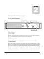
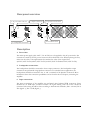
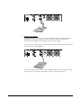
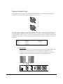
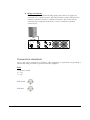
Power Amplifier D2 – D3 – D4 – D5 AUDAC PROFESSIONAL AUDIO EQUIPMENT Dual Channel Power Amplifier D2 – D3 – D4 – D5 User Manual & Installation Guide AUDAC PROFESSIONAL AUDIO EQUIPMENT User Manual & Installation Guide AUDAC http://www.audac.be [email protected] Index INTRODUCTION ..................................................................................................................................................................................................................... 3 ENVIRONMENT ...................................................................................................................................................................................................................... 4 SAFETY REQUIREMENTS ................................................................................................................................................................................................... 5 CAUTION – SERVICING ...................................................................................................................................................................................................... 5 OVERVIEW FRONT AND REAR PANEL .......................................................................................................................................................................... 6 FRONT PANEL OVERVIEW ............................................................................................................................................................................................... 6 FRONT PANEL DESCRIPTION ........................................................................................................................................................................................... 6 REAR PANEL OVERVIEW .................................................................................................................................................................................................. 7 REAR PANEL DESCRIPTION ............................................................................................................................................................................................. 7 CONNECTING THE AMPLIFIER ........................................................................................................................................................................................ 9 INPUT CONNECTIONS ........................................................................................................................................................................................................ 9 OUTPUT CONNECTIONS .................................................................................................................................................................................................. 11 CONNECTION STANDARDS ............................................................................................................................................................................................ 12 ADDITIONAL INFORMATION .......................................................................................................................................................................................... 13 TECHNICAL SPECIFICATIONS ....................................................................................................................................................................................... 13 PERSONAL NOTES............................................................................................................................................................................................................... 14 2 Introduction This section briefly describes the possibilities of the D-Series Dual Channel Power Amplifiers. T he D-Series Dual Channel Power Amplifiers are developed as an easy to use, flexible flexible solution for multifunctional use. During the development of the D2 – D3 – D4 – D5 power amplifier, the AUDAC-engineers wanted to achieve three goals: - Easy to use - Excellent sound quality - Modern and advanced design AUDAC’s D-series professional power amplifiers are suitable for the most common low impedance high power sound systems. The amplifiers are built as a 2 channel amplifier. The amplifiers are equipped with a multipurpose protection circuit which detects DC malfunction, short circuit, overheating and signal overload. The amplifiers are equipped with a balanced XLR input and Speakon output connector for every channel. 3 1 Chapter Environment Do not place this unit in an enclosed environment such as a bookshelf or closet. Ensure there is adequate ventilation to cool the unit. Do not block the ventilation openings. Do not place the unit in environments which contain high levels of dust, heat, moisture or vibration. Do not use the unit near water or other liquids. Make sure no water or other liquids can be spilled, dripped or splashed on the unit. Do not place objects on top of the unit. Place the unit on a stable base. 4 Safety Requirements Always handle the unit with care. Only use a grounded socket outlet and a power cord with grounding plug. This unit is not a toy. It should not be operated by children. Do not stick objects through the openings of the D2 – D3 – D4 – D5. Do not open the unit (risk for electrical shock). Always read the user manual before getting started. CAUTION – SERVICING This unit contains no user serviceable parts. Refer all servicing to qualified service personnel. Do not perform any servicing unless you are qualified to do so. Note This product conforms to the following European Standards: EN 50081-1: 1992, EN 50082-1: 1992, EN 60065: 1994 5 2 Chapter Overview front and rear panel Front panel overview 2. Gain controls: 3. Indicator LED’s 1. Power Switch Description 1. Power switch: By means of the power switch, the amplifier can be turned ON and OFF. When the amplifier is switched on, the blue LED located next to the power button will illuminate. 2. Gain control knobs: These rotary gain control knobs allow you to adjust the level for each individual channel. 3. Indicator LED’s: These LED’s indicate the operation of the amplifier. There are three LED’s provided. A signal indicator, a Clip indicator, and a Protect indicator. The green signal indicator LED will illuminate when a signal is available on the corresponding channel. The yellow clip LED will illuminate when the channels output is being overdriven, and the red protection indicator will illuminate when the protection circuit of the corresponding channel is activated. The protection circuit will intervene during the startup procedure of the amplifier, when a problem occurs. The output signal will be interrupted when this LED is lit. 6 Rear panel overview 4. AC power inlet with fuse 6. Input connections 7. Operation mode switch 8. Ground lift switch 5. Loudspeaker connections Description 4. Power inlet: The mains power supply (230~240V / 50~60 Hz) has to be applied to this AC power inlet. The connection is made by an IEC power connector and is fitted with a fuse. When replacing the fuse, make sure the value of the replacement fuse matches the value of the original fuse. (T6.3AL/250V for D2, T8AL/250V for D3, T10AL/250V for D4 & T12AL/250V for D5) 5. Loudspeaker connections: The loudspeakers should be connected to these output connectors. The loudspeaker output connections are performed using Speakon connectors. For standard stereo applications, the loudspeakers should be connected to the +1 and -1 terminals of the Speakon connectors. More information about the connection possibilities can be found in the next chapter, connecting the amplifier. 6. Input connections: The input connections of the amplifier are performed using balanced XLR connectors. Every channel has an XLR input connector whereto the signal coming from the source should be connected. The wiring should be done according to international standards. (Pin 1: Ground, Pin 2: Hot (Signal +), Pin 3: Cold (Signal -)) 7 7. Operation mode switch: By means of this switch, the operation mode of the amplifier can be selected between stereo mode or bridge mode. For most standard applications the amplifier will be used in stereo mode whereby this switch should be turned to the left position. When using in bridged mode, the power of both channels will be merged with each other and this switch should be turned to the right position. 8. Ground lift switch: By means of this switch, the ground of the amplifier can be detached to interrupt ground loops. This can be useful when unwanted hum and buzz is caused by current flow along the cable shield between different devices. 8 3 Chapter Connecting the Amplifier Input connections The input connections of the amplifier are performed using balanced XLR connectors. Every channel has an XLR input connector. The input signal from the signal source, pre-amplifier or mixer should be connected to the XLR input connections. By means of the operation mode switch, the operational mode for the amplifier can be selected between Stereo mode and Bridge mode. The diagrams below show the connection possibilities for both Stereo and Bridge mode. 1) Stereo Mode: This is the default mode of how the amplifier is set in the factory, and will be the most common used setting for most applications (Left position of the switch). Connect both outputs from the stereo signal source to the Channel 1 and Channel 2 XLR input connectors of the amplifier. 9 2) Bridge mono Mode: In bridged mono mode, the power of both output channels is merged to deliver double the power to one single load. The operation mode switch should be positioned in the Bridge position (Right position of the switch). The output of the signal source should only be connected with the Channel 1 XLR input connector of the amplifier. For more information about how the loudspeakers should be connected in bridge mode, refer to the “Output Connections” section of this user manual. 10 Output connections The loudspeaker connections are performed by using Speakon connectors. The loudspeakers should be connected to the corresponding Speakon connector. The used Speakon connectors are 4-pole versions. At the contacts of Speakon 1 (Channel 1), are the output signals available for both output channels. Contacts +1 and -1 contain the signal for output Channel 1, while contacts +2 and -2 contain the signal for output Channel 2. The contacts of Speakon 2 (Channel 2) only contain the signals of Channel 2, which are available on contacts +1 and -1. Pin +1 Pin -1 Pin +2 Pin -2 Speakon 1 (Channel 1) Channel 1 + Channel 1 Channel 2 + Channel 2 - Speakon 2 (Channel 2) Channel 2 + Channel 2 n/c n/c 1) Stereo Mode: Stereo mode will be the most common operation method for this amplifier. The loudspeakers of each channel can be connected with a separate two-core connection cable. (or one four-core connection cable, carrying both signals for Channel 1 and Channel 2 when connecting by connector Speakon 1) 11 2) Bridge mono Mode: When the amplifier is switched in bridge mode, there will be one single load connected to the amplifier outputs. This load should be connected between the + terminal of Channel 1 and the + terminal of Channel 2. This can be done by connecting the loudspeaker between the +1 and +2 terminals of Speakon connector one. Connection standards The in- and output connections of AUDAC audio equipment are performed corresponding to international wiring standards for professional audio equipment. XLR: 1 = ground / shield 2 = +sig 3 = -sig XLR female: XLR male: 12 4 Chapter Additional Information Technical specifications Input Impedance Input Sense Frequency Response THD+N (1 kHz) Signal to Noise ratio Slew Rate Cross Talk (1 kHz) Damping Factor D2 – D3 Damping Factor D4 – D5 20 kΩ balanced 0.775 V 20 Hz – 20 kHz Less than 0.05% @ 8 Ω >93 dB 40V/µsec >70 dB @ 8 Ω >200 >400 RMS RMS RMS RMS Power Power Power Power @ @ @ @ 8 4 8 4 Ω Ω Ω Ω D2 D2 Bridged D2 Bridged D2 2 x 200 W 2 x 300 W 1 x 600 W n/a RMS RMS RMS RMS Power Power Power Power @ @ @ @ 8 4 8 4 Ω Ω Ω Ω D3 D3 Bridged D3 Bridged D3 2 x 300 2 x 450 1 x 900 1 x 1200 W W W W RMS RMS RMS RMS Power Power Power Power @ @ @ @ 8 4 8 4 Ω Ω Ω Ω D4 D4 Bridged D4 Bridged D4 2 x 400 2 x 600 1 x 1200 1 x 1600 W W W W RMS RMS RMS RMS Power Power Power Power @ @ @ @ 8 4 8 4 Ω Ω Ω Ω D5 D5 Bridged D5 Bridged D5 2 x 500 2 x 750 1 x 1500 1 x 2000 W W W W Protection DC, Short Circuit, Overheating, Overload Power Supply Weight Weight Weight Weight 230V AC, 50-60Hz D2 D3 D4 D5 21.3 22.7 24.0 26.0 Dimensions (W x H x D) Unit height kg kg kg kg 483 mm x 88mm x 495 mm 2HE 13 Personal Notes 14